Resistance standards with nominal value 10kΩ are quite a common tool in voltage and resistance metrology labs. This value is often used to perform artifact calibration on instruments such as 8½-digit HP/Agilent/Keysight 3458A or multifunctional Fluke 5700A/5720A/5730A 7½-digit calibrators.
I always wanted to make a 10 kΩ reference resistor myself and thought the hermetically sealed, wirewound Ohmite HS520A would be a good start [1] .

It features the following performance parameters:
| Parameter | Value | Unit |
|---|---|---|
| Resistor value | 10000 | Ω |
| Tolerance | 0.1 | % |
| Power rating | 1.5 | W |
| Temperature coefficient | 3 | ppm/°C |
| Voltage rating | 900 | V |
| Min operational temperature | -10 | °C |
| Max operational temperature | +80 | °C |
Table 1. Ohmite HSP 10 kΩ specifications
Datasheet for Ohmite HSP series
Disclaimer
Redistribution and use of this article, any part of it or any images or files referenced in it, in source and binary forms, with or without modification, are permitted provided that the following conditions are met:
- Redistributions of article must retain the above copyright notice, this list of conditions, link to this page (https://xdevs.com/article/bsw104/) and the following disclaimer.
- Redistributions of files in binary form must reproduce the above copyright notice, this list of conditions, link to this page (https://xdevs.com/article/bsw104/), and the following disclaimer in the documentation and/or other materials provided with the distribution, for example Readme file.
All information posted here is hosted just for education purposes and provided AS IS. In no event shall the author, xDevs.com site, or any other 3rd party be liable for any special, direct, indirect, or consequential damages or any damages whatsoever resulting from loss of use, data or profits, whether in an action of contract, negligence or other tortuous action, arising out of or in connection with the use or performance of information published here.
If you willing to contribute or add your experience regarding instrument repairs or provide extra information, you can do so following these simple instructions.
Resistance standard design and build process
The resistor case is made of a brass tube with glass sealed feedthroughs soldered to it at both ends. When the resistor arrived a first temperature measurement disappointed (see Figure 1). The measurement was performed with a Prema 5017SC and an incubator with Arroyo 5305 TEC controller. The result shows a linear part of α = 1.97 ppm/°C and quadratic component of β = 0.065 ppm/°C2, so the resistor got tossed for a while into the drawer, until I came across an article by lymex on bbs.38hot.net [2]. A translated English-version of this article can be found attached below.

Figure 1. Initial TCR measurement without any compensation
Translated article of 38hot.net Lymex post about TCR compensation for standard resistors
In his article, a resistor compensation scheme describes using an NTC with series resistor Rp in parallel to Rm – this is our HS520A resistor to compensate the quadratic component of the TCR, which adds an additional negative linear component to it. The overall negative linear component is then compensated with a copper wire resistor Rc and finally the arrangement is trimmed to its final value with Rs (see Figure 2).
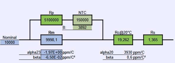
Figure 2. Design stage of the compensation network for α and β components
The Excel spreadsheet to play with provided by lymex and translated to English can be downloaded in [3]
The 5.1 MΩ resistor together with a Littlefuse Inc. glass encapsulated thermistor type 154JG1K for compensating the β part was covered with a heat shrink tube and attached to the HS520A resistor. Another thermistor of type GA10kA3 with PTFE insulated leads was attached to the HS520A resistor acting as a temperature sensor. Everything was fixed with some Kapton tape around the HS520A (see Figure 3).
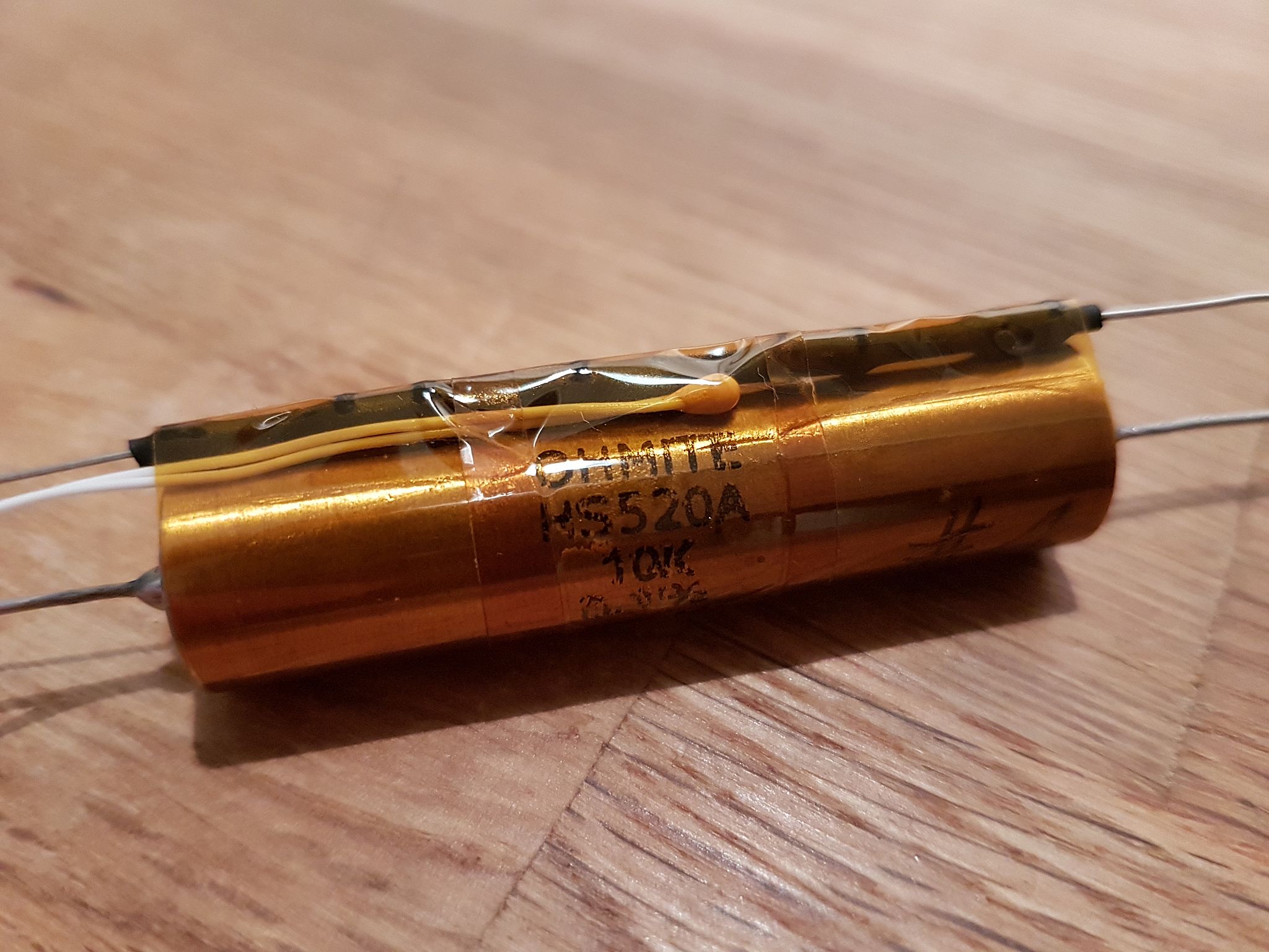
Figure 3: HS520A with series resistor and NTC in a heat shrink tube parallel and a thermistor as temperature sensor attached to it
An enameled copper wire of Ø0.16 mm was used for Rc and wound bifilar around the HS520A resistor case, again fixed with Kapton tape (see Figure 4). It compensates the negative linear component.
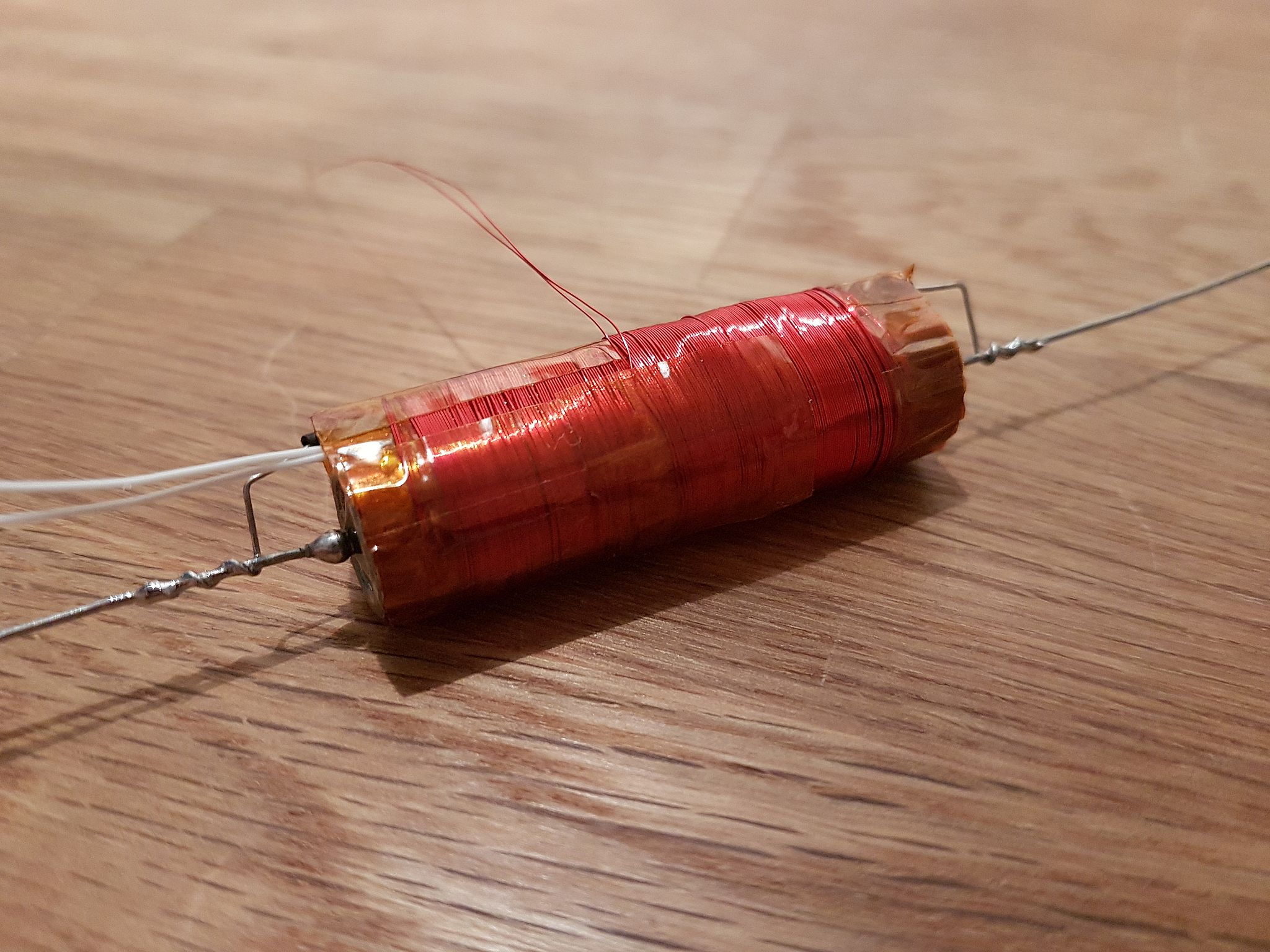
Figure 4: Resistor with copper wire resistor wound to it
A Rose 04.08 12 08 powder coated aluminum die cast case [4] was prepared with the holes for some Pomona 3770 binding posts. The resistor is attached by some Teflon standoffs to an aluminum mounting plate. Rs was created by using 2 × 2.7 Ω 1 % resistors with ±50 ppm/K (see Figure 5).

Figure 5: Resistor in the Rose 04.08 12 08 powder coated case with mounting plate and Teflon standoffs
After everything was set up a new temperature profile was performed, this time using a Solatron 7081 in 7×9 mode with the already mentioned thermal chamber. This resulted in the behavior presented in Figure 6. For the measurements the drift correction was turned off and manually initialized before every temperature run.

Figure 6: Initial temperature measurement after setting everything up
From here the copper wire was then shortened by 10 cm and the temperature profile repeated.
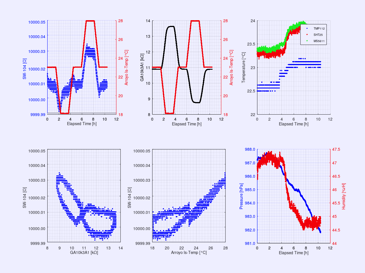
Figure 7: Temperature measurement with 10 cm of copper wire removed.
The copper wire was shortened by another 20 cm and the temperature profile repeated.

Figure 8: Temperature measurement with 30 cm of copper wire removed.
Eventually, another 60 cm of copper wire were removed and the temperature profile repeated.
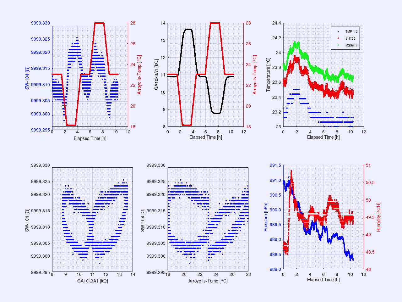
Figure 9: Temperature measurement with 90 cm of copper wire removed
The result shows an almost equally distributed temperature behavior. Finally, Rs was adjusted by replacing the 2 × 2.7 Ω with 3.3 Ω || 5.6 Ω, as shown in the final trimming scheme in Figure 10.

Figure 10: Final trimming scheme
In this final arrangement the last temperature (see Figure 11) and an 8-hour stability measurement at lab temperature right afterwards were performed (see Figure 12). For the stability measurement the drift correction of the Solatron 7081 was initialized every hour. It is visible, that it takes multiple hours, here about 5.5 … 6 h, for the resistor to fully stabilize after a temperature step.

Figure 11: Final TCR measurement result

Figure 12: 8 h stability test with drift compensation of Solatron 7081 turned off
Conclusion
A low TCR resistor reference can be built from readily available components on hobby budget. Although everything can be calculated upfront it still needs a lot of tweaking to get the final result right in a practical build.
There is probably a small time lag between the temperature of the copper wire resistor Rc and the HS520A resistor. Filling the case with some non-conductive ceramic balls or the like might improve the thermal transfer. A transfer fluid such as Galden could help as well, but requires a sealed case and fluid-tight binding posts.
As one might have noticed the temperature slopes of 0.1 °C/min used here were still too high, but the smallest my Arroyo 5305 TEC controller can do on its own. A way to get out of this limitation is to use software-controller such as xDevs.com TECkit which is also freely available on GitHub .
The resistor now needs comparison to other calibrated sources and last but not least its label, “SW-104”.
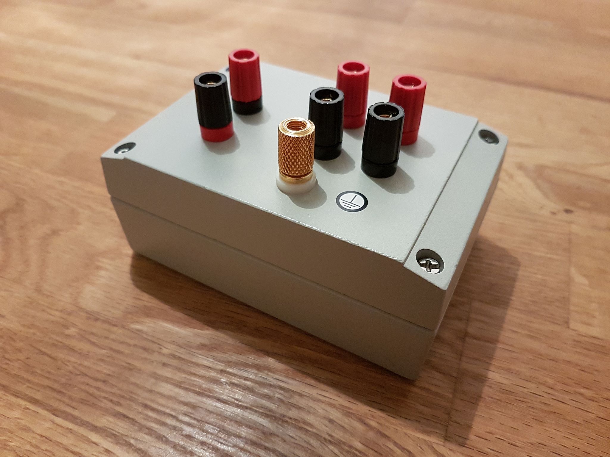
Figure 13: The finished ready-to-use 10000 Ω SW-104 reference resistor
In retrospective I come to the conclusion that the beta is overcompensated, so the series resistor of the NTC needs to be slightly reduced. The heat shrink over these series resistors and the NTC adds an extra time lag that should be avoided. So the heat shrink better has covered the solder joints only, not the complete components.
So if I find the time I will rework the build and hopefully get better results out of it. Just for the fun of it and to see what can be reached at the extremes.
Modified: March 6, 2022, 4:26 p.m.