Sometimes it’s important to know noise floor of digital multimeter, before actual purchase, for example if task require measurement of small amplitude signals and for low-noise applications. Usually maximum noise is defined by specification, but it’s not always easy to correlate this information with specific range or speed setting. If we can test actual device, it would be interesting to see if actual instrument behave differently that spec, considering age of most used meters in scope. Some users have them already well aged, often over 20 years.
That’s why this project starts open evaluation with main purpose to capture various multimeter data and analyze results in human-readable form.
Before we start, let’s make few important notes:
- Measurements here, unless specifically stated are performed with short on input. This is not truly a measure of instrument’s ADC alone noise or signal noise. This is overall measurement path noise, with all attenuation, filtering, relay components involved.
- Noise analysis of ADC itself would be much more difficult to do, and without much practical outcome. Also that would prohibit most of members participation, as it would need opening expensive instruments, dealing with risk of damage. So I opted against this approach on purpose.
- Noise test data performed by other members are not 100% comparable, as they were performed in different environment, often with different setups. It’s more like indication only at this moment, unless we find better way to show correlation, instead of gathering multiple datasets from same model of multimeter, and filtering out “questionable” results.
Want to participate? Well, it’s easy!
If you want get your meter tested and added into chart/data summary, here’s simple steps for you:
In case EZGPIB-script posted below suits your instrument, collecting data is easy:
1. Have to use interface to log data from meter, such as RS232 or GPIB/LAN. If there is USB port to transfer data from meter , that will work too.
2. Just unpack EZGPIB, open matching script and run it on your instrument address (GPIB or VISA)
3. Gathered data will be automatically saved in C:\MyMeasurements
4. Now you can make note or readme.txt file with meter information, mains parameters (60Hz or 50Hz, etc)
5. Add special notes if needed, if meter modified/non-standard (e.g. after repair with different parts, or changed parts, etc)
6. Send your files to ftp://xdevs.com/ with login and password datashort
If your meter not yet added with EZGPIB, it would take little more work to do:
1. Have to use interface to log data from meter, such as RS232 or GPIB/LAN. If there is USB port to transfer data from meter , that will work too.
2. Disable all filtering / math functions on meter. We want get clean data from ADC subsystem. Processing can be done later on PC, in case if needed.
3. Set range, for example 100mV or 2V. Enable synchronous autozero if there is such in meter.
4. Set NLPC aligned to power cycles (for example 1.00 NPLC, not 1.01 or 0.95)
5. Enable high-impedance mode, if meter allows selection between 10Meg/Hi-Z (for example 34970A, 344xxA).
6. Capture data. Suggest to capture at least 5 minutes.
7. Now change range/NPLC and get more data samples.
8. After all data collected, make note or readme.txt file with meter information, mains parameters (60Hz or 50Hz, etc)
9. Add special notes if needed, if meter modified/non-standard (e.g. after repair with different parts, or changed parts, etc)
10. Send your files to ftp://xdevs.com/ with login and password datashort
Autozero mode should be enabled, as it would reduce greatly offsets due to ambient temperature variations. We don’t want long-term offsets to be confusing as bigger noise span.
If you run settings manually, you can use table below to select points of intereset. Number meaning order to run (for example run only tests 2,3,4, if you not interested in fast NPLCs settings and ranges over 20V)
| 0.01 NPLC | 0.1 NPLC | 1 NPLC | 10 NPLC | 50 NPLC | 100 NPLC | 1000 NPLC | |
|---|---|---|---|---|---|---|---|
| 100mV | +11 | +10 | +7 | +3 | +4 | +5 | +9 |
| 1V | +11 | +10 | +7 | +2 | +4 | +5 | +9 |
| 10V | +11 | +10 | +1 | Primary | +4 | +5 | +5 |
| 100V | +11 | +10 | +8 | +6 | +8 | +9 | +9 |
| 1000V | +11 | +10 | +8 | +6 | +8 | +9 | +9 |
EZGPIB tool for measurements automation.
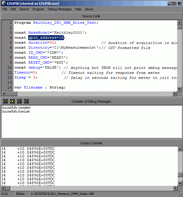
To make dataset capture simple and easy I’d suggest to use EZGPIB tool from Ulrich Bangert DF6JB
EZGPIB is a simple pascal-based tool which can access instrument via GPIB, TCP or VISA library interface. It also supports Prologix GPIB-USB interface dongle. Tool supports Windows XP and 7, but should also work on other Windows operation systems. In my case I had zero issues with Windows Server 2008 ×64. Best idea to unpack EZGPIB to root folder C:/EZGPIB, as it’s old tool and may not like complex filenames.
It was tested well with Silicon Labs CP2103 USB-RS232 bridge and National Instruments GPIB-USB-HS dongle.
Toolkit to parse/process data, extract RMS noise
To automated CSV-parsing and standard deviation (SD) value calculation, I wrote very simple dirty tool in python
Usage is simple: Copy it into same folder as captured data from EZGPIB (for example c:\MyMeasurements\Keithley2000\) and run it.
It will generate math results with all settings taken from filename, showing crucial math data summary.:
c:\MyMeasurements\Keithley2001>parse_noise_sd.py
|_.  Multimeter    |_.  Range       |_.  NPLC  |_.   Counts  |_.     Sq.sum     |_.   Average   |_.     SD      |_.     SD,uV   |
| Keithley2001          | .2            | .01   |       15195   | -0.28784208   | -1.894321E-05 | 4.603746E-06  |   4.604       |
| Keithley2001          | .2            | .1    |       14652   | -0.19161943   | -1.307804E-05 | 5.133031E-07  |   0.513       |
| Keithley2001          | .2            | 1     |       9514    | -0.05802637   | -6.099051E-06 | 2.026150E-07  |   0.203       |
| Keithley2001          | .2            | 10    |       1028    | -0.00569434   | -5.539236E-06 | 4.001432E-07  |   0.400       |
| Keithley2001          | 1000          | .01   |       13876   | -144.28255000 | -1.039799E-02 | 1.615199E-03  |1615.199       |
| Keithley2001          | 1000          | .1    |       13819   | 6.25410000    | 4.525725E-04  | 6.129784E-04  | 612.978       |
| Keithley2001          | 1000          | 1     |       9681    | 54.74475000   | 5.654865E-03  | 1.216511E-03  |1216.511       |
There will be also output.txt file generated with table, so you can copy data and use later.
Formatting of table is performed by markup textile syntax.
Test results
Such amount of data even for single meter becoming little difficult to clearly show, so we tried different ways.
Most simple is to show history graph of measured values over time, just like we see on oscilloscope or datalog graph.
First attempt:
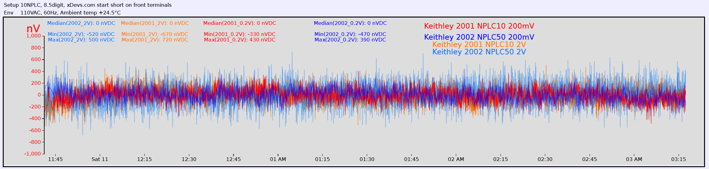
While this graph shows all data samples, after adding even just three noise plots for various NPLC, it become a big colorful mess, which is impossible to distinguish.
Another try on second attempt was to convert samples into histogram plot:
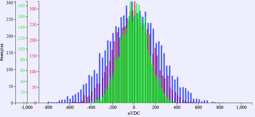
Better, but scaling graphs and dealing with amplitude noise becoming trouble some.
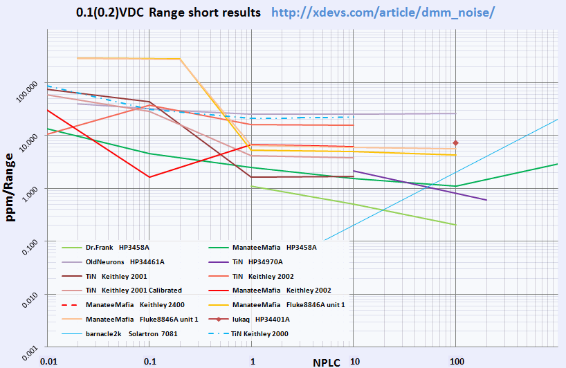
With bit of community help, third attempt is to calculate RMS-value of signal and use log graph.
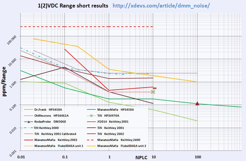
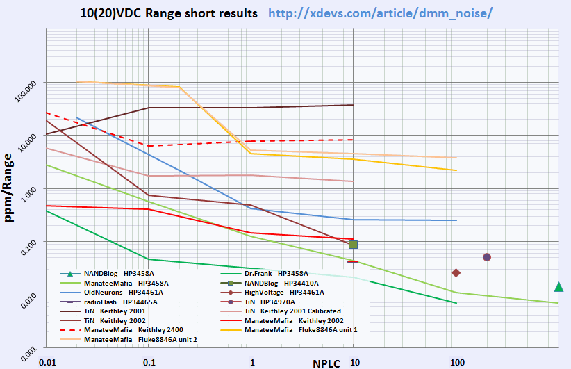
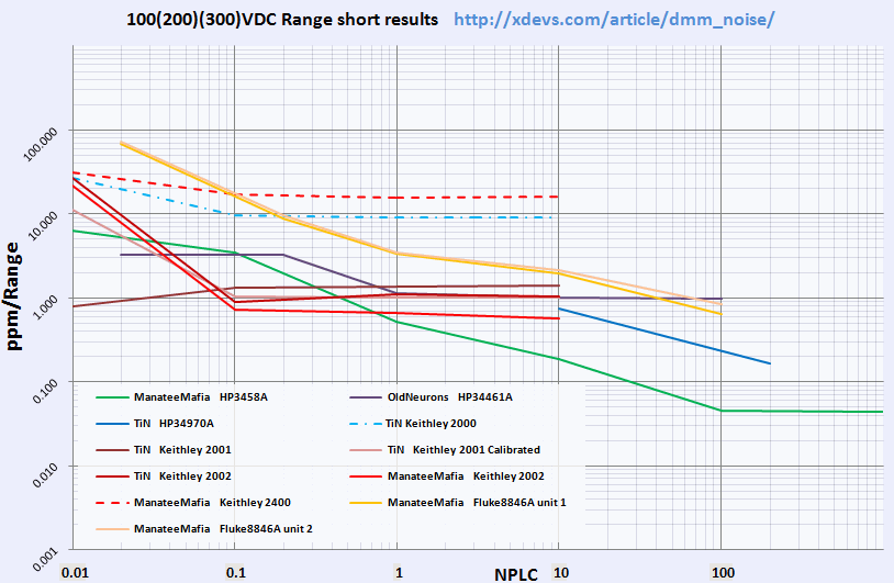
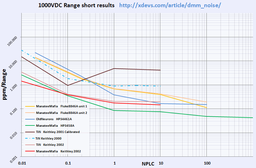
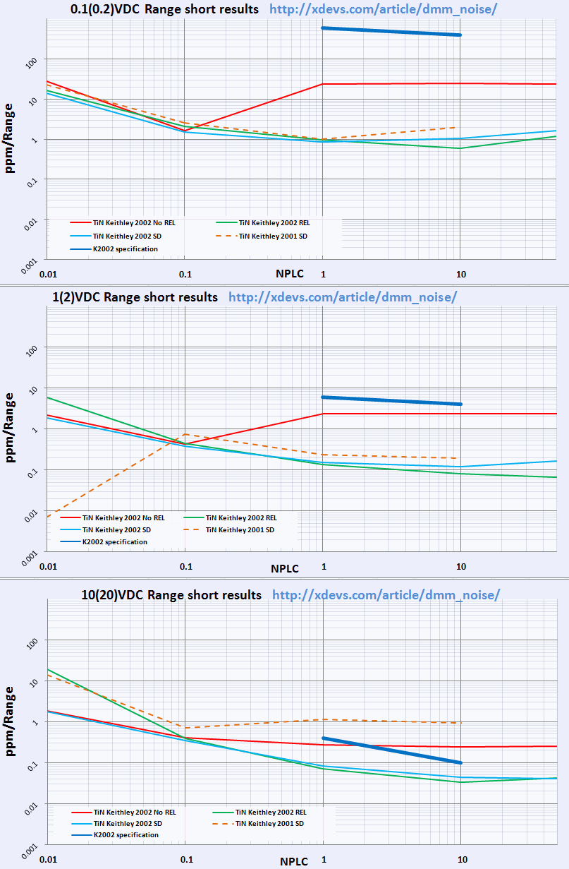
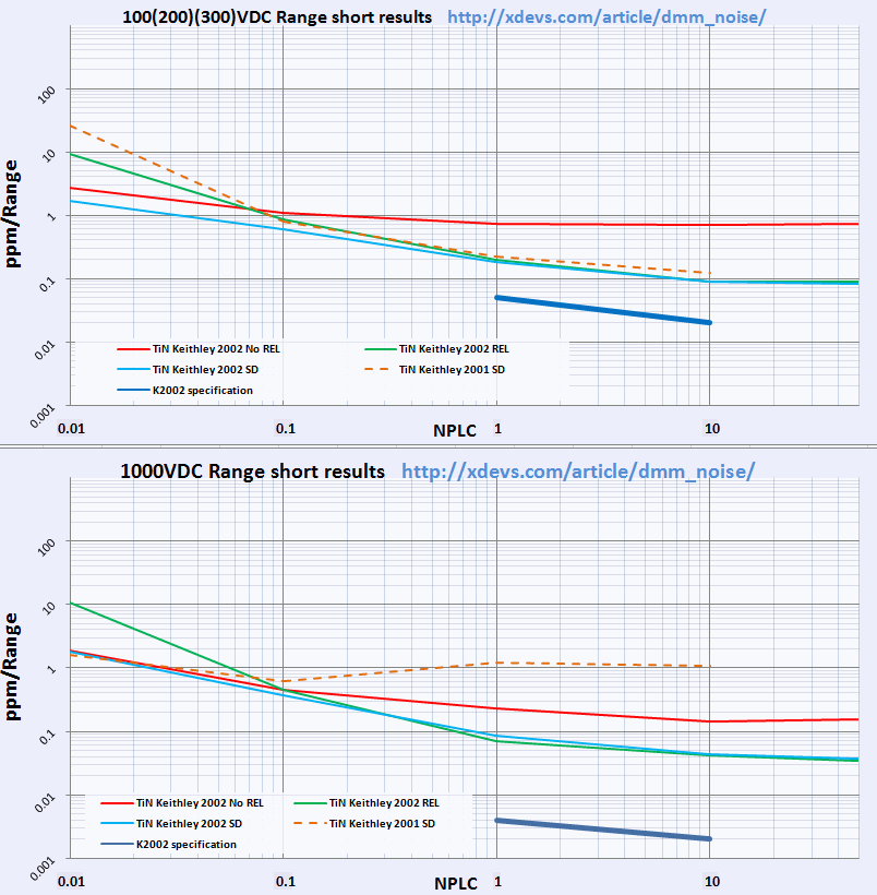
Results further converted into ppm/Range deviation, which is easy to read and represent.
All graphs below have uniform log axis, both vertical and horizontal.
Vertical axis : Noise figure, in ppm/range, from 0.001 to 1000
Horizontal axis : Measurement speed, in NPLC setting, from 0.001 to 1000
Summary results in range DCV 100mV (200mV)
Summary results in range DCV 1V (2V)
Summary results in range DCV 10V (20V)
Summary results in range DCV 100V (200V or 300V in case of HPAK 34970A)
Summary results in range DCV 1000V
All this data is pretty coarse and raw, so take results with great care at this moment.
Forth approach:
Since RMS-value can easily cause a problem if measurement offset is present (which is often the case if calibration was done long time ago, or with different calibration temperature than measurements were taken), it would increase RMS value we use for graphs as well. It would be read as false higher reading noise, than actually present.
To mitigate this issue, only Standard Deviation should be calculated instead.
To test this approach, two meters were tested so far:
Appendix А
Measured noise levels with applied signals on inputs
To be done…
Appendix B
Additional measurements
Solartron 7081 DMM results are shown separately, as integration time in this machine set in seconds, not usual NPLC.
Results table, Barnacle2K Solartron 7081
Appendix C
If you want manually set some settings, here are examples with SCPI-command queue’s:
For Keithley 2001/2002 multimeters:
:SYST:AZER:TYPE SYNC;           // Here we enable autozero sync
:SYST:LSYN:STAT ON;             // Here enable line sync
:SENS:FUNC 'VOLT:DC';           // Measure voltage DCV
:SENS:VOLT:DC:NPLC 10;          // Set NPLC to 10
:SENS:VOLT:DC:RANGE 2;          // Set range manual to 2V
:SENS:VOLT:DC:DIG 8.5;          // Set resolution to 8.5 digits
:SENS:VOLT:DC:AVER:STAT OFF;    // Filter off
:TRIG:SEQ:SOUR TIM;             // Set trigger source from timer
:TRIG:SEQ:DEL 1;                // Set timer to 1 second
:READ?                          // Read data
For Keithley 2182 nanovoltmeter:
:SYST:AZER:STAT ON;             // Here enable autozero
:SYST:FAZ:STAT ON;              // Here we enable front end autozero
:SYST:LSYN:STAT ON;             // Here enable line sync
:SENS:FUNC 'VOLT:DC';           // Measure voltage DCV
:SENS:VOLT:CHAN1:LPAS:STAT OFF; // Analog filter off
:SENS:VOLT:CHAN1:DFIL:STAT OFF; // Digital filter off
:SENS:VOLT:CHAN1:NPLC 5;        // Set NPLC to 5
:SENS:VOLT:CHAN1:RANG 10;       // Set range manual to 10V
:SENS:VOLT:CHAN1:DIG 8.5;       // Set resolution to 8.5 digits
:TRIG:SEQ:SOUR TIM;             // Set trigger source from timer
:TRIG:SEQ:DEL 1;                // Set timer to 1 second
:READ?                          // Read data
Appendix D
For sanity check here’s simple table of NPLC settings and period conversion
| 60Hz | Speed,SPS | 50 Hz | Speed, SPS | |
|---|---|---|---|---|
| 1000 PLC | 16.67s | 0.06 | 20s | 0.05 |
| 200 PLC | 3.33s | 0.3 | 4s | 0.25 |
| 100 PLC | 1.67s | 0.6 | 2s | 0.5 |
| 50 PLC | 833 ms | 1.2 | 1s | 1 |
| 20 PLC | 333 ms | 3 | 400ms | 2.5 |
| 10 PLC | 167 ms | 6 | 200ms | 5 |
| 5 PLC | 83.3 ms | 12 | 100ms | 10 |
| 2 PLC | 33.3 ms | 30 | 40ms | 25 |
| 1 PLC | 16.7 ms | 60 | 20ms | 50 |
| .1 PLC | 1.67 ms | 600 | 2ms | 500 |
| .01 PLC | 160 us | 6000 | 200us | 5000 |
Appendix E – Source CSV-data with test results of each instrument above
Excel-file with all data and graph sources – as of 7 August 2015.
Excel-file with SD data and test graphs – as of 8 August 2015
All files stored here
Results table, Dr.Frank HP3458A
Results table, HighVoltage Agilent 34461A
Results table, Jf2014 Keithley 2001
Results table, KedasProbe Rigol DM3068
Results table, lukaq HP 34401A
Results table, Todd’s Fluke 8846
Results table, Todd’s HP 3458A
Results table, Todd’s Keithley 2002
Results table, Todd’s SMU Keithley 2400
Results table, HP 34410A & HP 3458A
Results table, Agilent 34461A
Results table, Agilent 34465A
Results table, xDevs.com Agilent 34970A+34901A
Results table, xDevs.com Keithley 2001 #13
Results table, xDevs.com Keithley 2001 #13
Results table, xDevs.com Keithley 2001 calibrated 2014
Results table, xDevs.com Keithley 2002
Appendix F – Scripts for EZGPIB to automate data gathering
EZGPIB Tool download – 2.1 MB. Since Ulrich Bangert DF6JB is no longer with us, and his site not working, I rehosted it here, so his work not lost.
GPIB scripts:
EZGPIB script for Fluke 8846A, ver.1.01
EZGPIB script for HP 34420A ver.1.01
EZGPIB script for HP 3458A ver.1.01
EZGPIB script for Keithley 2400 ver.1.01
EZGPIB script for Keithley 2001 ver.1.01
EZGPIB script for Keithley 2002 ver.1.02
VISA (RS232) scripts:
Beta-version EZGPIB-script for Keithley 2000 ver.0.20 via RS232 VISA
This script not very well tested and may cause Errors, so it need some work still.
Appendix G
Credits:
- Cookies to Todd Micallef for great job with EZGPIB scripts and hints! Thank you!
- Ulrich Bangert for EZGPIB tool (Old webhost)
- OldNeurons for Excel hints
- Dr.Frank for valuable notes and suggestions
- Plesa for contributions with script and RPI2
Revision log
- 7 August 2015 : Added Keithley 2000 initial data (xdevs.com)
- 8 August 2015 : Change scripts and output data to reflect standard-deviation SD/range value, instead of RMS
- 23 August 2015 : Added v1.02 script for Kei2002 with floating point error fix from plesa
Please jump in comments if you have any questions or suggestions.
Modified: April 17, 2016, 5:08 a.m.