In this article primary power supply design will be covered. This is for our very own DC voltage standard/source unit, which is in slow work in progress for a while. As quick recap, main target of device is to couple precision stable voltage reference with composite 32-bit DAC and ±1000V output power stage to provide programmable 7½-digit output. It’s a difficult task, and production units on market cost many thousands dollars. Main purpose of the build is self-education and use in homebrew precision lab. This time we talk about power supply for whole thing.
Recently I received well-packed heavy box with some goodies, which I had pending long time ago.


What is it? Everything in mains-powered instrumentation starts with primary power supply. Vast majority of precision instrumentation is sensitive to noise and excessive ripple in power rails, so it’s often to find bulky linear 50/60Hz transformers instead of compact switching PSUs. Even special low noise switching supply generate wideband noise, which is hard and expensive to filter out. Common solution to this is to use linear transformers with separate sections for digital and analog low noise power rails, followed by low noise LDO post-regulators to produce clean and quiet power. Sometimes even these measures are not good enough, dictating need of using onboard battery cells to get clean voltage. But talking about linear transformer, which one to get?
If you looking into lowest noise and EMI pickup from noisy mains, usual transformer from store at the corner may not be enough. Vendors like Keithley, Fluke know this very well since very beginning, and solve this with improved transformer designs, often with extra faraday cages and mu-metal shields around windings to reduce capacitive coupling between primary and secondary sections.
There transformers are expensive, not often visitor on shop shelves, and most of instruments have them custom made and designed to fit specific need. Let’s take a look on two used in Fluke 332D/335D series DC voltage standards. First thing – schematics from Fluke 332D Operation and Service manual:
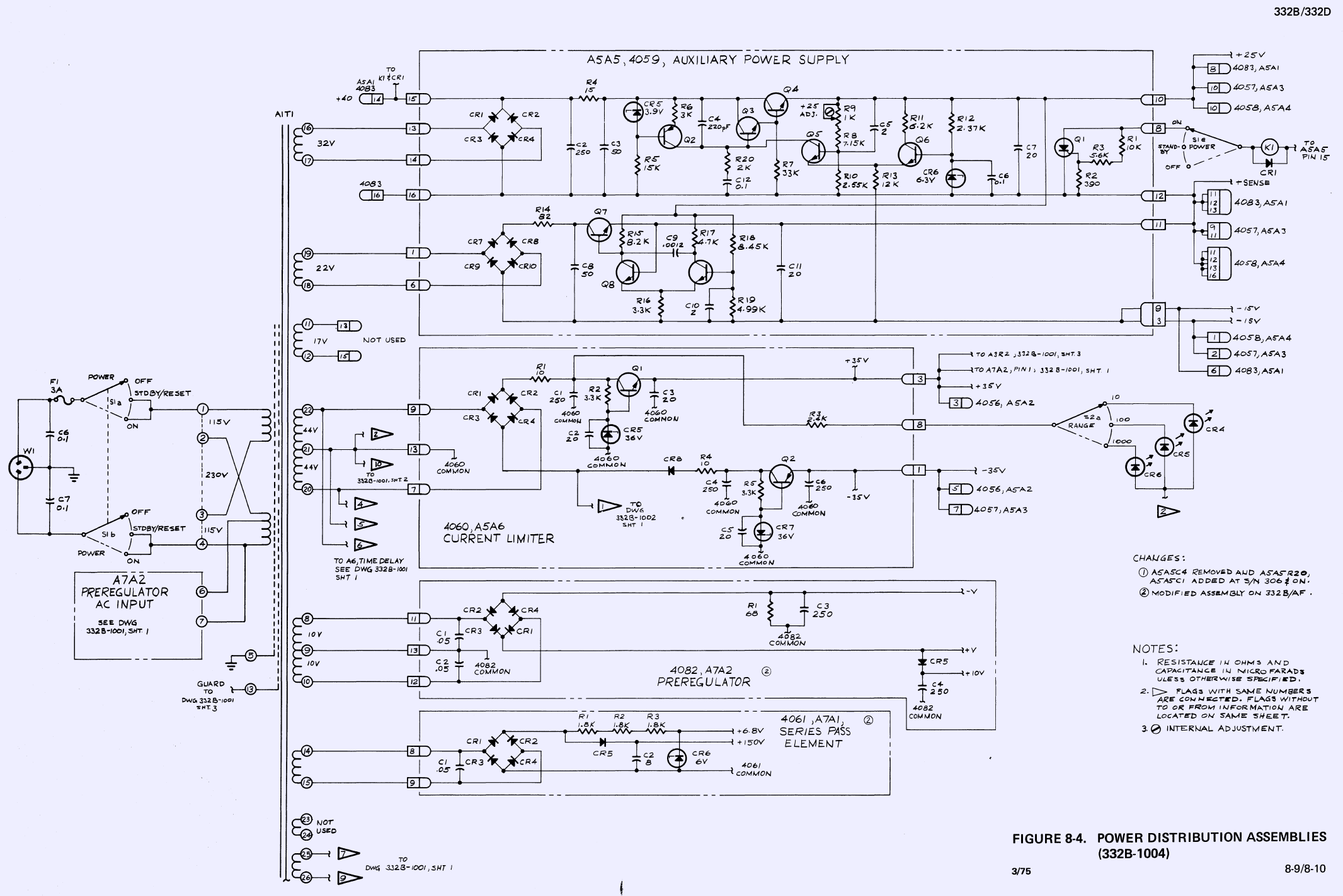
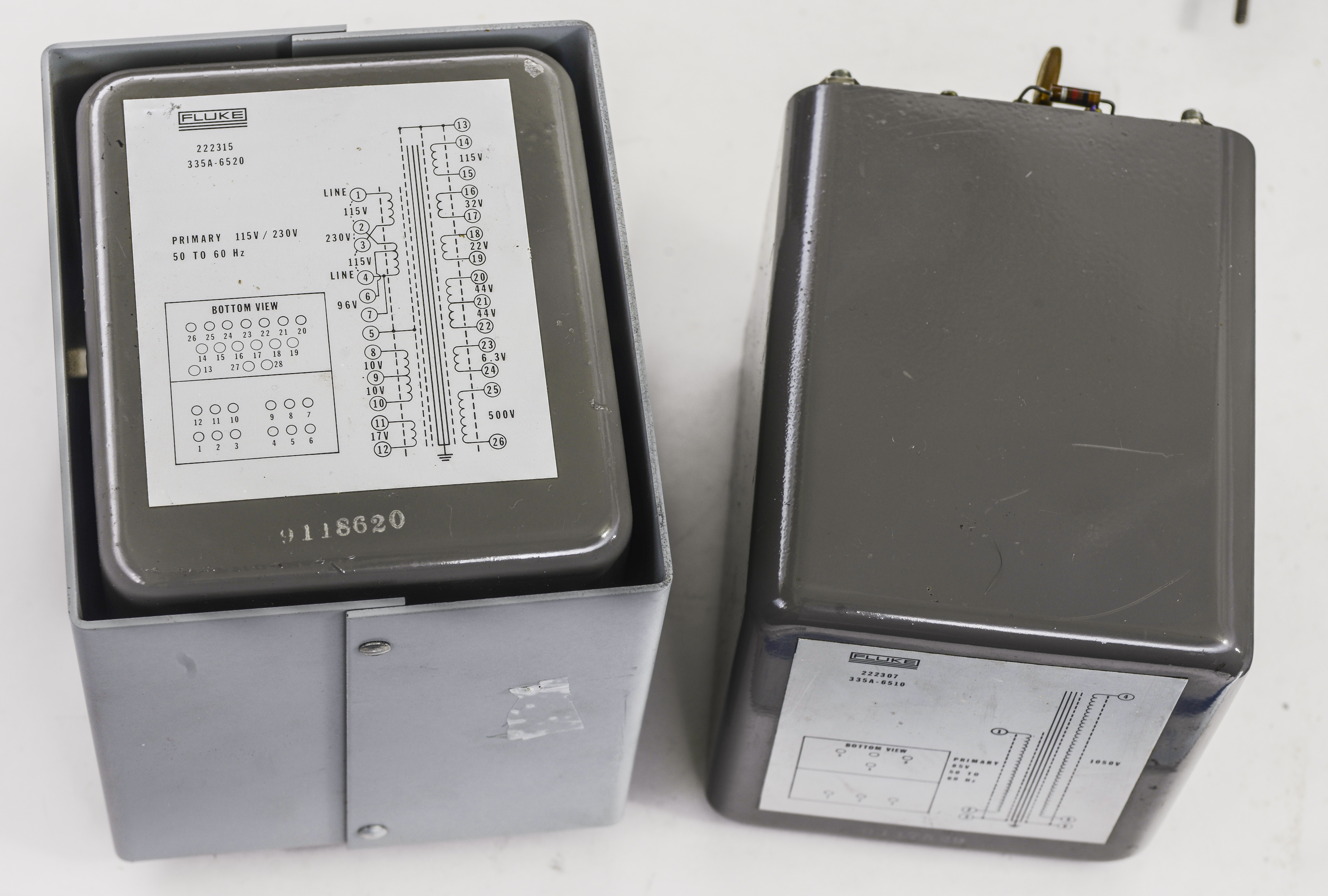
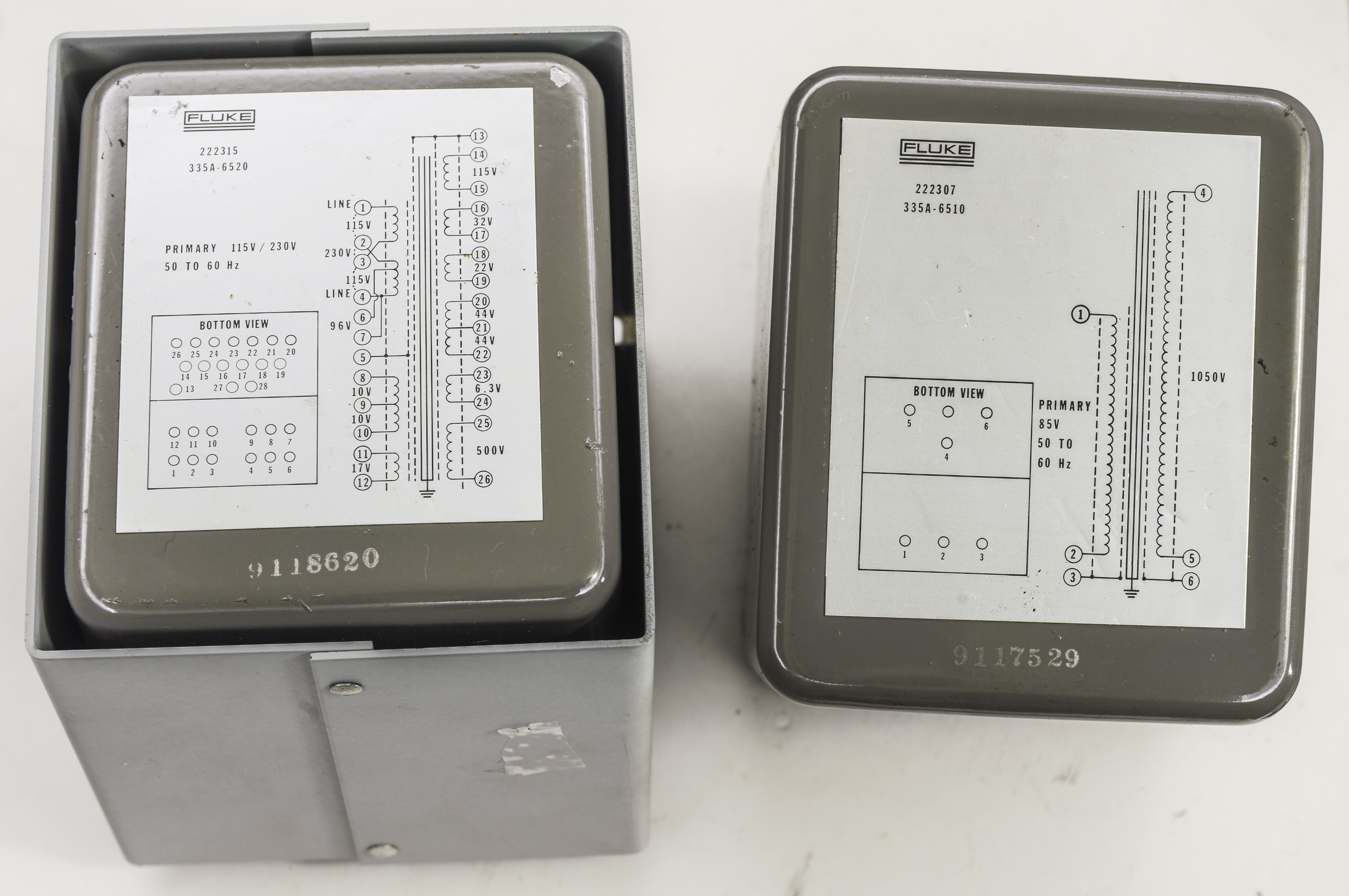
Transformer can be wired for either 115VAC or 230VAC mains voltage, with 96VAC tap going to second transformer. There are many secondary windings and sections to provide plenty of voltages.
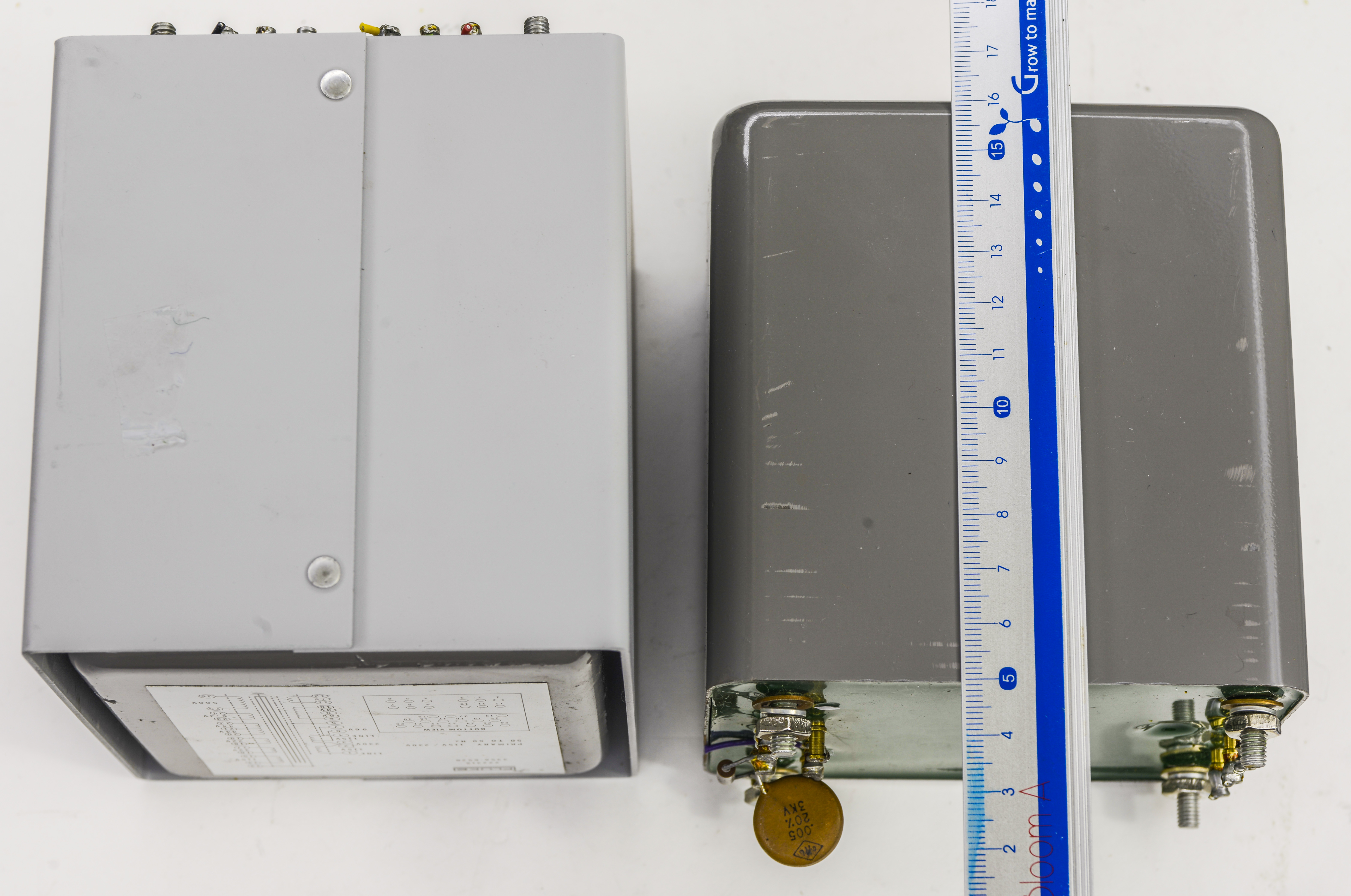
Second high-voltage transformer have just windings, primary to take 96 VAC input and secondary to provide high voltage output. Both transformers are enclosed in mu-metal can and epoxied with green hard plastic. Their weight about 5.1kg, each.
Here are transformers themselves:
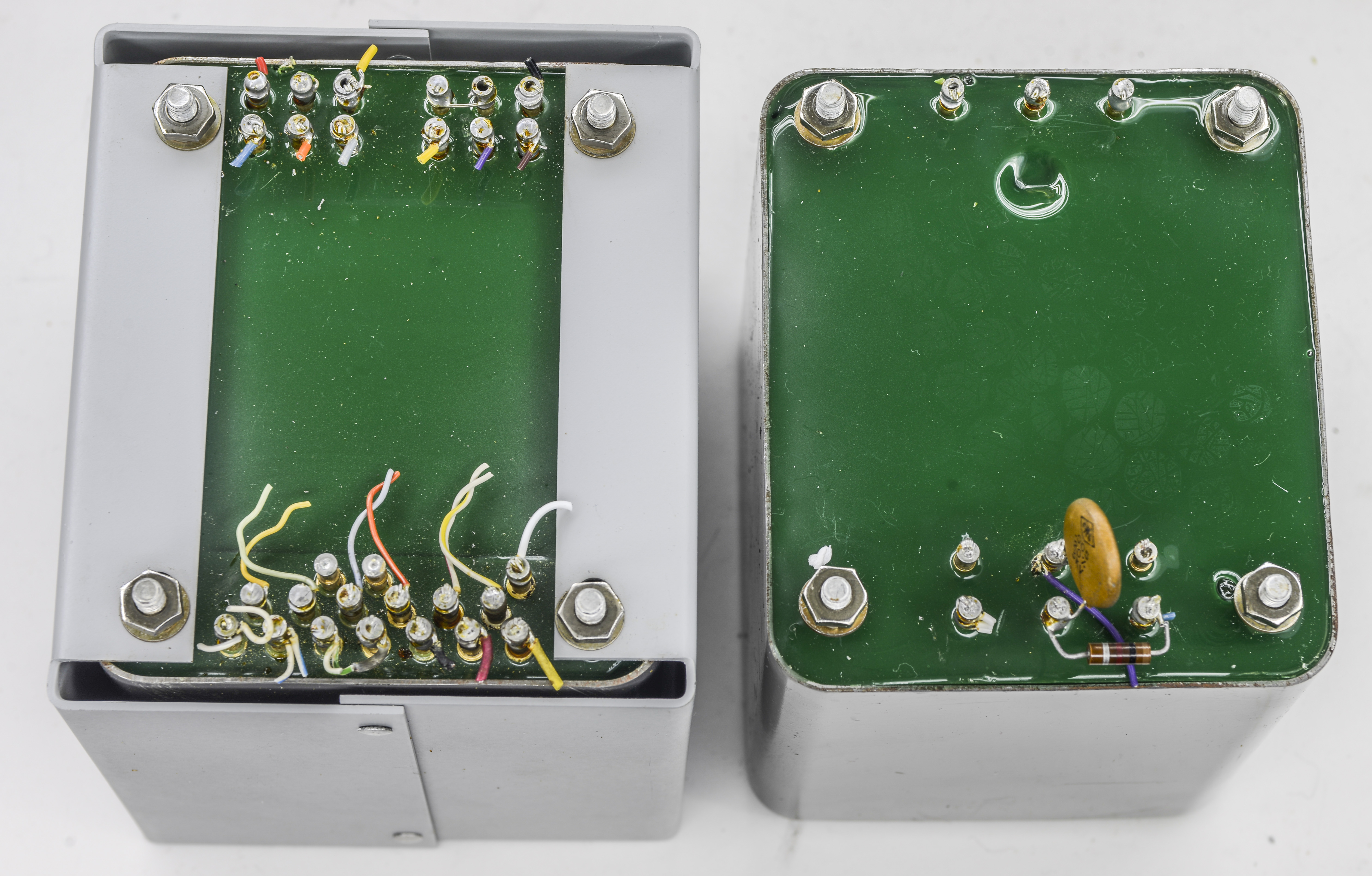
Peek on the bottom where all the connection ports are.
Measured resistances on transformer using Keithley 2001 in 4W-mode. Perhaps that can be handy for someone who have faulty Fluke 332D/335D.
| Winding | Rated voltage | Measured voltage | Measured resistance |
|---|---|---|---|
| 1-3 | Primary | N/A | 2.831 Ω |
| 2-4 | Primary | N/A | 2.7858 Ω |
| 2-6 | Primary | N/A | 0.4256 Ω |
| 4-6 | 96VAC tap | 92.1 | 2.3352 Ω |
| 4-7 | Short | N/A | 0.0024 Ω |
| 1-5 | Mains-shield | N/A | >1 GΩ |
| 8-9 | 10VAC secondary | 10.18 | 0.2908 Ω |
| 9-10 | 10VAC secondary | 10.18 | 0.3010 Ω |
| 11-12 | 17VAC secondary | 16.97 | 2.4356 Ω |
| 5-13 | Shield-Guard | N/A | >1 GΩ |
| 13-14 | Guard-Secondary | N/A | >1 GΩ |
| 14-15 | 115V secondary | 114.5 | 69.415 Ω |
| 16-17 | 32V secondary | 32.48 | 1.5668 Ω |
| 18-19 | 22V secondary | 21.82 | 3.4912 Ω |
| 20-21 | 44V secondary | 44.14 | 7.1379 Ω |
| 21-22 | 44V secondary | 44.12 | 7.2278 Ω |
| 23-24 | 6.3V secondary | 6.31 | 0.5358 Ω |
| 25-26 | 500V secondary | 494.8 | 101.347 Ω |
Table 1. Resistance measurements on Fluke 332/335D T1 transformer
High lethal voltages are generated by such transformers. Be extremely careful when using parts and circuits like this, otherwise severe electric shock or even death is possible! These are not toys!
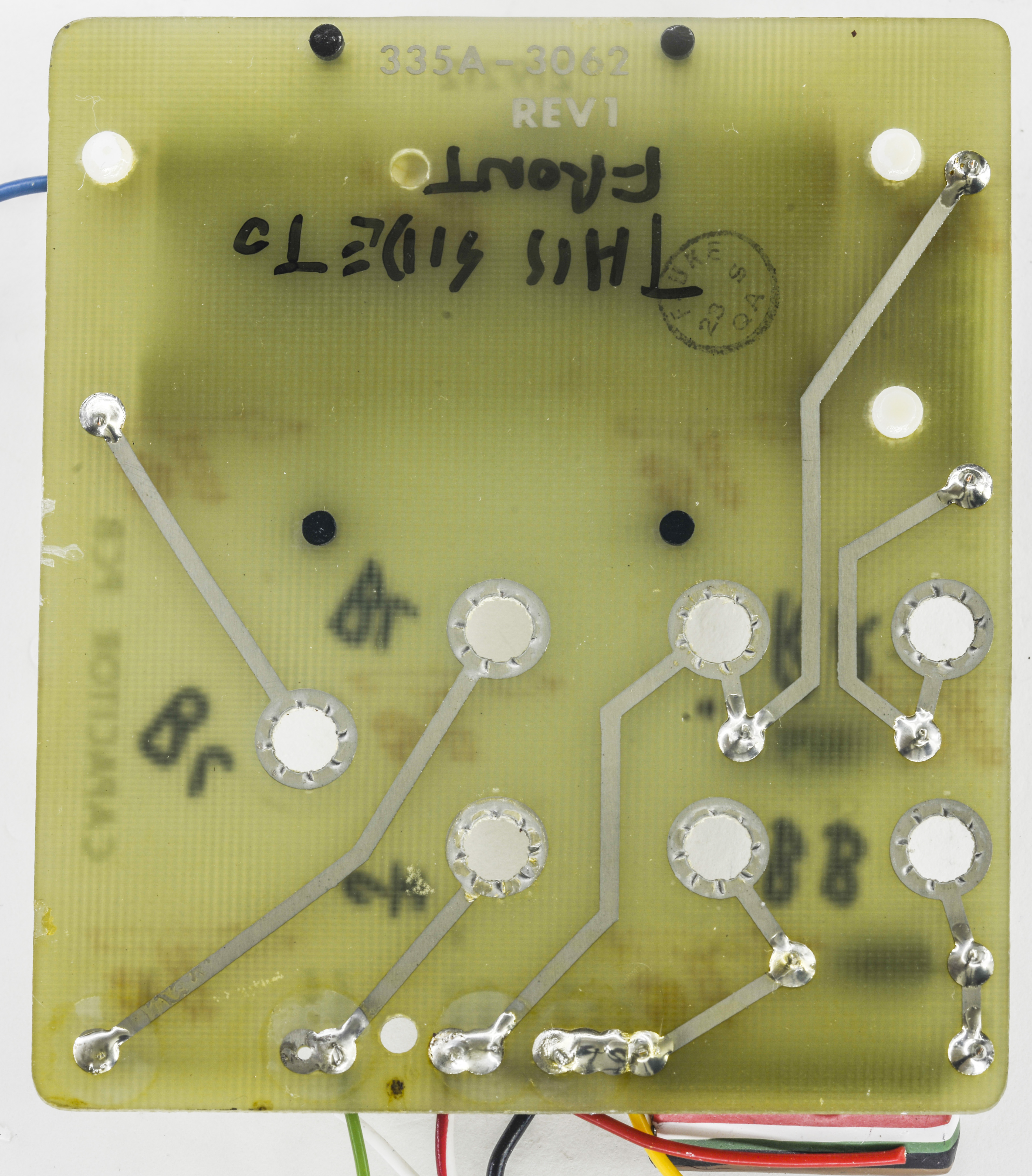
I also got some other parts from Fluke 332D/335D, like binding posts and reference cal board with Fluke wirewound low-tempco resistors.

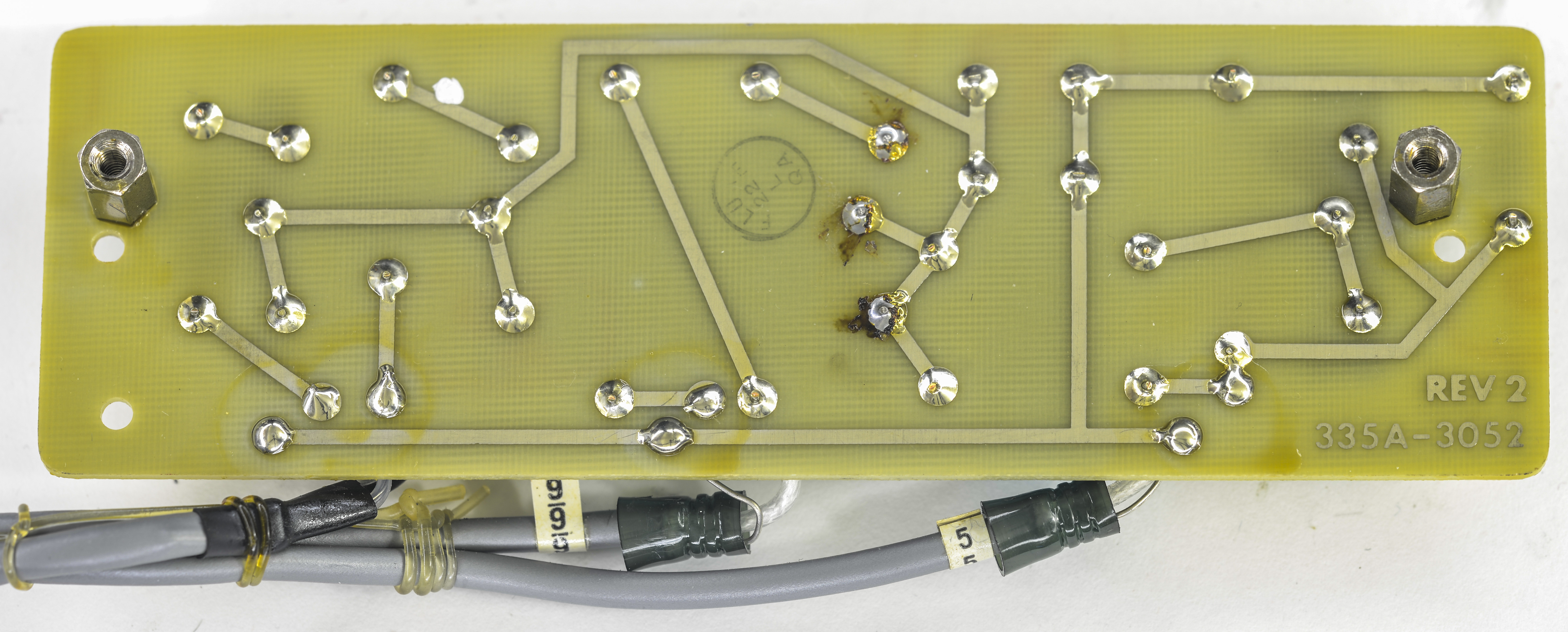
Reference board:
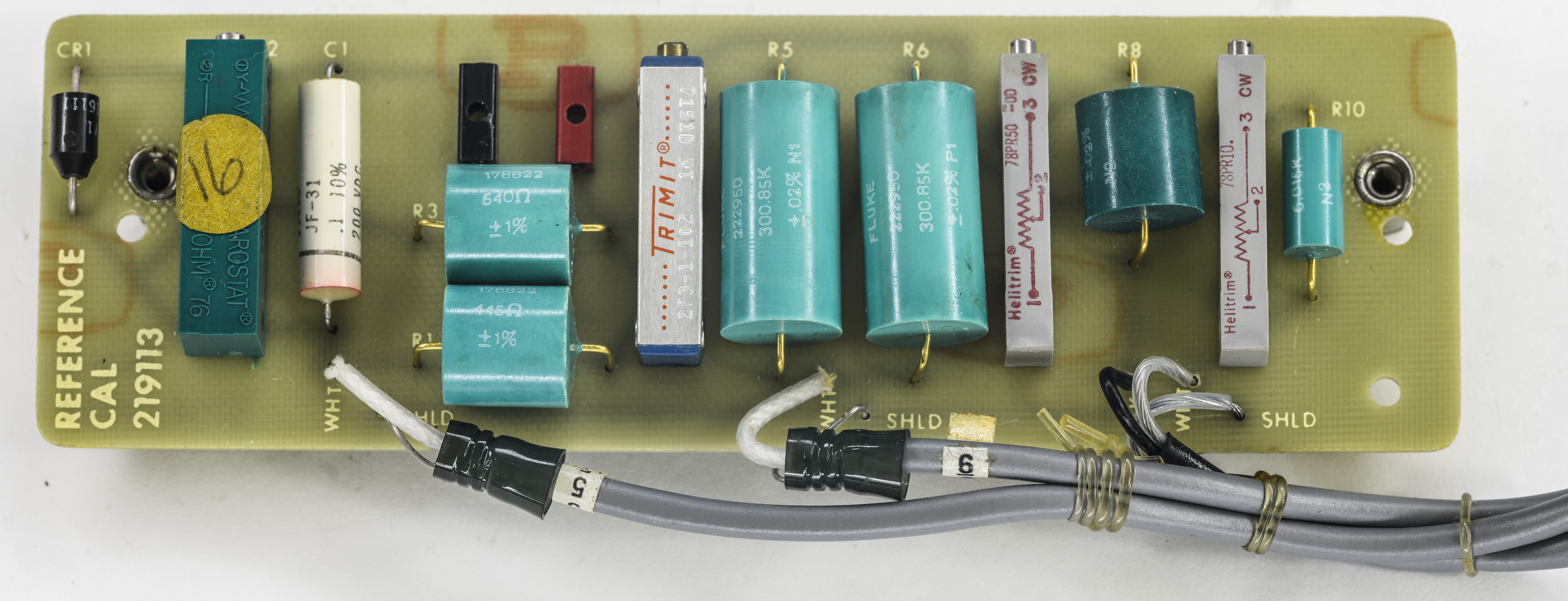
Resistors used on it:
| Qty | Fluke resistor code | Resistor case type | Manufacturer | Resistance value | Measured (DMM) | TCR | Power | Device |
|---|---|---|---|---|---|---|---|---|
| 2 | 226950 | Teal cylinder body, golden leads | John Fluke MFG. Co. | 300.85KΩ ±0.02% | kΩ | ±1ppm/K | ? | Fluke 335D |
| 1 | 178822 | Teal cylinder body, golden leads | John Fluke MFG. Co. | 540 Ω ±1% | Ω | ? | Fluke 332D | |
| 1 | 178822 | Teal cylinder body, golden leads | John Fluke MFG. Co. | 445 Ω ±1% | Ω | ? | Fluke 332D | |
| 1 | ?????? | Teal cylinder body, golden leads | John Fluke MFG. Co. | 60.17 KΩ ±0.02% | Ω | ? | Fluke 332D | |
| 1 | ?????? | Teal cylinder body, golden leads | John Fluke MFG. Co. | 6.015 KΩ ±0.02% | Ω | ±2ppm/K | Fluke 332D |
Table 2. Fluke resistors used on Fluke 332/335D reference trim board
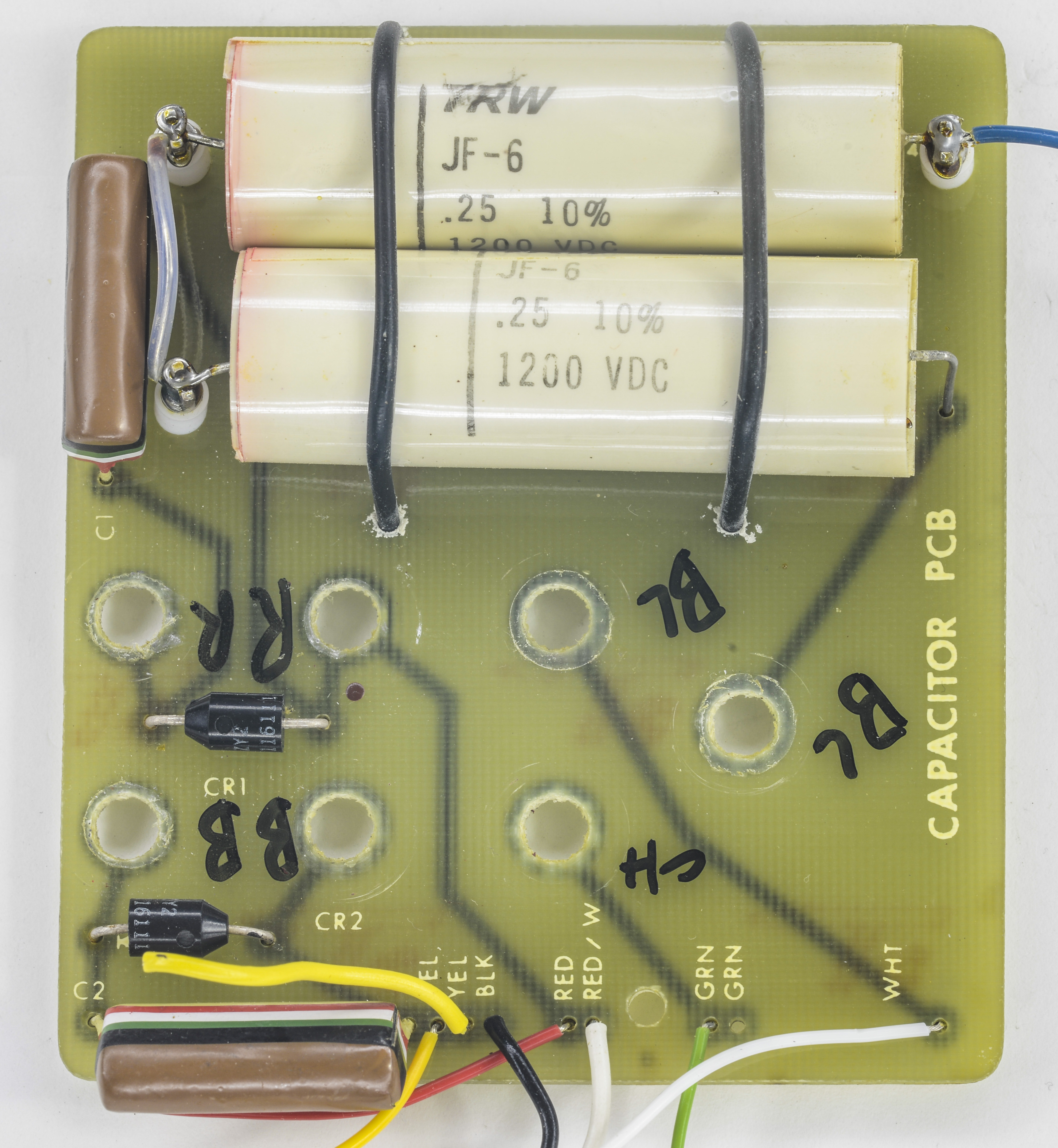
Capacitor board with pair of 1200VDC 0.25µF on Teflon standoff posts.
I’ll use these transformers to provide various power rails in my design.
Given my respect to Linear parts, perhaps we will see some ideal diode bridge with Linear LT4320-1 actions to be happening later.
Modified: Sept. 17, 2016, 11:07 p.m.