Contents
- Intro
- Disclaimer
- Project plan
- Parts source and assembly
- Initial test
- Test 2: TC correction resistor add
- Test 3: Reduction of oven temperature test
- Test 4: Op-amp kelvin connection test
- Test 5: Replacement of LTZ1000 chip
- Test 6: Thermal ramp and tempco measurement
- Summary
- UPDATE: Calibration offer for members with featured KX LTZ1000A PCB
Intro
Any electronics engineer who tried using technology on the edge of maximum performance possible will tell you many exciting stories. All of them likely to cover machine-like patience and attention to details required. Life is simple in 4½-digit world. You believe your Fluke 87V DMM without second thought, trust those values fully. Some hints of difficult life can start to reveal when switch to higher resolution instruments, like HPAK 34401 or Keithley 2000. And things can get expensive and take many hour-weeks real fast in state of the art 8½-digit zone. Similar eye-opening experience happen with me as well, during repair of rusty HP 3458A. Would I do it again if I had to choose? Yes, it’s a great (yet expensive) learning feat for anyone interested in analog electronics design. After all, digital is just a small subset of analog world, and it’s becoming more important today. Very high speed multi-GHz digital interfaces with their eye diagrams, crosstalks, coupling and noise become analog once again. So in the end of the day, it’s engineering wonder when you plug that USB 3.0 10 GHz storage disk into your computer or 4K UHD TV over 2 meter long 9.6 GHz cable and it just works.
But today we will not talk about design challenges, but rather have good time and enjoy story of one voltage reference build.
Disclaimer
The information contained herein is provided as a public service with the understanding that author, xDevs.com site, or any mentioned parties make no warranties, either expressed or implied, concerning the accuracy, completeness, reliability, or suitability of the information. This site page do not endorse any commercial provider or their products.
All data provided AS IS, and usage of information on this page is strictly for educational purposes. xDevs.com disclaims all express and implied warranties, without limitations.
Project plan
One of engineers doing precision measurement projects at home for own enjoyment contacted me while ago, asking some questions related to nanovolt-meter amplifier front-end and voltage references. His country of residence is Belarus, and I mention this because their customs are really strict about international shipments. Basically everything over 20 $USD mark is troublesome to import and due to high fees, often much more than package value itself. So his instrumentation desk was mostly using some old instruments, made in Soviet Union. We had nice talk about electrometer of his, which is an interesting bit of gear on its own.
On DMM front he has Datron Model 1271, 7½-digit DMM, smaller brother of Model 1281 which our other contributor, Todd, had covered well before. Quickly talk was biased towards voltage references. Buying famous Linear LTZ1000 was not an easy option due to shipping/customs troubles, even worse considering existing lack of access to calibrators or metrology labs nearby. Even though this 1271 is fine instrument, it was not recently calibrated and absolute accuracy was unknown. Since this situation was very familiar for me few years ago, I decided to give a hand and help this engineer to “import” verified DCV standard into his home hobby lab. Agreement to build one KX LTZ1000 voltage reference was made.
Buy some parts, put on PCB with less than 30 components, measure the output and send the board thru mail. Sounds easy job, no rocket science, right?
Parts source and assembly
To make this whole little project more interesting for me, I wanted to try two new ideas, which were not attempted before in previous builds.
A. Try 1KΩ/13KΩ hermetic resistor network (custom Vishay VHD200, oil-filled ±3ppm/K two-resistor network) with 0.05% matching. This might give some interesting data, if tightly coupled oven setting thermal point resistors help to improve tempco of the reference. Only few LTZ1000-based designs, such as ones in Datron 4708/480x/1271/1281/49xx instruments are using resistor networks, likely due to high cost. Modern result of those is Fluke 8508A, which have ceramic laser-trimmed TaN-network on its LTZ1000A reference module.
B. Try alternative chopper amplifier, Analog Devices ADA4522-1 instead of my usual Linear LTC2057. Both op-amps are rather unnecessary for this particular circuit, as noise of LTZ1000 zeners itself is magnitudes higher than opamp contribution. But maybe other issues pop up with AD chip.
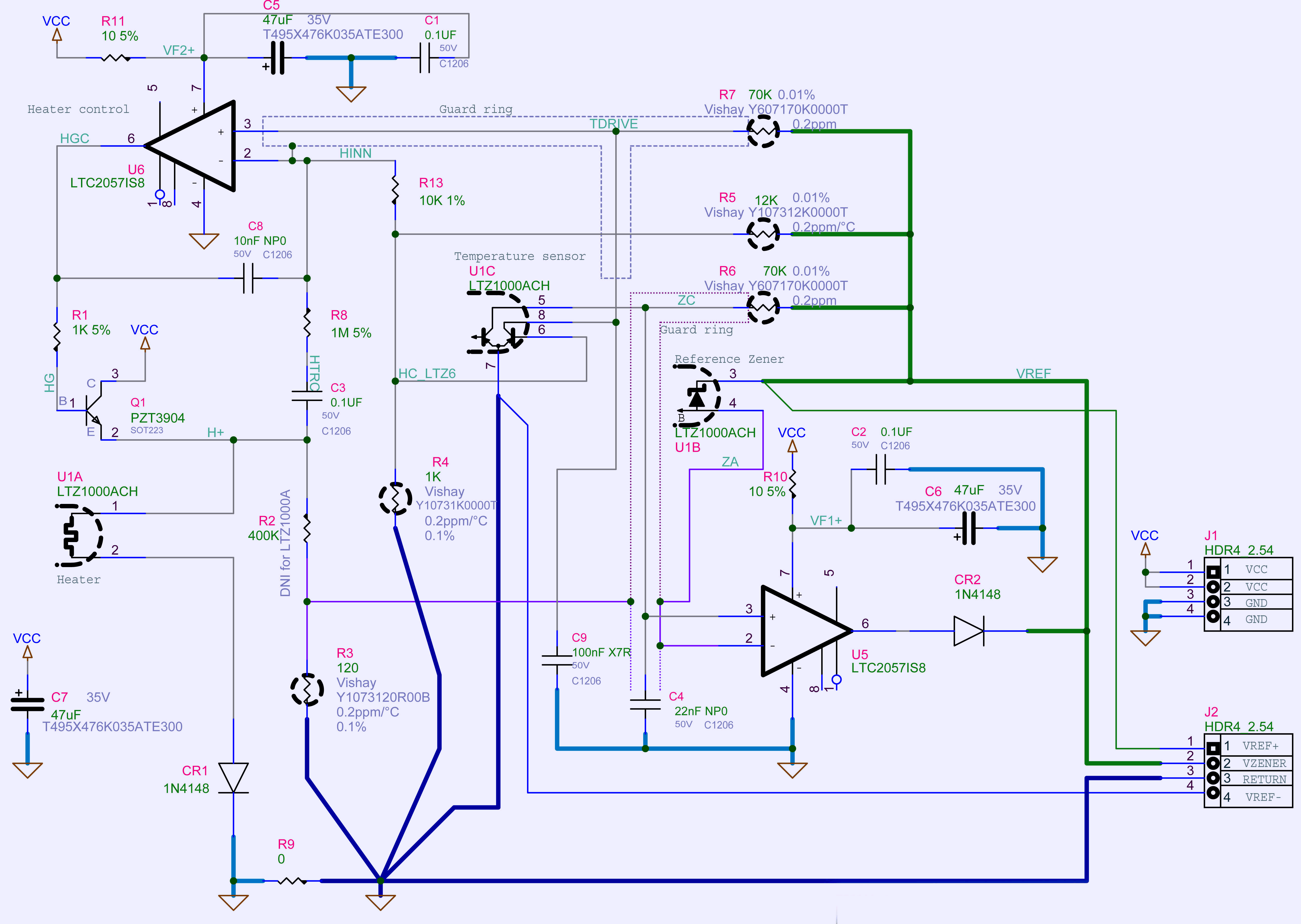
Schematics 1: xDevs.com KX voltage reference (Rev.B02) reference
As a base my latest Rev.B02 version of KX LTZ1000 PCB is used. This module 4-layer FR4 ENIG-plated PCB use two single op-amps in SO-8 package, accepts +10-20VDC input, feature two Maxim MAX6610 temperature sensors and compact in size, making it suitable for integration into various instruments and projects. It does NOT provide 10V, but gives direct +7.xxxxxx VDC from the LTZ1000 using kelvin connection wiring. It does not have current drive capability or overload protection, so it’s not quite a finished DC Voltage standard, but a core building block.
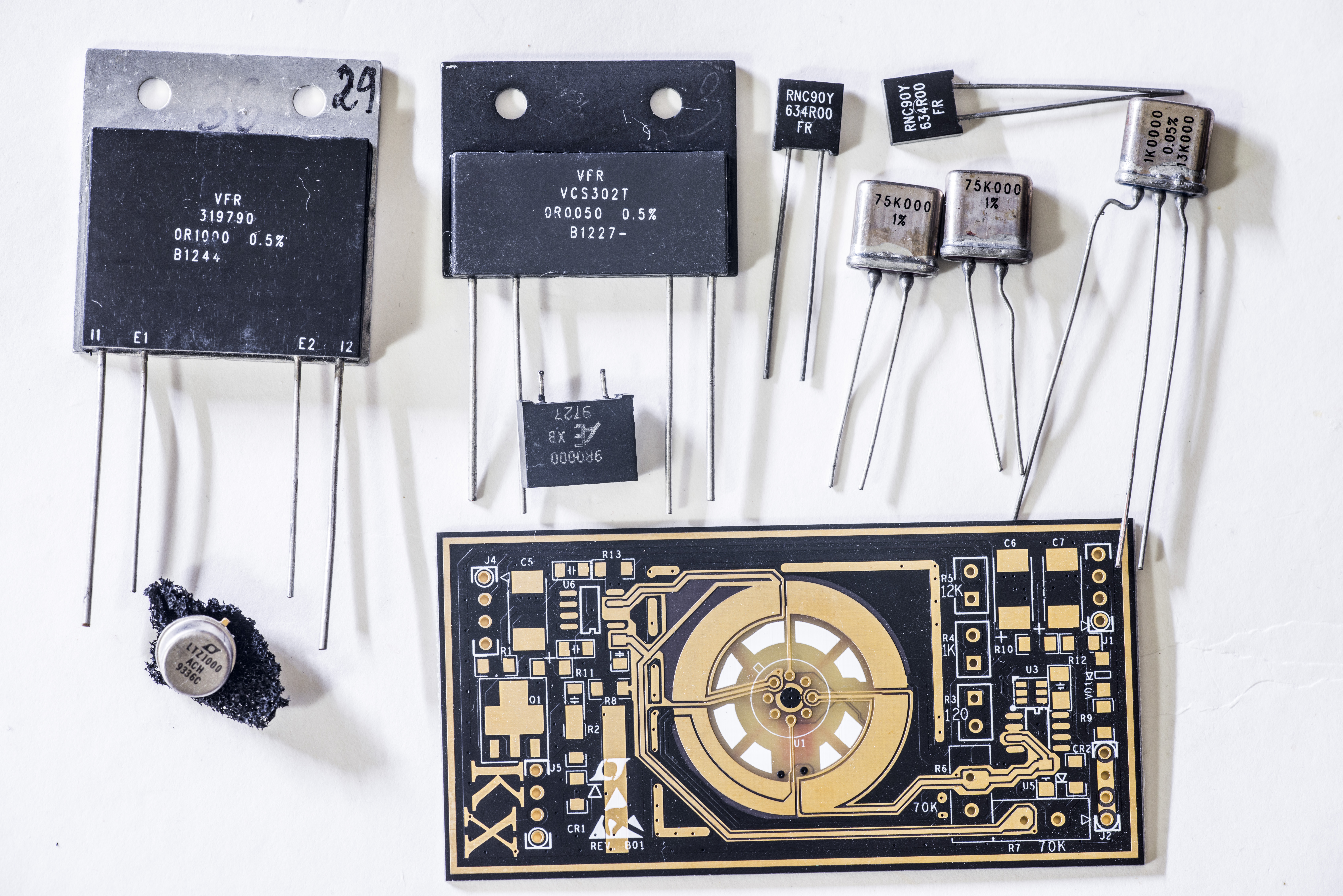
Image 2: Foil resistors, LTZ1000ACH chip and xDevs.com KX board
Latest B03 version of this PCB is now an open-source design, was published by one of EEVBlog members and is available to order from OSH Park for around $17 USD/pc.
Rest of the circuit resemble reference design from datasheet, with use of Vishay hermetic VHP resistors for 120 Ω and 75 KΩ. I tried to keep cost low for this case, so did not order there precision stable resistors from Vishay PG, but got them from Chinese eBay seller. Four resistors cost was 120$ USD, so it’s half or more of what official VPG cost could be. Of course, as result – no warranties, no returns if things go salty.
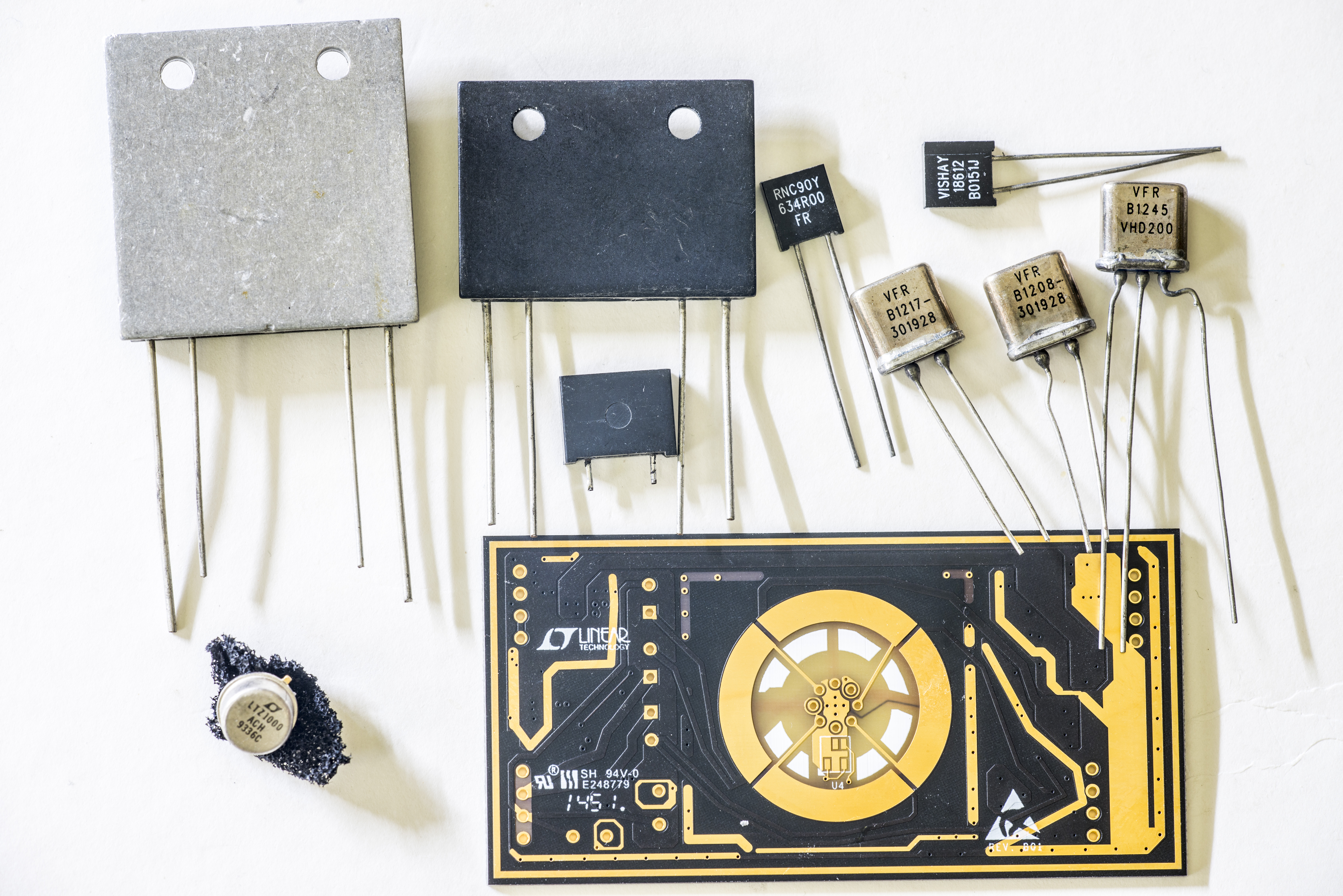
Image 3: Bottom side
Before soldering resistors down into circuit, I did a quick measurement to check that they don’t give some wild deviations.
| Resistor | Spec | Datalog | Deviation | TCR est |
|---|---|---|---|---|
| Custom VPG 120Ω, R3 | 120Ω 0.1% | 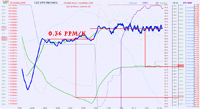 |
-0.8 ppm – +26.4°C | 0.36 ppm/K |
| VPG VHD200 1 KΩ, R4 | 1 KΩ 0.05% | 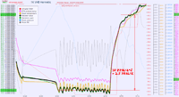 |
-75 ppm – +24.0°C | 2.5 ppm/K |
| VPG VHD200 13 KΩ, R5 | 13 KΩ 0.05% | 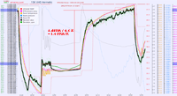 |
-5 ppm – +24.3°C | 1.4ppm/K |
| Custom VPG 75 KΩ, R6,R7 | 75 KΩ 0.5% | -14.3 ppm – +26.7°C | 0.5 ppm/K |
Table 1: Test results on resistors
Measurements over all resistors was made using NPLC 100, with OCOMP ON, DELAY 5 and AZERO ON settings. Resistors were mounted directly on DMM’s terminal ports to avoid unnecessary thermal stress from soldering wires.
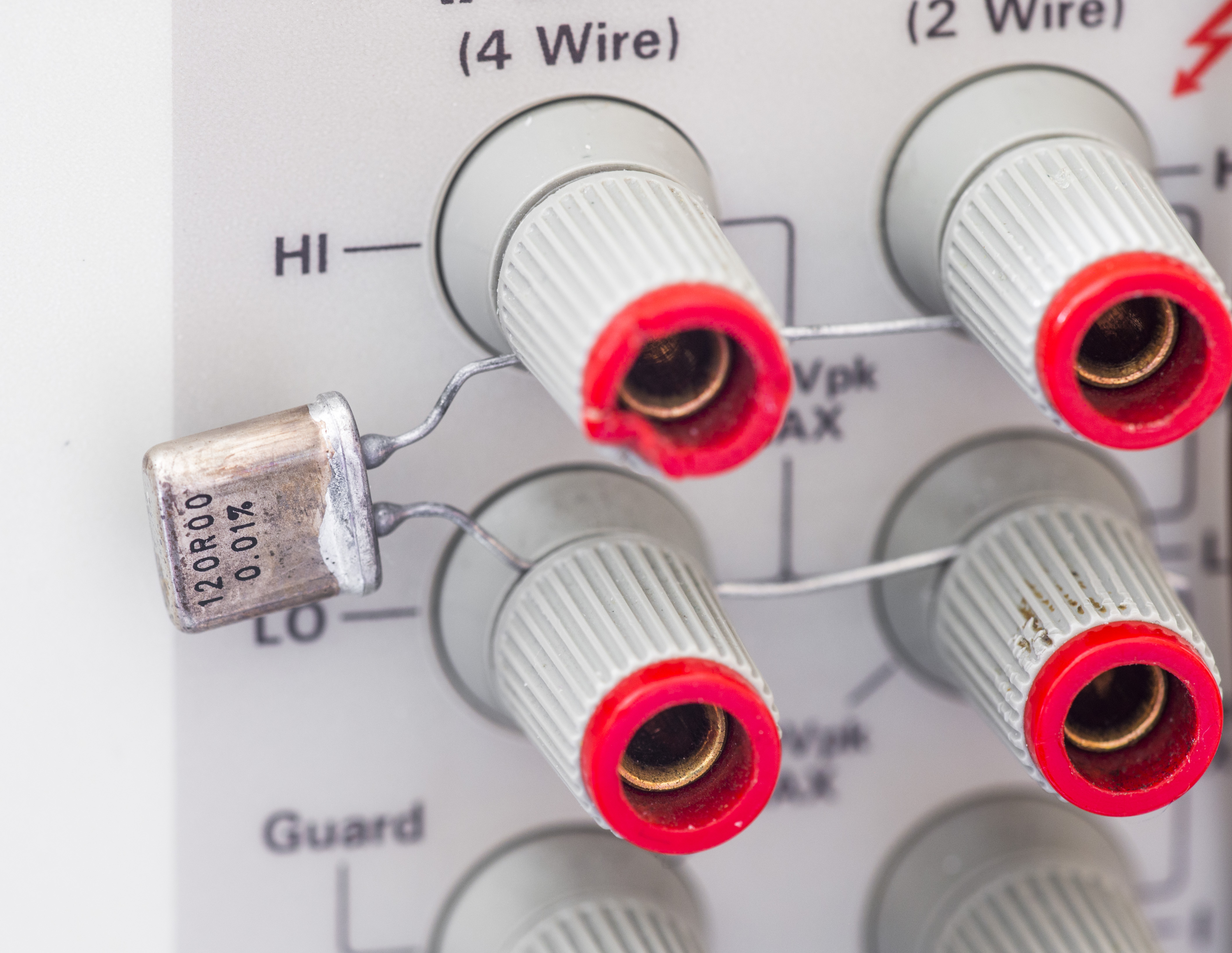
Image 4: 120 Ω resistor on HP 3458A DMM terminals for 4-wire
Results looks good, and resistor markings are legit and genuine, so I’m more confident now that these are genuine Vishay PG parts.

Image 5: Prepare parts for assembly
First small SMD parts were soldered on, and checked. Used LTZ1000ACH chip, manufactured 36 week of 1993 was soldered on, with maximum soldering time around 0.5 second per pin, to reduce excessive heating. Foil precision resistors were populated last. I used ERSA ICON soldering station with tip temperature set at +260 °C.
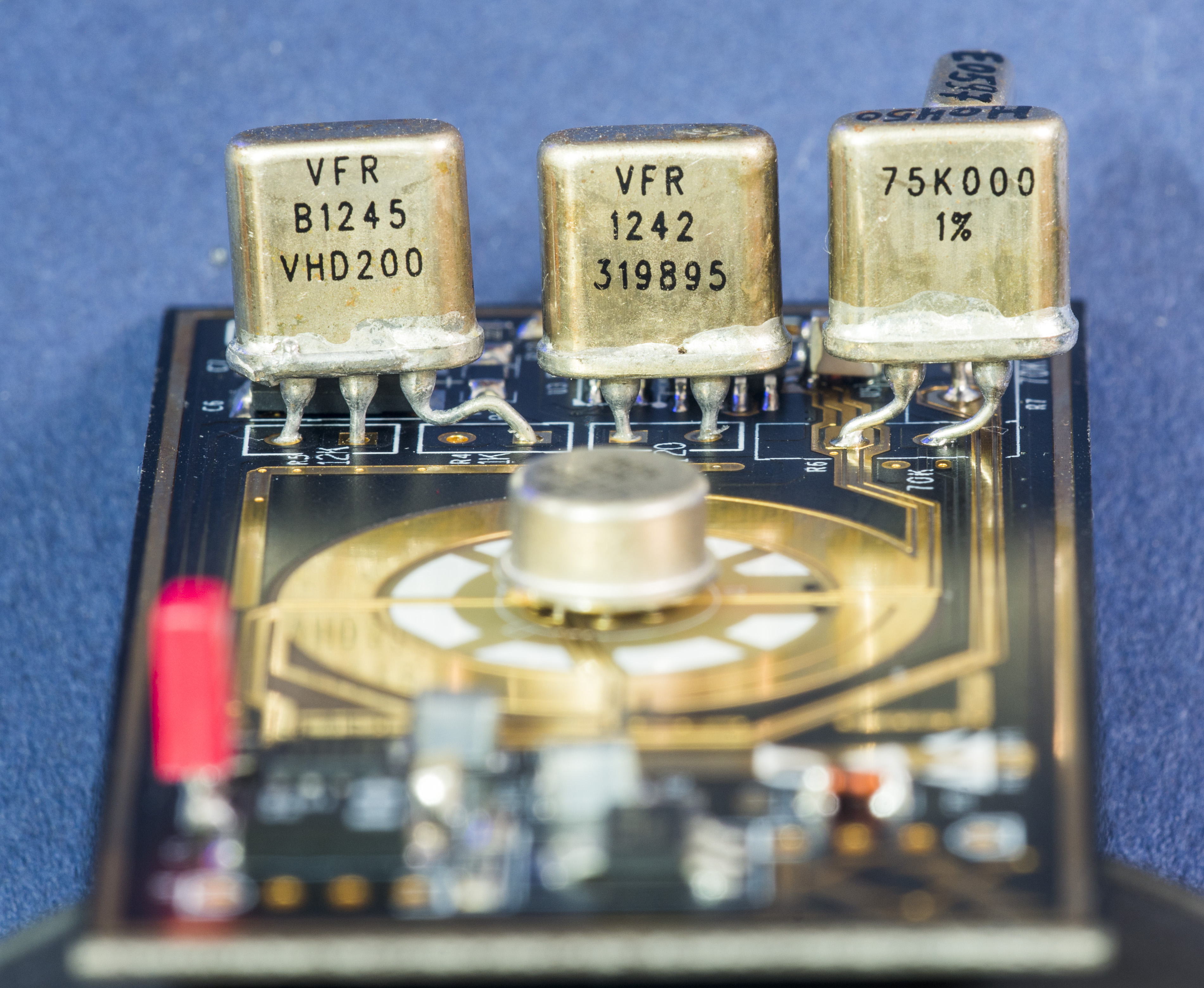
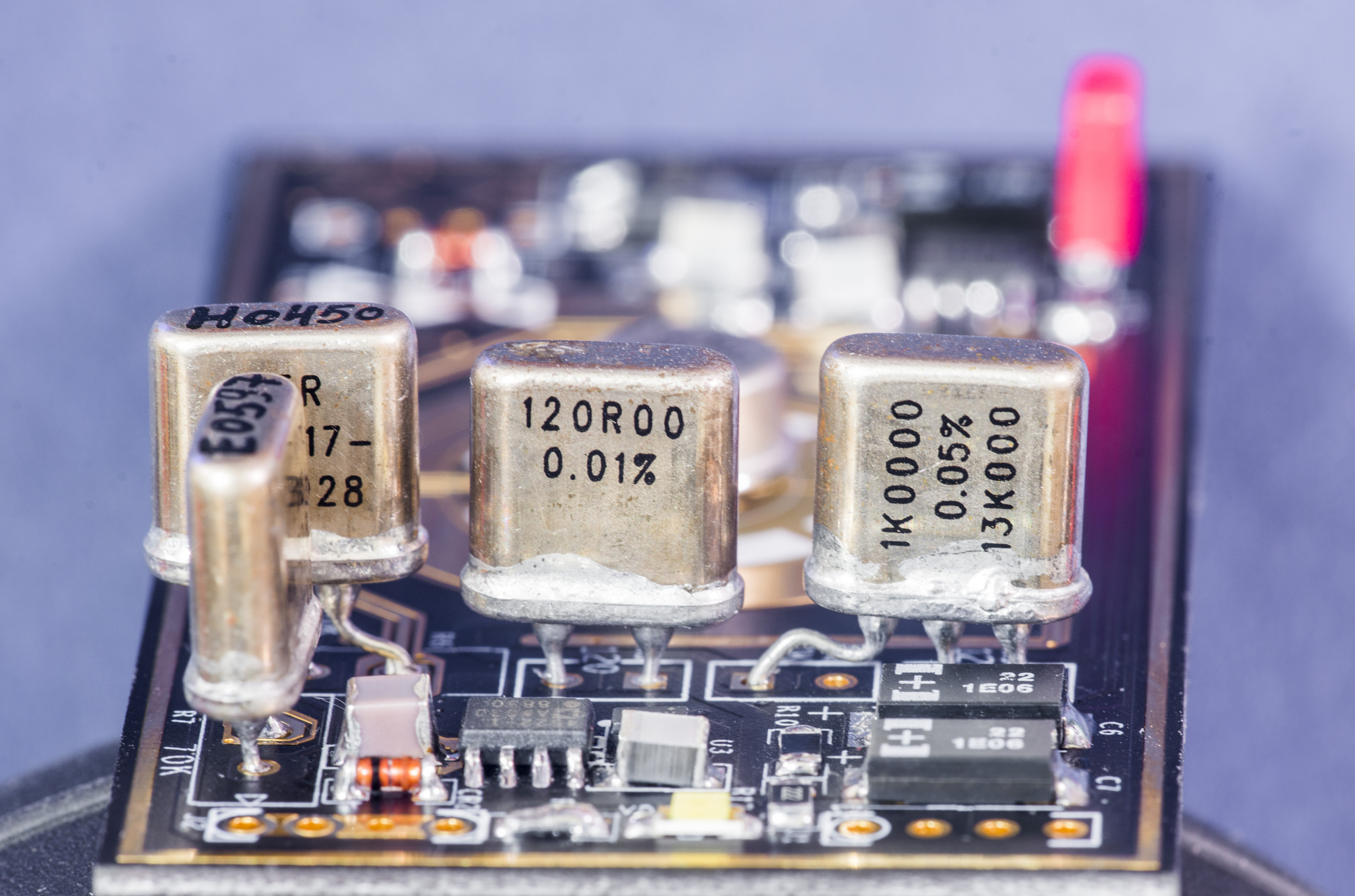
Image 6-7: xDevs.com KX voltage reference assembled, resistors
Assembled module ready for the initial test. There is no much to say about it. Details and caveats around construction of LTZ1000-based reference were explained in better detail in KX design article.
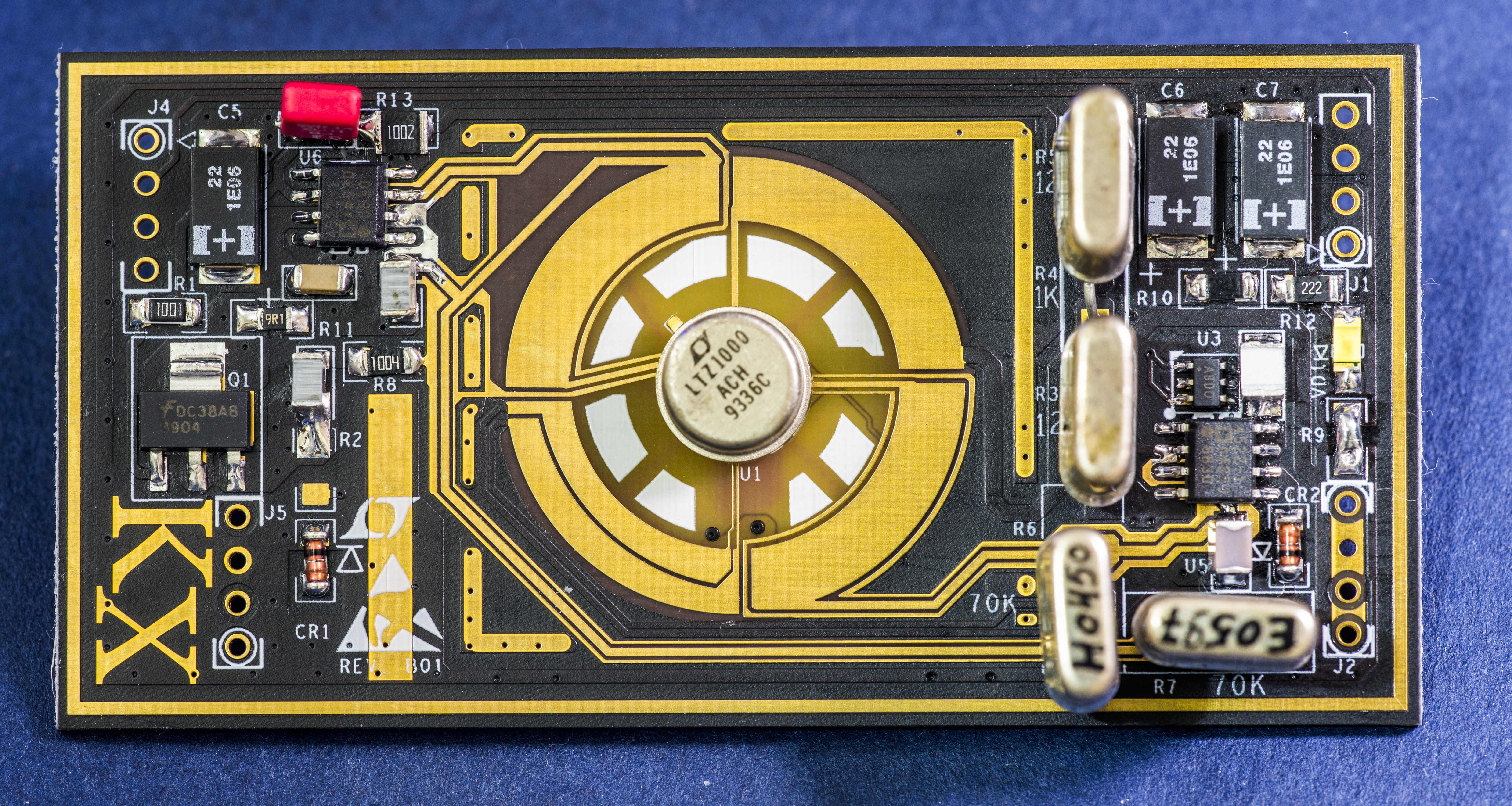
Image 8: Ready for test with LTZ1000ACH chip
All capacitors on signal path are film-type to avoid piezoelectric voltage generation due to mechanical stress or vibration. Board was cleaned with clean IPA from soldering flux and residues as much as possible. Avoid ultrasonic bath cleaning when module is populated with LTZ1000 reference and foil resistors, to avoid stress to these parts.
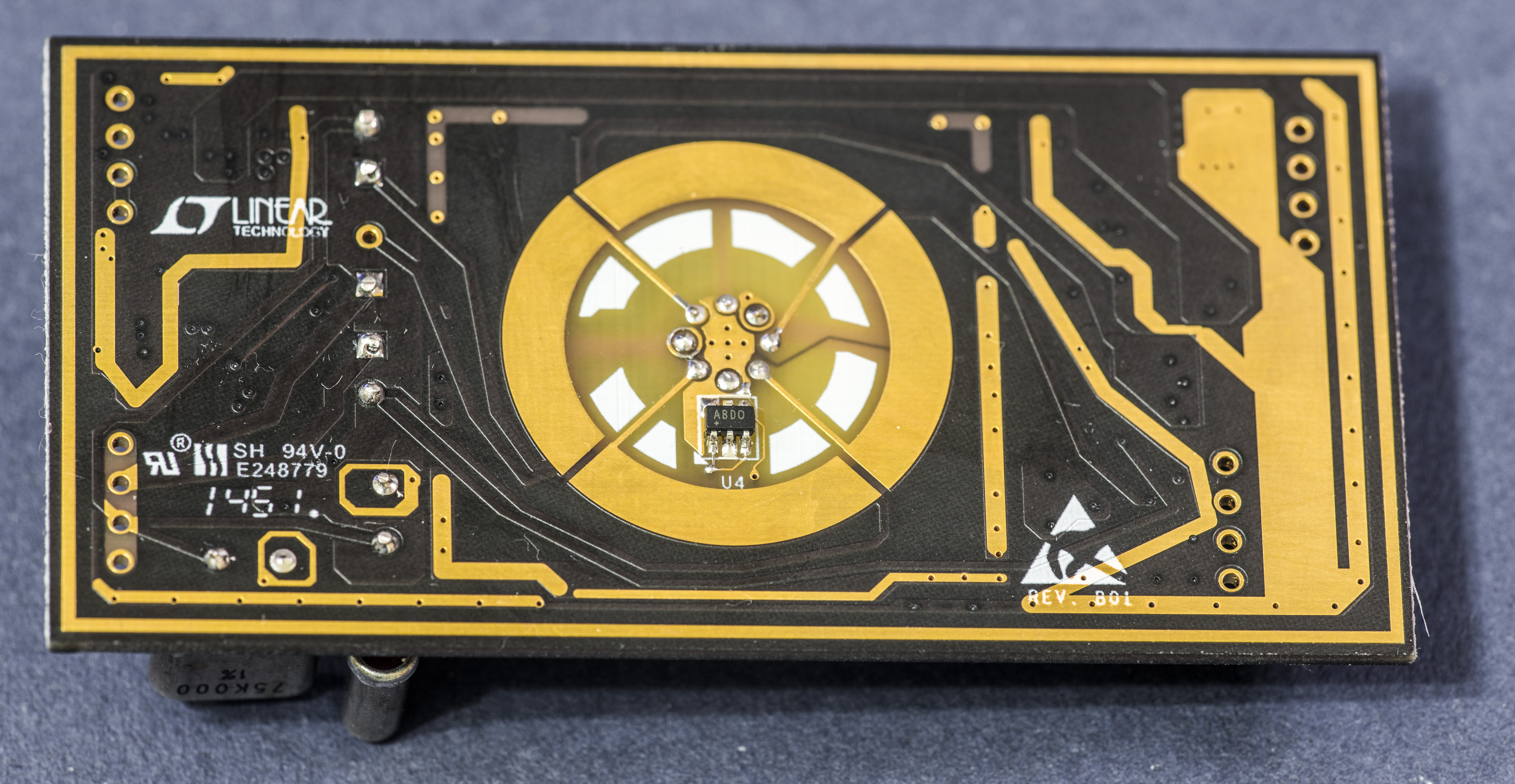
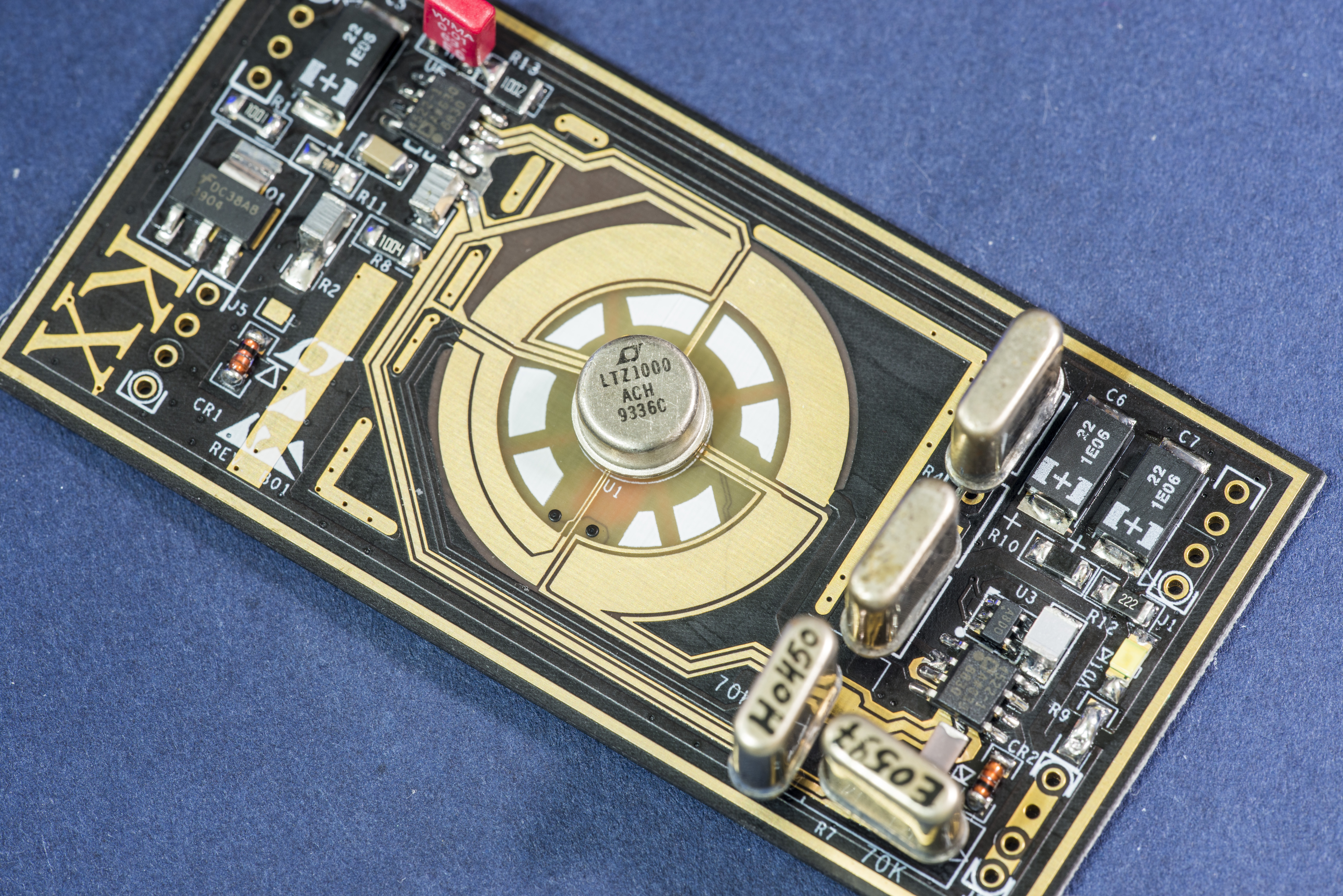
Image 9-10: xDevs.com KX additional photos
Digital temperature sensors are populated but not used. They have separate +5 VDC input connector, so they are not powered in our experiments.
Let’s put module into plastic jar to avoid airflow around it, wire it to voltage supply (Keithley 2400 SMU, set to +15 VDC 100 mA source) using copper single-strand UTP twisted part cable and give it a go.
Initial test
Before we jump in to actual test data, it’s important to have good confidence in measurement equipment and lab tools, to make sure that any unexpected phenomenon comes from device under test, not the equipment itself. This also means that even brand new, freshly calibrated equipment must be verified and tested before any solid conclusions to be made.
To satisfy this requirement, I had chance to calibrate my older LTZ1000ACH/LTZ1000CH based references against 15-day calibrated Fluke 732B DC Voltage standard in mid-August 2016. Two Keithley 2002 8½-digit multimeters we calibrated to same Fluke reference same time, to act as transfer standards and guard-banding tools. I used these DIY standards and DMMs to transfer absolute DCV voltage into my verified and improved HP 3458A, which confirmed to be stable by daily 24/7 operation and monthly checks to both hot and cold external LTZ1000A modules. As a result, I have high confidence that absolute DCV accuracy in my home lab is within ±2 ppm.
Now with verified gear, initial test conditions are fairly simple. Purpose of first test is to make sure of reference normal operation, and measure initial voltage, drift if any and stability. Output should not deviate more than ±1 ppm over few days period, and temperature coefficient (change of output voltage from change of ambient temperature) should not exceed ± 0.1 ppm/K.
Power supply : 12VDC 2A cheap mains power brick.
Measurement : HP 3458A, calibrated August 31 to ±2ppm DCV.
Ambient condition : Ambient room temp with aircon, ±3 °C. Monitor by BME280 sensor
Datalogging : Raspberry Pi with linux-gpib + python + NI GPIB-USB-HS
Analysis : D3.js plotting library on xDevs.com site
Below are pieces of python code to talk with instrument and configure for measurement.
    def init_inst(self):
        # Setup and config HP 3458A
        self.inst.clear()
        self.inst.write("PRESET NORM")
        self.inst.write("OFORMAT ASCII")
        self.inst.write("DCV 10")
        self.inst.write("TARM HOLD")
        self.inst.write("TRIG AUTO")
        self.inst.write("NPLC 100")
        self.inst.write("AZERO ON")
        self.inst.write("NRDGS 1,AUTO")
        self.inst.write("MEM OFF")
        self.inst.write("END ALWAYS")
        self.inst.write("NDIG 9")
        self.inst.write("DELAY 0")
HP DMM takes continuous reference output voltage samples with NPLC 100 speed, Auto-zero enabled on base 10VDC range.
    if ( (prev_t < (temp - 0.2)) or (prev_t > (temp + 0.2) ) ):
	print ("Temp change >0.2c, run ACAL DCV")
	meter1.acaldcv()
	prev_t = temp

	with open("ltzsn18log.csv", "a") as osf:             # Write calibration constants data to separate file
	    osf.write (time.strftime("%d/%m/%Y-%H:%M:%S;"))  # Write date/time
	    meter1.inst.write("CAL? 72")                     # Cal value 72
	    data = meter1.inst.read()
    	    osf.write ("CAL? 72 = %s " % data)
	    osf.write ("TEMP = %f\r" % temp)
Python application also measure ambient temperature on each sample, and if temperature changes more than ±0.2°C from previous value, ACAL DCV procedure is run to reset own HP 3458A temperature coefficient errors. Since my HP 3458A using very stable LTZ1000CH module with reduced oven temperature, it’s essentially comparison of our DUT LTZ module versus internal one in the meter.
Every 50th sample HP 3458A also requested for internal temperature measurement via exectuting TEMP? command.
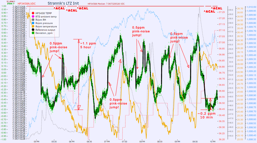
Image 11: Results from Run 1. Click for live data
Yes, it’s alive, measuring output voltage +7.067329 VDC ±2 ppm.
And how we looking here? If this would be integrated reference, such as band-gap reference on internal DAC/ADC references, result noise 1.1 ppm could be simply miraculous. However for top-end ovenized buried zeners, which for Linear LTZ1000 is extremely bad. To remind you specifications, this circuit should be able to provide 0.05 ppm/K drift rate and approximate noise levels of 1.2 µVpk-pk. We are getting 7.4 µV instead for noise. Tempco is also horrible, about 1 ppm/K, 20 times worse than expected!
Test 2: TC correction resistor add
For second test we work on mistake and try to address issues on data we saw earlier.
- Improve stability of ambient temperature, so we can isolate TC issue for now.
- Test with 394K R2 populated, even though we use LTZ1000ACH and this compensation not needed.
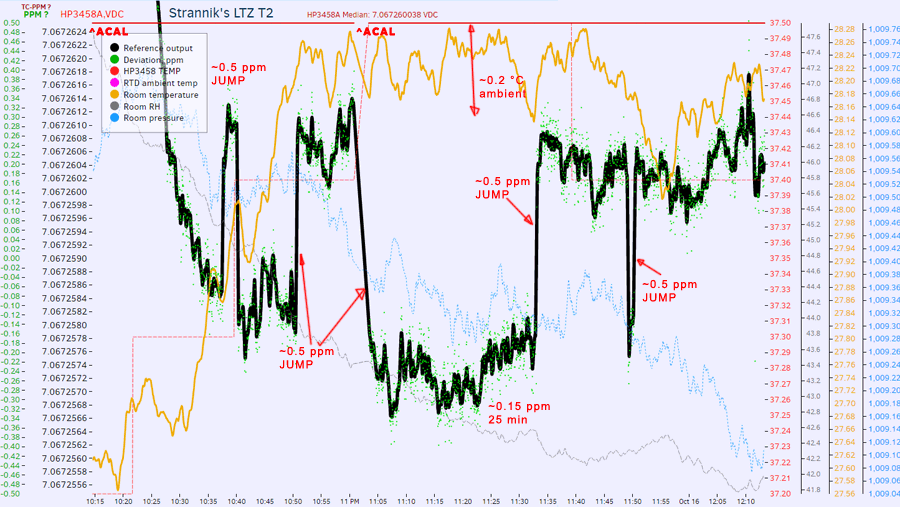
Image 12: Results from Run 2. Click for live data
Output voltage changed from +7.067329 to +7.067259 VDC, which is -9.84 ppm after adding R2 resistor in circuit. Jumps are still there and were not affected.
Some of our readers not familiar with LTZ1000 performance may scream at me right now, how you know that this is bad result. Vertical ppm scale (left green scale is ±1ppm, which is 0.0001% accuracy!) is blown out to make this amazing reference look bad, you say?
Alright, I hear you. And here’s the answer, same condition measurements with good and checked LTZ1000CH voltage reference module, using same schematic and same PCB, just different parts. Horizontal time span of graph below is 11 hours.
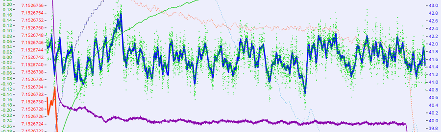
Image 13: Reference test result on another LTZ1000CH KX module
See, noise of this good module is mere ±0.1ppm, no random jumps or other weird crap, everything nice and stable. That’s how you want it, not jumpy-jumpy  . Of course if you reduce your accuracy demands to 0.002%, everything looks nice even with jumps.

Image 14: Reduced accuracy data to 20ppm span
But it does not make sense to pay 250$ USD for such accuracy, so let’s continue our journey.
Test 3: Reduction of oven temperature test
Alright, how about reduce LTZ1000ACH oven temperature inside chip, by changing 13KΩ resistance on divider to lower value? Let’s see
Fluke 300KΩ -1 ppm/K wirewound resistor was soldered in parallel with 13KΩ on board, and test was repeated.
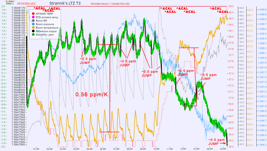
Image 15: Results from Run 3. Click for live data
Tempco is ~0.6ppm/K (still 10 times worse), but jumps are standing strong. Output voltage changed from +7.067329 to +7.064808 VDC, which is -346.8 ppm. You can see how much temperature setting affects the output, so that’s why important to have 1K/13K tempco track as good as possible.
Test 4: Op-amp kelvin connection test
Here I had cut separate trace between Pin 2 U5 opamp and R6 resistor, and jump-wired connected guard ring point directly at pin 4 of LTZ1000ACH chip. This makes almost Kelvin-like connection for all inverting node connections. Why I did so? Hm, intuition? :)
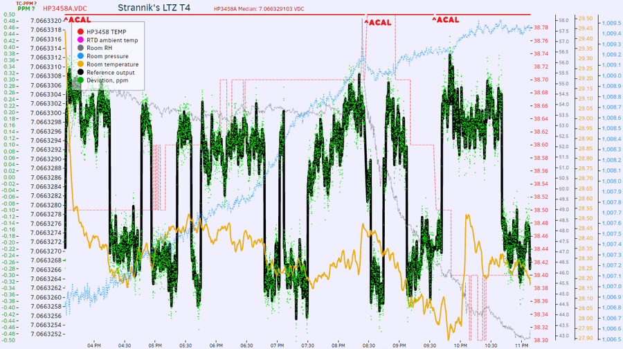
Image 16: Results from Run 4. Click for live data
Jumpie-jumpie is still there. Noise of LTZ chip noise itself is riding on top of those jumps. Overall it looks nice and stable, just the pesky jumps, which is pink-noise of zener junction. Output voltage changed from +7.064808 to +7.066329 VDC, which is +215 ppm.
Test 5: Replacement of LTZ1000 chip
Now, if we dig a bit into physics, this jumps are nothing but pink-noise, likely caused by zener effect breakdown is due to quick bursts of electrons going thru thin junction on high voltage. This breakdown is just about 7 volts, and that’s close to out near 7.06V output of zener inside this LTZ1000ACH. So it does look that no external component tweaks could fix this… Let’s see on test result of TEST RUN 5:
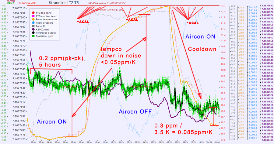
Image 17: Results from Run 5. Click for live data
It’s good now! What is the magic? There is none, actually, just engineering. Now we getting some solid data. Noise over multiple hours is just around 0.2ppm, which translates into around 1.2 µVpk-pk, initial tempco evaluation from +26.6 °C to +30.5 °C unable to reveal any tempco clearly, no large jumps either.
Okay, now I’ll tell you something that I knew from the start, but did not tell first, to make this entire feat interesting. This original LTZ1000ACH chip, which was used in Tests 1-4 is one from original HP 3458A’s A9 DC reference board, which I bought last year from eBay for 100 USD. My HP 3458A come without this reference module, so I had to source a replacement, instead of bodging own reference inside meter.
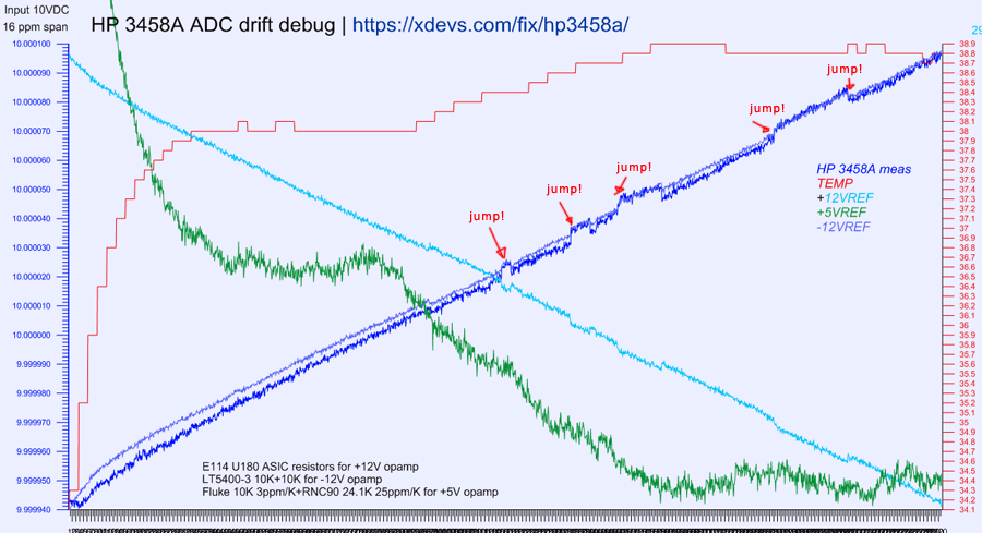
Image 18: Test data from HP 3458A repair, with this very same LTZ1000A
The very same jumping pink-noise behavior was observed on readings when it was used in HP 3458A meter as well. After replacement of LTZ1000A chip with other old aged LTZ1000CH jumps are gone, and this jumpy LTZ1000A chip just sit on shelf for half a year or so. So we know what to do now, get rid of it (again) and solder other chip instead.
Also note much higher voltage of this LTZ1000CH chip. It’s +7.163752 VDC, whole 100mV higher than previous jumper. To make sure I don’t trick you with my rusty HP 3458A, additional measurement log with calibrated Keithley 2002 meter was added on this test too. You can see both HP and Keithley DMM agree on measurement within 0.02 ppm! (averaged). There are no math offsets, relative math or any other funny cheating. RAW DSV-data file is /datashort/str5_ltz_3458_nplc100_tin.csv.
Pay attention, this is also 23 hour test, longer than previous logs.
Test 6: Thermal ramp and tempco measurement
Thermal chamber setup
To perform temperature tests and measure temperature coefficient (which shows how much voltage on the output will change with temperature variation) we need thermal chamber. Most simple chamber is an insulated box with heater attached to it, so internal box temperature can be adjusted, without direct dependence on ambient temperature. Since our module is low power device, around 0.5W, we can get away with TEC element as active heater. As bonus TEC is also able to pump heatflux away from chamber, cooling our DUT below ambient temperature.
Insulation required reducing heat loss and effect of ambient temperature change on internal temperature. This means that we will spend less power to adjust and maintain set temperature in the box.
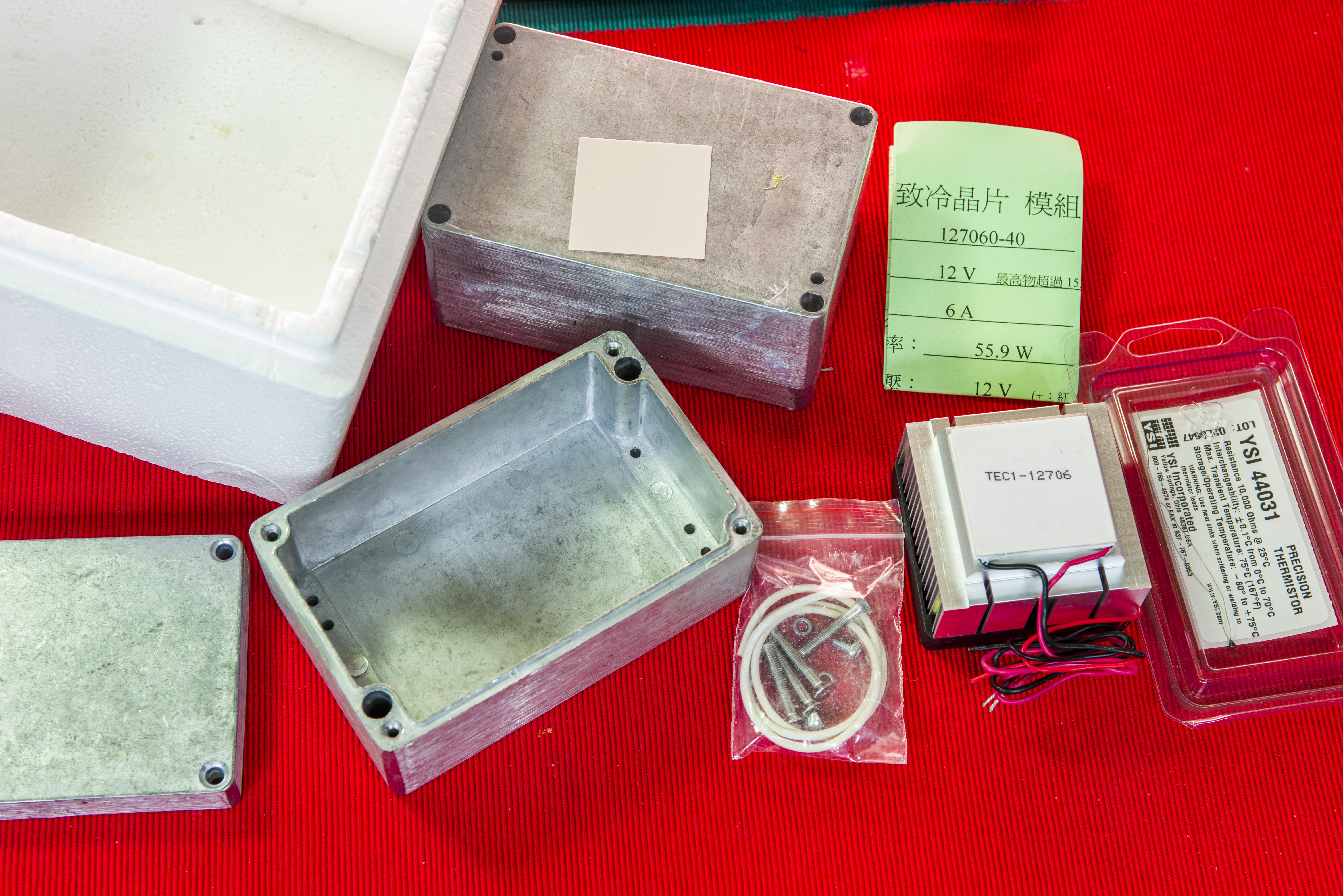
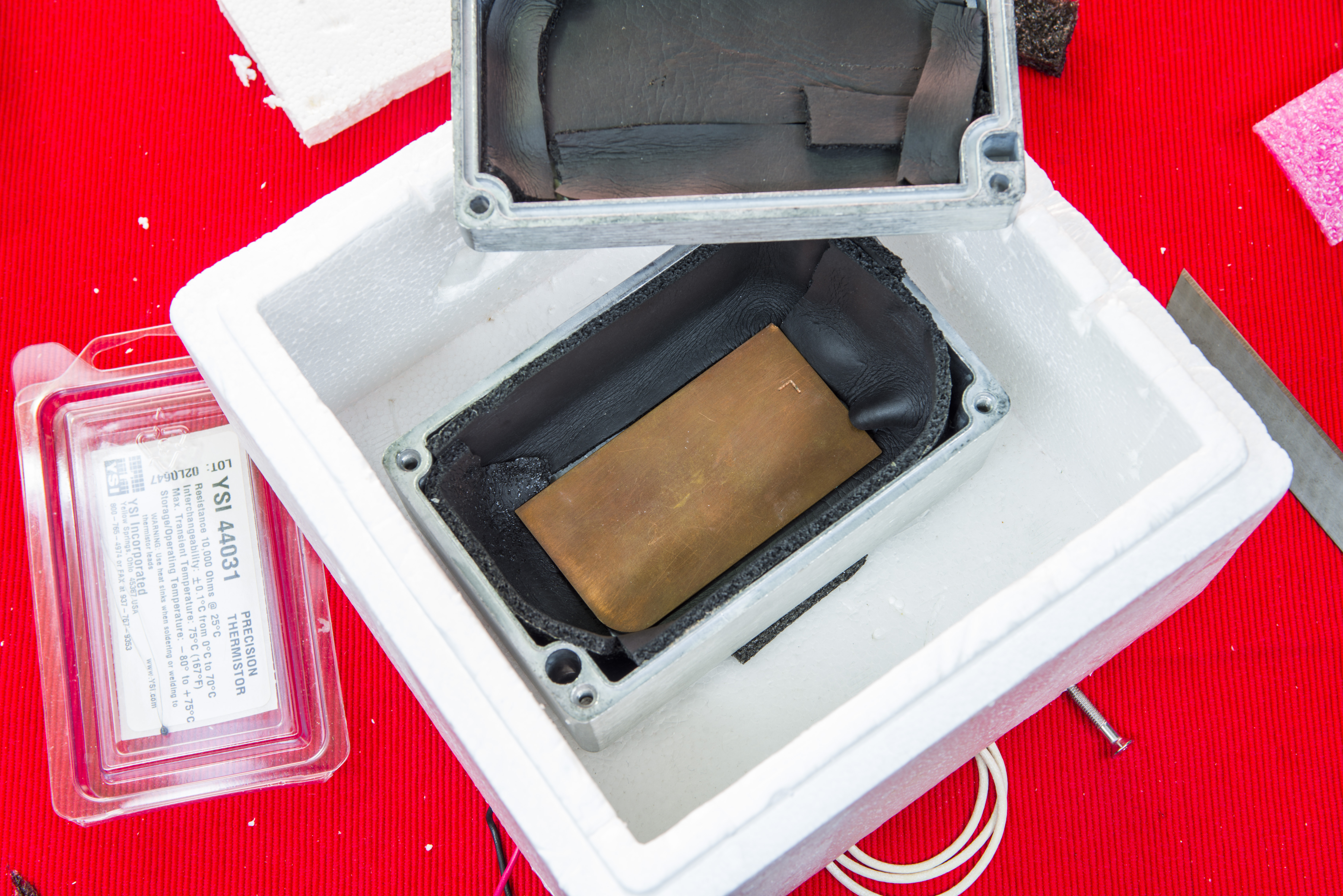
Image 19-20: Parts for DIY thermal box
All parts required to build the box are shown on photo. Metal air-tight die-cast box will be used as internal chamber for DUT. Styrofoam box from ice-cream shop will act as insulation barrier, and some HVAC insulation foam is used internally to decouple DUT from rapid temperature changes. Simple extrusion aluminum heatsink with DC fan mounted on hot side of TEC element to remove unwanted heat and keep system stable.
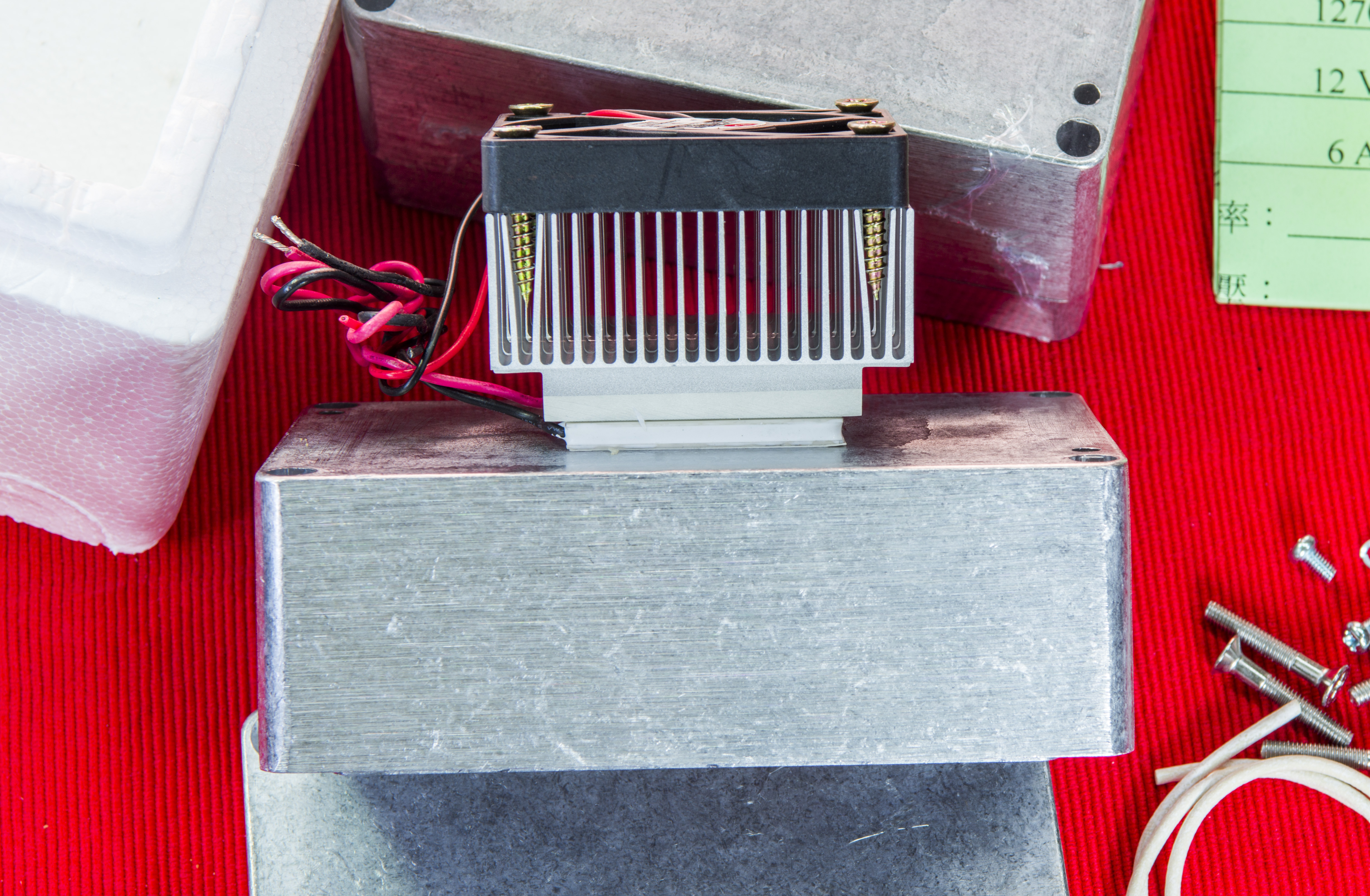
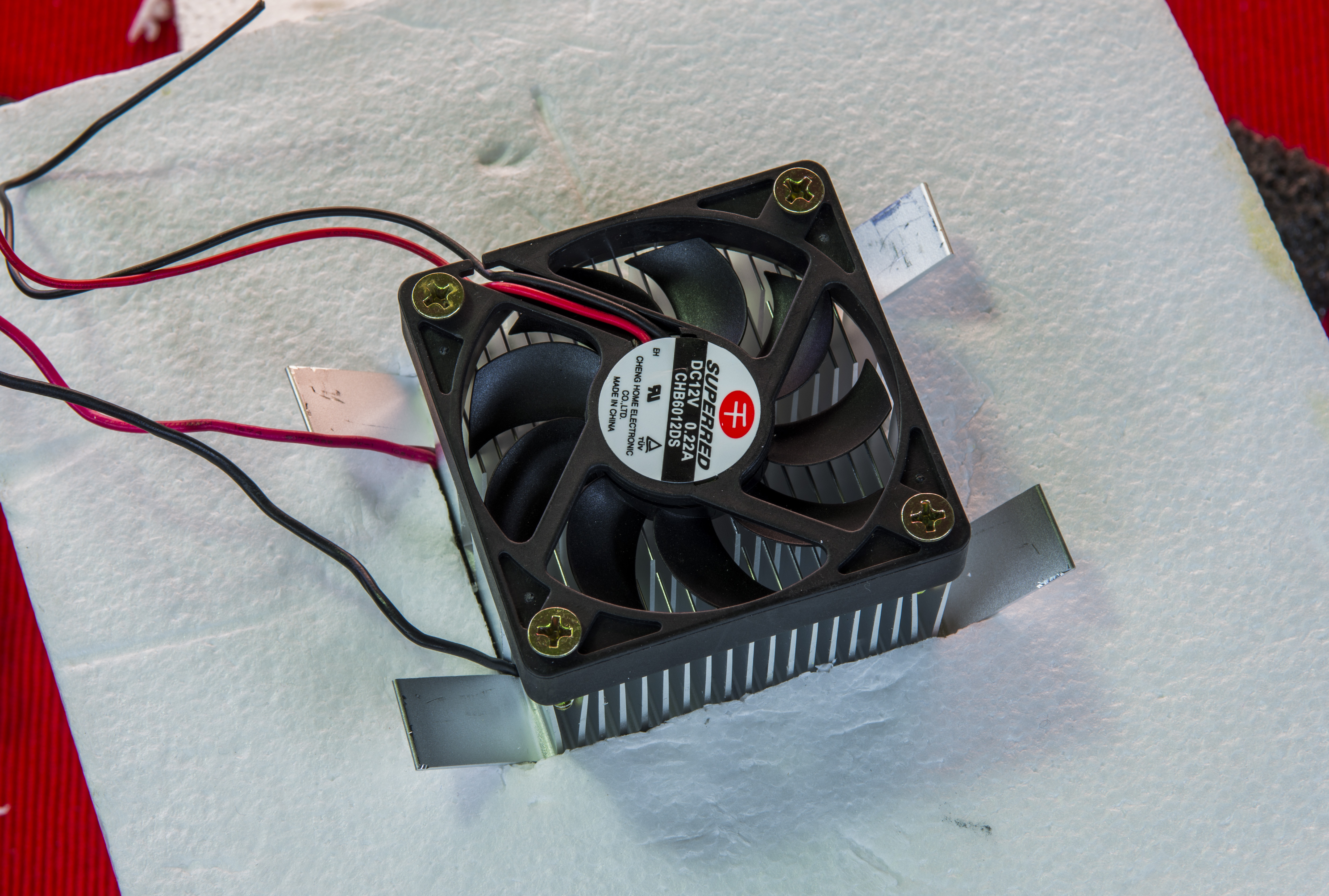
Image 21-22: Fansink and mount on the box
Corner heatsink fins were bent outwards to keep it fixed and tight in Styrofoam insulating box. All air gaps between TEC heatsink and box are filled with foam to reduce thermal leakages.
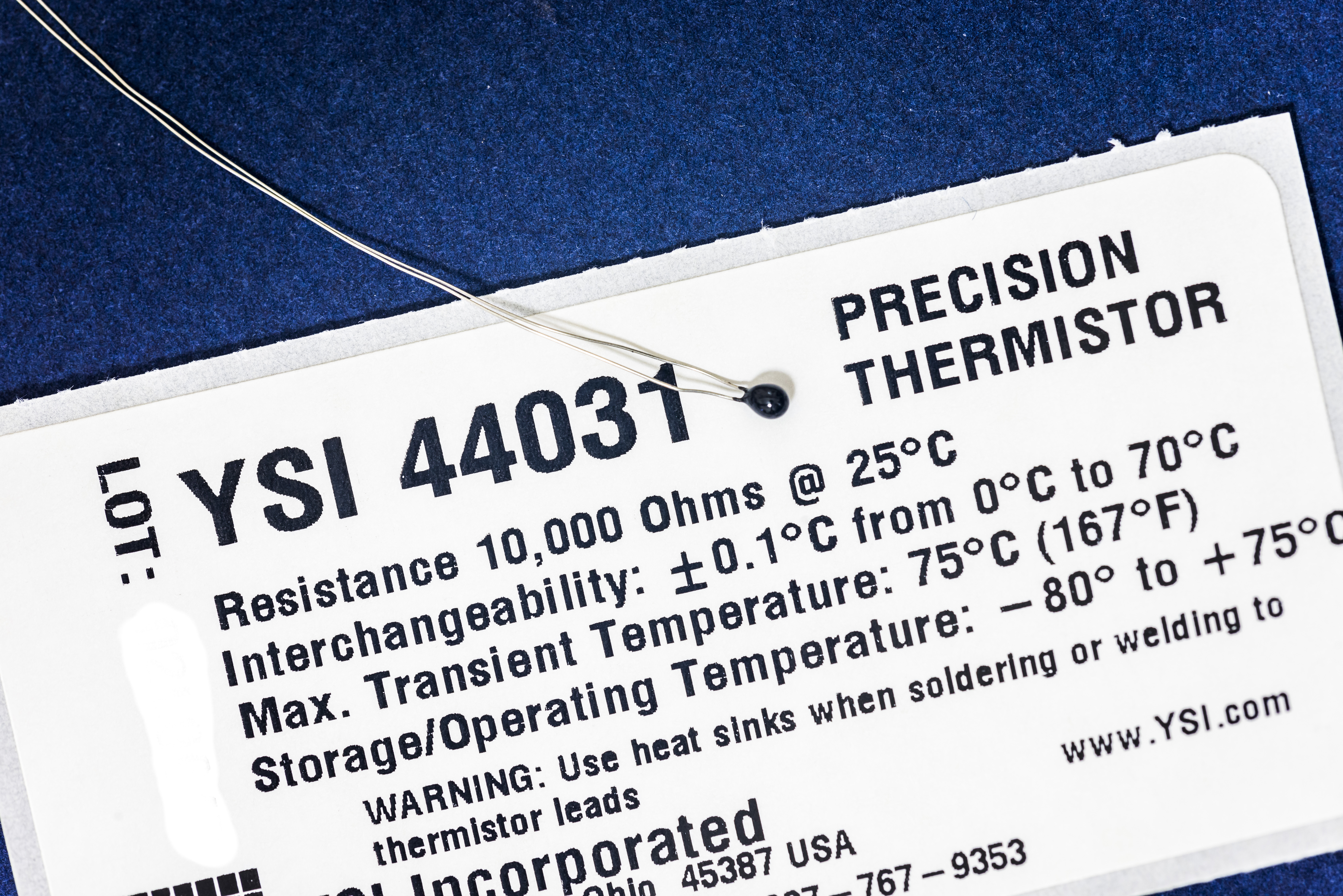
Image 23: Precision thermistor YSI 44031
Precision 10KΩ (25°C) thermistor from YSI, Model 44031 is used as thermal sensor feedback, connected to Keithley SMU by 4-wire cable. Today these termistors are manufactured and sold by Omega, another big and well-known thermal solutions manufacturer.
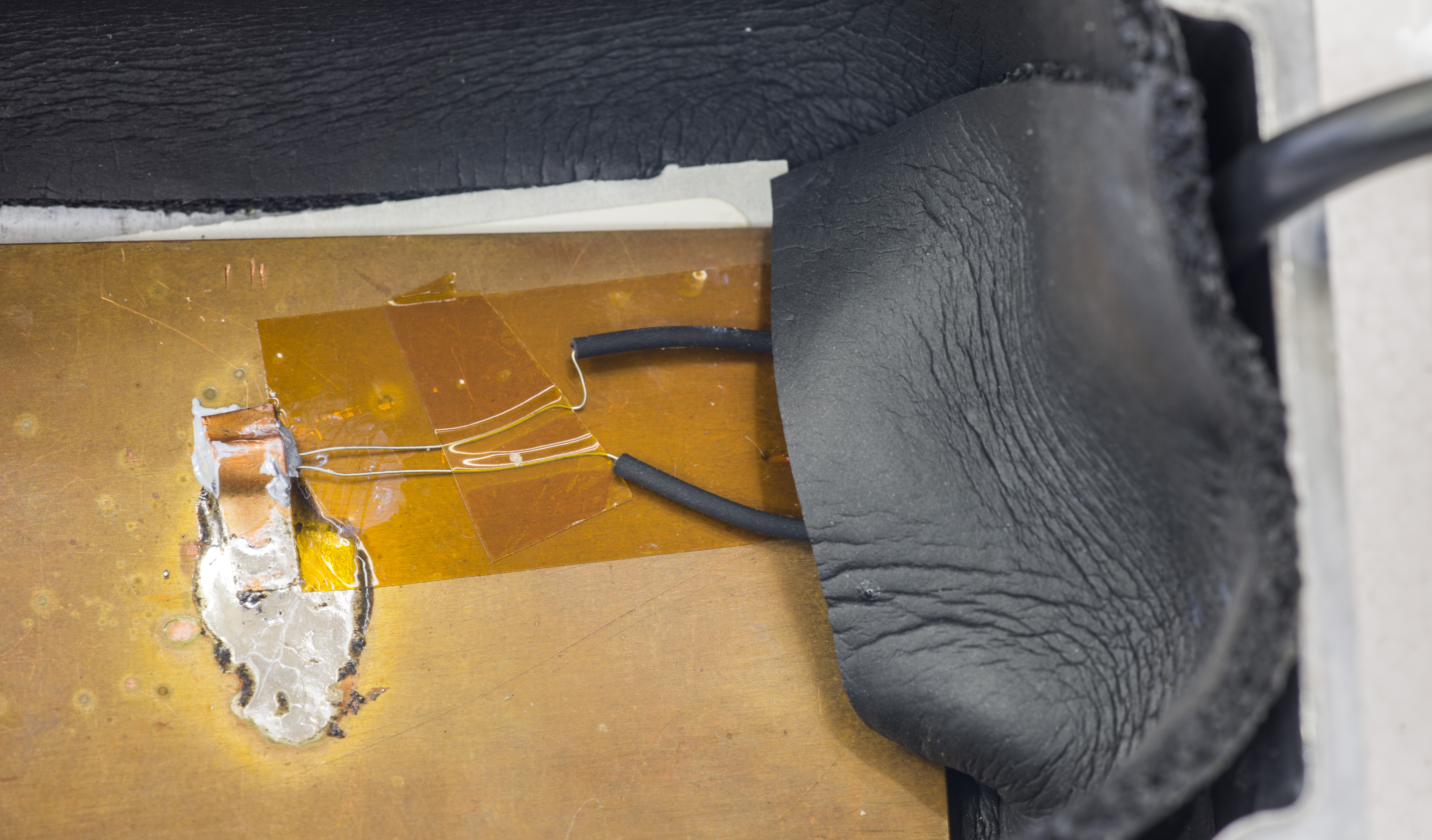
Image 24: Thermistor mounted to a plate
Few mm thick copper plate added on the bottom of the chamber as thermal damper, with thermistor mounted in center. Thermal grease was used to enhance surface contact and provide good thermal coupling of sensor with metal slug to minimize self-heating and readings noise. Make sure you don’t subject sensitive thermistor to temperatures over +75°C and use heatsinking during leads soldering.
Now it’s ready to accept our module :)
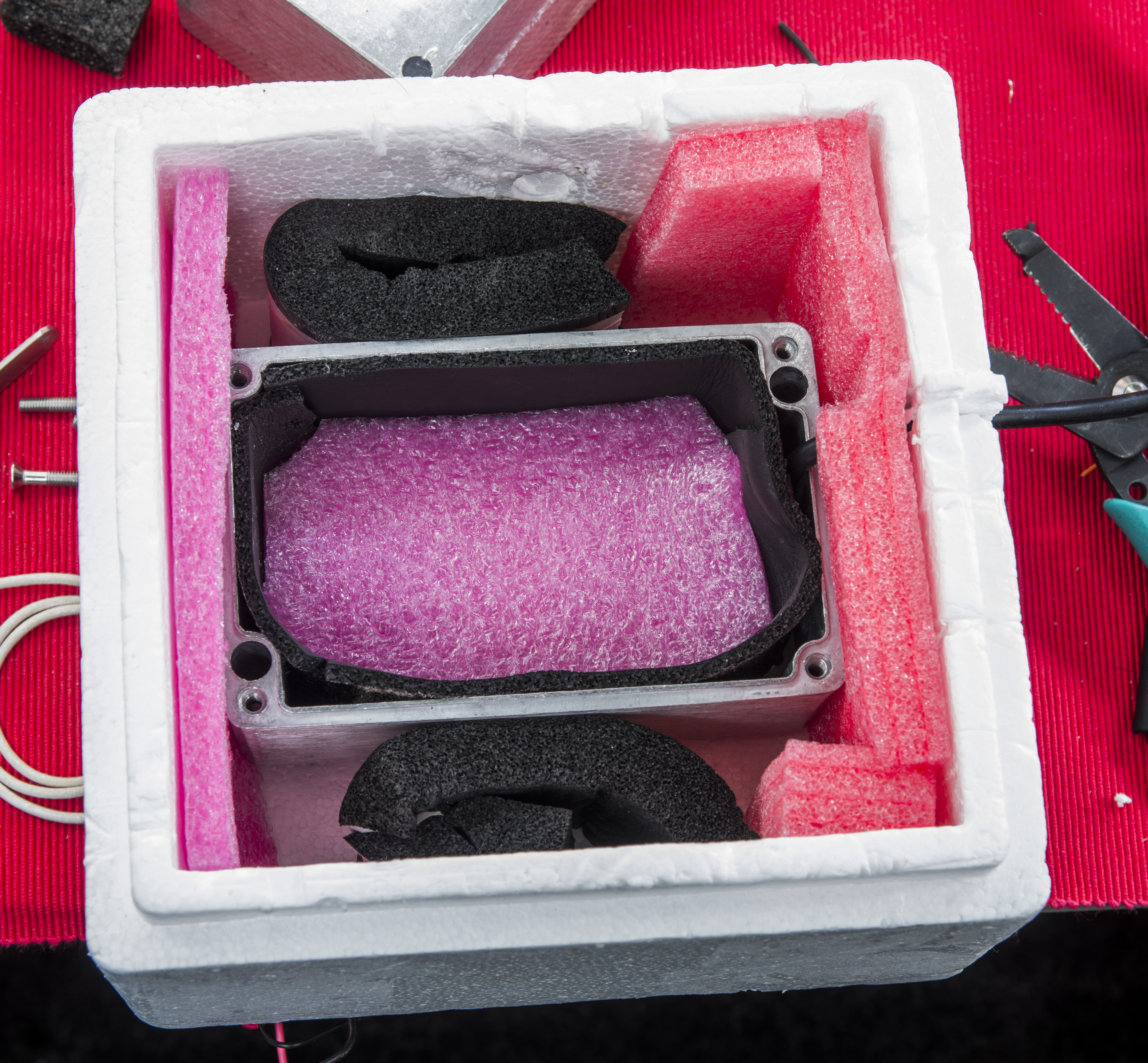
Image 25: Box ready for DUT modules
As TEC is semiconductor device, it require stable bidirectional current supply. Depends on polarity, TEC module will transfer heat flow from one side to another, and thus will be able to control temperature directly. Our goal is stable temperature of test chamber, independent from ambient variations, so temperature feedback loop will be used to set TEC power and direction.
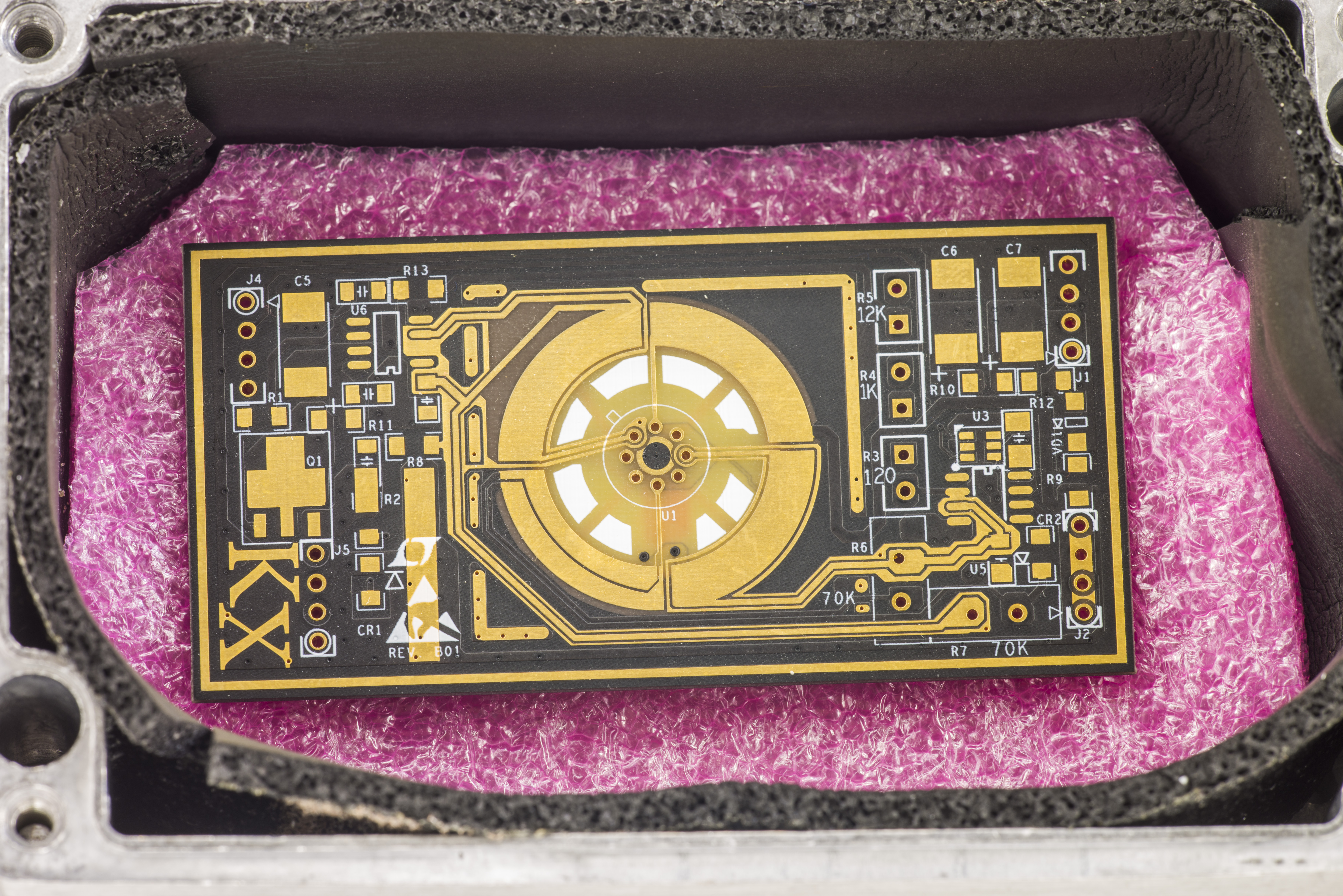

Image 26-27: Examples with KX VREF module
Keithley 2510 TEC SourceMeter which I had repaired and calibrated few years ago is a perfect controller for our task here, providing up to 10.5V 5A. Our TEC module is specced just above that at 12V 6A, to be on a safe side. Overload on TEC junctions will cause failure, so limits need to be set correctly for such systems.


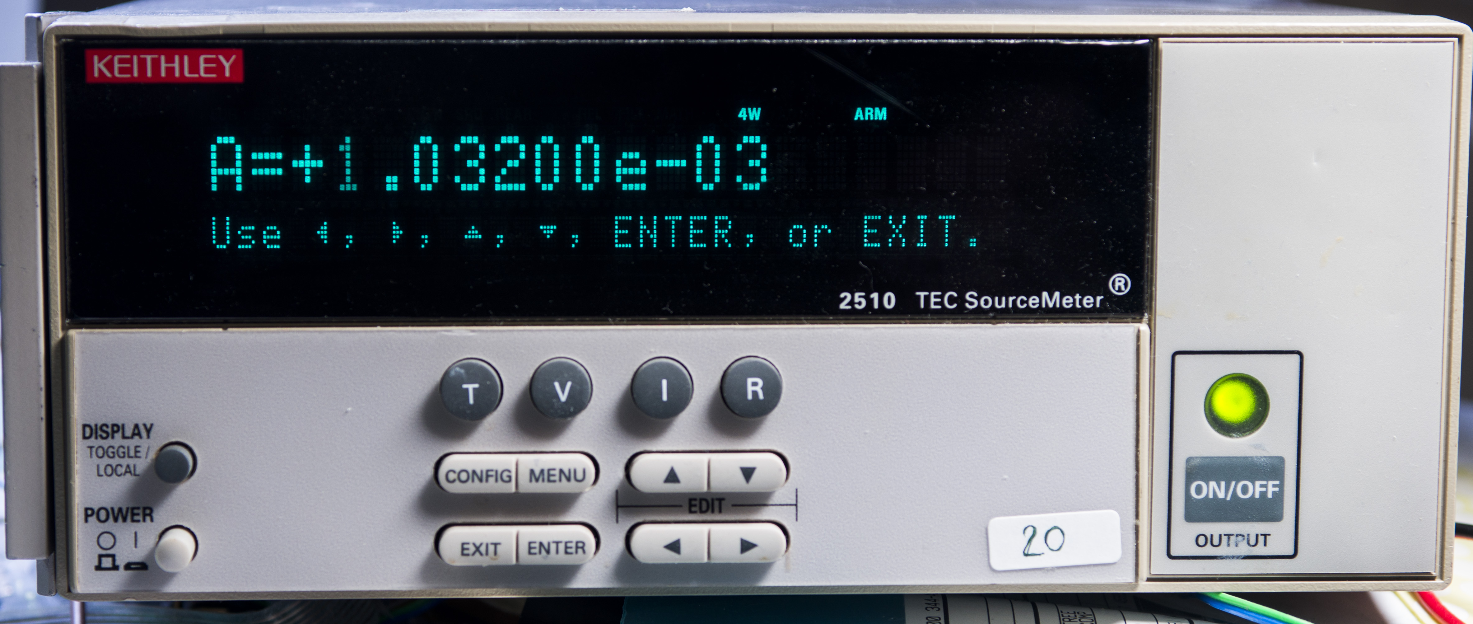

Image 28-31: Keithley 2510 configuration
Our thermistor specified accuracy is ±0.1 °C and it does not require calibration to this task. We need only relative measurements anyway, and absolute temperature accuracy is less important here.
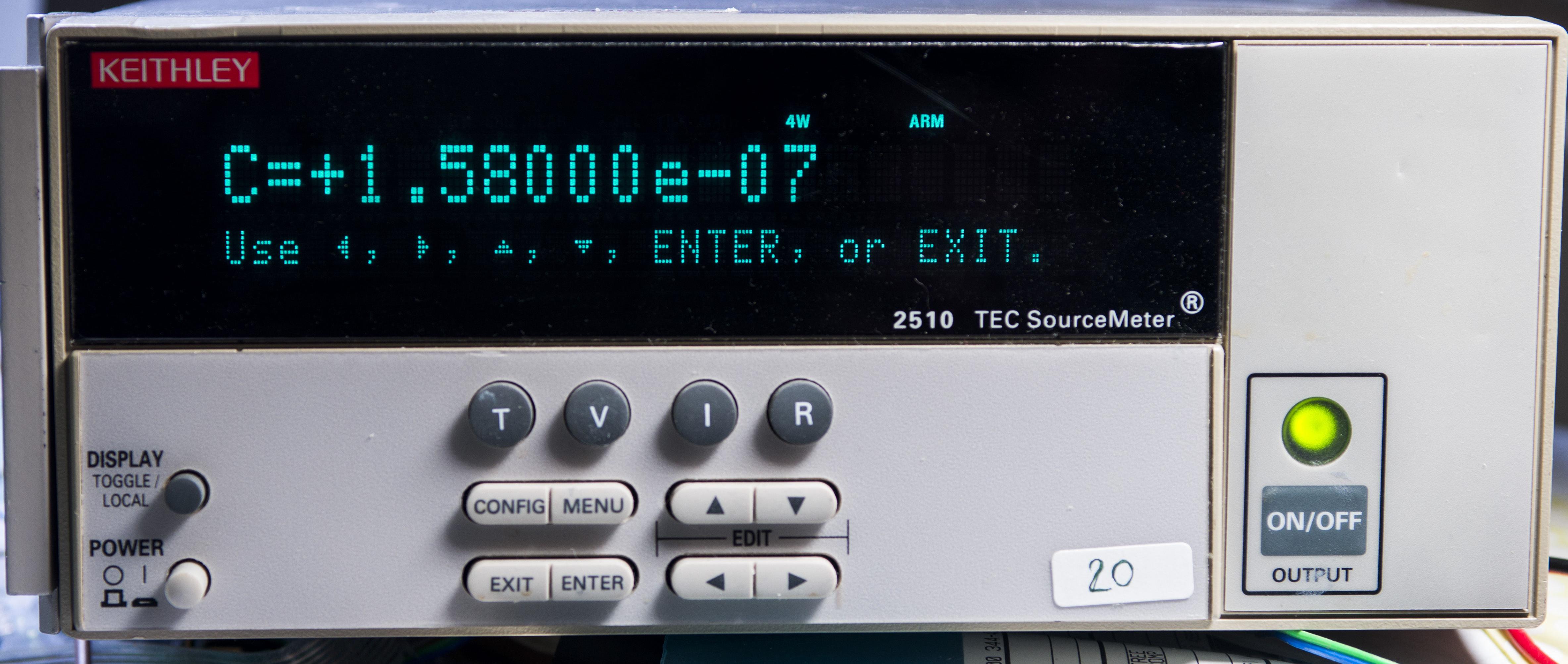
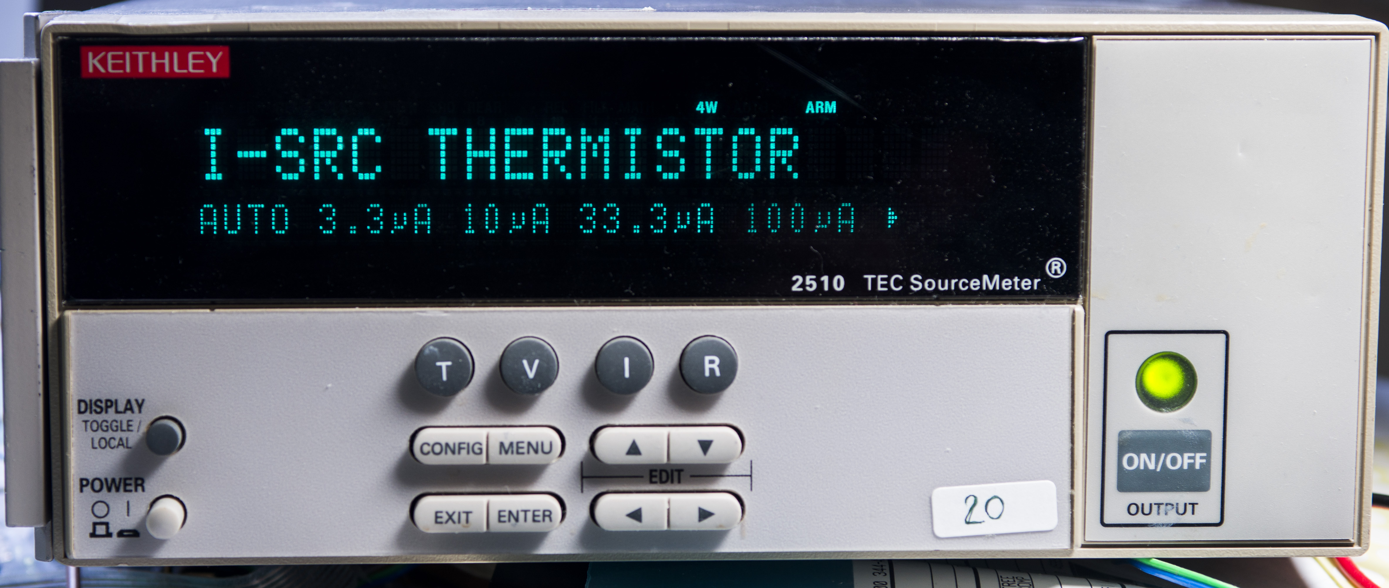
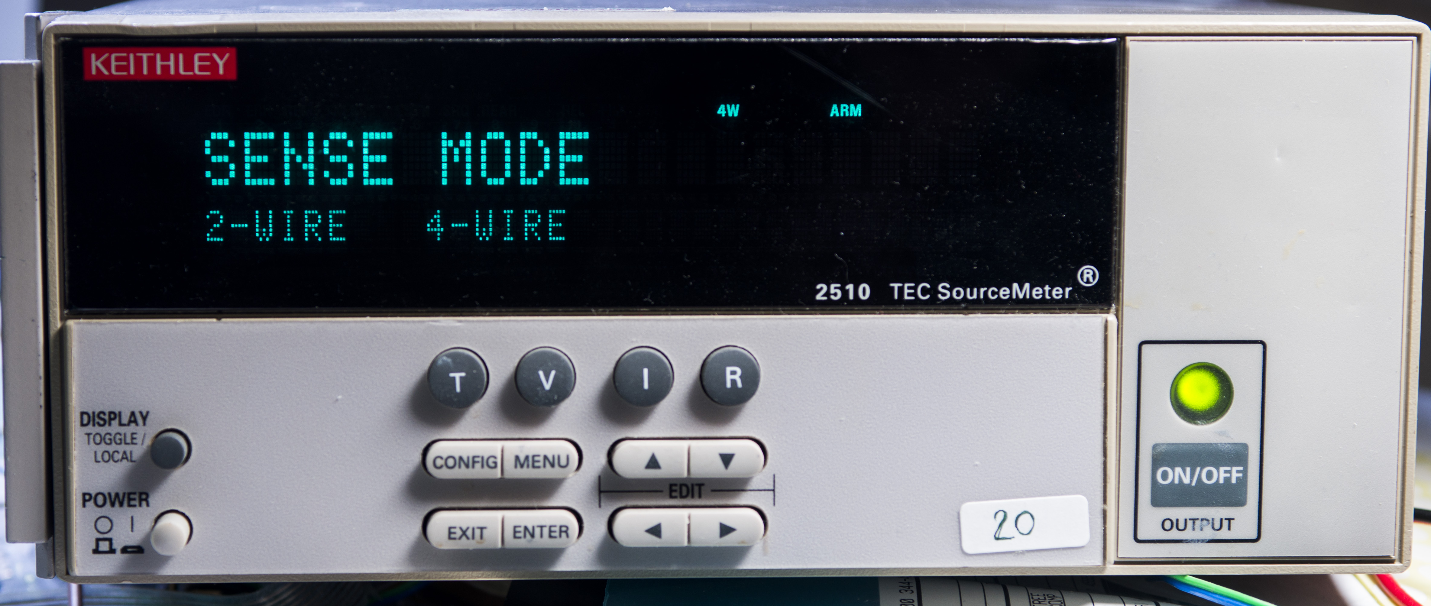
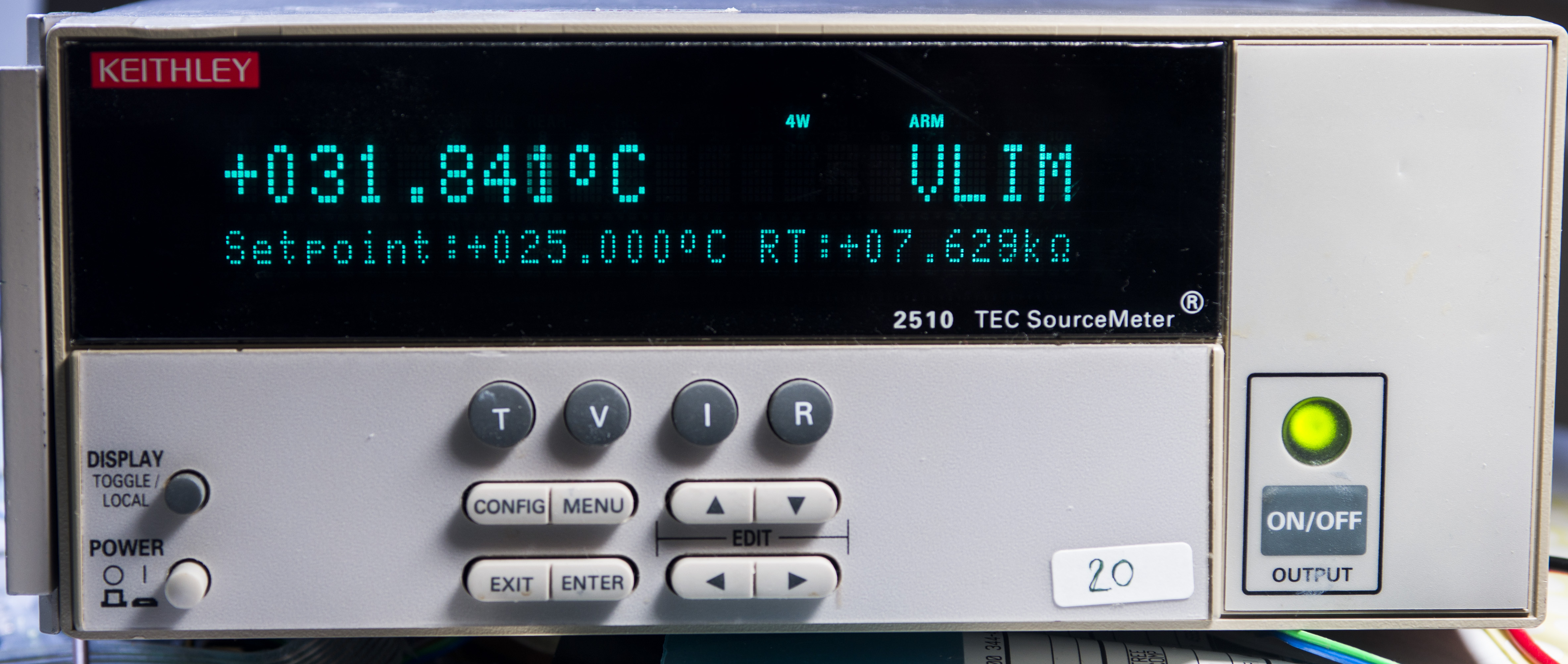
Image 32-35: Keithley 2510 configuration
Here is Python-code used to configure Keithley 2510 for this chamber via linux-gpib.
def init_inst(self):
        # Setup SCPI DMM
        self.inst.write("*rst") #reset TEC controller
        self.inst.write("*CLR")
        #Set temperature transducer to thermistor and 4-wire sense mode
        self.inst.write(":sens:temp:tran ther")       #Select thermistor sensor
        self.inst.write(":sens:temp:ther:a 1.032e-3") #Set A coefficient
        self.inst.write(":sens:temp:ther:b 2.387e-4") #Set B coefficient
        self.inst.write(":sens:temp:ther:c 1.580e-7") #Set C coefficient
        self.inst.write(":sens:temp:ther:rang 10000") #10 kOhm thermistor range
        self.inst.write(":sens:temp:curr 1e-4")       #100 uA thermistor current
        self.inst.write(":syst:rsen on")              #4-wire mode enabled
        self.inst.write(":sour:volt:prot 10.0")     #Max voltage limit
        self.inst.write(":sens:curr:prot 3.0")      #Max current limit
        self.inst.write(":sour:temp:prot:high 65")  #65C max temp
        self.inst.write(":sour:temp:prot:low 10")   #10C min temp
        self.inst.write(":sour:temp:lcon 150")      #150 P
        self.inst.write(":sour:temp:lcon:int 0.05") #0.05 I
        self.inst.write(":sour:temp:lcon:der 1.60") #1.6 D
        self.inst.write(":sour:temp:prot:state ON") #enable temp #protection (default)
A,B,C coefficients are taken from thermistor datasheet.
Temperature for chamber is ramped from 20.0 °C to 55 °C in 1°C/hour speed step increment. This allow enough time to have at least 30 minutes of stable temperature sample window.
   def adj_tmp(self,tmp):
        string = float(tmp)
        print ("Setting %2.1f" % string)
        self.inst.write(":sour:temp %2.1f" % string)
        self.inst.write(":OUTP ON")
Higher level code with temperature set point calculation:
   if (tec_rtd >= 55.0):
        meter2510.off_temp(tec_rtd)
        quit()

    if ((cnt % 600) == 0):
        xtemp = 20.0 + (float(cnt) / 600)
        print ("Set TEC Temp = %2.1f" % xtemp)
        meter2510.adj_tmp(xtemp)
Variable cnt is simple main loop sample counter, xtemp is setting temperature from Keithley 2510, while tec_rtd variable is measured sensor value. Once reading hits +55.0 °C TEC SMU will be put into standby and program will be terminated, completing the test.
Full Python-app listing for datalogger
Page JavaScript code using D3.js for datalog graph
Used instruments:
- HP 3458A – 8½-digit metrology grade DMM, GPIB 3
- Keithley Model 2002 – 8½-digit DMM, GPIB 11
- Keithley Model 2510 – TEC SMU, GPIB 25
- Keithley Model 2400 – 22W 200V/1A SMU
Thermal coefficient result
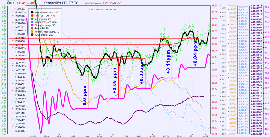
Image 36: Results from Run 6. Click for live data for tempco
Delta deviation in ppm per each °C is shown on graph.
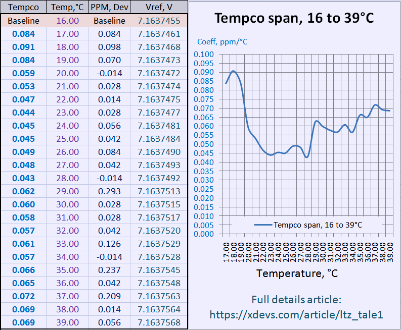
Also for easier grasp, here’s summary data on chamber temperature span from +16 °C to +31 °C (temperature stability &plumn;0.005 °C). Perhaps bit easier on table below with calculated temperature coefficient and output deviation delta in ppm units. Voltage reading at +16.000 °C was taken as a baseline.
As we can see, temperature coefficient stays very close to ±0.05 ppm/K specification. Also one has to remember than this test is essentially a comparison of internal HP 3458A LTZ1000-reference versus external. So accuracy of such measurements is already ±0.1 ppm at best. To perform better measurement, one would need measurement equipment more stable than old aged HP 3458A, which leaves very few options, like very expensive JJA systems or characterized bank of Fluke 732A/732B DC standards and low-noise null-meter.
RAW samples data in DSV-format is available as well, if you reader desire to conduct own analysis.
DSV-data log with temperature chamber test
Summary
Let’s make a final count for funds spent.
| Description of the part/item | Cost, in USD |
|---|---|
| LTZ1000ACH chip | 55$ |
| LTZ1000CH chip | 45$ |
| KX PCBA | — |
| ADA4522-1 | 5$ |
| Film capacitors | 5$ |
| Metal foil resistors from eBay | 120$ |
| Shipping | 40$ |
| Total cost | 225$ |
Total amount of time for this project ~25 hours, including ~300 hours of datalog time by HP 3458A.
So PCBA build which would take normally just few hours for normal projects took nearly a week of time (2-4 hours each day) and required expensive (MSRP >10k $USD) and verified instrumentation to ensure required performance level.
Hope these efforts would help to better understand hidden icebergs and dangers big enough to sink a project in high-precision field, even for something as simple as direct voltage reference module.
UPDATE: Calibration offer for members with featured KX LTZ1000A PCB
After discussion on EEVBlog forum, member mimmus78 decided to jump in and order my Gerber files for LTZ1000A module, as I had already sent all extra ones long time ago.
He got PCB fab to manufacture 20pcs and decided to send all but 3 boards to other metrology enthusiast at the cost.


Image 37-38: KX LTZ1000 PCBs received by mimmus78
And there is some healthy number of people willing to try their own build using these boards:
| EEVBlog member | Boards qty |
|---|---|
| VK5RC | 3 pcs |
| t2kv | 2 pcs |
| klaus11 | 2 pcs |
| HighVoltage | 2 pcs |
| Mimmus78 | 3 pcs |
| pelule | 3 pcs |
| Nuno_pt | 3 pcs |
| msliva | 3 pcs |
| SvanGool | 2 pcs |
| fanOfeeDIY | 2 pcs |
I did not really expect such following of this little project, so decided to provide bit of support in return, to encourage such project involvement.
Support boils down to free (almost, you still cover shipping) calibration service of any xDevs.com KX voltage reference module using these LTZ1000 PCBs.
To make things simple, here are the “rules”.
STEP 1. Build your KX-module, publish short worklog in this thread (few photos of assembled PCBA, photo of it running with DMM hooked up showing 7V)
STEP 2. Leave it running for 200 hours, so initial drifts get stabilized. Module should be enclosed in some box without vents.
STEP 3. Measure it again, record the temperature and voltage and put a label with values on the box
STEP 4. Ship the box to me (Taiwan). You pay shipping.
STEP 5. I’ll power your box with +15V for 48 hours to have everything stabilize
STEP 6. Test 7V output voltage in temperature span +20….+30C, record the graph
STEP 7. Unit will be shipped back via EMS Express (~30-40$USD, 4-7 days to USA, bit more to EU). You pay shipping.
All steps are mandatory, to make sure that reference is good and stable, otherwise it would be no much point in ppm-level calibration, if initial aging drifts are not removed first.
This is standing offer, without schedule or specific date deadlines, unless my homelab changes or other force majeure events occur.
Even though I don’t have official calibration performed on my equipment, thanks to volt-nut community and multiple cross-checks I’m confident that my DCV accuracy is around ±2 ppm.
And to make this even better, few other EEVBlog members also backed up this initiative to provide same calibration offer in their regions.
| Calibration by | Accuracy / Standard | Region/Country | Contact for participants |
|---|---|---|---|
| xDevs.com | <±2ppm / 3458A-mod + 2*K2002 | Asia/Taiwan | EEVBlog forum PM |
| plesa | <±4ppm / 3458A-002 | Europe/Sweden | EEVBlog forum PM |
| Alex Nikitin | <±4ppm / 3458A-002 | Europe/UK | EEVBlog forum PM |
Thumbs up for the members! I’d be happy to publish these folks builds test results and photos of their home setup, perhaps in next upcoming “fairy-tale” article!
Modified: Dec. 28, 2016, 2:21 p.m.