Contents
- Intro
- Disclaimer
- Manuals
- Exterior
- Teardown and diagnostics
- Firmware
- Repair
- Performance testing
- Calibration
- Remote control
- Restoration summary
Intro
Datron (later Wavetek) Model 4920 is AC Voltage measurement standard, which is essentially a high precision voltmeter, but designed with sole goal to perform accurate AC voltage measurements. After Datron/Wavetek instrumentation division acquisition by Fluke in early 2000’s this AVMS was discontinued and replaced by Fluke’s 5790A AC Measurement Standard.
Let’s take a look on key specifications of high-performance AC standards and compare them to one of the best DVMs – HPAK 3458A.
| Wavetek/Datron 4920M | Fluke 5790A | Fluke 5790B | HPAK 3458A | |
|---|---|---|---|---|
| Ranges, VAC | 3m to 1000 in 3,10,30 sequence | 2.2m, 7m, 22m, 70m, 220m, 700m, 2.2, 7, 22, 70, 220, 700, 1000 | 2.2m, 7m, 22m, 70m, 220m, 700m, 2.2, 7, 22, 70, 220, 700, 1000 | 10m, 100m, 1, 10, 750(1000) |
| Wideband ranges,VAC | 3V single | 700m, 7 | – | |
| Wideband frequency | 50 MHz | 30 MHz | – | |
| Wideband impedance | 50 Ω ±0.5% | 50 Ω ±0.5% | – | |
| Inputs type, main | Type N | Type N + 5-way Binding posts, shunt input | Type-N + 5-way Binding posts, shunt input | 5-way binding posts |
| Inputs type, WB | Type N | Type N | Type-N | N/A |
| Resolution | 100nV, 7½ digits | 100nV, 6½ digits | 100nV, 6½ digits | 1µV, 6½ digits |
| Operating range | 30% to 110% of the range | |||
| Best accuracy | 10ppm (90d) 10-30kHz, 300mV-30V | 22ppm (90d), 40Hz-20kHz, 2.2V-7V | ||
| Interface | GPIB IEEE488 | RS232C, GPIB IEEE488 | ||
| Dimensions, weight | 88 × 427 × 487mm, 11.8kg | 178 × 432 × 630mm, 24.5kg | ||
| MSRP | $10495 USD | $34999 USD | $xxxxx USD | $9k USD |
| Year | 19xx | 1990 | August 2015 | 1986 |
Table 1. Comparison table for AC voltmeters
There are two known modifications of this AVMS, Model 4920 and Model 4920M. Later one is military version. Differences between the two are listed in Table 2.
| Feature | Regular 4920 | Military 4920M |
|---|---|---|
| Input for ACV | Banana post | Type N |
| Input for WBV | LEMO option input | Type N |
| mV option | Option 10 | Not available |
| WB option | Option 50 or Datron 4922 | Integrated, standard |
| Other difference | Menu system with mV ranges | Removed mV ranges items |
Table 2. Comparison of 4920 and 4920M
Other than that high accuracy main ACV input is about the same for both models and overall operation is same.
Possible add-on options for Wavetek 4920:
| Description | MSRP | |
|---|---|---|
| Option 10 | 3mV to 100mV ranges | $1570 USD |
| Option 50 | Wideband module to extend input frequency to 50MHz | $2995 USD |
| Option 80 | 115V 60Hz line operation | Included |
| Option 81 | 115V 50Hz line operation | Included |
| Option 90 | Rack mounting kit | $165 USD |
| Option 95 | Rack mounting slides | $385 USD |
Table 3. Options and accessory table
There was also standalone wideband module option for 4920, such as Datron/Wavetek 4922 which covers frequency range 10 Hz to 50 MHz. This external module plugs into option LEMO-type port on regular 4920. 4920M has it integrated as standard, replacing mV-module.
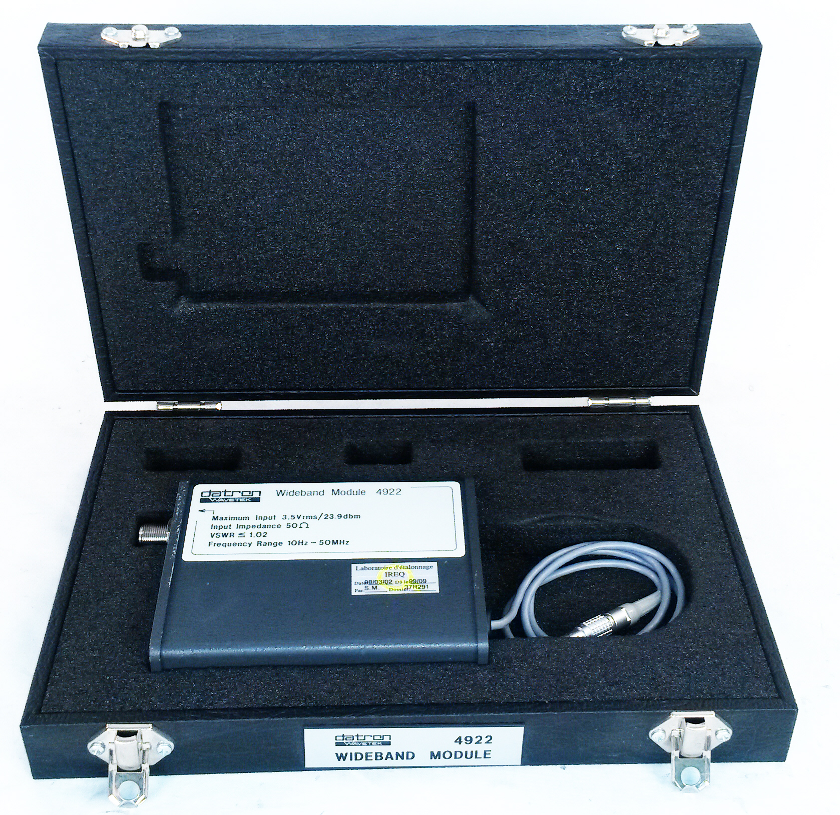
Image 2: Datron 4922, photo courtesy AccuSource Electronics .
And yes, you guessed it, xDevs.com labs got one of these Wavetek 4920M units. Will it be another rabbit hole like HP 3458A 220+ hours repair project? Very well might be, let’s find out! Unit received in “unknown” conditions, only tested for power on.
Disclaimer
Redistribution and use of this article or any images or files referenced in it, in source and binary forms, with or without modification, are permitted provided that the following conditions are met:
- Redistributions of article must retain the above copyright notice, this list of conditions, link to this page (/fix/d4920m/) and the following disclaimer.
- Redistributions of files in binary form must reproduce the above copyright notice, this list of conditions, link to this page (/fix/d4920m/), and the following disclaimer in the documentation and/or other materials provided with the distribution, for example Readme file.
All information posted here is hosted just for education purposes and provided AS IS. In no event shall the author, xDevs.com site, or any other 3rd party, including Fluke/Wavetek be liable for any special, direct, indirect, or consequential damages or any damages whatsoever resulting from loss of use, data or profits, whether in an action of contract, negligence or other tortuous action, arising out of or in connection with the use or performance of information published here.
If you willing to contribute or add your experience regarding Fluke/Wavetek/Datron instruments repairs or provide extra information, you can do so following these simple instructions
Manuals
With help of our contributors Todd and pelule electronic versions of manuals are available:
Datron/Wavetek 4920M AVMS User’s Manual
And gold resource for repair and servicing:
Datron/Wavetek 4920M AVMS Service Manual, Volume 1
Datron/Wavetek 4920M AVMS Service Manual, Volume 2
Datron Wavetek 4920 special calibration sheet, Ver 4.1
Datron Wavetek 4920/4920M hardware compatability notes
Datron Wavetek 4920/4920M Calibration verification methods
Datron Wavetek 4920/4920M Digital Assembly test procedure 15-05-1991
Datron Wavetek 4920/4920M difference to 1281 digital hardware training
Datron Wavetek 4920/4920M ADC test procedure
Credits to Ken Eckert for these rare 4920/4920M manuals!
Pay attention, that unlike Keithley 2001 and 2001M these units with and without “M” are rather different in both function and hardware.
Also here’s regular 4920 user’s manual:
Datron/Wavetek 4920 AVMS User’s Manual
Datron/Wavetek 4920 Design, Application and Performance
Datron/Wavetek 4920 Calibration
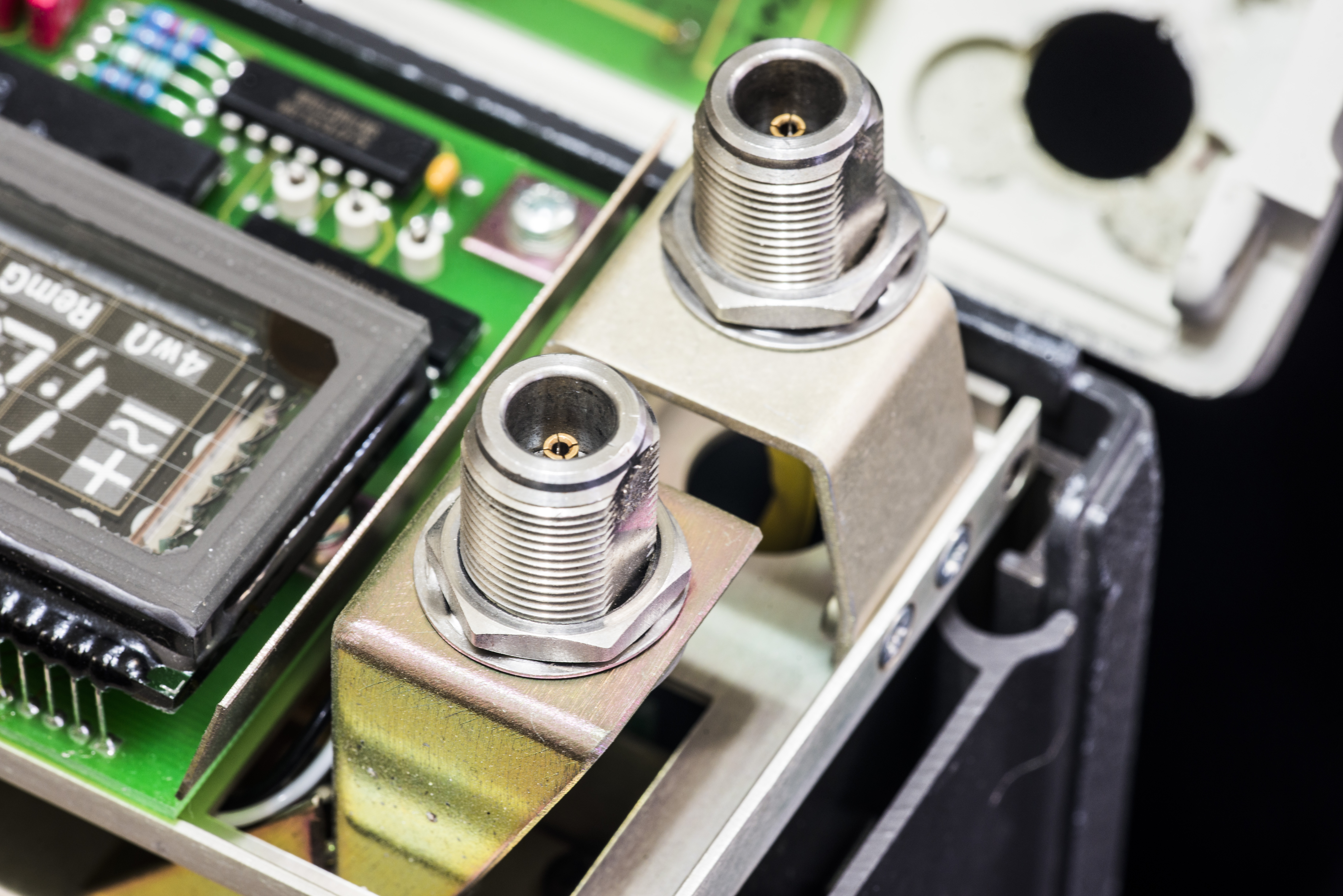
Exterior and interface
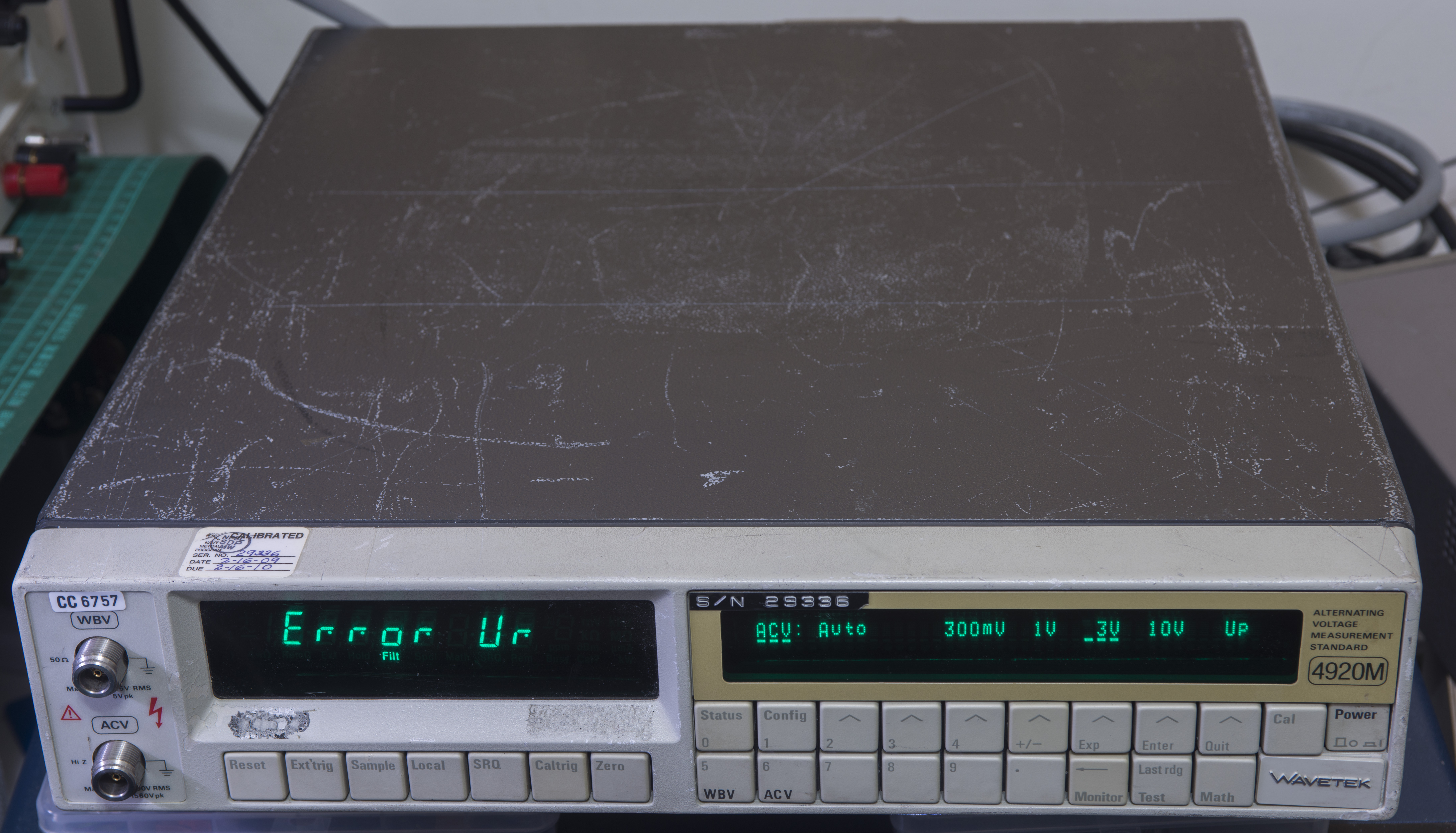
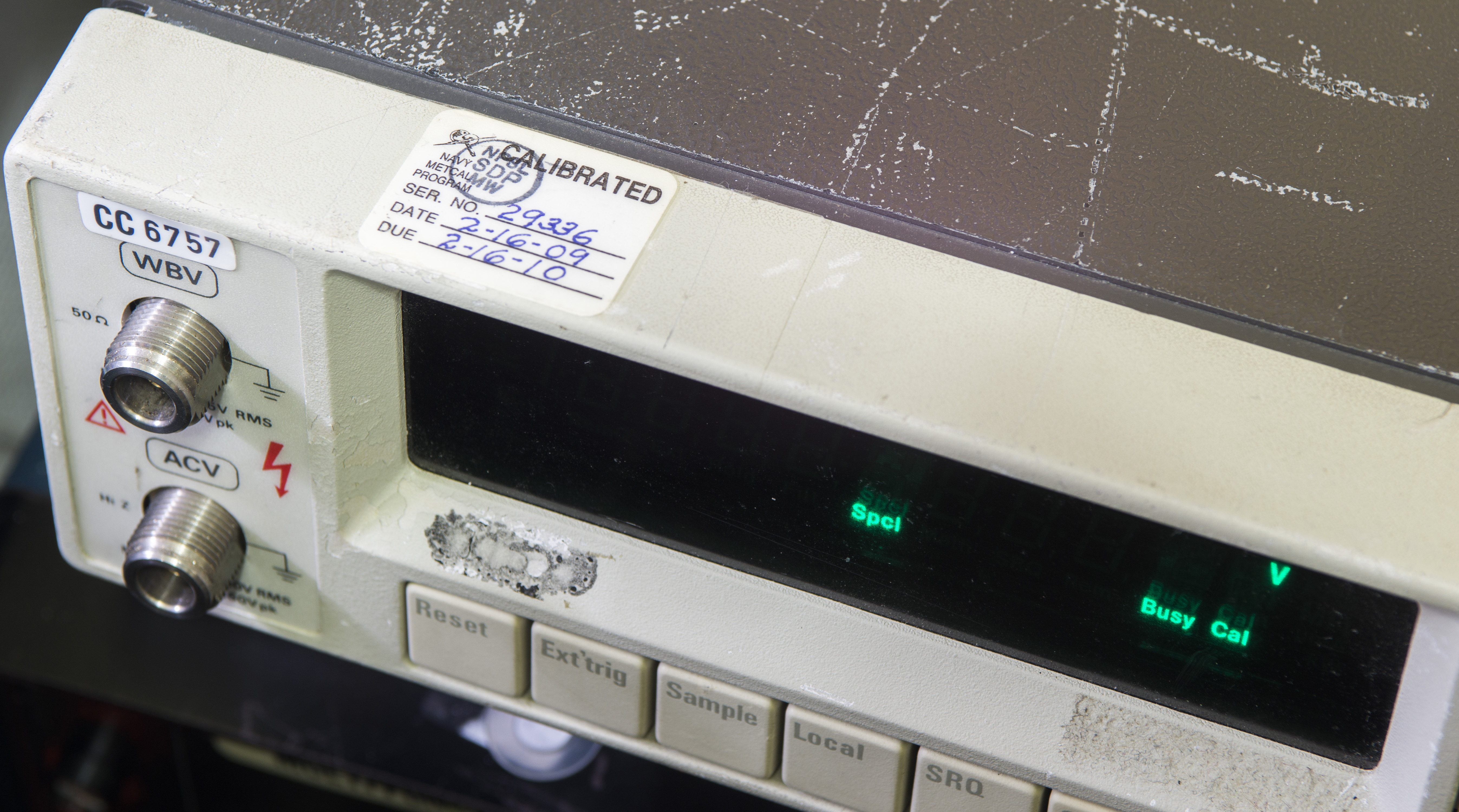
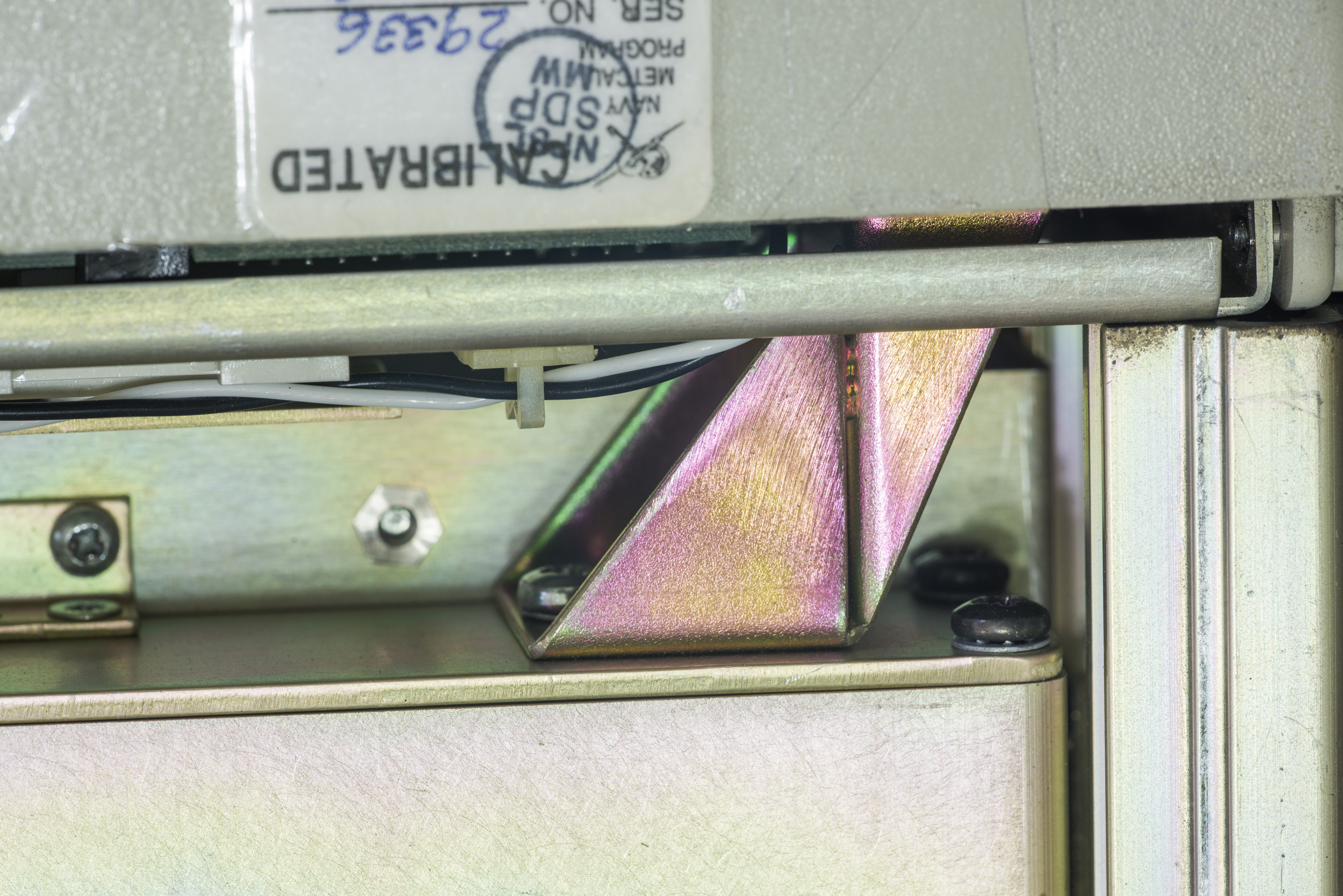
Unit is pretty banged up externally, with many scratches. Well, given sticker labels on rear panel, unit was used in US Navy calibration standard lab. So this box probably had intensive and eventful naval life. Maybe there are some ocean crabs hiding inside?
The Error Ur is an under-range error; you have to apply an input above minimum level (about 10%) of the range before it AVMS start to sample and display a reading. For better understanding table with acceptable input voltages for each range is presented. For specified accuracy input signal must be at least 30% of the selected range.
| Range | Input signal, min | Input signal, max |
|---|---|---|
| 300 mV | 90 mV | 330 mV |
| 1 V | 300 mV | 1.1 V |
| 3 V | 0.9 V | 3.3 V |
| 10 V | 3 V | 11 V |
| 30 V | 9 V | 33 V |
| 100 V | 30 V | 110 V |
| 300 V | 90 V | 330 V |
| 1000 V | 300 V | 1100 V |
| 1 V WB | 100 mV | 1.15 V |
| 3 V WB | 0.99 V | 3.5 V |
Table 4. Input levels for rated performance specifications
Also manual states warm-up time for the 4920M to reach specification only 30 minutes. Its bit unusually short time for metrology-grade instrument, as usually such warm-up time is 4-8 hours, sometimes even a day.
Serial number on unit does match stored number in NVRAM.


Teardown and diagnostics
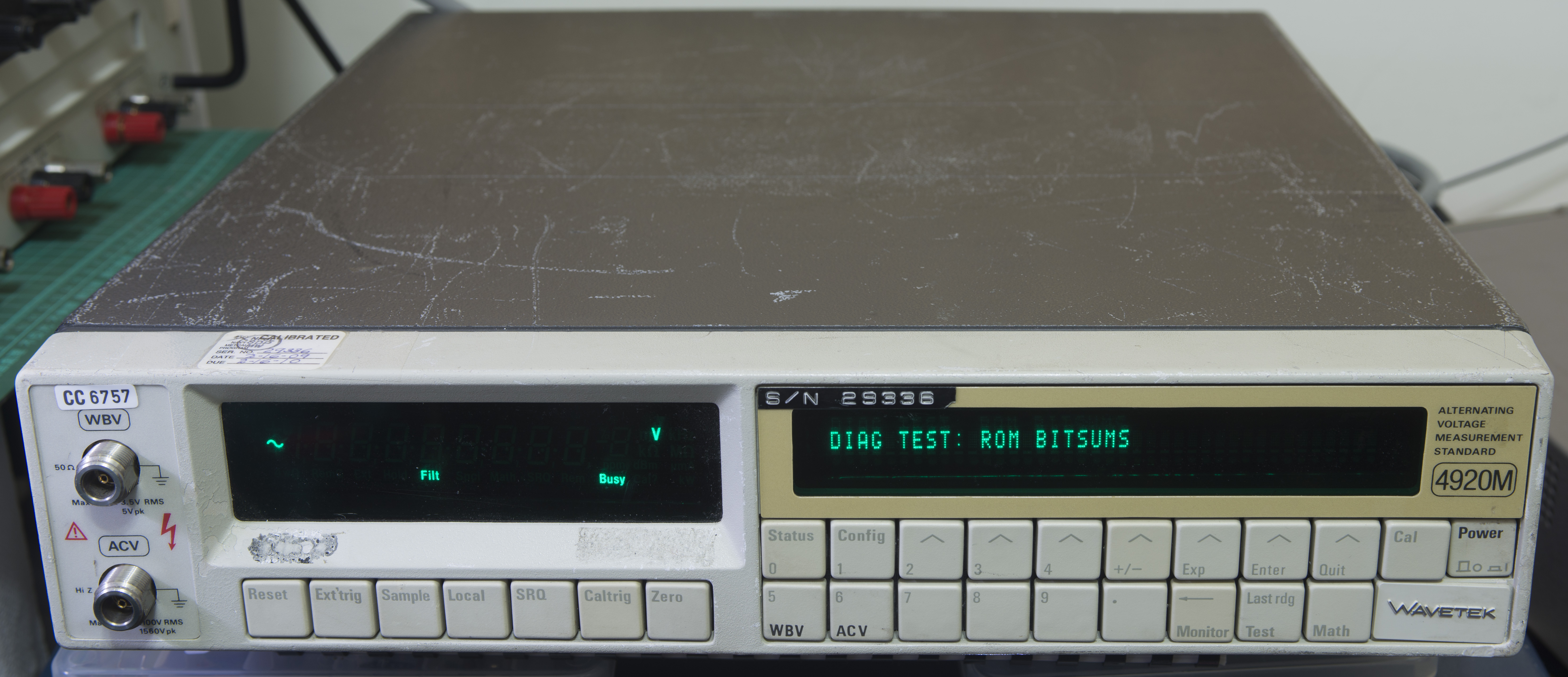
Before we remove those covers, let’s run diagnostic procedures per service manual and see what initial conditions are. Unit was sold as “Used” with photos showing power on condition, so it should be okay to have it powered. No smoke and bad PSU issues expected.

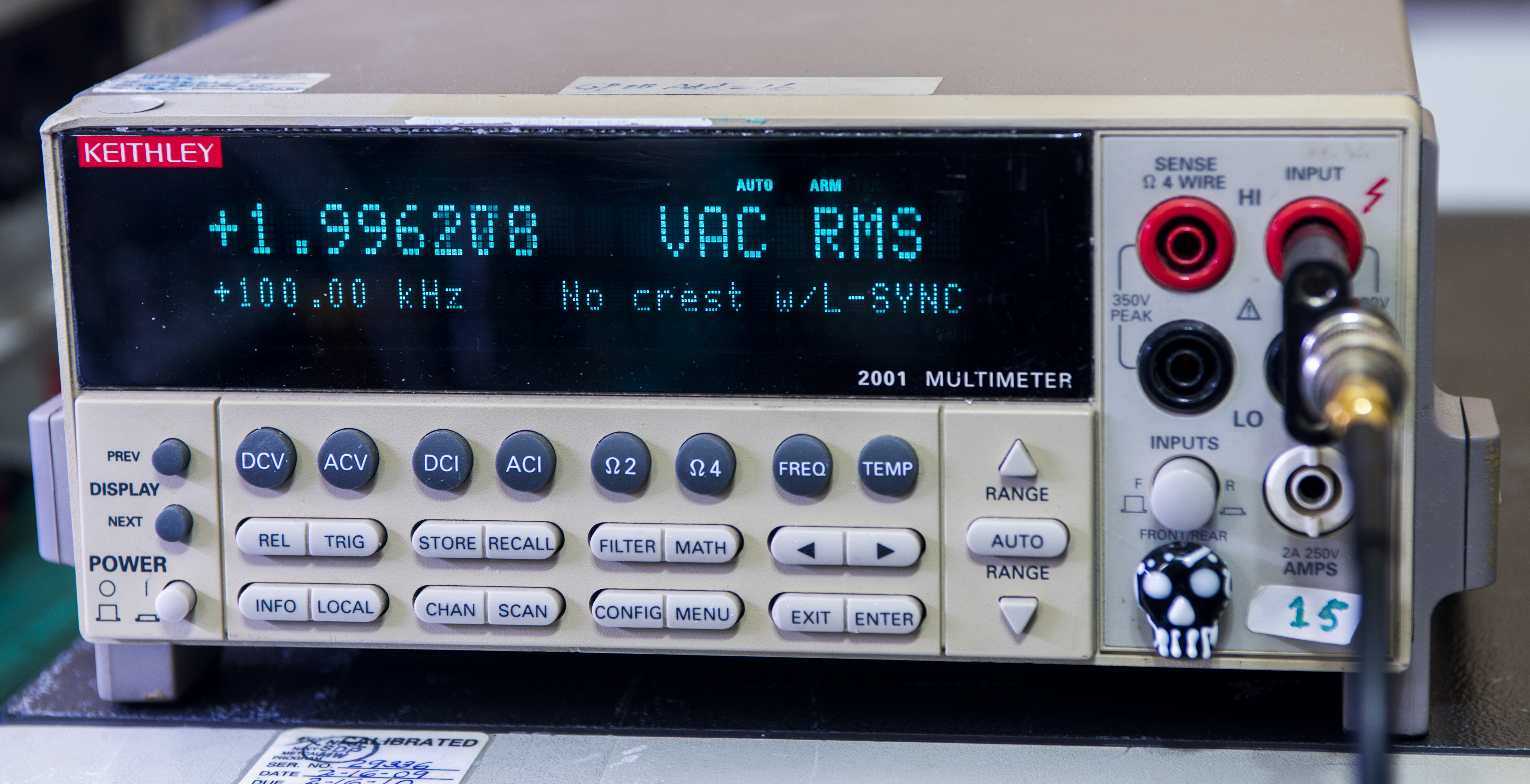
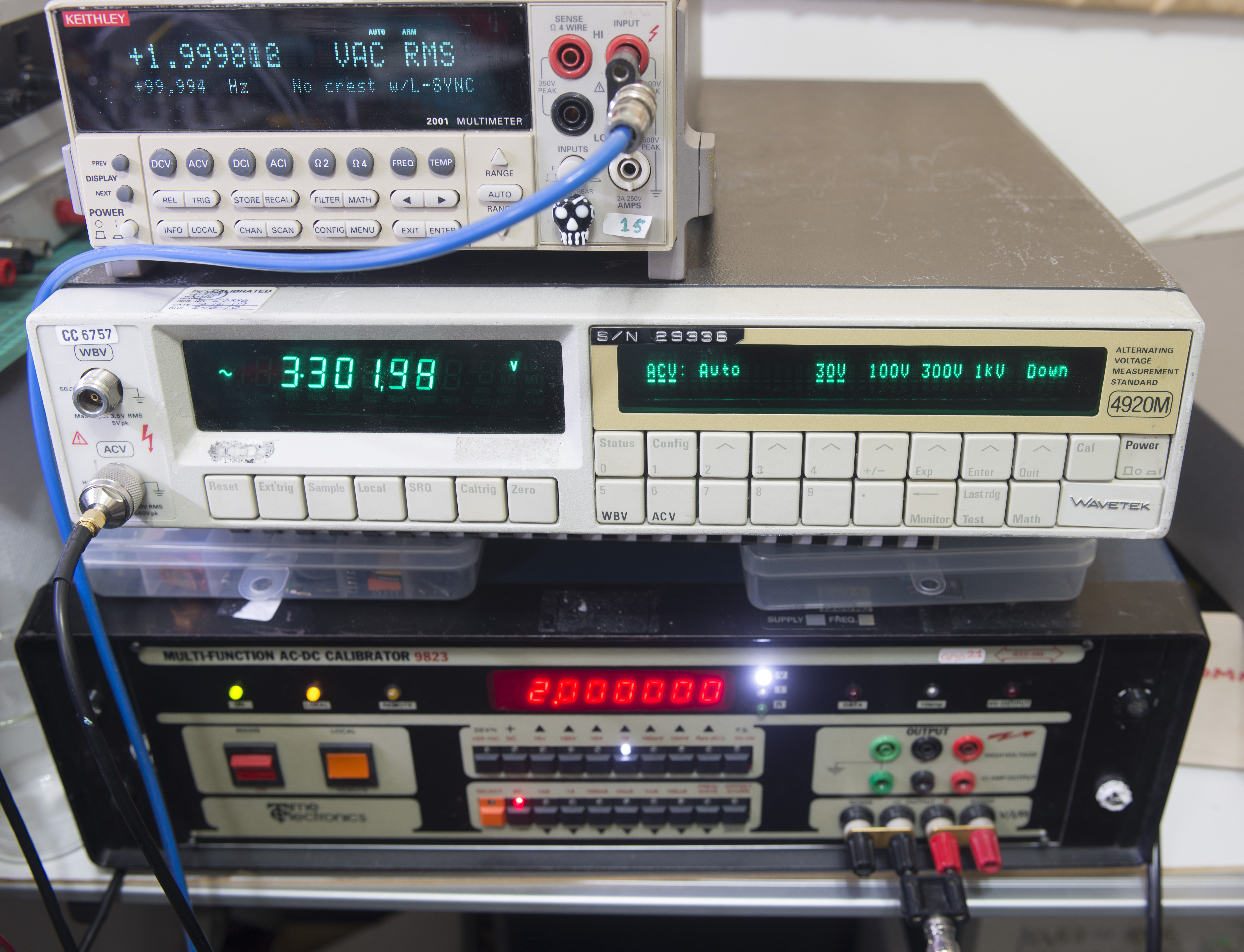
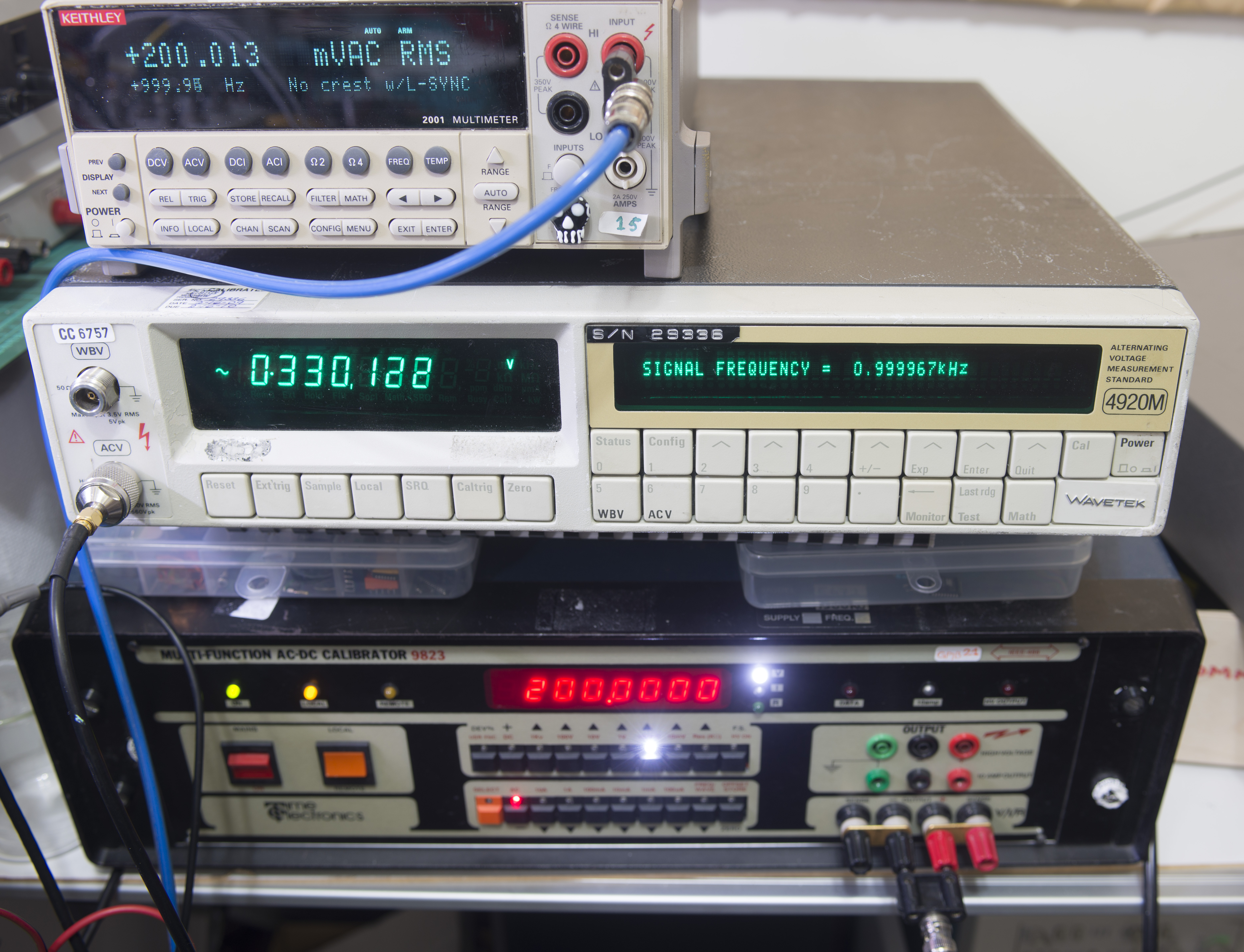
Check with Keithley 2001, calibrated by Tektronix Taiwan in February 2014.
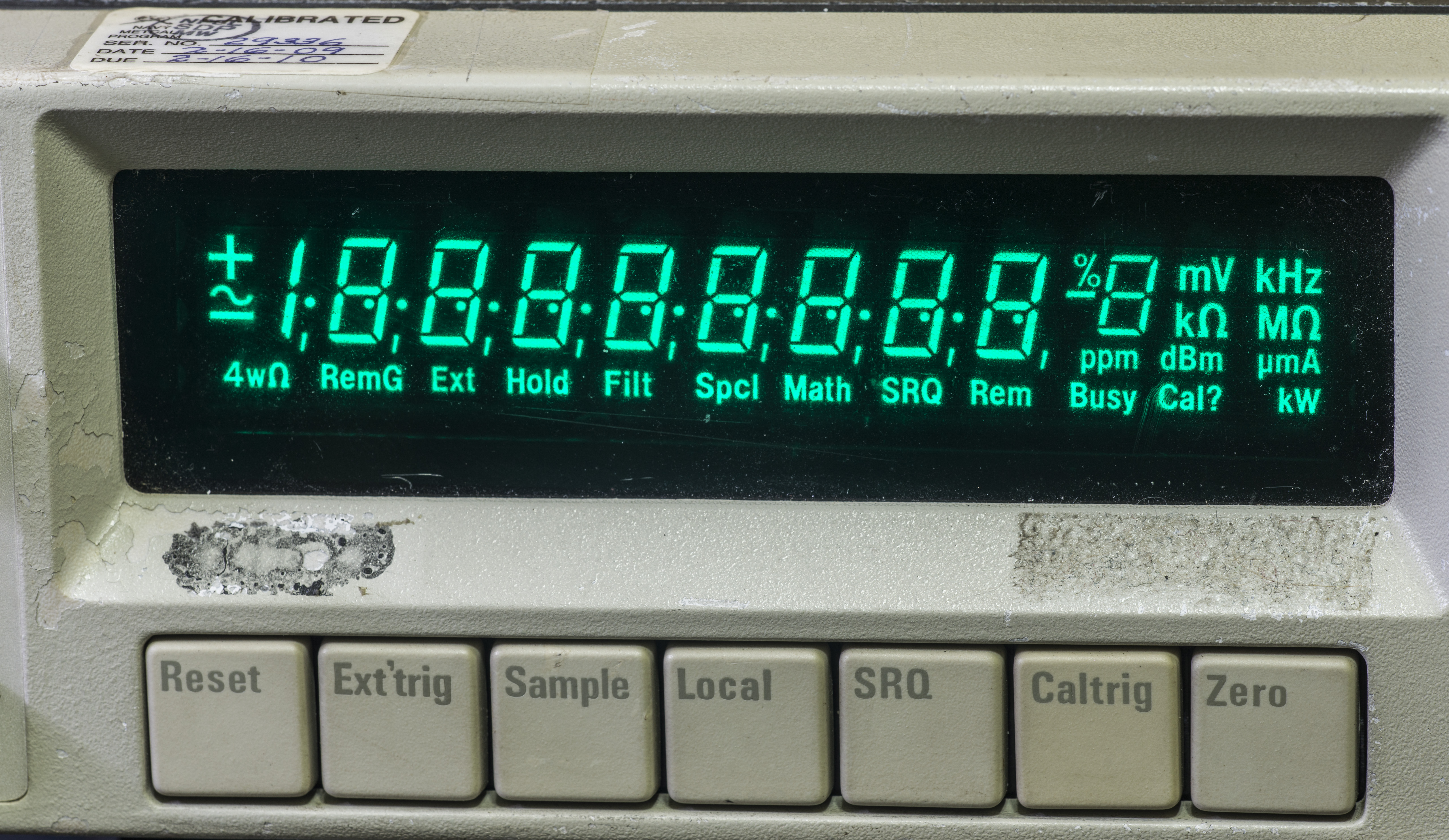
And now same signal measurement on Wavetek 4920M…
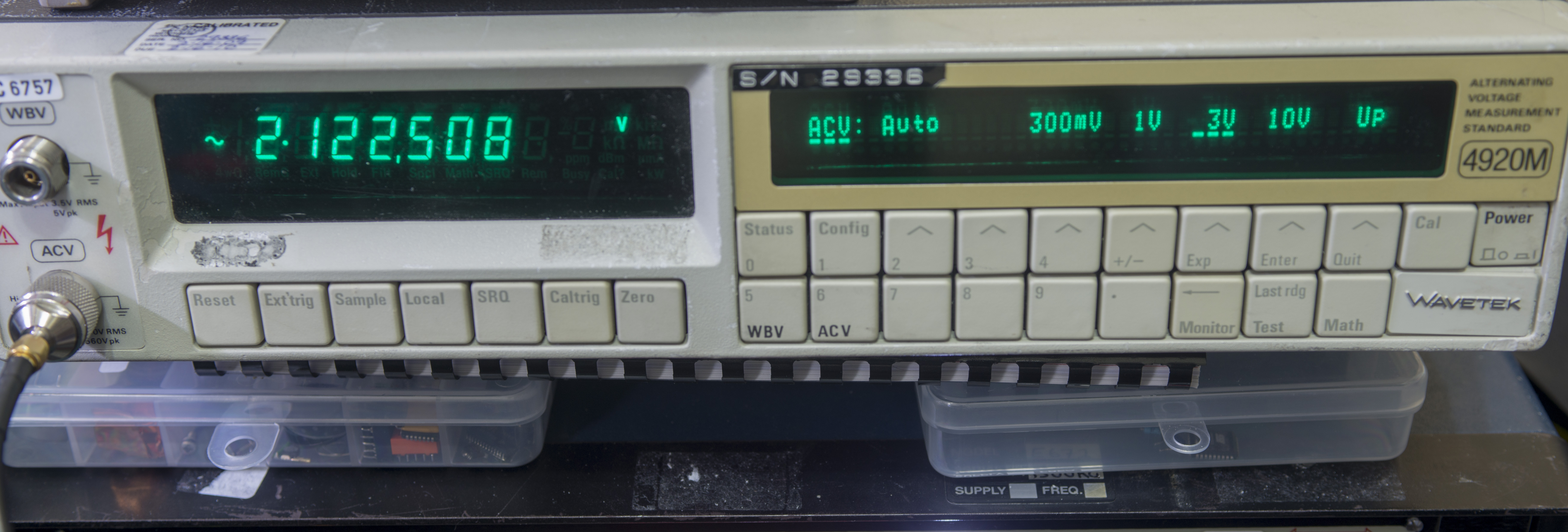
That’s not looking right!


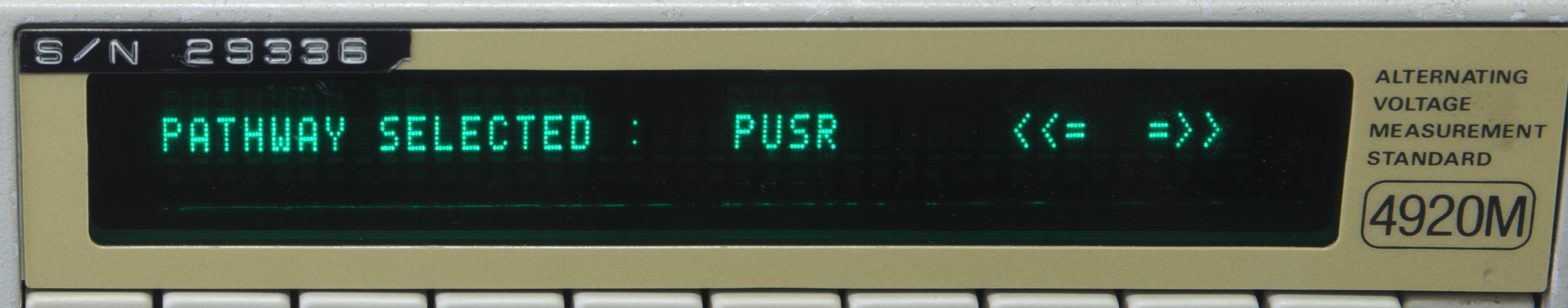
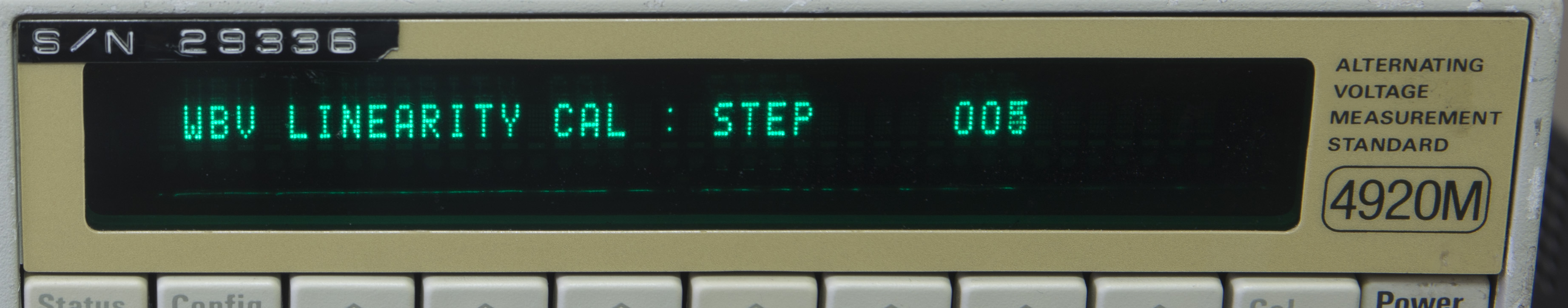
Service manual have special test modes, called Test Pathways, which allow to single-step preprogrammed measurements and comparison to specific limits set by manufacturer. This mode entered by going using keys flow ACV->10V->Status->Config->”+/-”. Aux right VFD should display PATHWAY SELECTED: PUSR <<= =>> message, and allow scrolling between various test conditions.
Test results and expected normal range shown in table below:
| Test ID | Test code | Check | Expected | Result | Condition |
|---|---|---|---|---|---|
| PUSR | 0.025264 VAC | ||||
| PWDB | 1.035890 VAC | ||||
| 4007 | PV01 | A-D Zero | <10mV | 0.000118 VAC | In spec |
| 4008 | PV02 | +15V | +4.5V < x < +5.5V | 4.981180 | In spec |
| 4009 | PV03 | -15V | -5.5V < x < -4.5V | -4.979565 | In spec |
| 4010 | PV04 | REF 2 A-D | 6.45V < x < 7.45V | 7.064100 | In spec |
| 4011 | PV05 | VREF2_POS | 1.760 < x < 1.860 | 1.855043 | In spec |
| 4012 | PV06 | VREF2_NEG | -1.860 < x < -1.760 | -1.854307 | In spec |
| 4013 | PV07 | +11V A-D | +6.550V < x < +8.010 | 7.3333128 | In spec |
| 4014 | PV08 | -19V A-D | -7.22V < x < -6.12 | -6.660199 | In spec |
| 4015 | PA01 | AC Preamp x1 Zero | < 1mV | -0.000103 | In spec |
| 4016 | PA02 | AC Preamp x3 Zero | < 3mV | -0.000651 | In spec |
| 4017 | PA03 | AC Preamp 1V +Gain | +0.850 < x < +1.050V | 1.001059 | In spec |
| 4018 | PA04 | AC Preamp 1V -Gain | -1.050 < x < -0.850 | -0.997801 | In spec |
| 4019 | PA05 | AC Preamp x3 Gain | +2.550 < x < +3.15V | 3.001840 | In spec |
| 4020 | PA06 | AC Preamp 10V Atten | -1.950 < x < -1.550 | -1.725347 | In spec |
| 4021 | PA07 | AC Preamp 100V Atten | -0.950 < x < -0.155 | -0.173015 | In spec |
| 4022 | PA08 | AC Preamp 1kV Atten | -0.032 < x < -0.020 | -0.025547 | In spec |
| 4023 | PA09 | AC Preamp AC Freq counter | < 1000ppm | 7.064100 | In spec |
| 4024 | PA10 | AC Preamp AC Overload Det | > +6V | 8.257538 | In spec |
| 4025 | PA12 | AC Preamp AC Overload Op | < 50mV | -0.016837 | In spec |
| 4026 | PA13 | WB 50Ω Input Match HF DC | < -1.9V | -1.017076 | In spec |
| 4027 | PA14 | AC RMS Detector – loop | 2.400V < x < 3.000V | 2.798327 | In spec |
| 4028 | PA15 | AC RMS Detector – S&H track | PA14-10mV < x < PA14+10mV | 2.797599 | In spec |
| 4029 | PA16 | AC RMS Detector – Hold check | PA15-10mV < x < PA15+10mV | 2.798572 | In spec |
| 4030 | PA17 | AC RMS Detector – Quasi-Sine | PA15-150mV < x < PA15+150mV | 2.810350 | In spec |
| 4031 | PA18 | AC RMS Conversion – Full measurement 100Hz | 2.550V < x < 2.850V | 2.785329 | In spec |
| 4033 | PA20 | AC RMS Conversion – Full measurement 10Hz | PA18-30mV < x < PA18+30mV | 2.788208 | In spec |
| 4035 | PA22 | AC RMS Conversion – Linearity (10V) | 2.350 < x < 2.450 V | 0.242792 | FAIL |
| 4036 | PW01 | WB DAC +ve Zero | < ±2mV | 0.000114 | In spec |
| 4037 | PW02 | WB DAC -ve Zero | < ±2mV | 0.000135 | In spec |
| 4038 | PW03 | WB DAC +ve FS | 3.47V < x < 3.85V | 3.824203 | In spec |
| 4039 | PW04 | WB DAC -ve FS | -PW03 ±100mV | -3.823763 | In spec |
| 4040 | PW05 | WB DAC +3.5V | 3.31V < x < 3.69V | 3.657724 | In spec |
| 4041 | PW06 | WB DAC -3.5V | -PW05-10mV < x < -PW05 + 10mV | -3.657293 | In spec |
| 4042 | PW07 | WB DAC sw +ve | PW05-1mV < x < PW05+1mV | 3.657719 | In spec |
| 4043 | PW08 | WB DAC sw -ve | PW06-1mV < x < PW06+1mV | 3.657291 | In spec |
| 4044 | PW09 | WB DAC TTU DC 3.5V | 4.67V < x < 7.47V | 6.209904 | In spec |
| 4045 | PW10 | WB DAC TTU DC 1.0V | 0.41V < x < 0.69V | 0.652755 | In spec |
| 4046 | PW11 | WB DAC TTU DC 0V | <100mV | 0.074512 | In spec |
| 4047 | PW12 | WB DAC TTU AC 0V | 0 < x < 100mV | 0.072201 | In spec |
| 4049 | PW14 | A/D WB Path check | x < -0.900V | -1.017870 | In spec |
| 4050 | PW15 | WB Path check | 0.41 < x < 0.69 V | 0.621220 | In spec |
| 4051 | PW16 | WB Input Z, DC Path check | PW14 – 1mV < x < PW14 + 1mV | -1.016650 | In spec |
| 4052 | PW17 | WB 100mV Path check | -3.1V < x < -1.7V | -2.401153 | In spec |
Linearity test PA22 failed miserably, so not everything is alright with this box. Hints of why could be revealed from calibration date stored in NVRAM:
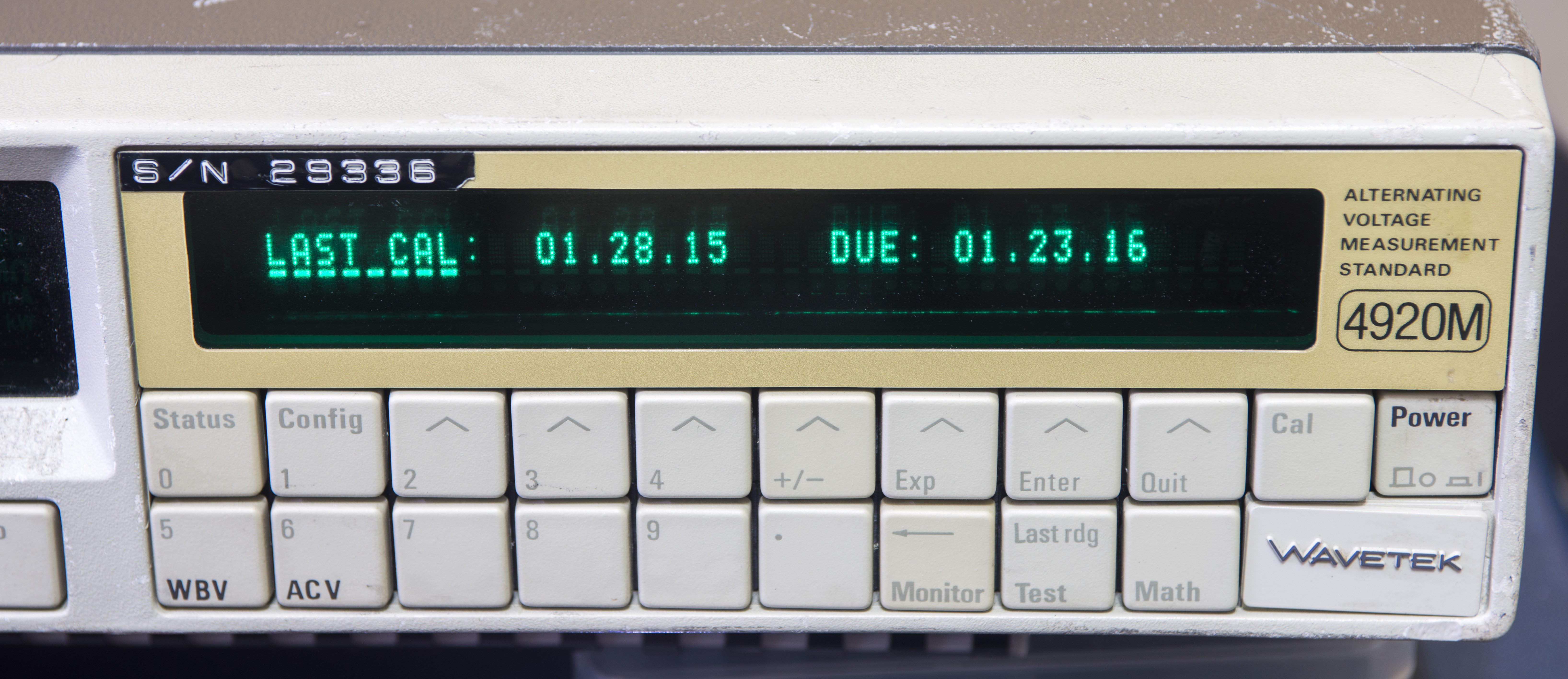
January 2015? That’s very recent in rules of broken eBay equipment. But calibration label does not agree with this date, with last calibration label as of 2009. Rear panel sticker also dictates to replace NVRAM battery in 2012.
Given that unit did not throw other errors, incorrect calibration likely the reason of invalid readings and failed linearity test. That’s both good and bad news. Good news that unit likely be in good shape and functionally good. Bad news is requirement of tedious and time consuming calibration procedure for each range and frequency points. Worst part is that I don’t currently have suitable standards or calibrated TVC set to perform such a calibration. Also high-voltage ranges require high-frequency high-voltage source, which is not a common thing. Even traditional metrology Fluke 5720A + 5725A unable to provide more than 700 VAC at 100 kHz. Best source we have is HP 3245A with 1:10 amplifier which can go up to 1 MHz, so some more equipment or post-amplification is required.
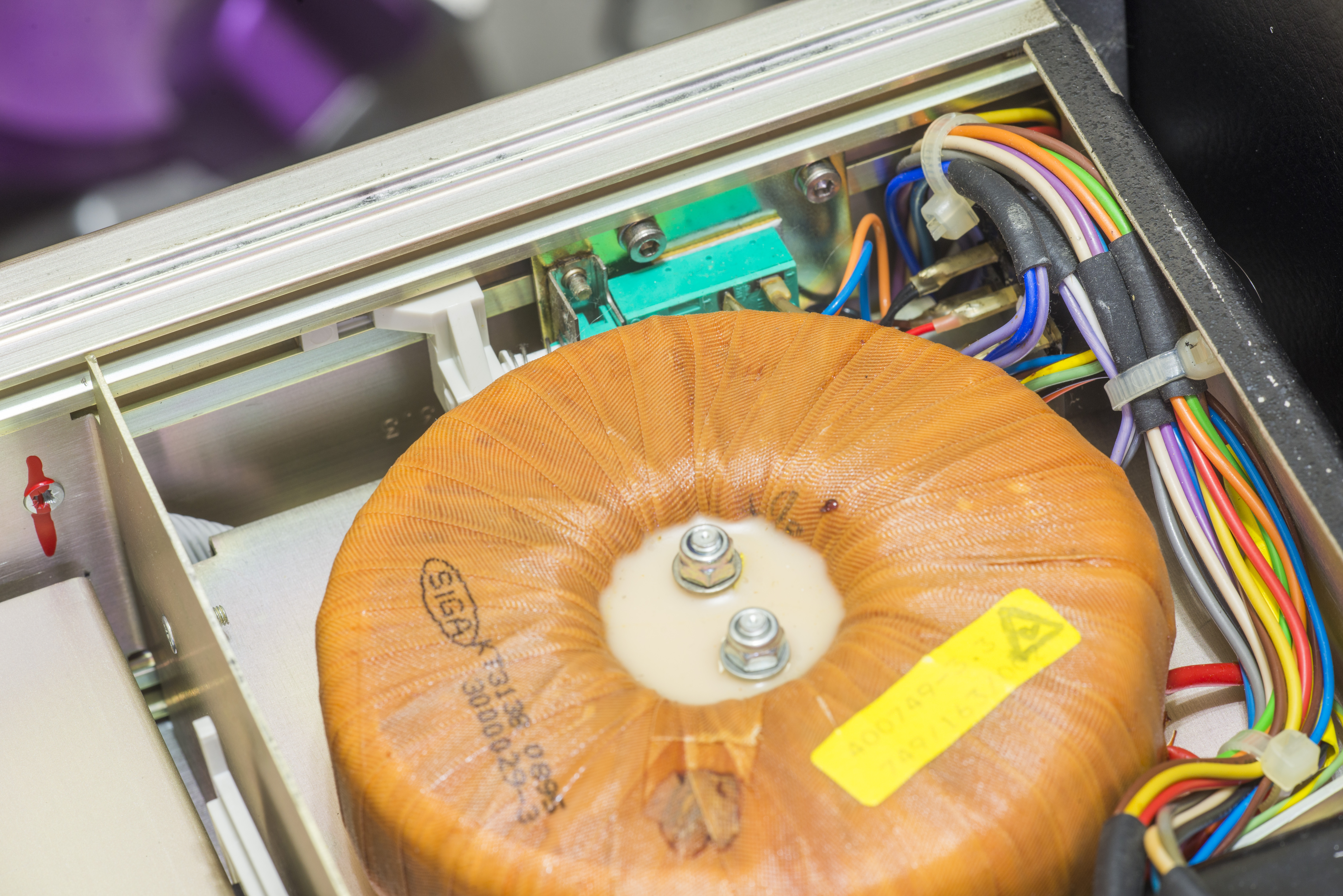
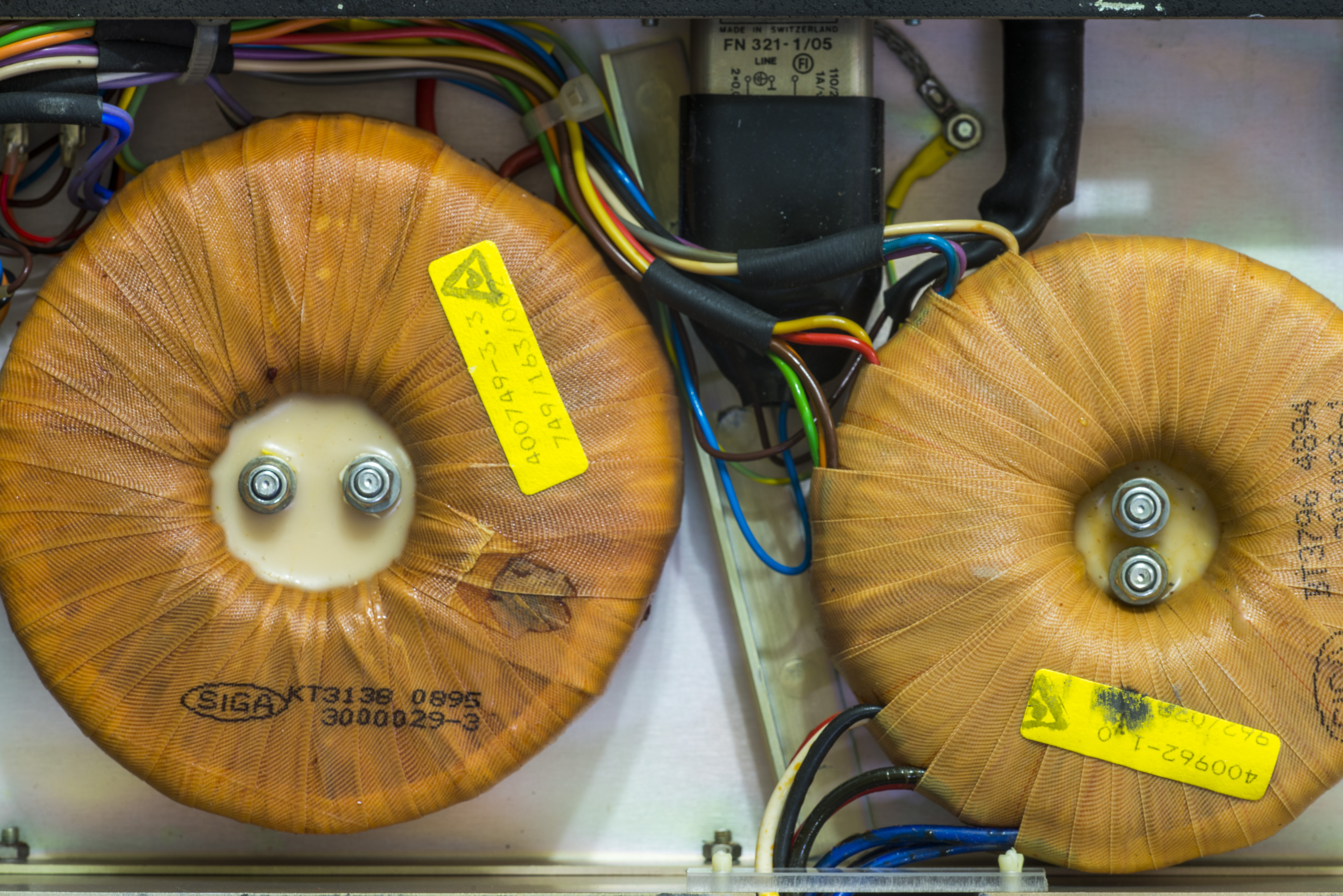
Mains power supply
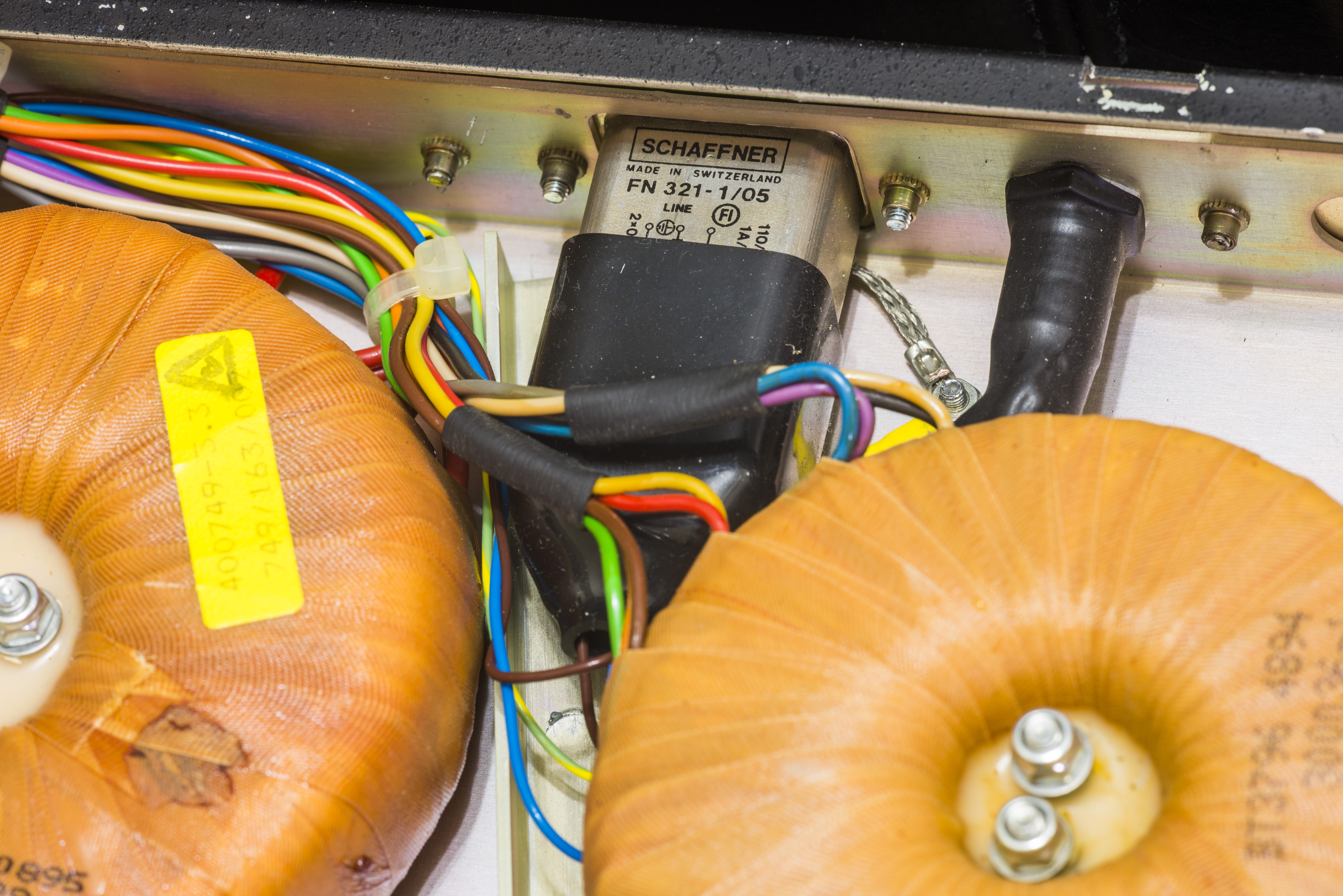
“Paffner”! For those who not aware, many of old Schaffner mains IEC filters manufactured around 90’s had bad capacitors which could led to damage and even fire! Since metrology-grade instruments like 4920 are often expected to be running 24/7 unattended, such failure may be very expensive adventure. Such examples were already reported before by users. Will be replaced with brand new 1st tier vendor filter during service, such as this EPCOS B84771A1A
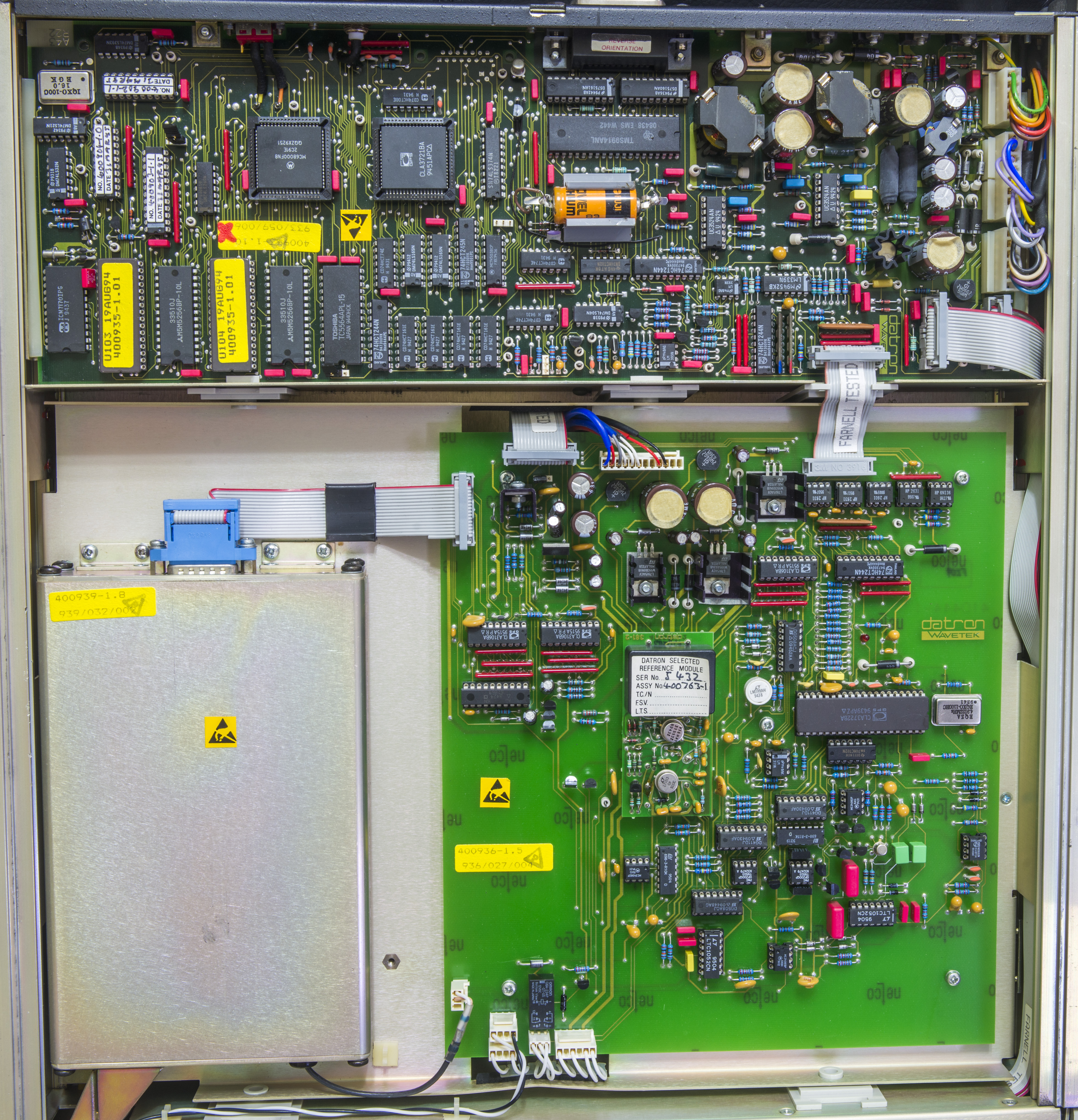
Isolation switching power converter is located on Digital PCBA. This is done to further decouple primary and secondary, using physically separate power transformers. This rare method used in other Datron instruments as well, such as 1271/1281 and modern successor – Fluke 8508A. Two separate SMPS blocks are used, with UC3524A PWM controllers. Power stage for second low-voltage transformer primary use BJT set of Q502/Q503 + Q504/Q505 (2N5550+TIP31C pairs).
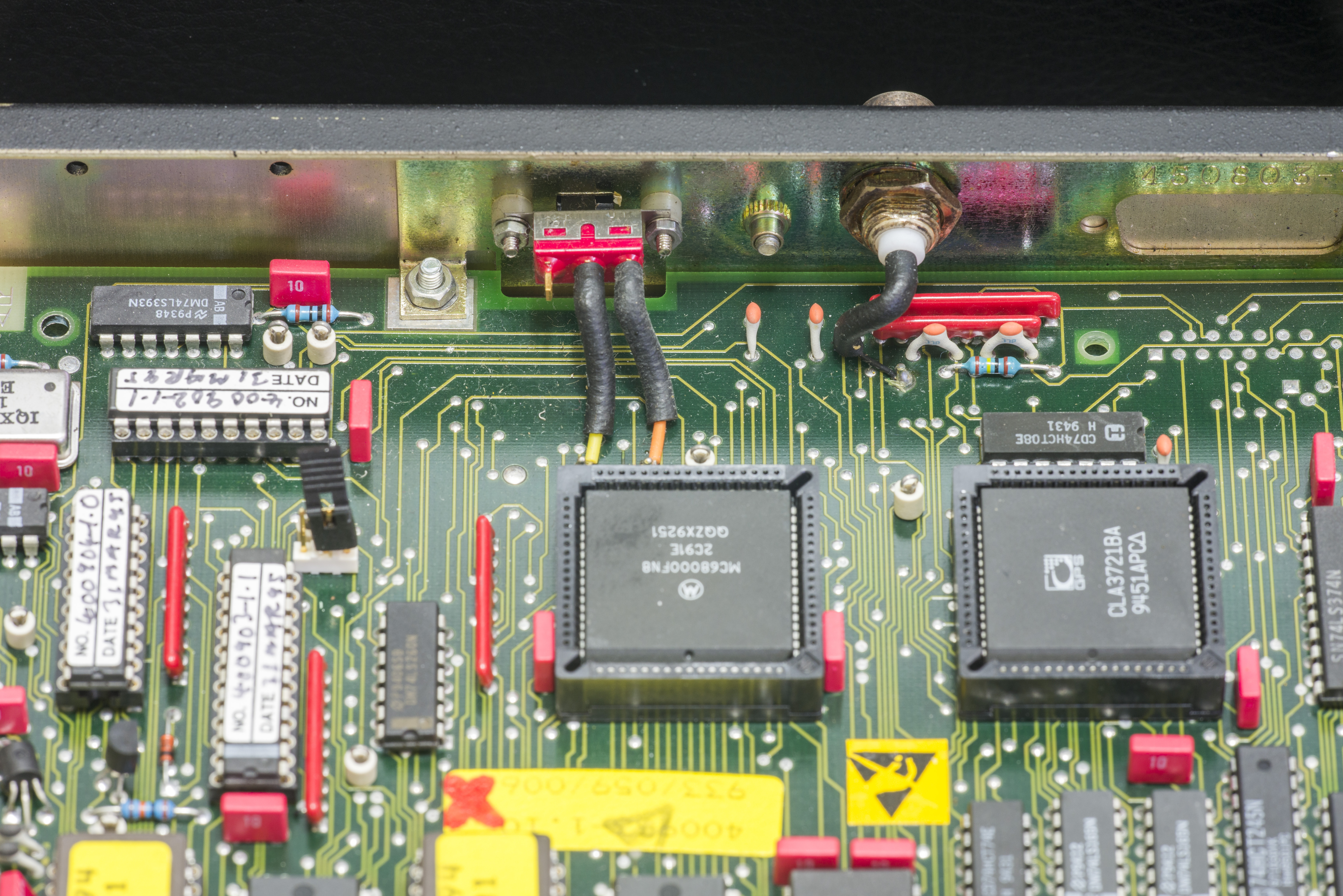
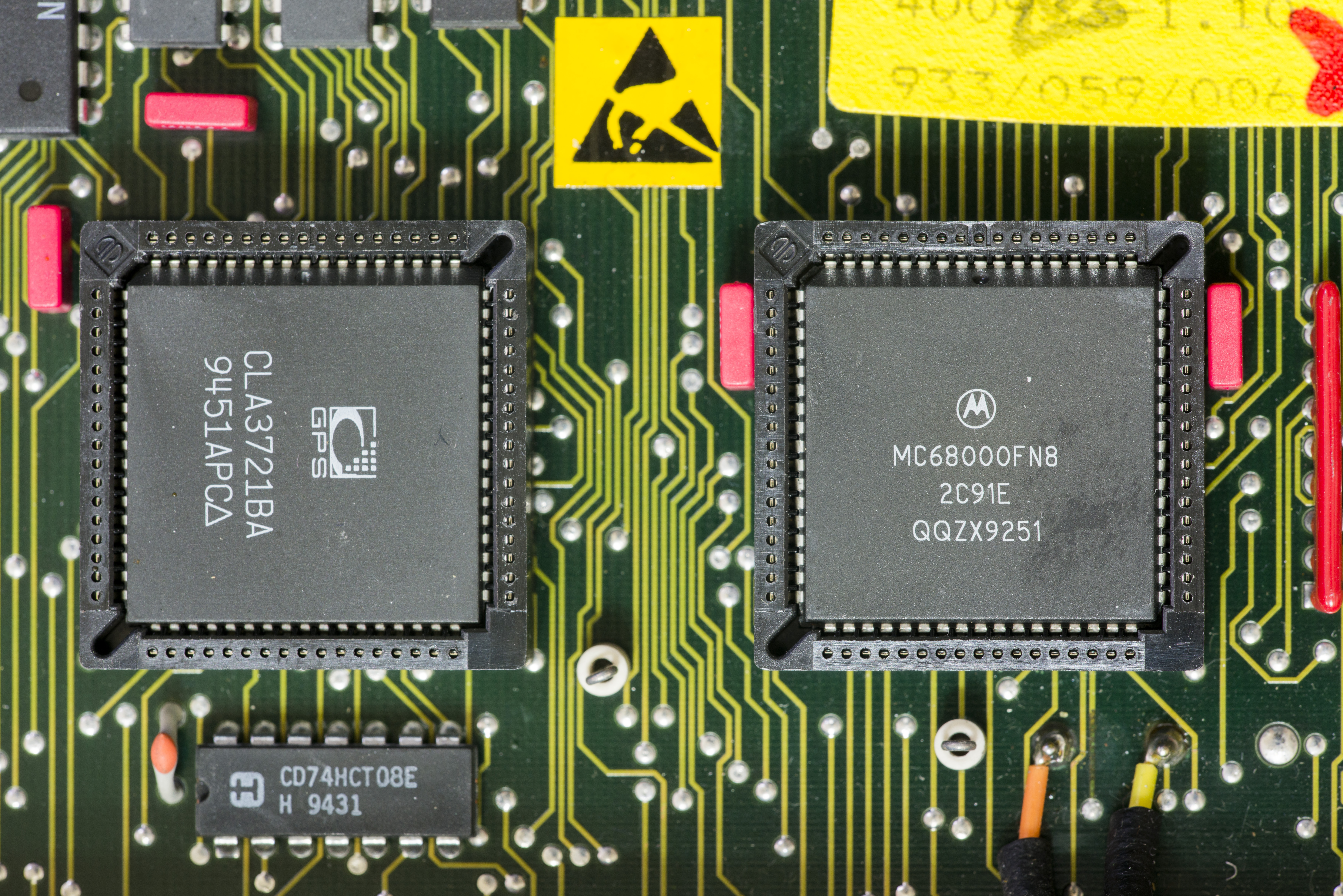
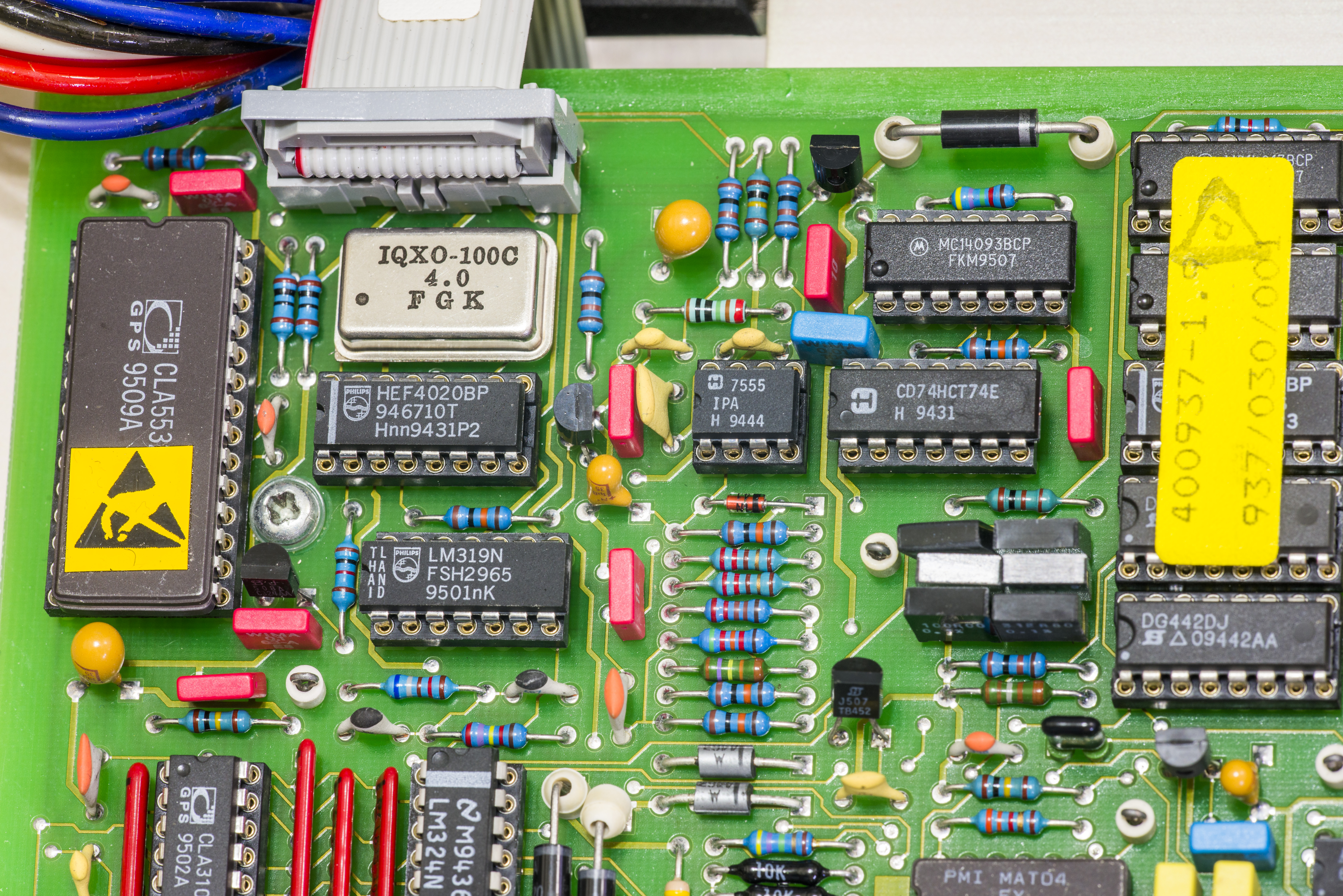
Digital PCBA – 400933
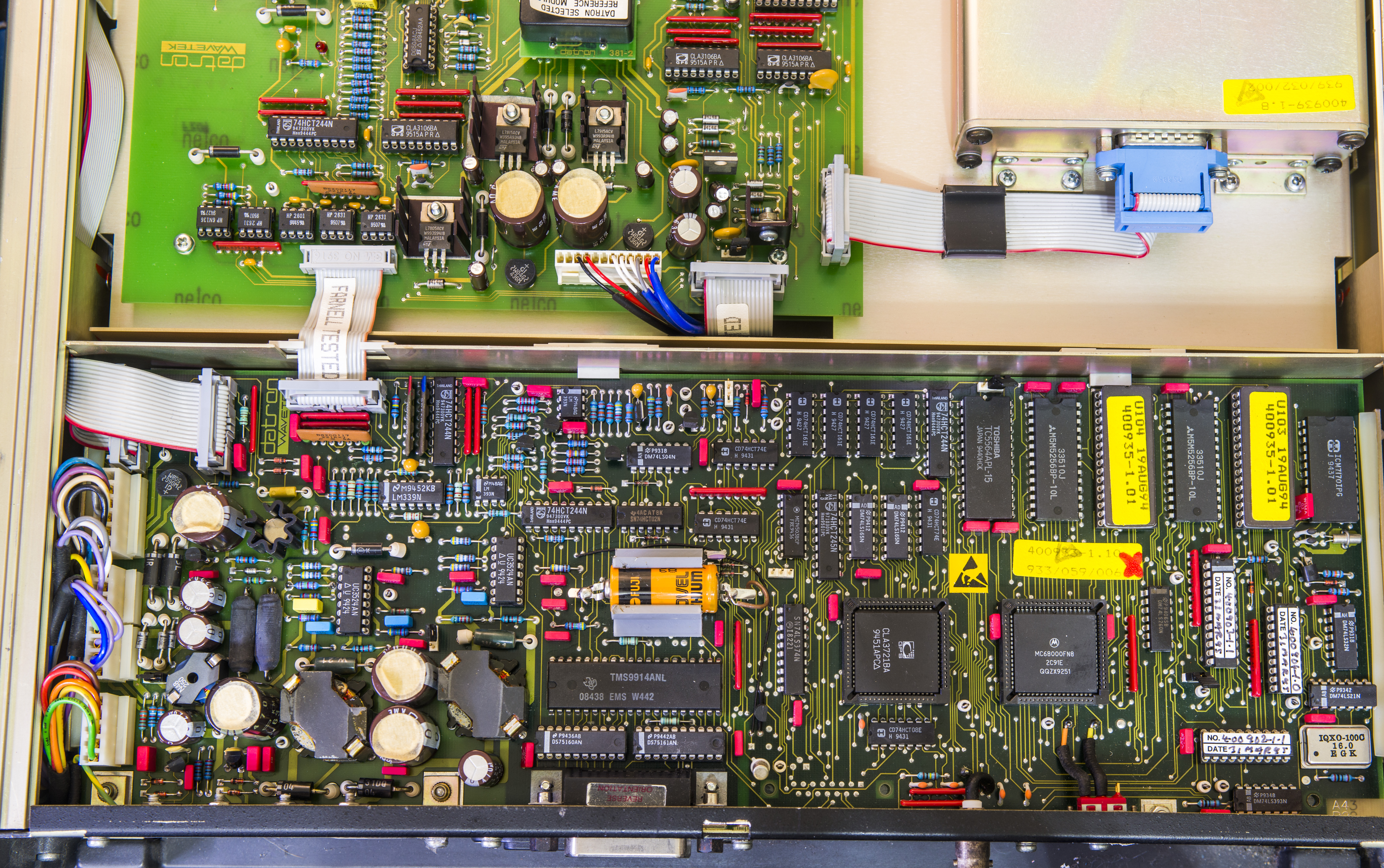
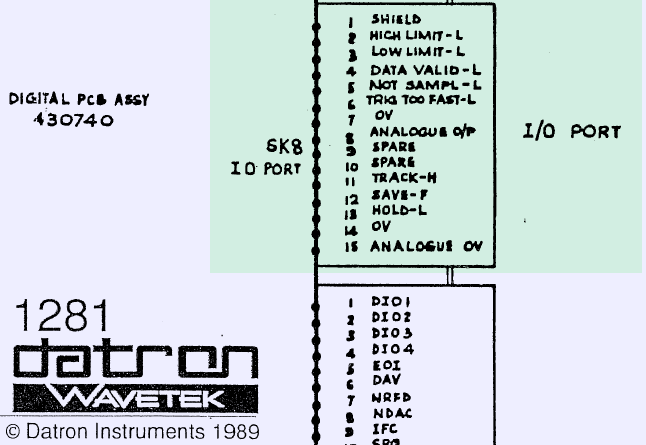
There is visible unpopulated DB15 footprint next to GPIB connector. 4920’s service manual does not list any components related to that area either. But from Datron 1281 documentation we know it’s an I/O port. Interesting enough, related to this I/O port 74LS374 is left populated.
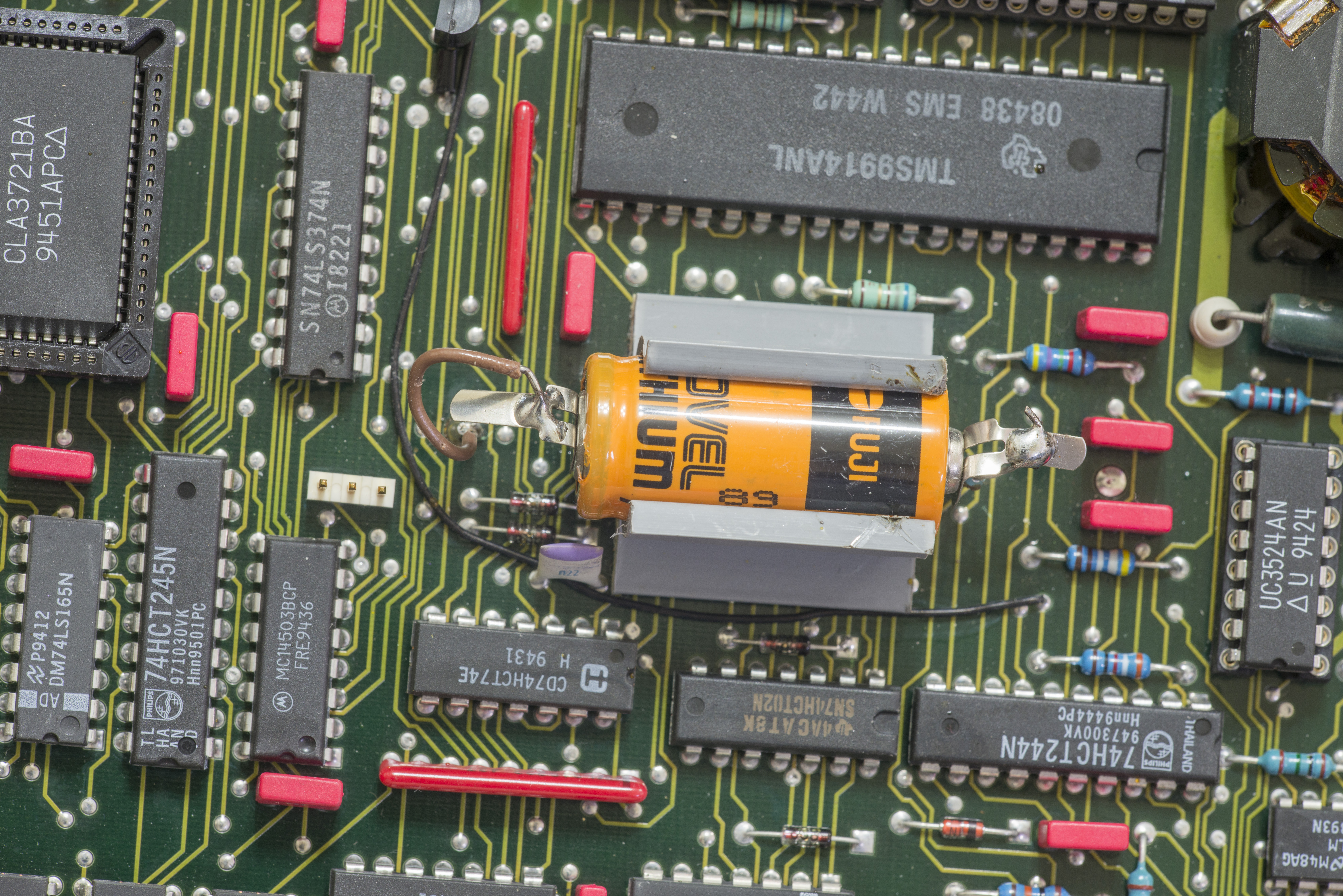
The “Intersil ICM7170”: is a real time clock, compatible with 8-bit microprocessor bus. It keeps real-time date and time and can generate periodic interrupts (100Hz, 10Hz, …) if required.

4920M has common GPIB IEEE-488 interfaces, with traditional TMS9914A and DS75161AN + DS75160AN transceivers. Serial interface to analog board implemented with simple buffering thru U404 (74HCT244), and routed to PL3 connector.

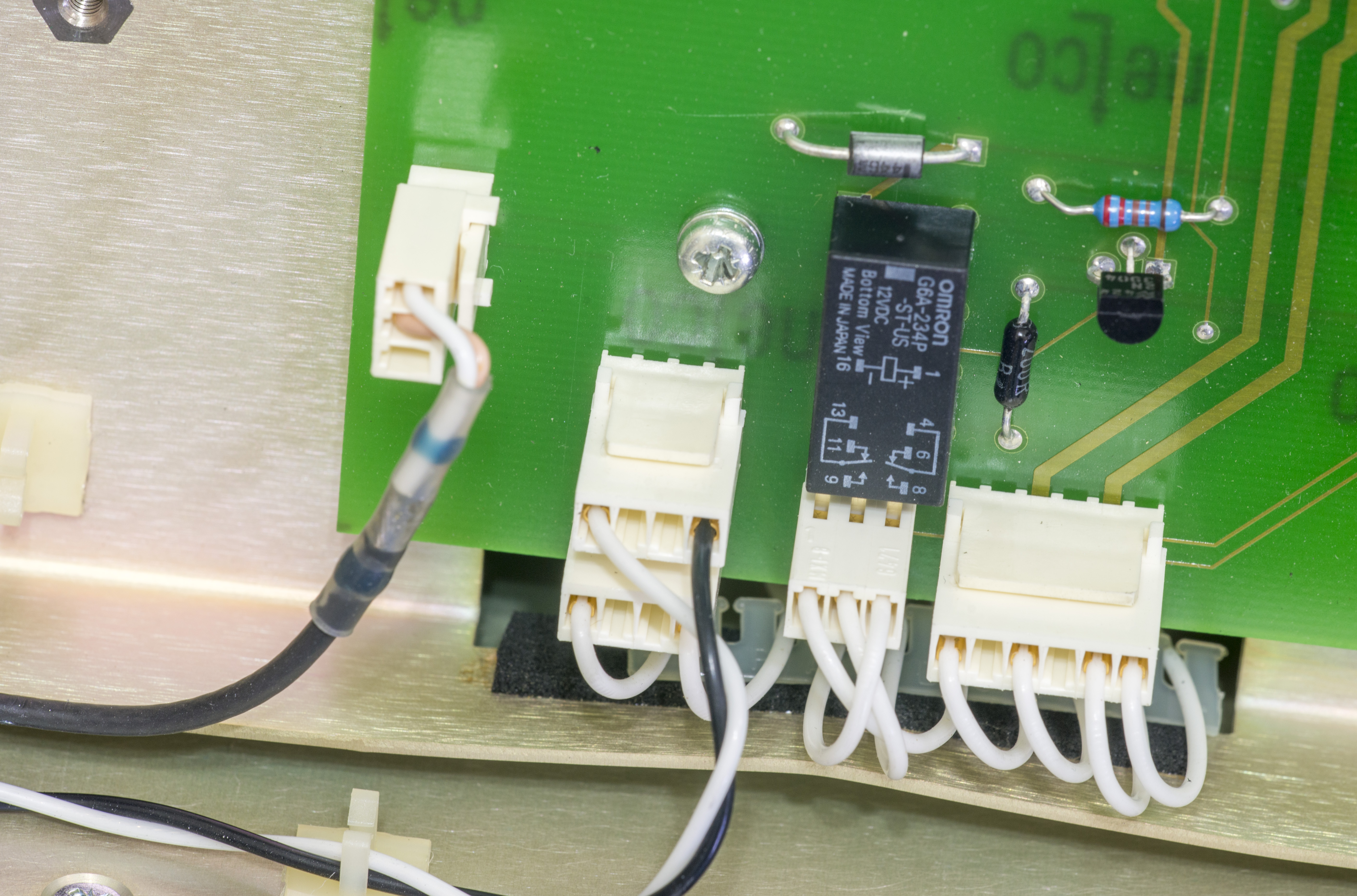
Display board – 400739
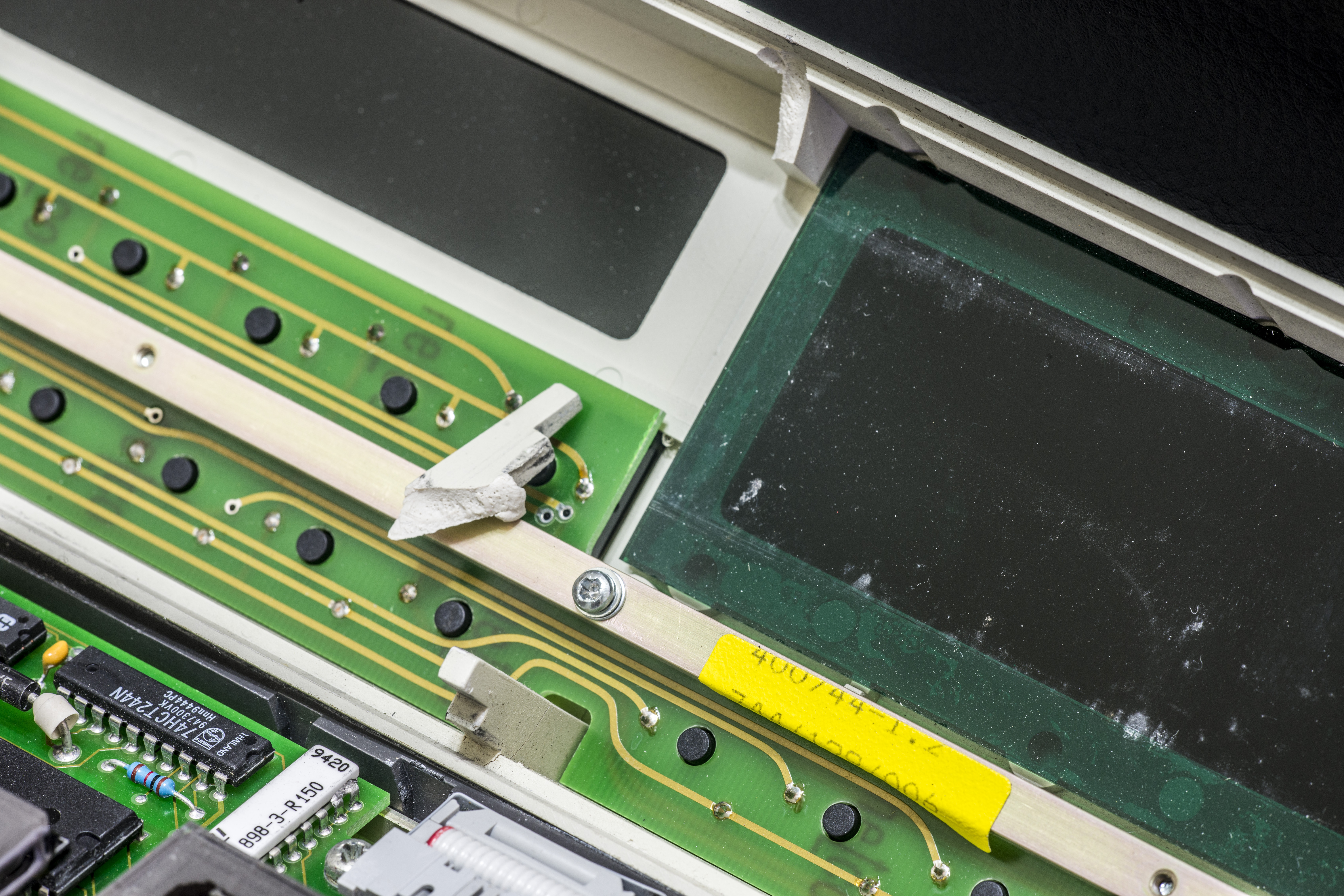
Keypad board – 400744
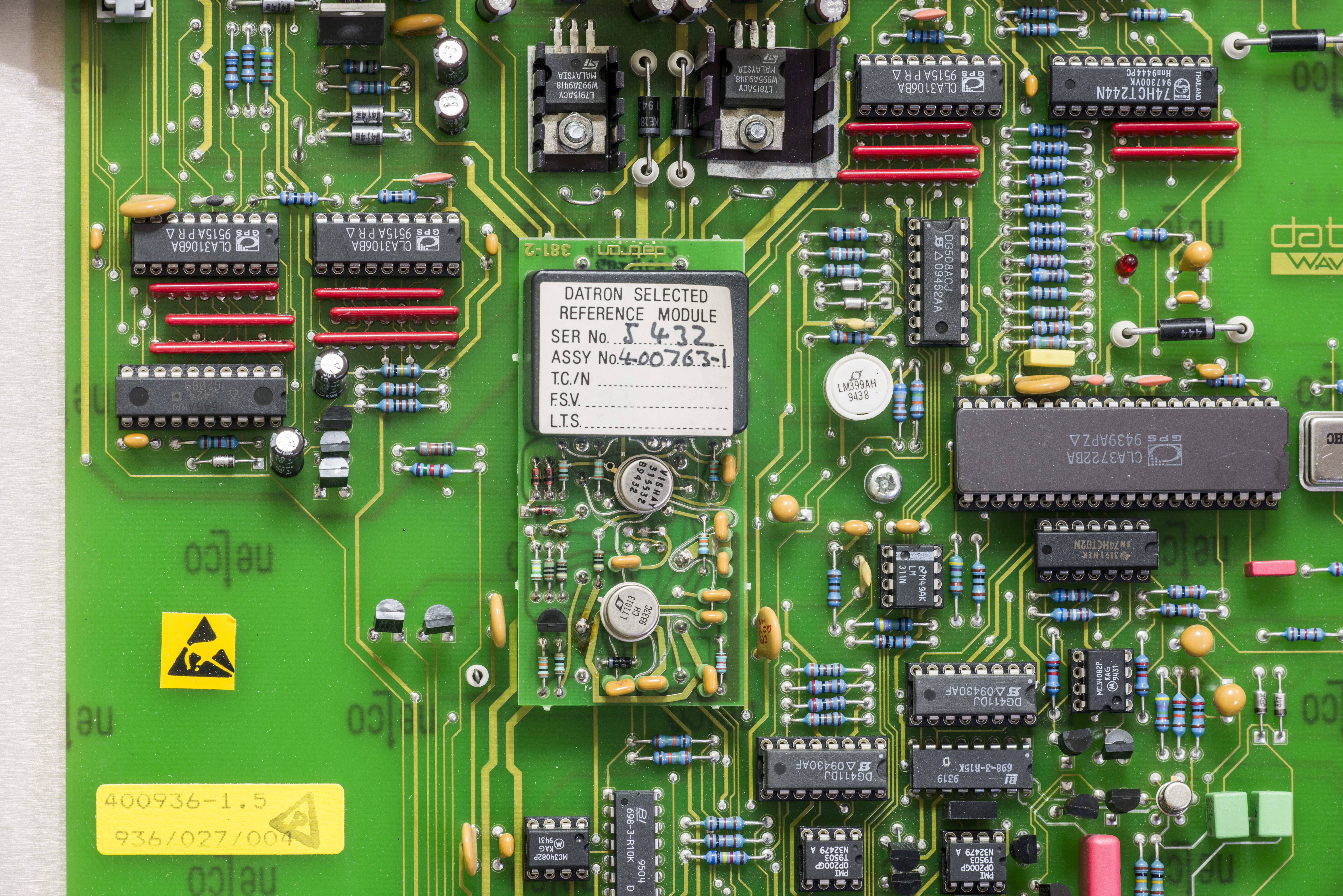
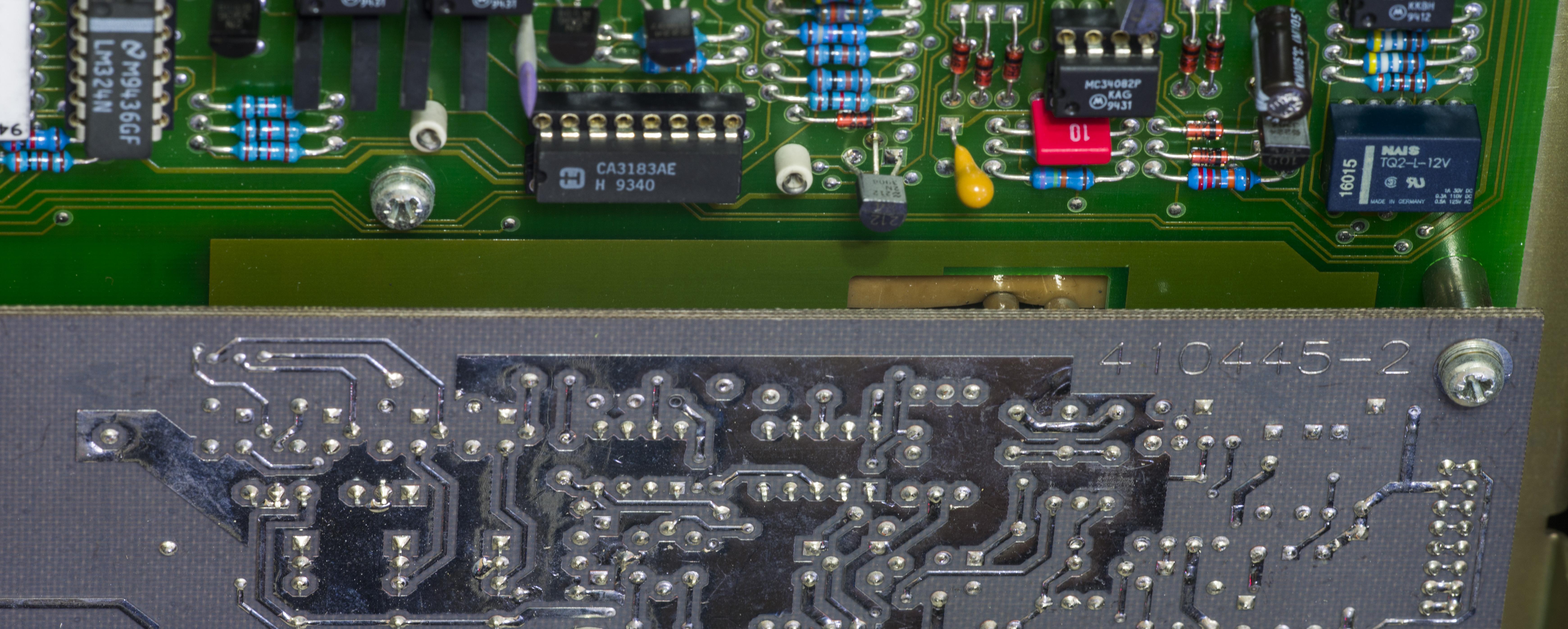
ADC and control – 400936
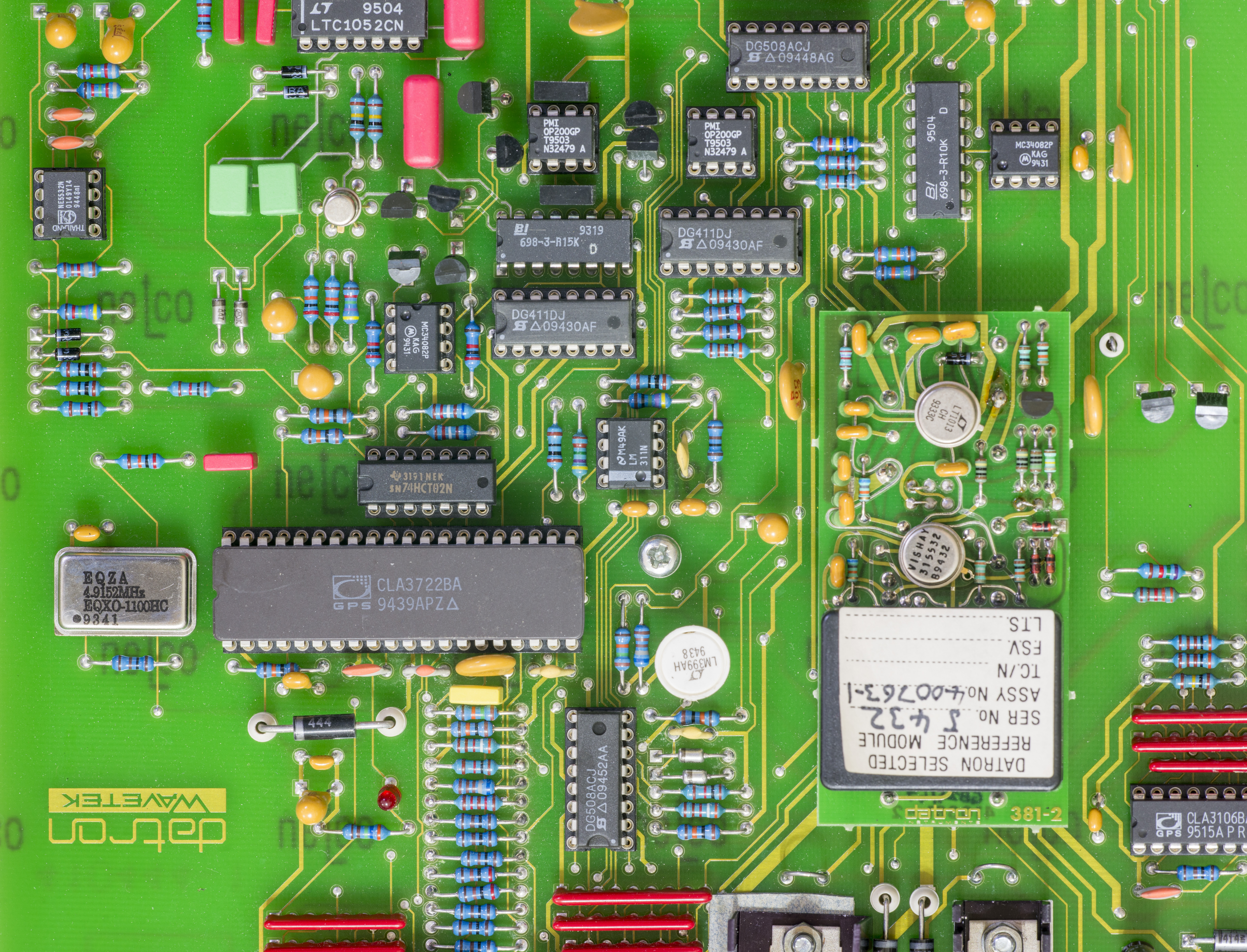

Interfacing to digital out-guard board is done thru HCPL-2631, HCPL-2601 and 6N136 optocouplers. To minimize signal amount serial data path is used. Serial datastream is converted into parallel control bus via gate arrays U607-U609 (CLA3106).
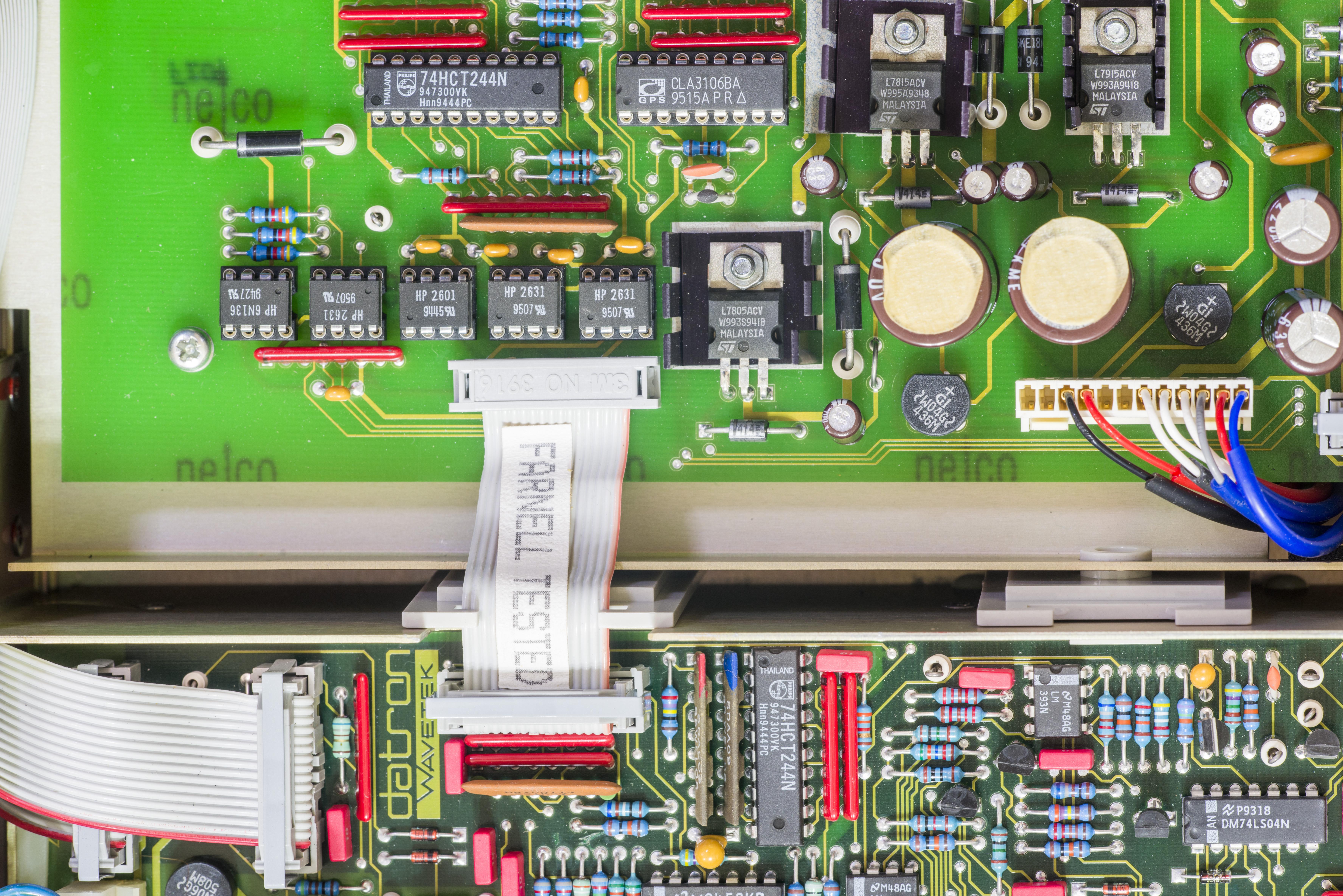
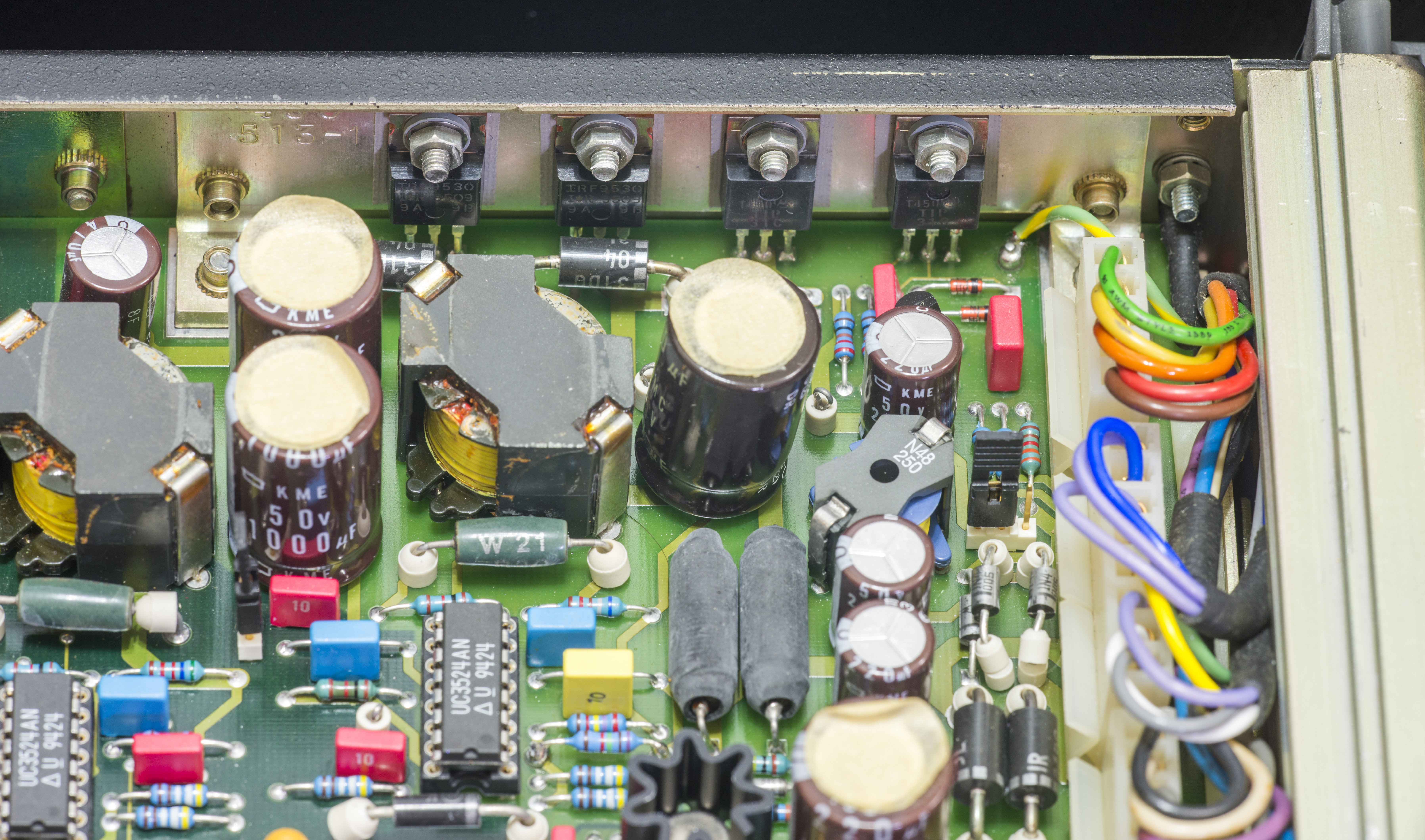
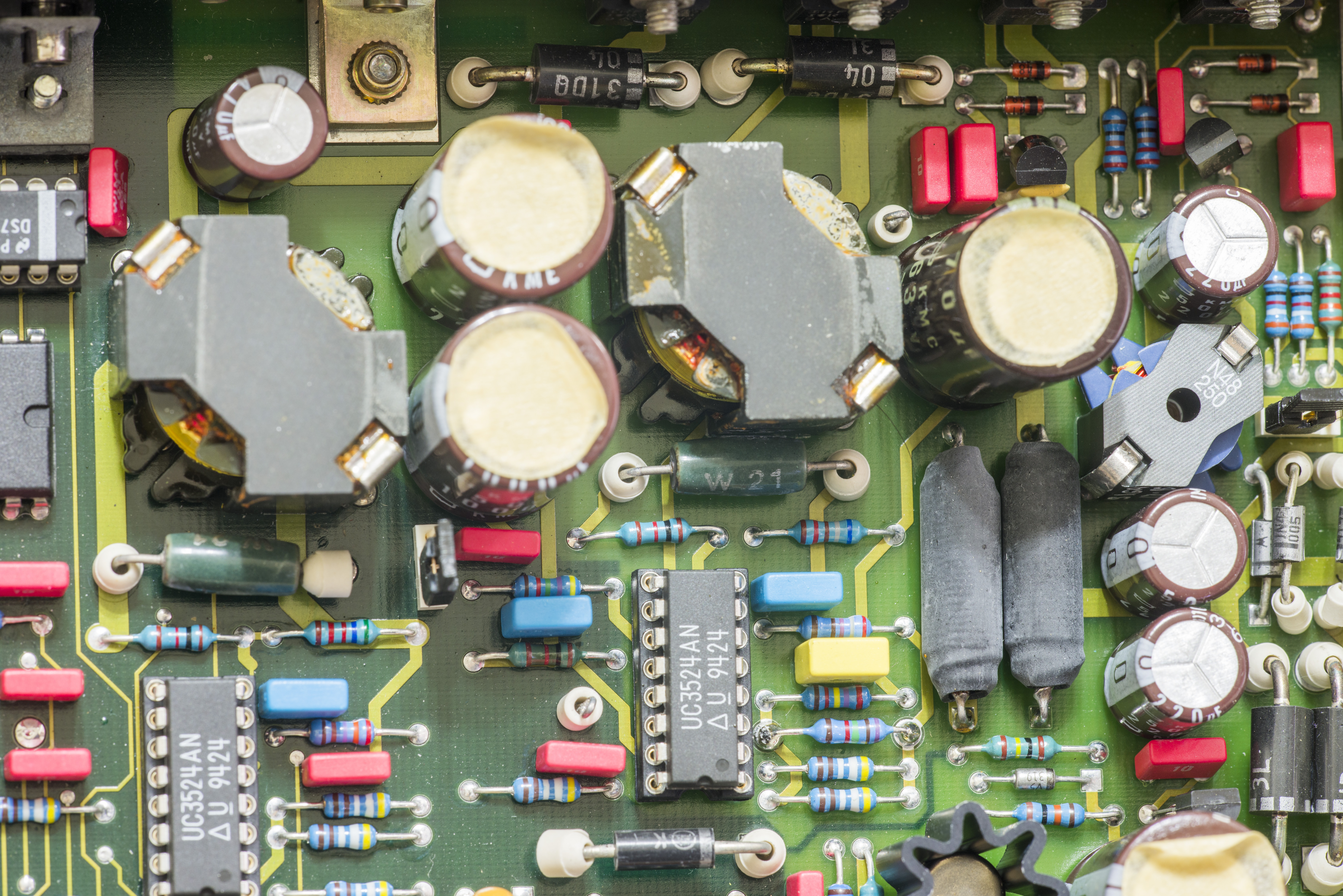
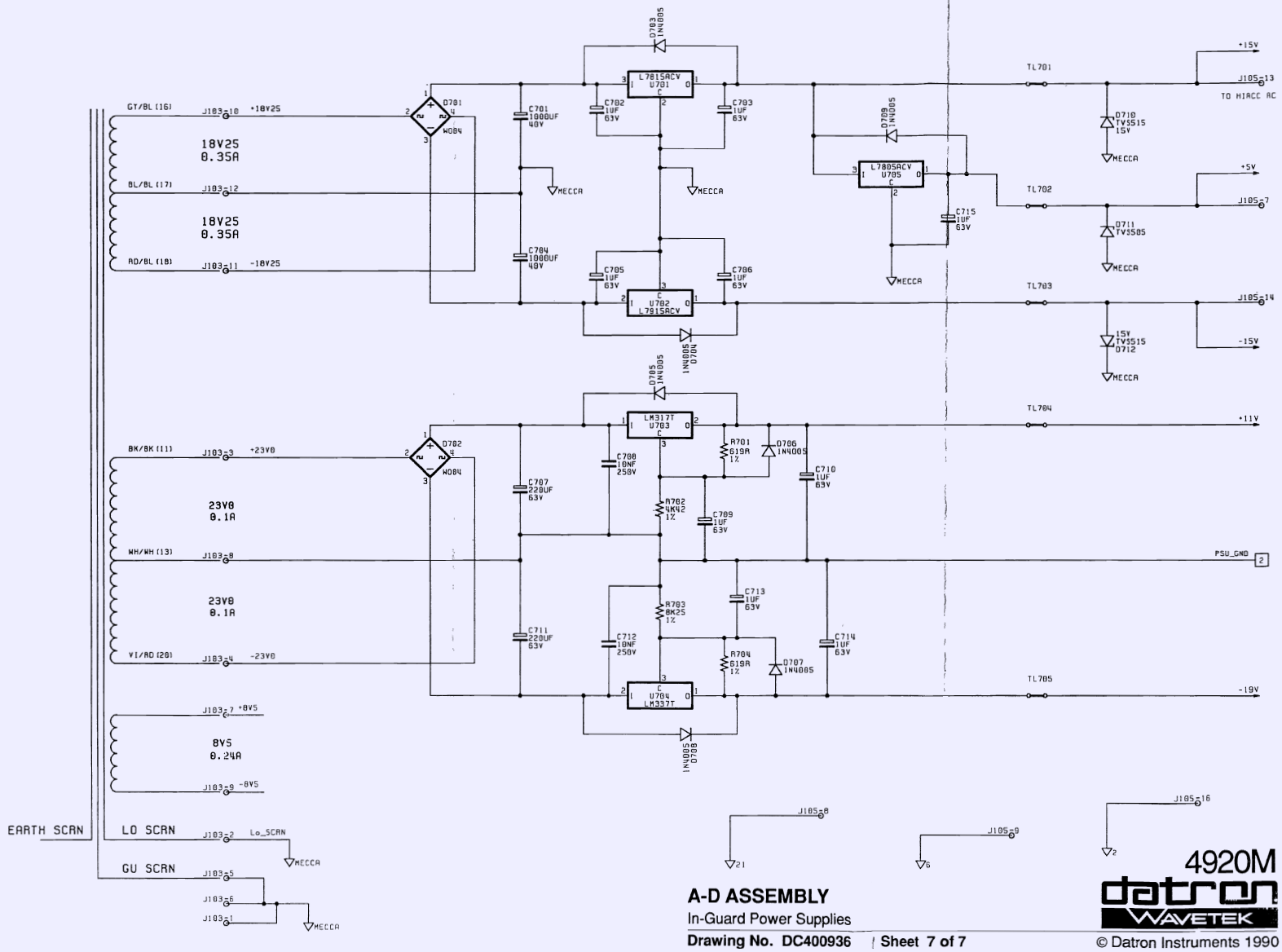
Main analog linear power regulator is located on A/D board as well, powered from inguard-section of power transformer. Two center-tap windings provide 36 VAC and 46 VAC to rectifier bridges D701,D702 and further to L7815/L7915/L7805 and LM317T/LM337T to provide +15VDC/-15VDC/+5VDC and +11VDC/-19VDC power rails.
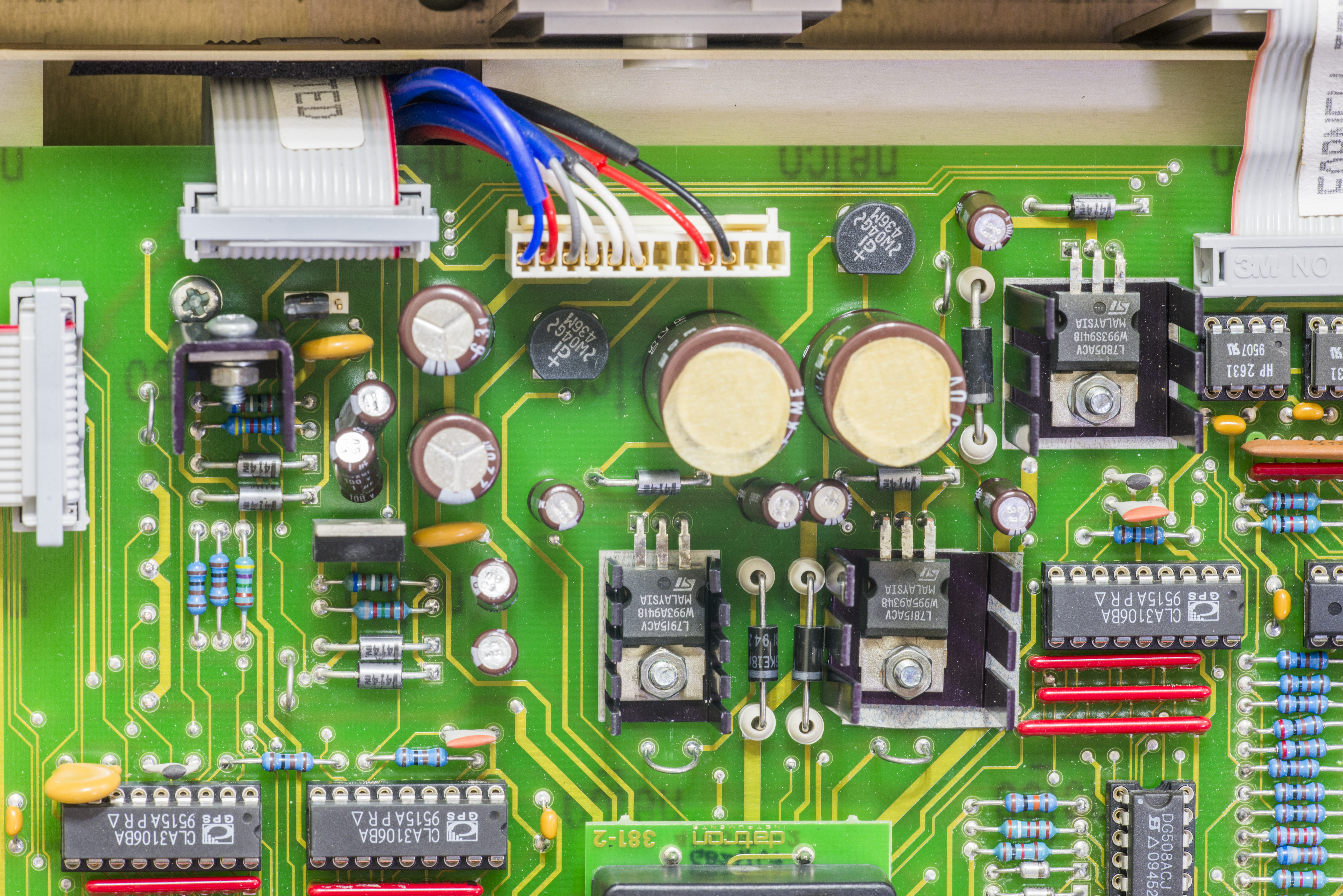
There are pair of 1000 µF 50V (marked 40V on schematics), 2 × 220 µF 63V and array of seven 1 µF 100V electrolytic capacitors around these regulators. As this instrument made in 1994, some 22 years ago, all of caps must be replaced to prevent possible damages in future. Soldering on PCB looks untouched, so previous owners did not replaced caps. Good sign for me, it’s almost always best to be first to repair :).
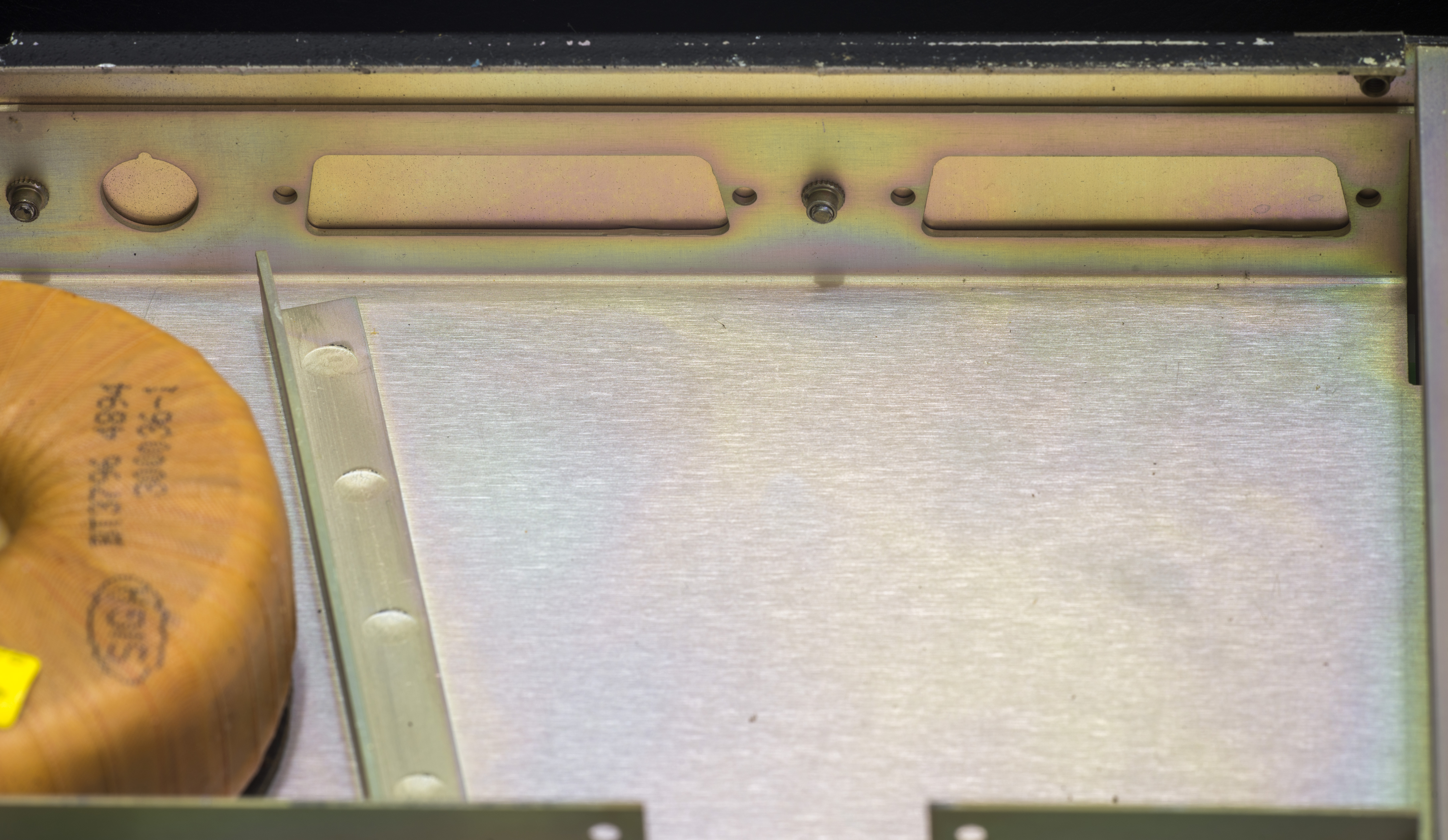
Pay attention to triple shielding of this transformer section. It’s critical to keep low capacitive and electrostatic coupling with mains and out-guard circuitry to ensure high noise rejection of analog domain. Earthed shield used to isolate outguard sections, middle shield, labeled as GU SCAN (Guard) is tied together with last electrostatic shield to analog ground MECCA LO. On Datron 1281 Guard shield on transformer was actively driven. Perhaps it was decided as excessive on 4920.
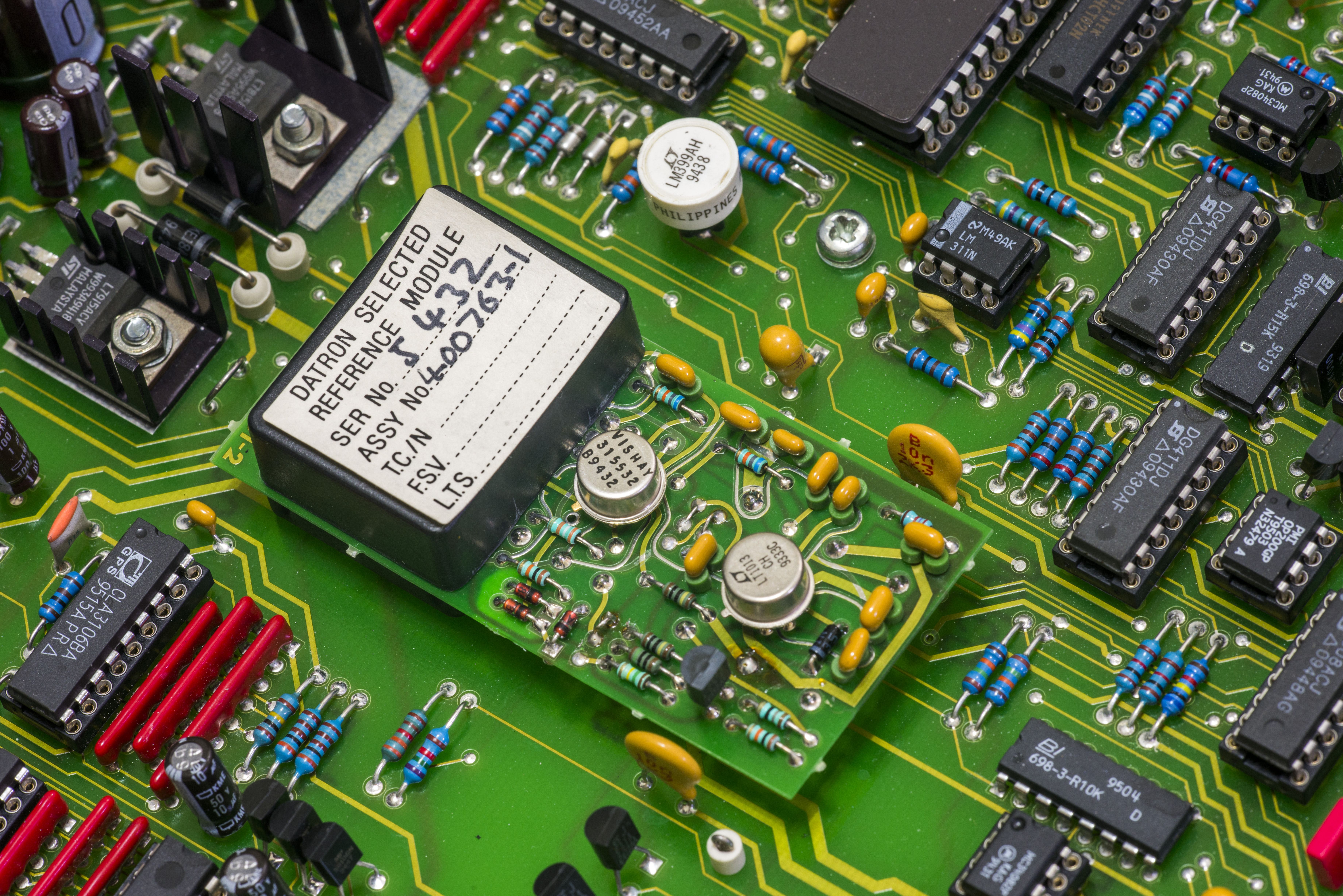
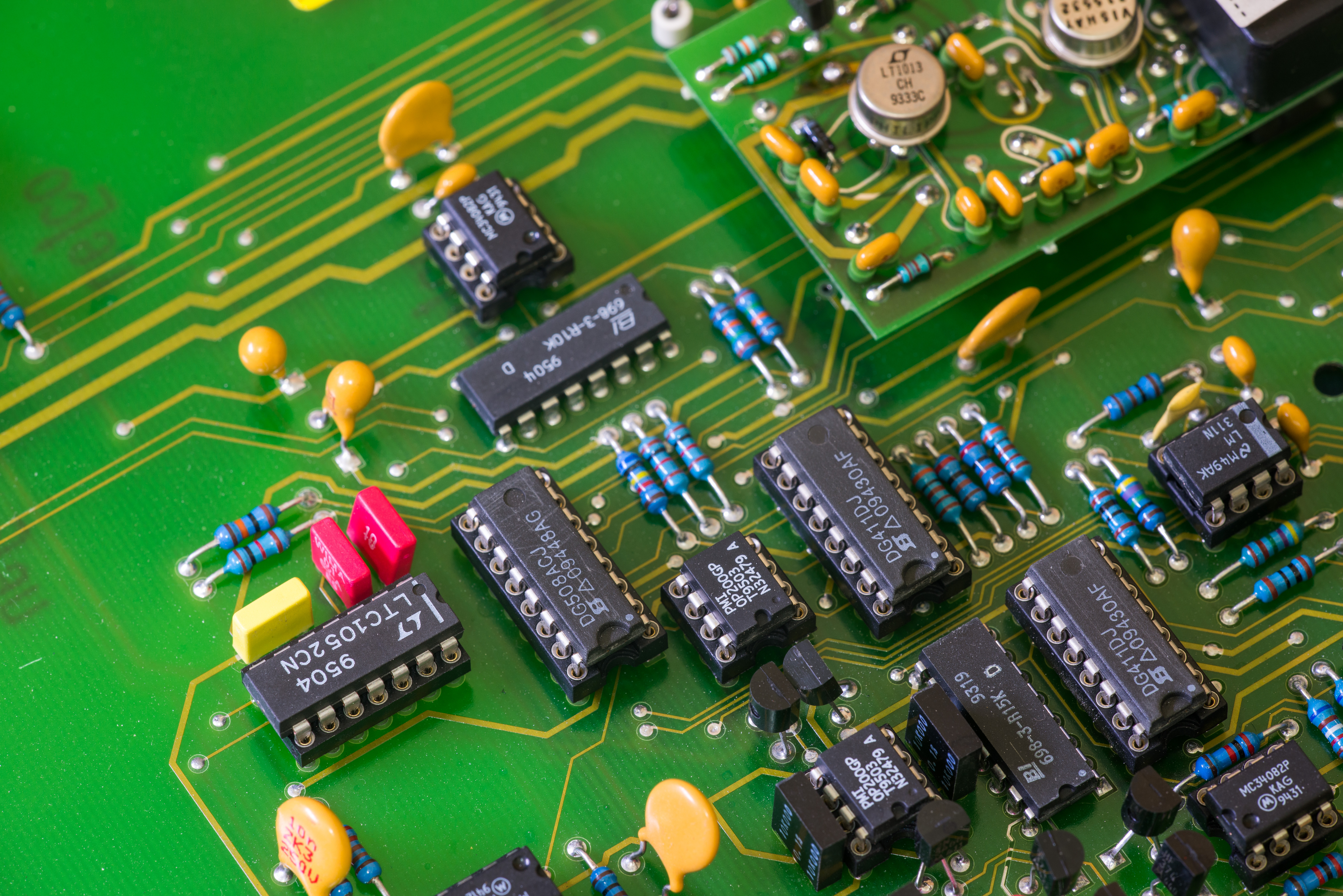
Wavetek 4920 stability and A/D resolution performance is defined by primary reference. Which is no compromise in this case, one of very best solutions based on Linear LTZ1000 Ultra-Zener reference.

PCB for LTZ DC reference module is unusually thin, to reduce thermal coupling from hot heated zener chip to rest of components on the board. Zener IC is further enclosed with plastic caps from both top and bottom sides to isolate reference from stray air drafts. Even little airflow around pins can create temperature gradient and generate unwanted thermocouple voltages at the junctions.
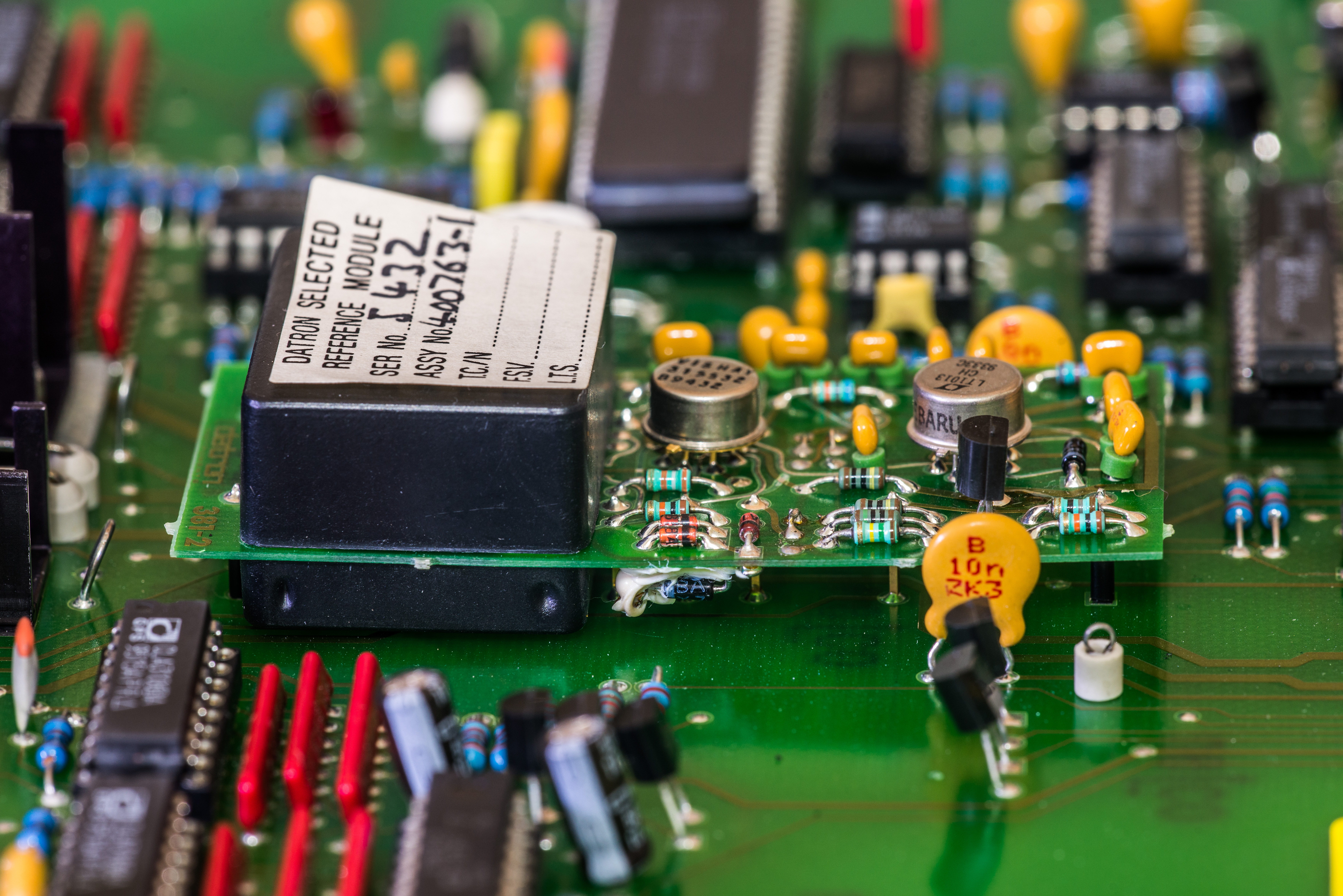
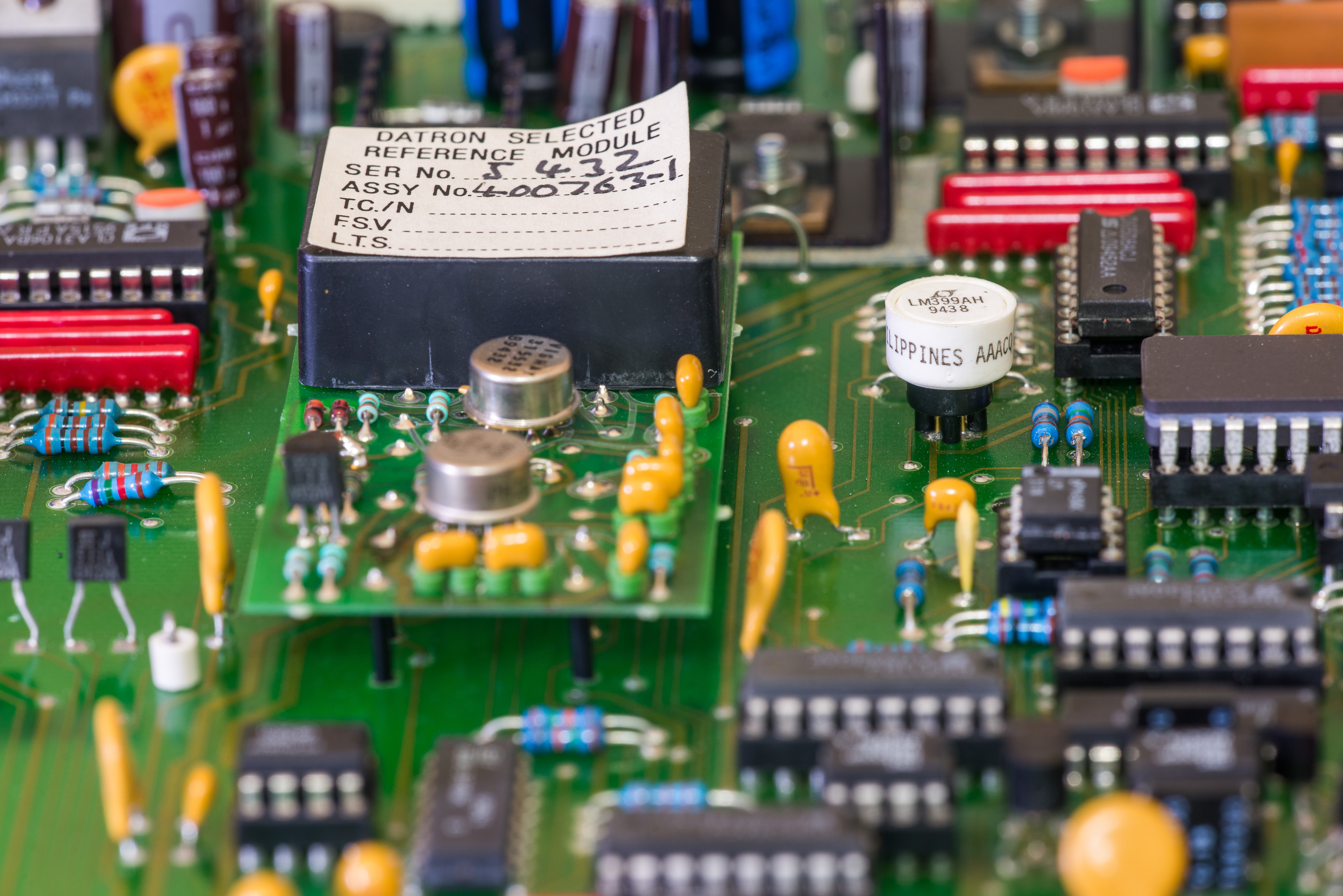
Typical drift of this ovenized 7VDC reference is in ±2 ppm/year (Wavetek manual specified ±4 ppm/year) , with typical temperature coefficient 0.15 ppm/°C. Hermetic Bulk Metal® Foil resistor network from Vishay PG and hermetic Linear LT1013 opamp ensure high performance of LTZ1000. Same reference module used in Datron 1271 and 1281 and very similar in Datron 4708/4800 series calibrators.
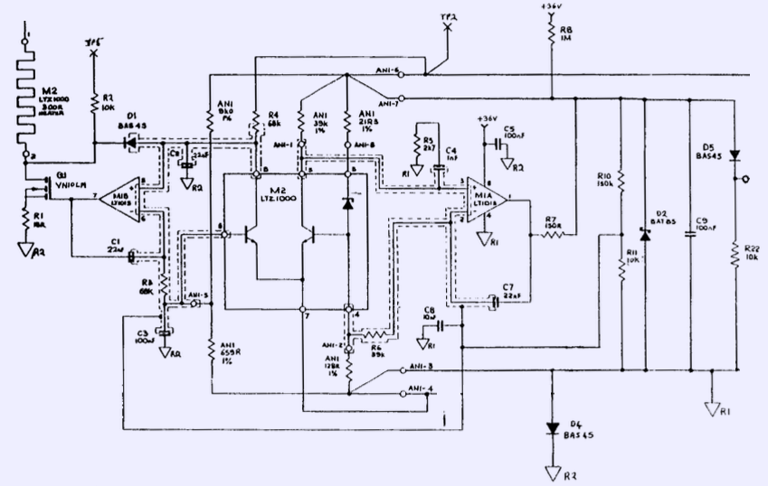
Image 4: Datron 4708 LTZ1000 primary DC voltage reference
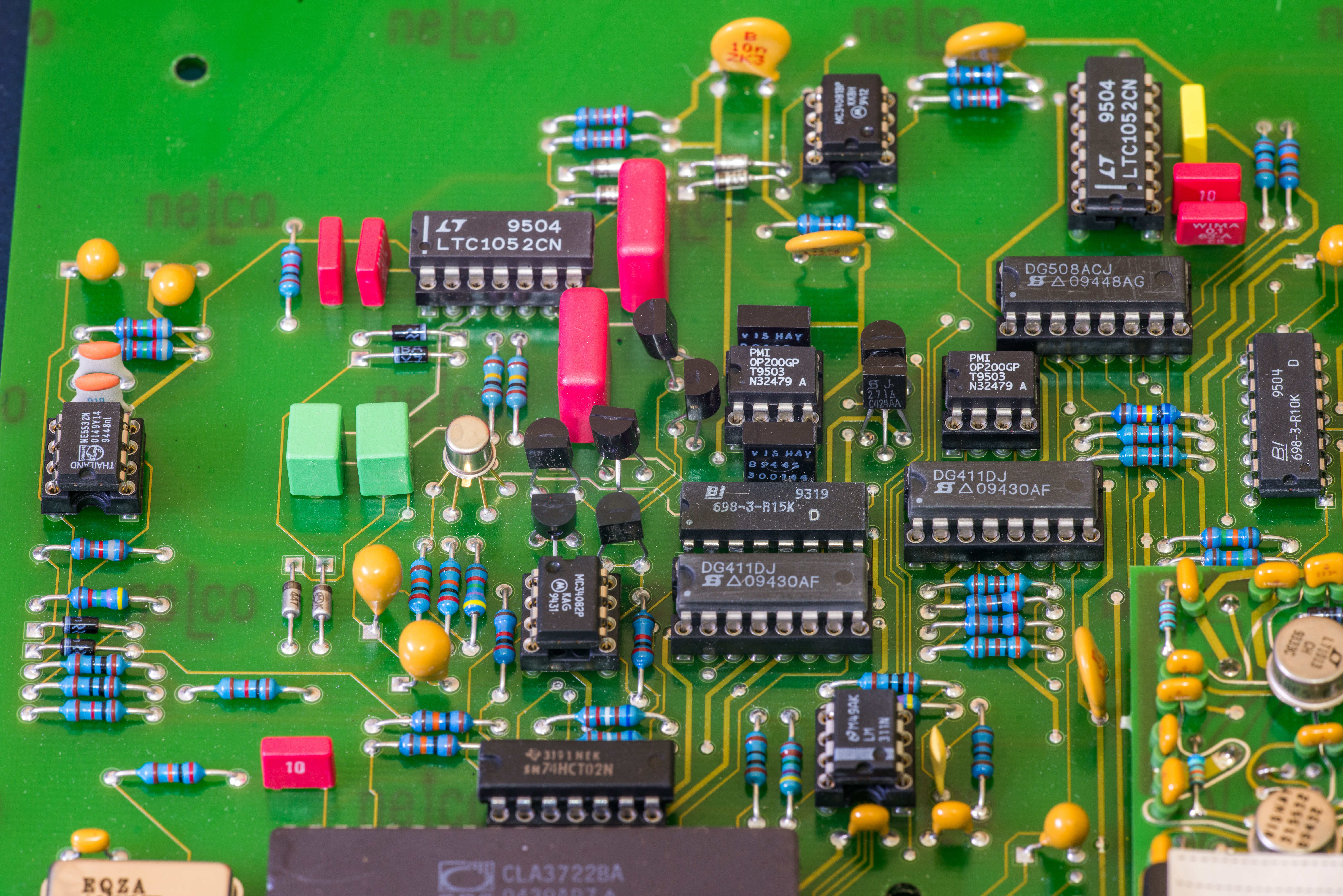
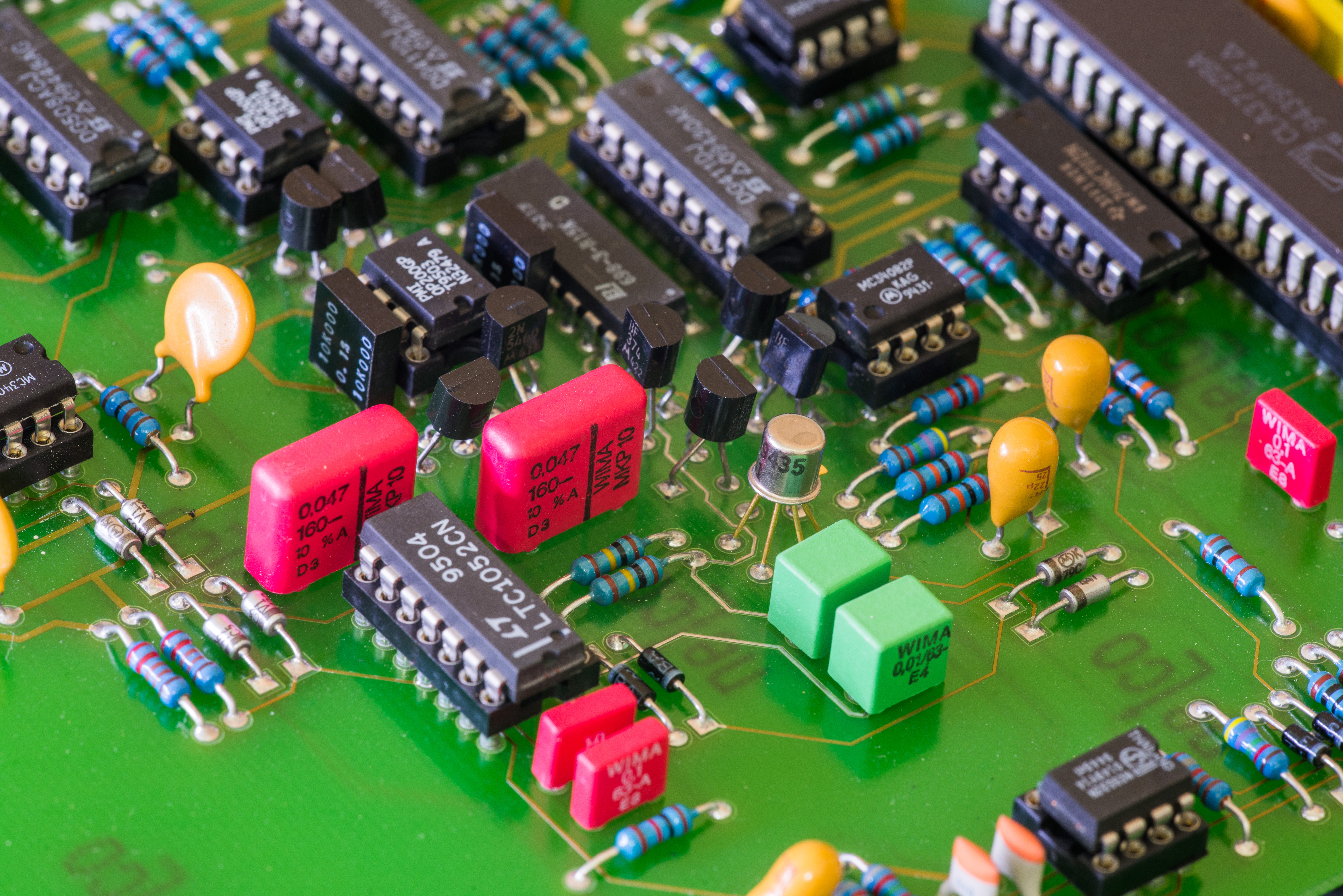
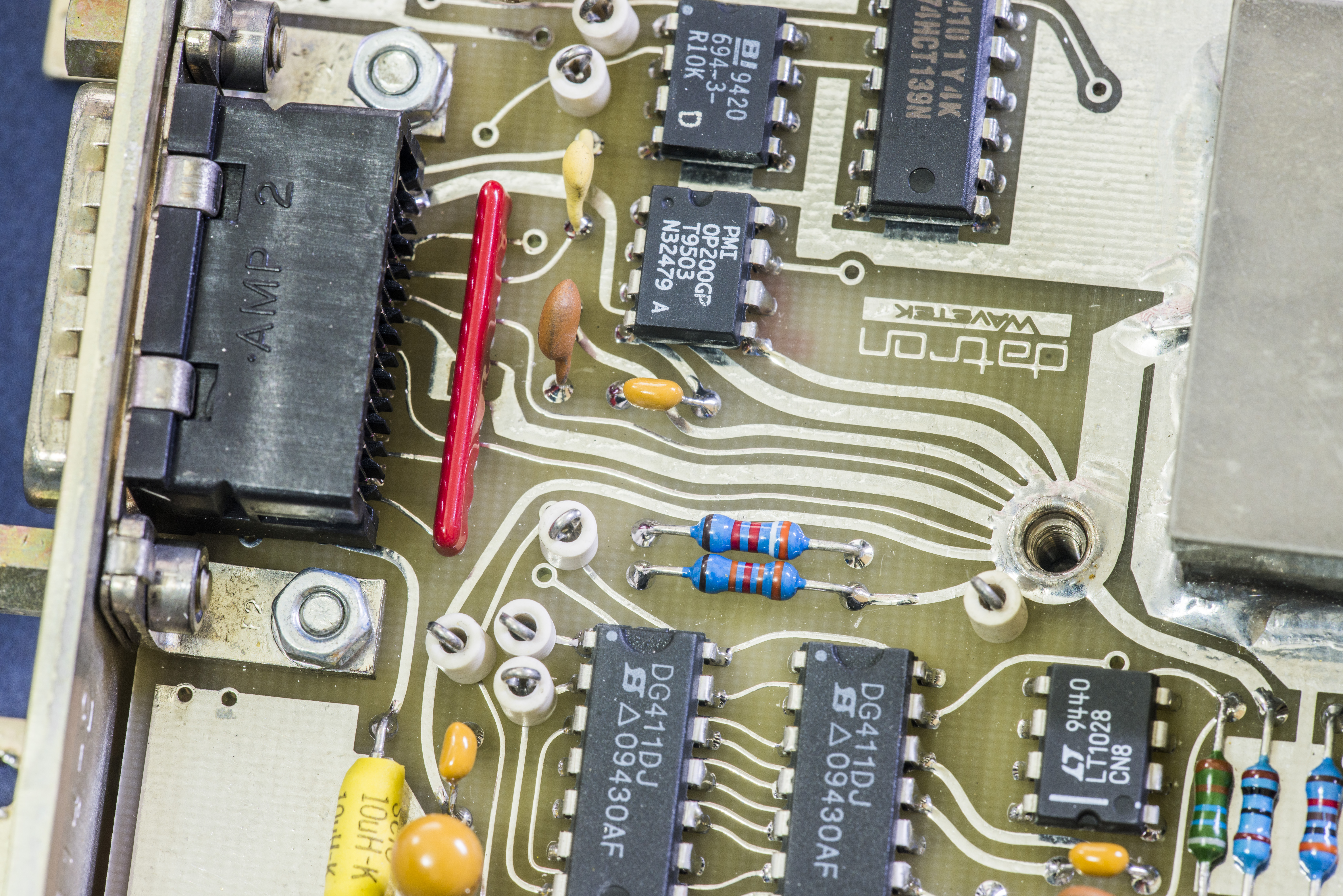
Output of this main reference is scaled using U406 MC34082 dual JFET op-amp with resistor network Beckman 698-3-R10KD (R415). Also with help of few low-offset/low-bias current Analog Devices OP200 opamp and JFETs reference currents are generated.

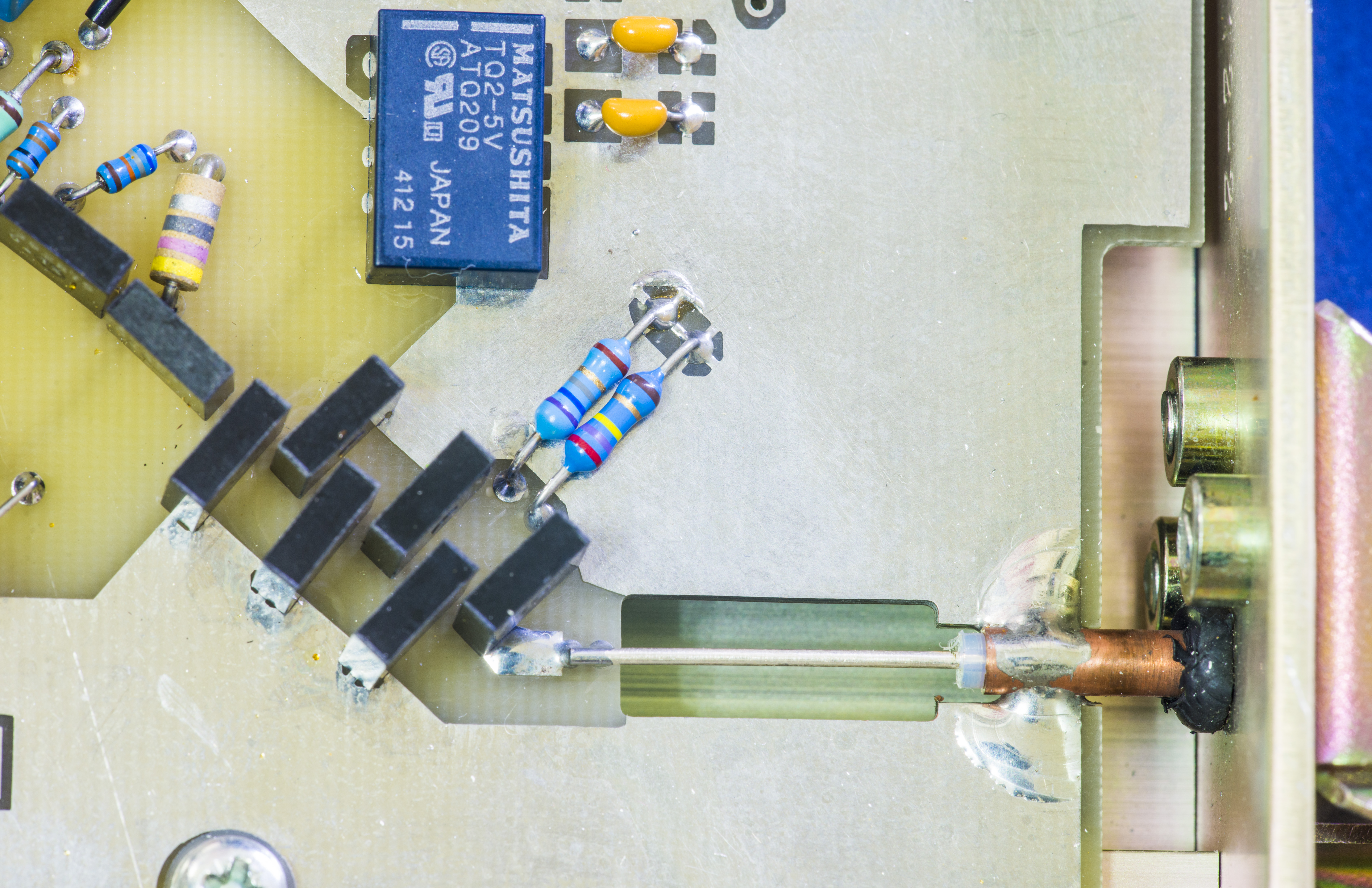
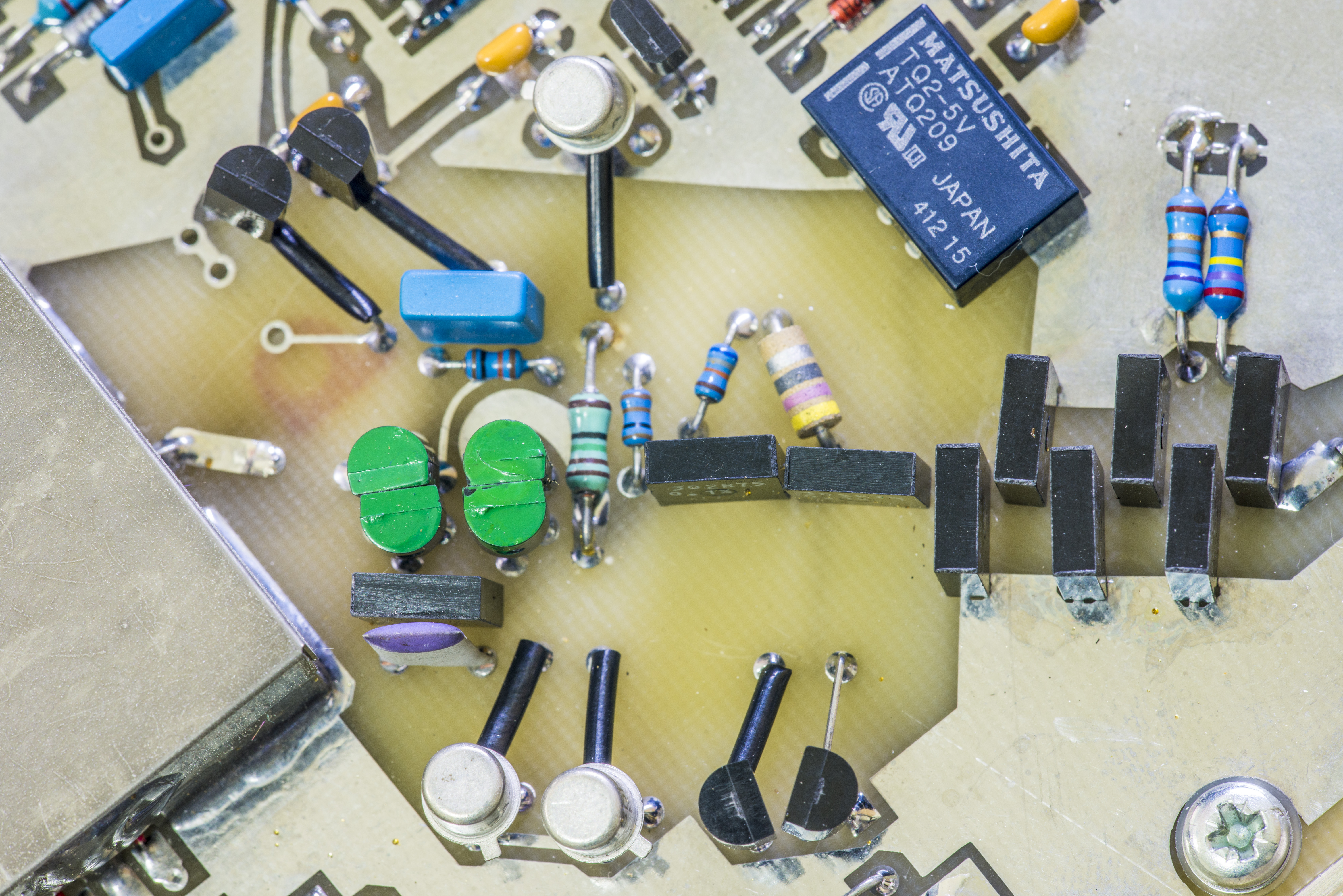
Image 5: Main DC reference, aux reference (violet block), output amp (orange), current generator (green)
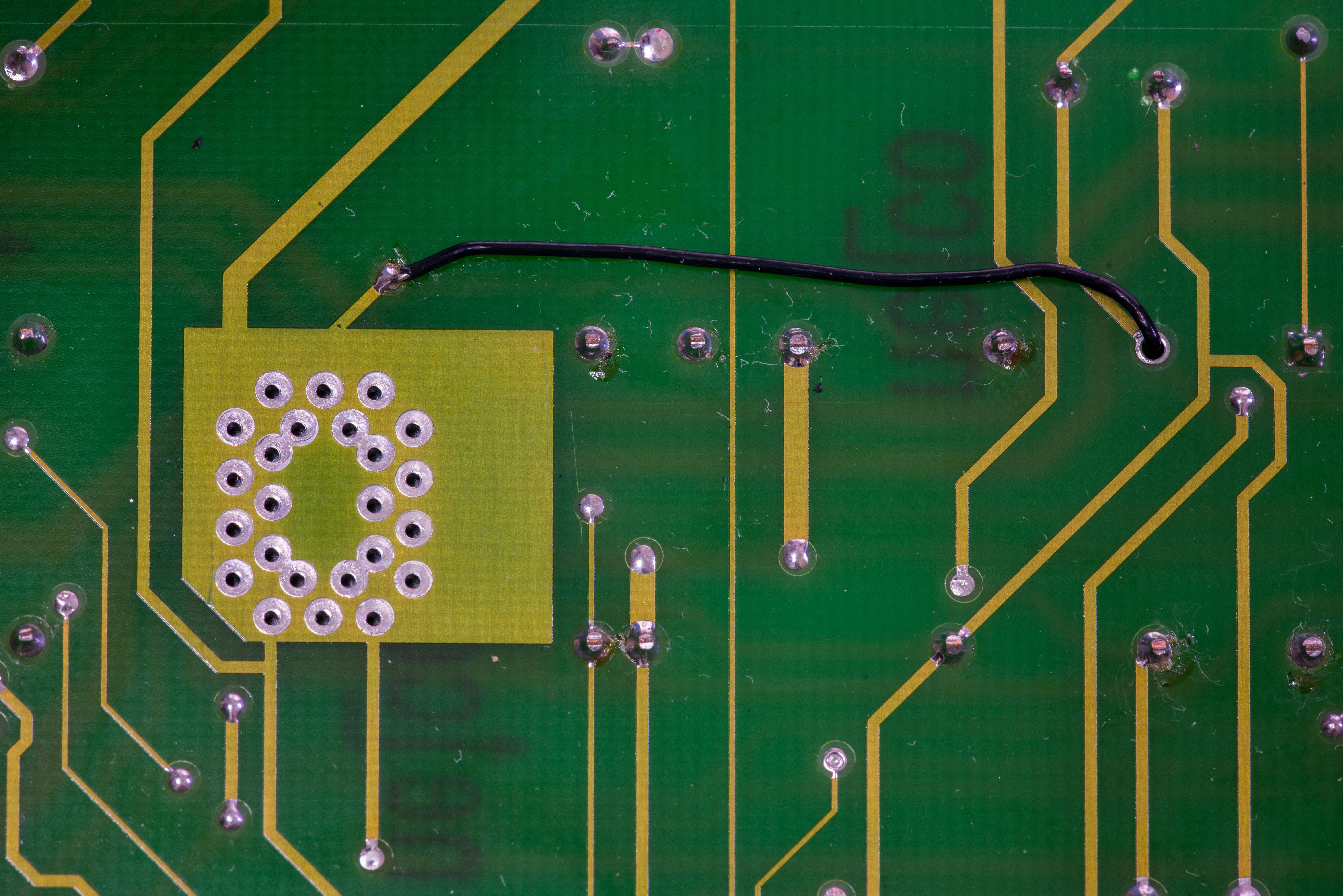
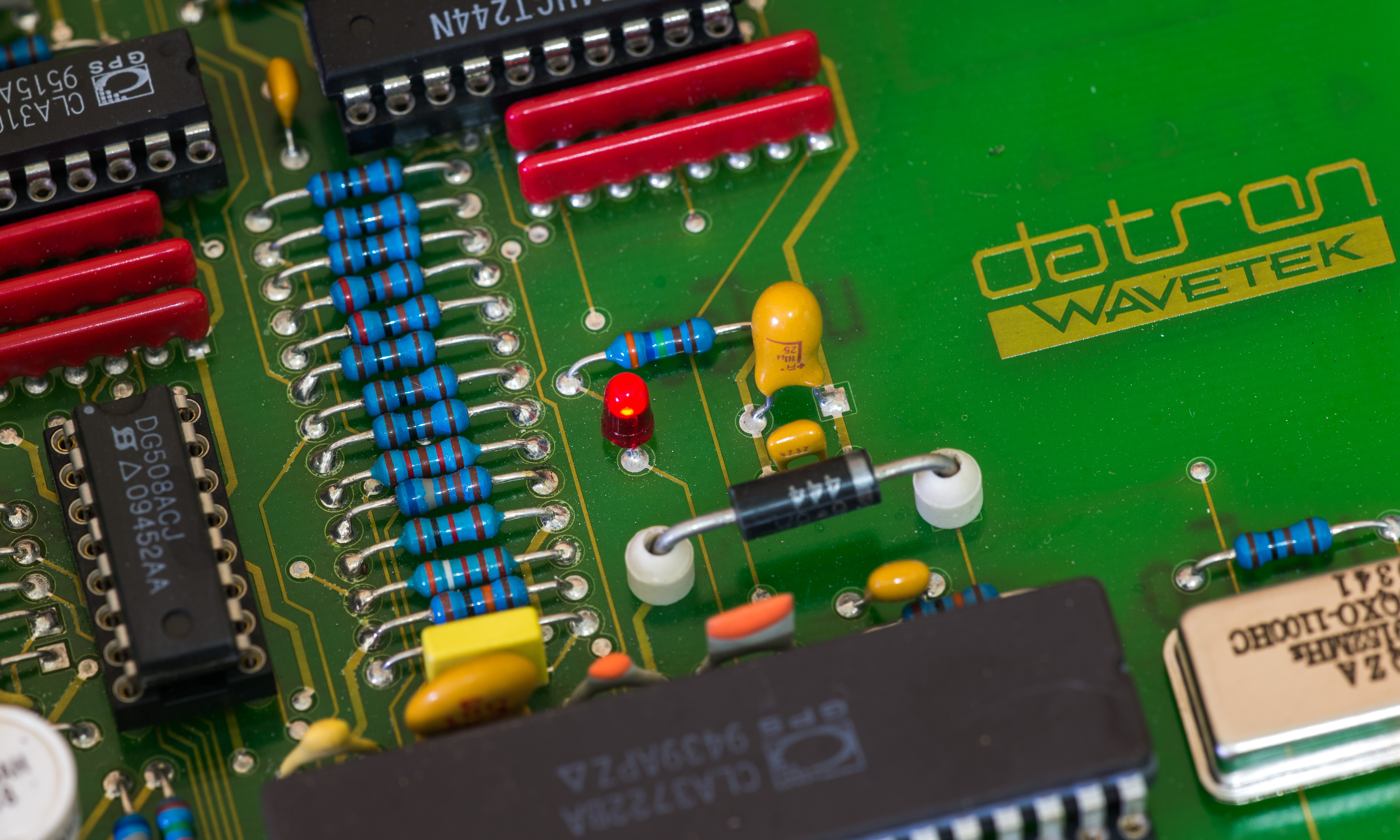
Another ovenized stable reference, using Linear LM399 is located nearby for self-test procedures purpose. For better understanding, stability of this reference is often good enough for most of commercial precision bench-top multimeters, like 6½-digit “Keithley 2000”/fix/kei2000, Agilent/Keysight 34465A, Fluke 8846A and even 7½-digit Keithley 2001! Signal output from reference is buffered via chopper amp Linear LTC1052 and provided to measurement path during self-tests. Grounded pad right under LTZ module aided for shielding reference from EMI.
Main ADC is expected multi-slope integration type, using discrete components and custom CLA3722 gate array logic from Zarlink Semiconductor for control and timing. Integrator is based around U505 NE5532 with LM311N null detector and U506 LTC1052 bias. Integrating capacitor consist of pair C504/C505, which are 10nF 63V 5% WIMA FKP2 polypropylene film capacitors with very low dielectric absorption and dissipation factor.
Together with ultra-stable reference, this A/D converter specified with 0.2 ppm full-scale linearity and less than 0.05 ppm full scale noise. Integration time is fixed 200ms to provide best rejection ratio at 60Hz and 50Hz mains.
Current switching for slopes done via DG411 solid-state mux (U502,U501) and Beckman 698-3-R15KD resistor network R416 (15KΩ 0.5%) with TCR <± 25 ppm/°C. Half of this resistor network already used in current generation circuit at DC reference section. This is done to ensure small relative drift of reference currents in ADC.
Analog Devices AD7545 is 12-bit MDAC with parallel bus interface. It has low gain temperature coefficient (10ppm/°C MAX) and around 2µs of output settling speed. It’s used for WB input characterization and self-calibration.

Capacitors were replaced with new long life Vishay and Chemi-Con ones.

Test measurement resulted good power regulator output:
| Voltage rail | Measured | Condition |
|---|---|---|
| +15V | +15.20 VDC | Good in spec |
| +5V | +5.019 VDC | Good in spec |
| -15V | -15.17 VDC | Good in spec |
| -19V | -18.57 VDC | Good in spec |
| +11V | +10.30 VDC | Good in spec |
There is also lonely red LED blinking in triple pulses during normal operation.
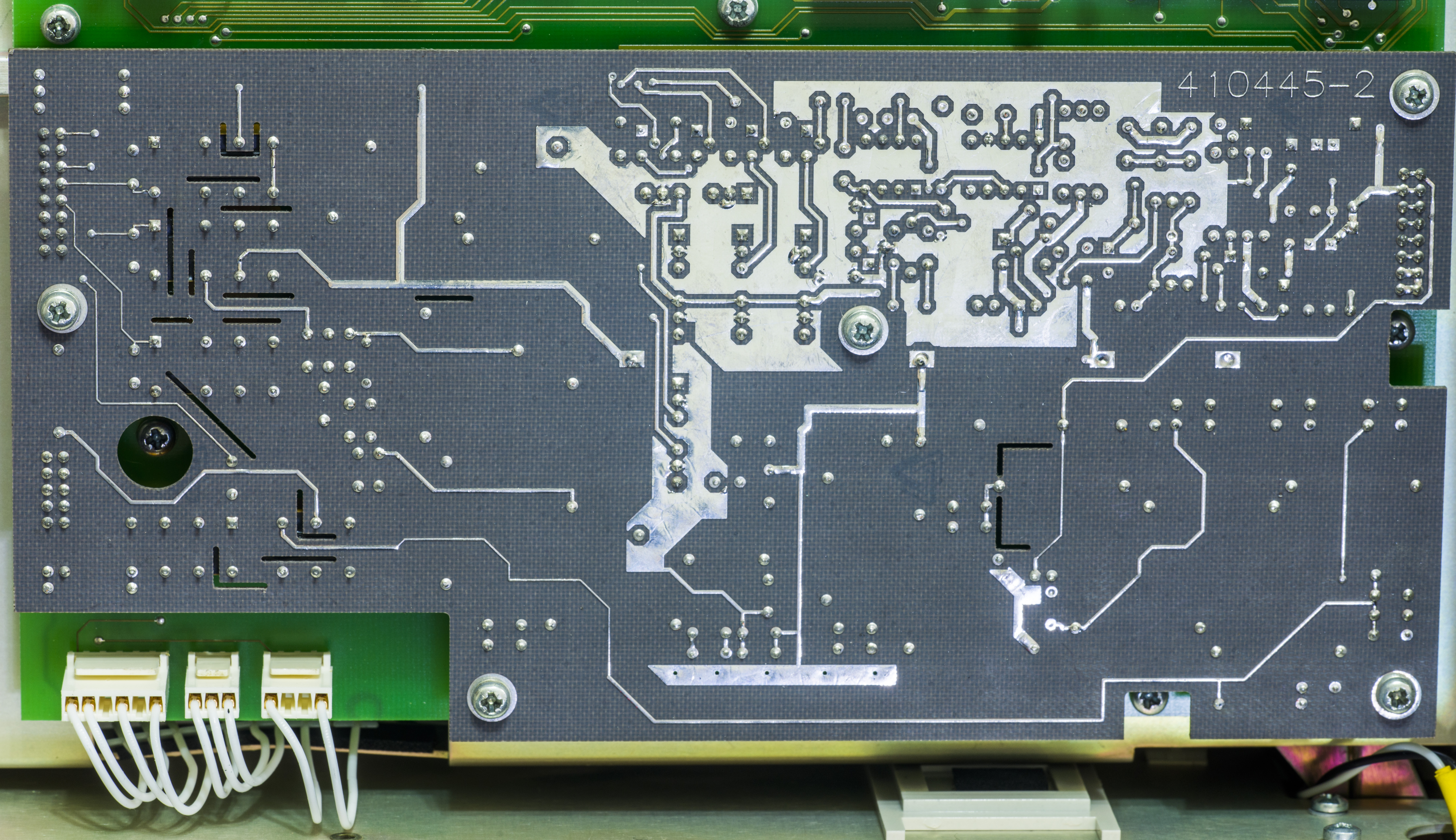
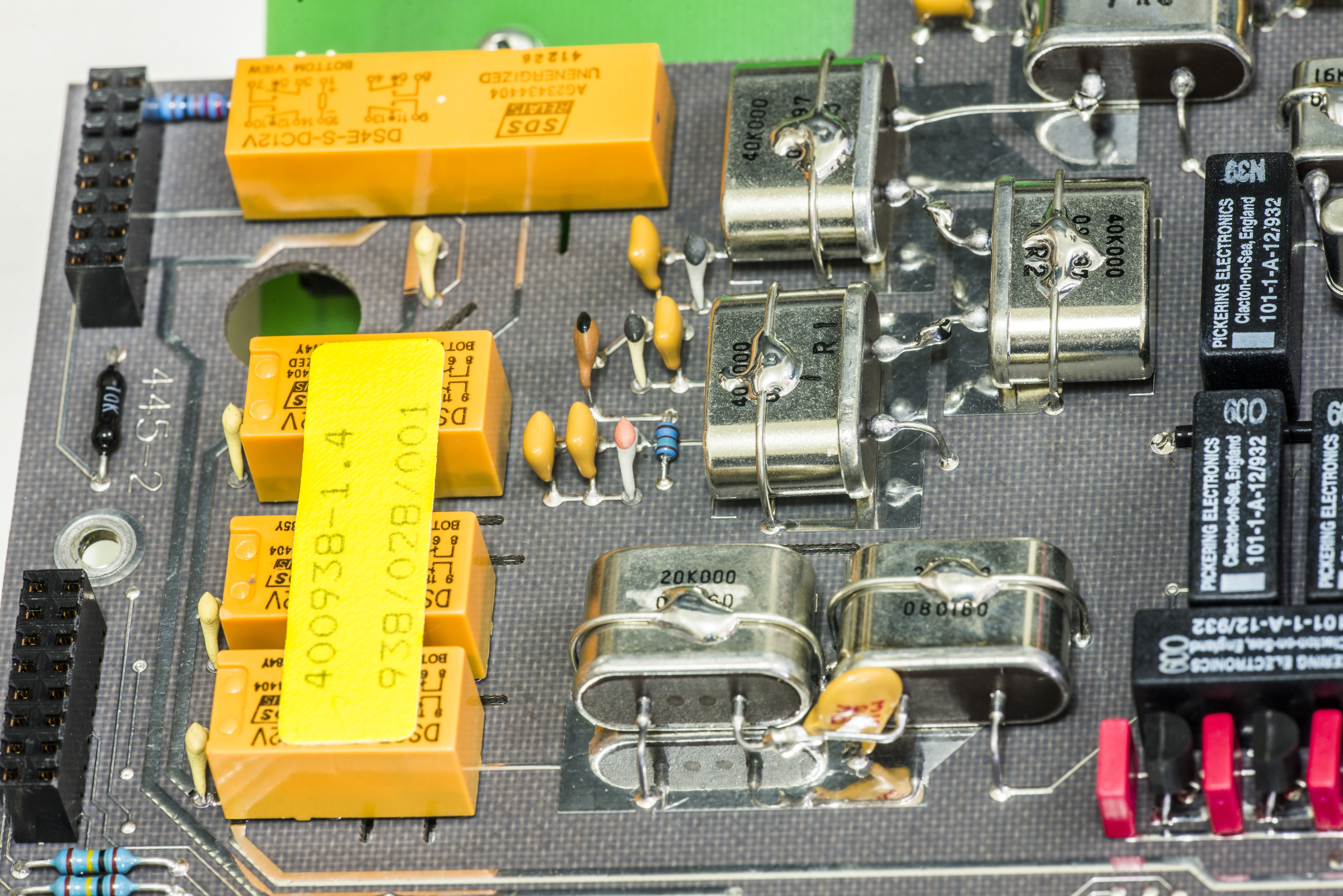
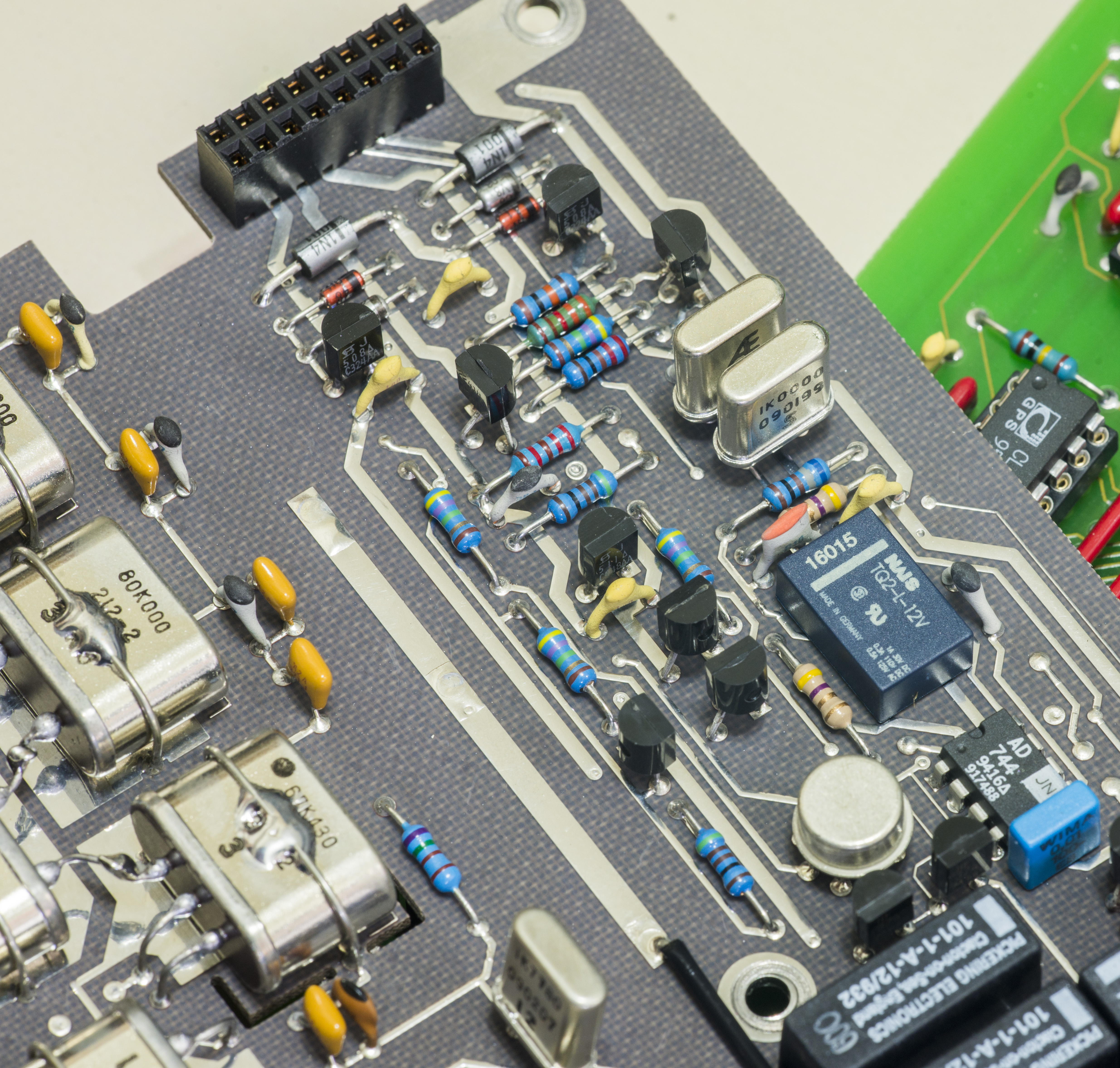
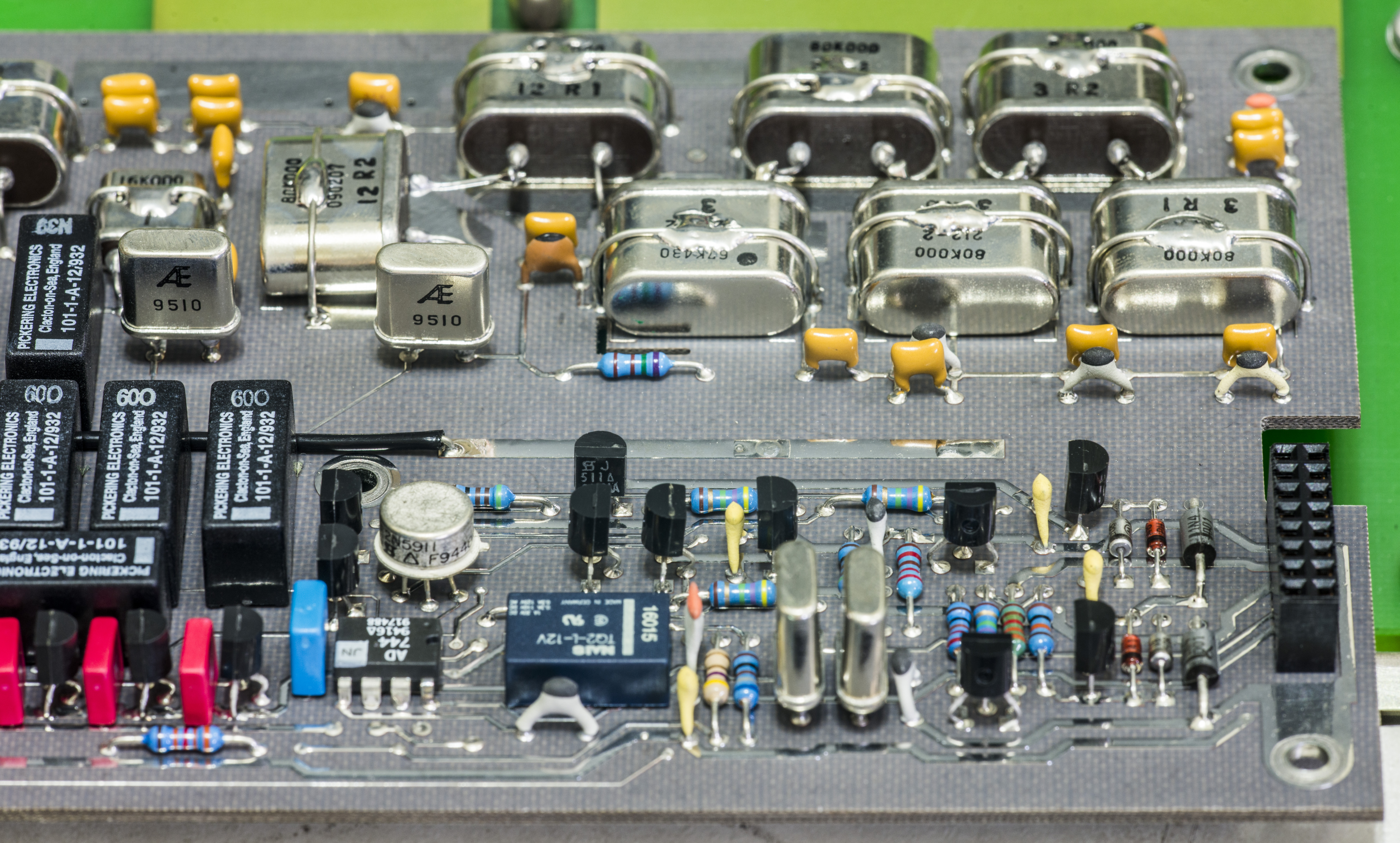
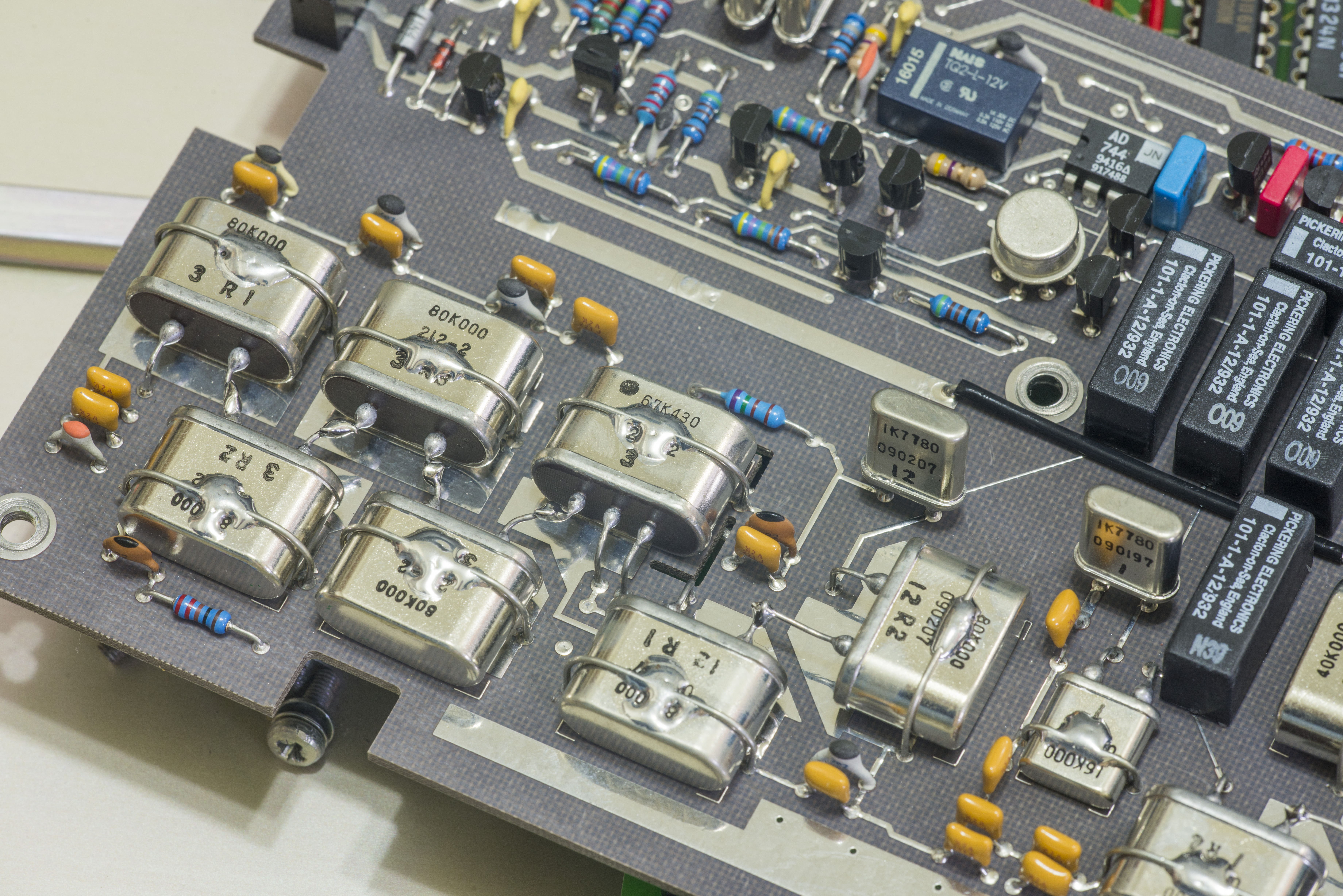
AC Preamp and attenuator PCBA – 400938
First thing to notice – unusual PCB color without any solder mask. Well, it’s because special material on this double-sided board, which is glass-reinforced Teflon (PTFE). This PCB material often used for tightly impedance controlled RF/microwave designs and applications. PTFE material provides superior dielectric properties, such as extremely low loss tangent, dielectric constant and high insulation resistance. Also PTFE board does not absorb moisture which improves environmental stability of high-frequency circuit. These benefits does not come free, and manufacturing, drilling and process control of such PCB material is difficult and expensive.
One may think that 4920M AC signal frequency range is only 1-20 MHz, which is not considered as RF by most of engineers. But if we remember about level of resolution this instrument provides, it become clear that very stable design has to be used to ensure specified accuracy and resolution down to microvolts. What’s good in 10 ppm measurement, if input signal actually affected by measurement circuitry more than this just in few minutes?
Now, following proper handling procedures and caution with clean gloves, let’s remove screws and check what we have on component side.
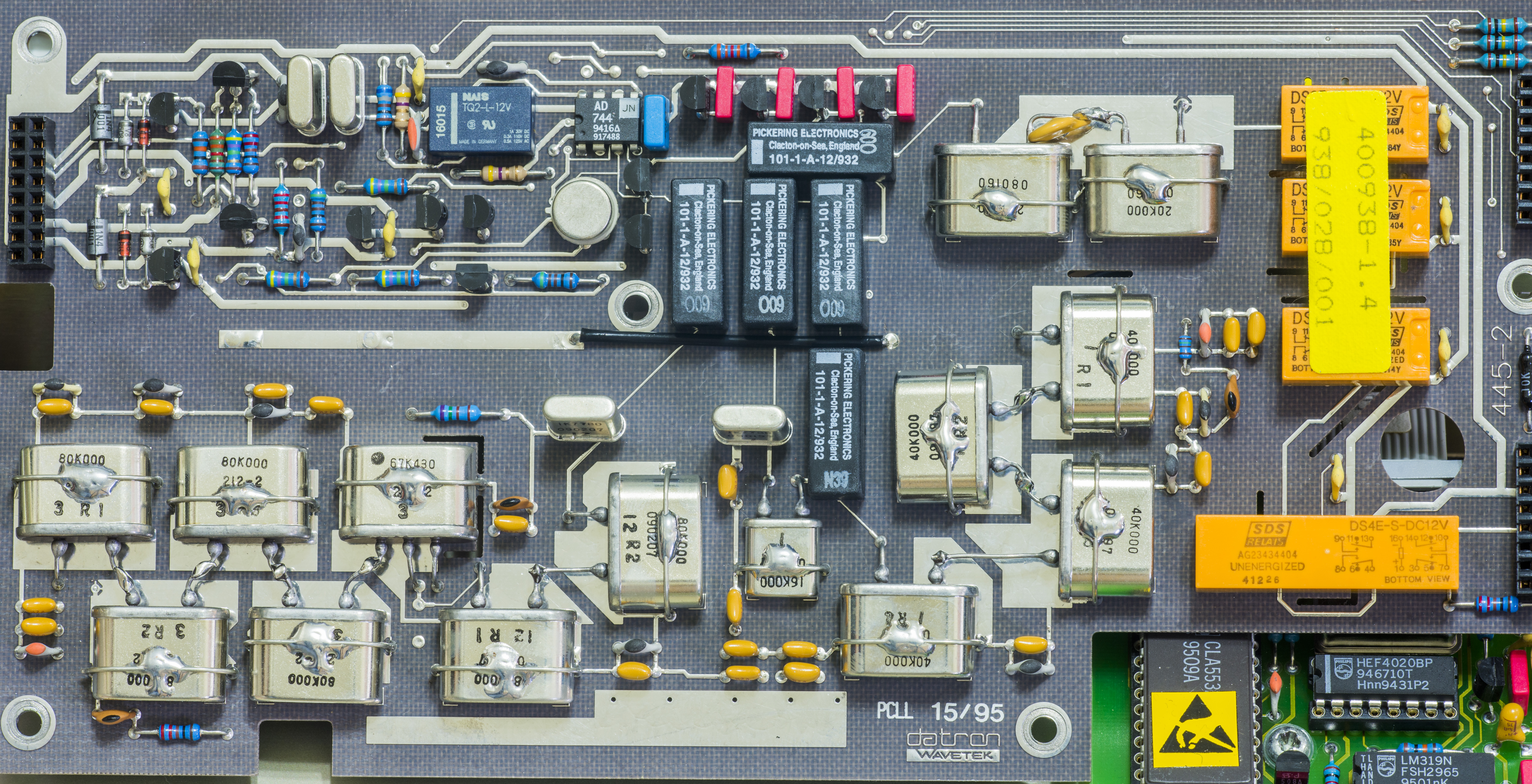
Constellation of unusually big precision hermetic foil resistors, manufactured by Alpha Electronics (today part of Vishay Precision Group), with some smart design. Surely some Datron’s analog gray beard guru’s were working on these in utopia land. ;)

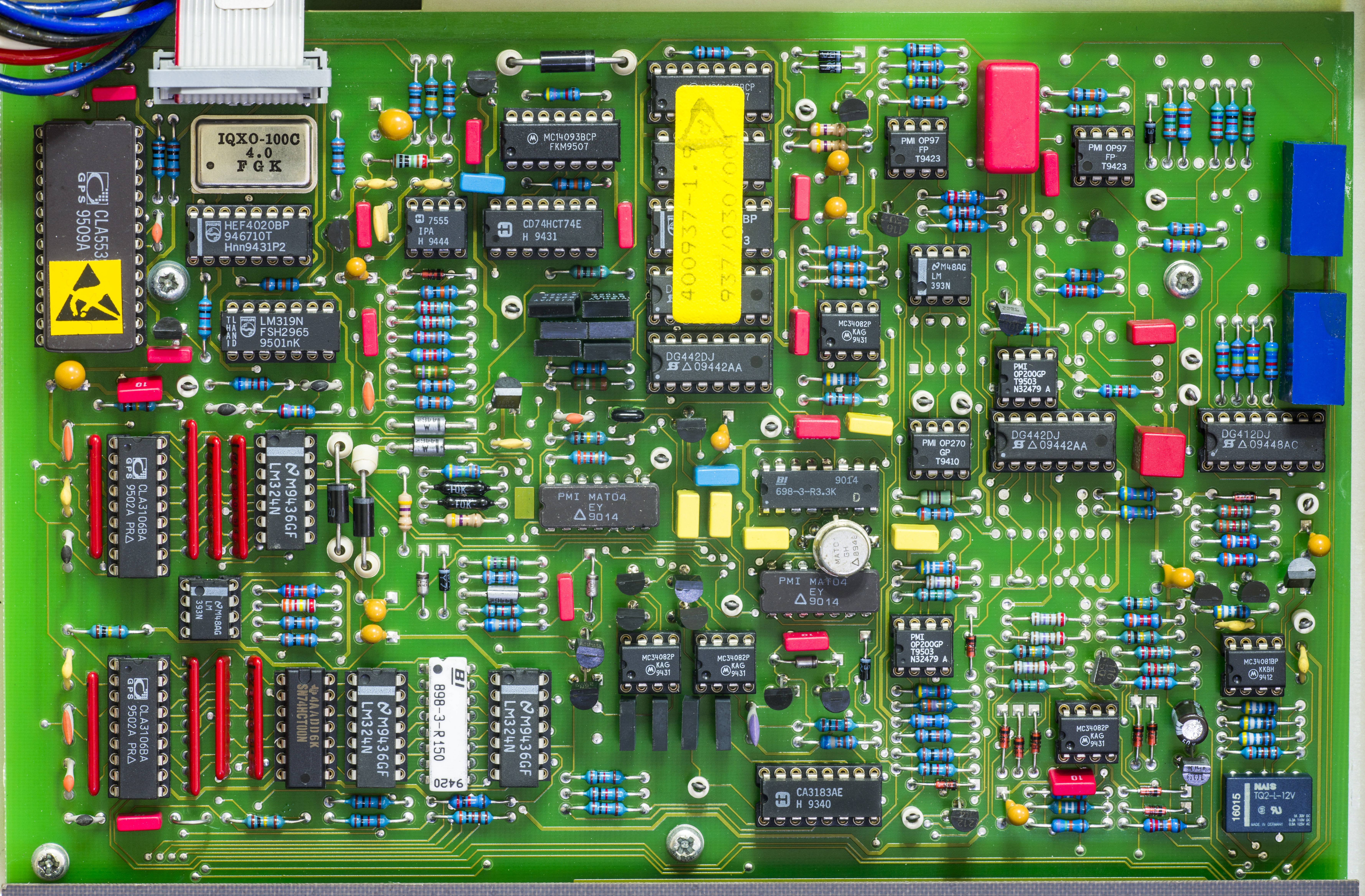
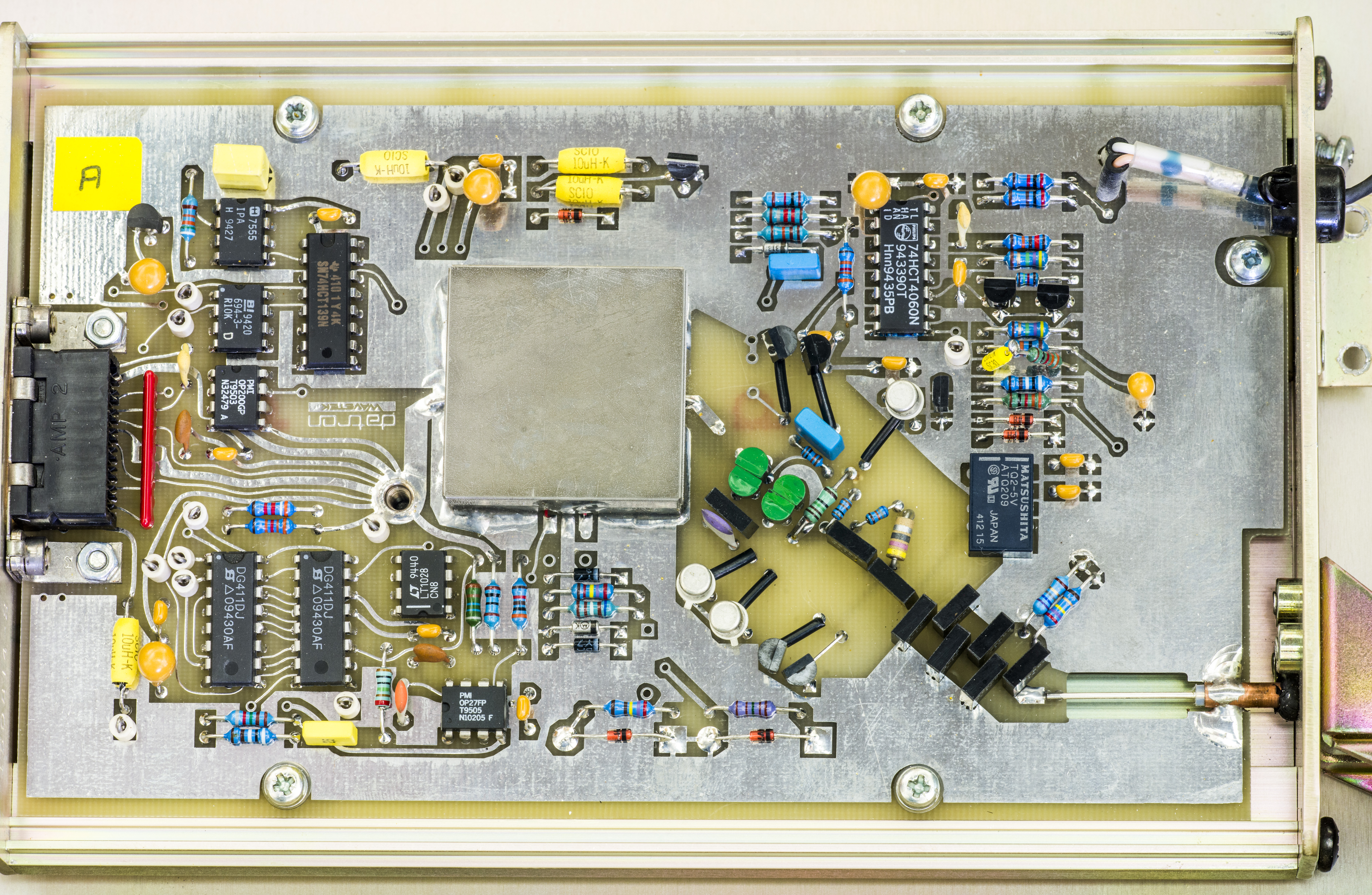
High accuracy ACV PCBA – 400937

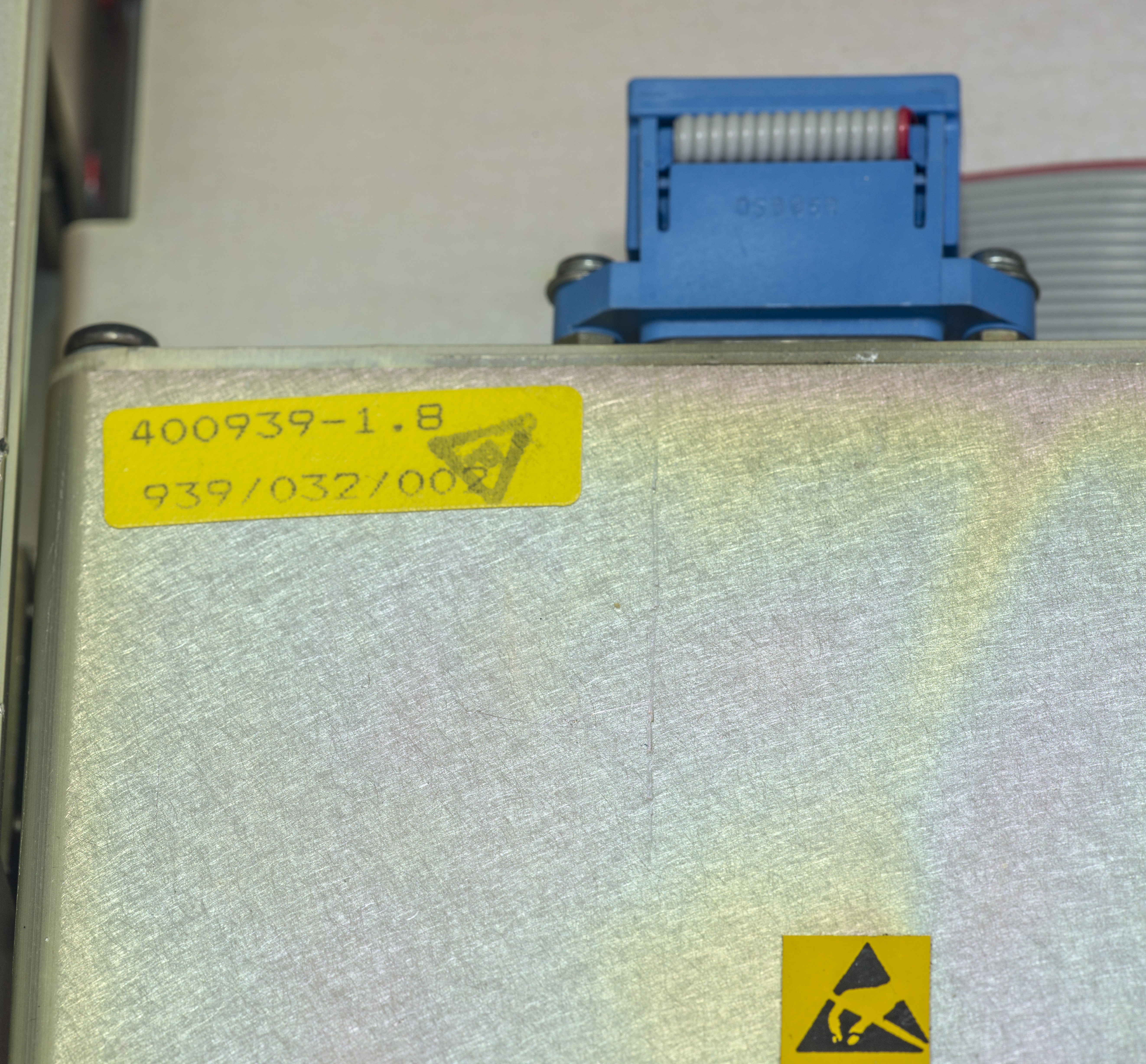
Wideband AC PCBA module – 400939
Highest accuracy AC-DC transfers are realized by the use of “thermal converters”. What is thermal converter, you may ask? Single-Junction thermal converters (SJTC) were developed around 1950. The structure of a typical SJTC element is shown on image below.
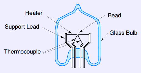
Image X: Typical TVC construction, courtesy of AIST, Japan .
Very fine wire, forming filament/heater and a precision thermocouple are sealed in vacuum glass bulb. The thermocouple junction directly attached with the heater at midpoint. Thermocouple and heater are electrically insulated by a bead of glass or ceramic dielectric. Best thermal converters are capable of comparing the joule heating between AC and DC signals down at 0.1 ppm level precision, and is widely employed as the primary standard in most national standard laboratories even today. There are more accurate options exist today, such as AC Quantum array using Josephson effect but these are limited to less than few MHz frequency bandwidths.
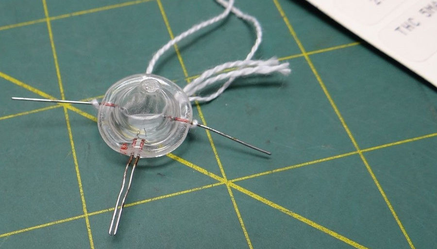
Image X: Single-junction 5mA TVC from Ballatine
However modern ACV metrology equipment like AC/DC Transfer Standard Fluke 792A or AVMS Fluke 5790A or 5790B feature specially designed semiconductor thermal transfer sensor elements using modern materials. Perhaps part of reason for it due to fragility of TVC’s, which cannot tolerate even minimal overload conditions.
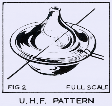
Image X: Best Technology UHF TVC construction
Datron/Wavetek 4920M wideband module is using single-junction TVC. It’s manufactured by US company Best Technology which is still around, and has insulated UHF-type hermetic thermal converter used here. Same Evanohm metal used for heater wire and thermocouple junction leads to ensure sub-ppm errors from Seebeck and Peltier effects. Manufacturer’s catalog lists variety of TVC models. One used in 4920M is listed as insulated 5.0mA type, S.7 type, as TVC DC output amplifier is configured to provide signal gain of 867 (1 mV output from TVC will be amplified into 867 mV) by U205 Linear LT1028CN8 ultra-low noise amplifier. Gain is set by fixed 8.66 kΩ and 10 Ω R203/R204 resistors. Higher voltages, like 10mV would cause opamp to saturate due to its +11VDC and -19VDC power supply.


Firmware
Firmware is stored in JEDEC-standard compatible 1Mbit ROM chips, such as HN27C101A
| Firmware version | ROM1 U103, Part 1A | ROM2 U104, Part 1B | Combined, LE |
|---|---|---|---|
| Model 4920M, Version 1.00, Date 12-07-1990 | 4920M 40093S A | 4920M 40093S B | Combined |
| Model 4920M, Version 1.01, Date 22-04-1992 | 4920M 40093S A | 4920M 40093S B | Combined |
For version 1.00 and 1.01 credits go to Pipelie at EEVBlog forum.
To peek thru firmware, combined image was generated using simple Python snippet:
# xDevs.com Firmware combine tool
# https://xdevs.com/fix/d4920m/

import os

print "Combine tool for 2 FW ROMs into 1 256KB ROM, for Wavetek 4920M"
with open('4920M-40093S-1.0A-12.7.90.BIN','rb') as b:
    with open('4920M-40093S-1.0B-12.7.90.BIN','rb') as a:
        with open('w4920-1_0_12_07_1990.BIN','wb') as x:
            for cnt in range(0, 65536):
                x.write ("%c" % a.read(1) )
                x.write ("%c" % b.read(1) )
                x.write ("%c" % a.read(1) )
                x.write ("%c" % b.read(1) )
If you have firmware for 4920M or any other instrument, please contact us for upload.
Calibration
5720A + 5790A + swerlein 3458A
Remote control examples
This instrument has only IEEE-488 GPIB interface. Interfacing was straight forward with our existing setup on Raspberry Pi with NI GPIB-USB-HS and linux-gpib library.
Standard identification [*IDN?] worked just fine with result below.
'Wavetek-Datron,4920M,29336 ,400935-01.01'
Quick calibration data check revealed that almost all constants are reset to default. This confirms initial catch with invalid readings on various ranges.
DUMP? Range 10.0 V, 0 = 001,+0.3000000E+01,+0.3000000E+01
DUMP? Range 10.0 V, 1 = 002,+1.0000000E+01,+1.0000000E+01
DUMP? Range 10.0 V, 2 = 003,+0.0000000E-40,+0.0000000E-40
DUMP? Range 10.0 V, 3 = 004,+0.5000068E+05,+0.8776189E-01
DUMP? Range 10.0 V, 4 = 005,+0.2000027E+06,+0.8704789E-01
DUMP? Range 10.0 V, 5 = 006,+0.5000067E+06,+0.8533230E-01
DUMP? Range 10.0 V, 6 = 007,+1.0000137E+06,+0.8916546E-01
DUMP? Range 10.0 V, 7 = 008,+0.0000000E+00,+0.0000000E+00
DUMP? Range 10.0 V, 8 = 009,+1.0000001E+00,+1.0818163E+00
DUMP? Range 10.0 V, 9 = 010,+0.9765597E+00,+0.0000048E+00
To generate DUMP output I used simple python app:
# xDevs.com Python app to DUMP cal data from 4920M
# http://xdevs.com/fix/d4920m
import sys
import Gpib

inst = Gpib.Gpib(0,2) # 4920M
inst.clear()
selacv = [0.3, 1.0, 3.0, 10.0, 30.0, 100.0, 300.0, 1000.0]

with open ("dump_w4920_precal.log", 'w') as log:
    inst.write("*IDN?")
    str = inst.read(240)
    print str
    log.write ("ID = %s" % str)
    for rng in range (0, 8):
    inst.write("ACV %4.2f,RESL7" % selacv[rng])
        for cnt in range (0, 10):
            inst.write("DUMP?")
            str = inst.read(500)
            log.write ("DUMP? Range %.1f V, %d = %s" % (selacv[rng], cnt, str))
            print ("DUMP? Range %.1f V, %d = %s" % (selacv[rng], cnt, str))
log.close()
Interfacing instrument via remote commands is simple.
Restoration summary
| Item | Cost | Shipping | Supplier |
|---|---|---|---|
| Unknown condition Wavetek 4920M | 625$ | 98$ | eBay |
| DigiKey components order | 100$ | N/A | DigiKey.com USA |
Table 20: Project cost
Also some generic parts were ordered from DigiKey store, such as mains filter jack, capacitors. Here’s DigiKey.com order list:
| Quantity | Part Number | Description | Extended Price USD |
|---|---|---|---|
| 4 | 565-1846-ND | CAP ALUM 1000UF 20% 50V RADIAL (KME) | 2.46 |
| 25 | 565-1546-ND | CAP ALUM 1UF 20% 100V RADIAL | 2.85 |
| 25 | 565-1546-ND | CAP ALUM 220UF 20% 63V RADIAL | 2.85 |
| 25 | 565-1546-ND | CAP ALUM 10UF 20% 50V RADIAL | 2.85 |
| 25 | 565-1546-ND | CAP ALUM 220UF 20% 100V RADIAL | 2.85 |
| 25 | 565-1546-ND | CAP ALUM 220UF 20% 50V RADIAL | 2.85 |
| 25 | 565-1546-ND | CAP ALUM 470UF 20% 25V RADIAL KMC | 2.85 |
| 25 | 565-1546-ND | CAP ALUM 10UF 20% 50V RADIAL | 2.85 |
| 25 | 565-1546-ND | CAP ALUM 10UF 20% 25V RADIAL tantalum | 2.85 |
| 25 | 565-1546-ND | CAP ALUM 22UF 20% 25V RADIAL tantalum | 2.85 |
| 1 | 603-1155-ND | FILTER IEC CONNECTOR 115/250VAC | 6.61 |
Table 22: Time work log summary
Total man-hours spent on this project around 15 hours, give or take few. Was it worth doing? That’s up to you, so please leave your comments, so I can do more stuff like this.
Other related documents
Thanks for reading. Hope you like the article, and if you do have any questions, jump in comments!
Projects like this are born from passion and a desire to share how things work. Education is the foundation of a healthy society - especially important in today's volatile world. xDevs began as a personal project notepad in Kherson, Ukraine back in 2008 and has grown with support of passionate readers just like you. There are no (and never will be) any ads, sponsors or shareholders behind xDevs.com, just a commitment to inspire and help learning. If you are in a position to help others like us, please consider supporting xDevs.com’s home-country Ukraine in its defense of freedom to speak, freedom to live in peace and freedom to choose their way. You can use official site to support Ukraine – United24 or Help99. Every cent counts.
Modified: Aug. 28, 2021, 4 a.m.