Contents
- Intro
- Disclaimer
- Initial inspection and basic disassembly
- Manuals references
- Repair workflow
- Diagnostics
- Firmware
- Tweaks
- Calibration
- Performance verification
- Residual weak signals verification in DCV HIRES, 0 VDC source mode
- Restoration summary
Intro
For those, who may thought repairing 3458A was not enough, here’s another, way less known, piece of gear from 90’s – HP 3245A Universal source. This unit is already discontinued long ago (if you know when – please let me know, I’ll update article accordingly) and currently covered only by Extended service period program from Keysight, which started from 7/1/2005. There is very scarce information available on web about this universal source, so it will be interesting to see what makes it ticking.
My specific 3245A-002 was purchased as “parts, non-functional” piece for $340 USD. Unit did power on, but was throwing self-test errors. Seller also mentions that unit could work, if errors are cleared manually. Well, will see how serious the problem is. Used units in good condition, are going for around 1000$ on secondary market, so it is expensive, but obtainable unit for serious hobbyists. I did notice these universal sources before, but their rather limited output voltage range did not interest me much. This time, unit equipped with high-voltage 002 option, which is basically power amplifier with 10x gain, so I could use this meter as DC/AC calibration source for general purposes. That would be possible in case of successful repair, of course.
As usual, all photos are clickable for high-resolution version.
There are also option versions of 3245A per HP Catalog from 1993, such as:
| Unit P/N | Function | Extra cost over base |
|---|---|---|
| 3245A-001 | Second channel option | $2750 USD |
| 3245A-002 | High-Voltage Amplifier | $1530 USD |
Only one option can be chosen, as these options are using different hardware boards and cannot be installed together.
Modern replacement product for 3245A suggested by Keysight is B2961A 6½-decade low noise SMU. But it’s not quite fully equal replacement, since 3245A provides far wider AC frequency coverage then B2961A SMU, so it’s still not same kind of instrument
Key specs for comparison listed below, also together with popular Keithley 2400 SMU which I also own.
| Feature | HP 3245A | Keysight B2961A SMU | Keithley 2400 SMU |
|---|---|---|---|
| DCV output range | 78.125mV to 10V (100V for Opt.002) or 1V/10V in HiRes mode | 4 ranges, 200mV to 200 V | 4 ranges, 200mV to 200V |
| DCV output power | 1W | 31.8W | 22W |
| DCV polarity | 4-quadrant | 4-quadrant | 4-quadrant |
| DCV accuracy, best | ±0.00071% + 85µV | ±0.015% + 225µV | ±0.020% + 600µV |
| DCI output range | 4 ranges, 100µA,1mA,10mA,100mA | 12 ranges, 10nA to 10A | 7 ranges, 1µA to 1A |
| DCI accuracy, best | ±0.0072% + 3.9nA | ±0.020% + 25nA | ±0.031% + 20nA |
| AC frequency range | DC to 1MHz for sine,ARB,square or 100kHz for ramp | DC to 10kHz | DC to 10kHz |
| Source resolution | 6½ digits | ||
| DCV noise | 2mVpp or .6mVrms up to 250kHz | <5µVpp 0.1-10Hz, 3mVrms 10-20MHz | 5µVpp 0.1-10Hz |
| DC measurement | None | 4½ digits | 5½ digits |
| Voltage reference | LM399 | ? | Zener |
| MSRP | $4650 USD | $6268 USD | $4830 USD |
Disclaimer
Redistribution and use of this article or any images or files referenced in it, in source and binary forms, with or without modification, are permitted provided that the following conditions are met:
- Redistributions of article must retain the above copyright notice, this list of conditions, link to this page (/fix/hp3245a/) and the following disclaimer.
- Redistributions of files in binary form must reproduce the above copyright notice, this list of conditions, link to this page (/fix/hp3245a/), and the following disclaimer in the documentation and/or other materials provided with the distribution, for example Readme file.
All information posted here is hosted just for education purposes and provided AS IS. In no event shall the author, xDevs.com site, or any other 3rd party, including HP/Agilent/Keysight be liable for any special, direct, indirect, or consequential damages or any damages whatsoever resulting from loss of use, data or profits, whether in an action of contract, negligence or other tortuous action, arising out of or in connection with the use or performance of information published here.
If you willing to contribute or add your experience regarding HP/Agilent/Keysight instruments repairs or provide extra information, you can do so following these simple instructions
Initial inspection and basic disassembly


Damaged parts (and current status):
- Error on power on Fixed, loose cable between boards
- Old electrolytic capacitors on A3 PCBs Replaced
- Old electrolytic capacitors on A6 PCBs Replaced
- Old electrolytic capacitors on A1 PCBs Left as is for now
- Prone to explosions Schaffner FN 323-3/05 EMI/mains filter Replaced
Manuals references
03245-90001 – Operation and programming manual, Edition 1, 1988
03245-90002 – Command reference, Edition 1, 1988
03245-90013 – Calibration Manual, Edition 2, 1991
03245-90015 – Repair manual, Edition 1, 1992
I also have bought electronic variant of HP CLIP for 3245A from Artek Manuals so we all can enjoy schematics and BOM. They have hundreds of greatly remastered manuals, so be sure to check their repository for other goodies.
03245-90033 – Component Level Information Packet with schematics
Repair workflow
As usual, we have project tracker, dedicated for 3245A repair so any one can track the progress.
Before starting any repair, good idea to read thru repair manuals, to get idea of board functions and purpose. Boards used in 3245A Universal source and their designators are:
| Ref Designator | HP Part Number | Assembly Description |
|---|---|---|
| A1 | 03245-66511 | InGuard Source PC Assembly, Rev.C |
| A1 (002) | 03245-66517 | InGuard Source PC Assembly, Option 002 |
| A2 | 03245-66502 | Backplane PCBA, Rev.C |
| A2 (002) | 03245-66516 | Backplane PCBA, Option 002 |
| A3 (002 only) | 03245-66503 | High-voltage amplifier, Option 002 only |
| A5 | 03245-66505 | Outguard Controller |
| A6 | 03245-66506 | Outguard power supply |
| A7 | 03458-66507 | Display logic |
Option 001 have two 03245-66511 boards, to feature second channel. That’s why you can only install either option 001, or high-voltage output 002, as both boards share only same slot.
No, it’s not a typo, A7 board is really identical to HP 3458A 8½-digit multimeter. Fan, steel chassis, outer covers, some cables are exactly same, used in both 3458A and 3245A.
I would expect A5 and A6 boards very close to ones used in 3458A as well, just with different BOM and firmware ROMs perhaps. So 3245A can be used as a donor for replacement of 3458A’s Outguard boards or chassis/front panel, as buying new front panel for 3458A with display cost over 850$USD, while broken 3245A could be easy less than that.
Some parts are listed as obsolete on Keysight Parts store, so it’s unlikely that you can buy anything for 3245A. List of parts and from Keysight, Excel table
HP/Agilent/Keysight does not support users doing component-level repairs, so asking them stuff like “I have problem A with my meter, found broken component R982 and U180, can you sell me new component?” would be overly optimistic.
Boards condition check
Worth to note first, that mains transformer used in HP 3245A Universal source is NOT the same one, as 3458A.
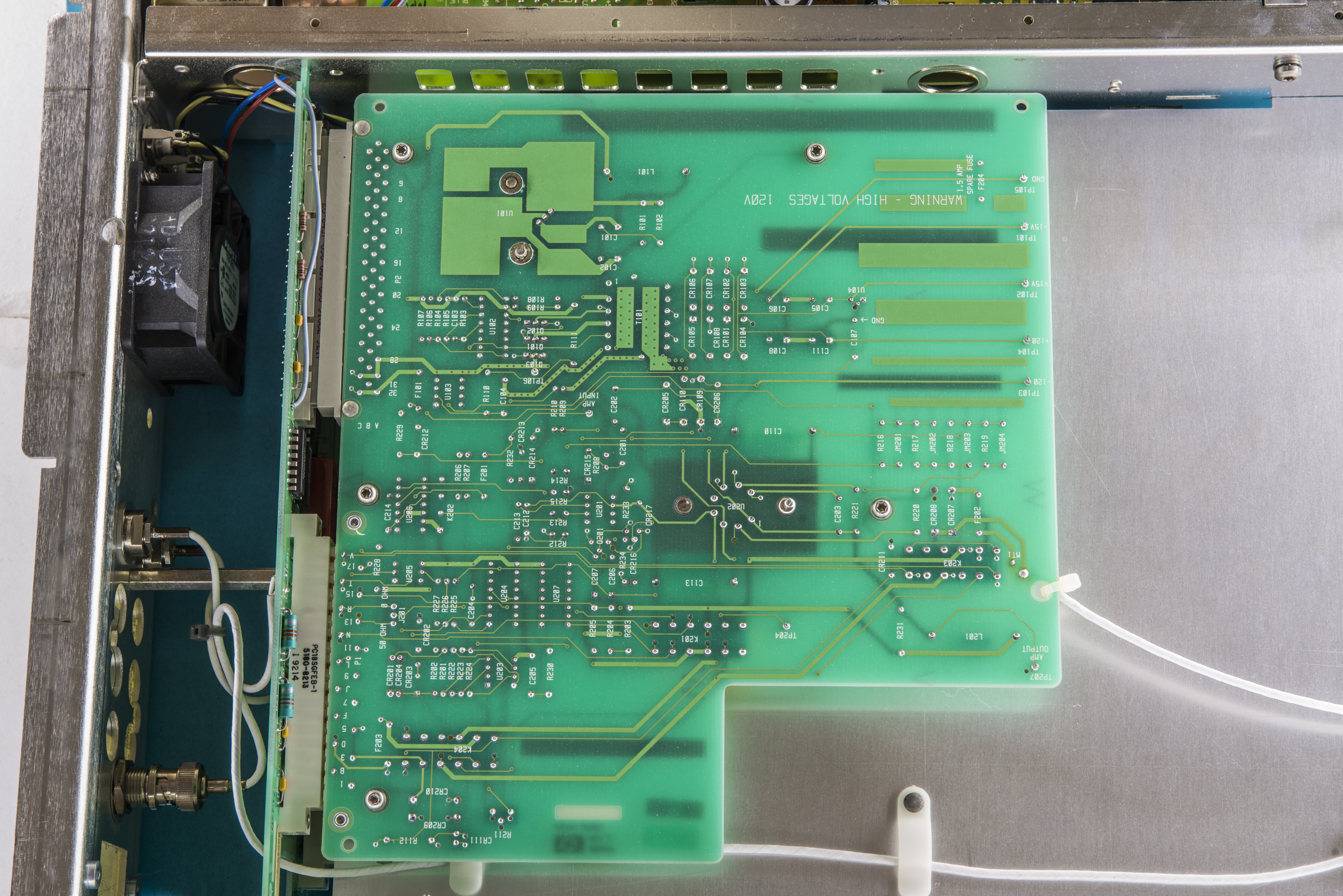
It’s always good to start debug from internal inspection and visual investigation of parts condition. Start diagnostics from power supplies, mechanical parts and protection circuitry, as that would be often point of first failure.
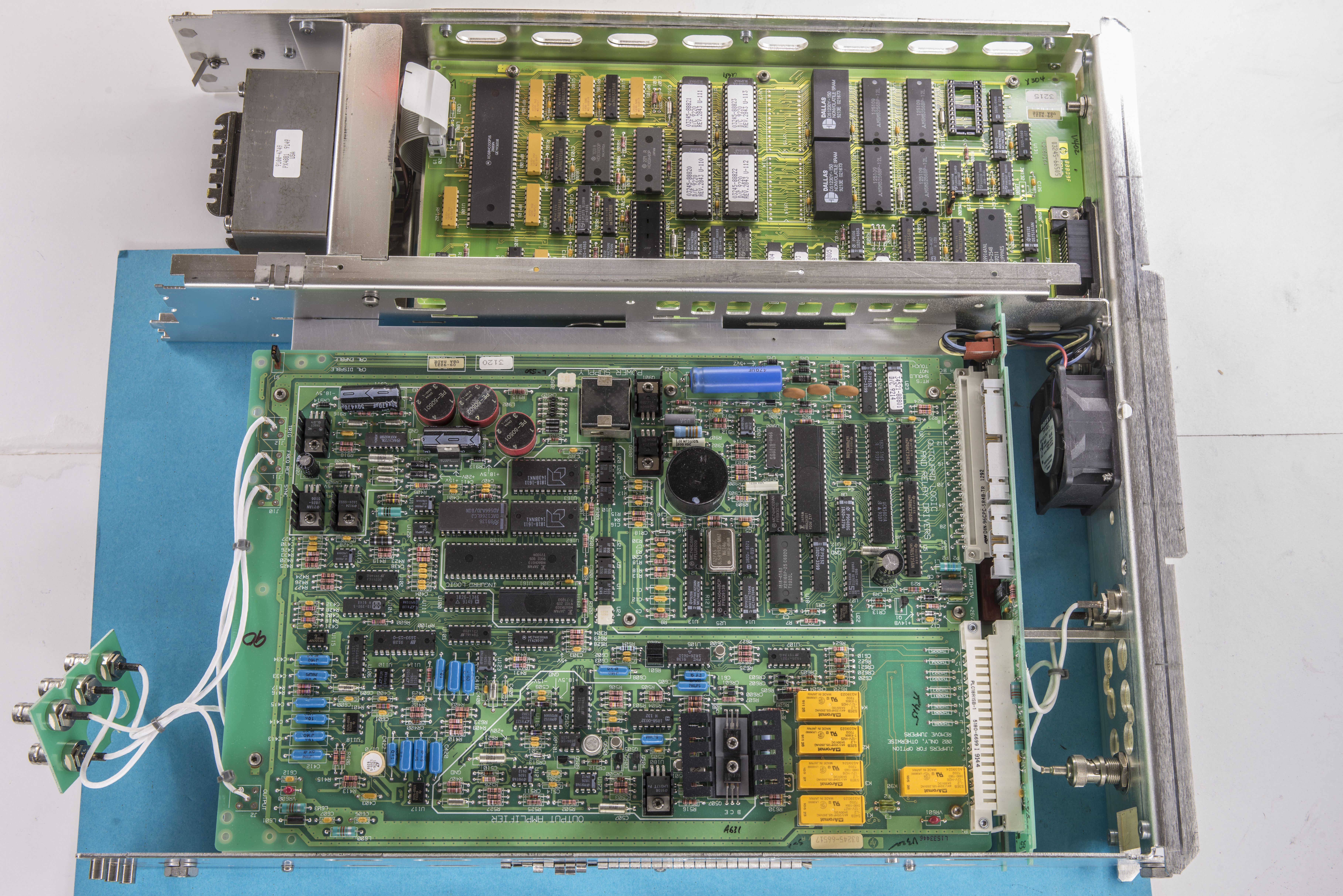
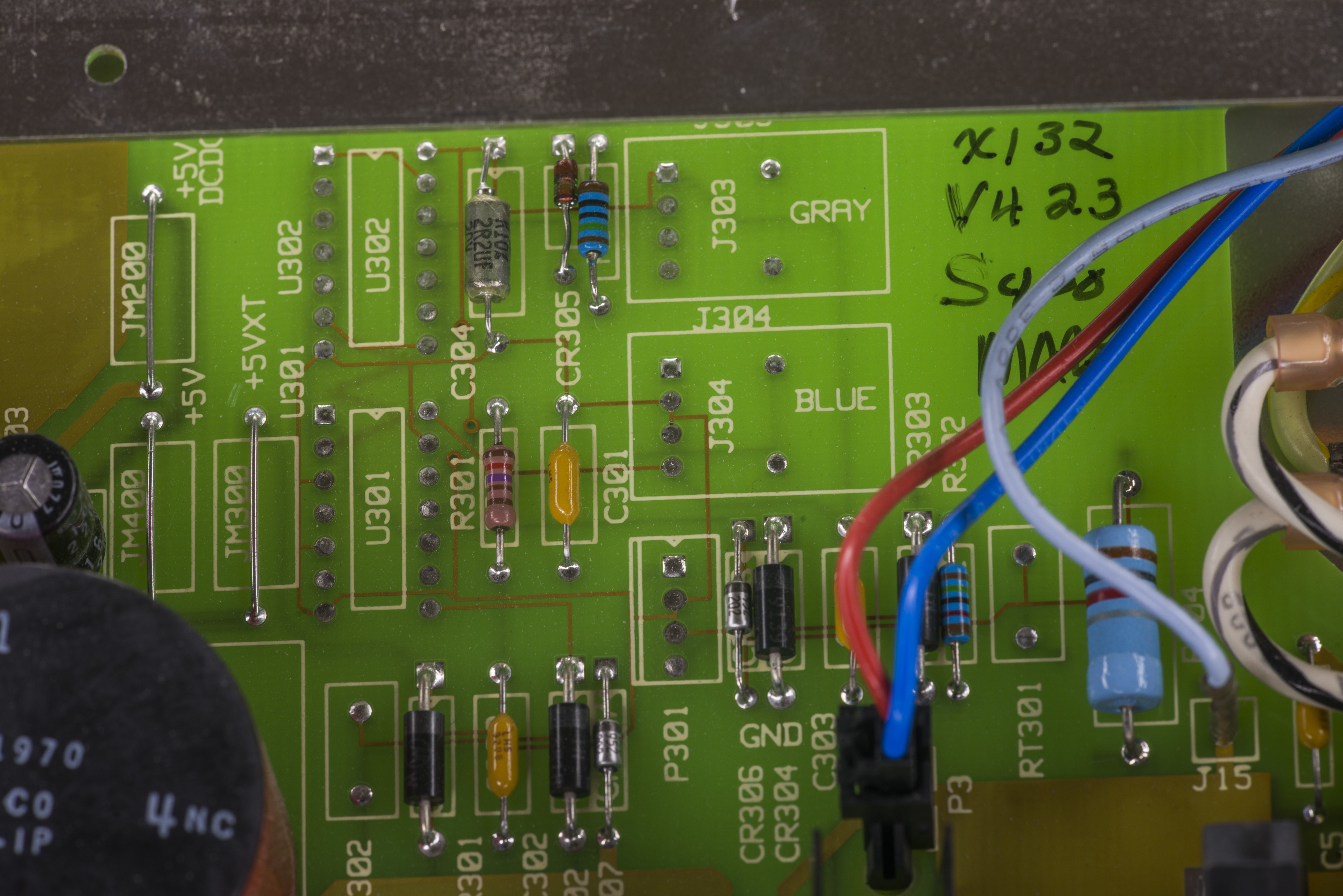
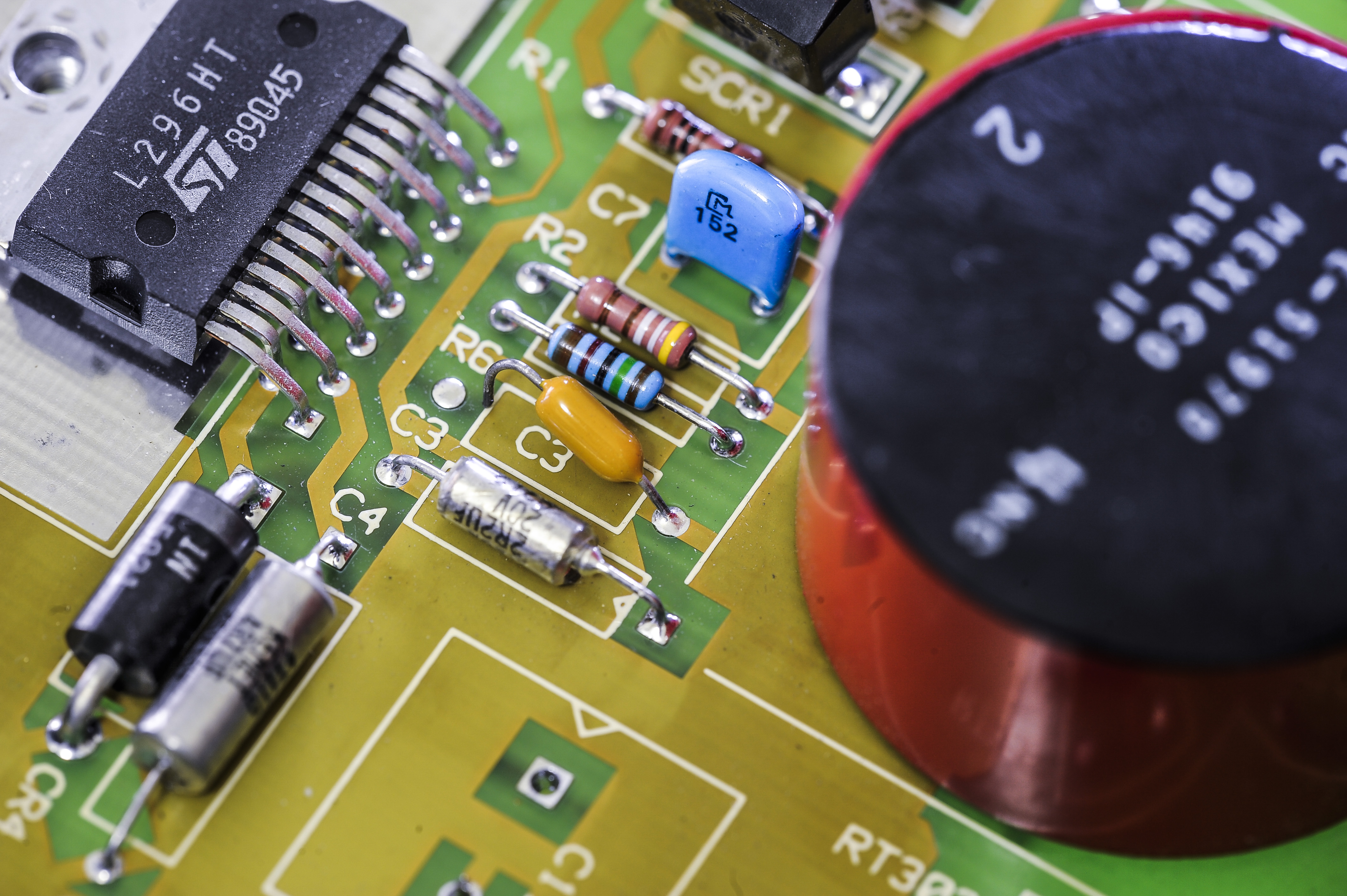
Let’s take a closer look on boards. Based on date codes, this unit was manufactured 20 years ago, in 1995. Overall internal condition I would mark as A, everything very clean, metal chassis is shiny and one could easily say this unit is just got out from factory. I am impressed to see so good preserved unit, after horrors of cleaning and fixing ours HP 3458A
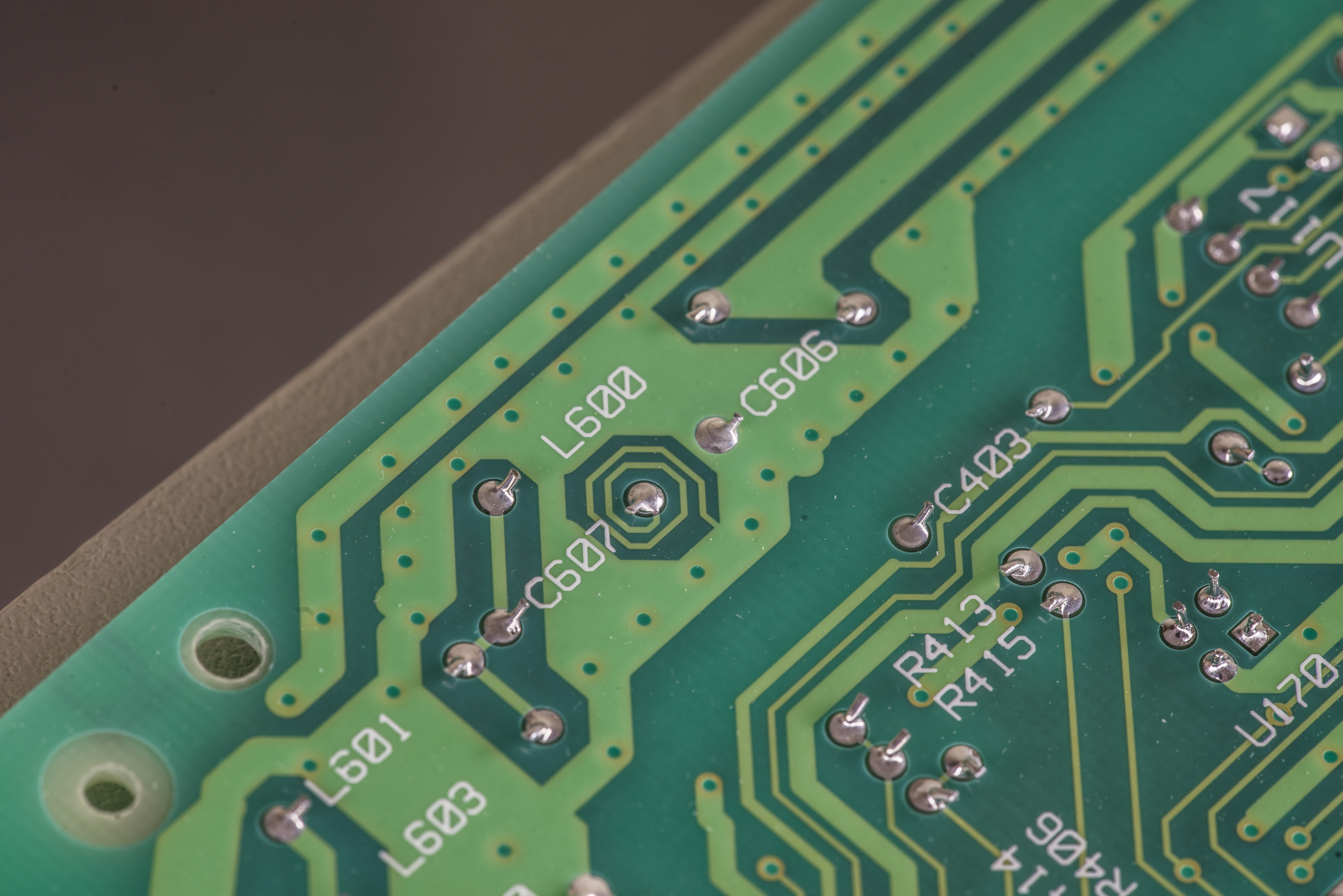
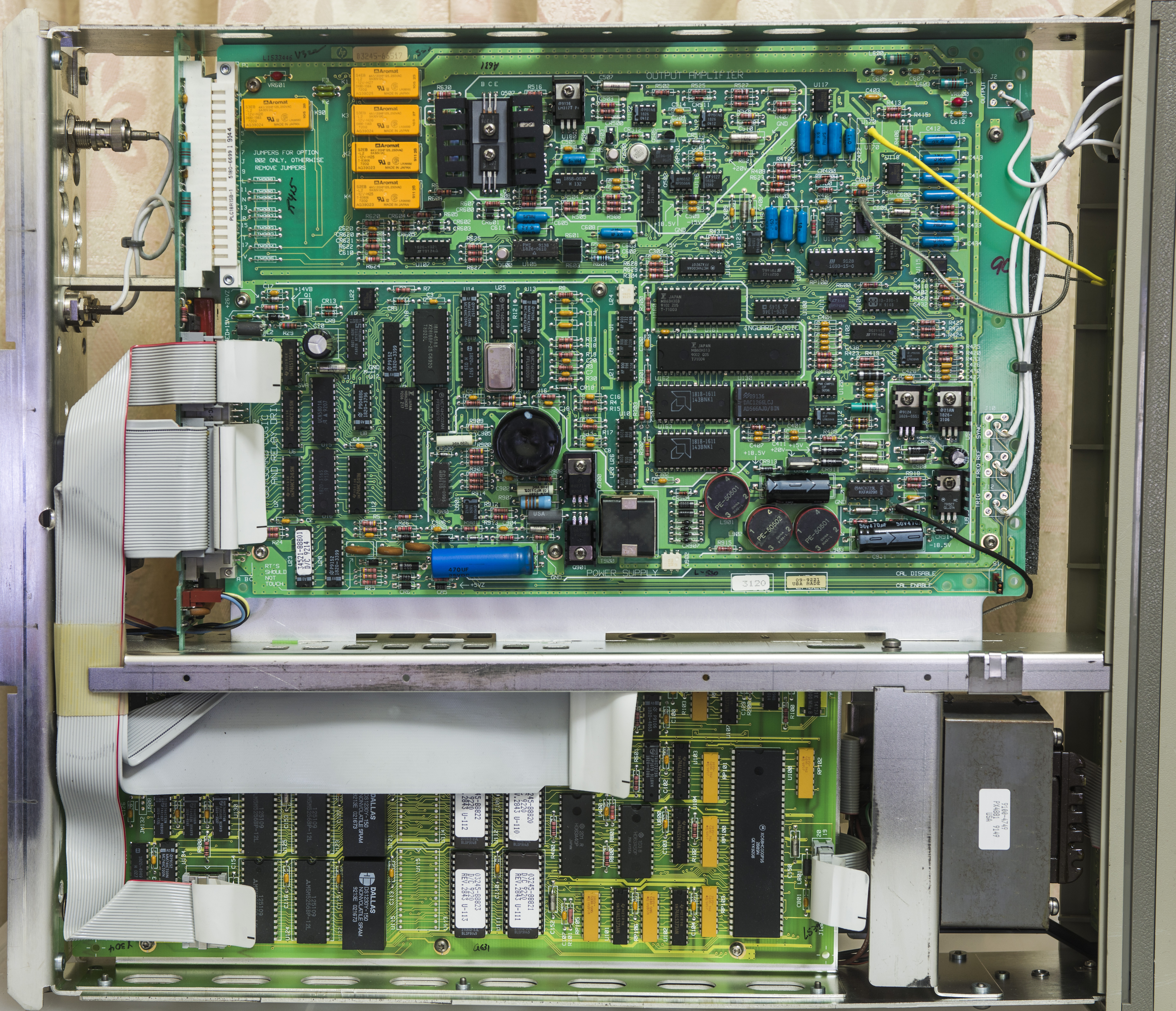
A1 Source assembly, Option 002

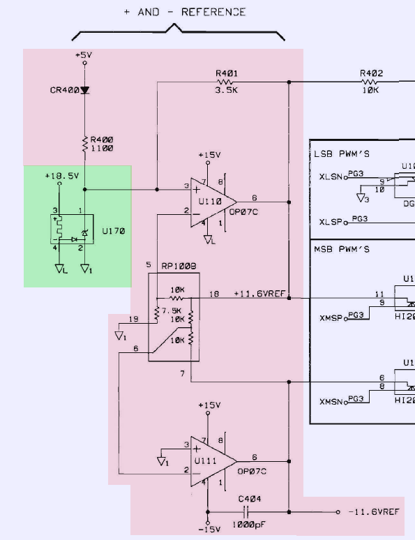
This board has Outguard digital and supply domain located in top right area and isolated inguard voltage/current source circuitry. Voltage reference is infamous ovenized buried zener, LM399 (or LM199, as part on board bearing HP custom number, and it’s hard to tell which one from LM199/LM299/LM399 is used).
There are no slots, covers or other fancy thermal/stress isolation techniques used around reference. Reference voltage is further scaled to stable ±11.6VDC by U110,U111 OP07C opamp and resistor network RP1008.
Isolated domain features 12-bit National Semi DAC1266LCJ for low-resolution output modes, and using discrete PWM DAC for high-resolution mode.
This low-resolution DAC was replaced before by previous owners:

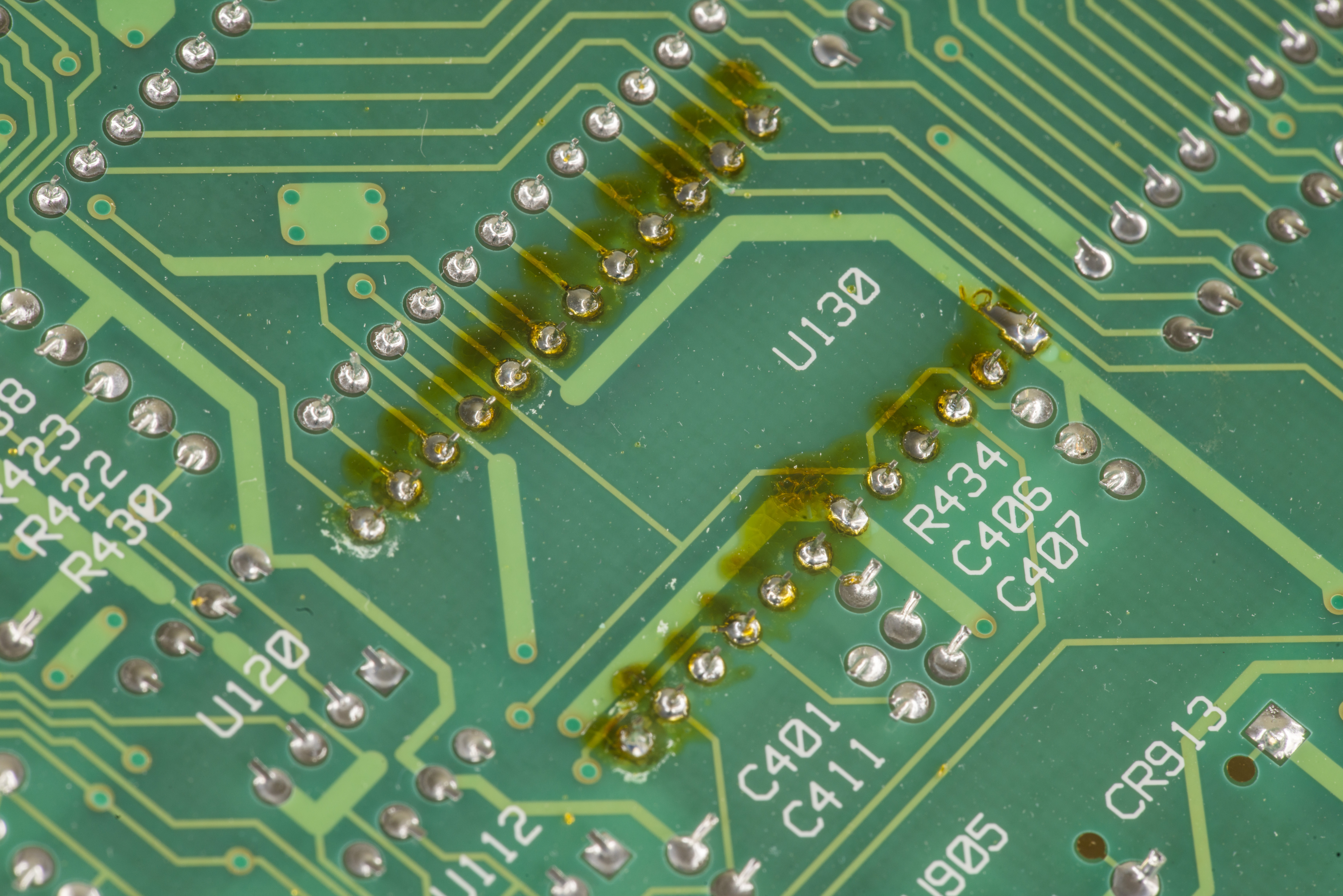
They did not bother cleaning flux though.
Digital domain have bunch of logic chips and gate arrays, and likely calibration EEPROM Xicor X2816.
A2 Backplane PCBA, Option 002
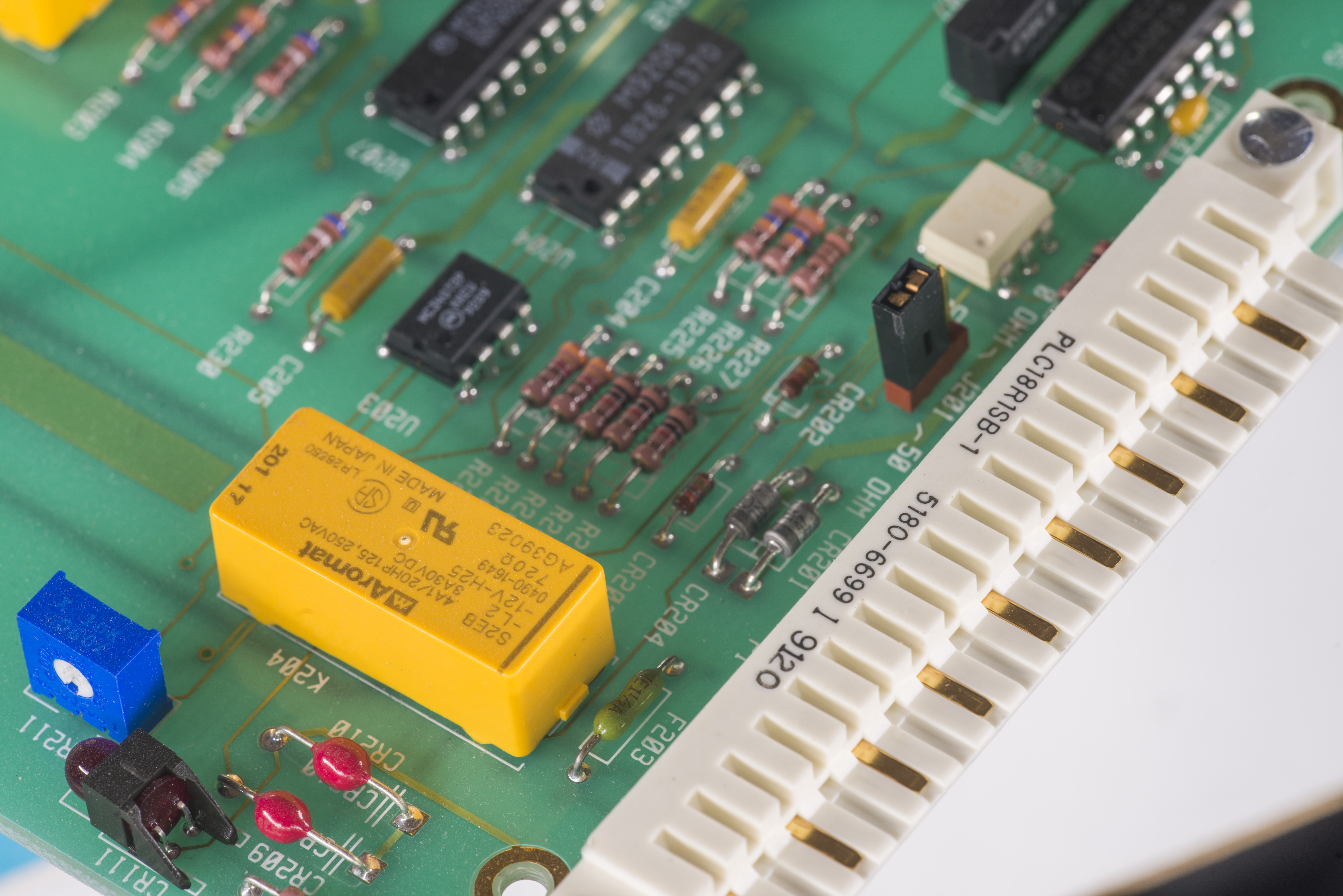

This board connects both cards, either two A1 PCBs for dual-channel option 001 unit, or A1 with A3 amplifier board for option 002 unit, like ours.
There is sole COTO reed relay located in center, and few logic packages on backplane PCB. Two opposite DIN-type connectors are used on each card, forming some kind of interlocking connection. Interface cables from A5 Outguard controller are connected to this backplane PCB.
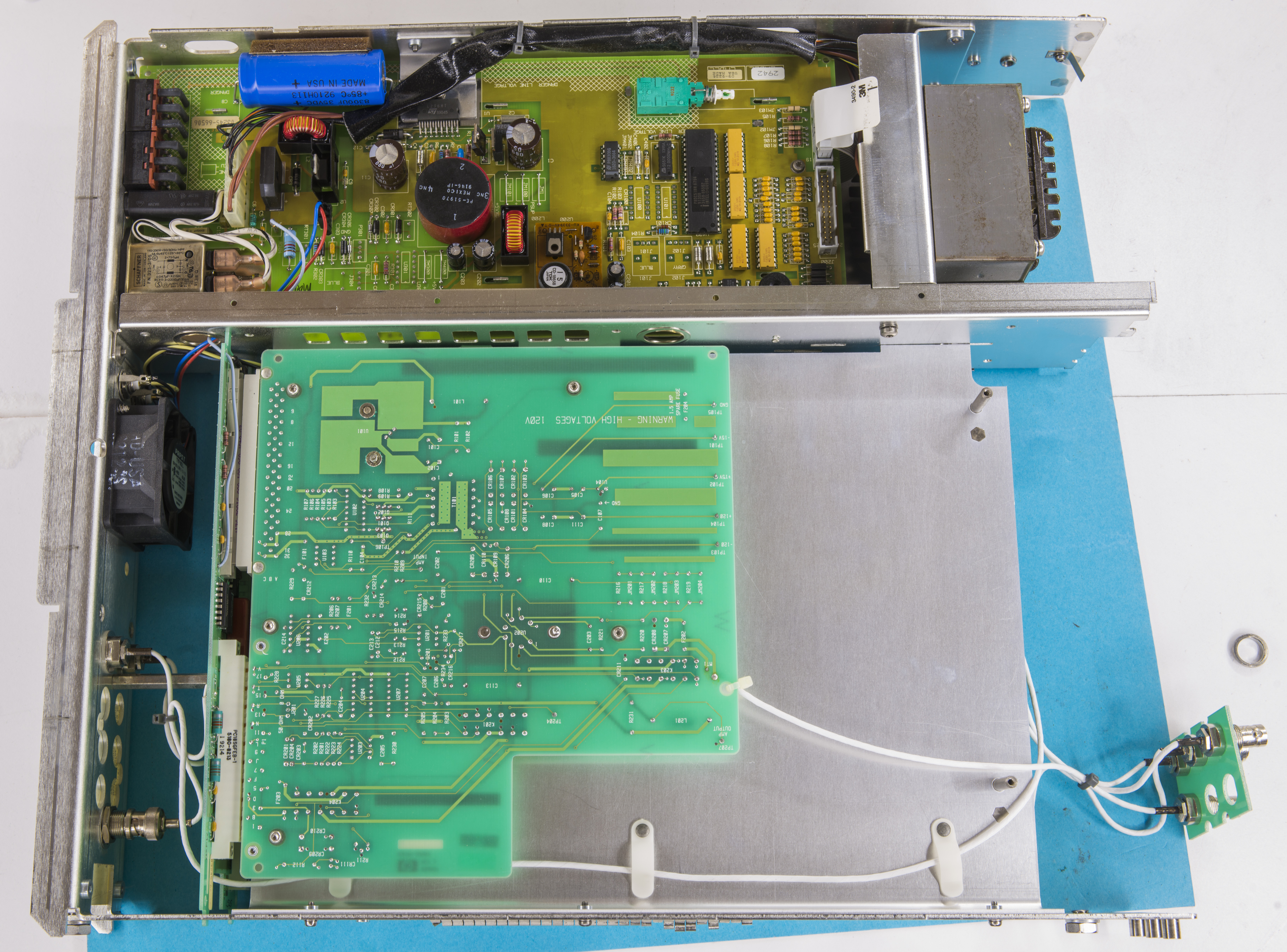
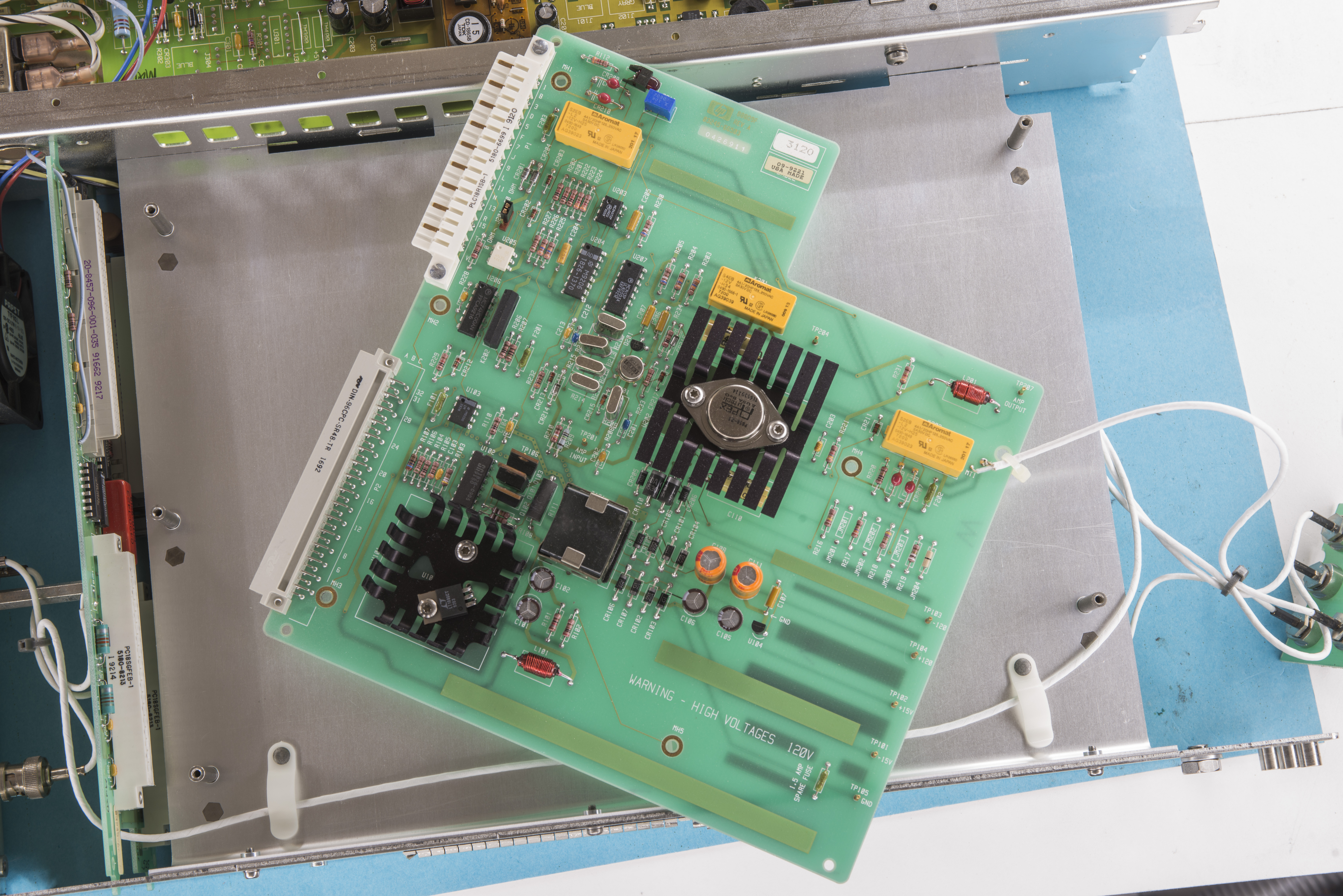
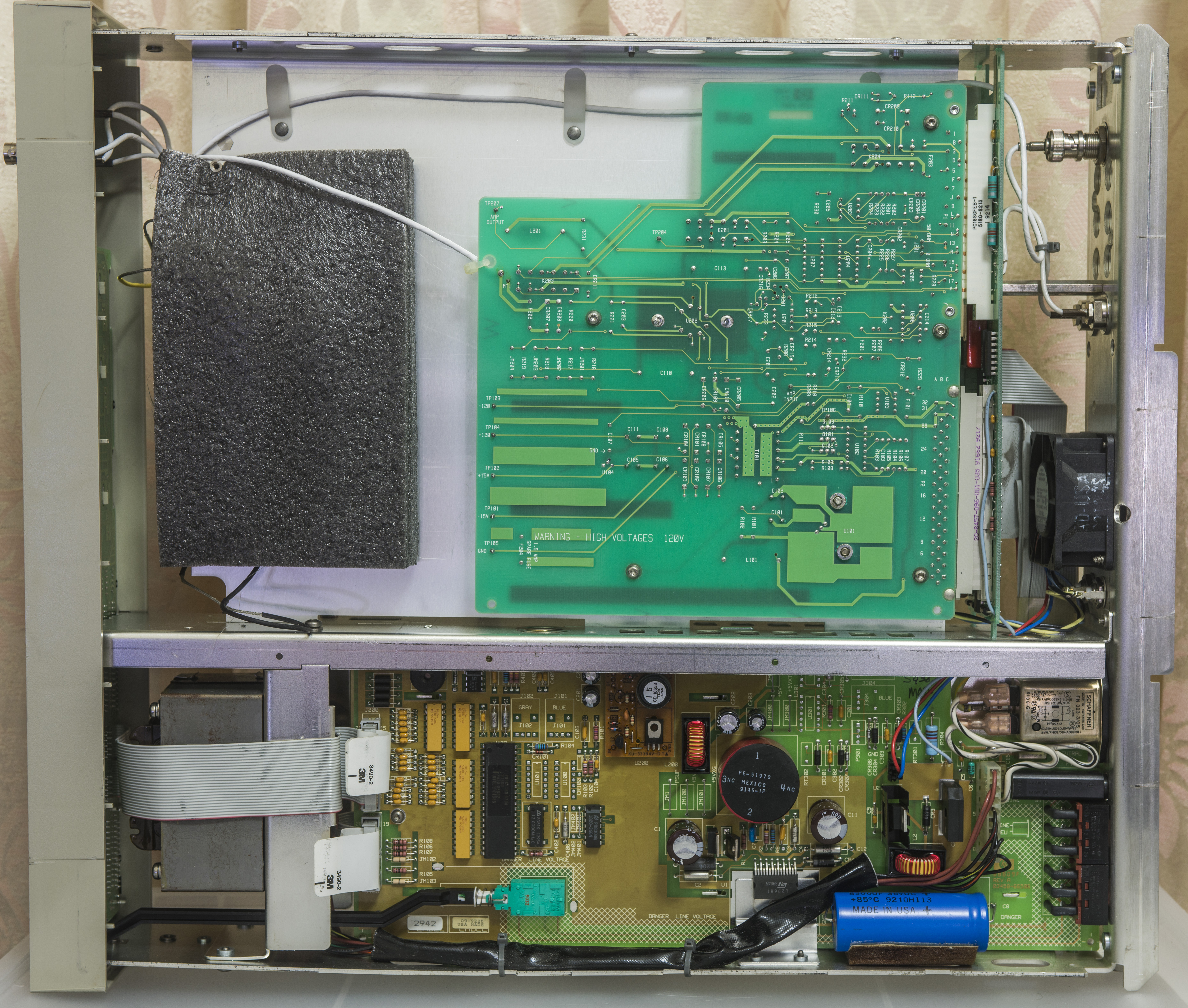
A3 (Option 002) High voltage x10 amplifier
Beware high voltages when probing and checking components on this board, as there are +120/-120VDC voltages present on it when live!
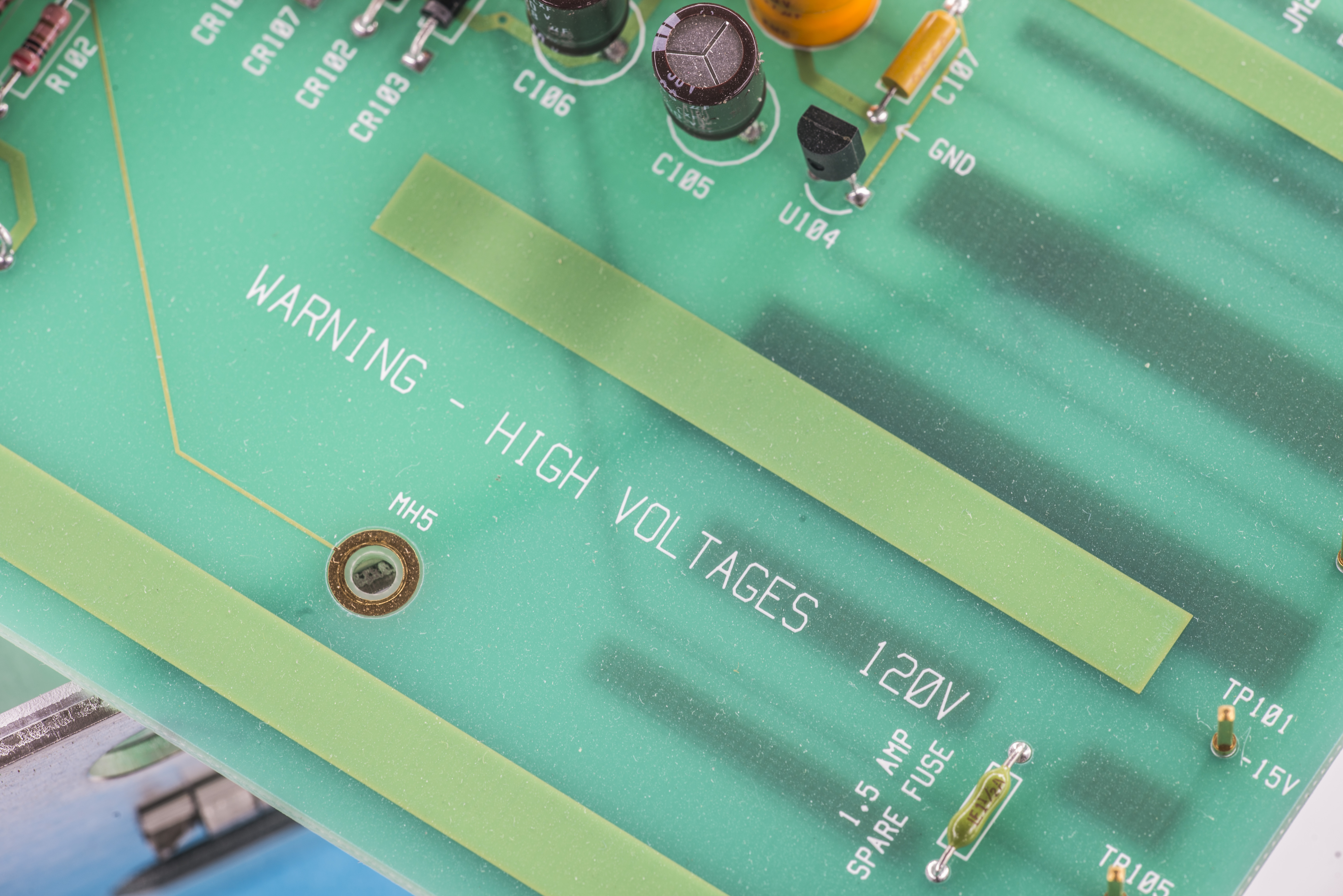
High voltage generated by push-pull DC-DC supply and rectified by diodes. As expected for 20 year old instrument
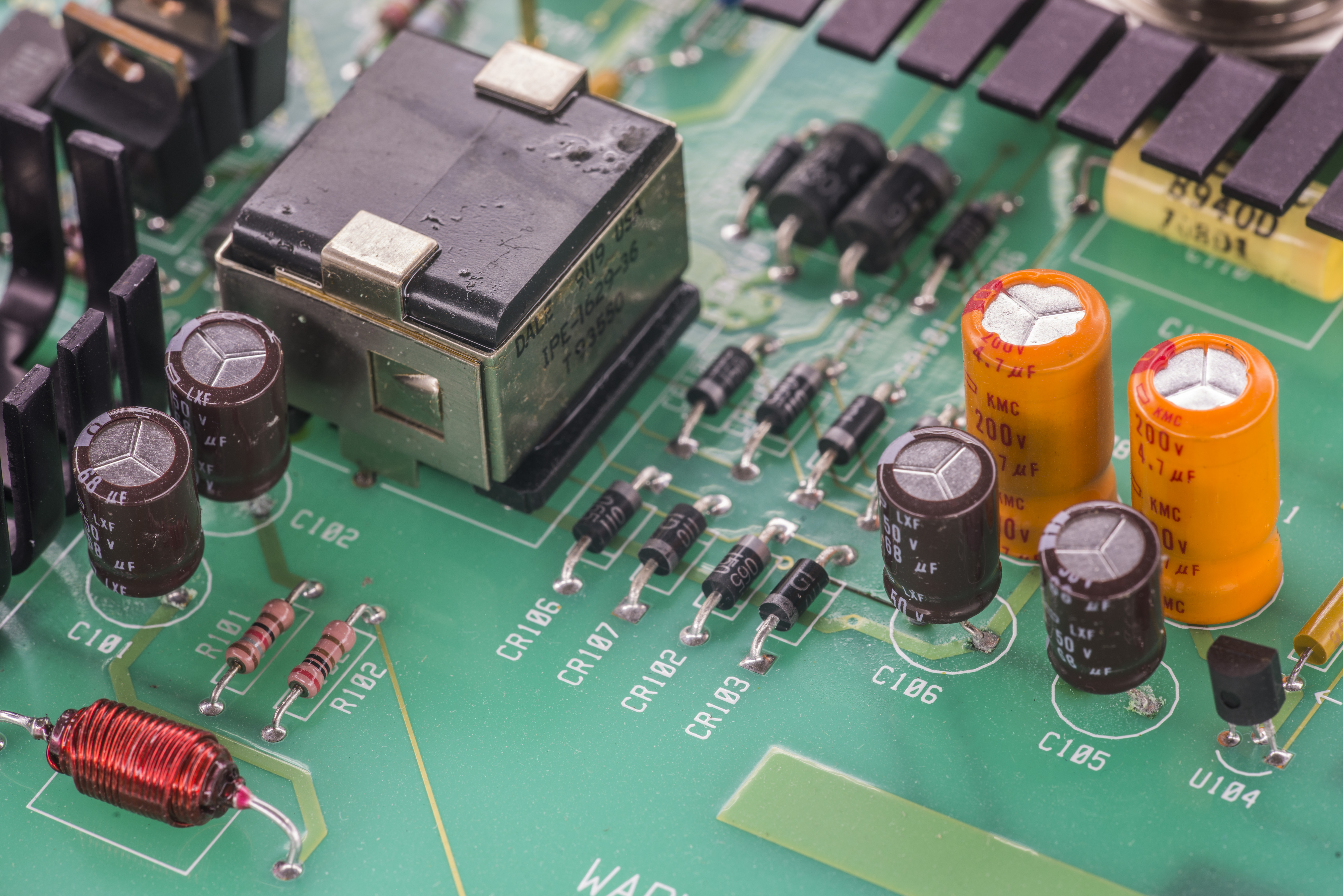
If you open high-resolution photo, it’s easy to spot spit electrolyte around 68µF 50V capacitors. Replaced them with new 100µF 50V Chemi-con’s right away.

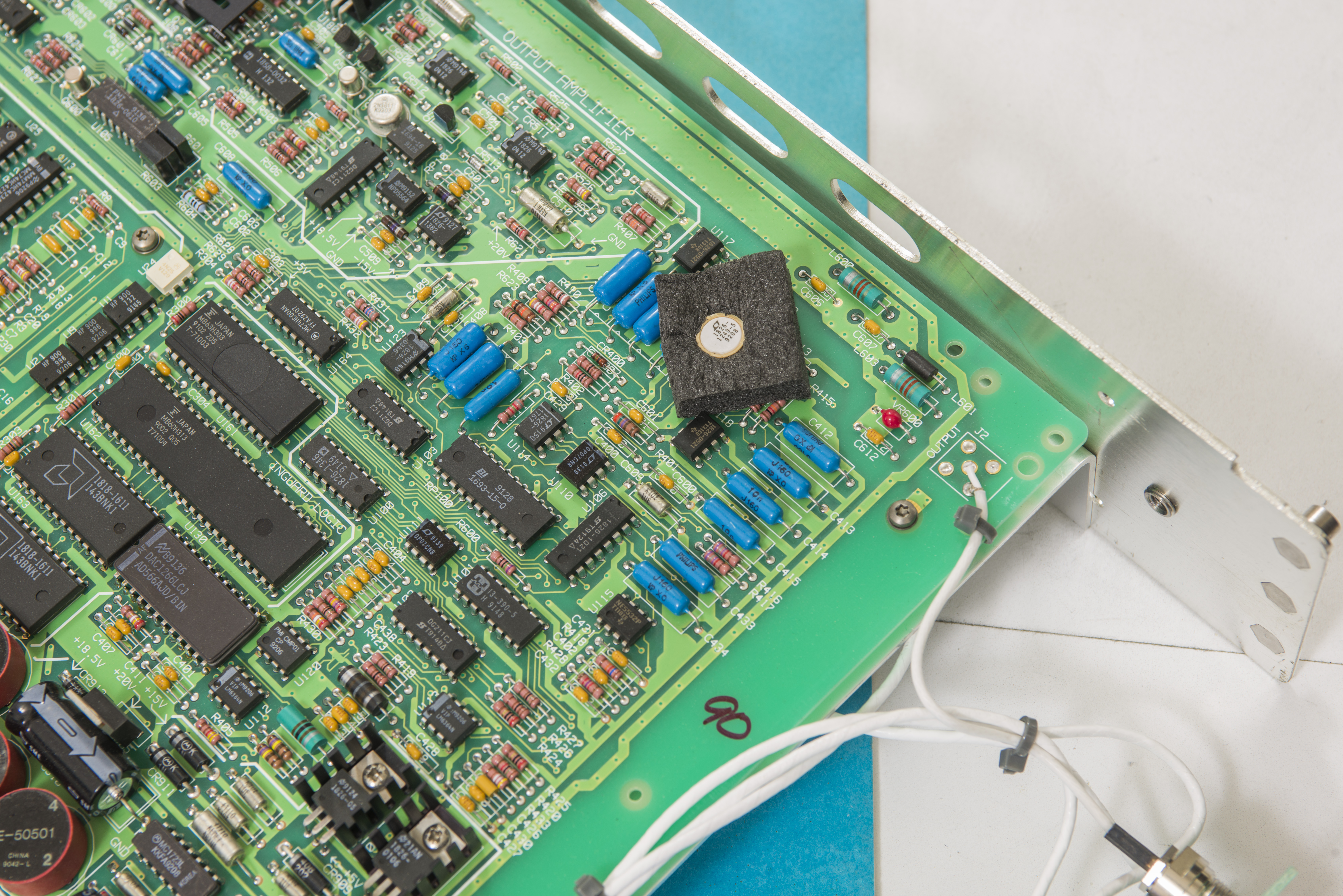
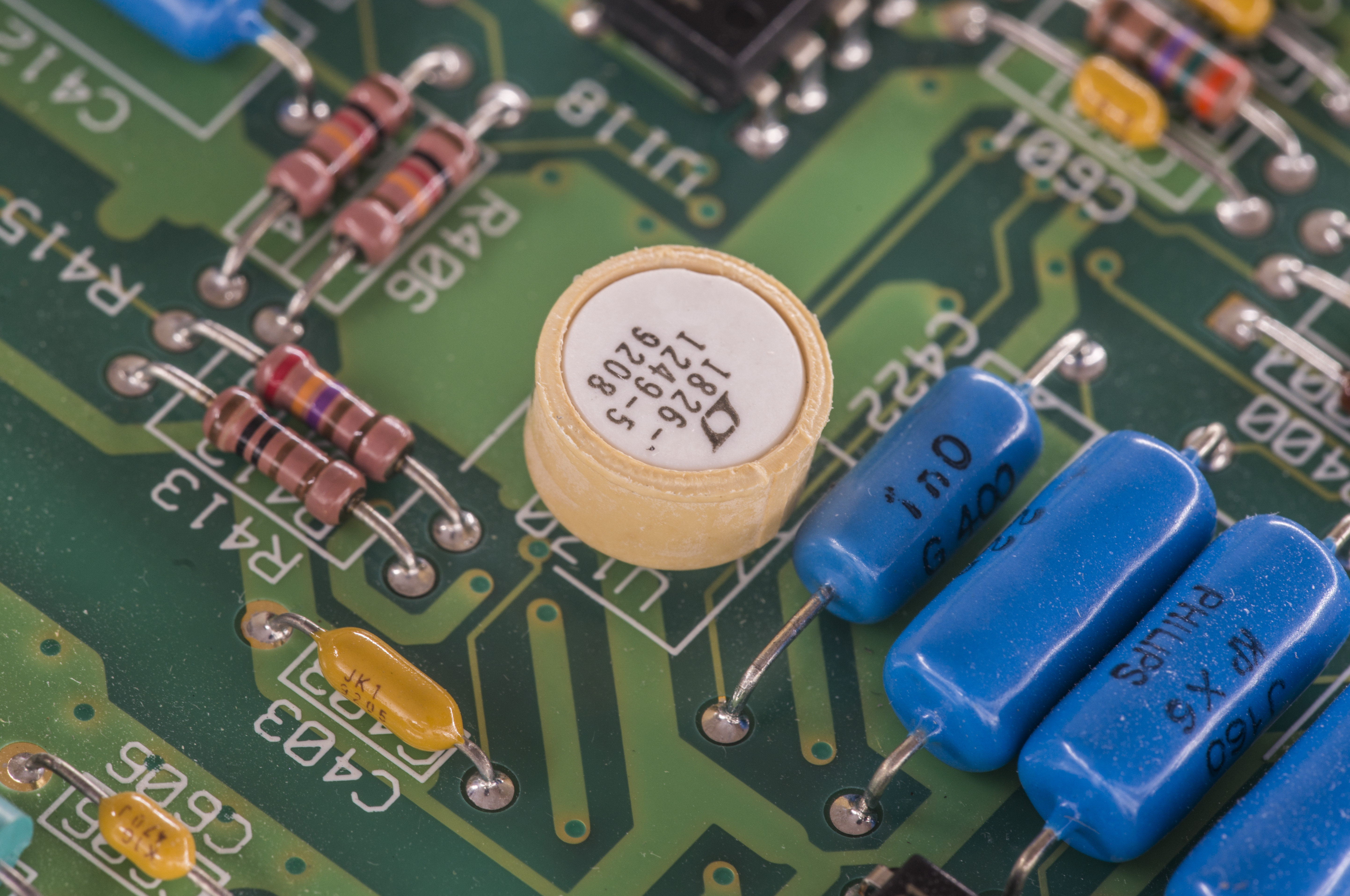
Big TO-3 package with BeO mark is high-voltage power amplifier PB58. APEX PB58 is able to provide 1.5Amps of current with those high voltages, dissipating up to 83W! This hybrid utilizes a beryllia (BeO) substrate, thick film resistors, ceramic capacitors and semiconductor chips to maximize reliability, minimize size and give top performance. Ultrasonically bonded aluminum wires provide reliable interconnections at all operating temperatures. The 8-pin TO-3 package is electrically isolated and hermetically sealed using one-shot resistance welding.
Excited? Yes, it’s expensive, the price of such high-voltage amplifier currently about $158 USD on Digikey. This is main power amp, which converts low voltage input from A1 PCBA to high-voltage output. Together with small feedback/drive opamp this forms x10 output.
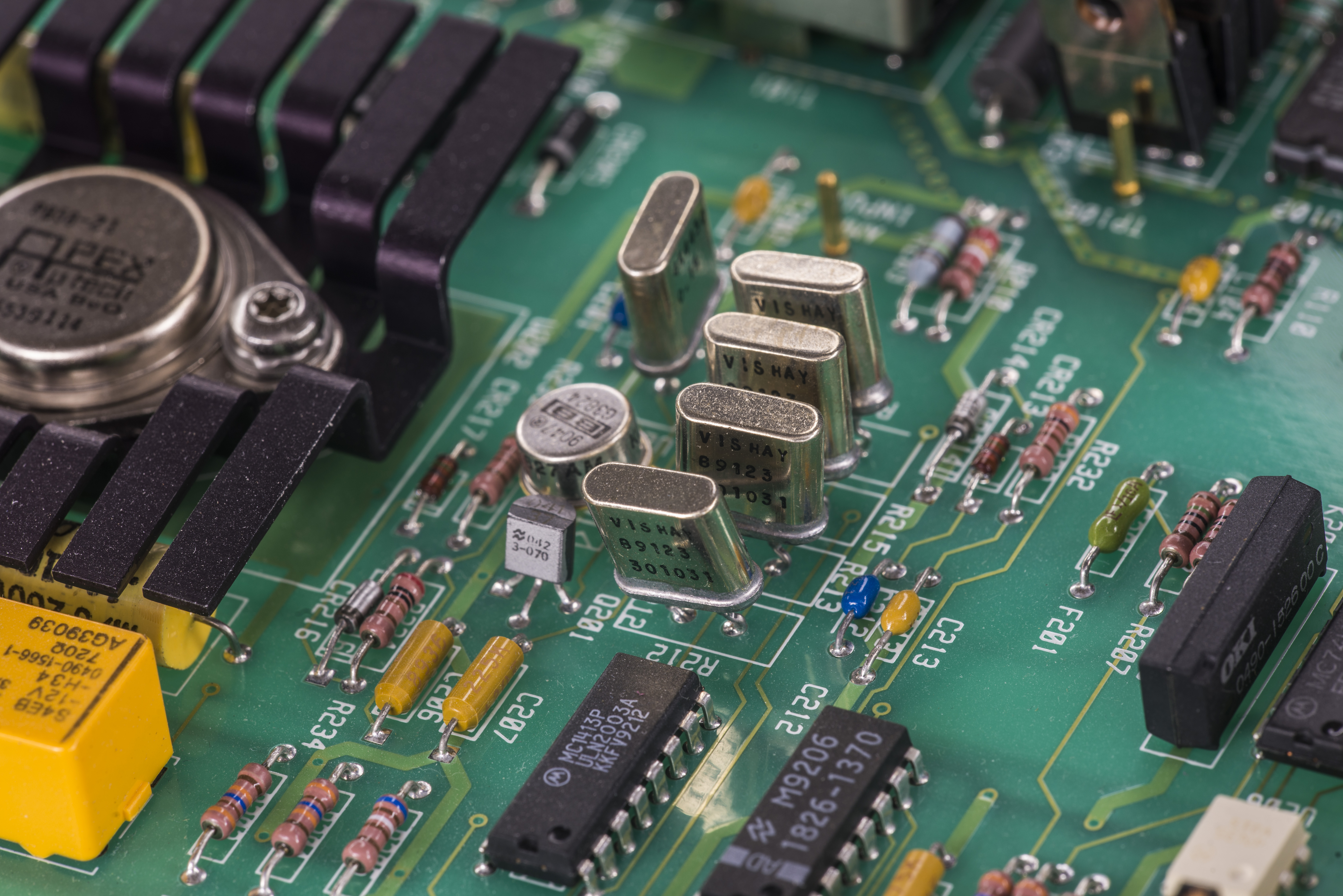
There is couple of hermetic Vishay Precision Group metal foil resistors, used in output amplifier feedback network. It’s mandatory to keep these stable, so output would not drift due to environment/signal changes.

Closer look on them shows four pieces 40K000 and one 4K4 around OPA627 metal canned precision opamp. This opamp drive high voltage APEX Beo power amplifier, which is powered by ±120VDC supplies.

All output and interboard connections are done with Teflon insulated coax wire, which is required by ability of sourcing high voltages with frequencies up to 1MHz.
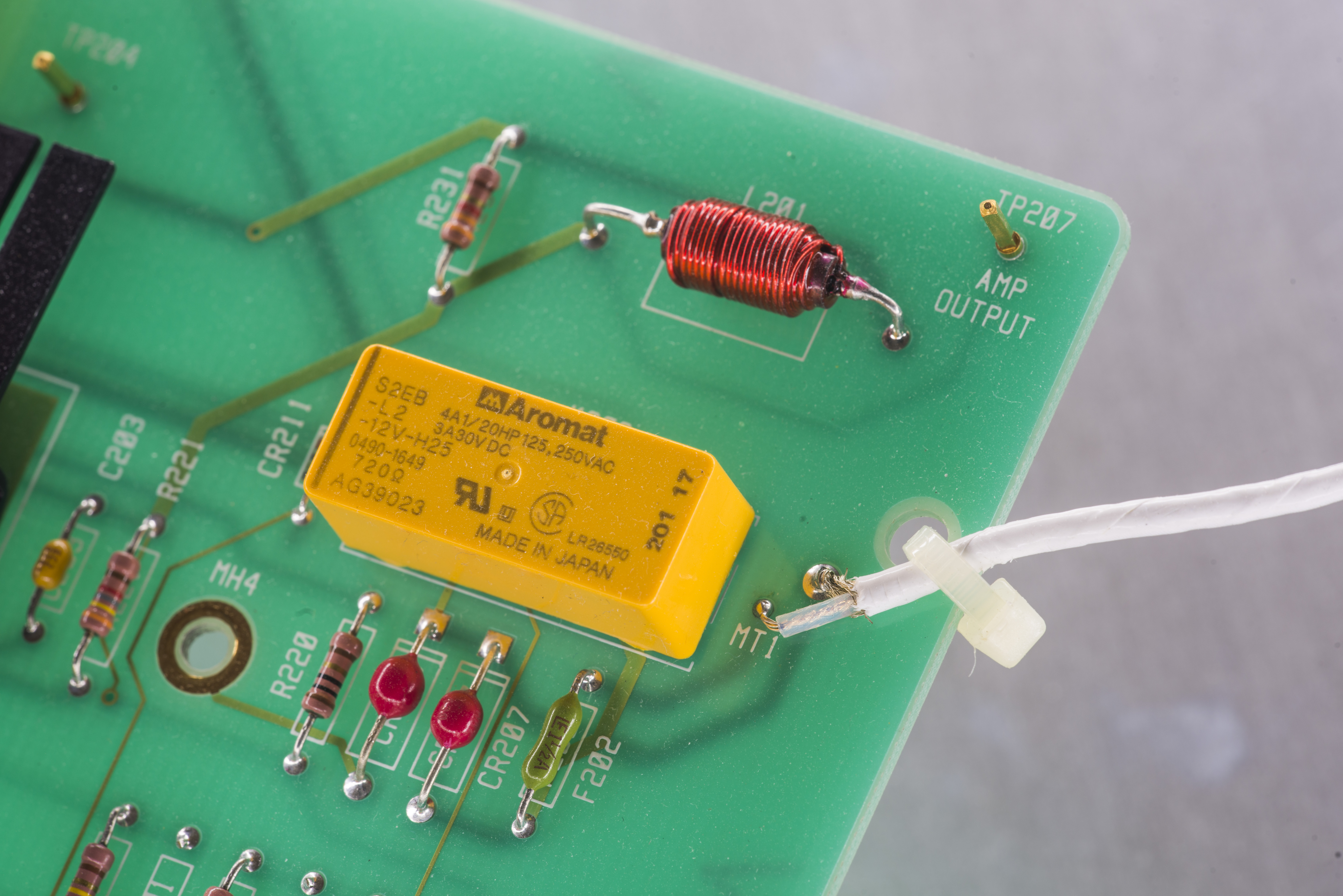

There is also single unit’s trimpot, for adjusting zero offset on A3’s x10 amplifier. It is backlit with red LED so you can see it even without covers removal. This is actually part of calibration procedure for A3 PCBA.
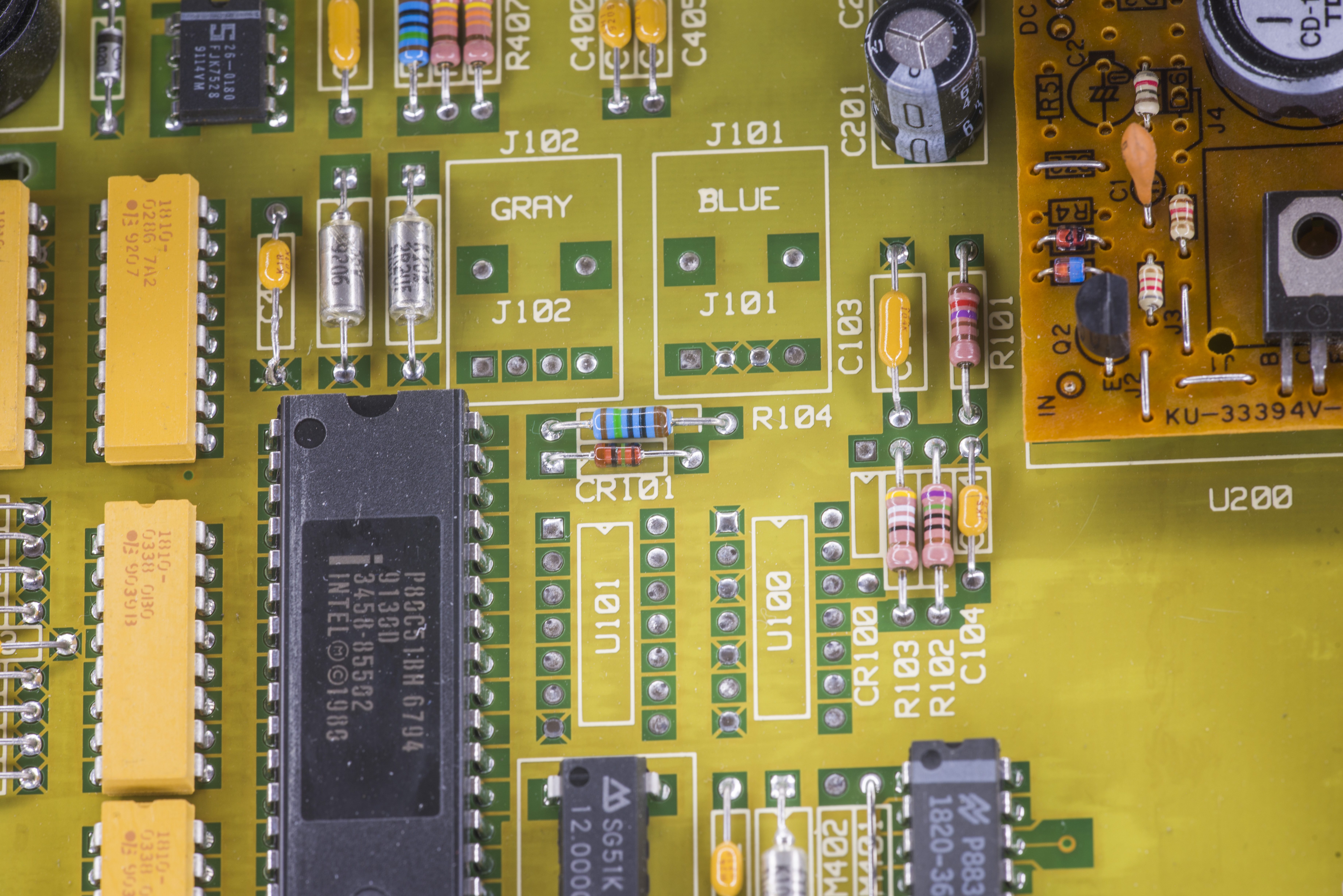
A5 Outguard controller
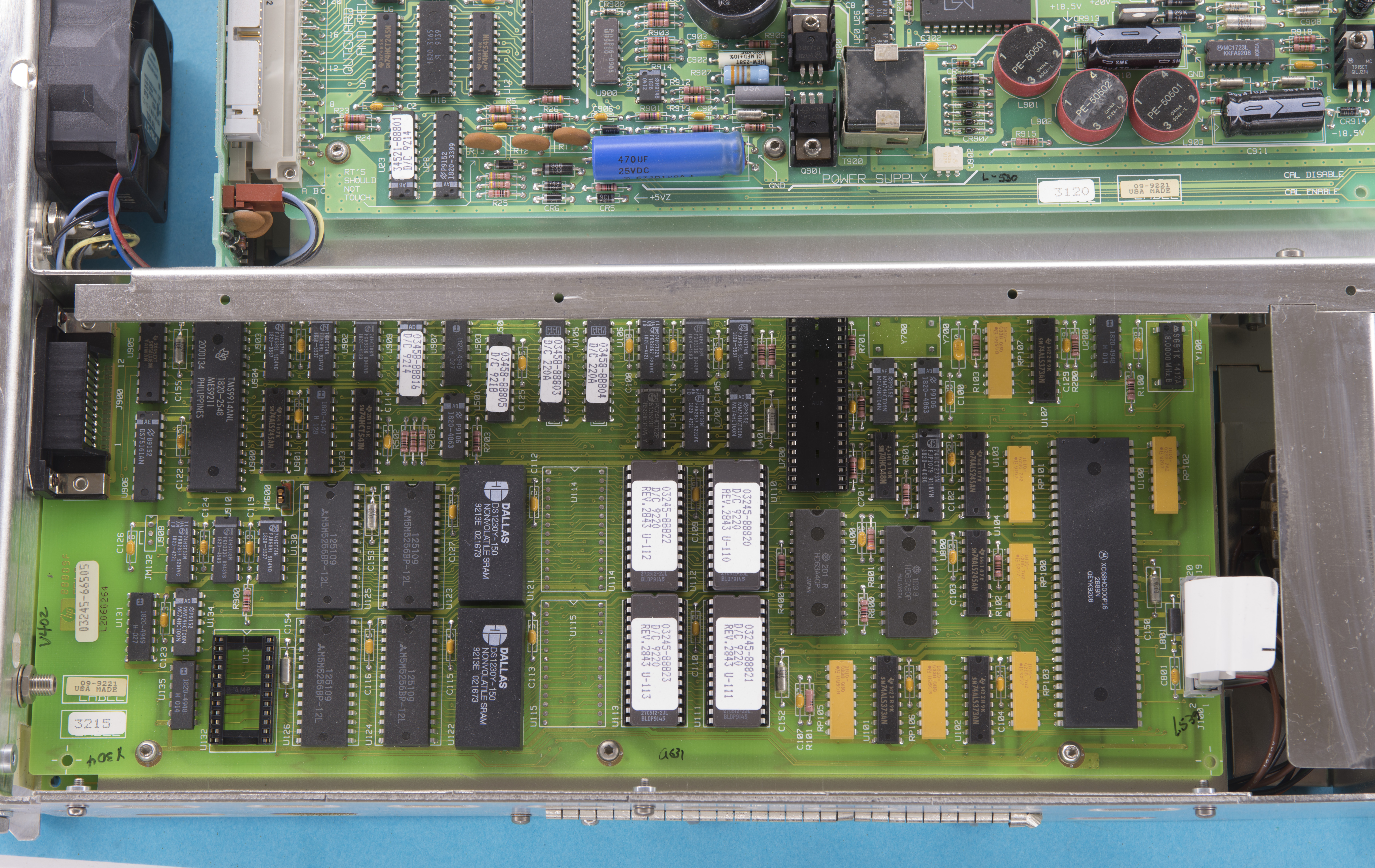
This board featuring main digital processor, NVRAM, GPIB and glue logic for interfacing rest of meter guts. It’s exactly same PCB as 03458-66505, with only difference in BOM and populated parts.
Differences from 3458A featured board:
- 3245A using four ROM chips instead of six
- Socket for ribbon cable coming from U700 position, instead of logic 3458A’s ASIC
- Socket for ribbon cable coming from calibration NVRAM position, instead of DS1220 on 3458A
- Missing clock generator near U700
A6 Outguard power supply
This board is exactly same PCB as 3458, as in fact using same PCB model number. The only difference spotted – missing VersaLink optical isolation circuits and optics.
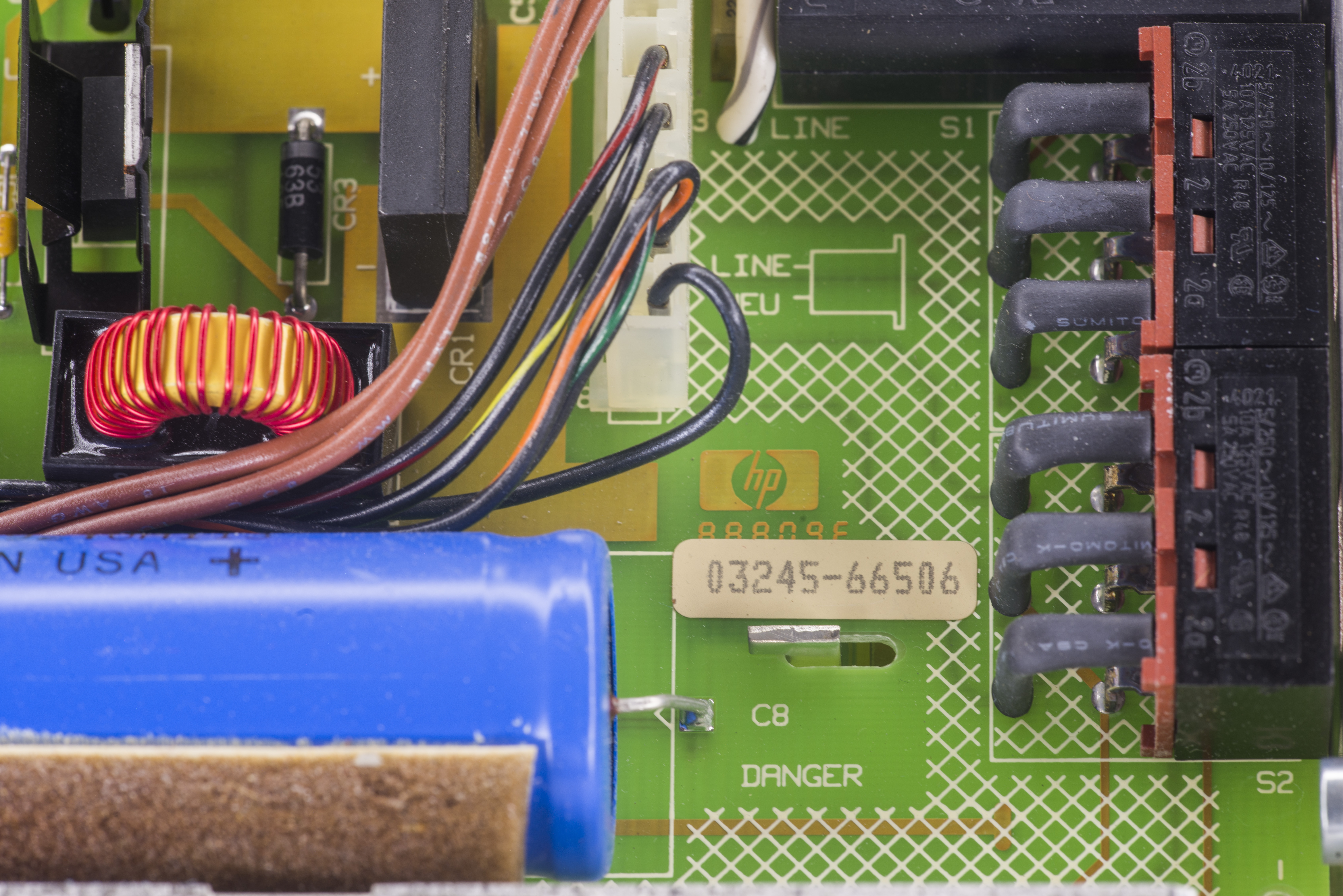
There is same Schaffner FN 323-3/05 mains filter, some of which prone for explosions and failures. I’ll replace this with fresh Delta later.
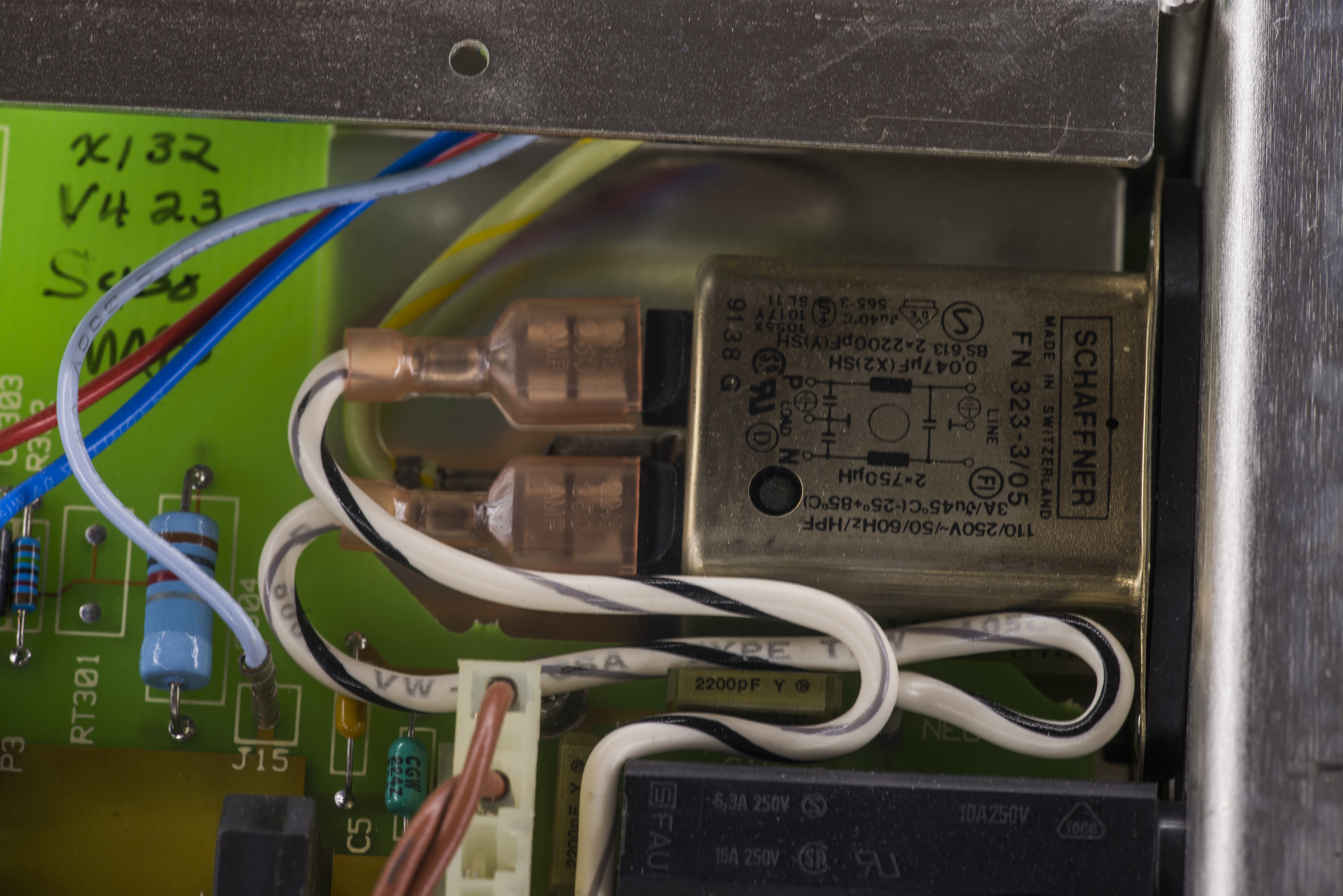
New DELTA filter in place:

Also spotted unsoldered cap, likely slipped thru QC :)
Fixed.
A7 Display logic
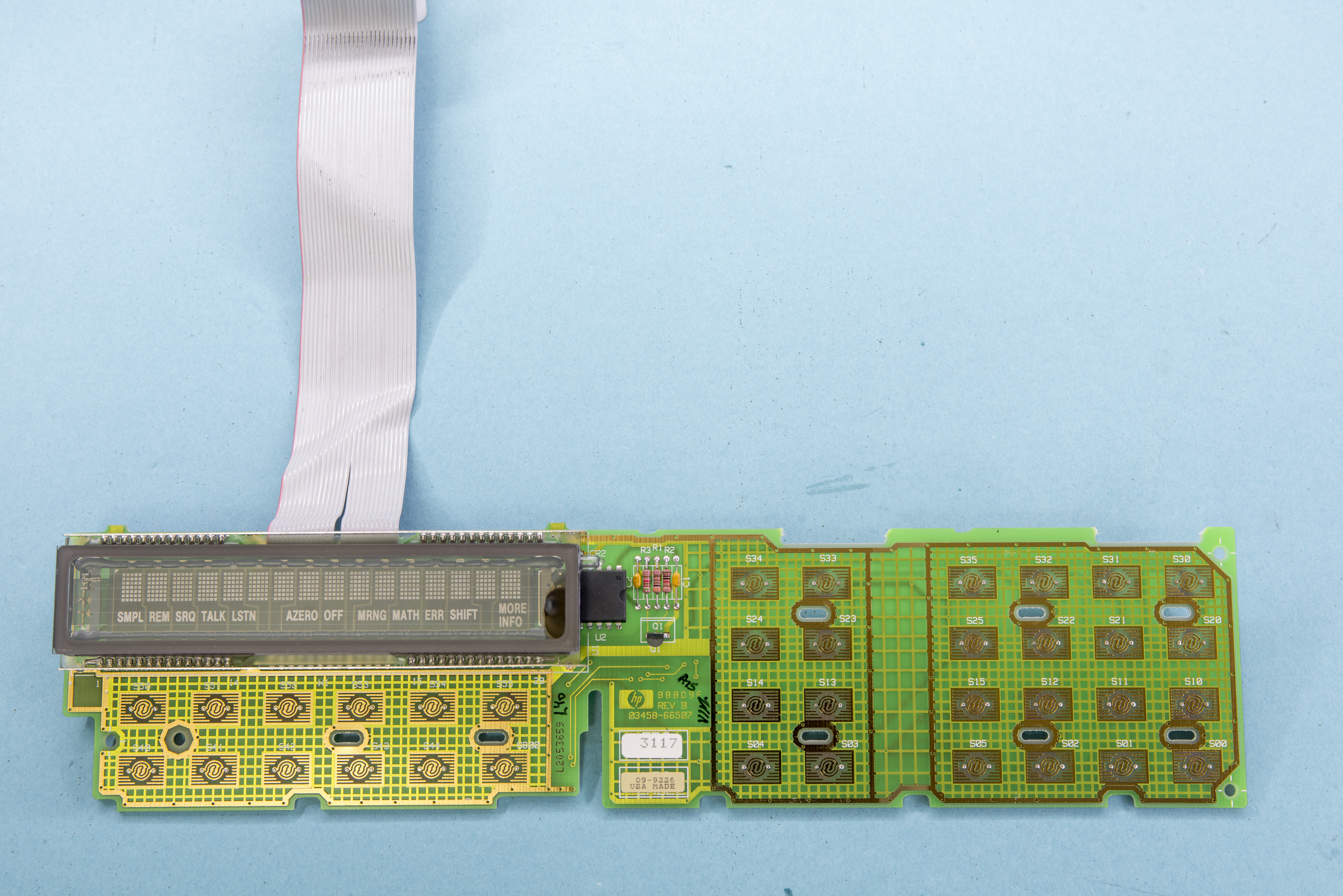
Front panel board is exactly the same as A7 from 3458A. VFD glass is little bit different (auxiliary segments like “MATH”, “SHIFT” on bottom row are more think/bold), but I believe that’s just different batch of same glass. Having same front panel can be a good news for someone who can buy 3245A cheap, in order to salvage front panel for 3458A. This is same matter of BOM unification, similar to Keithley using same dual-line VFD displays across wide variety of instruments.
Repairs
Cleaning front panel
I like to keep my tools clean, so first thing I did was removing front panel and cleaning it with IPA and soapy water.
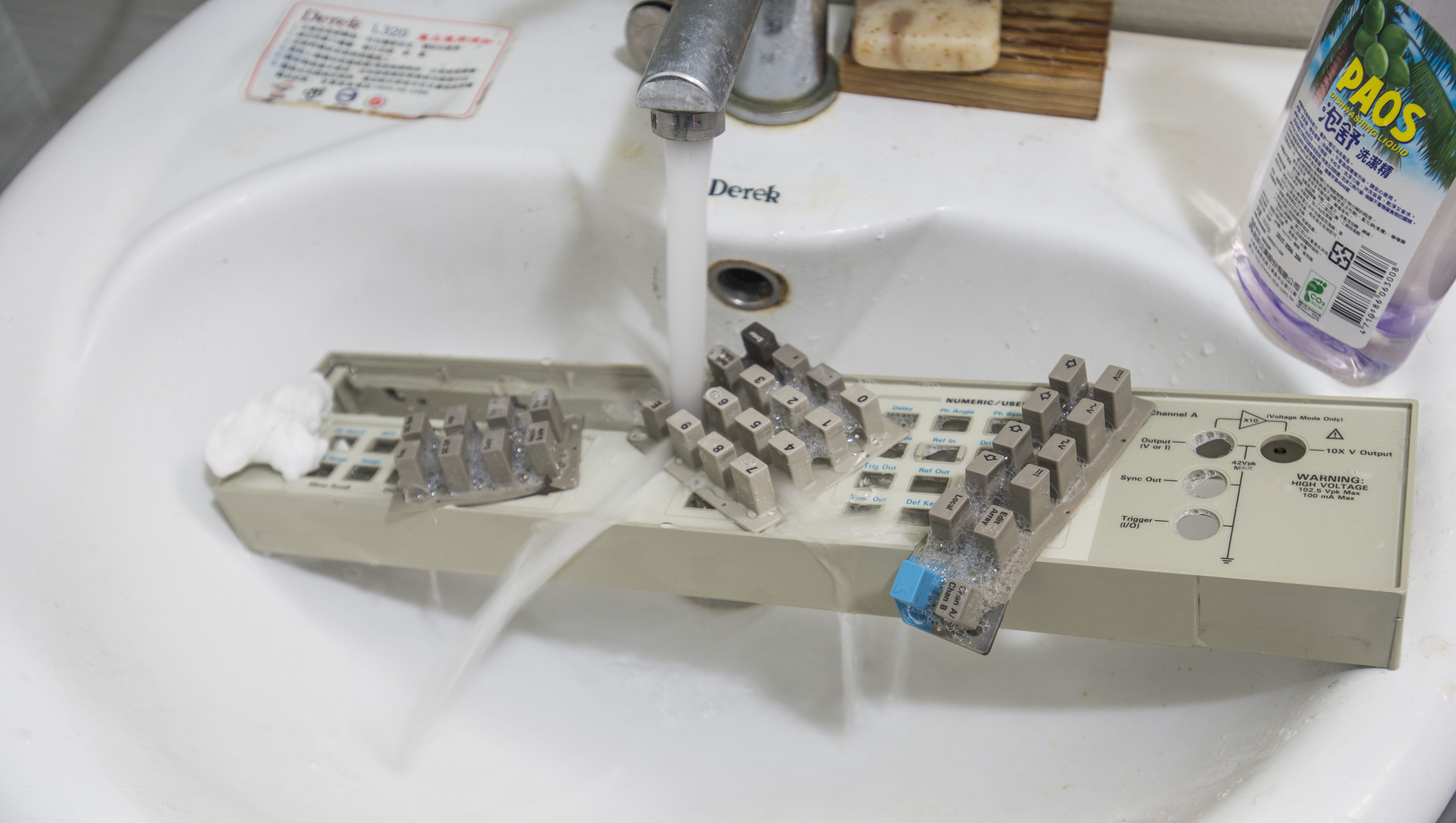
All sticker residues are cleaned off, panel look almost like new now. Pleasant looks and feel during operation guaranteed.
Power up issue.
Main interface cable from U700 position on A5 PCB and A2 Backplane PCB was barely holding in pin header socket, being a root cause of unit power up problems. After reseating cable all issues were resolve and 3245A started to operate normally. This was easiest repair possible.
Firmware
You can determine firmware revision via the front panel command “Rev?”.
In many cases an old unit might have been retrofitted with newer firmware, so later firmware revision cannot be used as proof of the date of manufacture.
Firmware ROM dumps from TMS27C512 ROMs for HP 3245A, read by general purpose ROM programmer, MiniPro TL866.
To generate single binary I used simple python snipped like this
# xDevs.com Firmware combine tool
# https://xdevs.com/fix/hp3245a/

import os

with open('03245-88820.BIN','rb') as a:
    with open('03245-88821.BIN','rb') as b:
        with open('03245-88822.BIN','rb') as c:
            with open('03245-88823.BIN','rb') as d:
                with open('output.bin','wb') as x:
                    for cnt in range(0, 65536):
                        x.write ("%c%c" % (b.read(1),a.read(1)))
                    for cnt in range(0, 65536):
                        x.write ("%c%c" % (d.read(1),c.read(1)))
It takes input files and combines them into single binary ROM.
Other accessory for meter
Since this unit using exactly same chassis as 3458A, it’s rackmount kit is compatible and available under P/N 3458A-909 for $110 USD.
Performance verification
Measurements with voltage references, foil resistors, ESI decade, frequency, period, currents, temperature, RTD
Prior to any calibration on adjustments I decide to test output ranges and see which areas are out of specifications. Test points are taken from calibration manual performance verification section.
I used freshly repaired HP 3458A, which was self-calibrated using Keithley Model 2001 as a transfer standard. This Keithley was calibrated by Tektronix in Feb/2014 was used in this test, as currently is most accurate unit I have.
| Test item output | Measured result | Deviation | Allowed range | Test result |
|---|---|---|---|---|
| HiRes DCV 1.25 VDC | 1.250 ±0.000084V | |||
| HiRes DCV 0.625 VDC | 0.625 ±0.000057V | |||
| HiRes DCV 0.0 VDC | 0.000 ±0.000031V | |||
| HiRes DCV -0.625 VDC | -0.625 ±0.000057V | |||
| HiRes DCV -1.25 VDC | -1.250 ±0.000084V | |||
| HiRes DCV 10.25 VDC | 10.250 ±0.000570V | |||
| HiRes DCV 5.125 VDC | 5.125 ±0.000375V | |||
| HiRes DCV 0.000 VDC | 0.000 ±0.000180V | |||
| HiRes DCV -5.125 VDC | -5.125 ±0.000375V | |||
| HiRes DCV -10.25 VDC | -10.250 ±0.000570V | |||
| LoRes DCV 0.15625 VDC | .15625 ±0.001000V | |||
| LoRes DCV 0.07813 VDC | .07813 ±0.000860V | |||
| LoRes DCV 0.0 VDC | 0.000 ±0.000730V | |||
| LoRes DCV -0.07813 VDC | -.07813 ±0.000860V | |||
| LoRes DCV -0.15625 VDC | -.15625 ±0.001000V | |||
| LoRes DCV .3125 VDC | 0.3125 ±0.001830V | |||
| LoRes DCV .15625 VDC | .15625 ±0.001570V | |||
| LoRes DCV 0.0 VDC | 0.000 ±0.001300V | |||
| LoRes DCV -.15625 VDC | -.15625 ±0.001570V | |||
| LoRes DCV -.3125 VDC | 0.3125 ±0.001830V | |||
| LoRes DCV 0.625 VDC | .625 ±0.003560V | |||
| LoRes DCV 0.3125 VDC | .3125 ±0.003030V | |||
| LoRes DCV 0.0 VDC | 0.000 ±0.002500V | |||
| LoRes DCV -0.3125 VDC | -.3125 ±0.003030V | |||
| LoRes DCV -0.625 VDC | -.625 ±0.003560V | |||
| LoRes DCV 1.25 VDC | 1.2500 ±0.006730V | |||
| LoRes DCV 0.625 VDC | .625 ±0.005660V | |||
| LoRes DCV 0.0 VDC | 0.000 ±0.004600V | |||
| LoRes DCV -.625 VDC | -.625 ±0.005660V | |||
| LoRes DCV -1.25 VDC | 1.2500 ±0.006730V | |||
| LoRes DCV 2.5 VDC | 2.5000 ±0.013500V | |||
| LoRes DCV 1.25 VDC | 1.25 ±0.011300V | |||
| LoRes DCV 0.0 VDC | 0.000 ±0.009200V | |||
| LoRes DCV -1.25 VDC | -1.25 ±0.011300V | |||
| LoRes DCV -2.5 VDC | -2.5000 ±0.013500V | |||
| LoRes DCV 5.0 VDC | 5.0000 ±0.028000V | |||
| LoRes DCV 2.5 VDC | 2.5000 ±0.024000V | |||
| LoRes DCV 0.0 VDC | 0.000 ±0.019000V | |||
| LoRes DCV -2.5 VDC | -2.5000 ±0.024000V | |||
| LoRes DCV -5.0 VDC | -5.000 ±0.028000V | |||
| LoRes DCV 10 VDC | 10.000 ±0.054000V | |||
| LoRes DCV 5 VDC | 5.0000 ±0.046000V | |||
| LoRes DCV 0.0 VDC | 0.000 ±0.037000V | |||
| LoRes DCV -5 VDC | -5.0000 ±0.046000V | |||
| LoRes DCV -10 VDC | -10.000 ±0.054000V | |||
| HiRes DCV 10V initial | Reference value | |||
| HiRes DCV 10V settling (AVG 5) | ± 0.1 % of reference | |||
| Output resistance zero | 0 Ω ± 0.5 Ω | |||
| HiRes DCI 0.1 mA | 0.100 ±0.0000085 mA | |||
| HiRes DCI 0.05 mA | 0.050 ±0.0000059 mA | |||
| HiRes DCI 0.0 mA | 0.000 ±0.0000033 mA | |||
| HiRes DCI -0.05 mA | -0.050 ±0.0000059 mA | |||
| HiRes DCI -0.1 mA | -0.100 ±0.0000085 mA | |||
| HiRes DCI 1 mA | 1.000 ±0.000072 mA | |||
| HiRes DCI 0.5 mA | 0.500 ±0.000046 mA | |||
| HiRes DCI 0.0 mA | 0.000 ±0.000020 mA | |||
| HiRes DCI -0.5 mA | -0.500 ±0.000046 mA | |||
| HiRes DCI -1 mA | -1.000 ±0.000072 mA | |||
| HiRes DCI 10 mA | 10.00 ±0.00096 mA | |||
| HiRes DCI 5 mA | 5.000 ±0.00059 mA | |||
| HiRes DCI 0.0 mA | 0.000 ±0.00022 mA | |||
| HiRes DCI -5 mA | -5.000 ±0.00059 mA | |||
| HiRes DCI -10 mA | -10.00 ±0.00096 mA | |||
| HiRes DCI 100 mA | 100.0 ±0.0235 mA | |||
| HiRes DCI 50 mA | 50.00 ±0.0134 mA | |||
| HiRes DCI 0.0 mA | 0.000 ±0.0033 mA | |||
| HiRes DCI -50 mA | -50.00 ±0.0134 mA | |||
| HiRes DCI -100 mA | -100.0 ±0.0235 mA |
High voltage option test
| HiRes DCV 10.25V (x10) | 102.5 ±0.03405 V | |||
| HiRes DCV 1.000V (x10) | 50.00 ±0.0048 V | |||
| HiRes DCV -1.000V (x10) | -50.00 ±0.0048 V | |||
| HiRes DCV -10.25V (x10) | -100.0 ±0.03405 V |
Tweaks
Main reference upgrade
Let’s pimp this HP 3245A with better reference. What can be better than ovenized selected and aged 0.5ppm/°C LM399? There is only one market-available device better than that, Linear LTZ1000 itself, with it’s 0.05ppm/°C stability.

This LTZ1000 module is one I developed before for long-term DIY SMU project, featuring LTC2057 chopper opamp and Vishay PG <0.2ppm°C/K (typical) foil resistors for best DC stability.
Modification on source PCB:
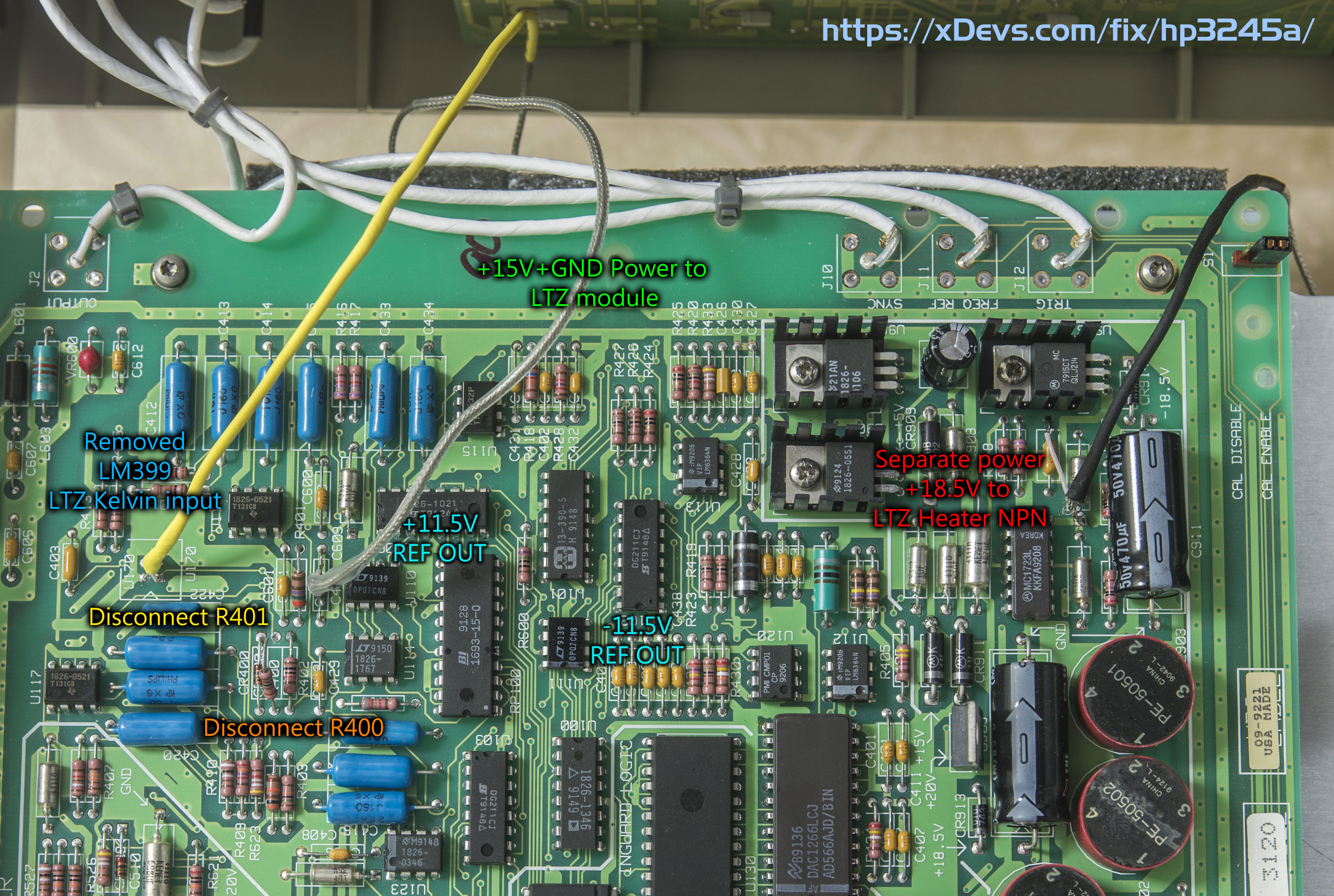
- Remove R400, R401, LM399 reference.
- Solder coax wire in place of LM399’s diode location. This connected to Kelvin output (direct connection at LTZ’s zener pins).
- Solder coax wire to +15V and GND to power LTZ’s opamps and control circuitry
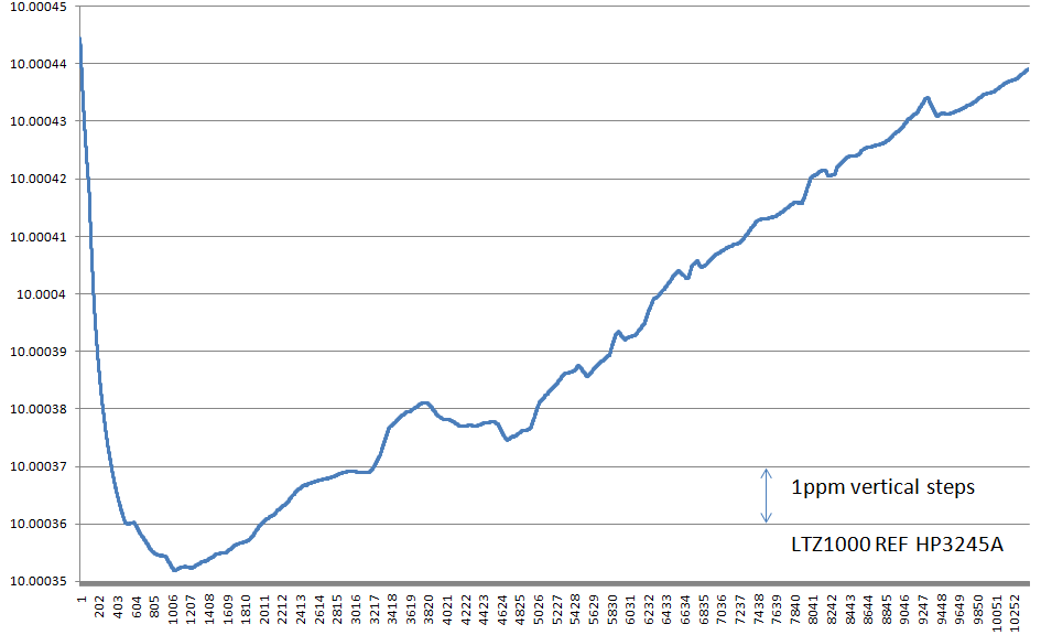
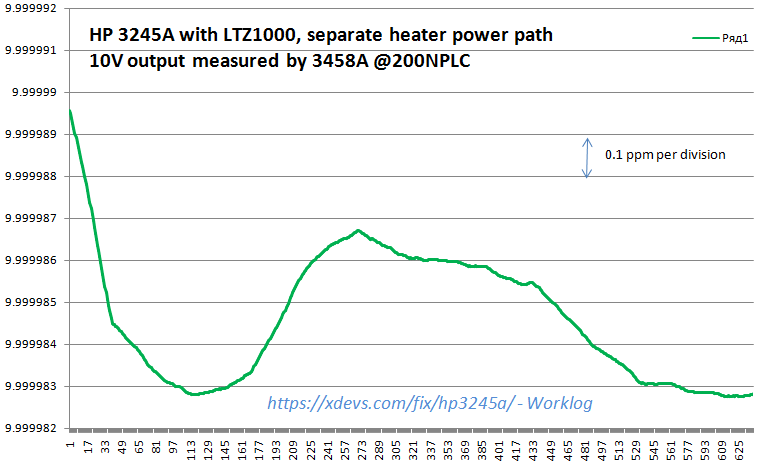
- Solder coax wire to +18.5V and power GND to provide separate current path for LTZ’s heater, so it would not upset reference output.
Last step is important, as heater current is big enough (~27mA) to raise ground those few ppm’s up, so output will get large error correlated to tempature, just like on graph below:
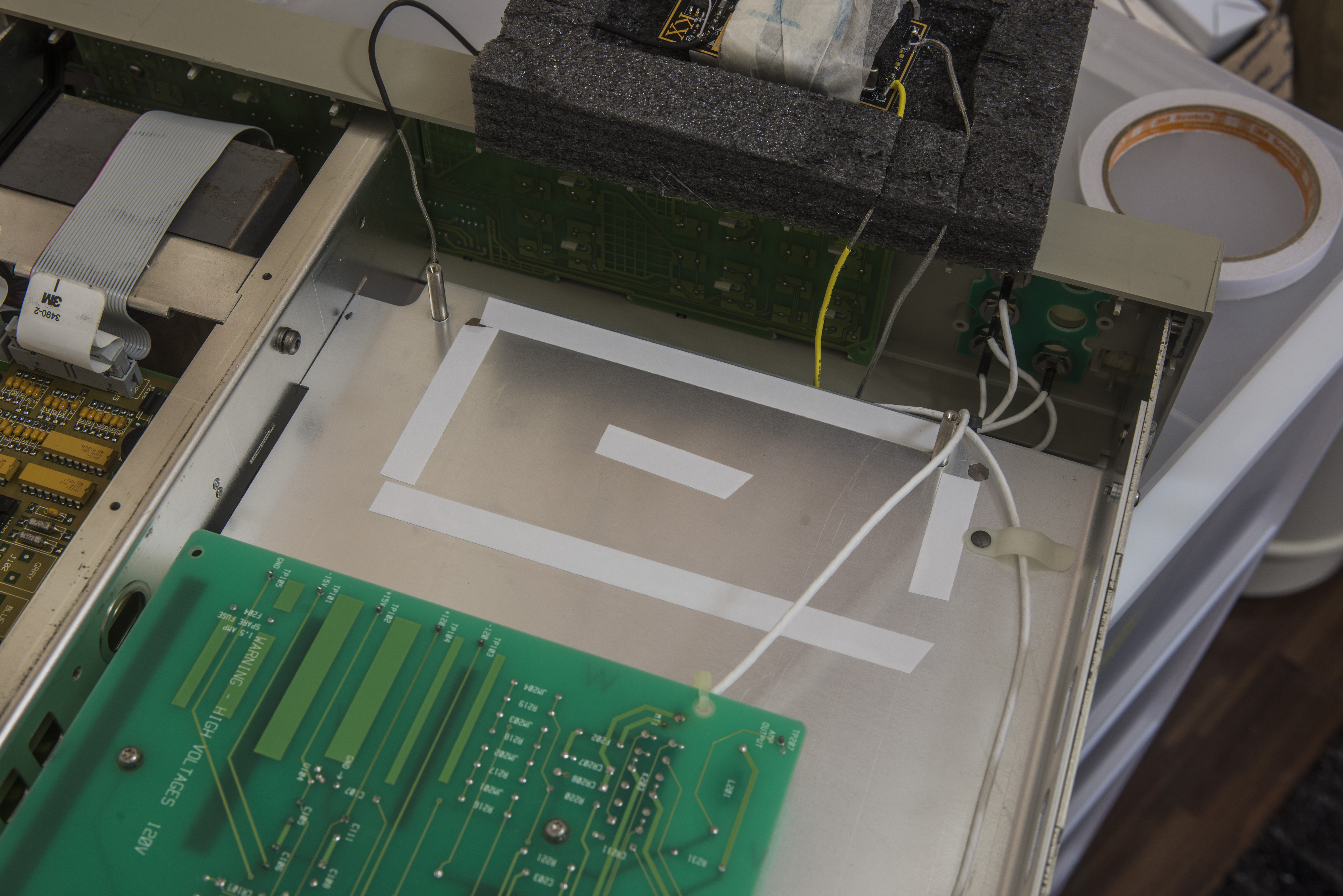
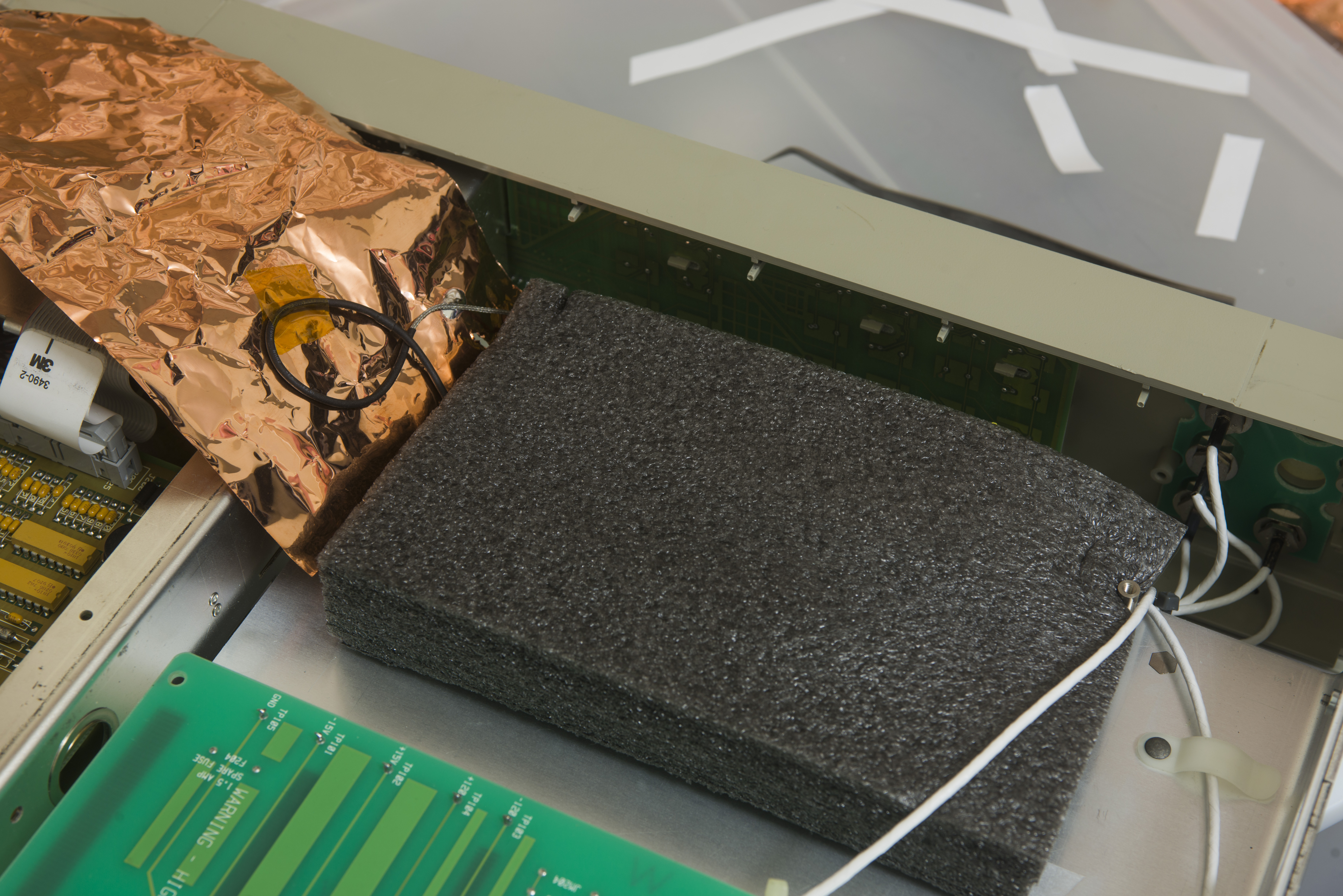
Now, find a best spot for module location. It’s likely to be between front panel and HV Opt.002 board. It’s far from mains transformer, and far from fan airflow. We want to keep all magnetic and temperature variations away from sensitive LTZ1000 reference. To have it isolated from airflow I added big piece of airlocked foam used in packing electronics.
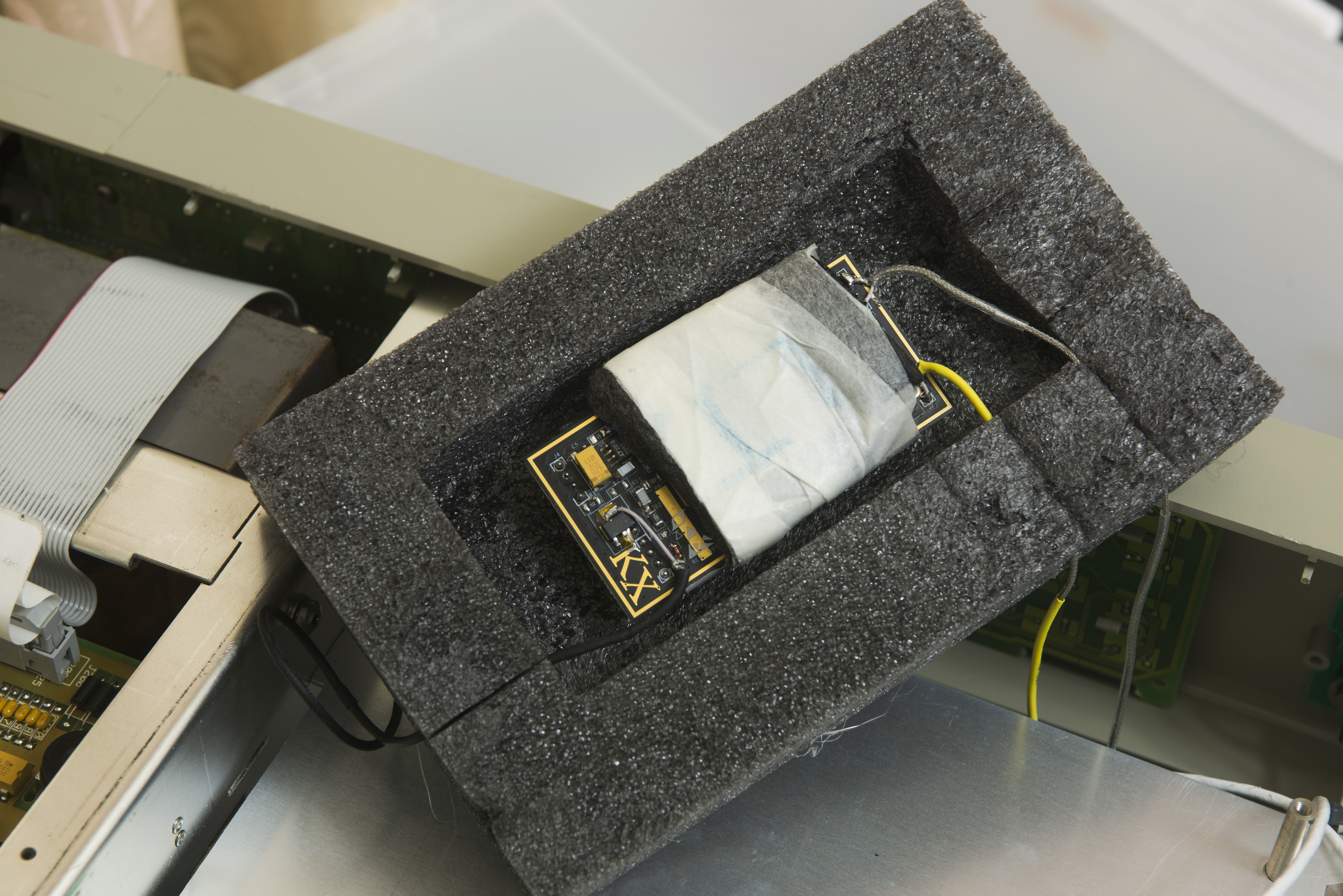
It tied to metal chassis via dual-sided 3M tape to keep seal tight.
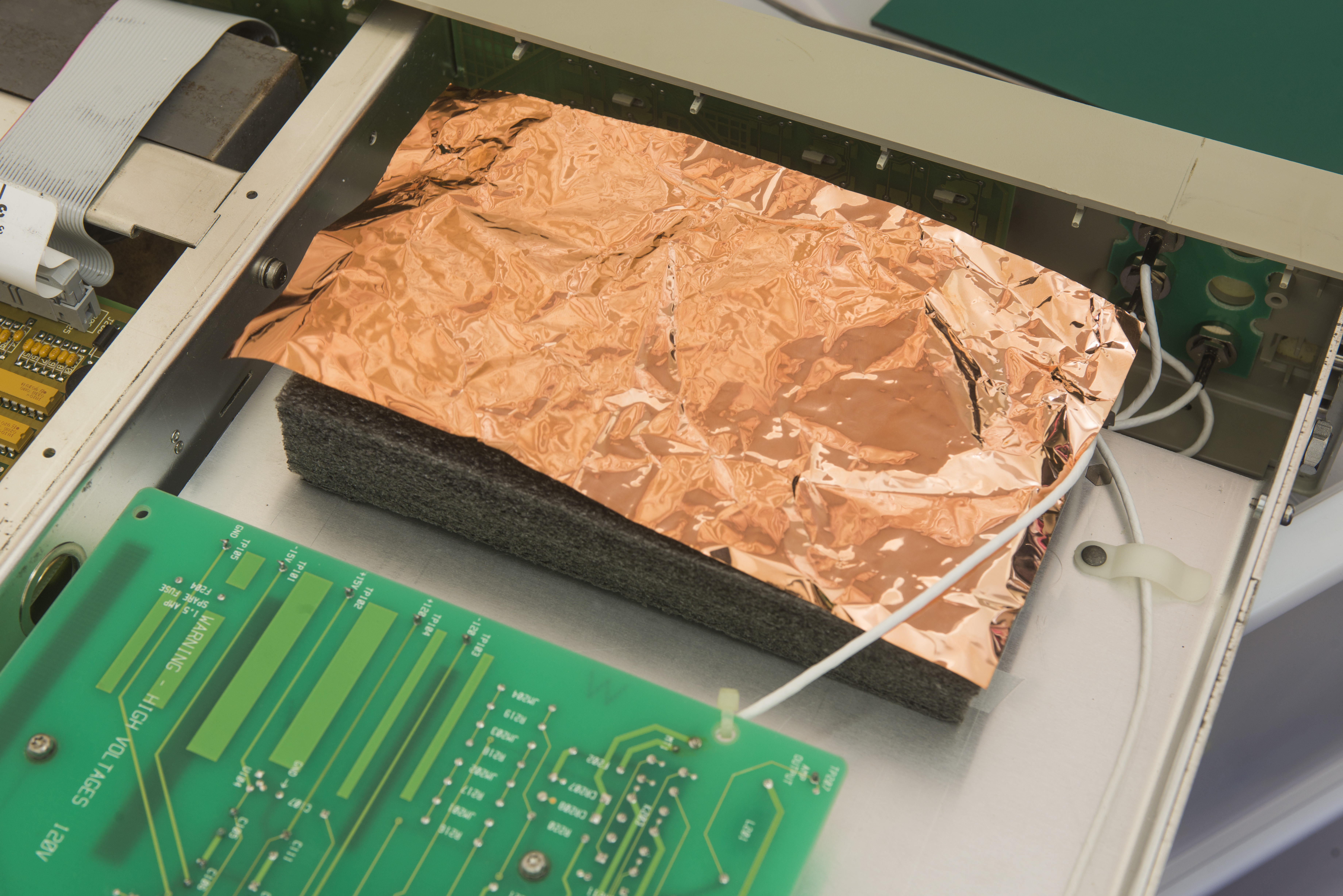
Copper foil soldered to ground on power coax wire is located on top. Idea to have it for better temperature distribution and bit of shielding.
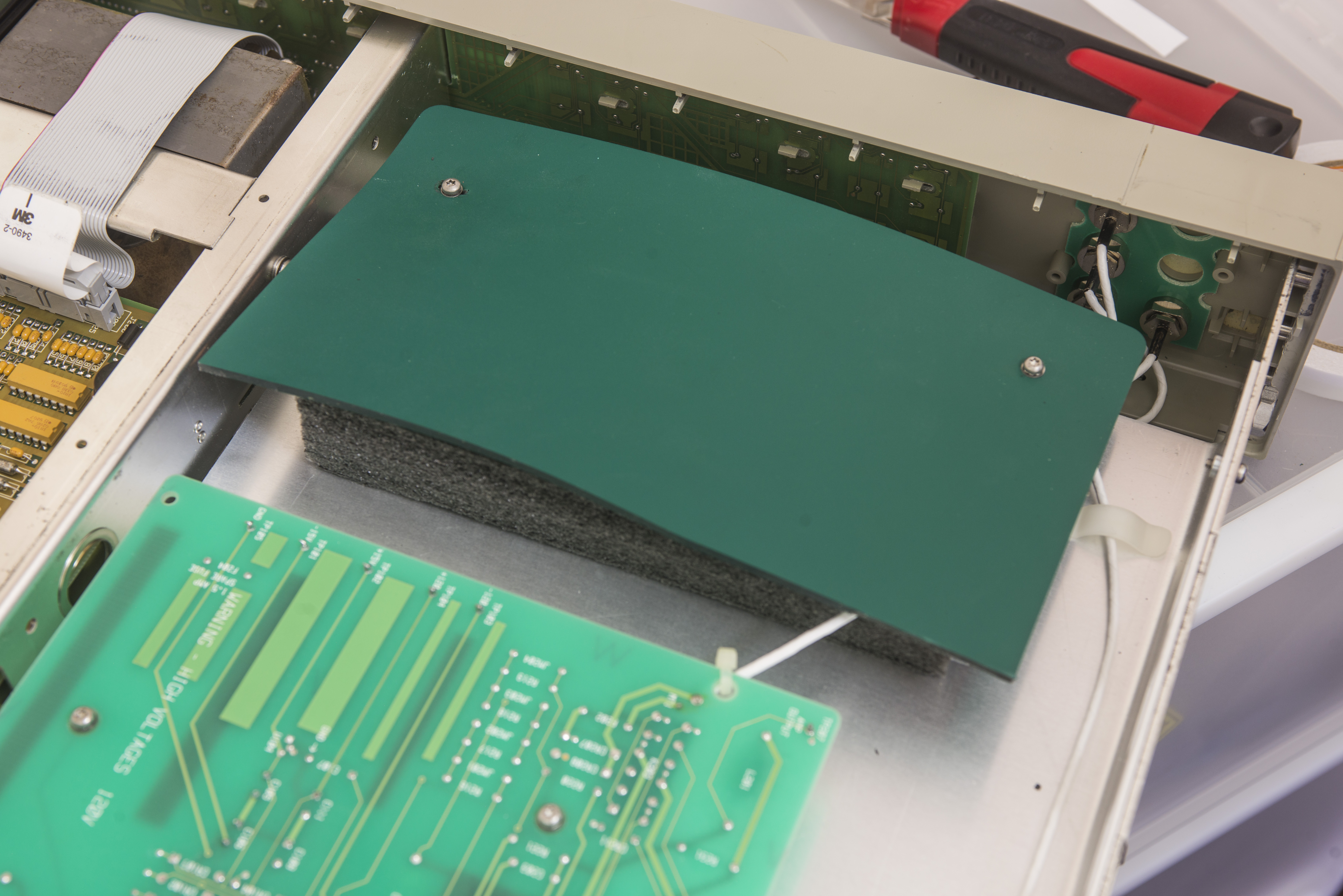

Piece of 4mm rubber pad is holding everything in place securely, screwed down to existing two metal stubs on chassis. Coax wires not touching anything and running at least 1cm from output wires/front panel.
Photo below shows assembly after modifications, both top:
And bottom side:
Calibration
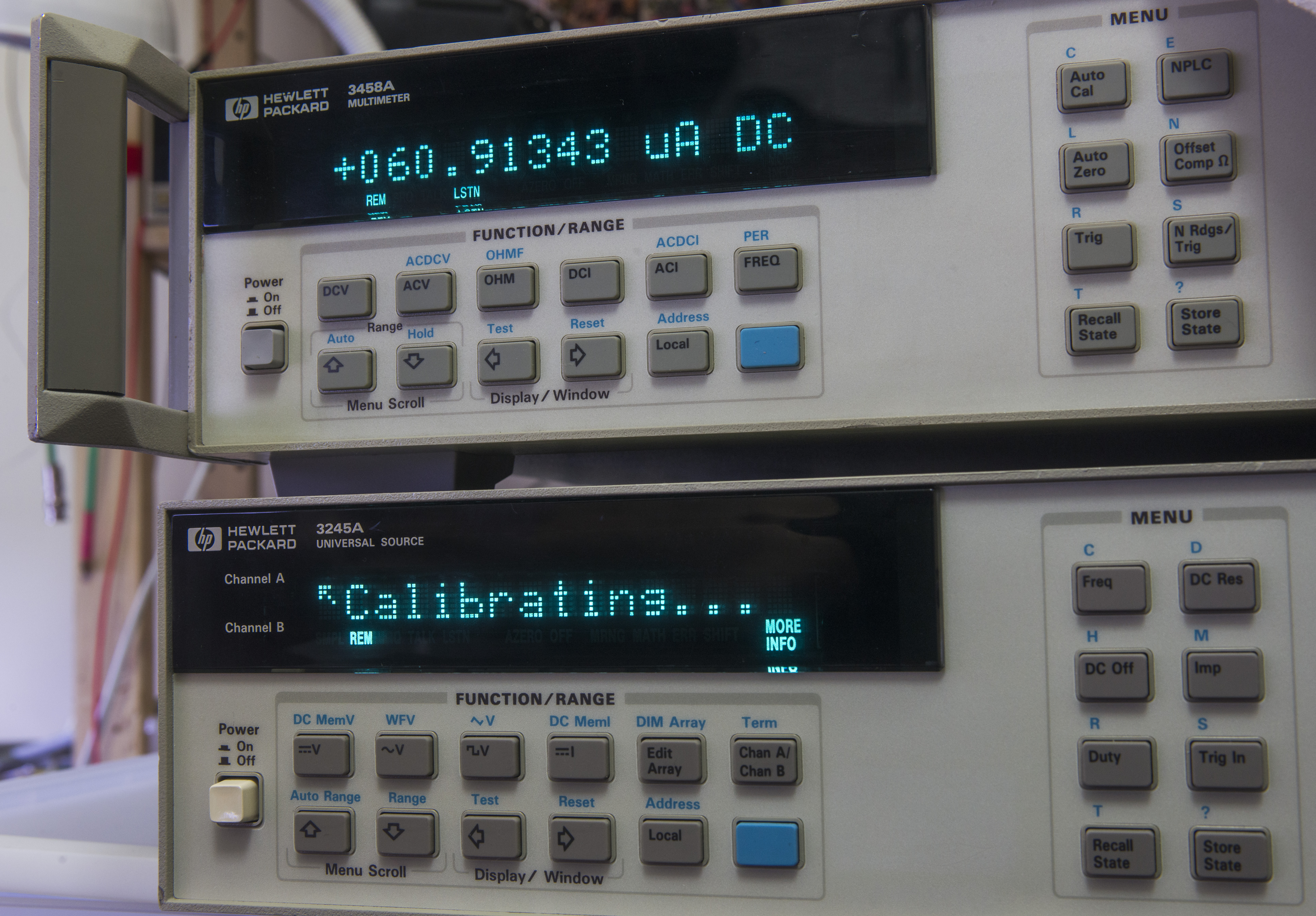
Let’s calibrate it. Due to different reference voltage output of new reference chip, previous calibration was useless, causing source to output 10.29VDC while 10.00VDC set.
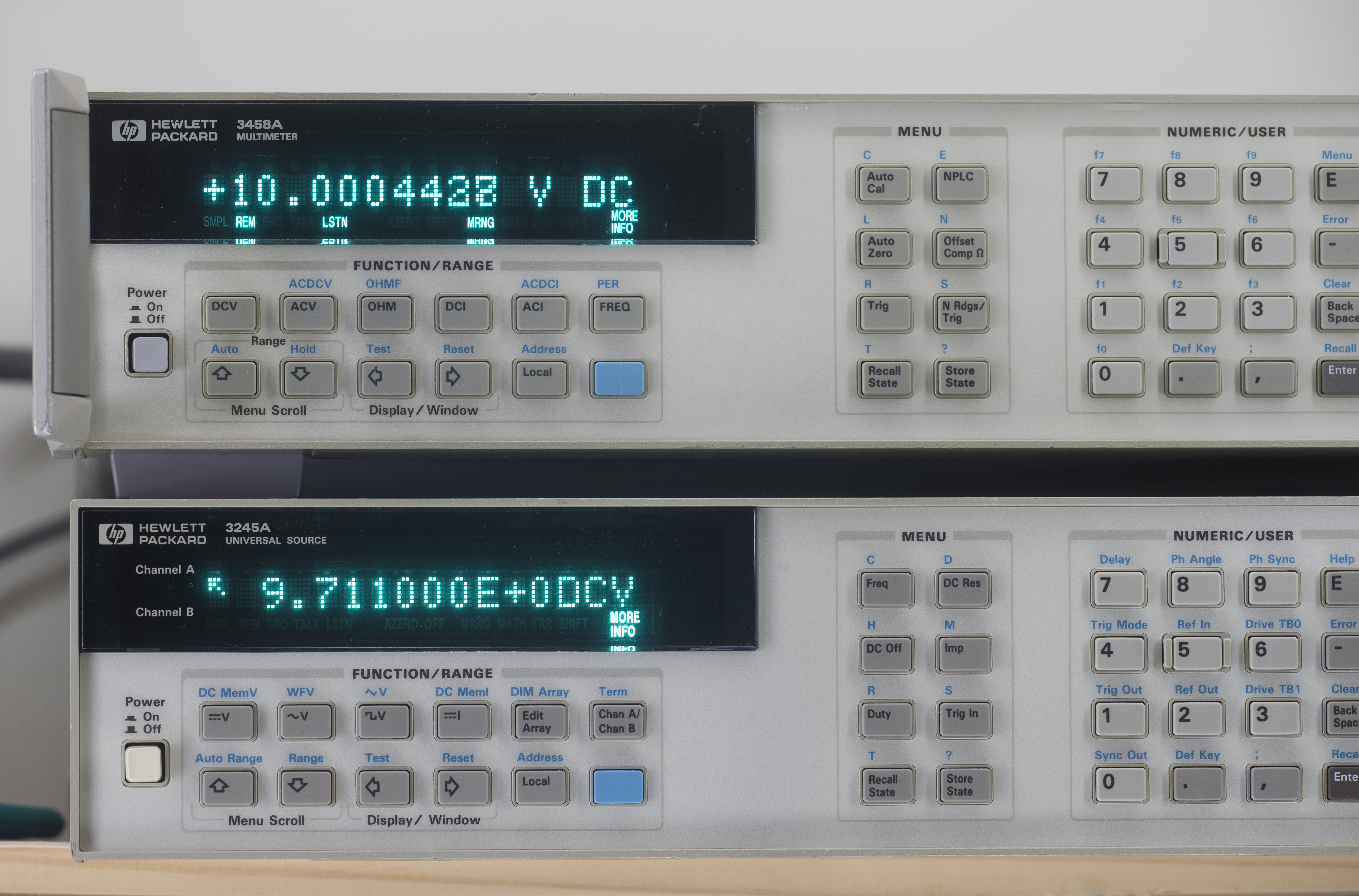
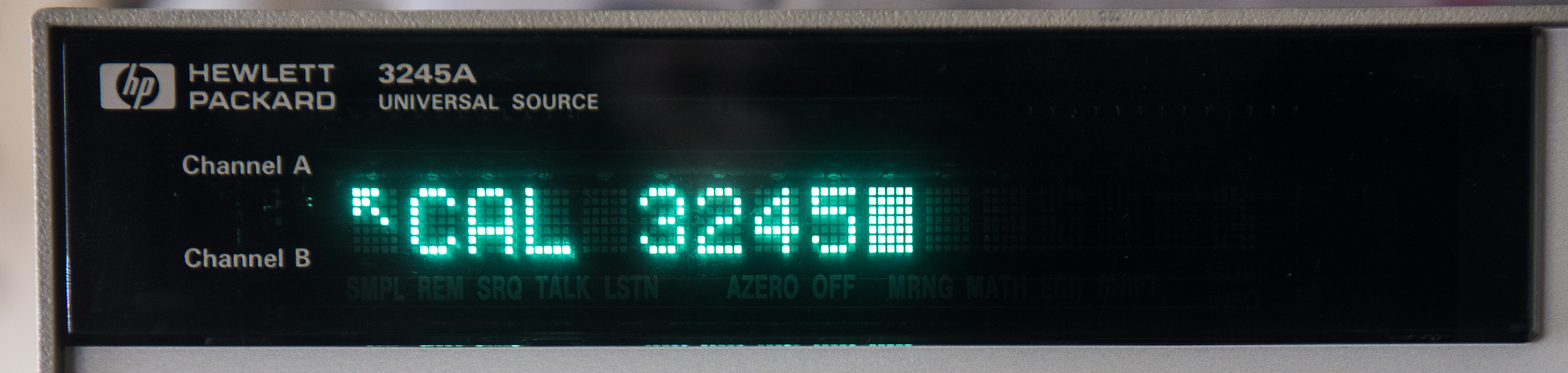
Calibration mode entered by execution of command CAL 3245.
Now source will output reference points according to calibration manual, and these need to measured by 3458A or similar level DMM, and sent back by GPIB command.
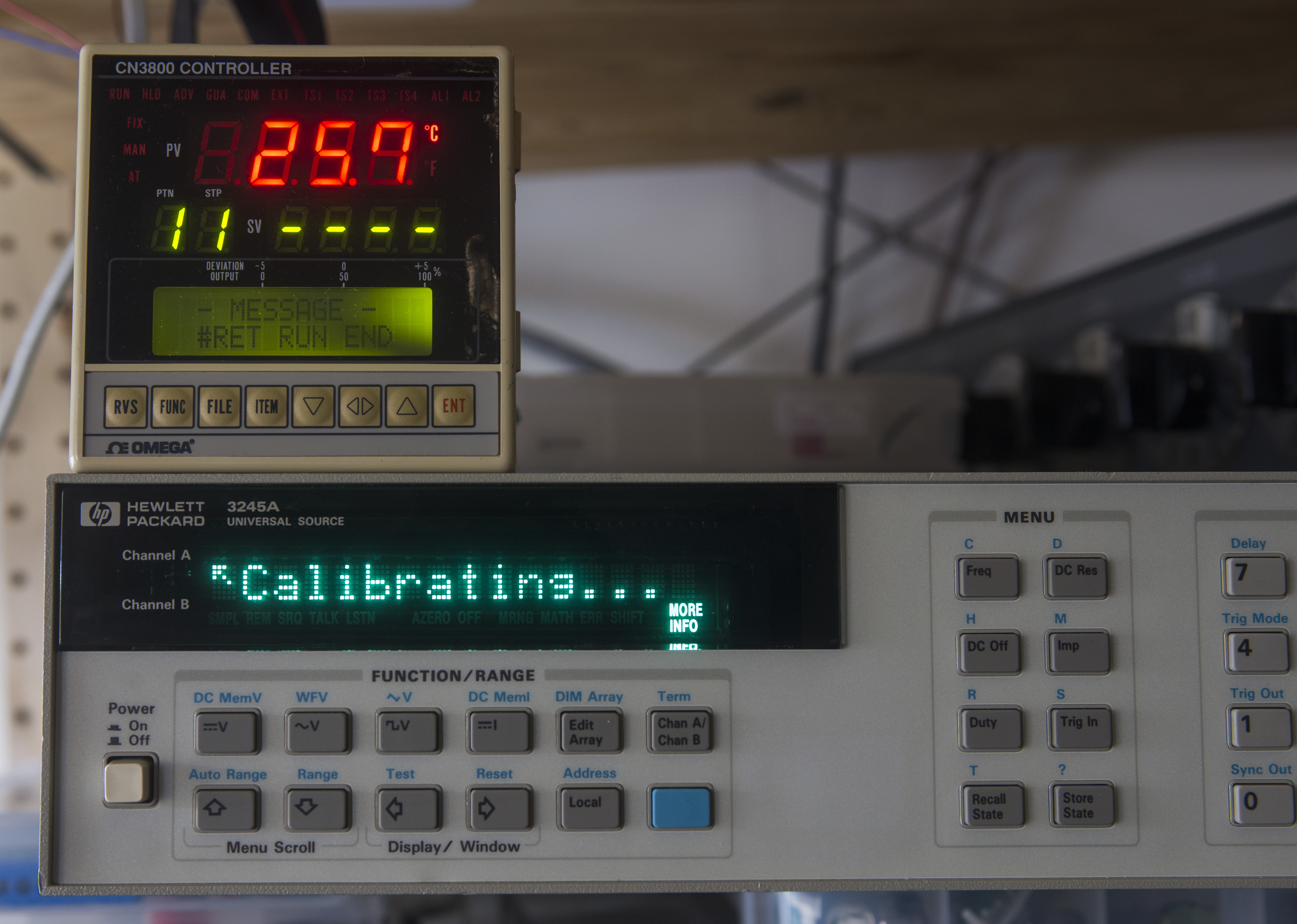
Temperature in room around +26°C. After entering calibration mode, it’s just showing “Calibrating…” and output have voltage or current, which need to be measured by DMM and written back by command “CAL VALUE x.xxxxxxxx”. After running all values from cal manual, it automatically saves CALRAM. Optionally you can leave a string with CALSTR “TEXT” later.
HP 3458A was ACAL’d and initial calibration was just quick sanity check, to make sure I can get output 10.000V. I did not have too much effort on it to do.
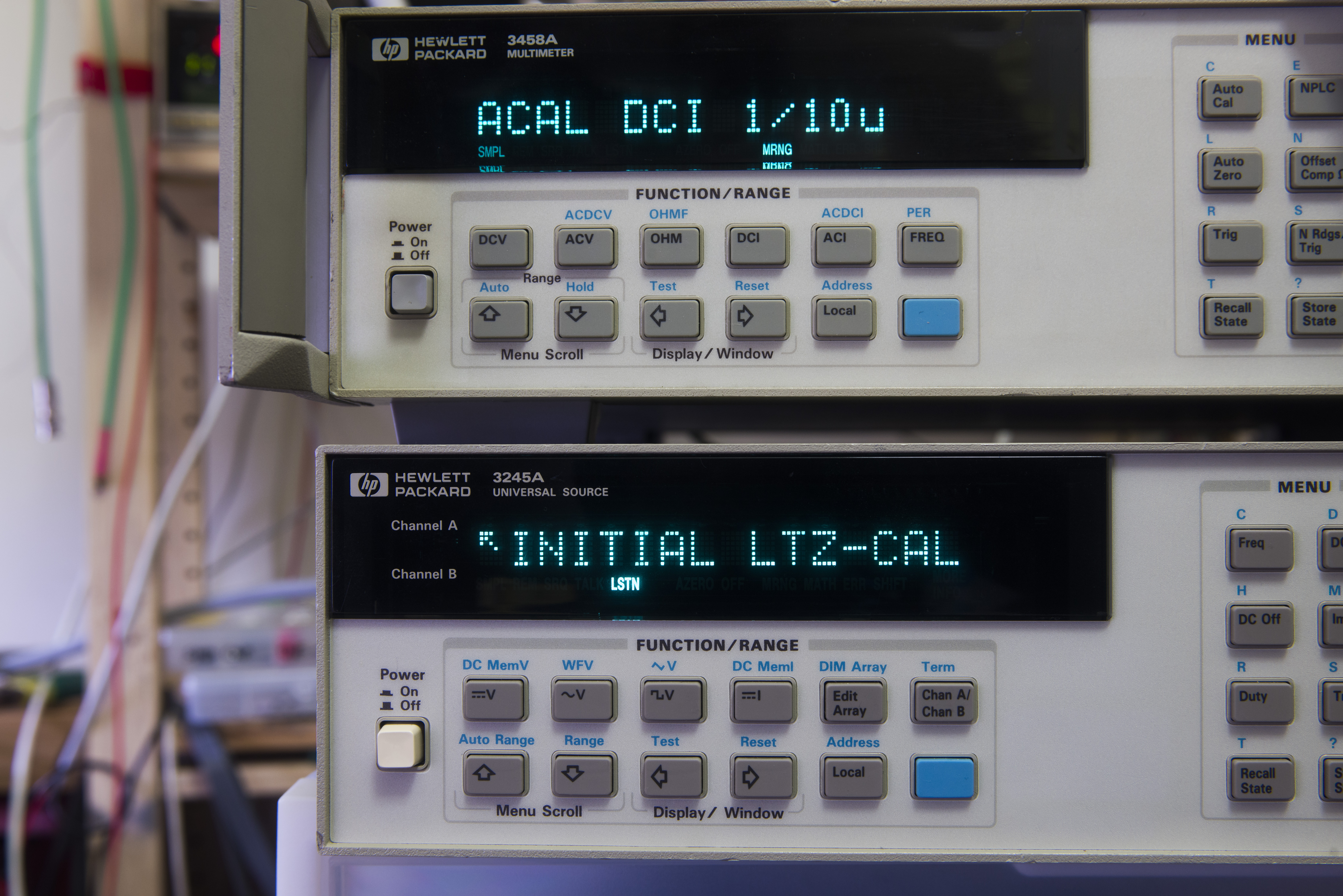
It worked well, so I calibrated again, keeping temperature within 1°C span and measuring all at NPLC200
To automate calibration with help of HP 3458A and Windows PC with GPIB controller, EEVblog member alanambrose developed a neat software kit that runs all calibration steps and performance verifications remotely. By using the software it takes just 15 minutes to adjust 3245A to 3458A calibration.
00:18:01 *** 3245A calibration v0.2 ***
00:18:01 user parameters are '/GPIB3245=2 /GPIB3458=3 /RUNCALIBRATION /TITLE=cal /CALTYPE=DCV'
00:18:01 *** Channel A ***
00:18:01 *** Connection attempt to 3245 on GPIB '2'... ***
00:18:01 SRC ID? HP3245
00:18:01 Found instrument 'HP3245' on GPIB address '2'
00:18:01 SRC RESET sent
00:18:01 SRC END ALWAYS sent
00:18:01 *** Connection attempt to 3458 on GPIB '3'... ***
00:18:02 DMM ID? HP3458A
00:18:02 Found instrument 'HP3458A' on GPIB address '3'
00:18:02 DMM RESET sent
00:18:02 DMM END ALWAYS sent
00:18:02 *** 3245 status ***
00:18:02 SRC REV? 2843
....
00:18:02 *** 3458 status ***
00:18:02 TEMP? 37.400000
00:18:03 LINE? 59.988819
...
00:18:03 *** smoke tests ***
00:18:03 SRC APPLY DCV 100E-02 sent
00:18:03 SRC DCRES HIGH sent
....
00:18:13 SRC CAL VOLTS 3245 sent
00:18:19 reading 1 is 9.716802625
00:18:20 CAL written
00:18:20 SRC CAL VALUE 9.716802625 sent
00:18:20 DMM RANGE AUTO sent
00:18:25 reading 2 is -9.685200573
00:18:27 CAL written
...
And result after calibration
Now I’ll leave it overnight without AC, to see how good is tempco.
I checked 3458A+EDC MV106 earlier today, outputting 10VDC. That setup had +1.23 ppm/°C tempco. I hope 3245A with LTZ + 3458A can be better.
Residual weak signals verification in DCV HIRES, 0 VDC source mode
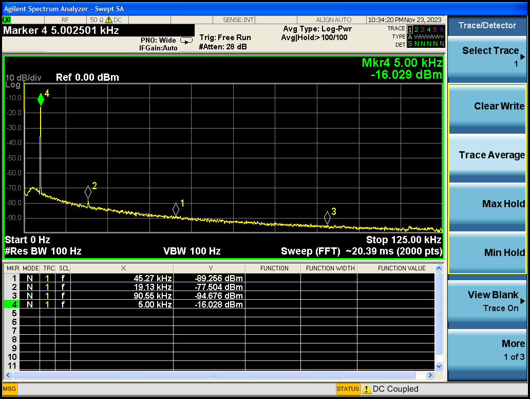
During one of NoisePath repair episodes TheSignalPath highlighted small but visible signal present when HP 3245A configured in DCV function with 0 V output. At first I thought it was some interference or noise pickup at first, but upon further investigation with signal analyzer presence of weak signal was confirmed on our unit and on the second 3245A.
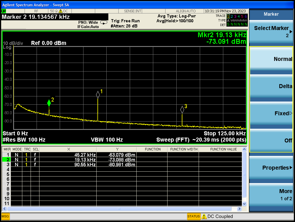
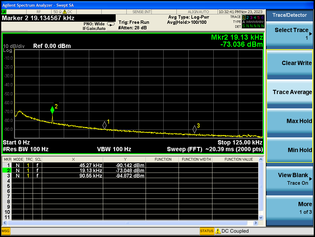
Strongest signal in my unit was measured at -63 dBm with frequency 45.27 kHz, with additional tone present at 19.13 kHz -73 dBm and 90.56 kHz -81 dBm. Measurement was captured using direct coaxial cable connection between source output port and Keysight N9020A MXA spectrum analyzer. If HP 3245A is configured to DCRES LOW (setting low resolution operation) then only 19.13 kHz tone remains and both 90.56 kHz and 45.27 kHz signals drop below the noise floor.
If HP 3245A configured in ACV mode, for example to output 0.05 Vpk-pk at 5000 Hz then larger parasitic signals are also absent, with only weak 19.13 kHz detect at -77.5 dBm power level.
Second 3245A (without any options) also had parasitic 70 kHz tone present at the output when configured on DCV 0 in HIRES.
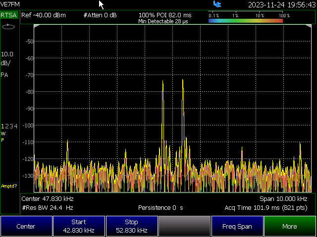
Our friend VE7FM also investigated his own HP 3245A (option 002) with his Keysight FieldFox N9918A spectrum analyzer.
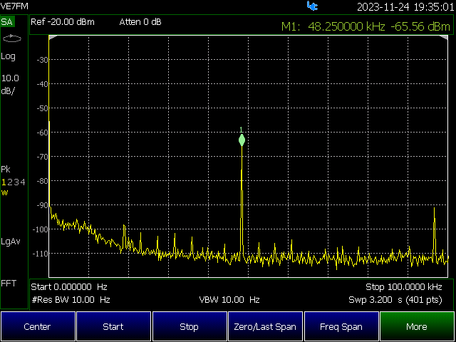
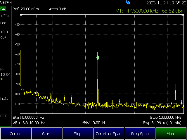
His analyzer detected tones at 48.25 kHz (channel A) and 47.5 kHz (channel B) present with similar power level around -66 dBm. With real-time analysis mode results repeated pretty well, with noise floor below -92 dBm.
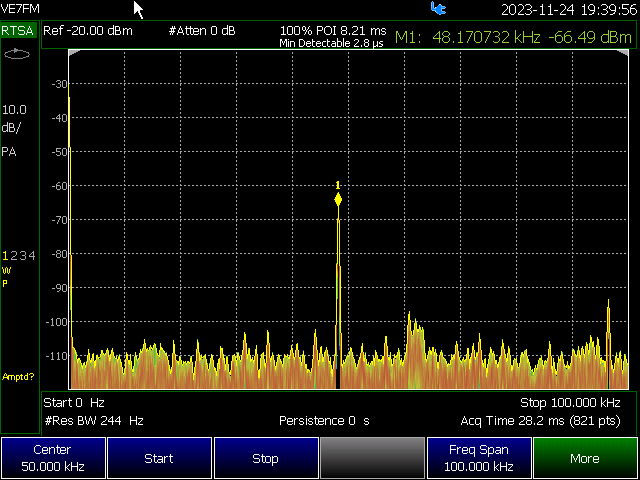
Screenshot with real-time spectrum and combined CH-A and CH-B signals for fun observation:
Based on this small investigation if application require only clean DC/low frequency signals perhaps it is worth to consider adding low-pass filter with cutoff frequency below 10 kHz at the output of HP 3245A.
Additional output amplifier for 0.1x/0.01x gain
There is free space in unit and few extra chassis mounting studs, which are just asking for extra stuff to be mounted. I have idea to make low-gain divider opamp board, so I could generate lower voltages more accurately, as high-resolution ranges are only 1V and 10V.
Perhaps output divided by 10 or even 100 would be great addition to unit. Front panel still have two BNC ports, so it is possible to have clean and nice looking modification.
Restoration summary
| Item | Cost | Shipping |
|---|---|---|
| Faulty HP 3245A with Opt.002 | 343$ | 175$ |
Total repair cost in parts as for today: $518 USD
| Date | Actions | Time spent |
|---|---|---|
| 11/3/2015 | Received unit, initial teardown | 1 hour |
| 11/13/2015 | Install LTZ1000ACH reference module | 3 hour |
| Taking photos, writing up article sections and posts | 3 hours |
Total time spent on this project around 7 hours, give or take few.
Equipment used during restoration project:
- Soldering gear, ERSA I-CON station, 3M copper wick to remove solder & capacitors, PbSn solder
- 0.1L of IPA and alcohol to clean chassis and parts
- MiniPro TL866CS programmer to read/write ROMs/RAMs
- Keithley 2001 DMM (calibration 02/2014)
- HP 3458A 8½-digit DMM (calibrated against Keithley 2001)
- Nikon D3 for time-lapse shooting
- Nikon D800 with 28-70/2.8D, Sigma 150/2.8 Macro, 35/1.8G DX lenses, tripod
- Google – used lots of it!
Easter egg
Same as 3458A, this instrument does have easter egg, which can be discovered by sending GPIB command XYZZY ;)
Modified: Nov. 25, 2023, 4:54 a.m.