Contents
- Intro
- Specification
- Disclaimer
- Initial inspection and basic disassembly
- Manuals references
- Repair workflow
- Chassis repair
- Diagnostics
- Repair for HARDWARE FAILURE — SLAVE TEST: CONVERGENCE
- Repair for DCI ranges 100nA, 1µA, 10µA, 100µA
- Repair for SYSTEM ERROR 114 — multislope rundown convergence
- Repair for ERROR 204: Hardware Failure: Level DAC Convergence
- Repair for A/D drift
- Repair for A/D drift, ADC A3 replacement
- Firmware
- Other possible 3458A issues, reported by community
- Tweaks and tricks
- Adding extra memory option
- Improving long-term stability of LTZ1000A voltage reference module
- Improving long-term stability for resistance measurement
- Improving long-term stability for current measurement
- Disabling VFD to save it’s life during remote operation
- Swerleins Algorithm for improved low-frequency ACV measurement
- Calibration
- Performance verification
- Remote GPIB control article – article link
- Restoration summary
Intro
Hewlett-Packard was a big name in 20th century for electronics and test equipment. They designed and manufactured many equipment which works and not too shady even by modern standards today, 25 years after. Later, in 1999 HP’s Test and Measurement Division spun off into Agilent. Today electronics test instrumentation part become further split and is known by brand Keysight Technologies.
One of spectacular instruments which survived thru decades and three brands is metrology-grade 8½-digit Model 3458A multimeter, with its famous ultra-linear ADC. This meter is still selling and supported on market, with brand new cost reaching over $9500 USD, in base configuration. It was introduced back in 1989 with MSRP $6000 USD.
For those who are not familiar with 3458A, some very useful operation details and features are covered in this HP Journal 1989, dedicated for 3458A release. Journal sourced from HP Labs journal archive.
3458A have so impressive performance, that even competitors took it as platform, such as improved FLUKE HP 3458A/HFL Special Laboratory Digital Multimeter variant, prior to their acquisition of Wavetek Datron in 2000 and release of their own long-scale 8½-digit DMM, Fluke 8508A. Fluke HP3458A/HFL was only available from local Fluke representatives, and had specified for 0.01ppm ADC RMS noise.
But today we will look on old unit, still wearing HP logo, manufactured somewhat in 1996. It was purchased as “parts, non-functional” piece for $750 USD, which is below market price, even for broken meters. Perhaps you thinking “this guy is nuts, paying that money for 20 year old broken machine”. But think for a second, metrology-grade instrumentation market is very conservative. There are only few 8½-digit DMM models in the world, all vendors combined. So one may consider this project as deposit investment, given that instrument can be repaired and brought back to full specifications.
Here’s a complete list 8½-digit long-scale meters:
| Manufacturer | Model | Type | Status |
|---|---|---|---|
| Advantest/ADCMT | R6581D | DMM | Obsolete |
| ADCMT | 7480T | DVM,Ohms | Part of automated test systems |
| Additel | 286 | DMM/datalogger | Current model |
| Datron | 1281/1271 | DMM | Obsolete |
| HP/Agilent/Keysight | 3458A (+Fluke HFL version) | DMM | Obsolete |
| Keysight | 3458A Black | DMM | New model |
| Fluke | 8508A | DMM | Obsolete |
| Fluke | 8558A | DMM | New model, low cost version |
| Fluke | 8588A | DMM | New model, metrology grade DMM |
| Keithley | 2002 | DMM | Current model |
| PREMA | 6048 | DMM | No longer available for sale |
| Solartron | 7081 | DMM | Also known as Guildline 9578. No longer available for sale |
| Transmille | 8080 | DMM | Obsolete |
| Transmille | 8081 | DMM/Electrometer | Obsolete |
| Transmille | 8104 | DMM/Electrometer | Current model |
| Transmille | 8881 | DMM | ? |
| ZIP Nauchpribor KM300 | KM300 | DCV/Res/DMM/Calibrator |
Table 1: 8½-digit DMMs
It does take tremendous amount of time and effort to test, validate and prove stability and performance of such machines, where no detail is insignificant. Performance is a key point of these designs, and even now many engineers trust their measurements from 3458A’s. Old, but not obsolete. Hope this giving you idea how much it can go as today, even for broken meter with unknown condition, and why is it so. It’s also troublesome for international shipping, with weight about 15kg and large size (~2U height with full-size 19” rack depth and width).
Let’s see what we have to do to get unit back to operational state. My plan for this project is to perform full component level repair, and perform overall study of instrument’s internal construction, as repair advances. This means we will not be doing expensive boards swap unless absolutely unavoidable.
As usual, all photos are clickable for high-resolution version.
Recently many threads pop up, with question “Is it worth to buy 3458A for XXXX$?. Well, simple answer is – No, it’s a big risk. If you asking yourself about this, then you are not ready for it. Buying broken or used 3458A for “good price” and fixing it might not be an easy way of getting good 8½ DMM, when multiple hidden costs considered. If unit stated as “untested/unknown/don’t know how to test” and not to have shown self-test result, it could have hardware failures. Paid cost for such a unit WITH proper repair can easily exceed cost of buying a fully tested unit. If unit’s photo shows it as powered up but you can see “ERR” on display, it also means there is fault detected. Keysight have standard 3458A repair + recalibration cost at $2660 USD. Calibration alone of fully functional unit is likely to be over $1000 USD. Also old units manufactured earlier than 2005, would have Dallas NVRAM batteries already near end of life, with risk of losing calibration data any day. So even if you buy meter for 1000$, you can be easily be held back by 2000-3000$ more to fix it and get calibrated.
There are also special versions of 3458A with options, such as:
| Option | Description |
|---|---|
| 3458A-001 | Extended memory option |
| 3458A-002 | Improved DC reference stability 4 ppm/year |
| 3458A-H01 | Special 1000 Vrms ac maximum input voltage |
| 3458A-H52 | US Air Force NSN |
| 3458A-HFL | Fluke version 3458A/HFL with 2ppm/year stability and better resistance |
| 3458A-E02 | Special version |
| 3458A-OGC | Precision calibration, intended for metrology use only |
Table 2: 3458A options and versions
Here are details how to determined installed options in your specific unit (besides looking at option labels/stickers):
Option 001 (extended memory – this option can be bought by ordering kit 03458-87901)
Meters containing Option 001 will return a 1,0 when queried with an OPT? command, either from front panel or GPIB.
- The A5 assembly has memory IC’s: U122, U123, U124 and U125 (the standard instrument has empty sockets in the locations for the above IC’s).
- If the initial 3458A order included Option 001, the A5 assembly will be labeled 03458-66515 or 03458-69515 (the A5 assembly in a standard unit will be 03458-66505 or 03458-69505).
Option 002 (high stability 4ppm/year reference – this option can be bought by ordering kit 03458-80003, around $1K USD)
- The A9 assembly is labeled 03458-66519 (the A9 assembly in a standard unit is labeled 03458-66509).
Option H01 (1000 Volt ACV measurement capability – Standard unit is limited to 700 Volt ACV).
- The A1 assembly is labeled 03458-91002 (the A1 assembly in a standard unit is labeled 03458-66501 or 03458-69501).
- The A2 assembly is labeled 03458-91000 (the A2 assembly in a standard unit is labeled 03458-66502 or 03458-69502).
- The A10 assembly is labeled 03458-91001 (the A10 assembly in a standard unit is labeled 03458-66510).
HFL 2ppm/year stability reference option, standard option for Fluke/HP 3458A-HFL version.
- The A9 assembly is labeled 03458-66529 (the A9 assembly in a standard unit is labeled 03458-66509).
Specification
Brief specification for HPAK 3458A-002 listed in table below. More detailed specifications can be found in Appendix A of User’s Guide
| Function | Range | ||||||||
| DC Voltage | 100mV | 1 V | 10 V | 100V | 1000 V | ||||
|---|---|---|---|---|---|---|---|---|---|
| Accuracy (1y), Rdg ppm + Range ppm | 5+3 (0.0005%) | 4+0.3 (0.0004%) | 4+0.05 (0.0004%) | 6+0.3 | 6+0.1 | ||||
| Temperature coefficient, ppm | 1.2+1 | 1.2+0.1 | 0.5+0.01 | 2+0.4 | 2+0.04 | ||||
| RMS noise at NPLC100, Range ppm | 0.2 | 0.02 | 0.01 | 0.02 | 0.01 | ||||
| AC Voltage | 10mV | 100mV | 1V | 10 V | 100V | 1000 V | |||
| Best accuracy (1y), Rdg ppm + Range ppm | 200+110 (0.02%) | 70+20 (0.007%) | 200+20 (0.02%) | 400+20 (0.04%) | |||||
| Temperature coefficient, ppm | 30+200 | 25+1 | |||||||
| Bandwidth frequency (max accuracy) | 1 Hz to 10MHz (40Hz to 1kHz) | ||||||||
| Resistance 4W | 10 Ω | 100 Ω | 1 KΩ | 10 KΩ | 100 KΩ | 1 MΩ | 10 MΩ | 100 MΩ | 1 GΩ |
| Accuracy (1y), Rdg ppm + Range ppm | 15+5 | 12+5 (0.0012%) | 10+0.5 (0.0010%) | 15+2 | 50+10 | 500+10 (0.05%) | 5000+10 (0.5%) | ||
| Temperature coefficient, ppm | 3+1 | 3+1 | 3+0.1 | 3+1 | 20+20 | 100+20 | 1000+20 | ||
| RMS noise at NPLC100, Range ppm | 0.3 | 0.3 | 0.03 | 0.045 | 0.06 | 3.6 | 36 | ||
| DC Current | 100 nA | 1 µA | 10 µA | 100 µA | 1 mA | 10 mA | 100 mA | 1 A | |
| Accuracy (1y), Rdg ppm + Range ppm | 30 + 400 | 20+40 | 20+10 | 20+8 | 20+5 | 20+5 | 35+5 | 110+10 | |
| Temperature coefficient, ppm | 10+200 | 2+20 | 10+4 | 10+3 | 10+2 | 10+2 | 25+2 | 25+3 | |
| Shunt resistance (burden voltage) | 545.2kΩ(55mV) | 45.2kΩ(45mV) | 5.2kΩ(55mV) | 720 Ω(75mV) | 100 Ω(100mV) | 10 Ω(100mV) | 1 Ω(250mV) | 0.1 Ω (<1.5V) | |
| RMS noise at NPLC100, Range ppm | 2.5 | 0.25 | 0.025 | 0.025 | 0.025 | 0.025 | 0.025 | 0.025 | |
| AC Current | 100 µA | 1 mA | 10 mA | 100 mA | 1 A | ||||
| Accuracy (1y), Rdg ppm + Range ppm | 600+300 | 600+200 | 600+200 | 600+200 | 800+200 | ||||
| Temperature coefficient, ppm | 20 | ||||||||
Table 2b: 3458A key specifications
Disclaimer
Redistribution and use of this article or any images or files referenced in it, in source and binary forms, with or without modification, are permitted provided that the following conditions are met:
- Redistributions of article must retain the above copyright notice, this list of conditions, link to this page (/fix/hp3458a/) and the following disclaimer.
- Redistributions of files in binary form must reproduce the above copyright notice, this list of conditions, link to this page (/fix/hp3458a/), and the following disclaimer in the documentation and/or other materials provided with the distribution, for example Readme file.
All information posted here is hosted just for education purposes and provided AS IS. In no event shall the author, xDevs.com site, or any other 3rd party, including HP/Agilent/Keysight be liable for any special, direct, indirect, or consequential damages or any damages whatsoever resulting from loss of use, data or profits, whether in an action of contract, negligence or other tortuous action, arising out of or in connection with the use or performance of information published here.
If you willing to contribute or add your experience regarding HP/Agilent/Keysight instruments repairs or provide extra information, you can do so following these simple instructions
Initial inspection and basic disassembly
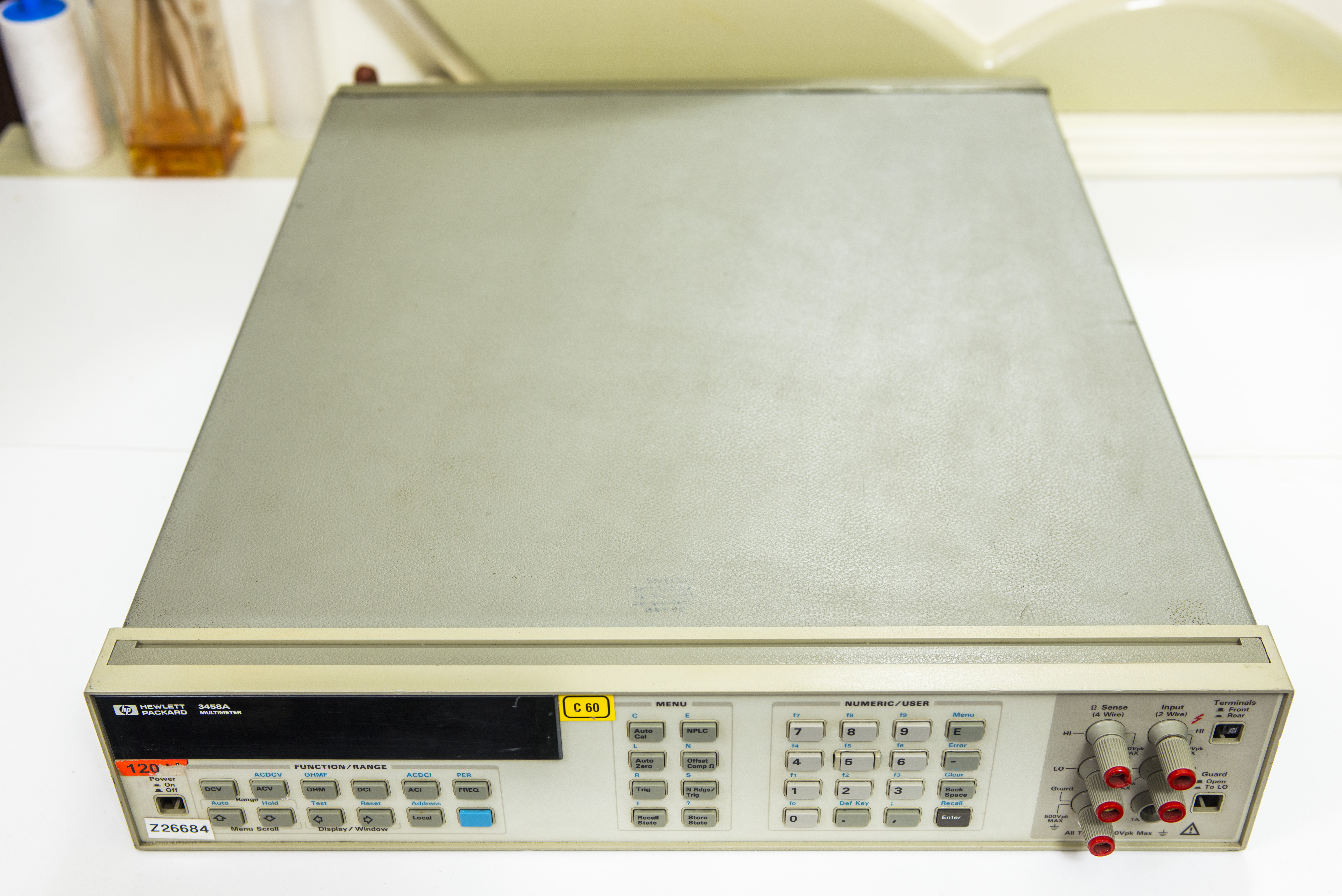
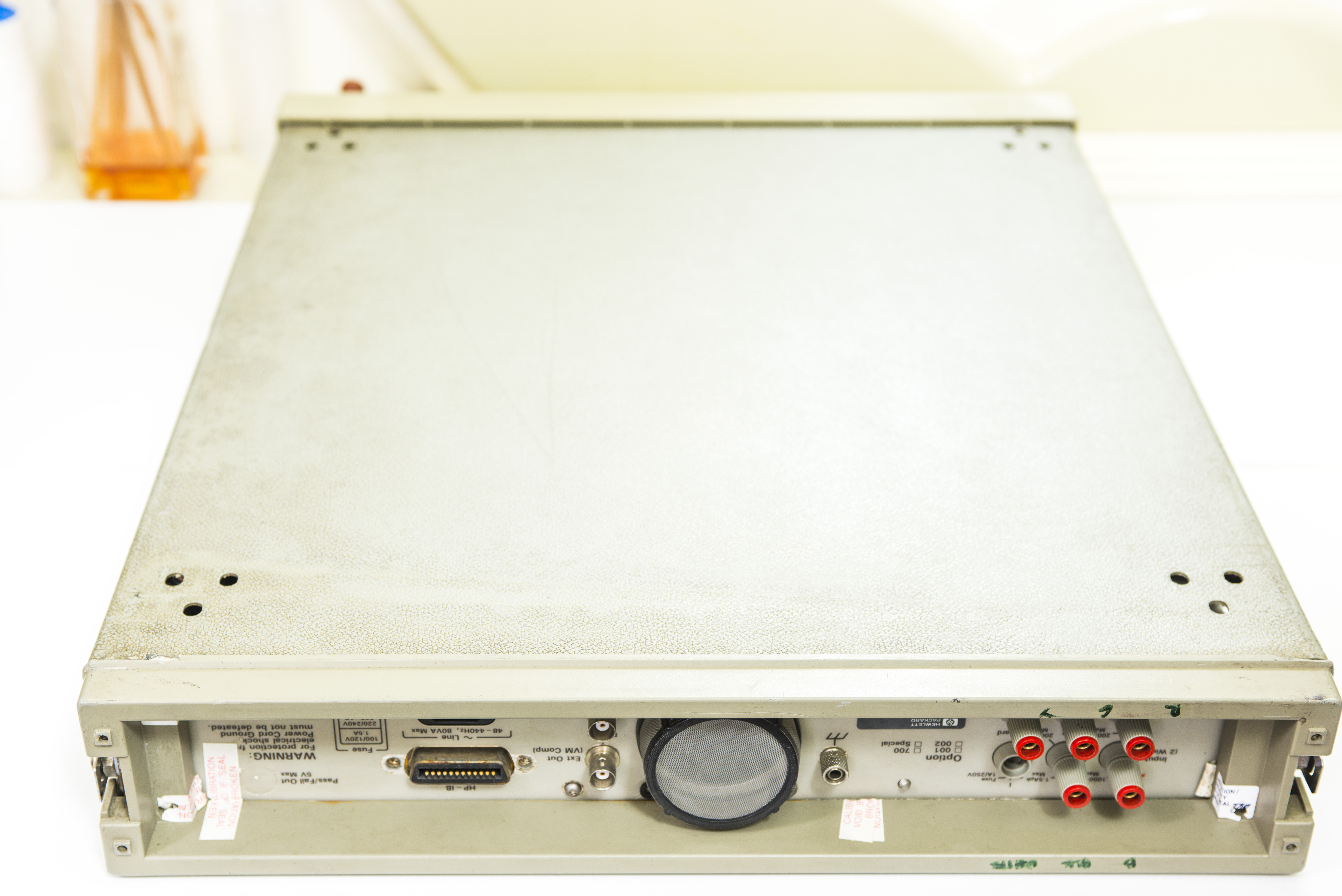
Image 1,2: HP 3458A front and rear faces
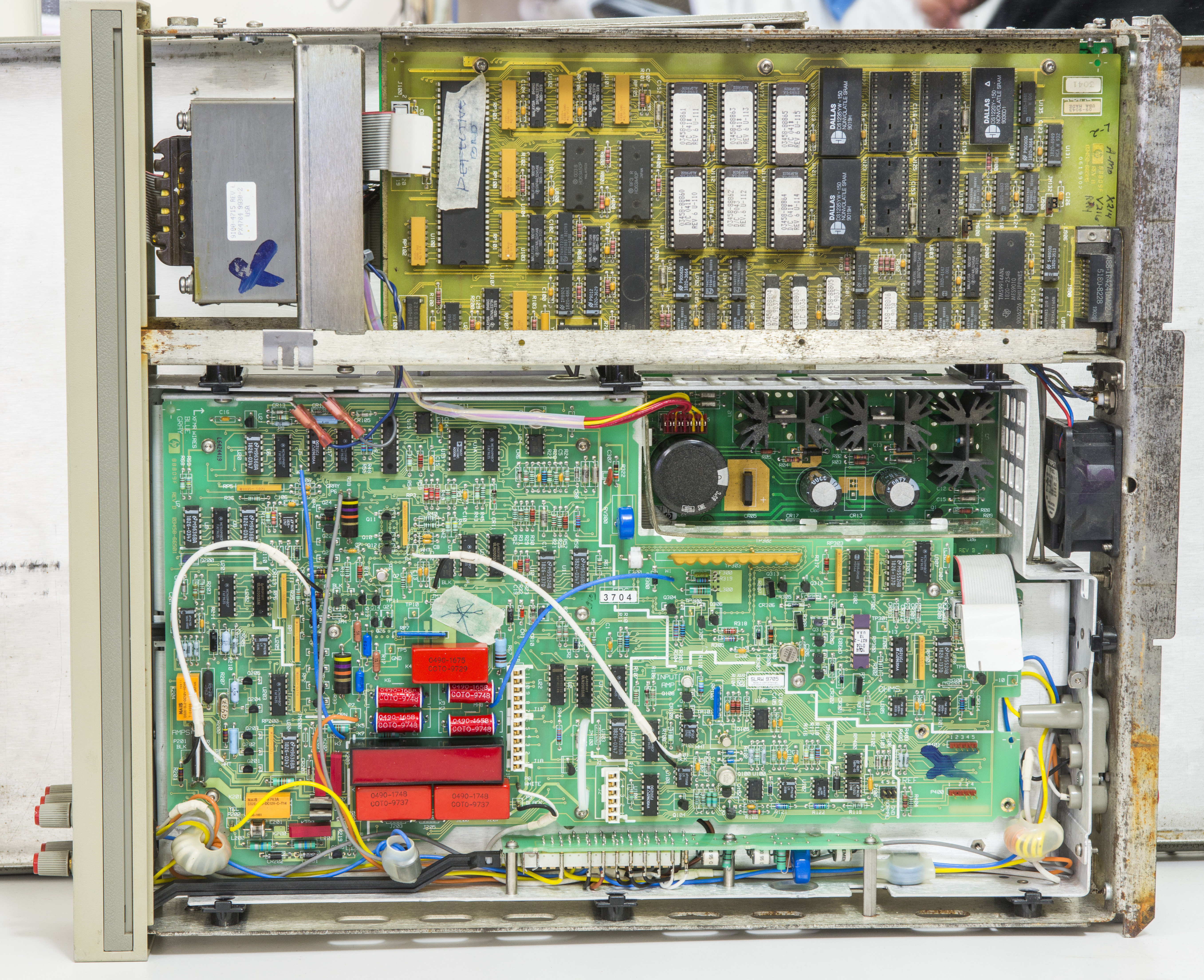
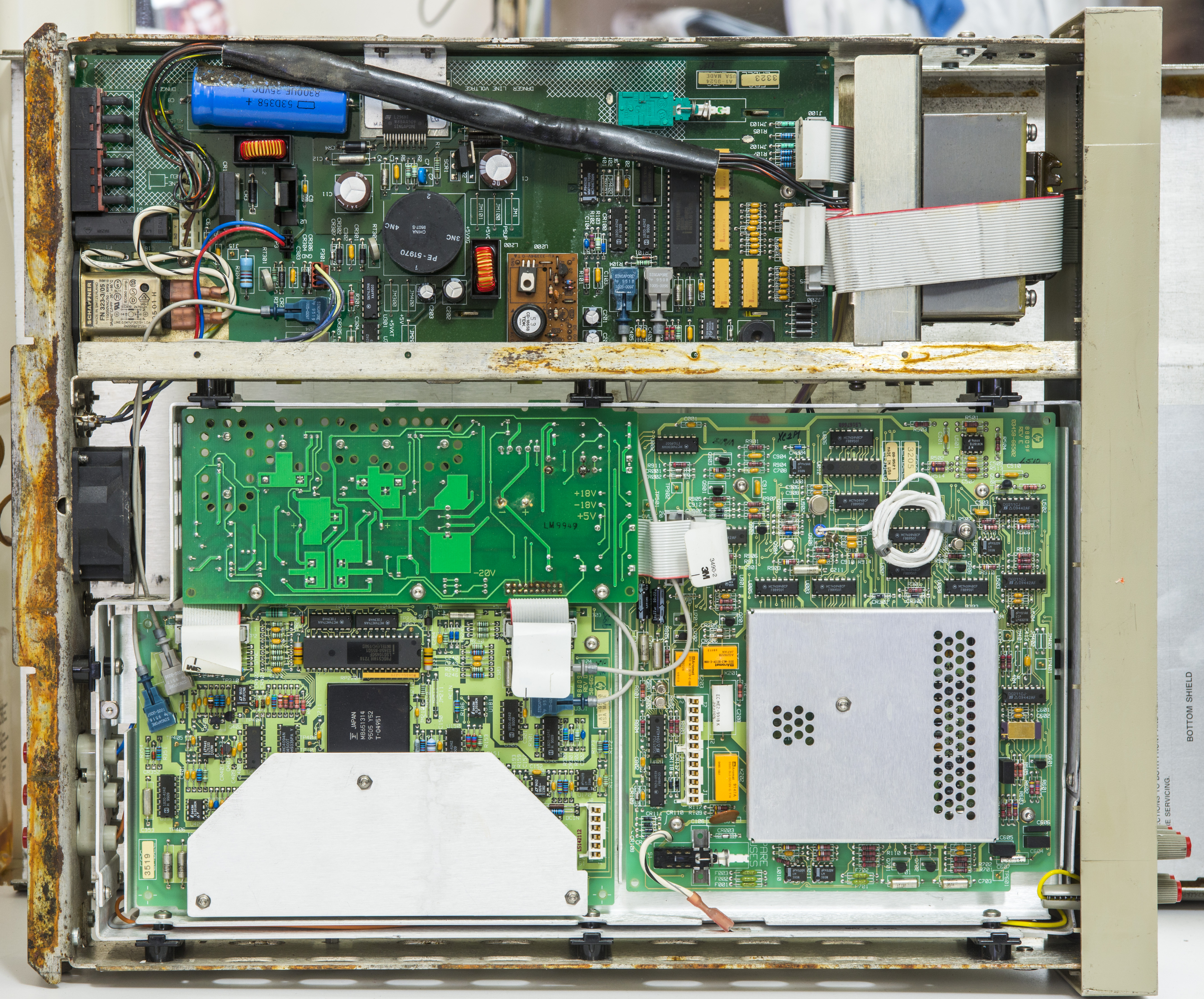
Image 3,4: HP 3458A top and bottom sides, without covers
Damaged parts (and current status):
- U100 processor MC68HC000P8 had paper sticker BAD (A5 board manufactured 1990) No problems found
- Missing button cap on power switch, guard switch and front/rear switch.
- Missing fuse binding post for amps on front panel Replaced
- Rust on steel chassis. Fixed
- Mark “X” on mains power transformer. Replaced
- Mark “X” on analog board 66501 (manufactured 1996)
- Error message RAM 1 LOW stated by seller. Fixed
- Missing voltage reference board (so calibration is meaningless, even if it’s still intact in 1990 year DS1220).. Fixed, bought replacement A9 PCBA.
- Missing fuse holder for mains Replaced with another fuse socket
- Damaged plastic rear panel Replaced
- No legs Fixed
- Dodgy soldering on A1 PCBA (color:#008800}Cleaned
- Broken fan Replaced
- Rusty GPIB connector on A5 PCBA Replaced
- Old electrolytic capacitors on A6,A4 PCBs Replaced
- Prone to explosions Schaffner FN 323-3/05 EMI/mains filter Replaced
- ISOLATOR FAILURE error message Fixed
- 100nA,1uA,10uA,100uA ranges on DCI not working, zero reading Fixed, replaced RP200
- SLAVE TEST : CONVERGENCE error message Fixed, install jumper P100 2-5 on A1 PCBA
- SYSTEM ERROR — multislope rundown convergence failure Fixed, replaced A3 PCBA
- Front/rear switch is damaged and not locking Fixed, Replaced
- A/D drift 1ppm/hour Fixed, replaced A3 PCBA again
Unit covers are very dirty overall, with lots of rust on rear part of steel chassis. Good thing is, that analog boards looking very clean, so it does not look that meter was flooded/observed direct water damage. That would be a major disaster for repair, if such happen.
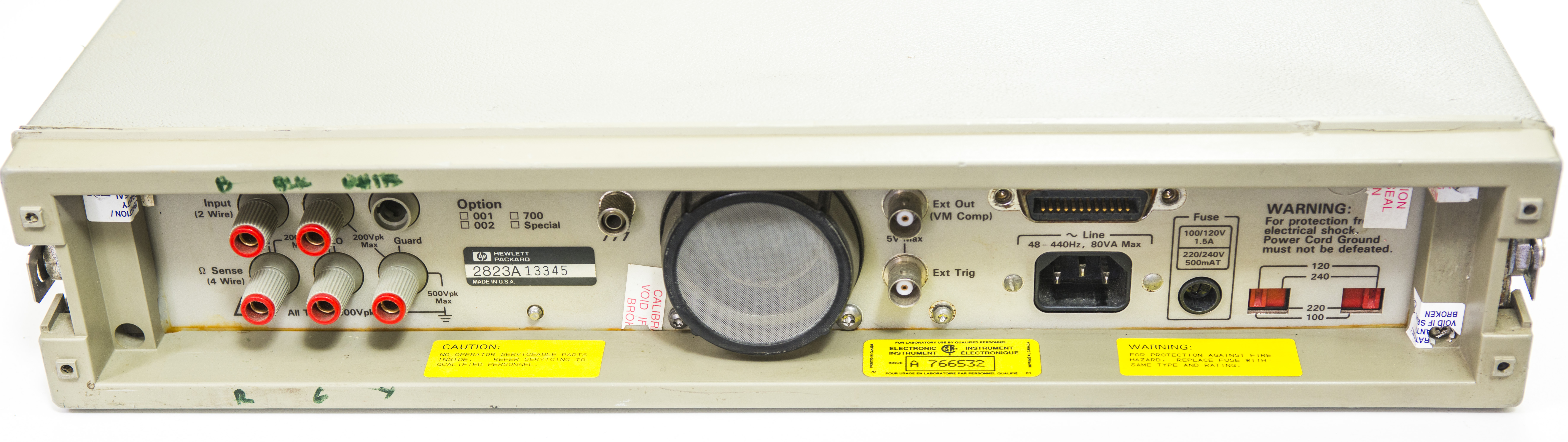
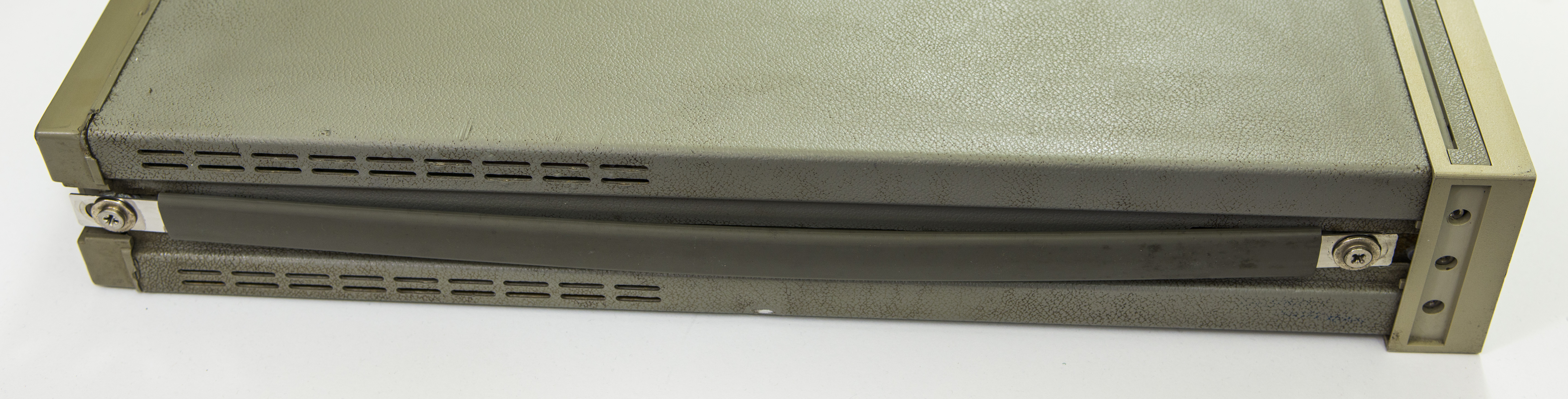
Image 5,6: HP 3458A side handle and rear panel
All sensitive analog boards are enclosed in separate insulated aluminum cage, held by plastic standoffs. This is called “Inguard” by HP terminology, because this cage is kept under guard voltage potential to isolate sensitive analog circuits from external signals, EMI and RFI.

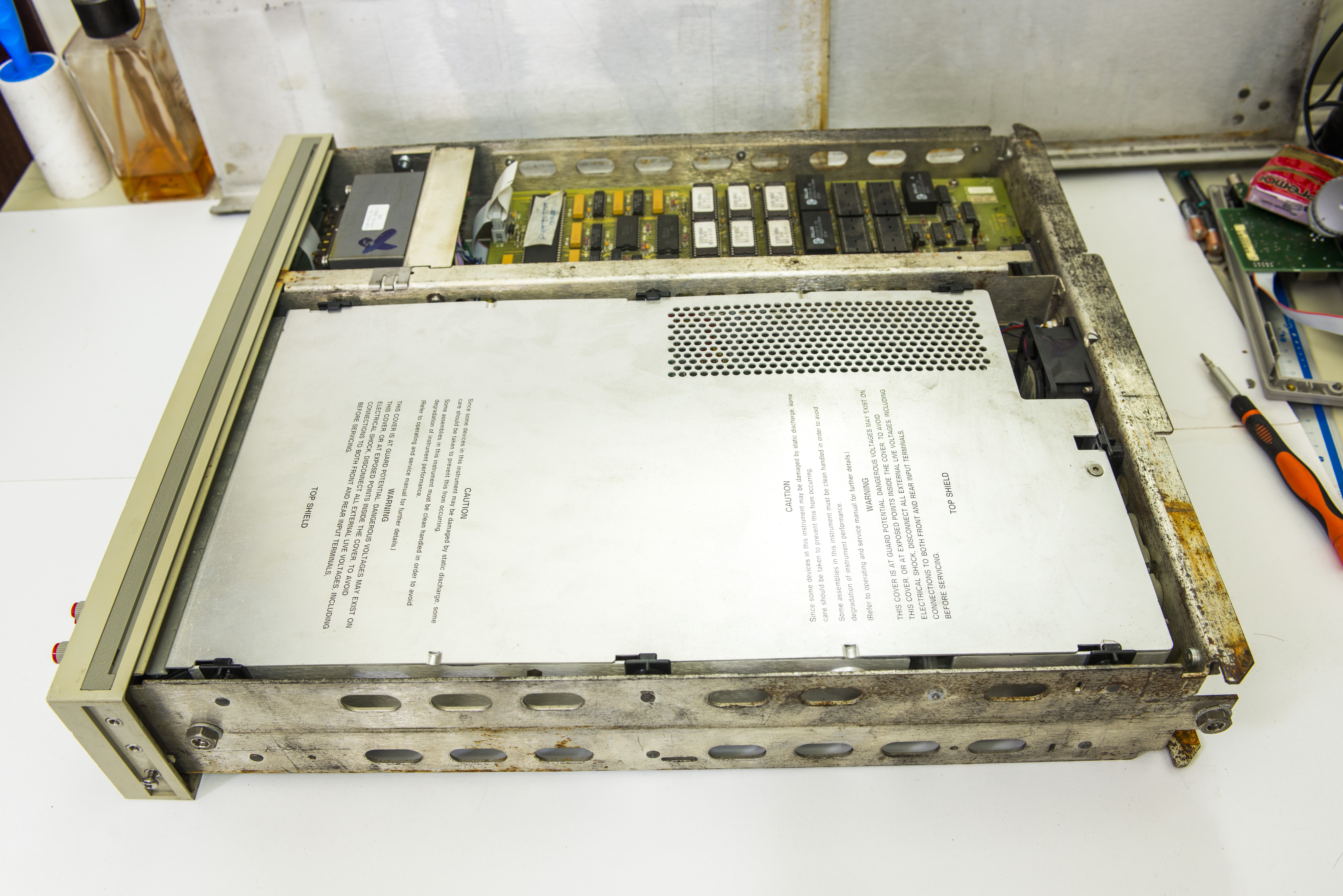
Image 7,8: HP 3458A internals with inguard shields
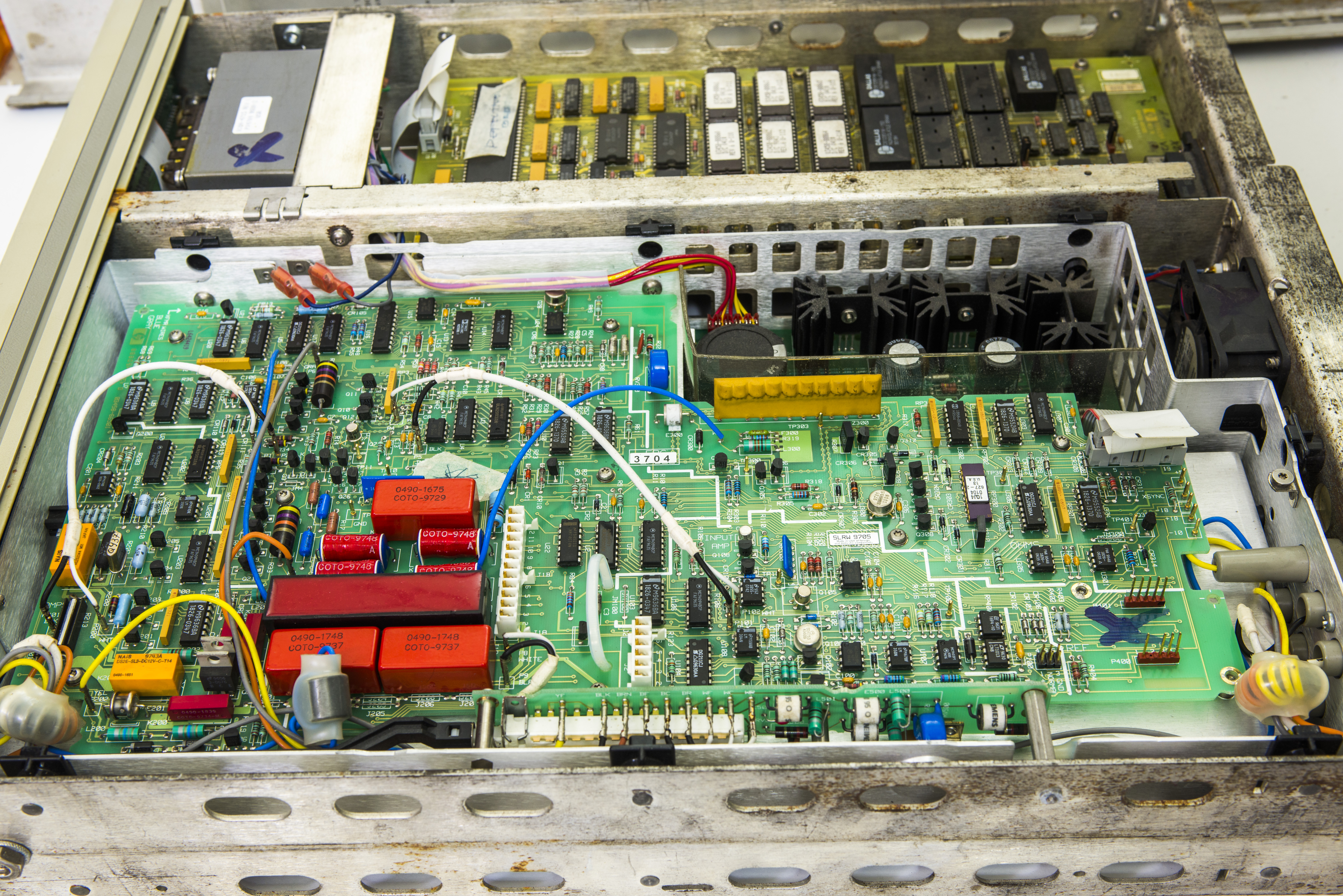
Image 9: A1 DC board overview
Pay attention to mains voltage selection switches, located near mains IEC connector. Using incorrect voltage setting (e.g. 120VAC with 220VAC mains) will likely to destroy transformer, as it is linear type and directly wired to mains! This is likely what happened to my unit by previous owner, and was a root cause of damage. New transformer cost is $337 USD + tax, so was rather pricey mistake.
Manuals references
A User’s Guide to Keysight 3458A Front Panel Operation
3458A Multimeter User’s Guide, Edition 7
Keysight 3458A Multimeter datasheet
Agilent 3458A : Quick Reference Guide, Edition 2, Dec 2000
3458A Multimeter Calibration Manual, Edition 7
3458A Multimeter Calibration Manual, Edition 6
Service notes
There is also number of service notes/engineering changes were published during years of 3458A’s lifecycle. If your unit is old, worth to check if any of them required to do.
Service note 3458-01C : A/D Linearity Improvement
Service note 3458-04A : Apparent failure at turn-on or when given a “RESET” command
Service note 3458-07B : Modification to Fix Intermittent Error “Multislope Rundown Conversion”
Service note 3458-08A : Incorrectly Labeled Line Voltage Switches May Cause Switch Setting Confusion
Service note 3458-10A : 3458A Documentation Available As “On-Line” Files
Service note 3458-12B : Outguard Firmware Upgrade: Enhancements, Fixes, & Changes
Service note 3458-12C : Outguard Firmware Upgrade: Enhancements, Fixes, & Changes
Service note 3458-13A : GPIB Communication Failures Using the 3458A
Service note 3458-14B : Calibration Error After Power “On” or After an “ACAL”
Service note 3458-17 : Errors May Occur if ACAL AC is Initiated From the 4-Wire Ohms Function
Service note 3458-20 : Bad SRAM causing Cal Ram batteries to fail prematurely
Repair workflow
As usual, we have project tracker, dedicated for 3458A repair so any one can contribute, or track the progress.
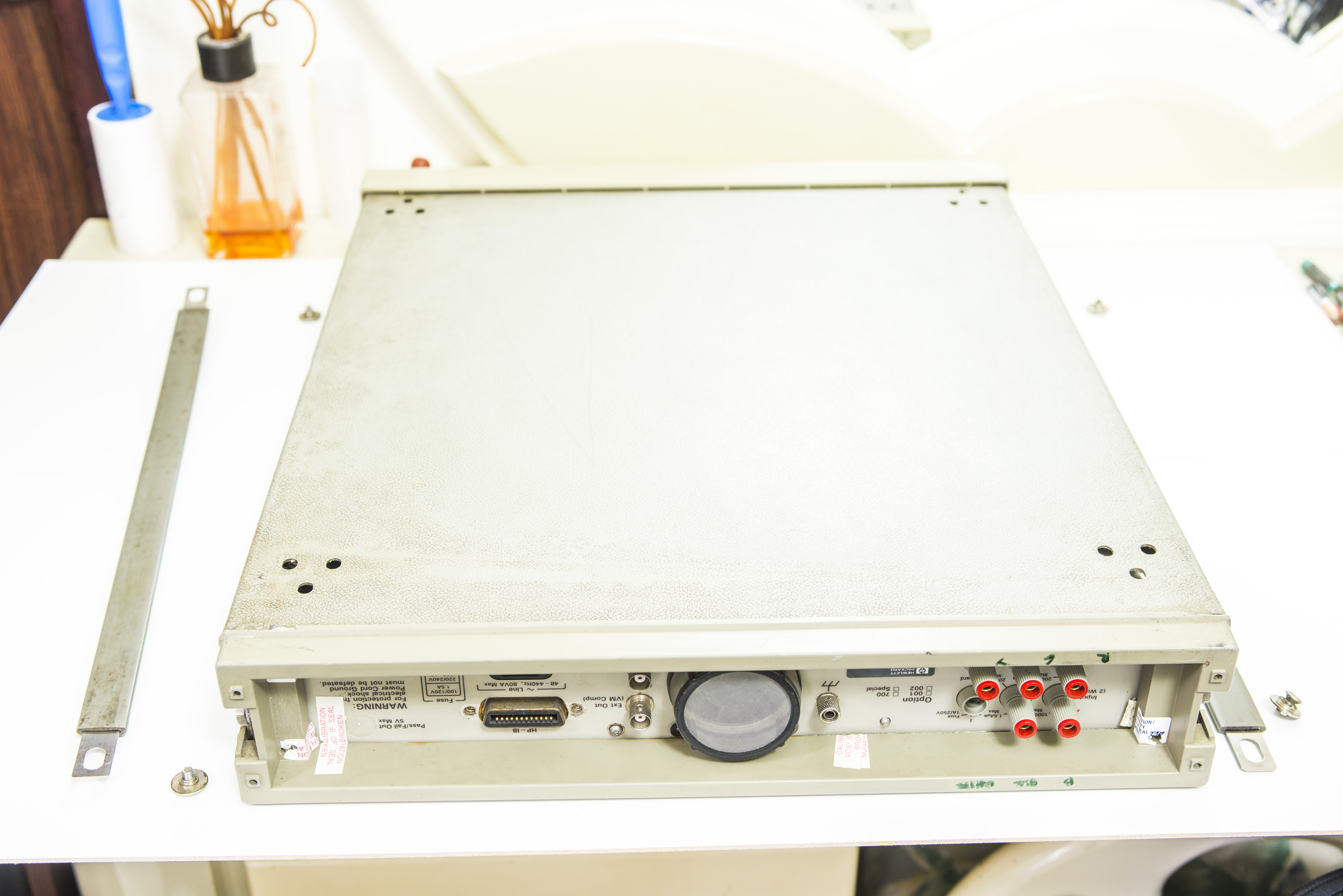

Image 10,11: Disassembly begins
Before starting any repair, good idea to read thru repair manuals, to get idea of board functions and purpose. HP has both assembly and component level repair manuals, which include full schematics and board assembly drawings. AFAIK it’s the only 8½ DMM which have complete schematics. I still remember repair efforts and countless hours without schematics, deciphering circuitry in Keithley 2001 DMM.
3458A Multimeter Assembly Level Repair Manual, Edition 2
3458A Multimeter Component Level Repair Manual
Also worth to note requirement of adjustments/recalibration procedures, from repair manual, in case of board replacement/repair:
| Ref Designator | Agilent Part Number | Assembly Description | Adjustments Needed |
|---|---|---|---|
| A1 | 03458-66501 | Front panel | DC circuitry Offset, DC Gain,Resistance, and DC Current Adjustments |
| A2 | 03458-66502 | AC converter | AC Adjustment |
| A3 | 03458-66503 | A/D converter and Inguard logic | Offset, DC Gain,Resistance, DC Current,and AC Adjustments |
| A4 | 03458-66504 | Inguard power supply | ACAL ALL |
| A5 | 03458-66505 | Outguard Controller | Offset, DC Gain,Resistance, DC Current and AC Adjustments |
| A5 (001) | 03458-66515 | Outguard Controller (Opt 001) | Offset, DC Gain,Resistance, DC Current, and AC Adjustments |
| A6 | 03458-66506 | Outguard power supply | ACAL ALL |
| A7 | 03458-66507 | Display logic | ACAL ALL |
| A9 | 03458-66509 | DC reference | Offset, DC Gain,Resistance, and DC Current Adjustments |
| A9 (002) | 03458-66519 | DC reference (Opt 002) | Offset, DC Gain,Resistance, and DC Current Adjustments |
| A9 (HFL) | 03458-66529 | DC reference (Opt HFL) | Offset, DC Gain,Resistance, and DC Current Adjustments |
| A10 | 03458-66510 | Front/rear switch | Offset Adjustments,ACAL ALL |
Table 3: 3458A Board model numbers and definitions
Some parts are available for order from Keysight. List of parts and cost from Keysight, Excel table
As expected, most mechanical parts are affordable to allow minor repair, but when we start looking at PCBA level repair cost is quickly jumps to thousands of dollars, making whole project worthless.
HP/Agilent/Keysight does not support users doing component-level repairs, so don’t expect answers to questions like “I have problem A with my meter, found broken component R532 and U245, can you sell me new component?”
Overall parts view:
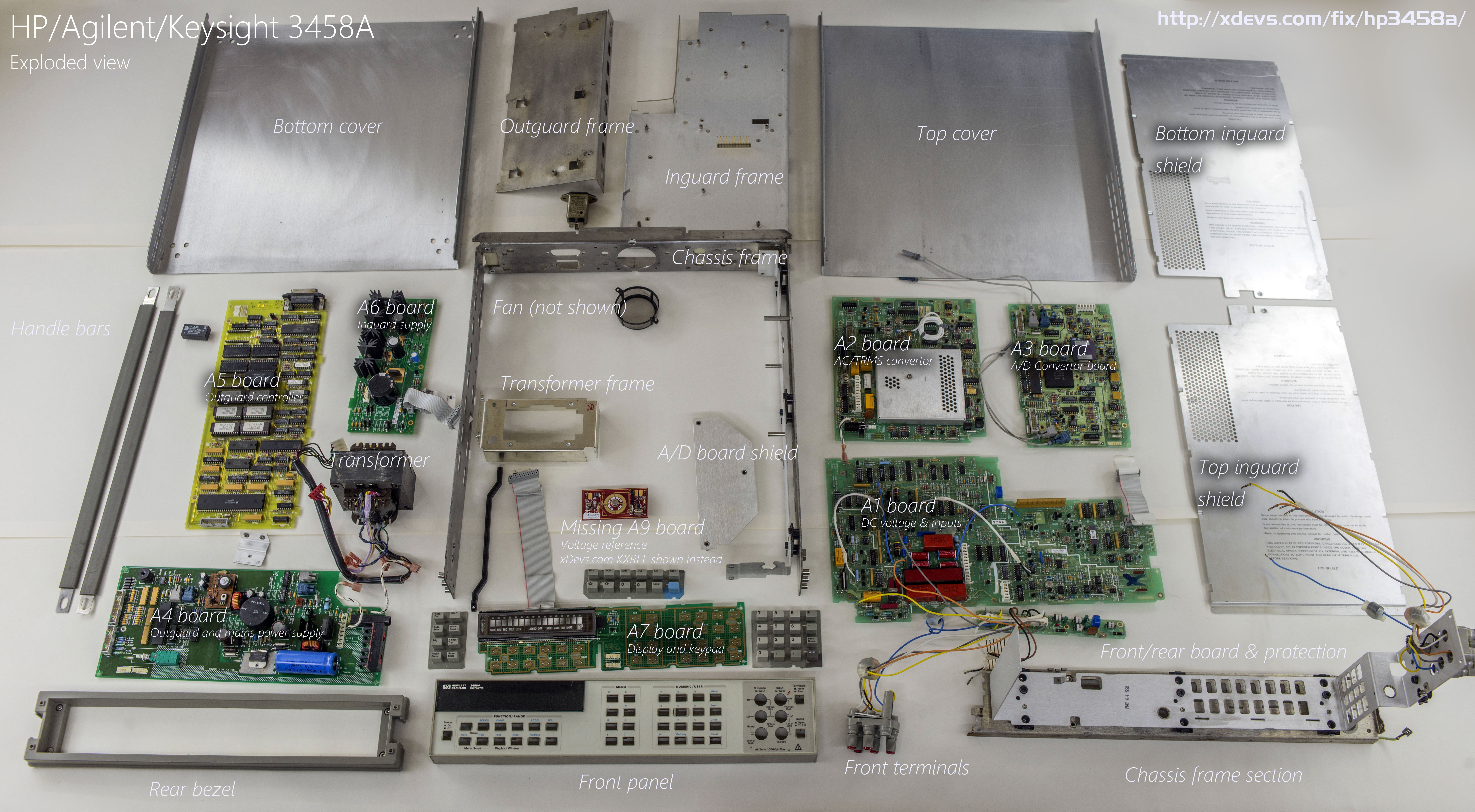
Image 12: Exploded view of HP 3458A DMM
Except missing A9 DCV reference board, everything is there, no missing parts on boards. Vacuum-fluorescent display glass is not damaged (barium flash on glass from getter is shiny dark, if air leak into tube it would become white)
Boards condition check
Before doing any repairs or applying power, wise to check physical condition of components and boards inside instrument. Often this easy operation can spot obvious failures, such as blown MOSFETs, burnt resistors or missing parts, saving time for further repair.
Have a close look on electrolytic capacitors, especially if instrument’s age is more than 10 years. If you see leaked electrolyte or bulging capacitors, do not apply power. Replace broken parts and clean board thoroughly, to avoid further damage. Often electrolyte soaks into PCB via’s and eat copper tracks, so pay close attention to condition. If any visible discoloration found, use DMM to check connection resistances, and rewire broken nets, if needed.
I usually replace old electrolytic aluminum capacitors to fresh ones even if they look okay. It does not cost much, but will save the question regarding if original ones are good or bad, or at borderline. Important to keep same voltage and capacitance rating, and ESR/ESL spec as original caps, unless you really know what you are doing.


Images 13-18: Condition of PCBAs
Now take a look on PCB and fix issues as we go. Order listed as diagnostics were done.
A7 Front panel
Front panel must be removed in order to remove mains transformer. To do so, lift right side of panel and release it from chassis frame. Be careful with front panel assembly, as vacuum display glass is fragile.
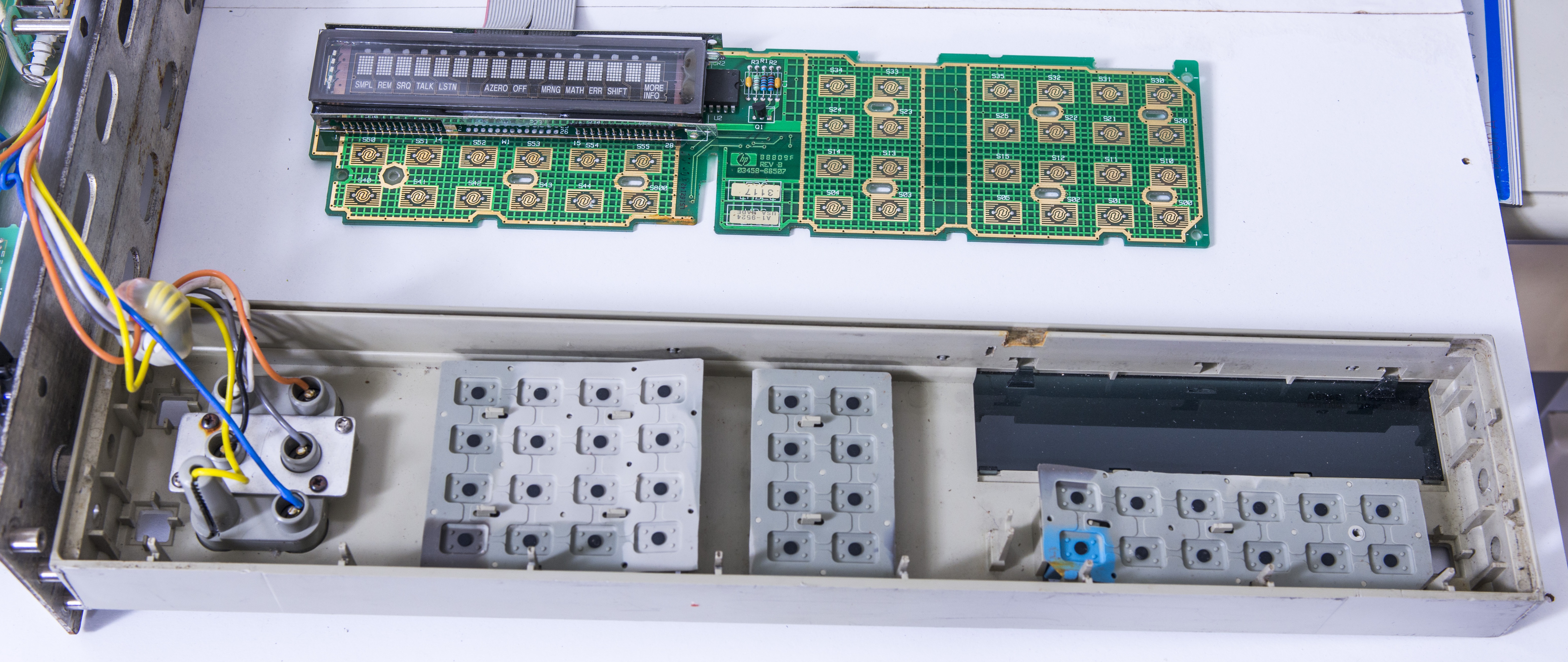
Image 19: Front panel board and keypad
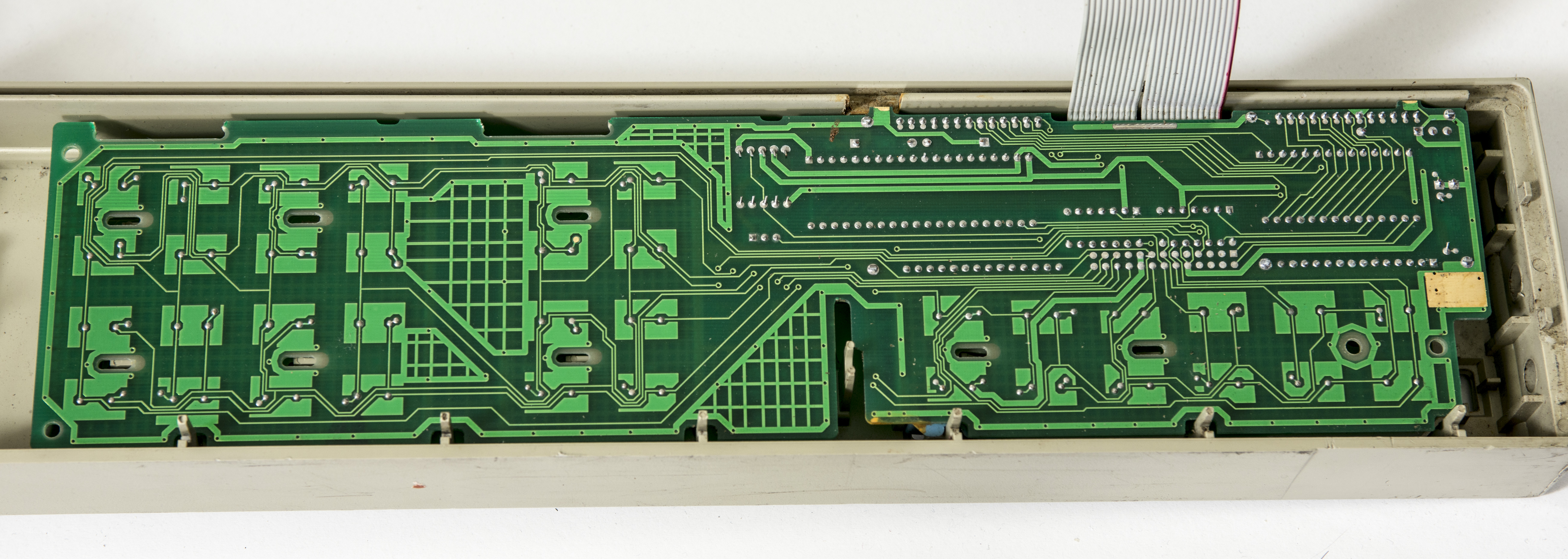
Image 20: 03458-66507 Board in place
Looking good, just minor cleaning required..
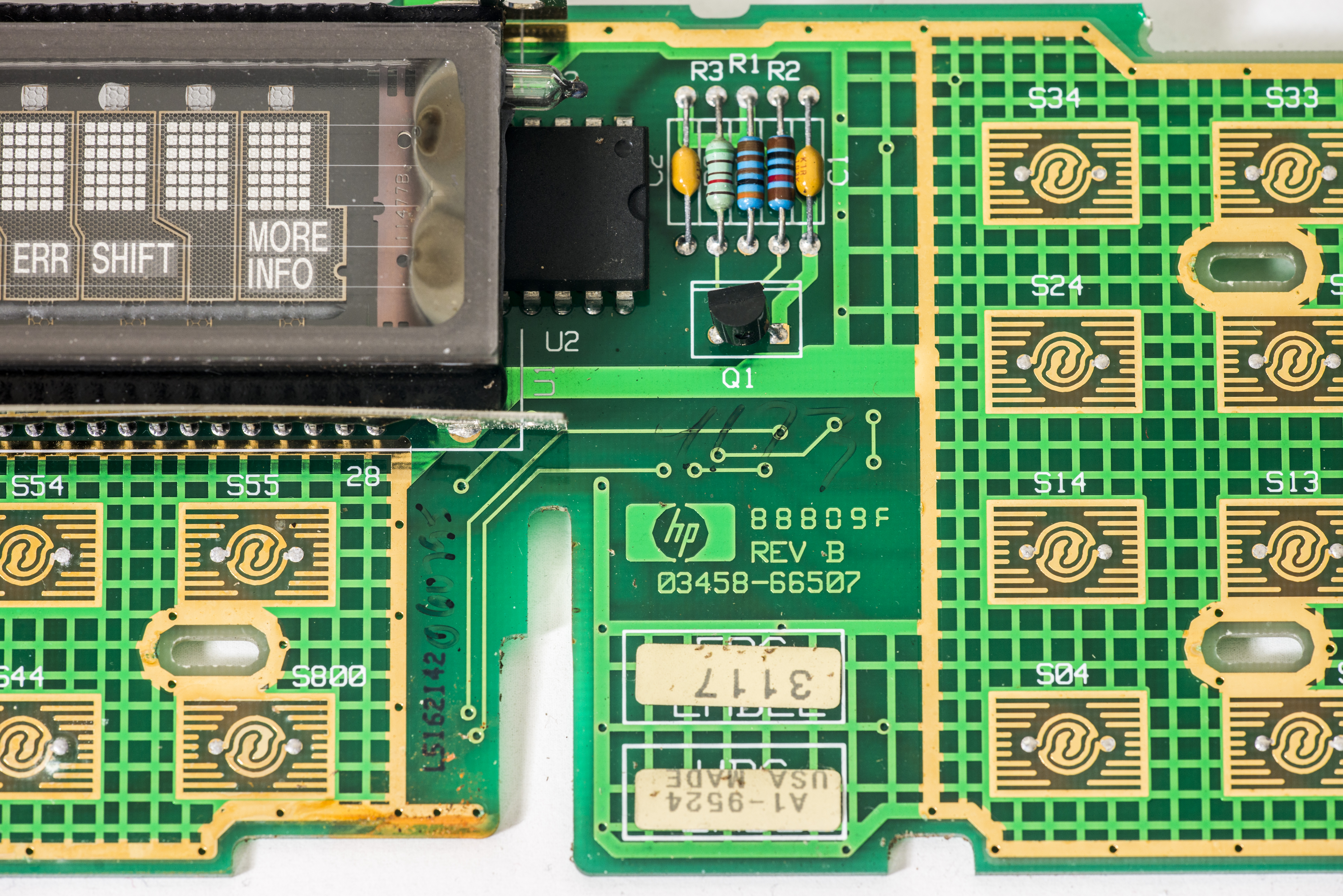
Image 21: Front panel PCB label
Image 22: Front terminals housing
Front panel PCBA label and front binding post terminals.
A6 Outguard power supply assembly
Let’s deal with Outguard stuff first, as we cannot test or check anything on analog Inguard side, unless main processor, front panel and interface is fully operational.
It’s wise to start from testing power supplies.

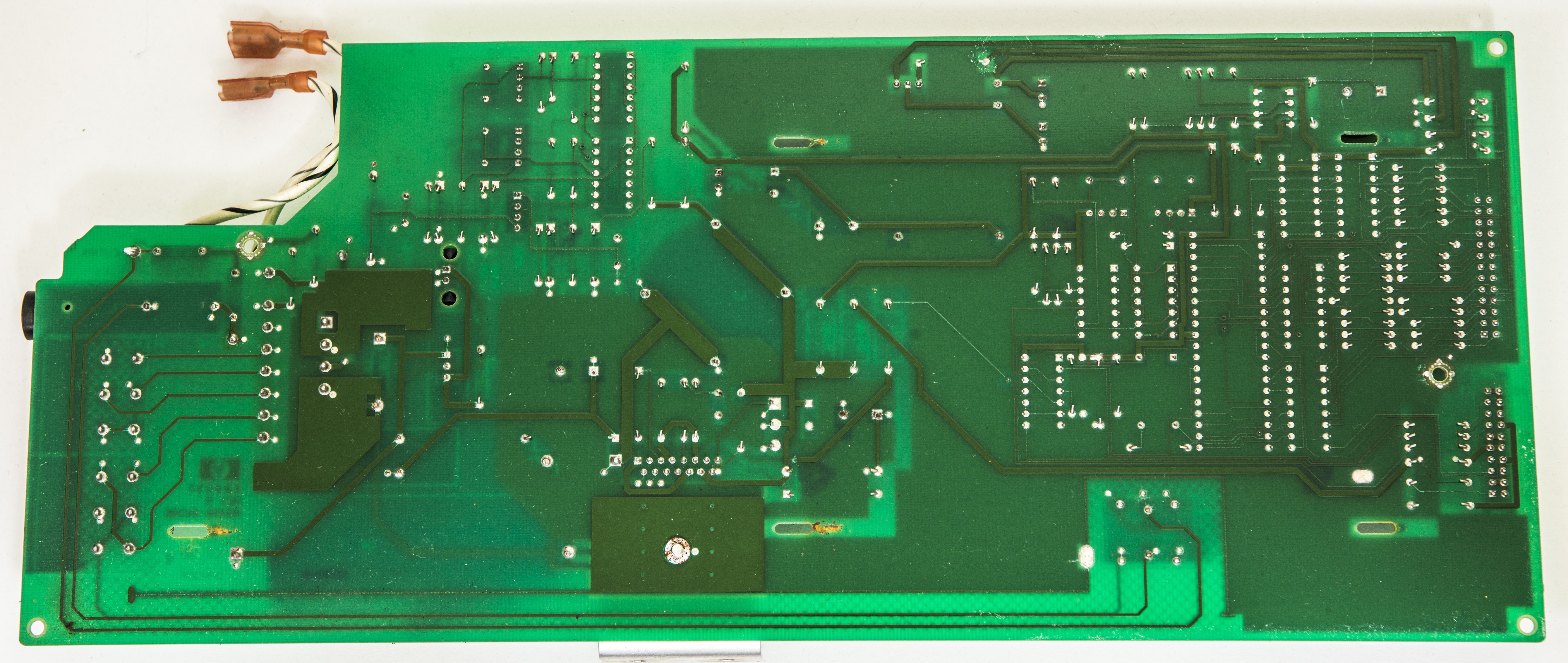
Image 23,24: A6 03458-66506 power supply PCBA, top and bottom side
After installing fuse, meter digital section can now power on, giving short beep and displaying error message on VFD.
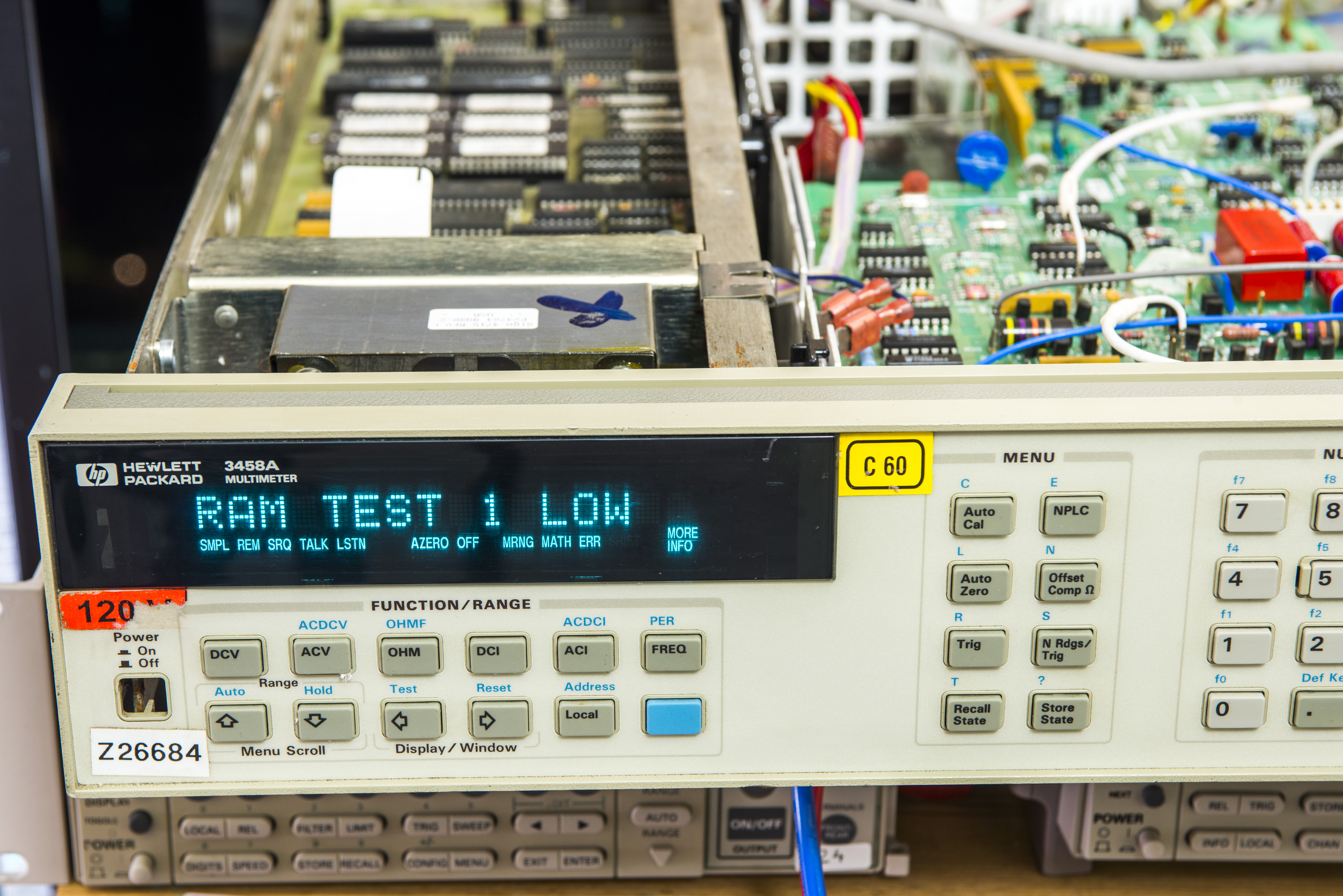
Image 25: RAM TEST 1 LOW ERROR, first power on
Display looks bright and nice, it’s great news, as old VFD segments often fade badly if being operated for long periods of time.
Error message RAM TEST 1 LOW meaning there is fault with digital board. So let’s troubleshoot digital section first, which is board A5. We will get into it later, let’s finish up with A6 supply first.
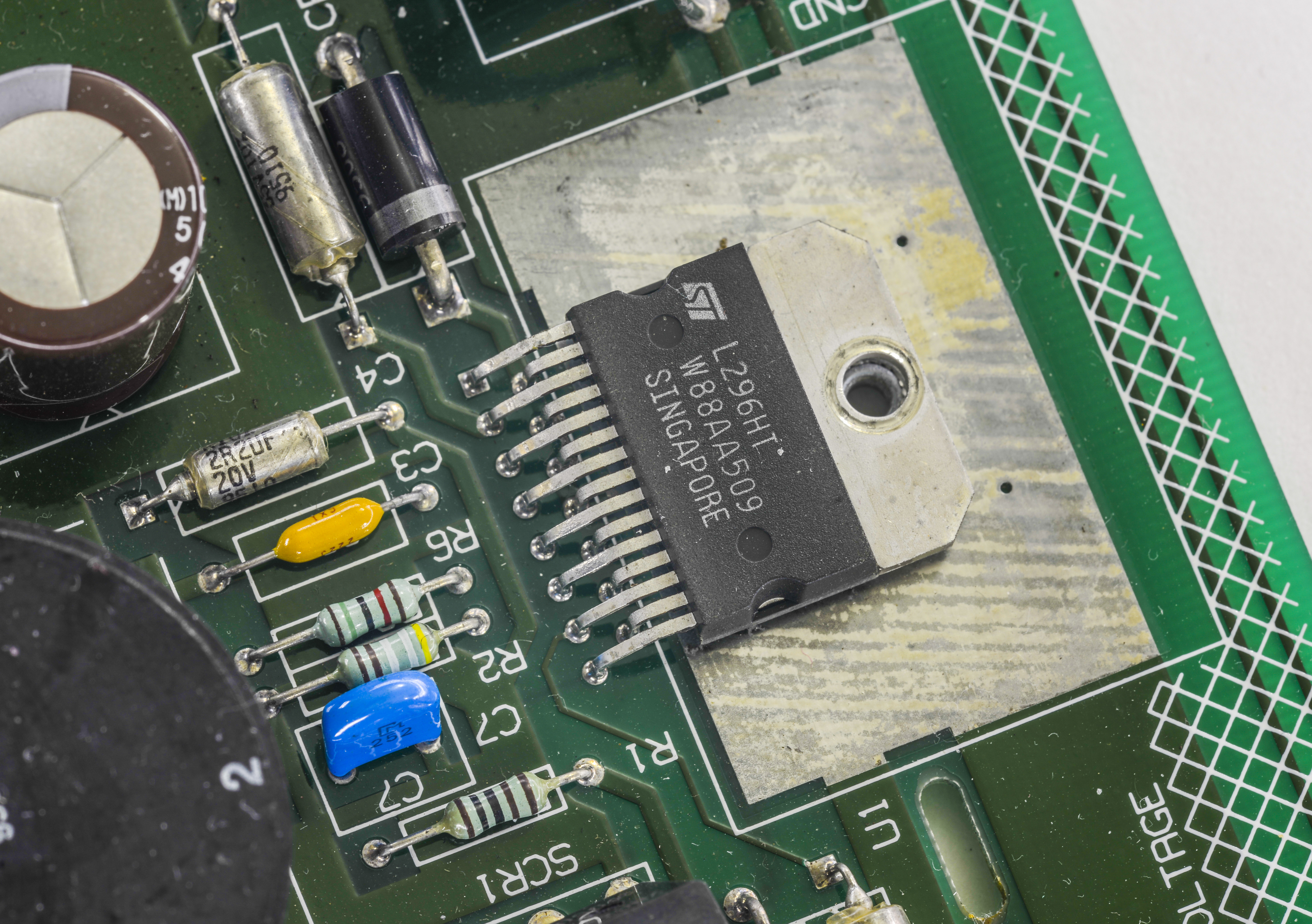
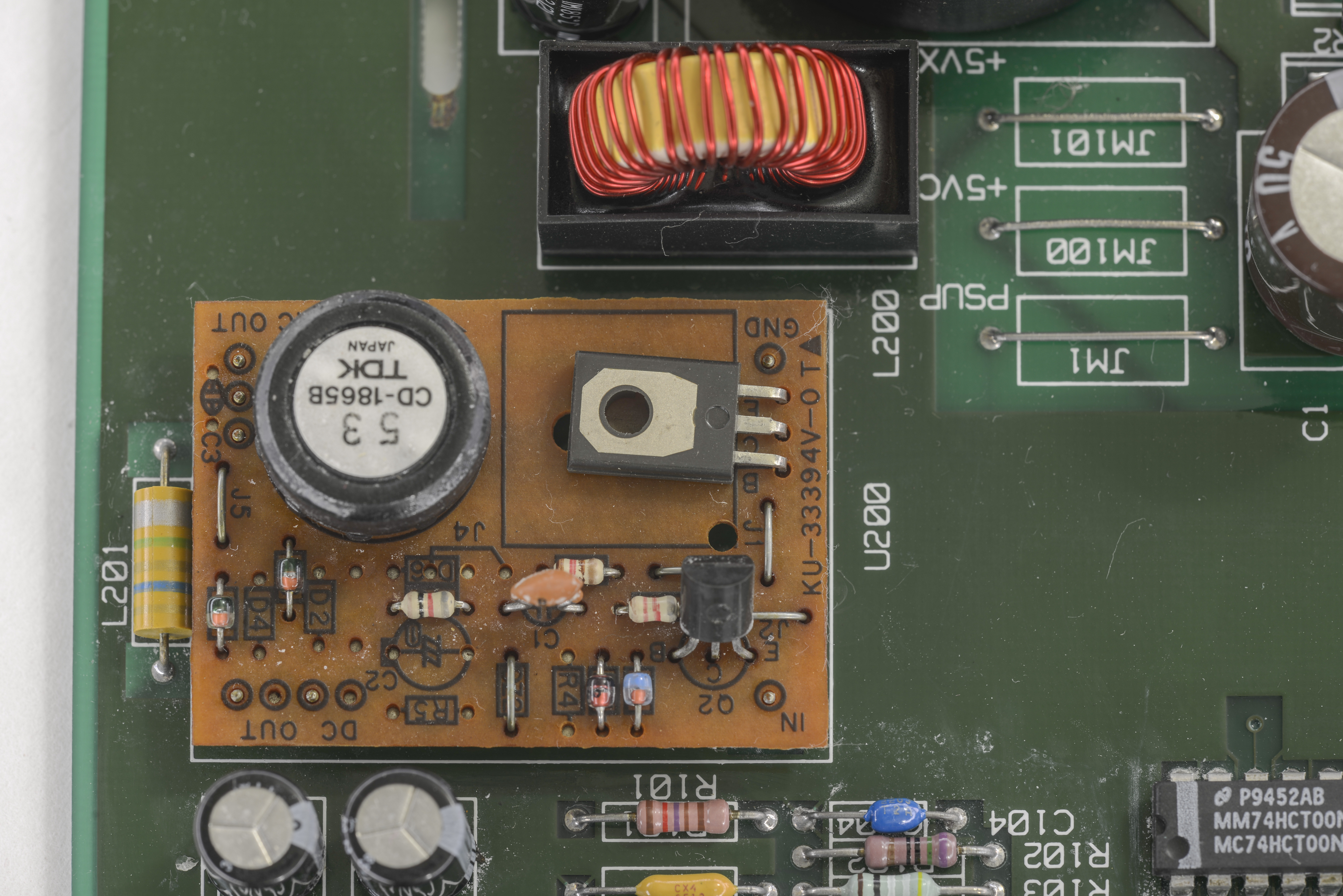
Image 26,27: Digital +5VDC supply reg and VFD DC/AC/DC converter
This board is host for two main supplies, high-current +5V supply for digital controller board, front panel board, display and fan. Main power convertor is based around switching ST L296, which is capable of supplying up to 4 amps of current.
Small board with U200 refdes features simple DC-DC/AC to provide alternating voltage to front panel vacuum-fluorescent display filament and +60VDC to its segments.

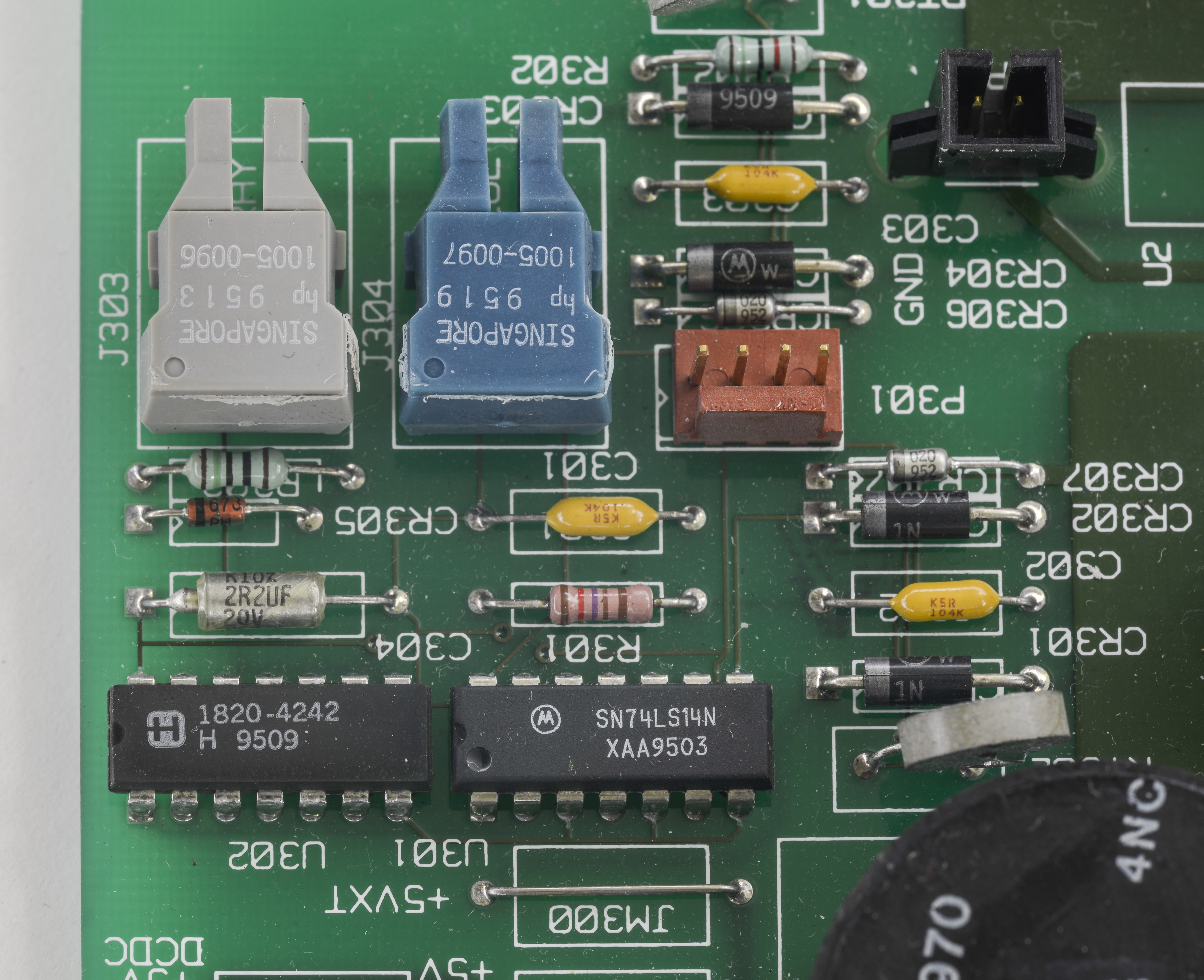
Image 28,29: Front panel 8051 MCU and isolation VersaLink optics to inguard section
Big chip in DIP package is Intel’s 8051 microcontroller, preprogrammed with 03458-85502 mask firmware. This controller handles buttons, buzzer and display operations. NE555 nearby provides tone signal to buzzer.
Let’s take a look on system fan. First, it’s supply:
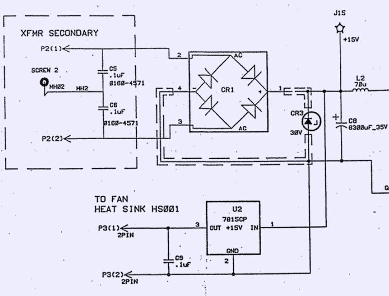
Image 30: FAN regulator schematics
It’s little confusing, if taking into consideration +15V marking and 7815 LDO after diode bridge. Had measured actual voltage going to fan, it is indeed +15.1 VDC.
Fan 7815 linear regulator have little clip heatsink, and bearing HP custom code marking.

Image 31: Fan regulator BOM, indeed +15V supply
According to CLIP’s BOM list its regular MC7815CT linear regulator in TO220 package, designed to provide 14.4/15.6 VDC output.
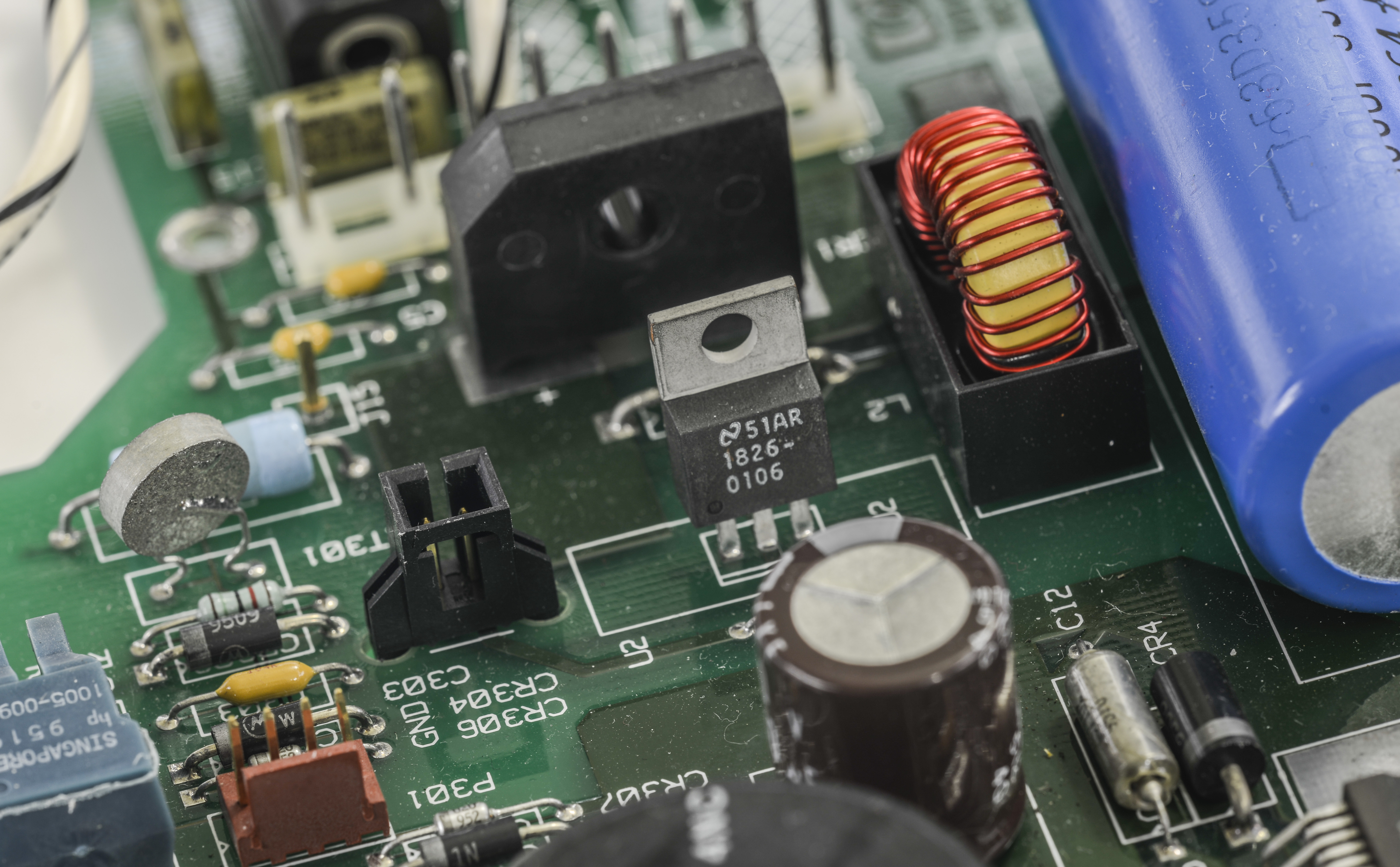
Image 32: Regulator on PCB, heatsink removed
Black 2-pin connector at left of regulator is fan header. Fan in my unit is completely stuck and blocked by gunk, so instead of wasting time on fan cleaning, I’ll just replace it with same specced new one from NMB.

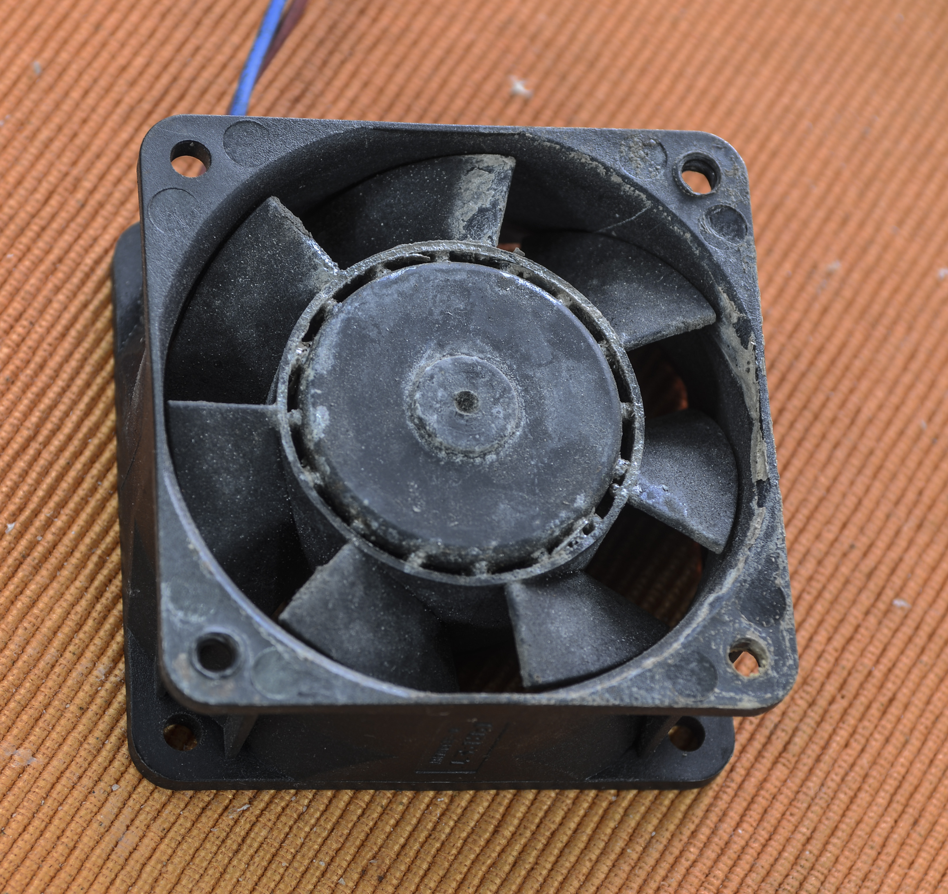
Image 33,34: Broken PAPST fan, front and rear view
Original fan is 60×60×25mm sized, DC type with just two wires. Made in Germany by respectable manufacturer, PAPST. Interesting to see, that fan is actually rated from 6 to 15VDC, while most of similar small DC fans are usually 5, or 12 or 24 VDC.
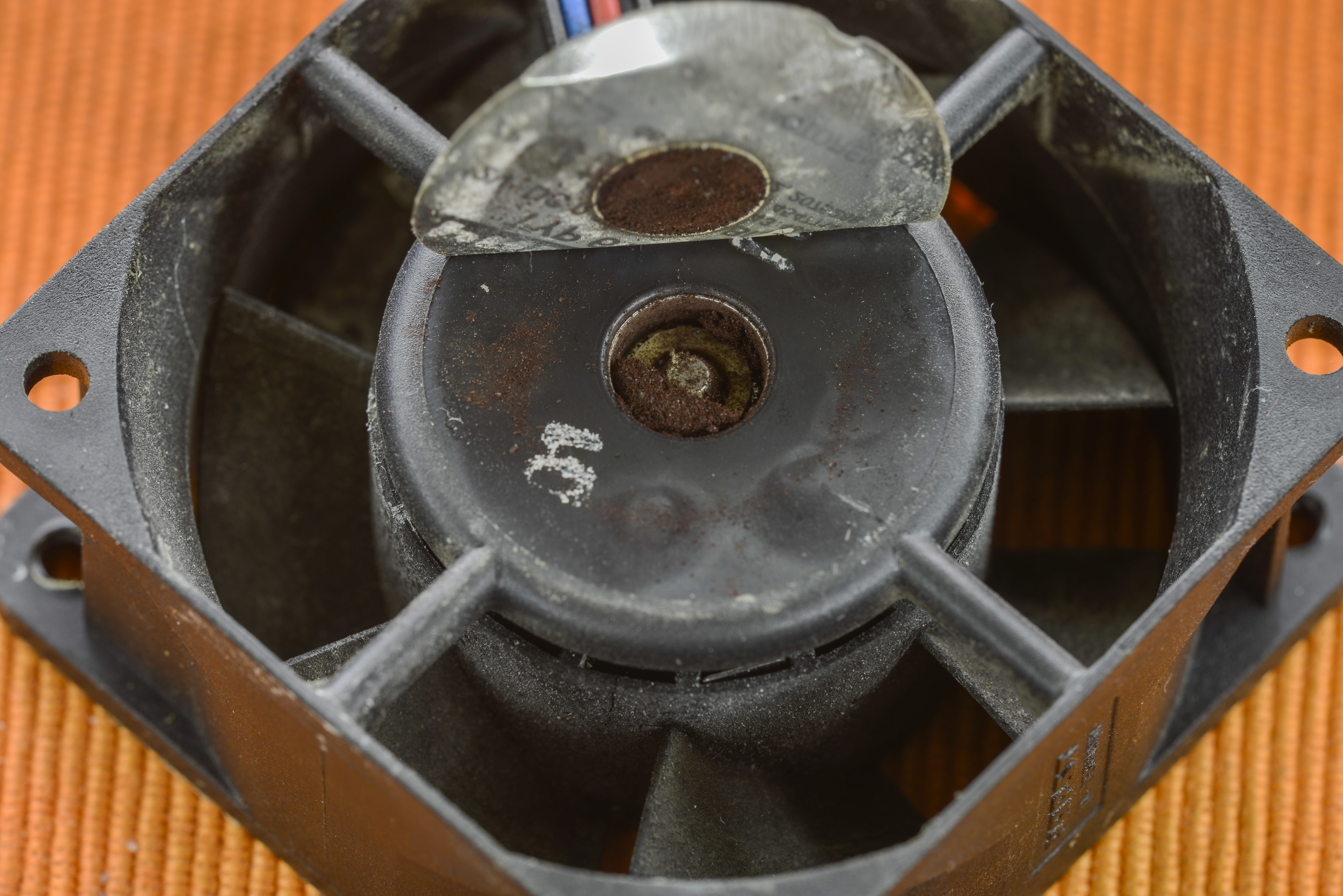
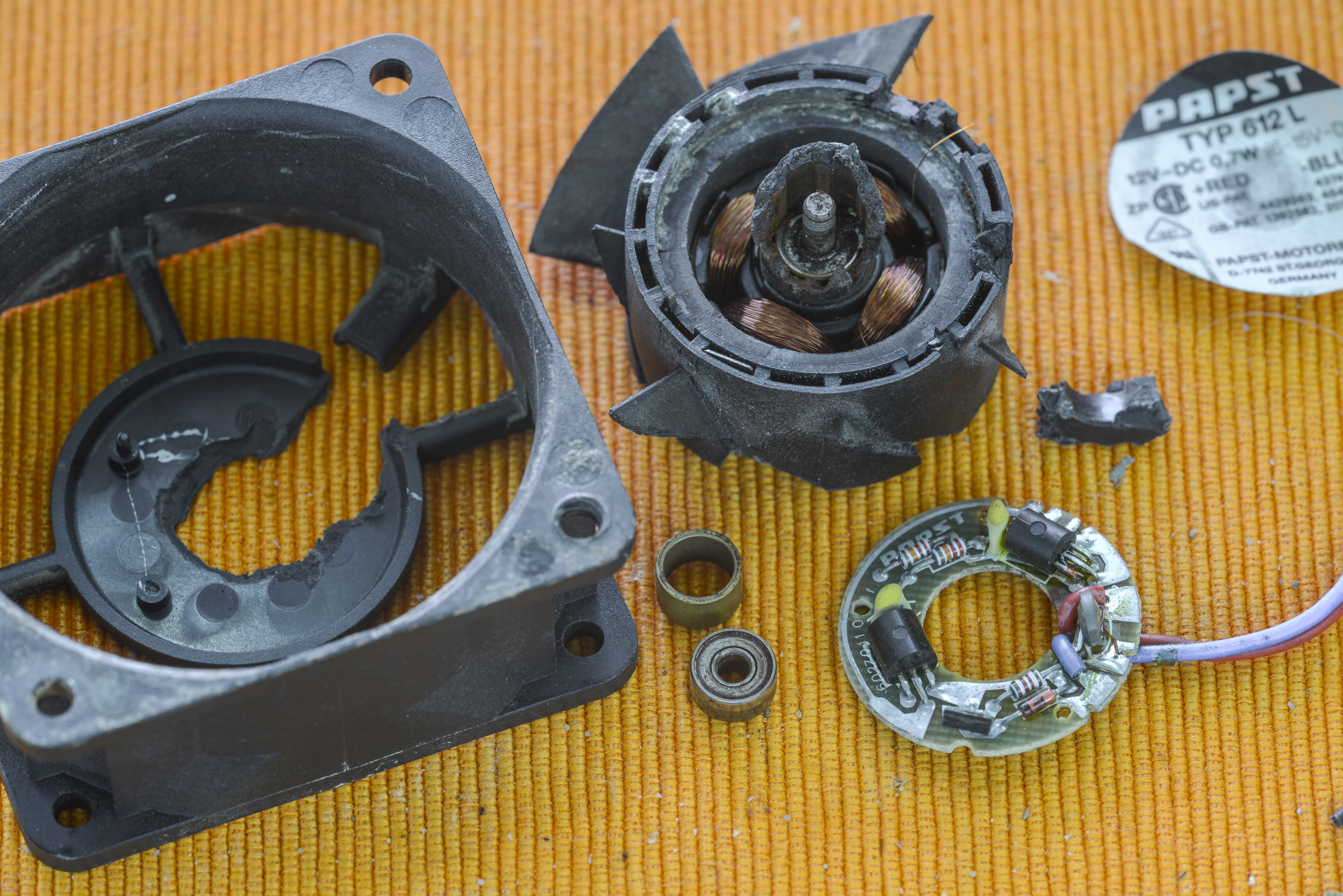
Image 35,36: Gunk in fan motor and motor board
My favorite destructive analysis reveals fan support with dual ball-bearings. Lubricant was long gone, resulting metal-type dirt and specs in motor.
I desoldered original fan wire, so I’ll use it with new fan, saving trouble with cable length and connector matching to A6 board.
I also ordered some capacitors from DigiKey to replace all electrolytes on this board. You can call me paranoid and insane, but I would not trust 20 year old electrolyte capacitors, even if they are made by 1st tier manufacturers.
Removing VFD supply board as well to clean:
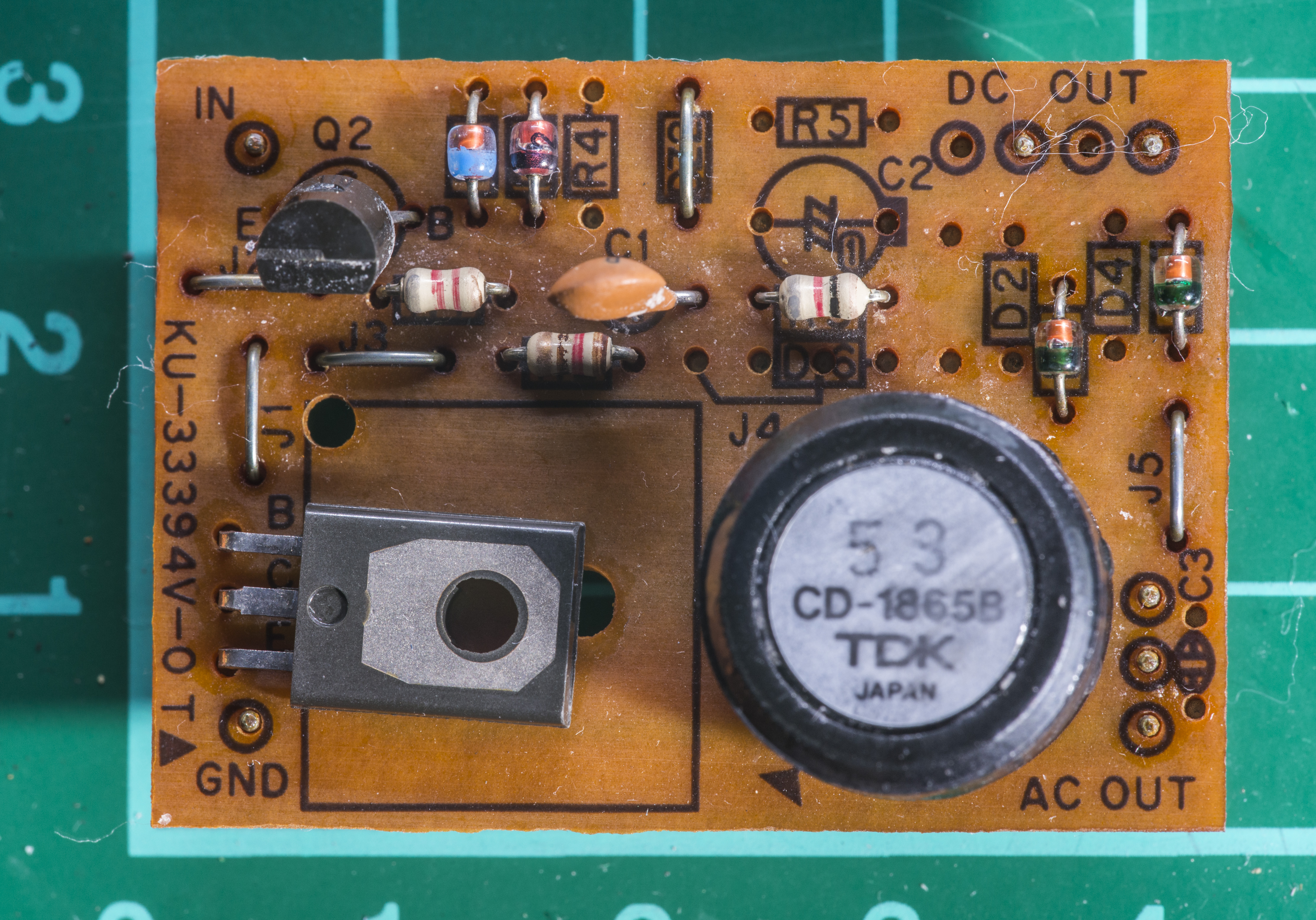
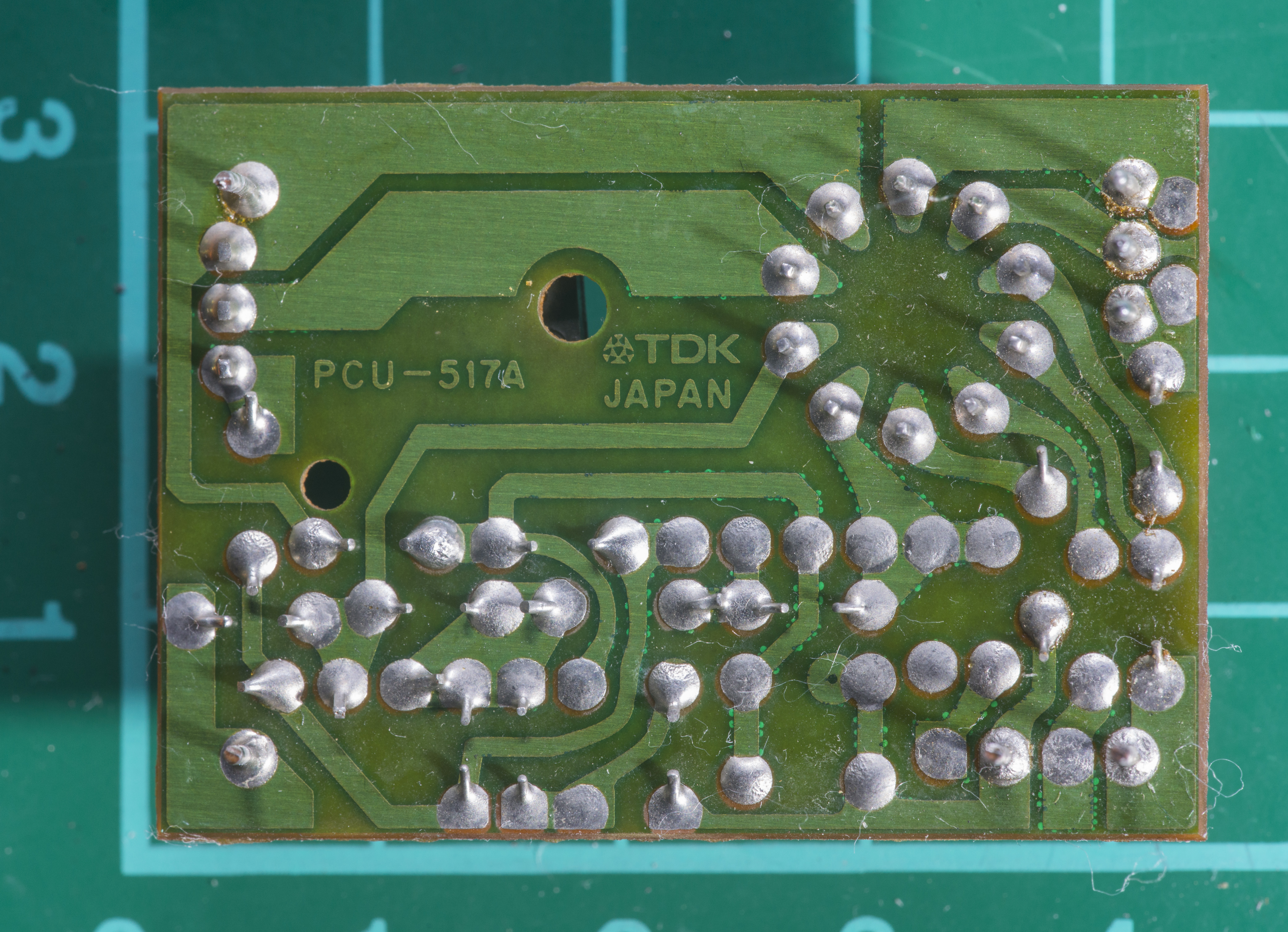
Image 37,38: High-voltage DC/AC/DC TDK power module for VFD supply
It’s a TDK-CD1865B DC-DC/DC-AC module. It takes +5VDC input and generate +50VDC and VAC voltage for filament.
Electrolytic capacitors looked alright, so most of people would think – Hey, those caps probably okay, don’t waste your time? . No, better be safe than sorry… Take them out, and say thank you later.
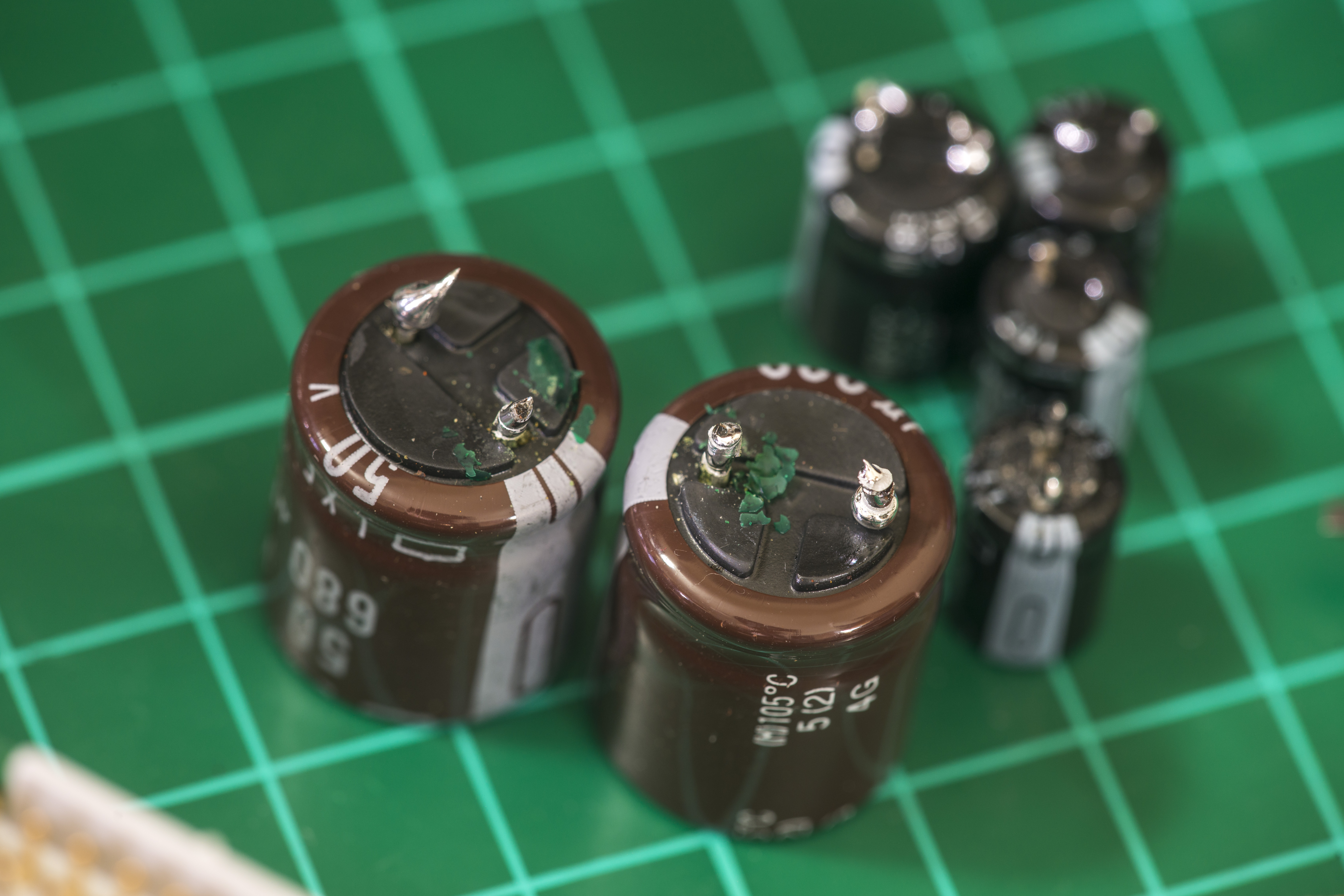
Image 39: Leaking capacitors from A6 board
Now it’s visible. Electrolyte got already out and started its destruction activities. Green pieces are actual PCB’s solder mask.
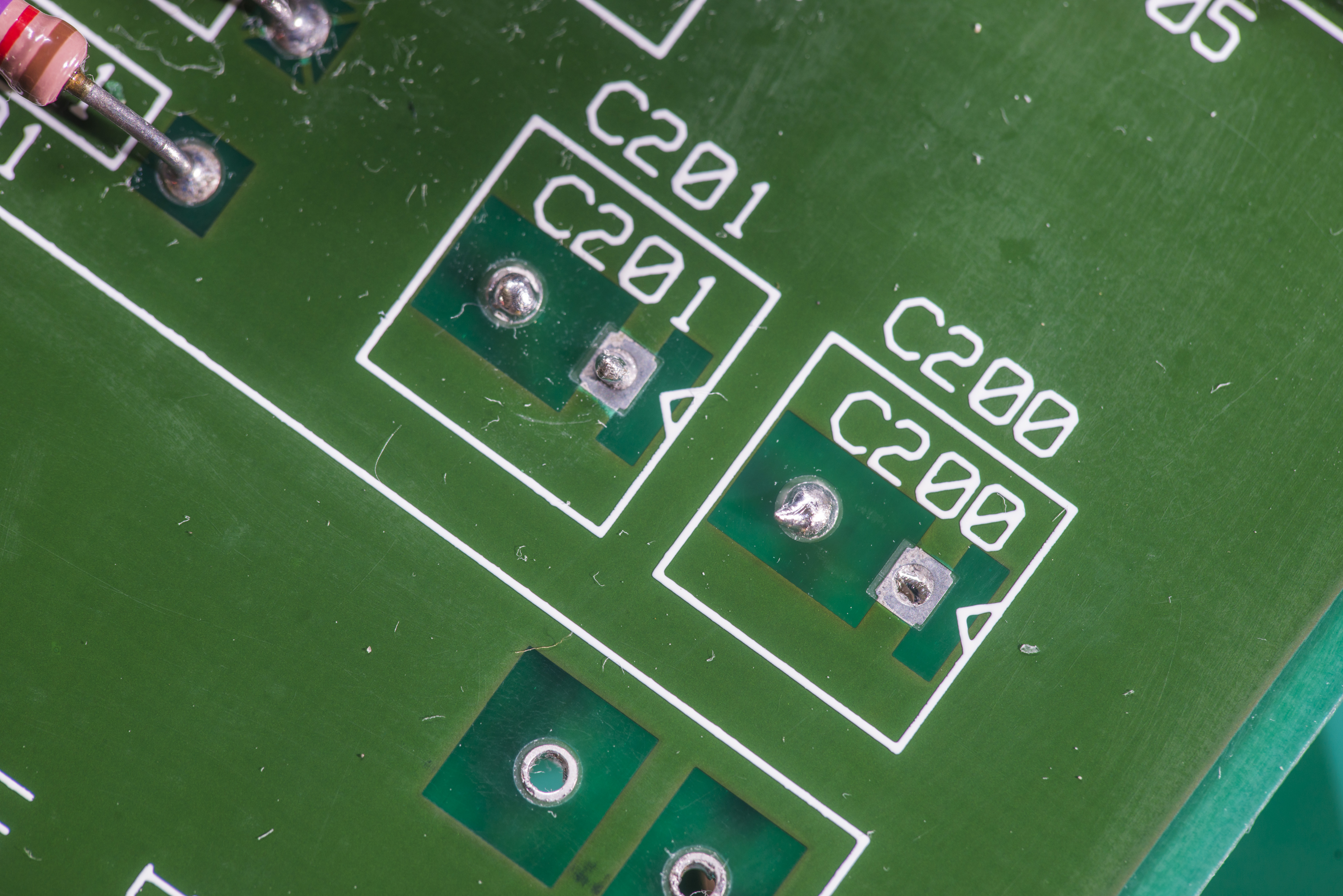
Image 40: Capacitors footprint
Small ones did not do any damage (yet), but bigger ones…


Image 41,42: Cleaning PCB required due electrolyte corrosion and solder mask damage
Now I am really glad that we did not cut corners here, and removed them. And it’s nice to have HP 3458A with only 2-layer PCBs, no risk of inner damages. I’ll just clean it to shiny copper, add layer polyurethane enamel film around pins , just to be future-proof. Caps I bought from DigiKey are long-life, rated for +105°C, and so should work a treat for many years after replacement.
I was wondering and measured old caps too, for series capacitance and resistance, with help of repaired HP 4263B
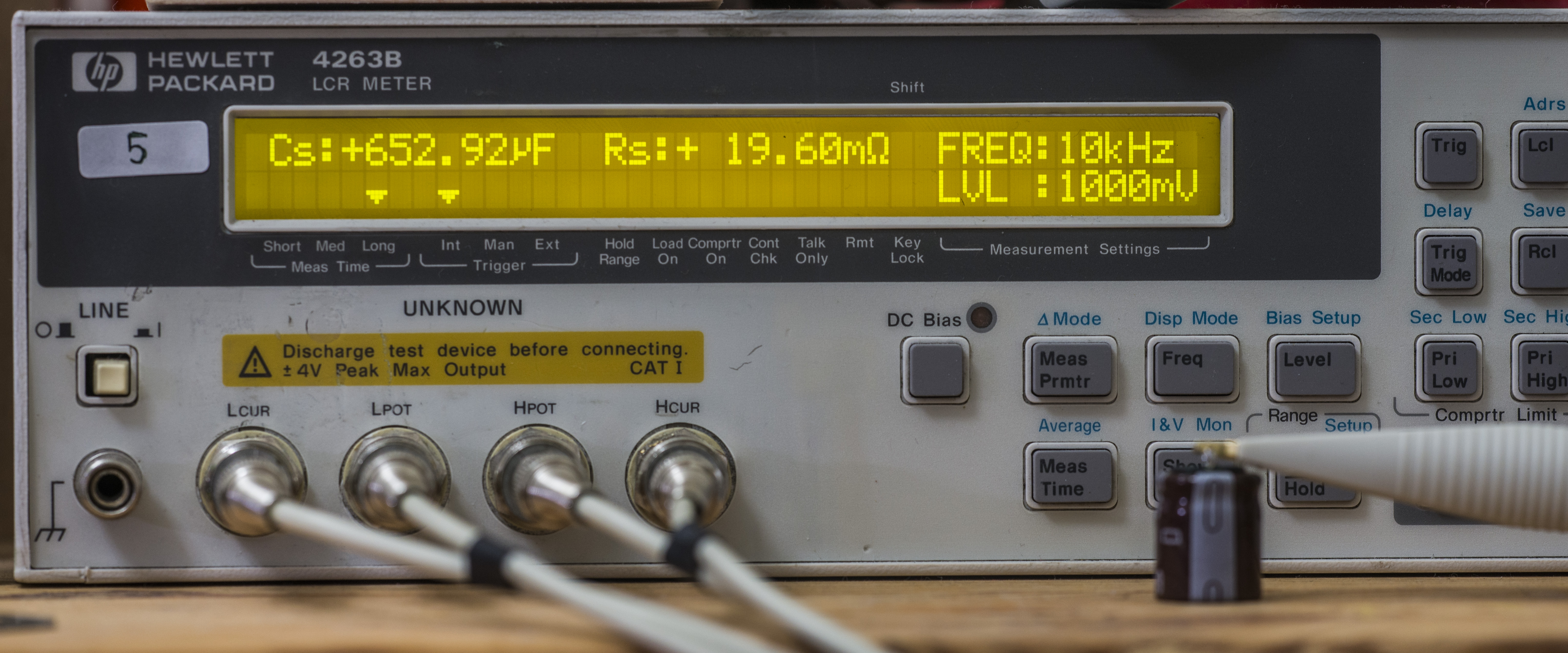

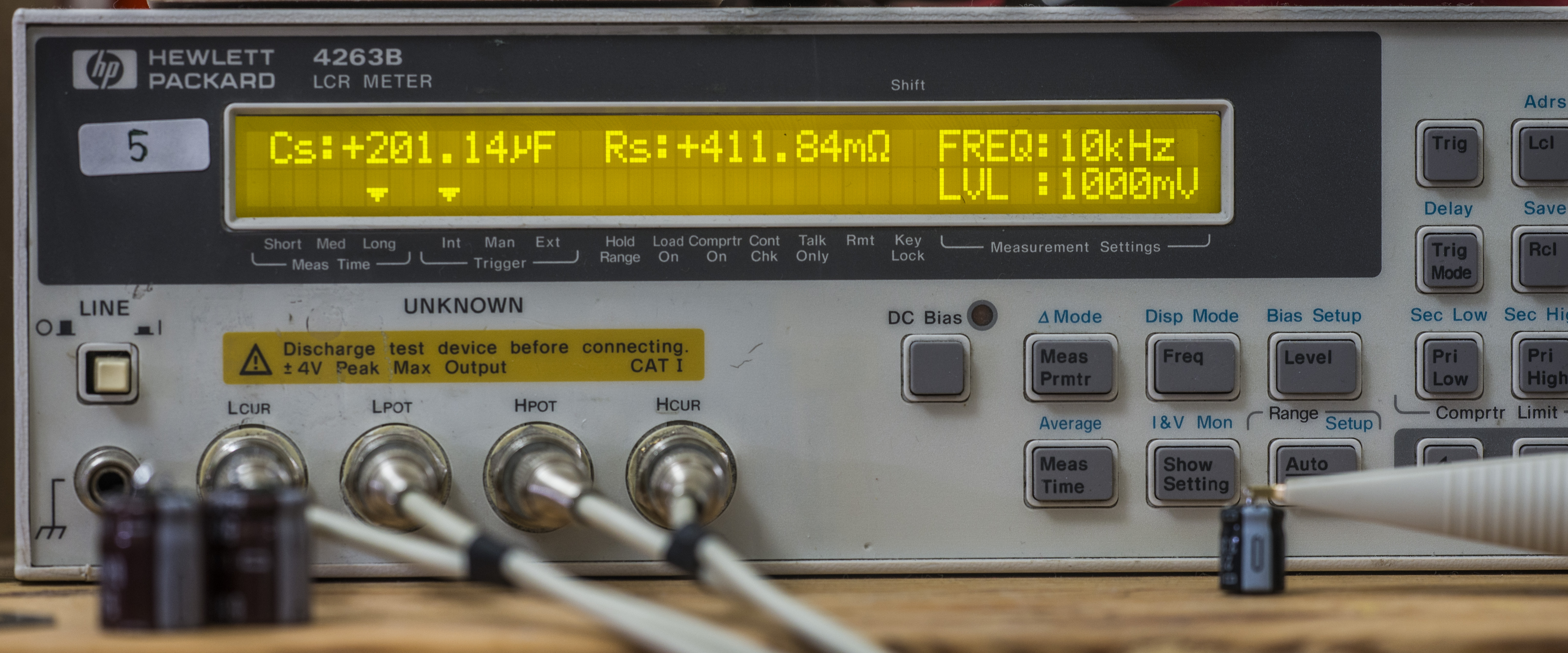
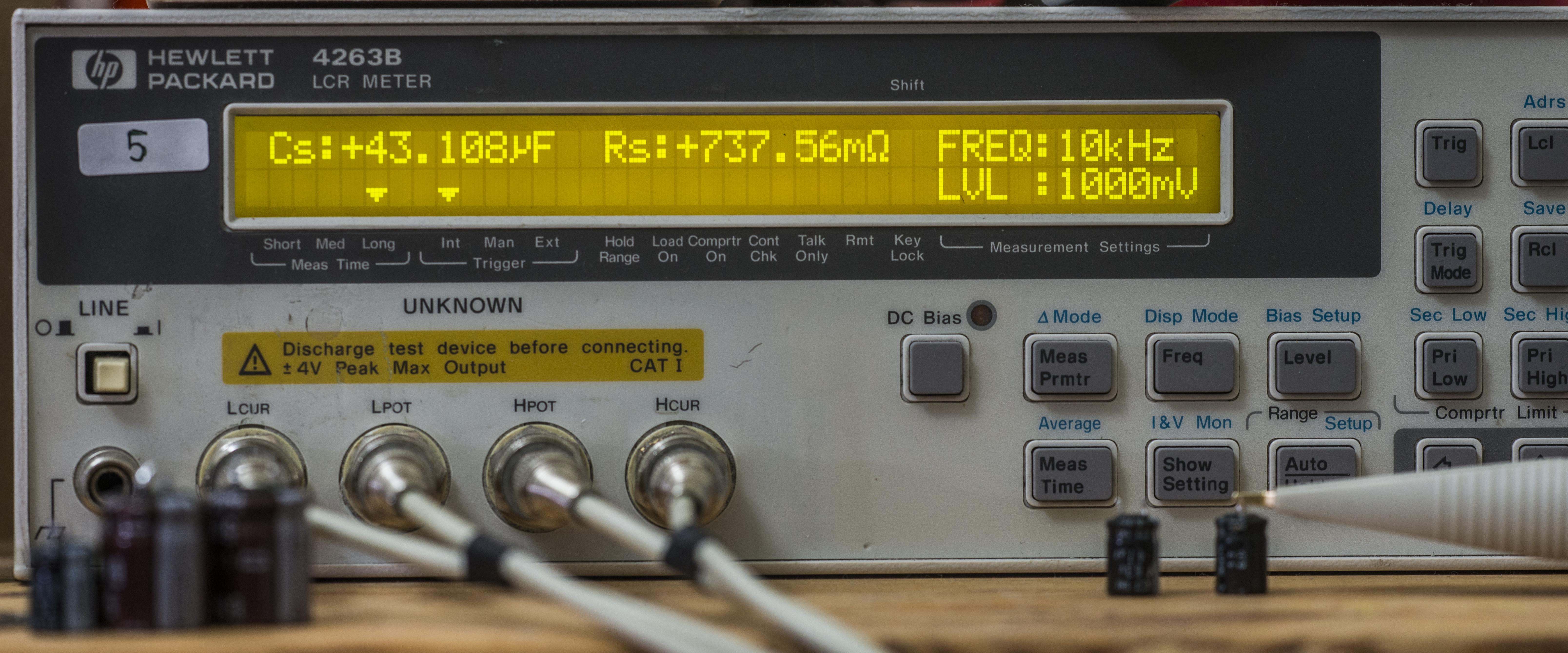
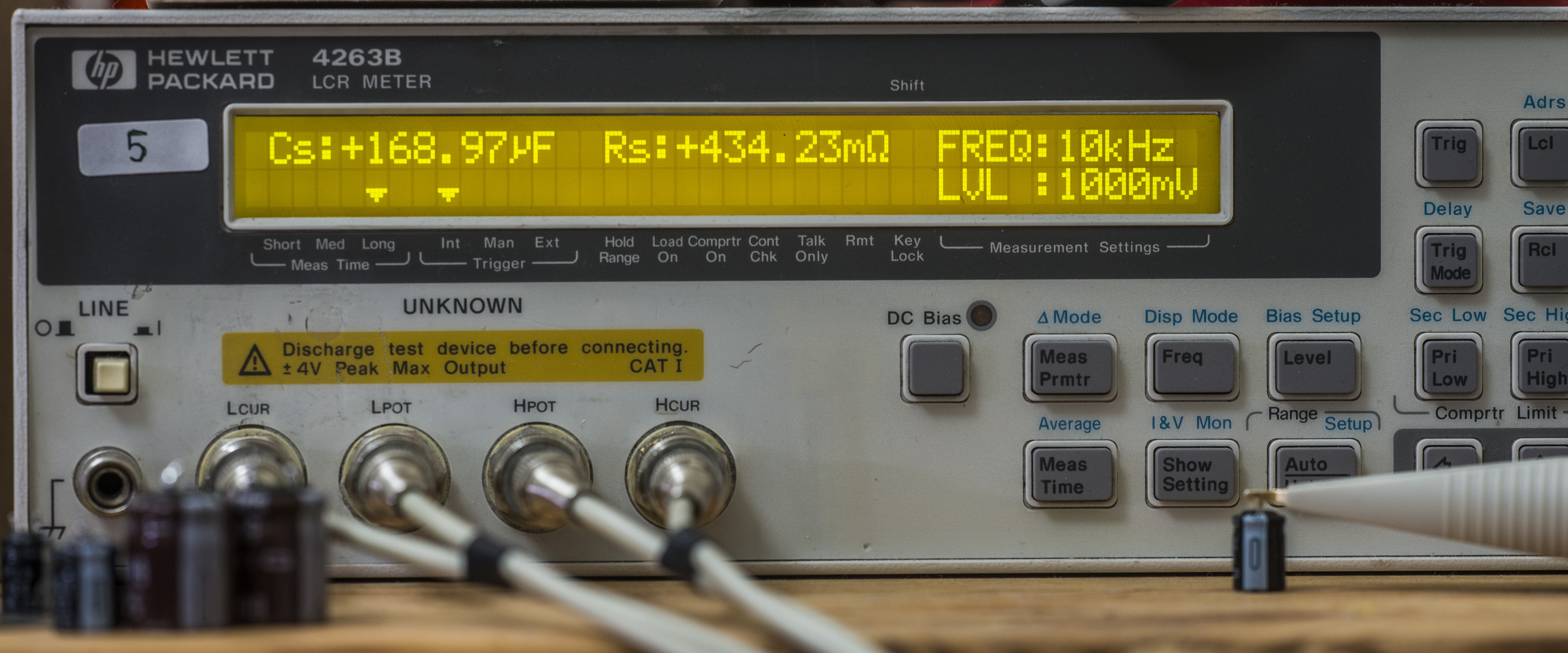

Image 43-48: Capacitor measurements with HP 4263B
It’s a good lesson, capacitors are only getting bad with age, not better as voltage references. 10 years passed? Replace them now!
A5 Outguard Controller

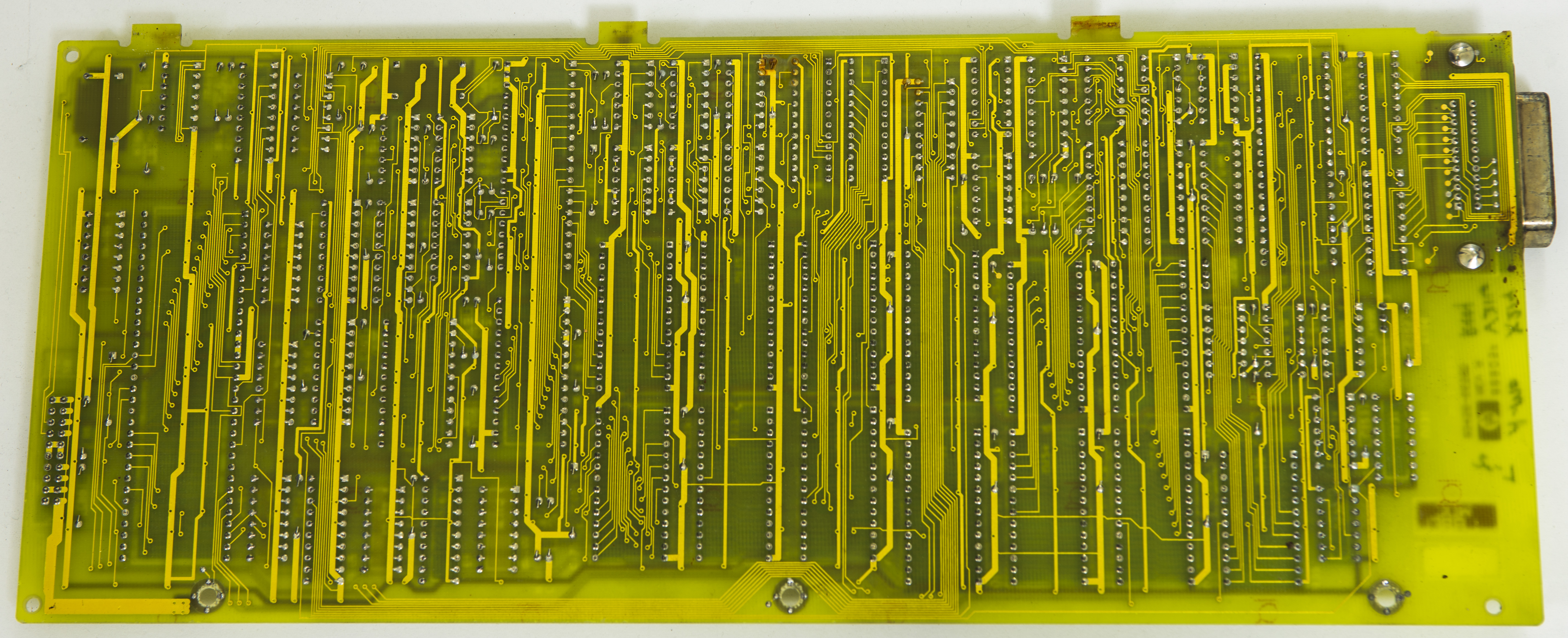
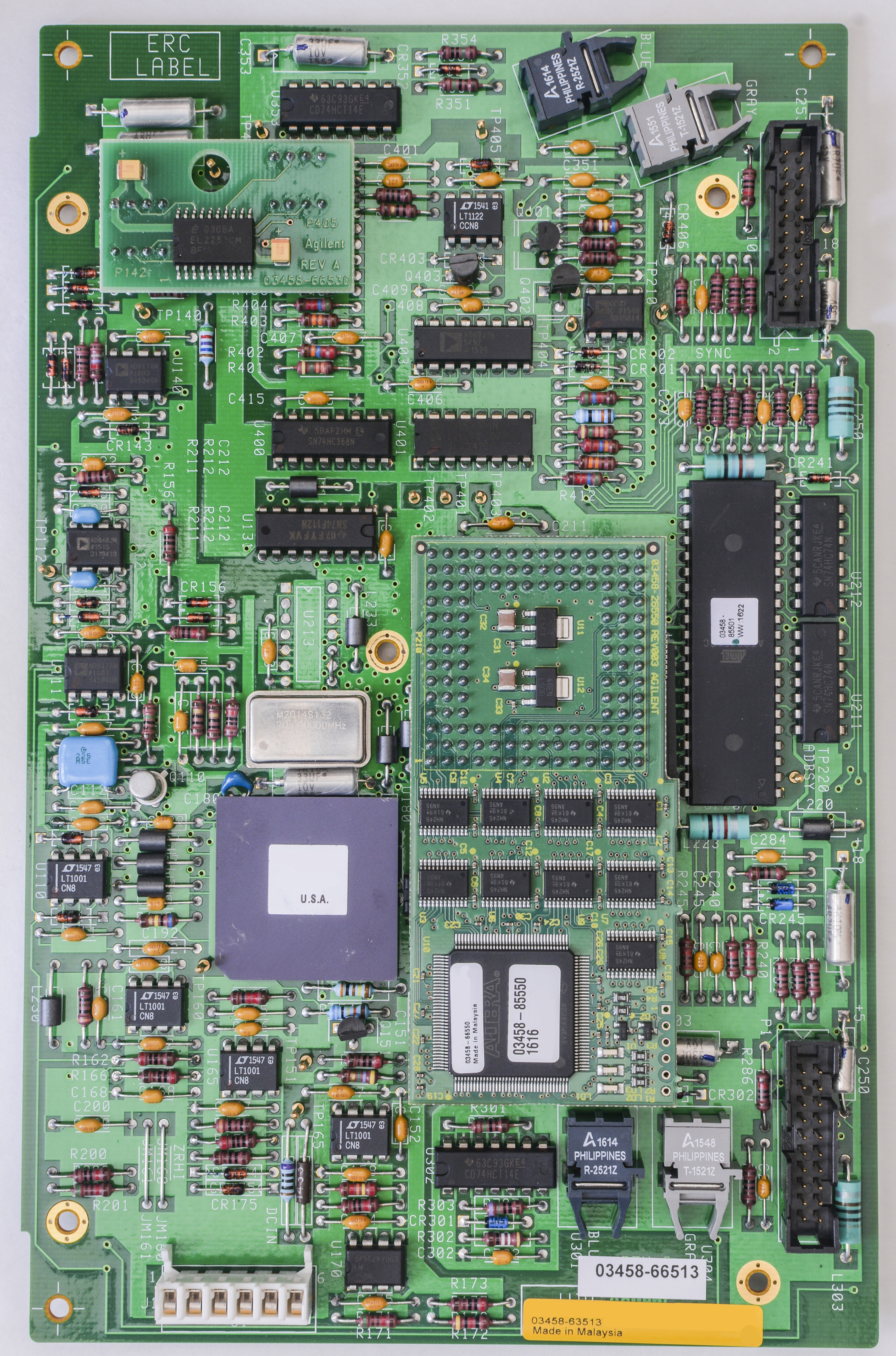
Image 49-50: HP 03458-66505 digital outguard PCB, top and bottom view
Meter digital brain, firmware, calibration ROM and digital interface circuits are located on this dual-layer board. We have older board version with all thru hole components, while newer meters usually have smaller SMT-type A5 controller.
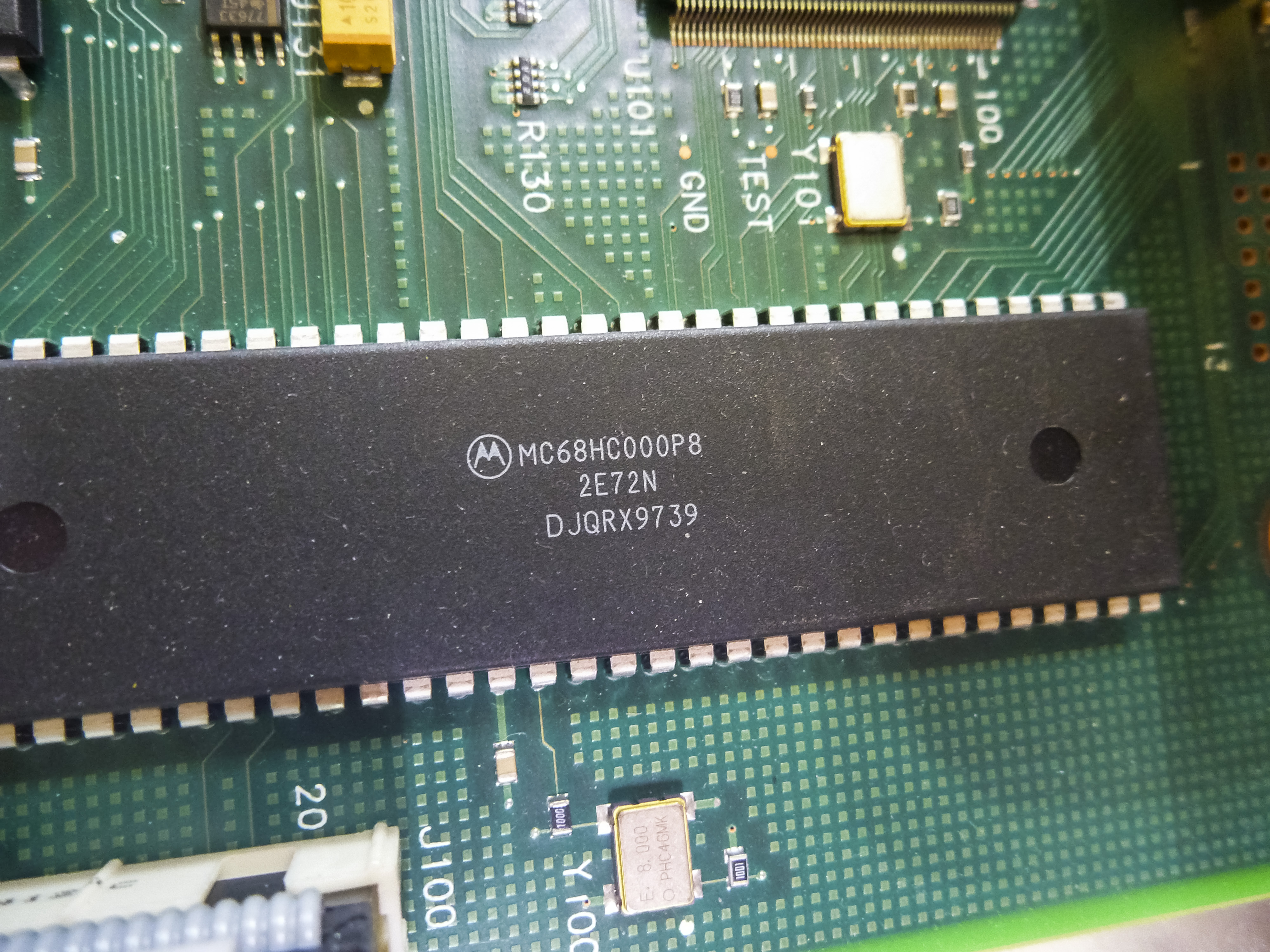
Main processor is infamous 16-bit Motorola MC68HC000P8, 8MHz CISC
Processor’s RAM consist of pair non-volatile Dallas (today it’s MAXIM) DS1235, high and low bytes separately. If these NVRAM become bad, meter during power-on selftest will throw error RAM TEST 1 LOW or RAM TEST 1 HIGH depends on which IC died and lockup further operation.
It’s fully compatible and can be replaced with Dallas (today it’s MAXIM) DS1230Y chips. Original RAM chips are soldered down directly to PCB, so it’s wise to remove old RAMs and solder good quality collet-socket for easy replacement in future.
Calibration data stored in separate NVRAM, Dallas DS1220. I expect that RAM chip dead too, as it’s same age as main RAM.
If your meter still contains valid calibration data, there is a way to read calibration constants back, given that meter can power up and enter operation mode. This message in volt-nut maillist have some details regarding using GPIB commands to readout NVRAM contents.
DS1230 and DS1220 NVRAM is still in production, as can be bought from MAXIM or can replace battery-backed NVSRAMs with Ferroelectric RAM (FRAM) such as Cypress FM18W08 and FM16W08 which does not require battery power to retain its data. Only drawback, that these production FRAM provided only in SOIC package, while obsolete older FM1808 and FM1608 chips had drop-in DIP package version too.
Digital board versions (A5 Outguard Controller)
There are multiple revisions of A5 board assembly in 3458A units over its 25 year lifetime.
| PCBA Version SKU | 03458-66505 Rev.A (66515 Opt.001) | 66505 Rev.B (66515) | 66505 Rev.C (66515) | 03458-66547 or 03458-66548 for Opt.001 | |
|---|---|---|---|---|---|
| |
 |
 |
 |
||
| First released | 1988 | ~2000 | ~2006 | ||
| Option variant | None and 001 for extended memory | ||||
| RAM type | 2 x DS1235, for low and high bytes | SnapHat NVRAMs + SRAM | |||
| Calibration RAM type | 1 x DS1220, for calibration data | SnapHat NVRAM | |||
| User-replaceable batteries | No | Yes | |||
Table 4: A5 PCB versions
I happen to have oldest A5 PCB, but with community help we can take a look on more recent revisions of A5 PCBA used in 3458A’s.
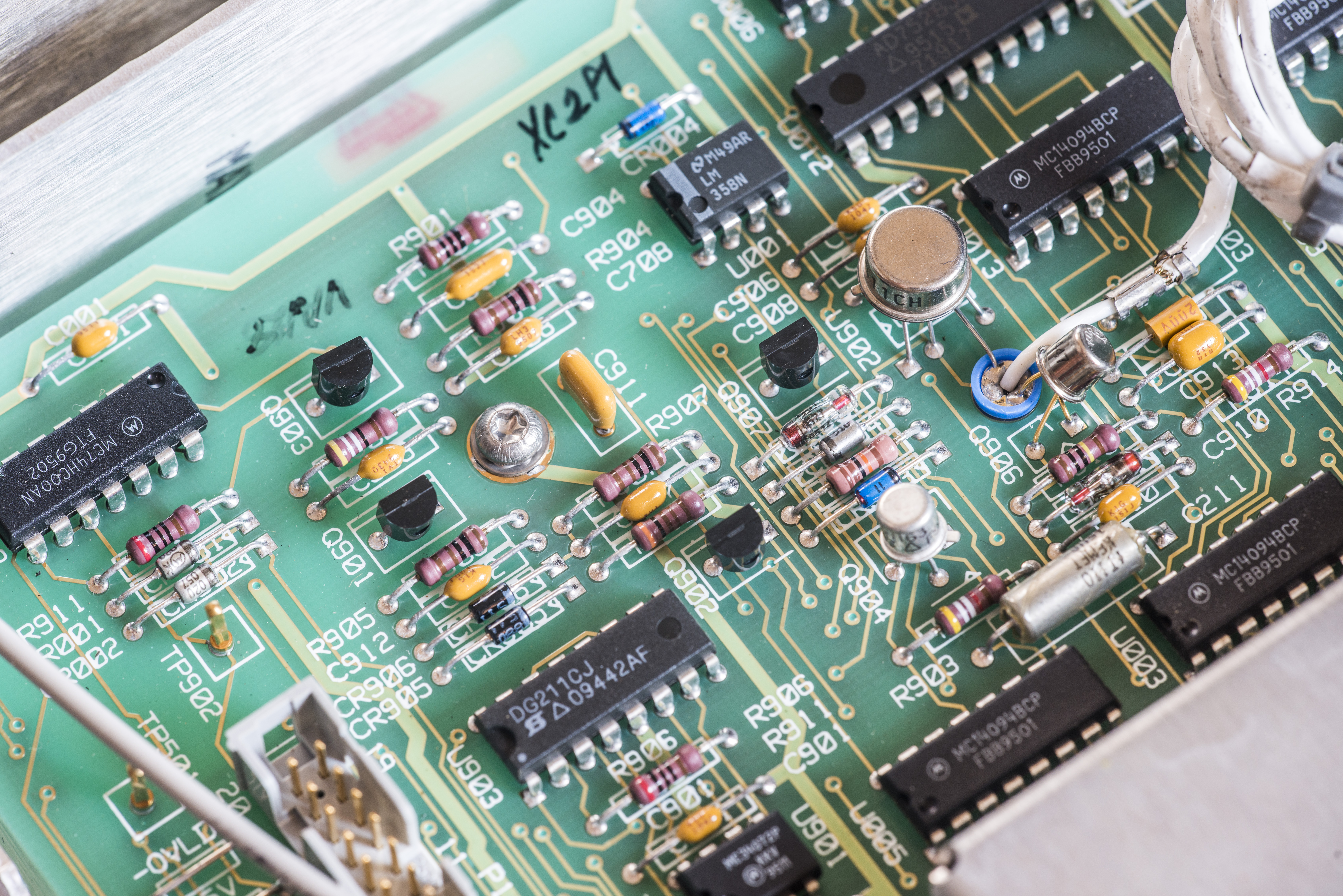
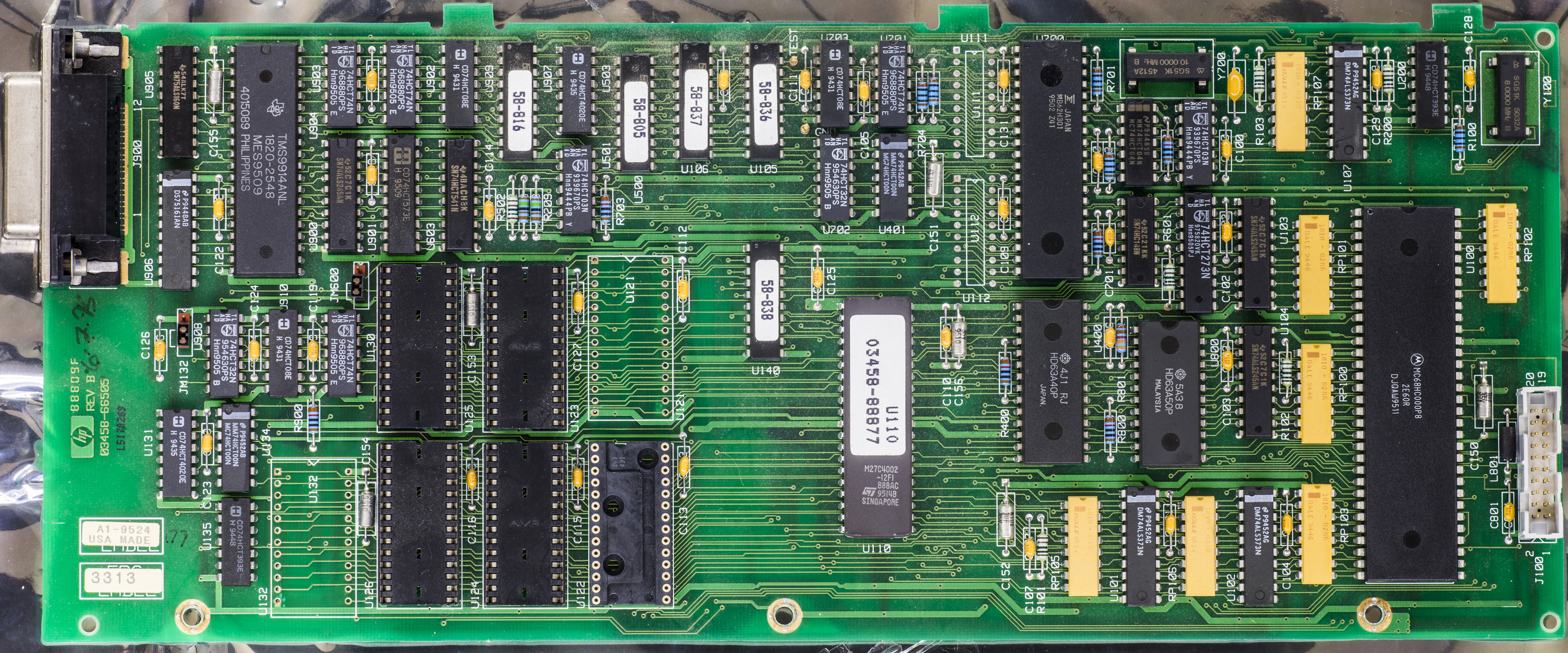
Dr.Frank, well-known enthusiast shared nice hi-res photo of year 2000 A5 PCBA:
As it’s visible from the photo, six firmware ROM chips got replaced with larger ST M27C4002, holding single binary image. SRAM and calibration NVRAM are same as older Rev.A.
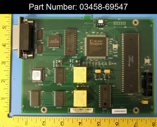
For latest 03458-66547 version of A5 PCB, other electronics video blogger, Martin Lorton also contributed some nice hi-resolution photos of his newer 03548-66548 A5 board, so we can check details and parts on it:

Board is redesign to reuse modern components but fully compatible firmware-wise. Obviously Agilent did not want to mess up any magic souce might be present in firmware, so it’s same Rev.9 code.

Processor is same Motorola MC68HC000P8, made in 1997, while rest of parts on board have date codes from 2004. Obviously, HPAK got plenty of stock for these 68HC000 processors on hand to just reuse them in redesigned board.
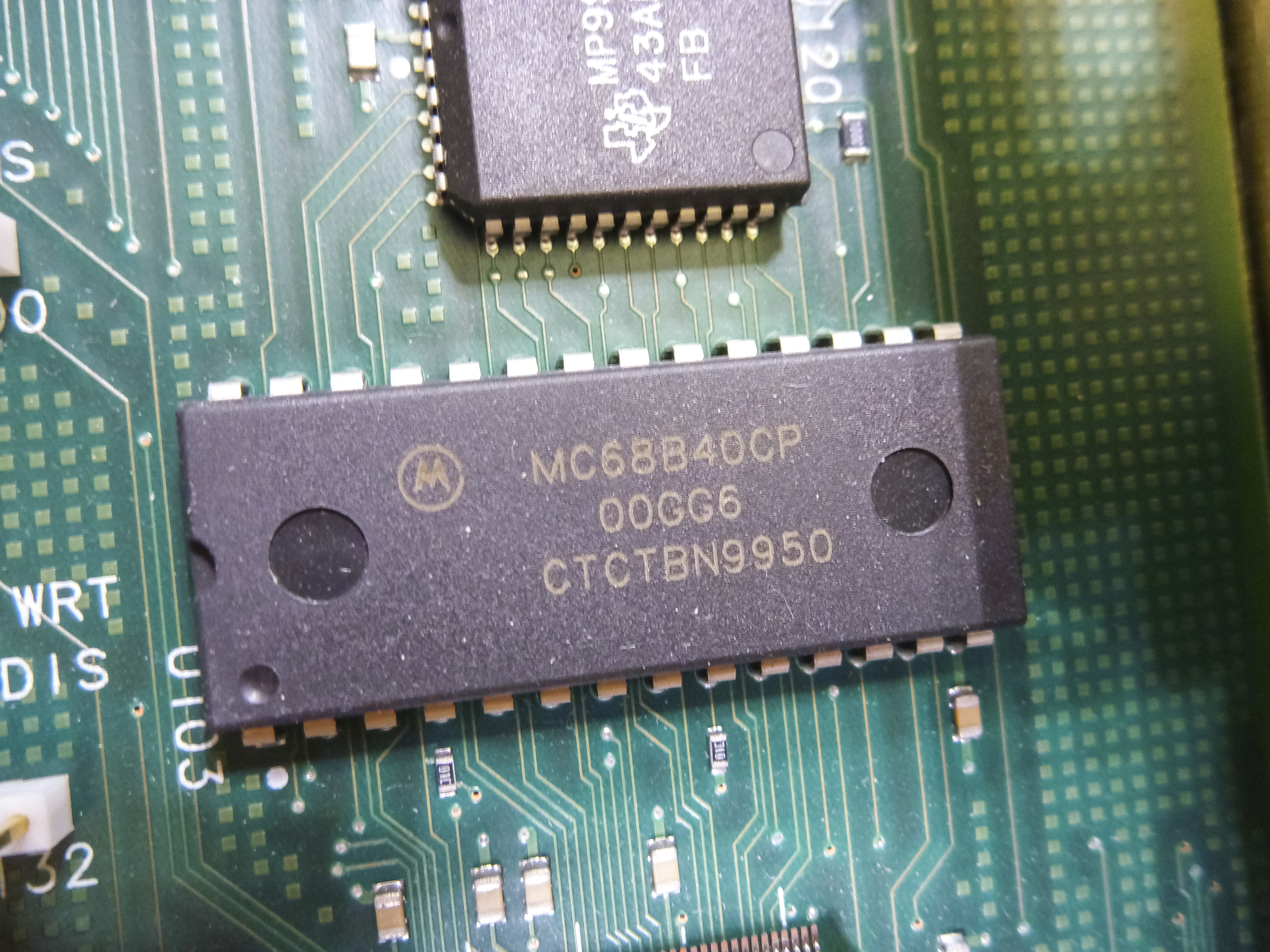
All digital glue logic, spotted in number of DIP packages on older A5 boards is now moved to Xilinx Spartan-II XC2S30 in PQFP-208 package. This little FPGA have 972 logic cells (30K gates), have 92 I/Os and 24K of onboard RAM. There is another Motorola chip still present on board, MC68B40CP.


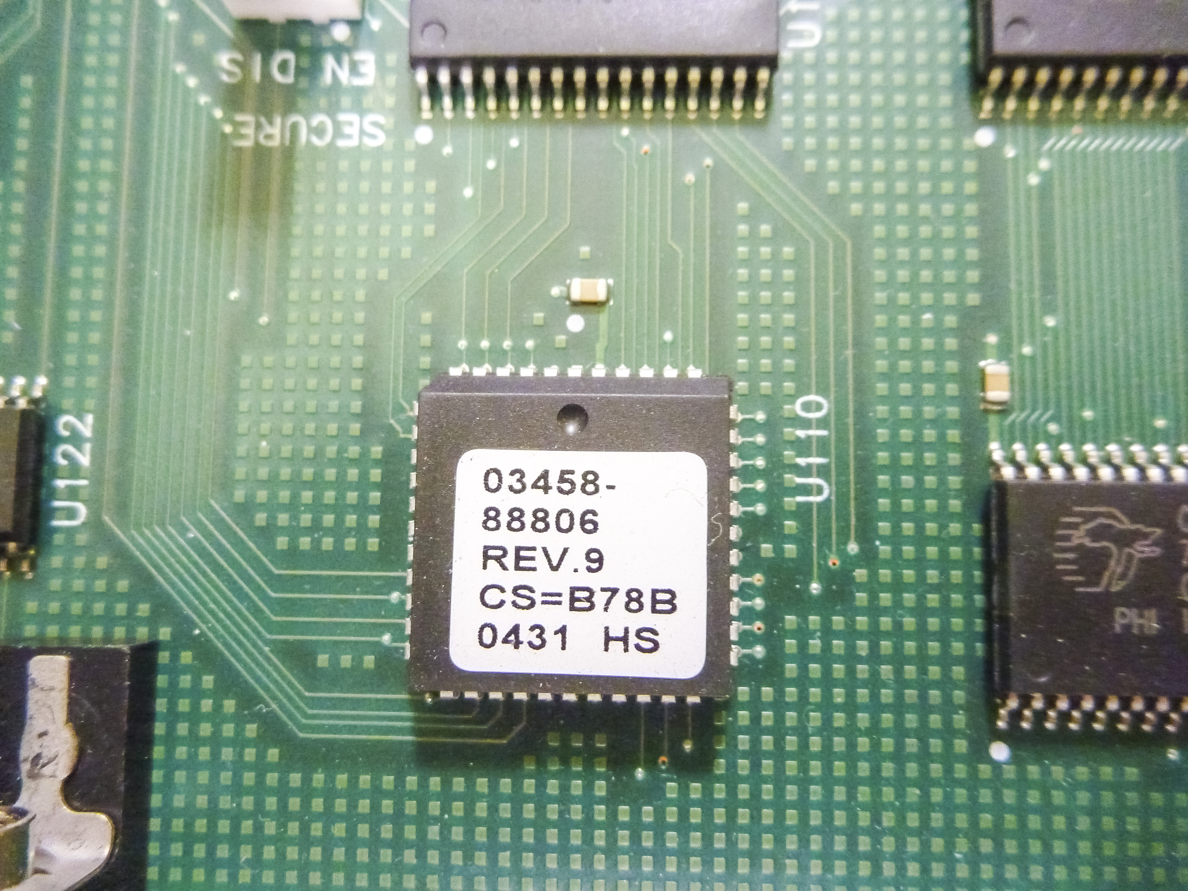
GPIB Interface controlled is well known popular MP9914FNL controller with Texas Instruments 75ALS161 and 75ALS160 XVRs. Firmware ROM 03458-88806 Rev.9 is stored in single PLCC chip, soldered directly to the PCB.
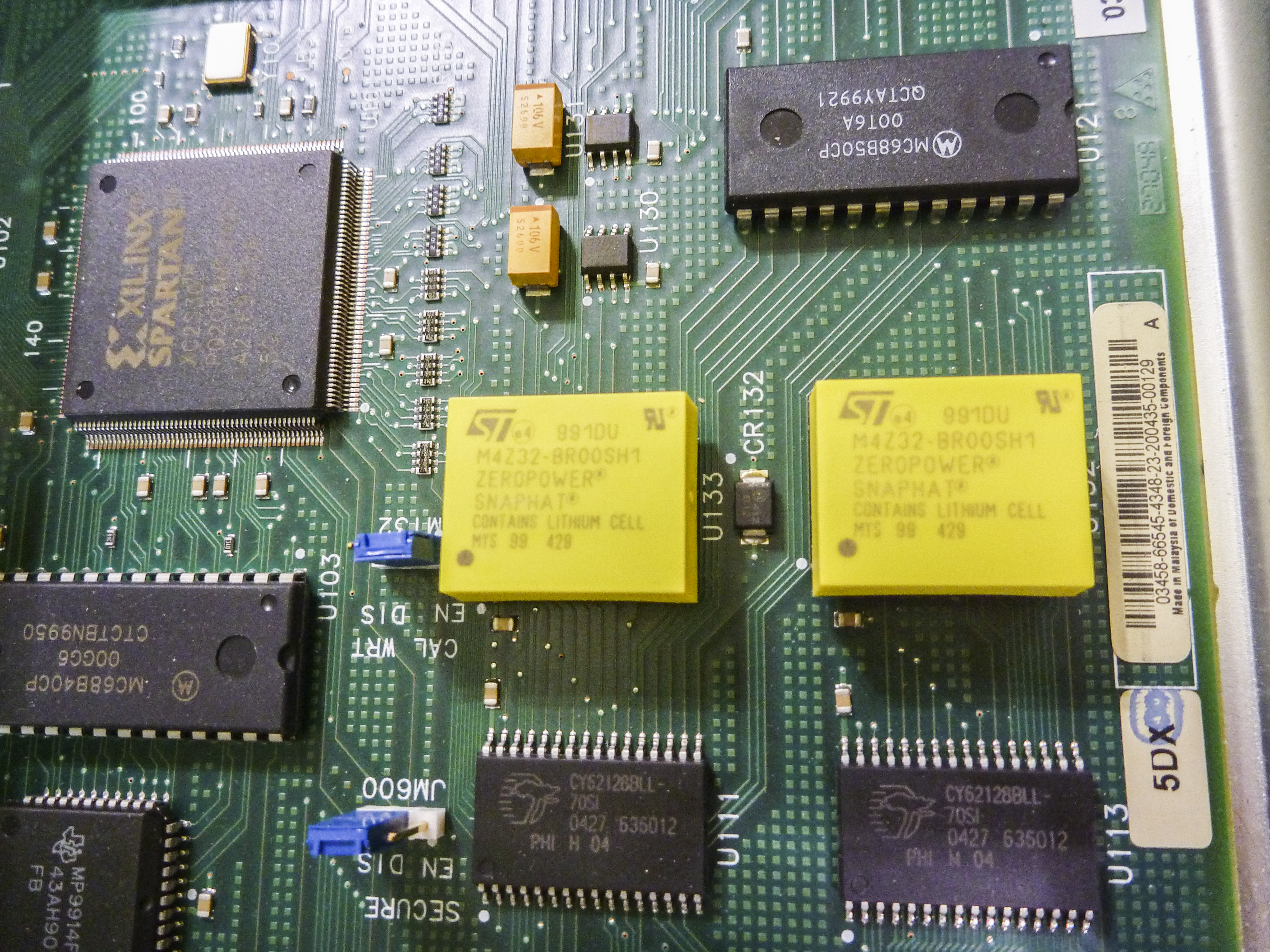
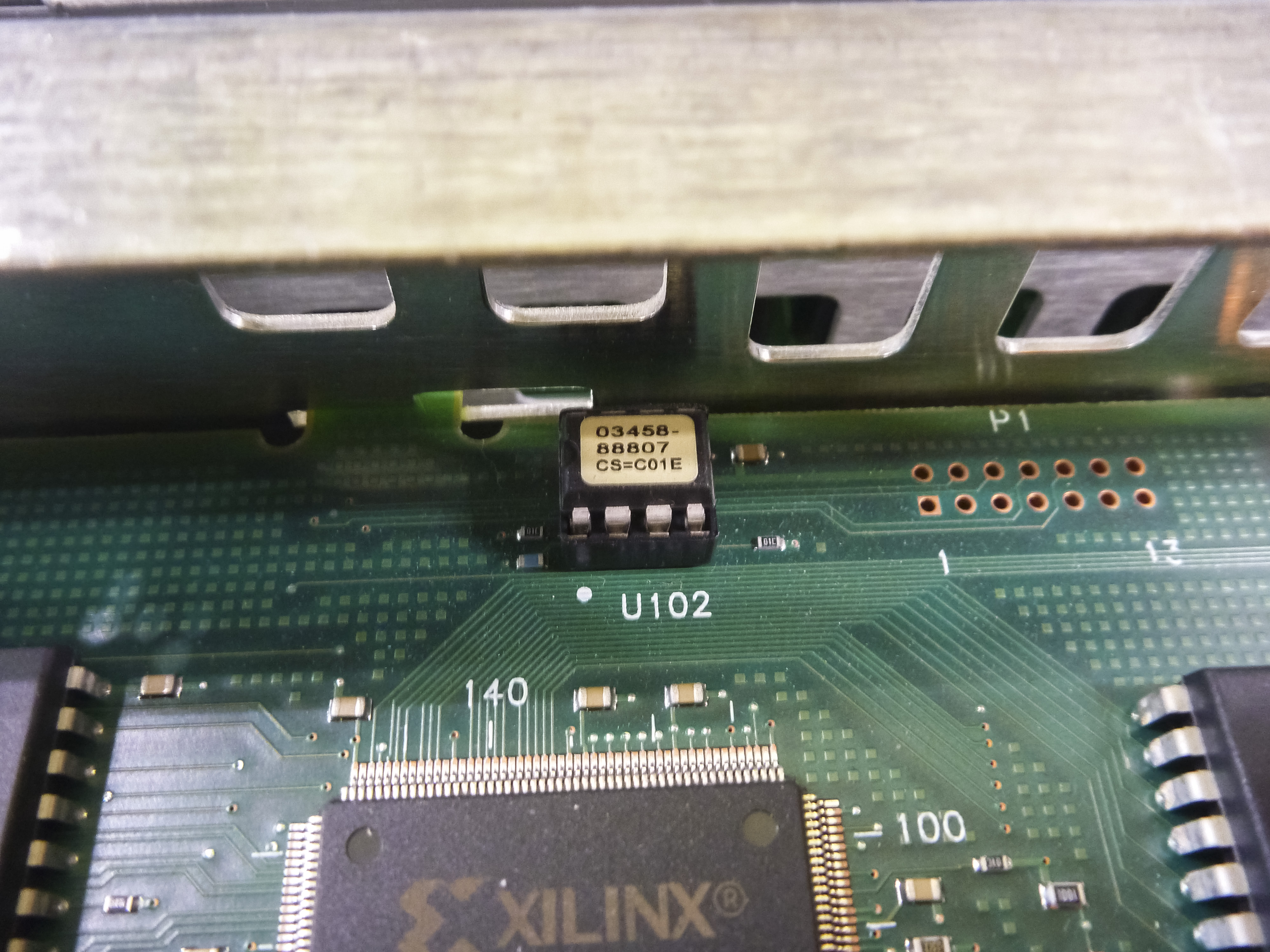
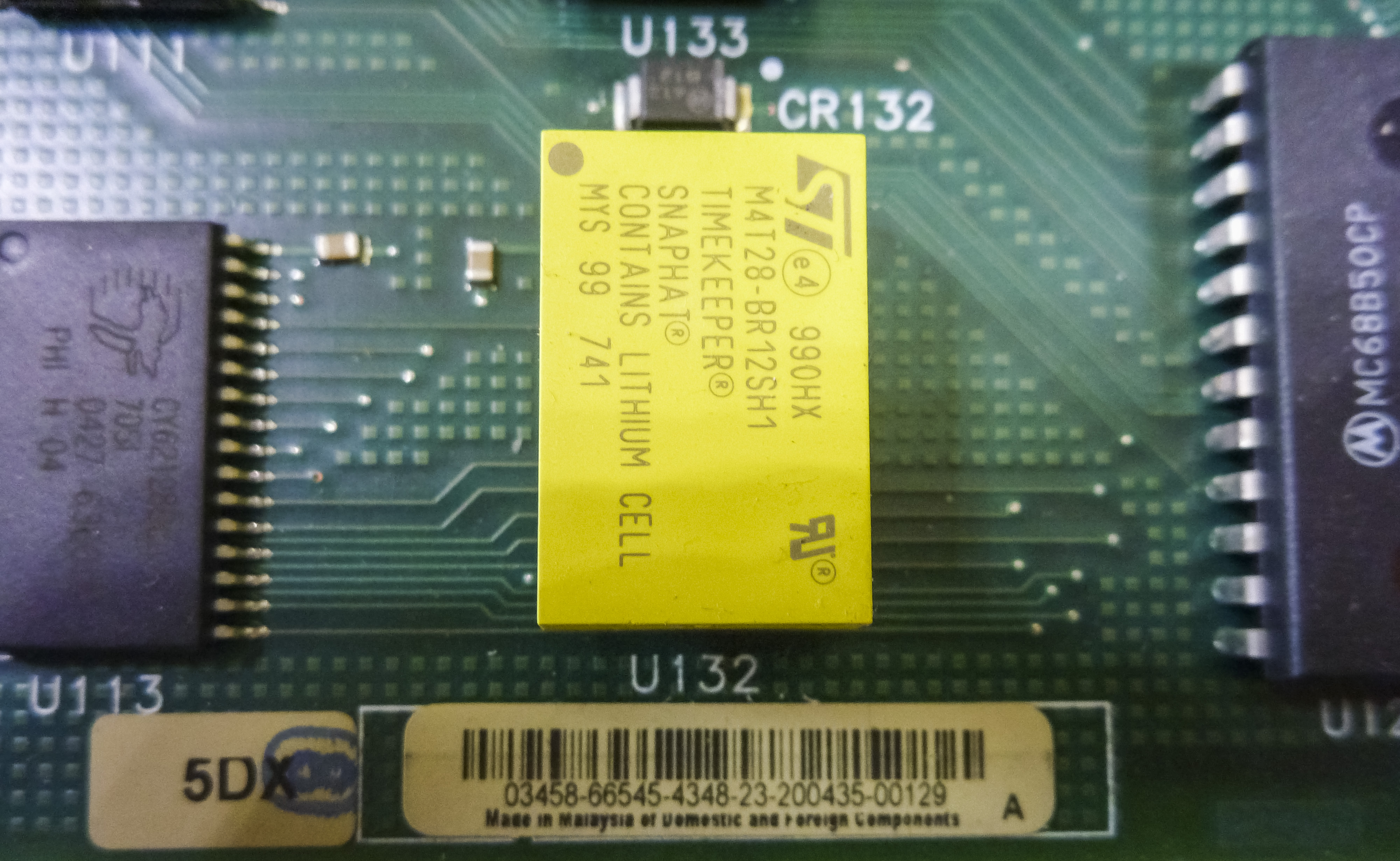
There are three SRAM packages, made by Cypress CT62128BLL-70SI, and pair of NVRAM chips with ST SnapHat Lithium batteries in them. Calibration NVRAM is stored in backed RAMs, so make sure to replace these after 6-8 years to be on safe side and prevent calibration data corruption. Replacement procedure is simple – while keeping unit is POWERED ON, remove old yellow caps and replace with new ones. Hidden 8-pin DIP U102 IC with firmware sticker 03458-88807 on it retain FPGA bitstream.
He also have nice video covering his 3458A here on YouTube channel. Be sure to check it out.
Older units with 66505/66515 boards can be retrofitted with the newer version A5 PCBA by ordering Agilent/Keysight Update Kit p/n 03458-80047 (around $600 USD) or extended memory Kit p/n 03458-80048 (around $1000 USD). There is Service note 3458A-19A covering this upgrade.
Repair for A5 board
STEP 1. NVSRAM
As described earlier, failure of main memory NVRAM chips will instantly generate RAM TEST 1 LOW or RAM TEST 1 HIGH, so that is exact problem we have in our case.
I used copper solder wick to suck solder from NVRAM pins and remove faulty chips from PCB. Instead of soldering new chips in place, I opted to solder good quality gold-plated collet sockets, so in future soldering would not be required.
Same did for calibration NVRAM chip, DS1220, position U132, as that one is also very old. After meter repair and calibration, data stored in that chip will be critical. You don’t want risk losing those constants after expensive calibration.
Tested original chip from board and was surprised that actually it does have correct-looking data and pass read/verify tests on my MiniPro TL866 programmer.
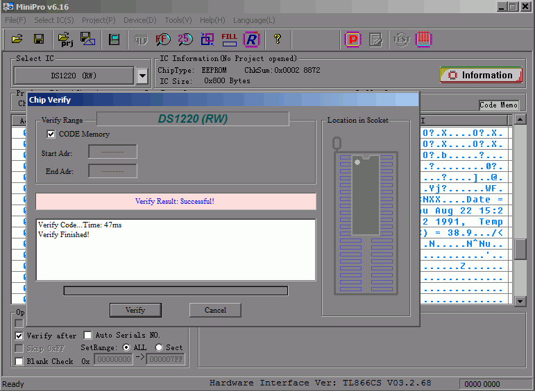
Image 51: Calibration ROM readout, still OK!
Date of calibration recorded in plain ASCII, saying 1991 year. This makes it rather useless, as in 24 years resistors and parts in meter drifted more than such old data could be used, as original DC reference board is missing. But since we have nothing better, I will copy this data into new Dallas DS1220 so we can use it as starting point.
After replacement of Dallas NVRAM, and powering up only A5,A6 and front panel I can see it passing RAM test, checksum test and display now shows ISOLATION FAILURE message, just after few seconds of running HARDWARE TESTING. Of course, that is due we have nothing else connected, and processor expects data from analog side.
STEP 2. GPIB port
My board also fall within range of Service note 3458-13A : GPIB Communication Failures Using the 3458A, so I will add jumpwire for better ground on GPIB connector. There is interesting open connection routing with open mask on top side of PCB, just near connector pins.
I also replaced GPIB connector, as original one is really rusty. New GPIB connector was used from broken HP 33120A PCB.
Since I bet all of you already tired watching multimegabyte photos, let’s do something different this time around:
Video 1: Timelapse video of HP 3458A restoration in progress
5 hours worth timelapse, one shot every minute, 4K resolution, using my repaired Nikon D3. 526 photos, total.
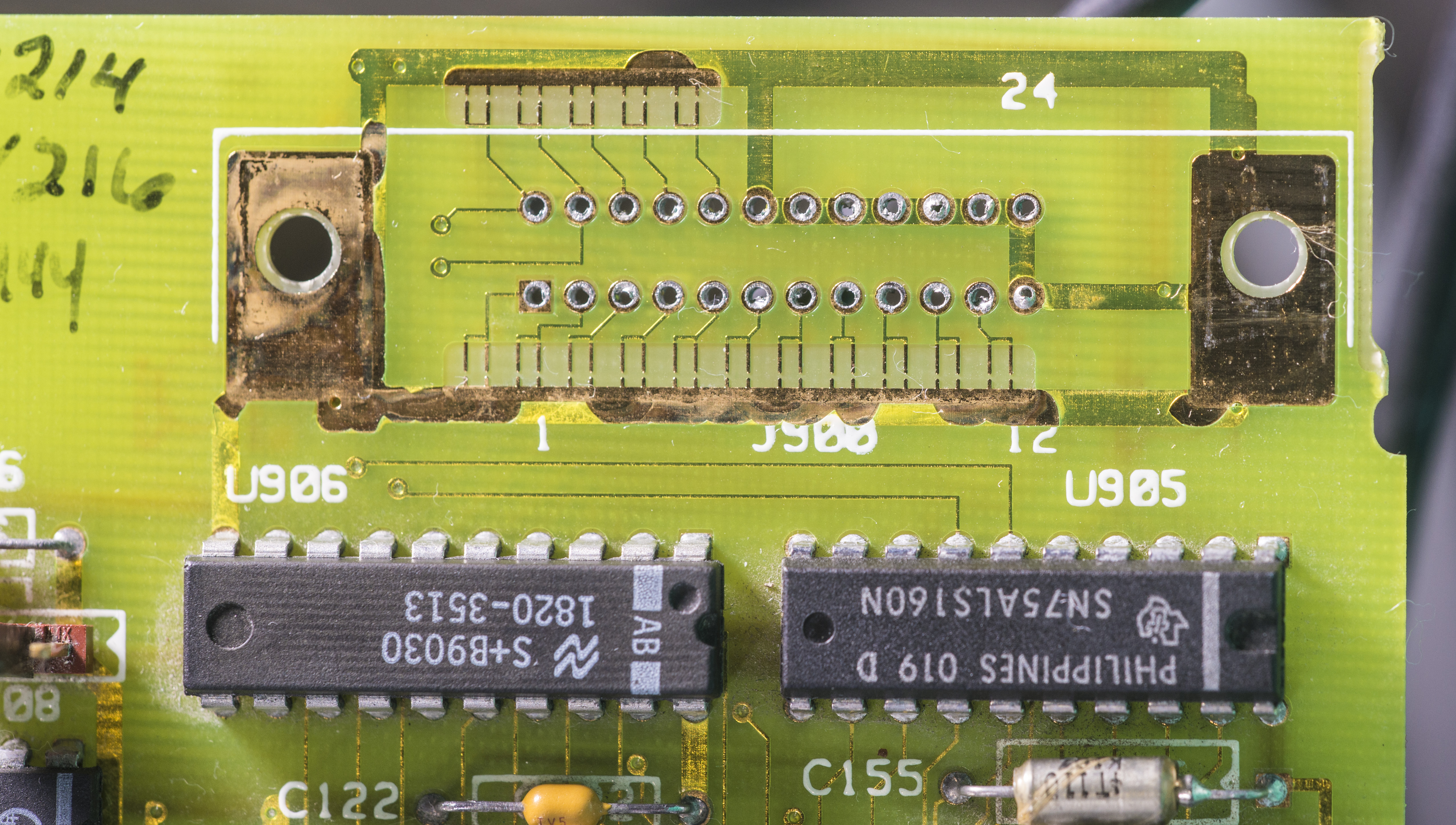
Image 52: GPIB connector footprint with ESD spark-gaps
Quiz for readers : what are those funny traces with cutout do? :-/O
After connector replacement (had to saw it a bit, as it’s mounted to PCB using rivets!). No, I don’t have a drill, so used hand mill instead.
Then boring part, water+IPA bath for PCBA:
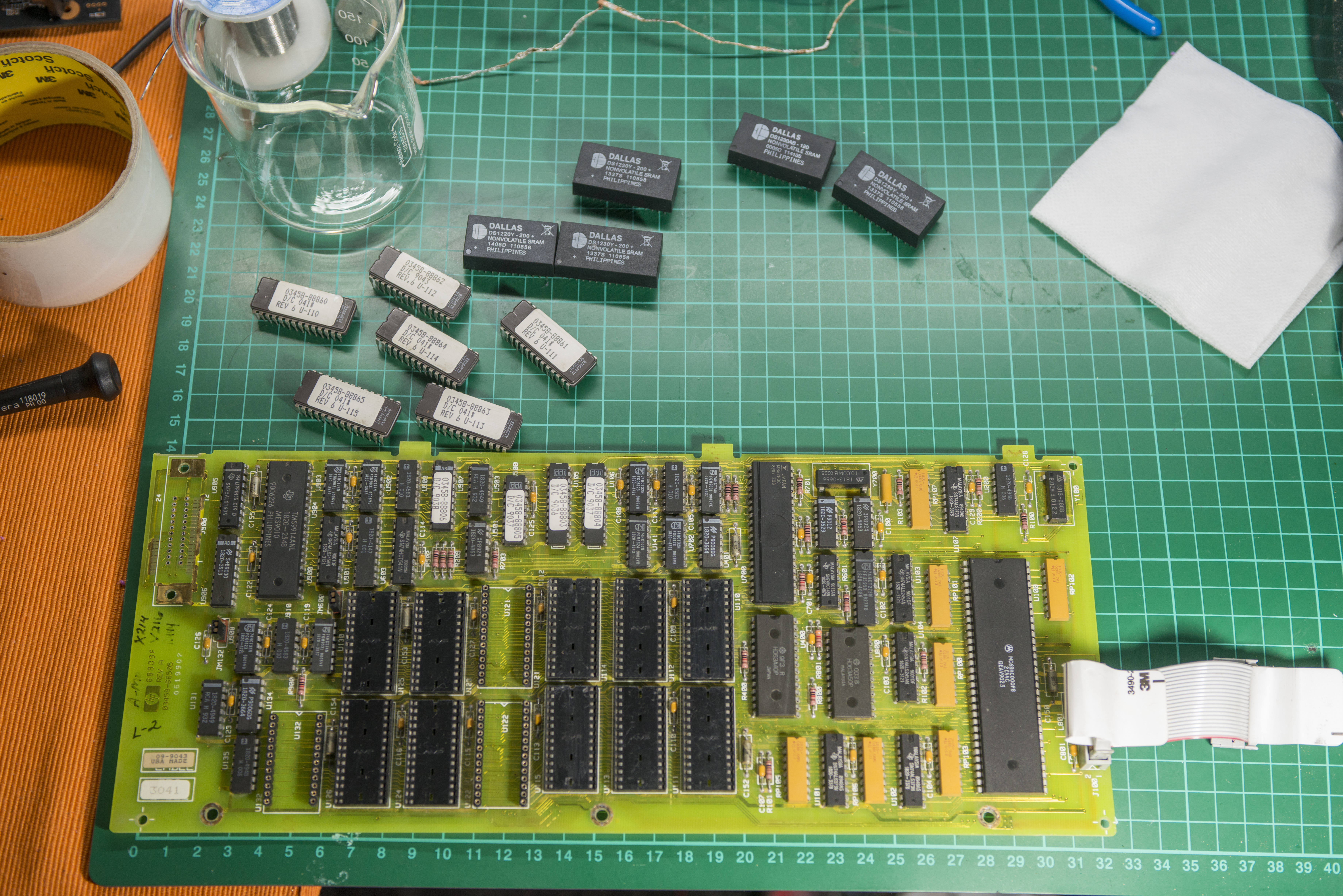
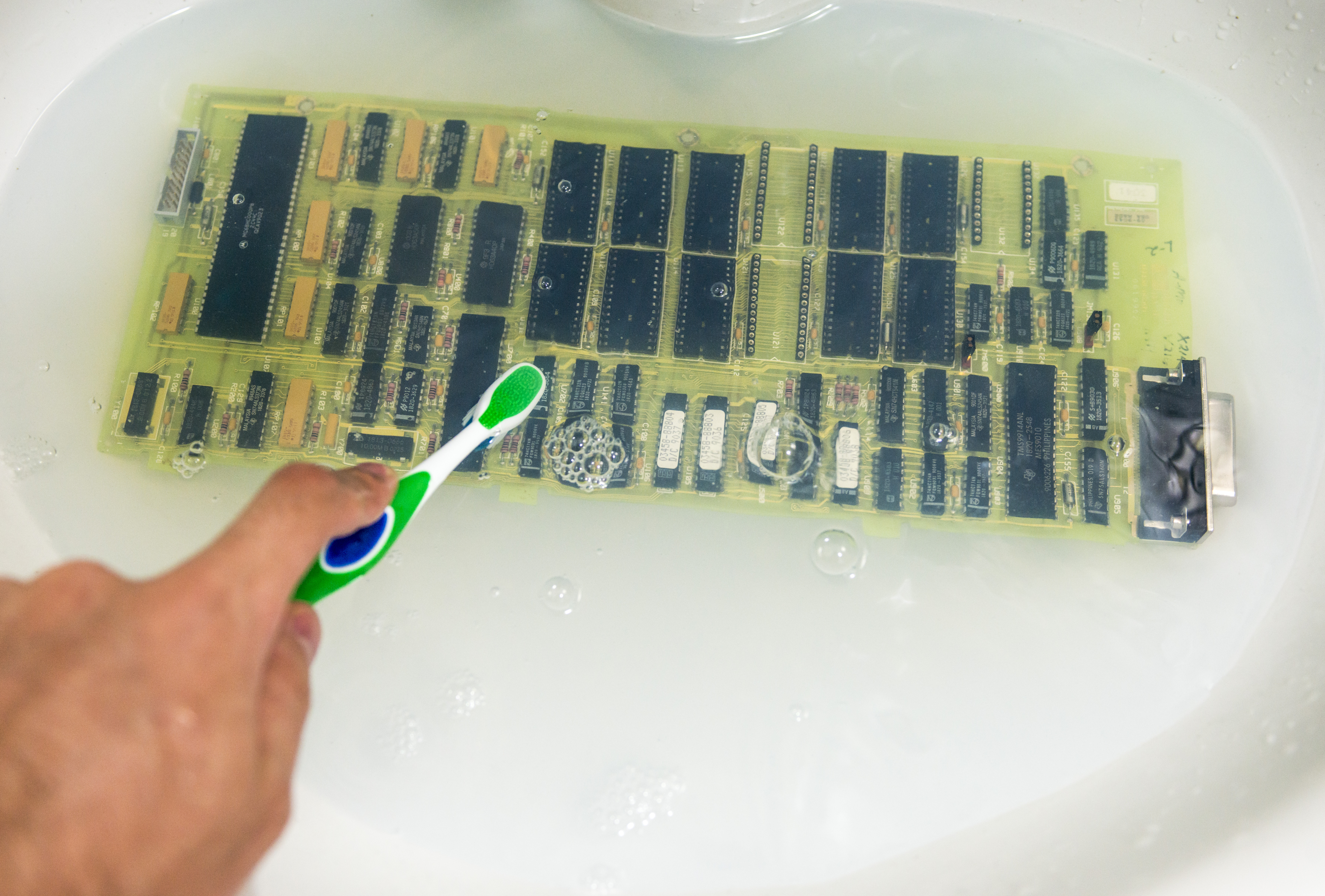
Image 53,54: NVRAM retrofit and cleaning PCB in IPA+water bath
A4 Inguard power supply
This board rectify secondary voltages from main transformer T1 connected via 5-contact P1 into DC voltages for analog board’s power.
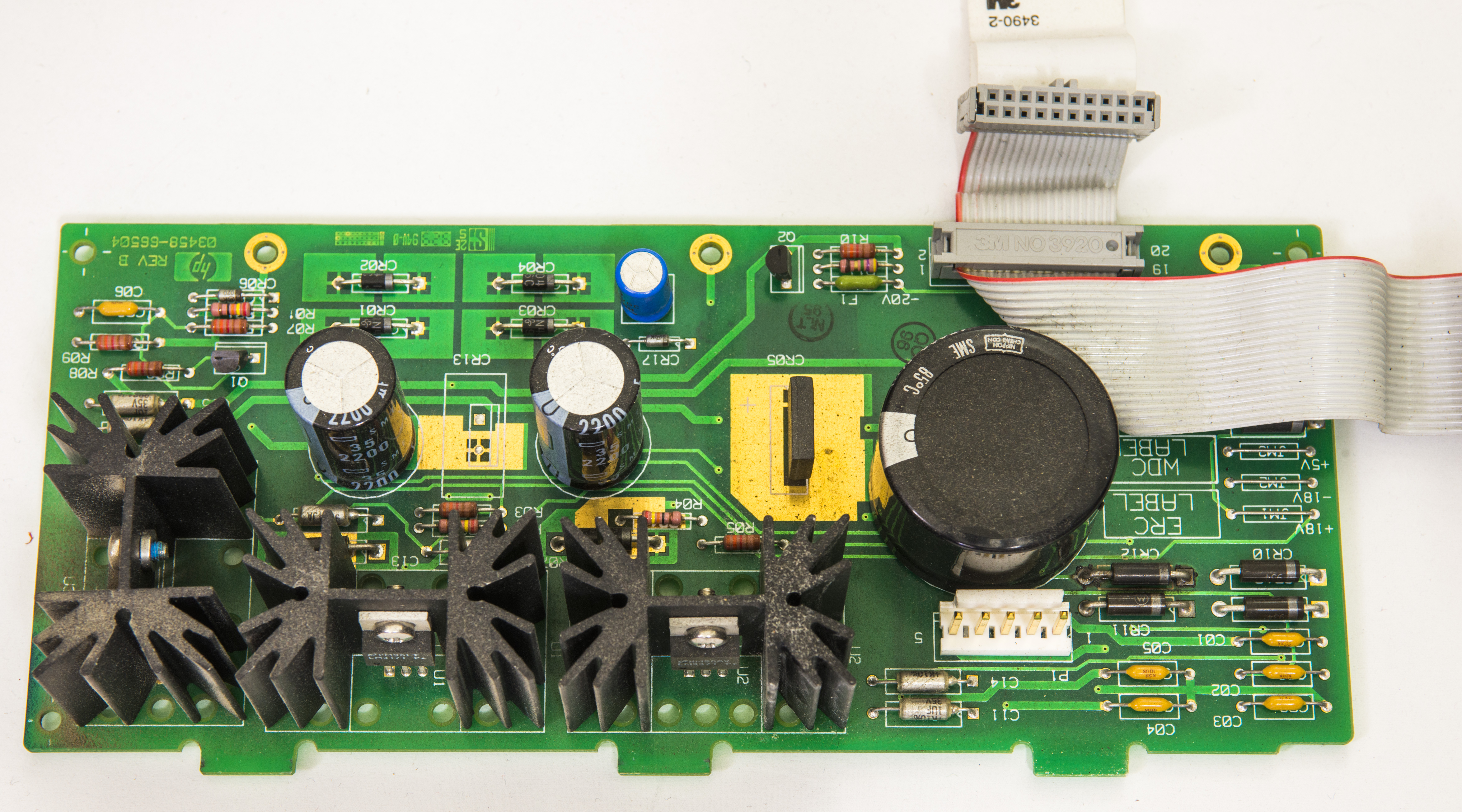

Image 55,56: Inguard power supply 03458-66504 board, top and bottom view

Image 57: A4 PCBA Schematics from CLIP
Let’s look on transformer first.

Image 58: Broken transformer, disassembly attempt
Transformer have winding sections, with separate two bobbins, primary with secondary Outguard +5V rail (goes to digital board and front panel, so that’s working).
Second section for Inguard supply is inner bobbin with two secondary windings (one with center tap to generate +18/-18 and second for +5V analog supply).
Each winding have its own metal inner shield to reduce leakage and coupling between different transformer sections. Each of those shields have separate wire connected to different locations at Outguard and Inguard chassis frame points.
Windings in my transformer are shorted together, which is clear from simple DMM resistance check!
This could be a result of 220 VAC is applied, while rear line voltage selection switches are set for 120 VAC.
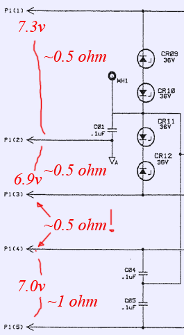
Image 59: Windings measurement on transformer
I would not trust repaired/rewinded transformer in such an instrument anyway, so we going to make Keysight richer for $337 $429 USD. That’s new transformer cost.
2 weeks later…
Now, new transformer arrived and we can measure both failed old one and new to provide comparison measurements, so this will help owners of dead 3458A’s to diagnose theirs units.
| Voltage rail name | Nominal spec | Regulator | Bad transformer in our unit | New good transformer winding |
|---|---|---|---|---|
| +18V | +18VDC | U1, LM317T | Vmeas : 7.3 VAC, 0.5 Ω | Vmeas : 20.1VAC, 1.42 Ω |
| -18V | -18VDC | U2, LM337T | Vmeas : 6.9 VAC, 0.5 Ω | Vmeas : 20.1VAC 1.42 Ω |
| PSS | return for +-18VDC | Vmeas : 14.2 VAC, 1.0 Ω | Vmeas : 40.1VAC 2.88 Ω | |
| Resistance between ±18V winding and +5V | 0.5 Ω | >10 GΩ | ||
| -18unreg | CR01-CR04 diode bridge | |||
| +5V | +5VDC | U3, UA7805 | Vmeas : 7.0 VAC, 1.0 Ω | Vmeas : 9.1 VAC |
| -20V | -20VDC | CR17 zener + Pass PNP Q2 | ||
| Resistance between ±18V winding and secondary shield | 0.8 Ω Shorted ! | >10 GΩ | ||
| Resistance between ±18V winding and secondary 5V shield | >10 GΩ | >10 GΩ | ||
Table 6: Inguard power test results
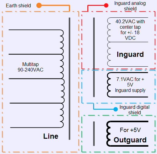
Image 60: Transformer schematics
Repair for A4 board
Now we can look on A4 PCBA, and quickly spot visible damage occurred on zener diode CR11. Quick measurement indicated that diode is dead shorted, as well as CR12. These IN5365B 36V Zeners rated for 0.4W power and function as overvoltage protection clamps before linear regulators.
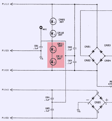
Image 61: Broken protection zeners on A4 PCBA
In case of voltage presence over rated zener’s 36V, diode will start conducting, directing current flow into ground, and limiting voltage on protected rail.
Zener’s are connected back-to-back, to limit both sine wave sides, forming variant of TVS device. It is nice to see these protection parts in design, instead of hoping that transformer will never supply unexpected higher voltage. A thing to learn for young engineer generation ;-)
There are also output zener protection and CR06 for +5V supply. These diodes are OK.
Now, since we still wait for new transformer to arrive, how can we test Inguard supply to confirm it’s OK? Glad you ask, I have a solution. From previous Keithley Model 2001 repair projects I have one extra power transformer, which happen to have same voltage outputs, as HP one, just at lower power rating. But since we connect only Inguard supply A4 board, we don’t need full power to check LDO’s operation. Let’s replace blown zeners and test A4 PCBA with properly wired Keithley mains TR-280 transformer. Never know which parts could ever come handy, eh?
But first, replaced original CR11,CR12 with fresh zeners (got 50pcs from eBay, just few dollars with free shipping).

Image 62: New zeners ready for replacement
Cleaned board both sides, everything else look intact and good.

Image 63: Test with Keithley power transformer
Warning! These procedures involve working with line mains voltage, so be careful and pay attention of what you doing, to avoid electric shock!
Now we can connect input IEC plug socket to transformer’s primary (since I need 110VAC, I used WHITE + BLACK wires).
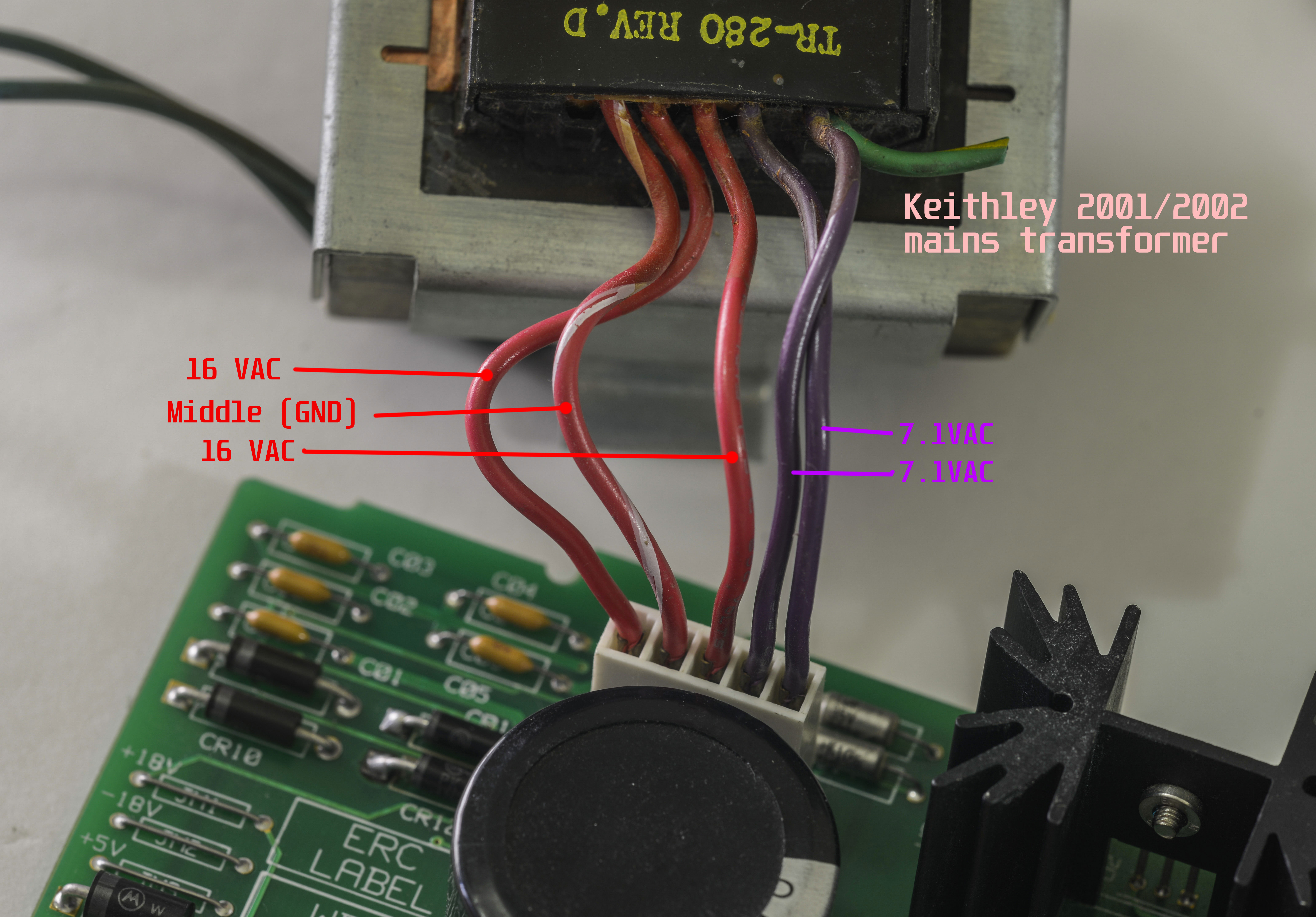
Image 64: Wiring of secondary side on Keithley TR-280 transformer
Keithley used same type of 5-pin connector, but with different pin out. Secondary connector need rewiring as on photo above. I powered transformer separately and measured VAC voltages on secondary, without A4 board connected, to make sure all voltages correct.
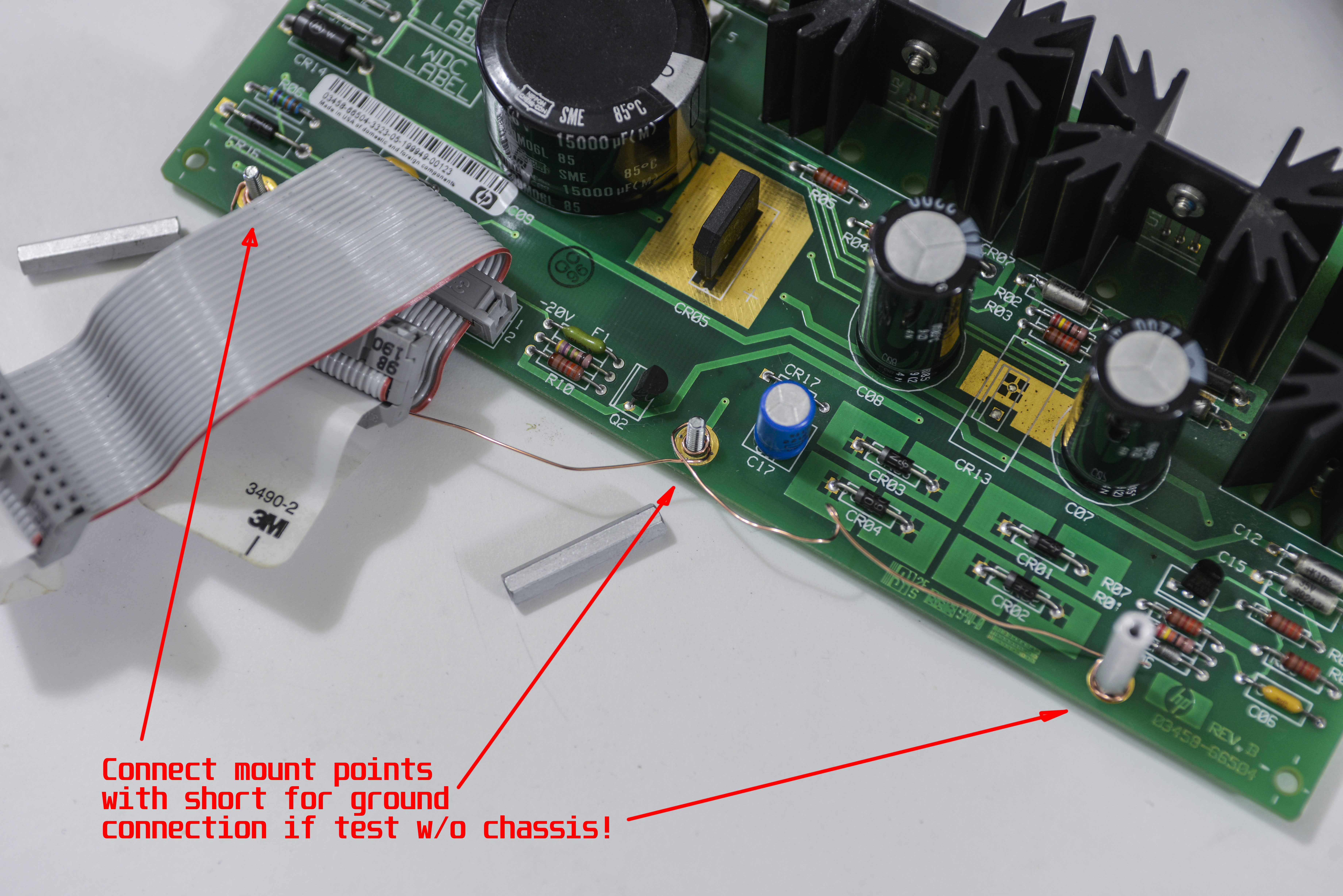
Image 65: Ground connections
If you see schematics of A4 board above, you may notice MH1, MH2, MH3 connections. These are connected directly to guard frame in 3458A’s chassis, which is acting as Mecca star point for GND potential. Since I testing board separately, not mounted to chassis, I needed to connect these MH* points together with copper wire. This will be our ground point for measurements as well.
Apply power to transformer, and if nothing smokes, test output DC voltage.
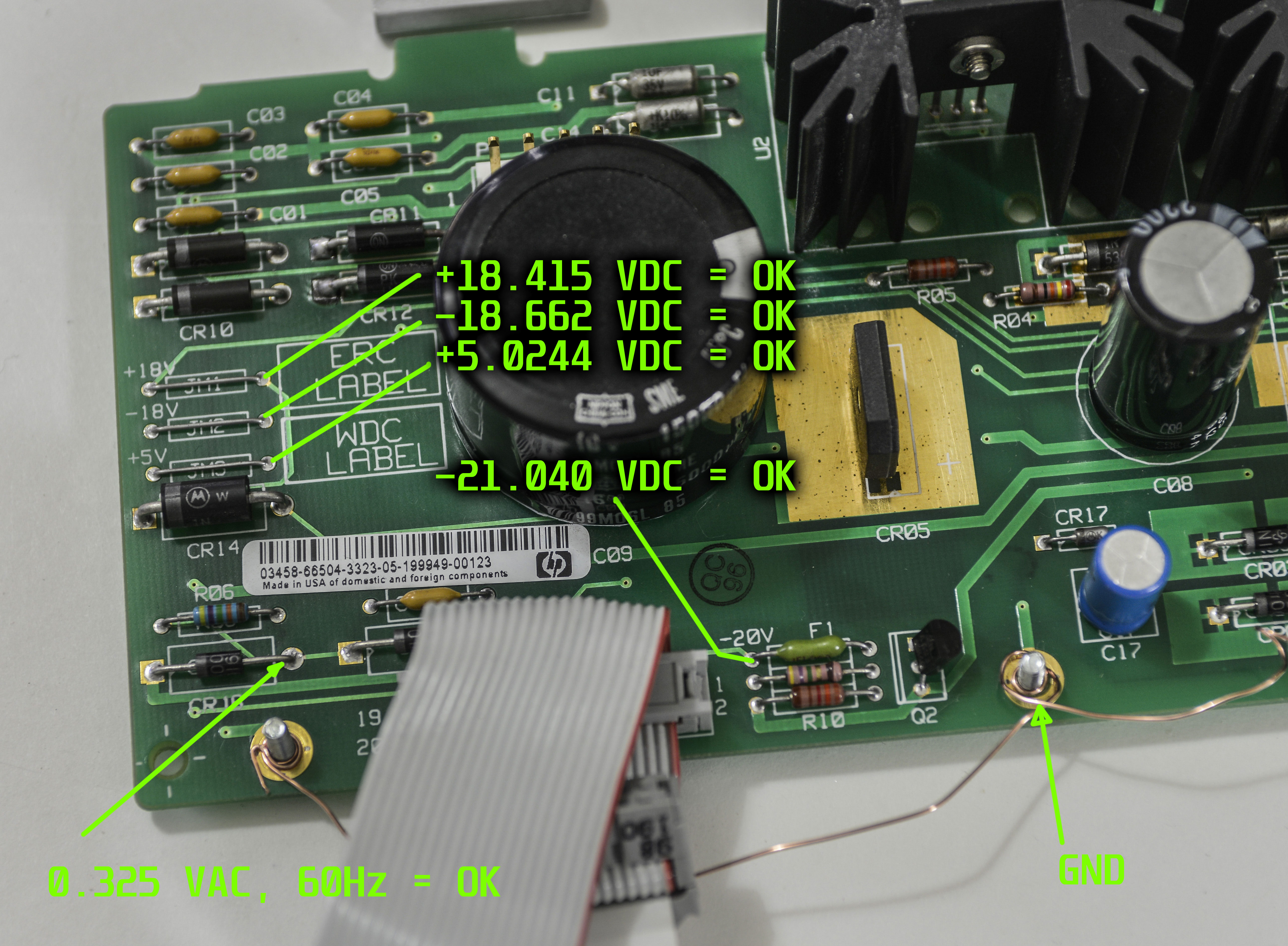
Image 66: Measured voltage outputs with Keithley transformer
There are nice labels near test points, telling us voltage test points location.
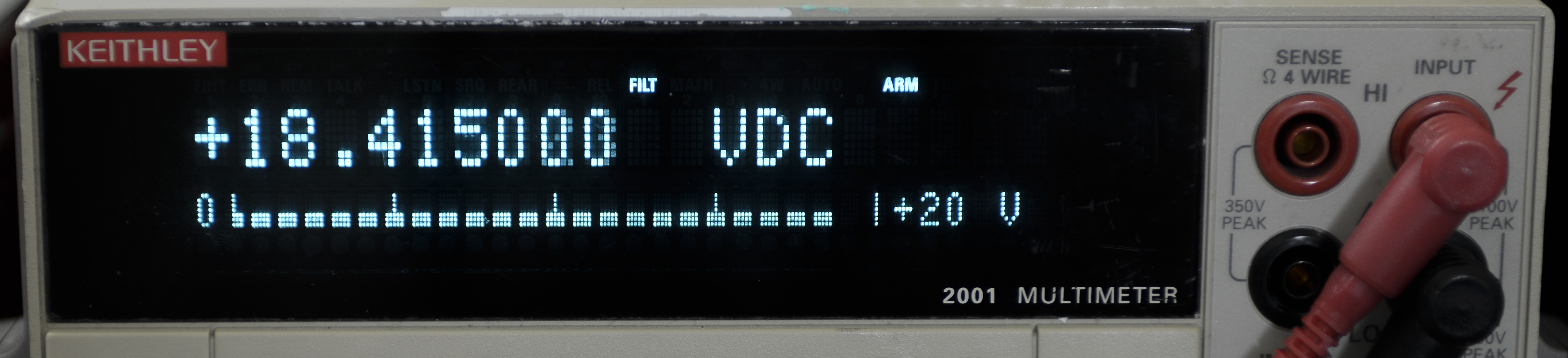
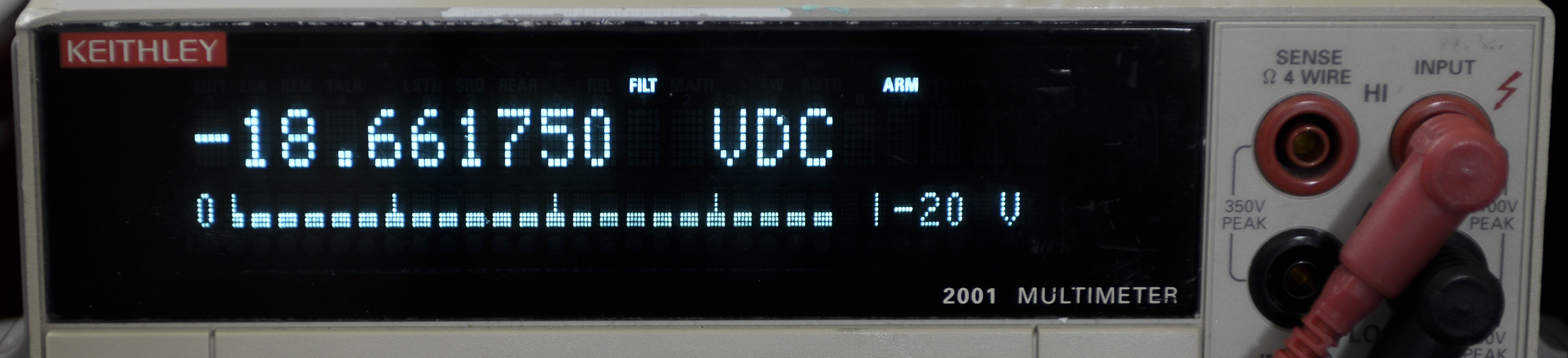
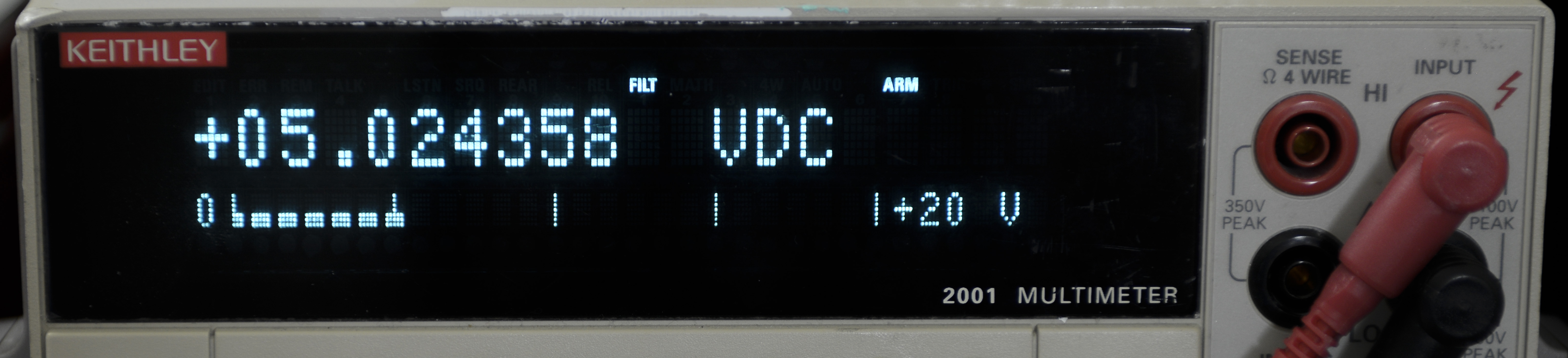
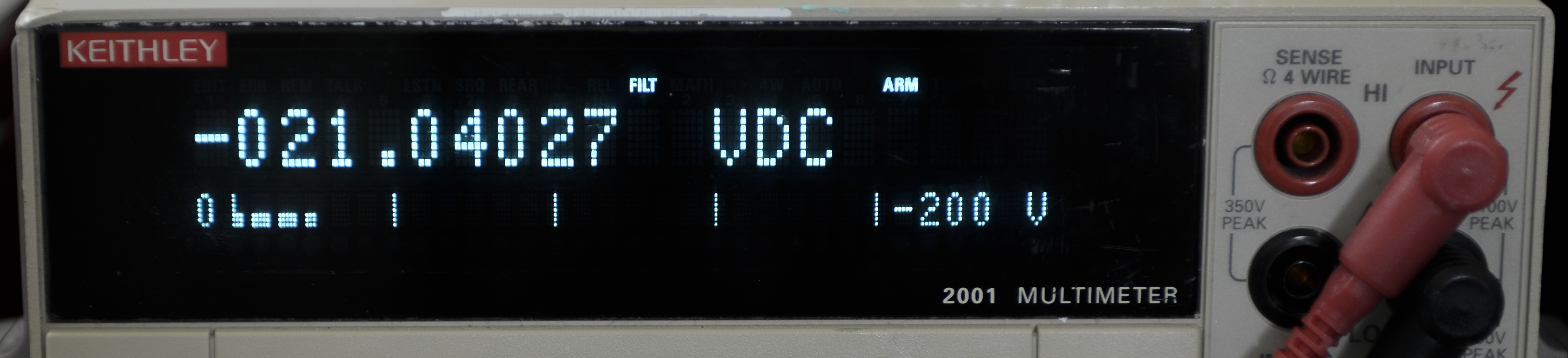
Image 67-70: Keithley 2001 readouts
All voltages are OK, also 0.325VAC 60Hz signal to read mains frequency is OK too.
I also replaced 2200MFD 35V and 15000MFD 16V electrolytic capacitors to 2200MFD 35V & 27000MFD 35V (did not find stock of 15000MFD in proper size).
Repair of A4 Inguard power supply now complete.
A1 DC Board

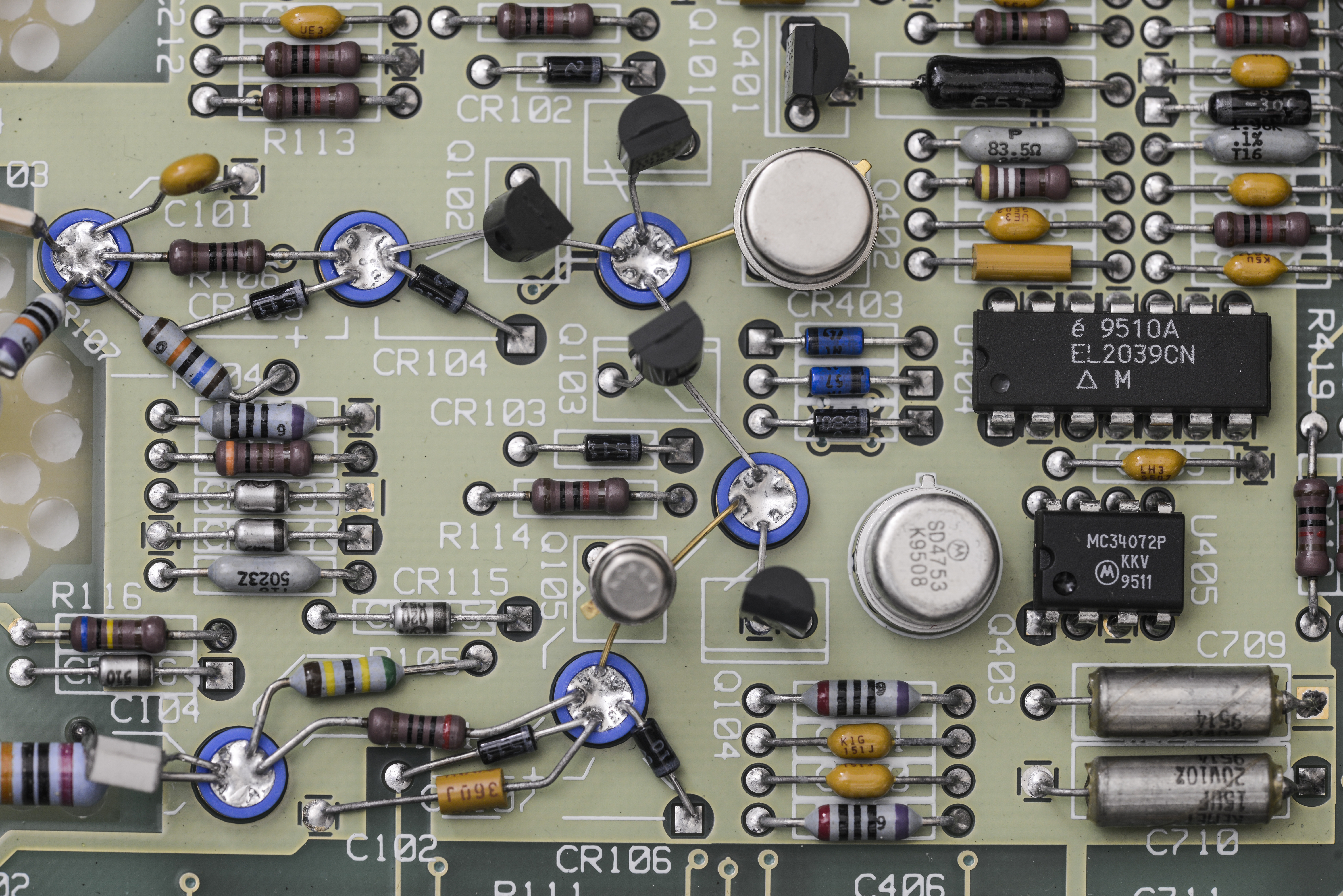
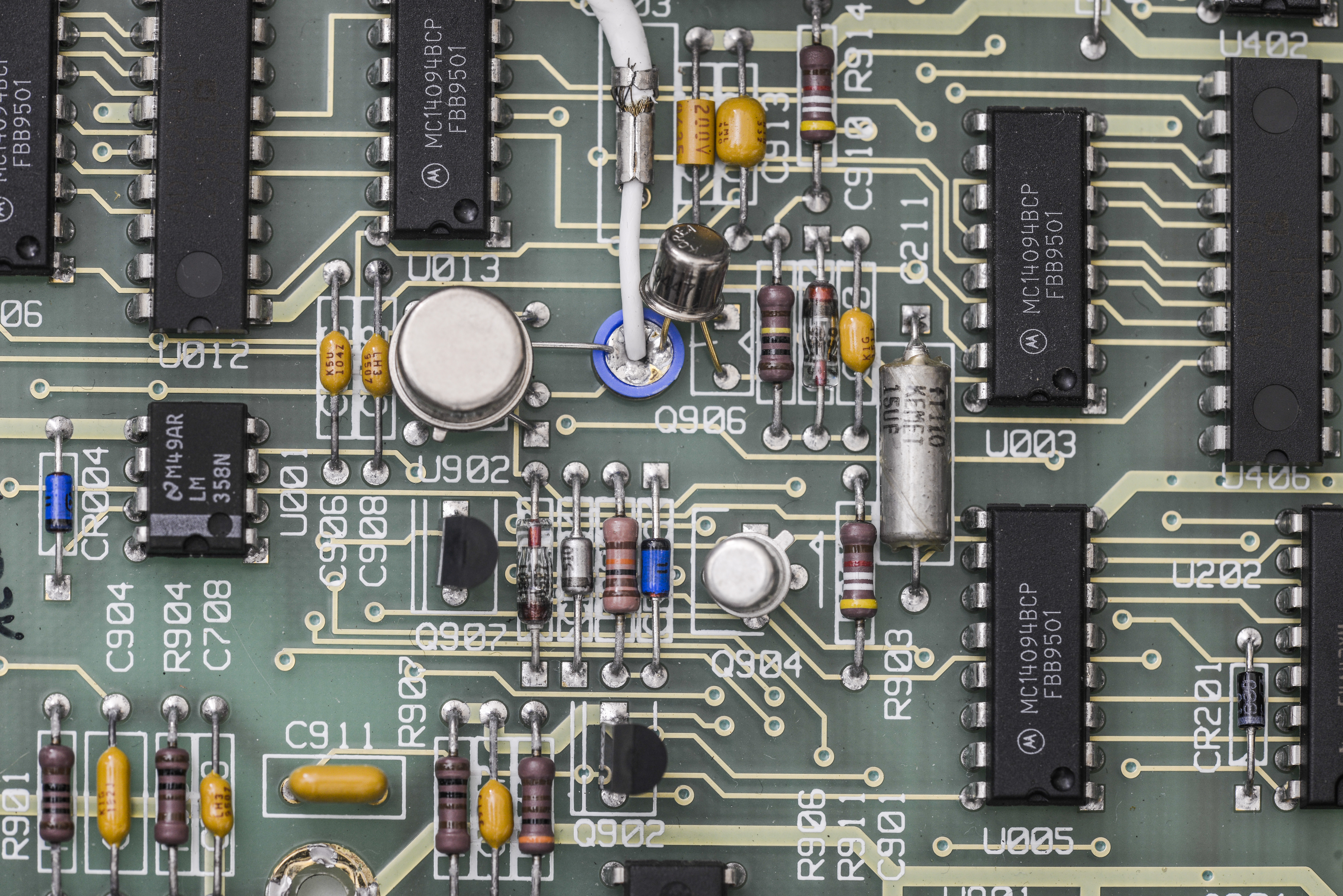
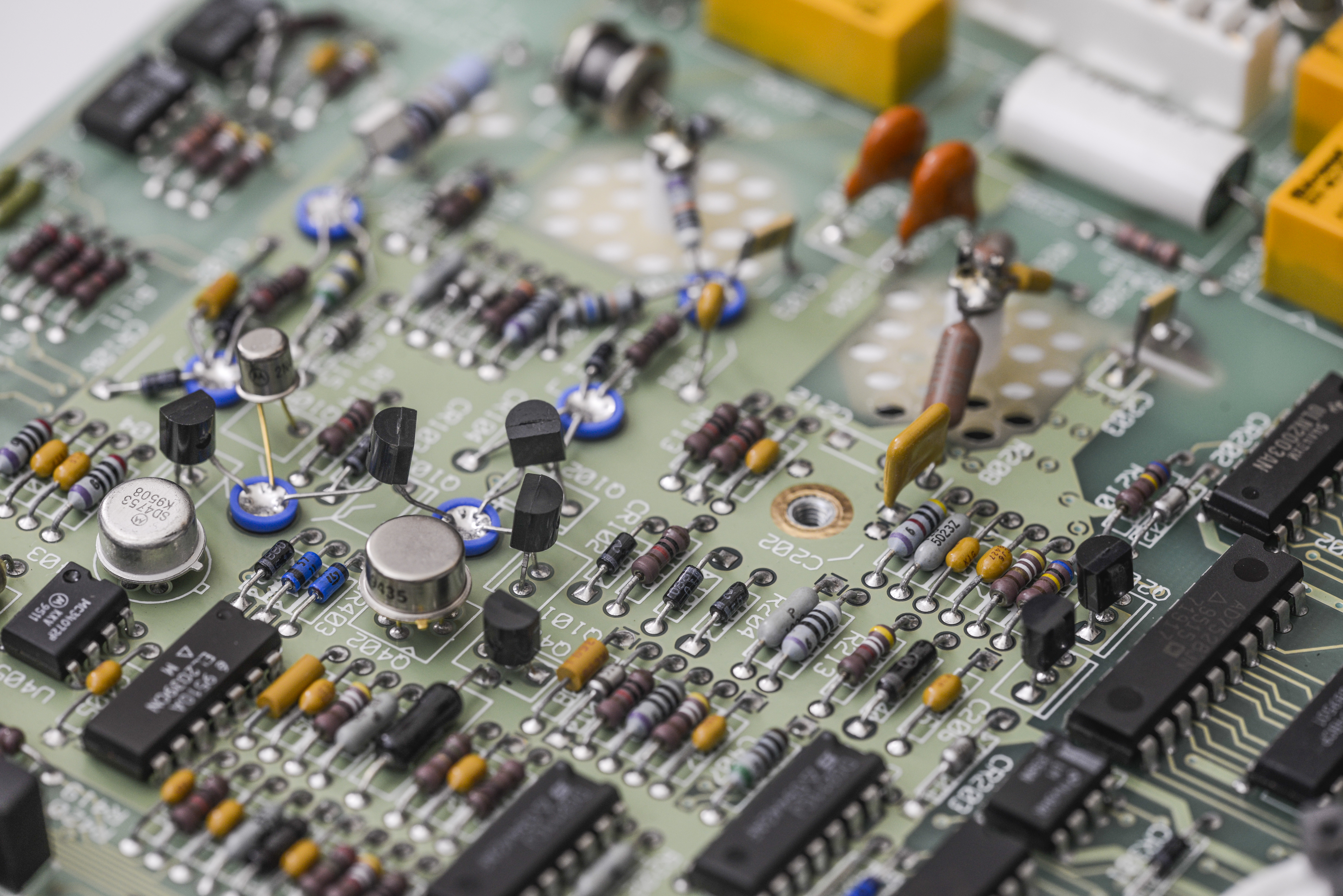
Image 71: DC main front end board, very high resolution
EEVBlog member Dr.Frank gave great analysis of input switching and relay operation. With his permission it’s included also below:
Bright red high-performance COTO reed relays can be found in bottom left side of the A1 assembly. These handle input terminals switching and range function selection. HP had COTO to make these relays custom for 3458A specific features and performance, but this reed family still exists in COTO lineup, with different part numbers, such as Series 3500.
In the 3458A’s BOM, K1 and K3 are designated as 1µV relays, K4 is a 5µV relay, so the are very low thermal EMF relays. Such performance comes at price though, they have about 200V switching/breaking voltage rating only, if we compare the actual COTO 3500 family datasheet, such as 3501. Therefore, large K7 relay is likely capable to switching >1000V, and used together to protect K1. It’s PN COTO 5000-0124, a custom part, designed for this HP meter. Actual model series may be COTO 5503, which has 3500V switching capability, and its case looks similar, see the datasheet
So K7 is used to protect switching of K1, and for the 100V/1000V range over K4.
With closer look at the switching of the low thermal EMF relays K1, K3 and K4, it’s possible these are nominal 12V types, with turn on voltage level at 9V already. All three are switched on by Q1/CR1 with about 10V, but CR7 provides another ~4.5V hold level. This dual level provides power reduction (to 25%) to further reduce self-heating of relay coil and reduce thermal EMF generation over contacts.
K1 and K7 have another special application in HP 3458A circuitry, to protect the Low Voltage DC Input very quickly. (Also the other multiplexer- inputs in different DMM modes)
Both relays were controlled by dual FF U22, and under normal conditions controlled by the CPU. In case of over-voltage event on DCV inputs, over resistor network R17/R19 in case of input voltage >±14V, U10A will quickly HW-reset K1 and K7 relays.
R17 and R19 are 10KΩ in total only, so 1000V overvoltage gives 100W of power, which must be switched off as quick as possible, within milliseconds before actual damage and overheating occur. Other DMMs, such as 34401A/34410A/34411A have 8 × 13KΩ 1W resistors instead, which makes it 10W in total only, under full overload conditions, which may be applied nearly indefinitely.
The 3458A needs this lower input resistance to meet it’s specifications of very fast DCV input path.
Also in resistance measurement function meter source test current, so current source have separate protection circuit:
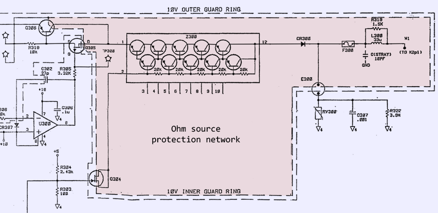
It’s protected from both voltage and current overloads. The voltage overload protected via large value resistor, which is possible due to high input impedance. Current overload protection done by a series fuse F300, diode CR300 and hybrid module Z300 on alumina substrate, which is essentially a high-voltage current limiter formed by array of 10 PNP transistors in TO92.
For positive voltage overload, CR300 is reverse biased, and virtually no current flow thru the circuit. For negative voltage overload event, power will be clamped and evenly distributed among transistors on Z300 hybrid assembly.
Additional protection is also implemented thru E300 GDT, RV300 varistor and R322 resistor.

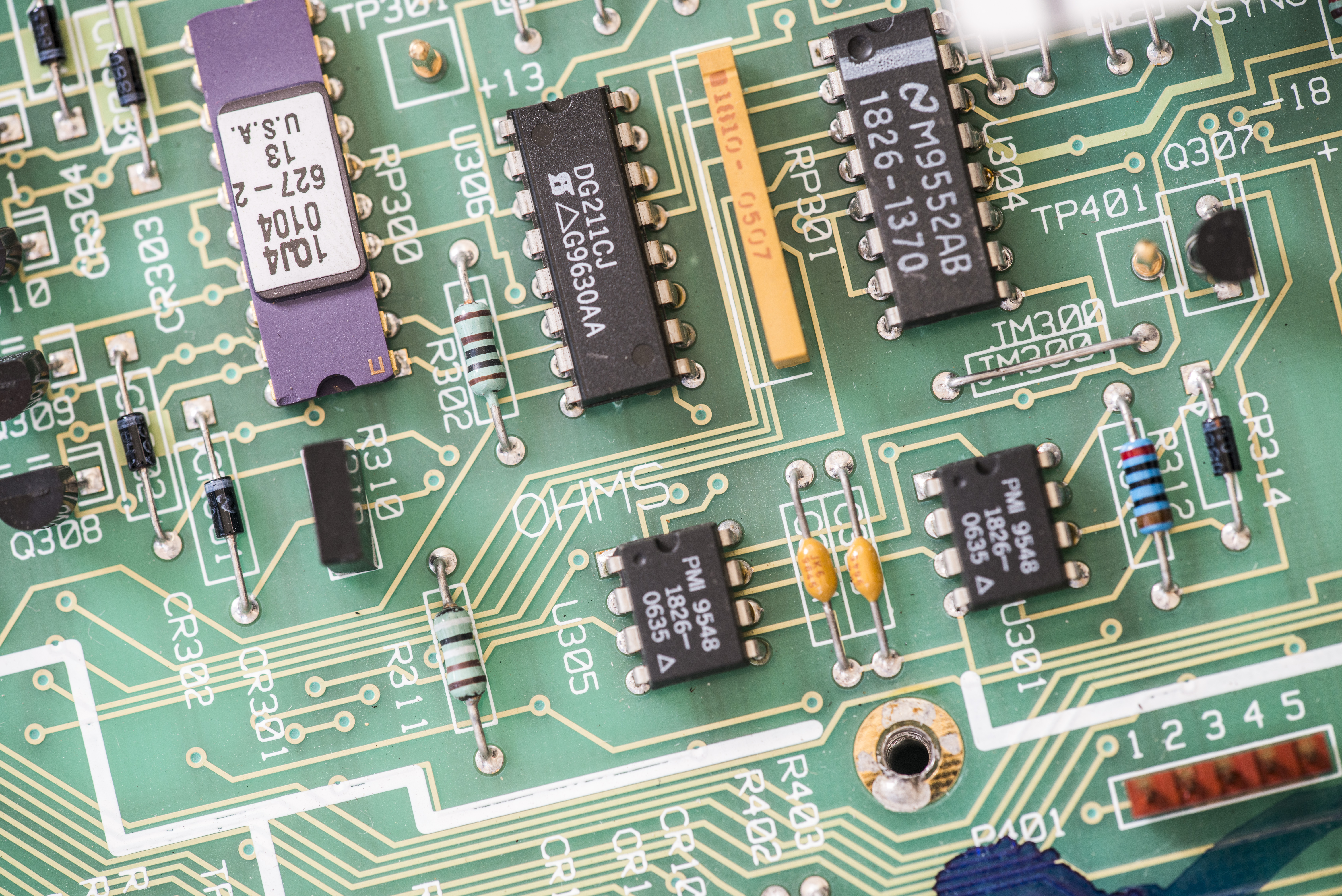
Image 72: DC main front end board, very high resolution
This board also have mark “X” around reference header, also paper tape sticker “X” in center of board near RP7 resistor network. Visual inspection shows ugly soldering and flux around parts U300, U305, U301, RP300, U304, U306, RP301, U303, RP302, RP303, R308, R307, R310, RP200 and around all relays (K1, K2, K3, K4, K5, K6, K7, K9, K200, K201, K202, K203, and K204). Relays have date codes from 1997, while rest of the board IC’s dated 1995-1996. Previous owner tried to fix board by replacing relays?
Image 73: Solder blobs and flux residue from previous owner repair attempts
Looking not good, if you ask me. That’s why even broken gear sold by inexperienced owner, without attempts of non-qualified repair is easier to restore than hardware which looks mint externally, but have solder bodges and flux all over the field inside. Oh well, let’s continue.
A2 AC/TRMS board
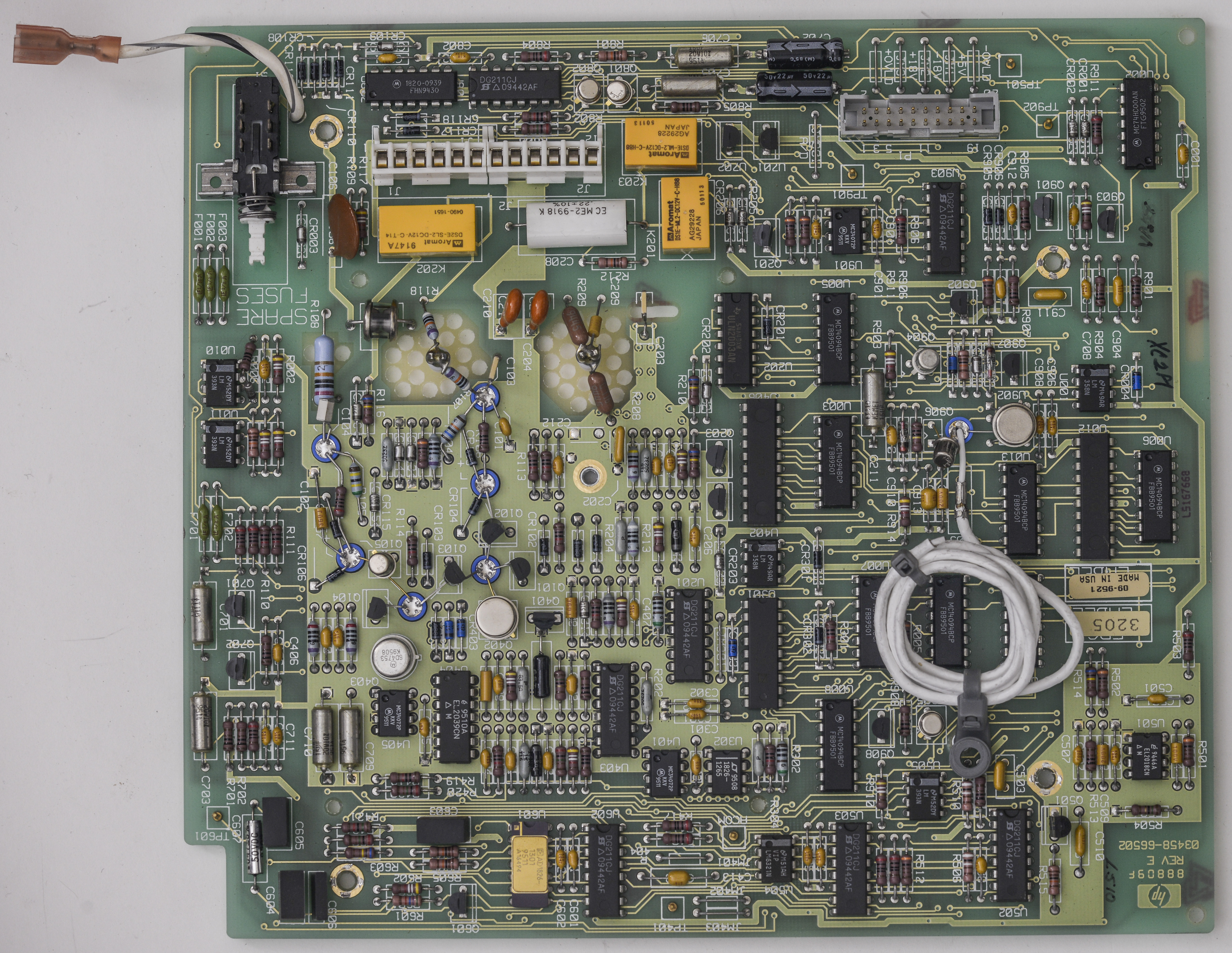
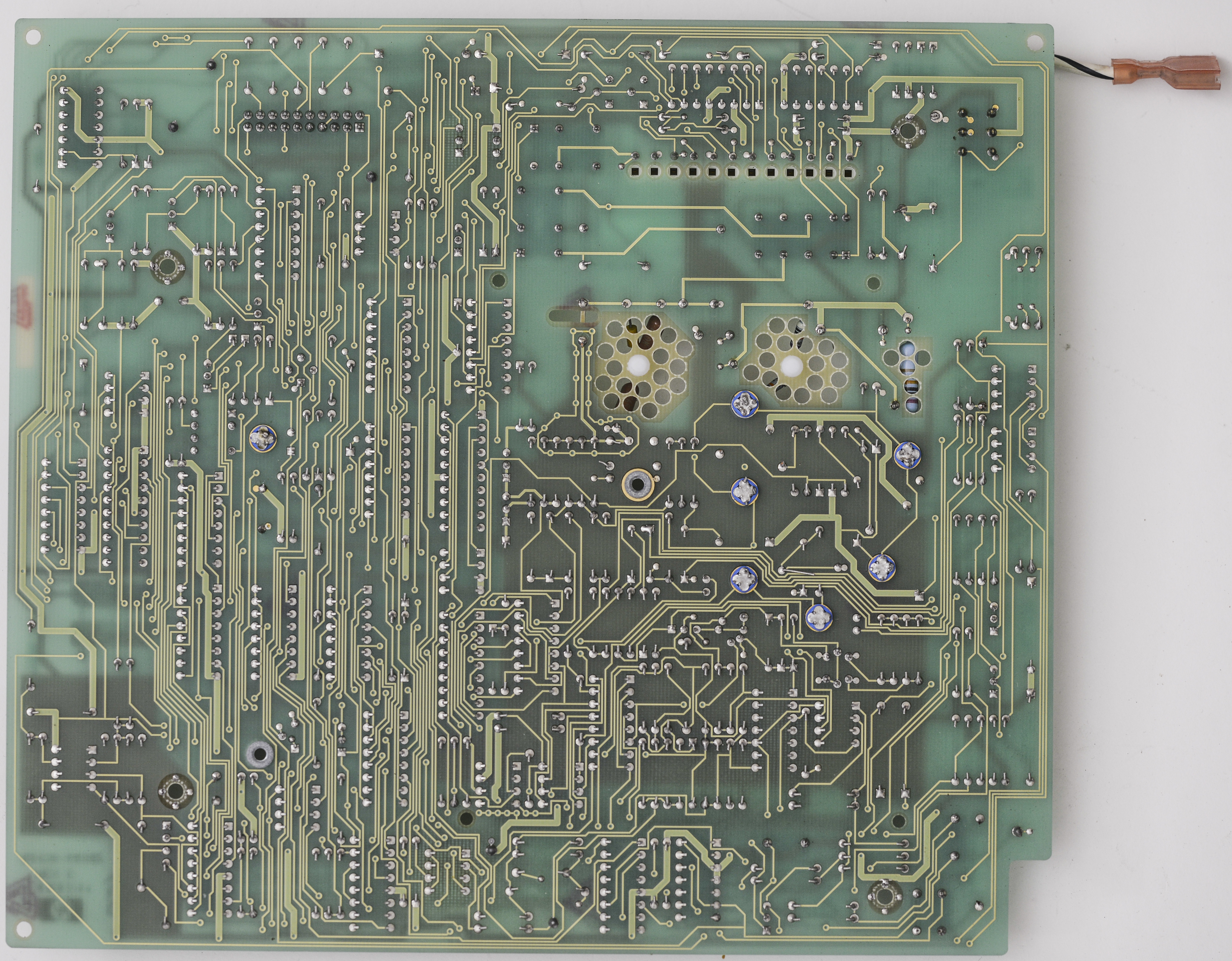
Image 74-75: A2 board 03458-66502, top and bottom side
My board have ERC (Engineering Revision Code) over 3108, so modification covered in Service note 3458-06A : Modification to Fix Hardware Error, “ac offset DAC 10mV invalid cal value: 184” is not required.

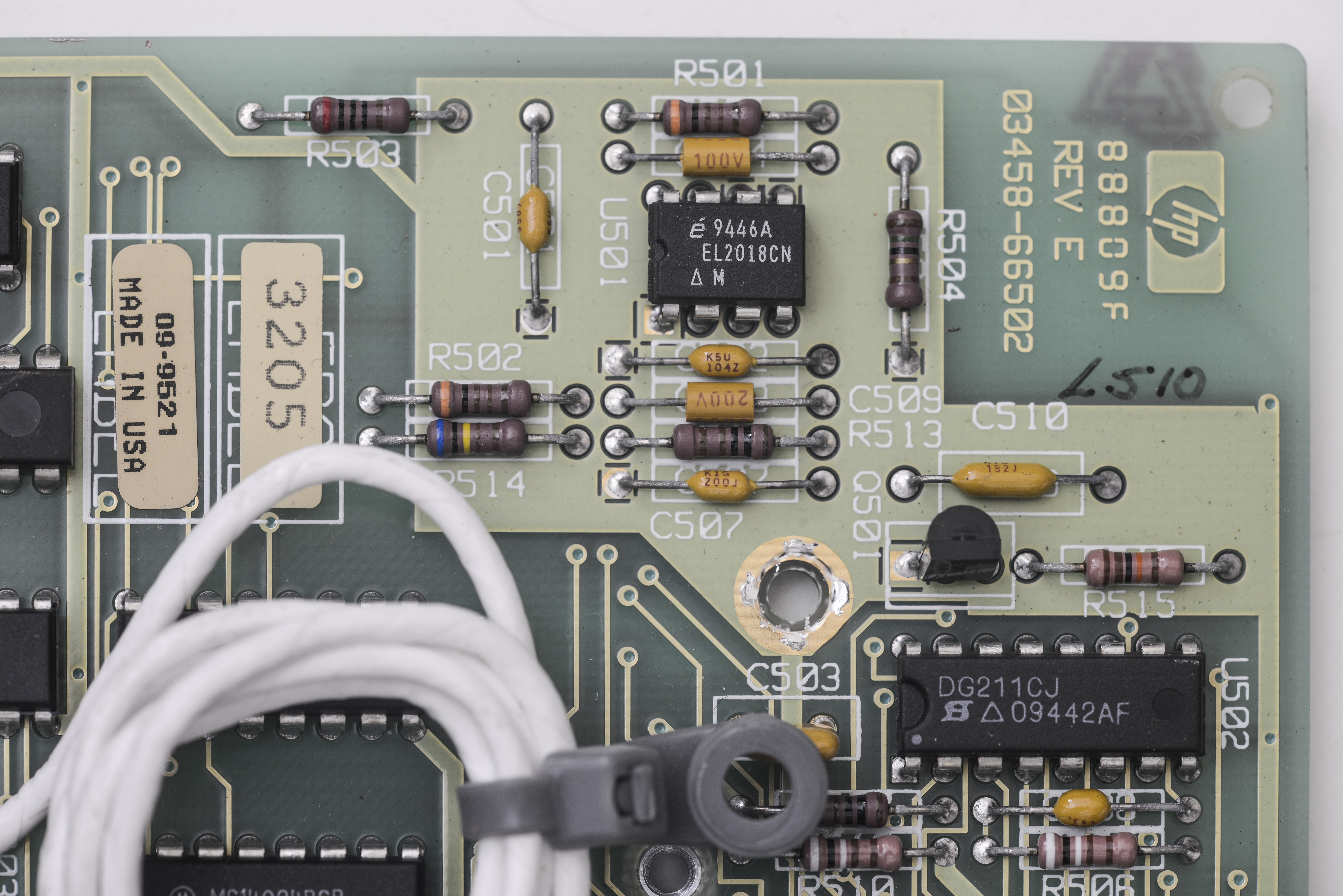

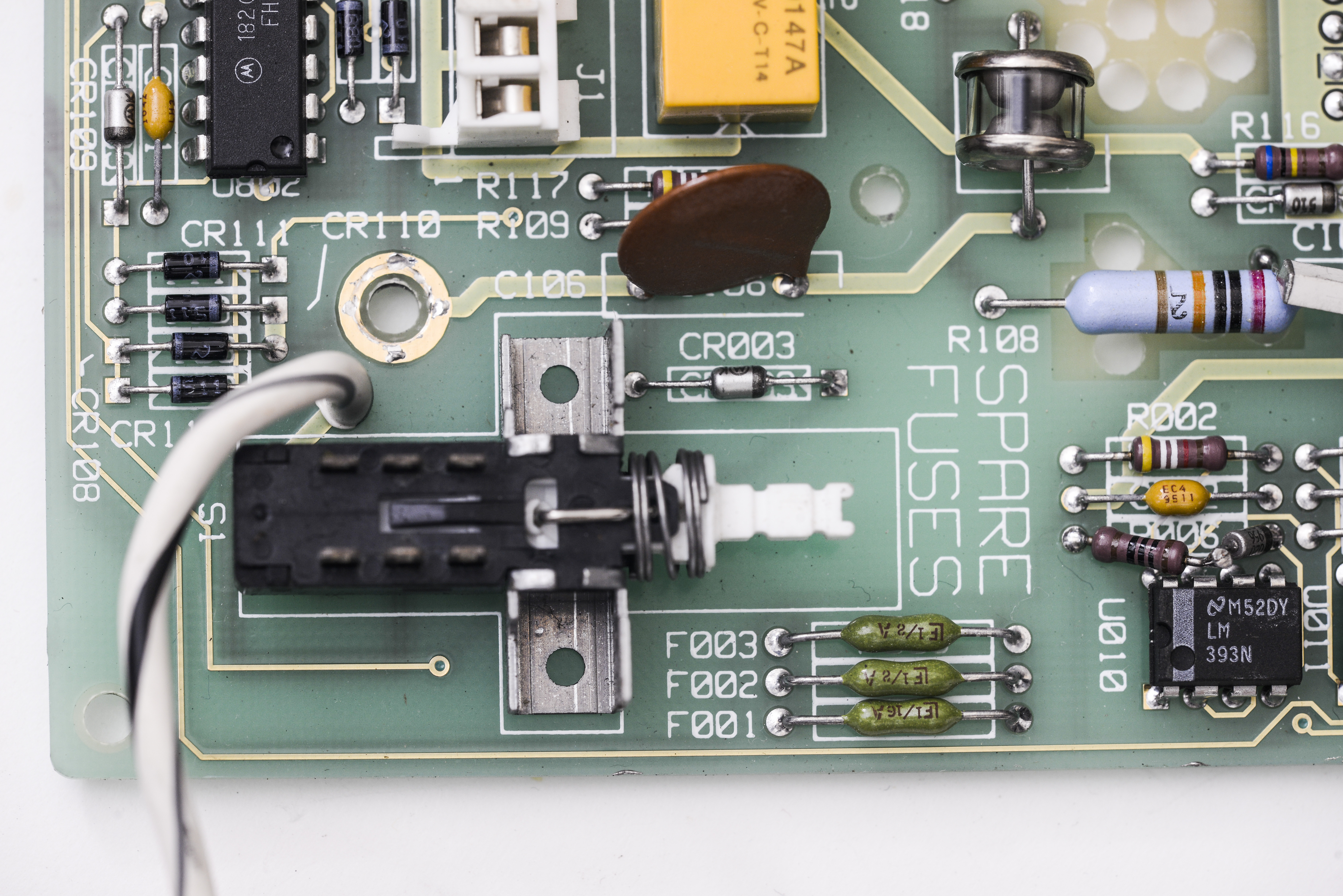
Image 76-79: A2 board condition and closeups
Teflon standoffs and “wires-in-the-air” mounting was used to avoid PCB surface leakage into sensitive nodes and signal nets.


Note interesting construction of C903 100pF capacitor. It’s spool of Teflon insulated coax, which have very good insulation and low DA, making it great choice for sample&hold circuitry.
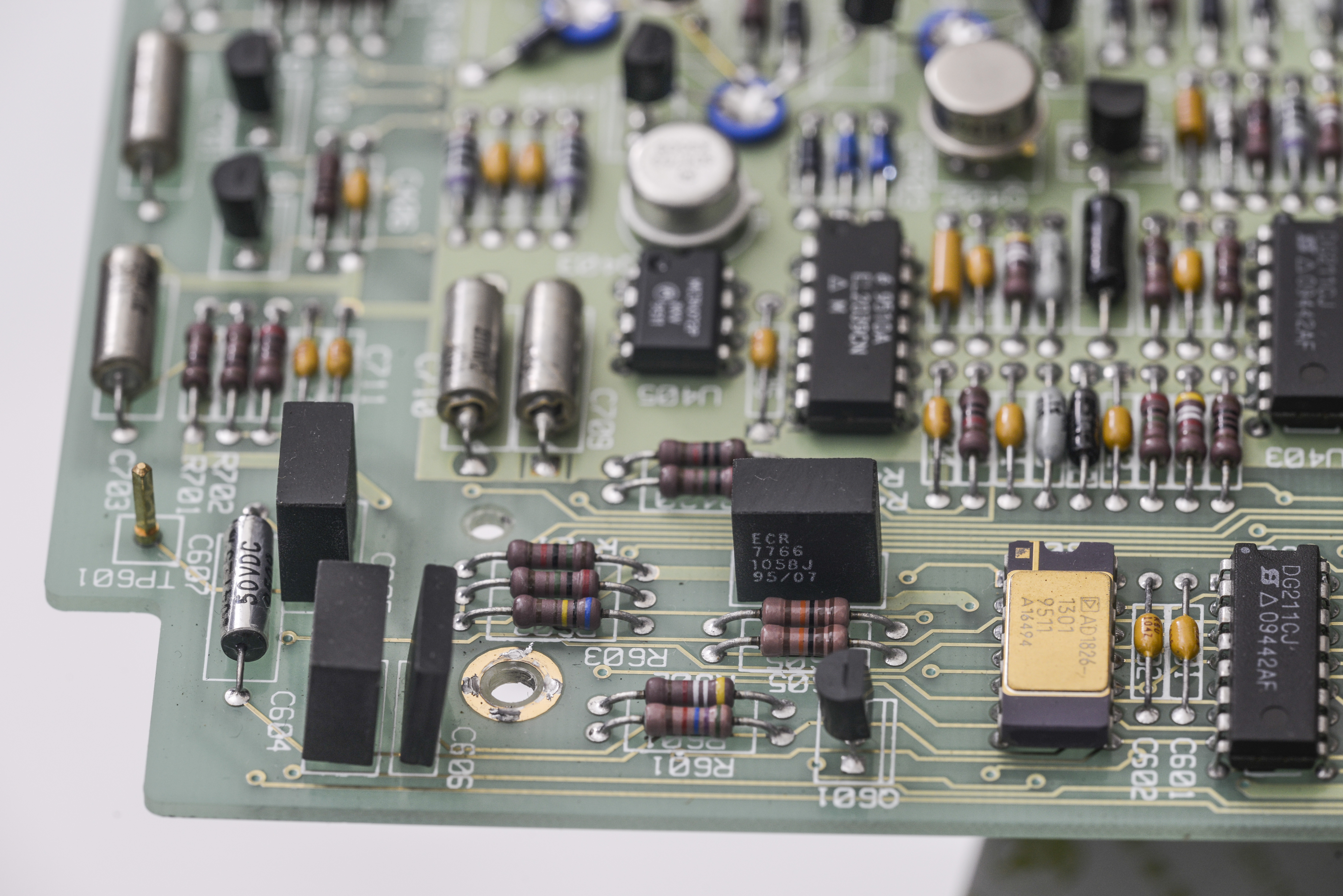
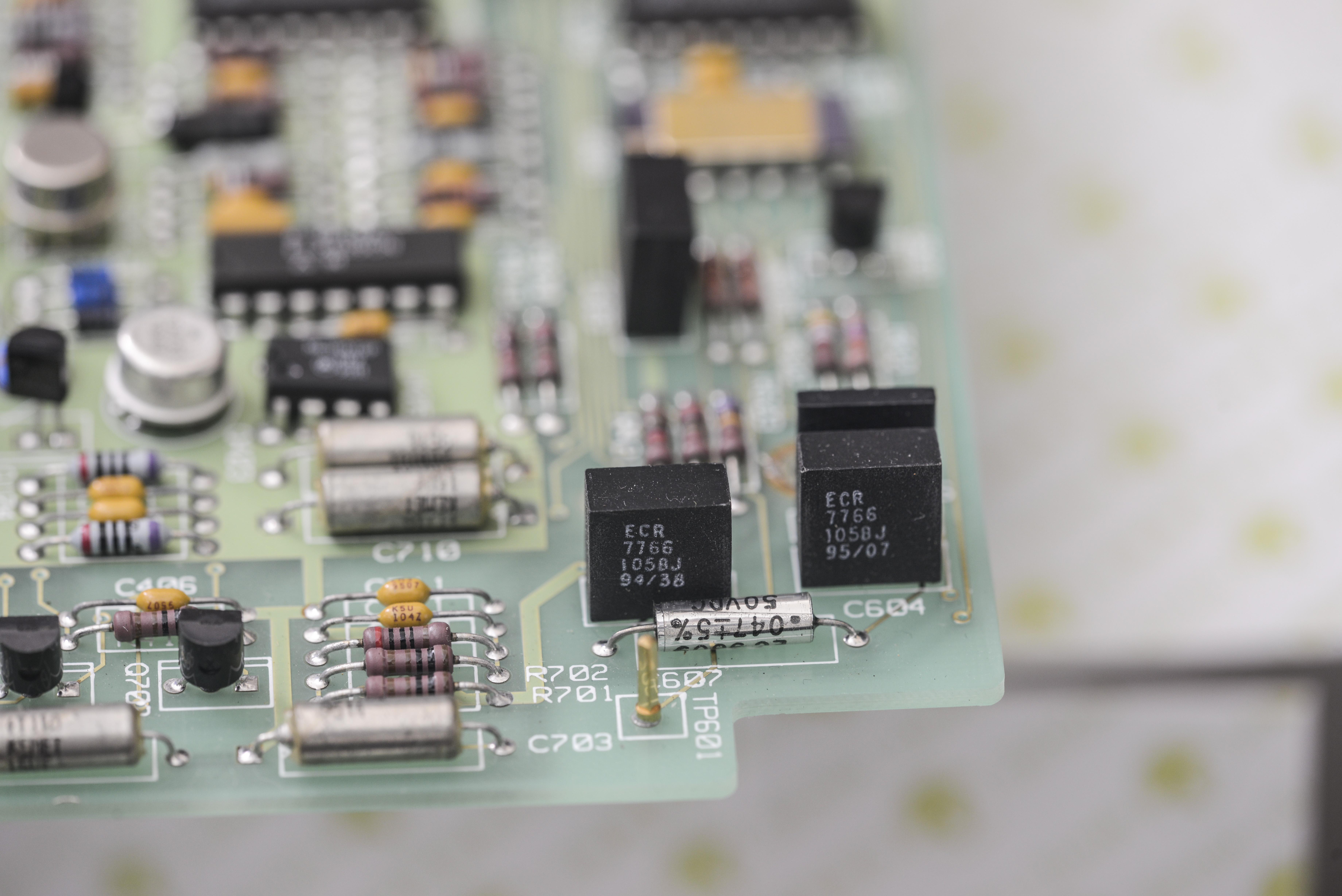
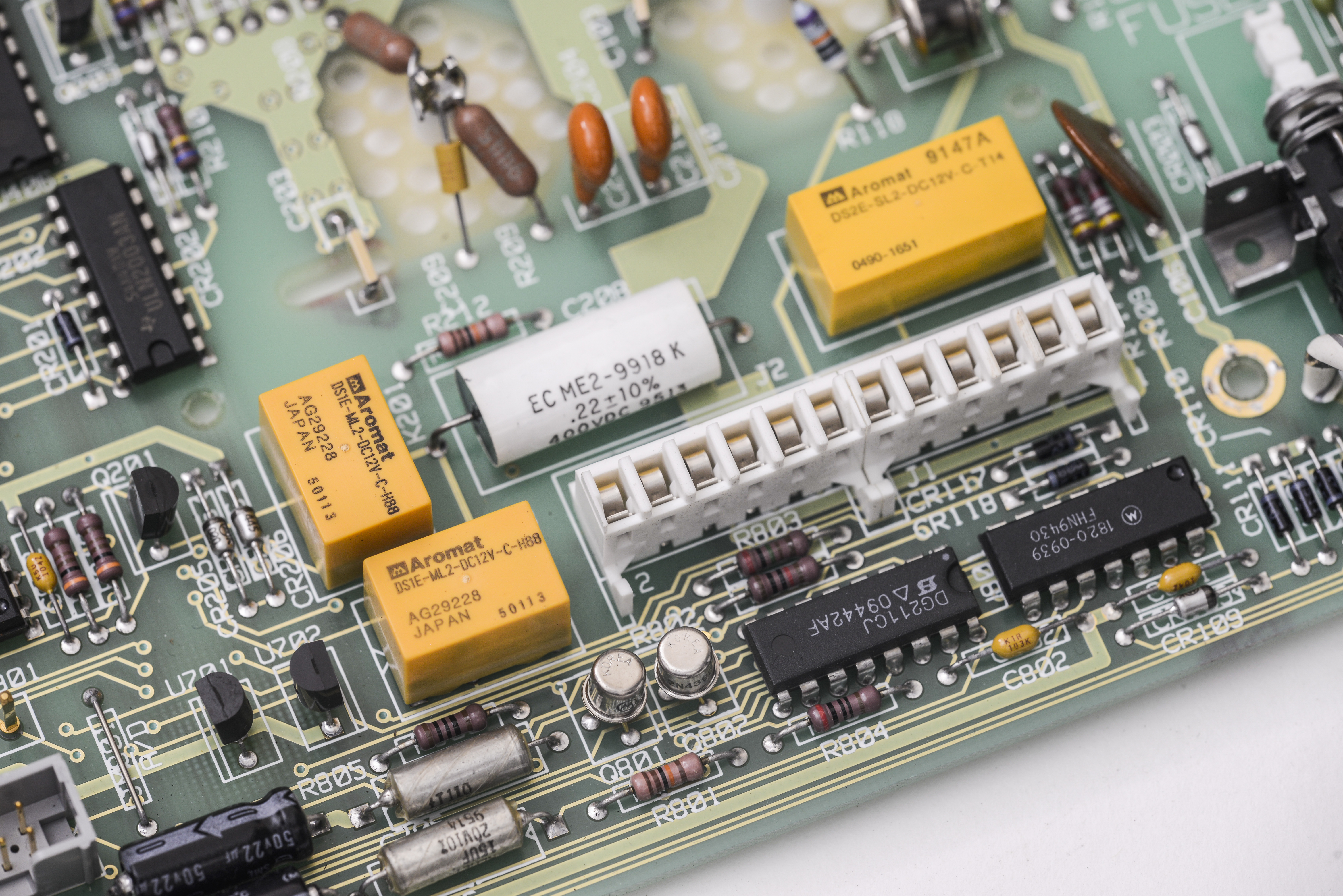
Image 80-91: High-impedance circuits of AC voltage converter
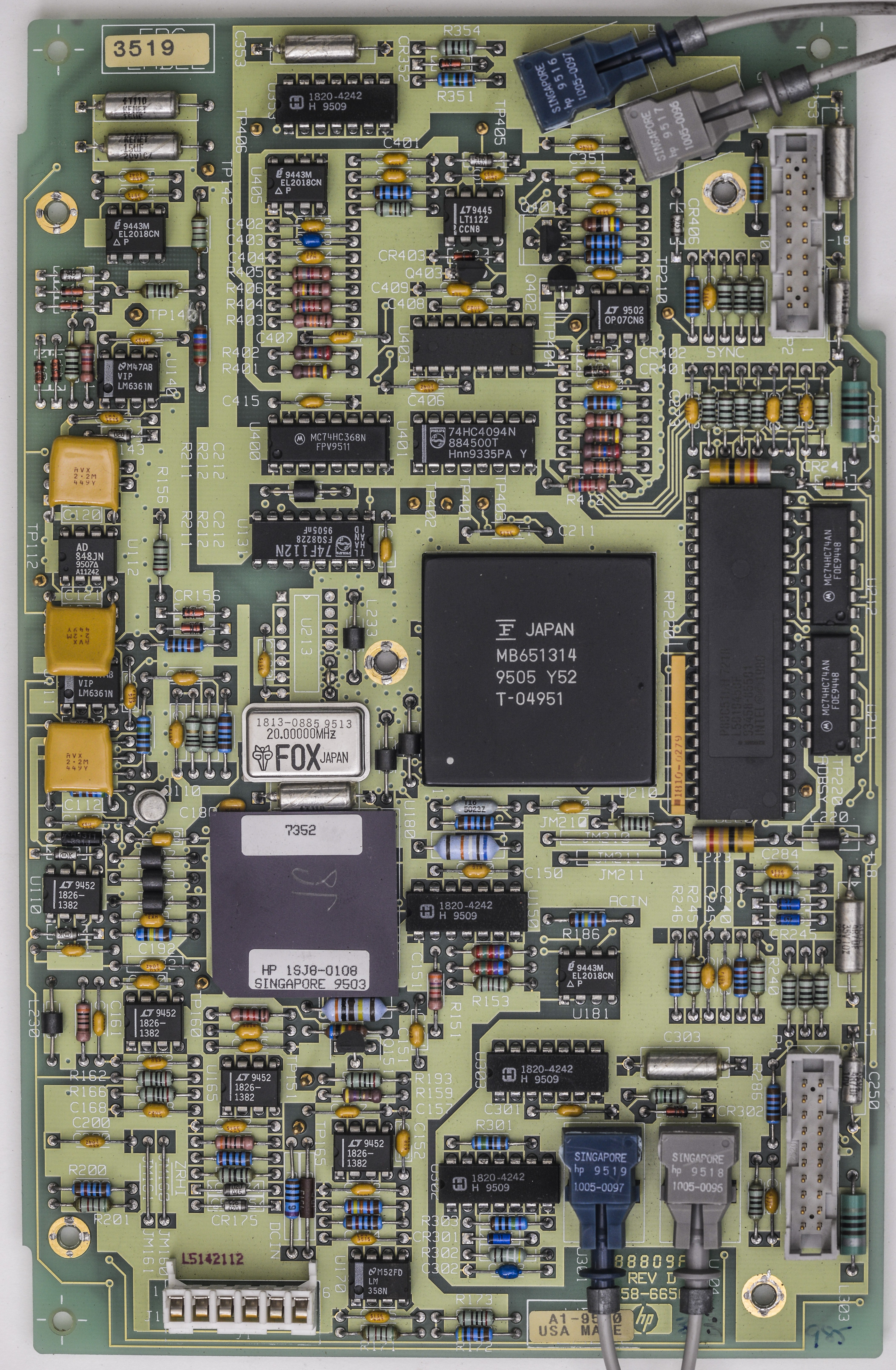
A3 ADC Board
A/D Converter board is heart of instrument popularity and performance. It’s capable of performing 16bit (corresponding to 4½-digit resolution) conversions at 100kSPS speed or full 28bit (8½-digit mode) conversion at 6SPS, with <0.1ppm linearity.
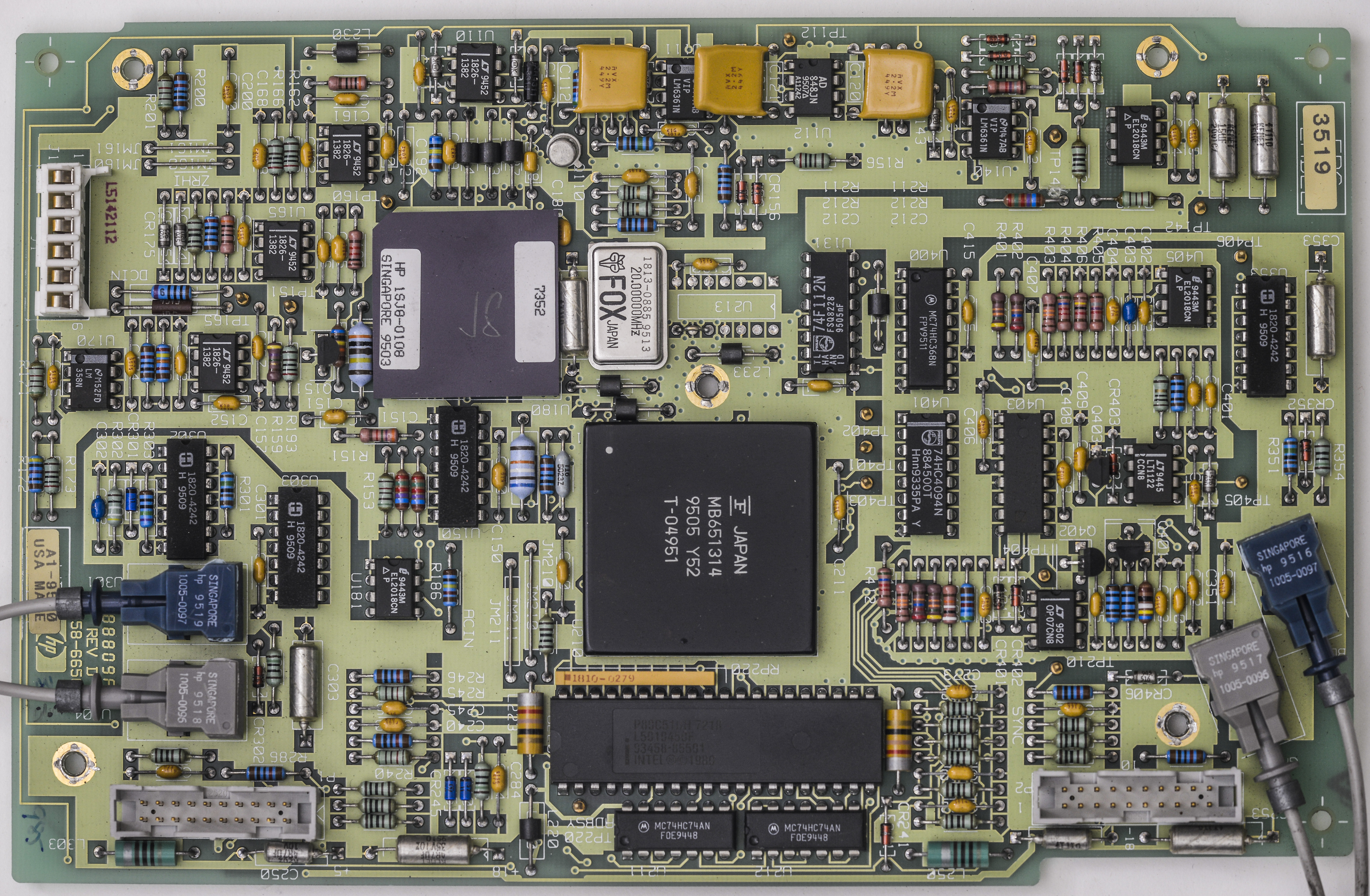
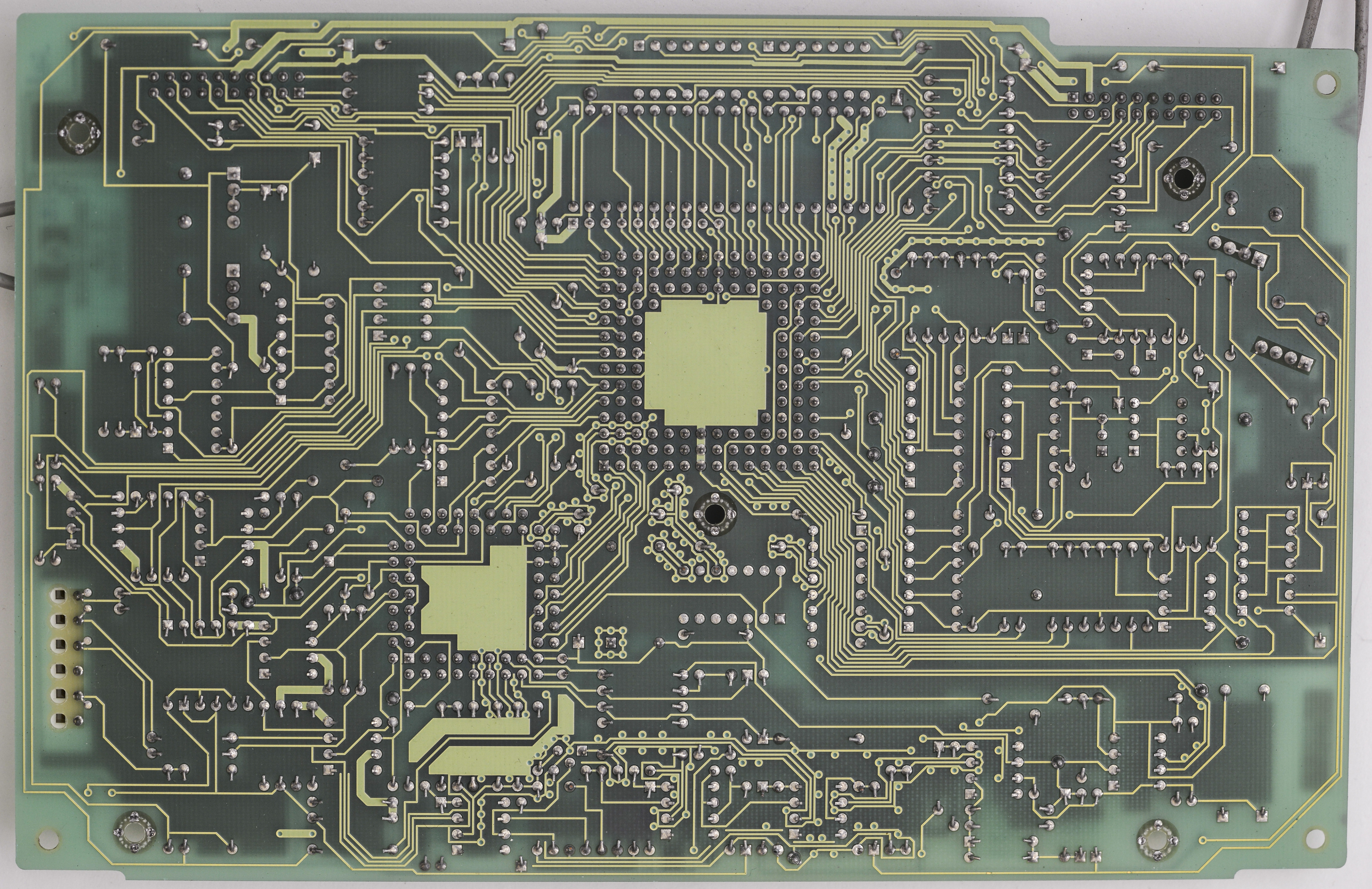
Image 92-93: HP 03458-66503 analog to digital converter, top and bottom side
Worth to note, not all 3458A’s have same A3 board. There are multiple A3 board revisions, and schematics in CLIP is for one of first revisions. There are some important differences, not reflected in this old schematics.
| A3 PCBA Version SKU | 03458-66503 Rev.A | 03458-66503 Rev.C | 03458-66503 Rev.D | 03458-66513 New | 03458-66513 New-R | |
|---|---|---|---|---|---|---|
| Board photograph |  |
 |
 |
 |
 |
|
| First released | 1988 | 1989 | ~1995 | 2000 | 2015 | |
| U180 Hybrid | Same package and footprint | |||||
| Interface MCU 8051 | Mask 03458-85501 | Rev.2 Mask , ATMEL 8051 | ||||
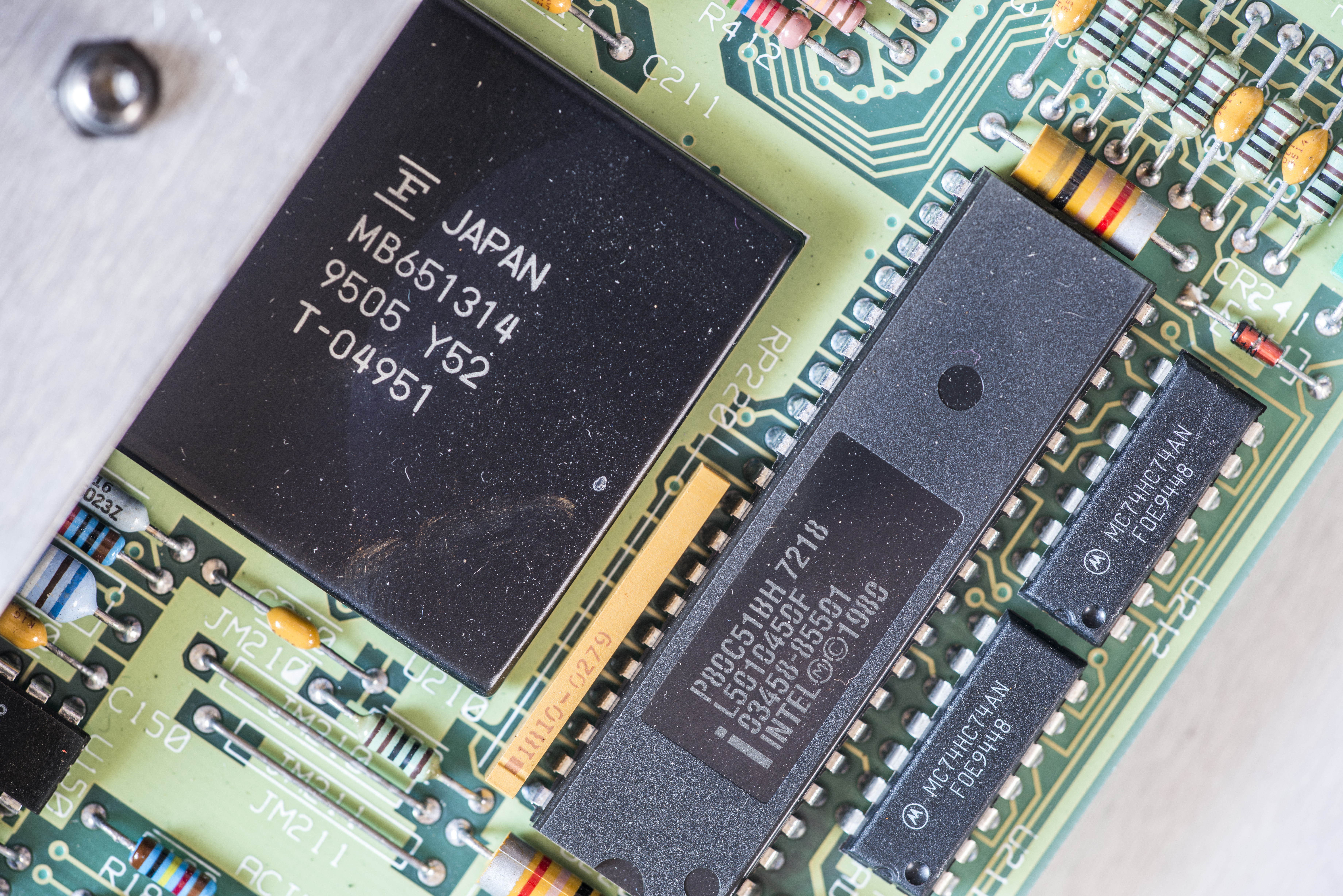
| U210 Gate array ASIC | Fujutsu MB651314 PGA | Patch PCB 03458-26550 with ALTERA CPLD | ||||
| Optical interface | HP 1005-0097/HP-1005-0096 | Avago HFBR-2521Z/Avago HFBR-1521Z | ||||
| Integrating cap | MLCC 50V | 50V black plastic NP0 | yellow coated MLCC | |||
| U213 position | 74F112PC | HP 1820-2924 IC | Jumper pin 8 – pin 10 | |||
| ADC U142/U405 comparator | EL2018CN DIP8 (HP 1826-1817) | Patch PCB 03458-66530 with EL2251CM | ||||
| U404 ramp opamp | Hermetic LF400C | Plastic LT1122 | ||||
| C401,Q402 | Hermetic metal can | Plastic | ||||
| C146,C147 capacitors | None | Present | ||||
Table 10: Different revisions of A3 PCBA
Close-ups on PCBA components

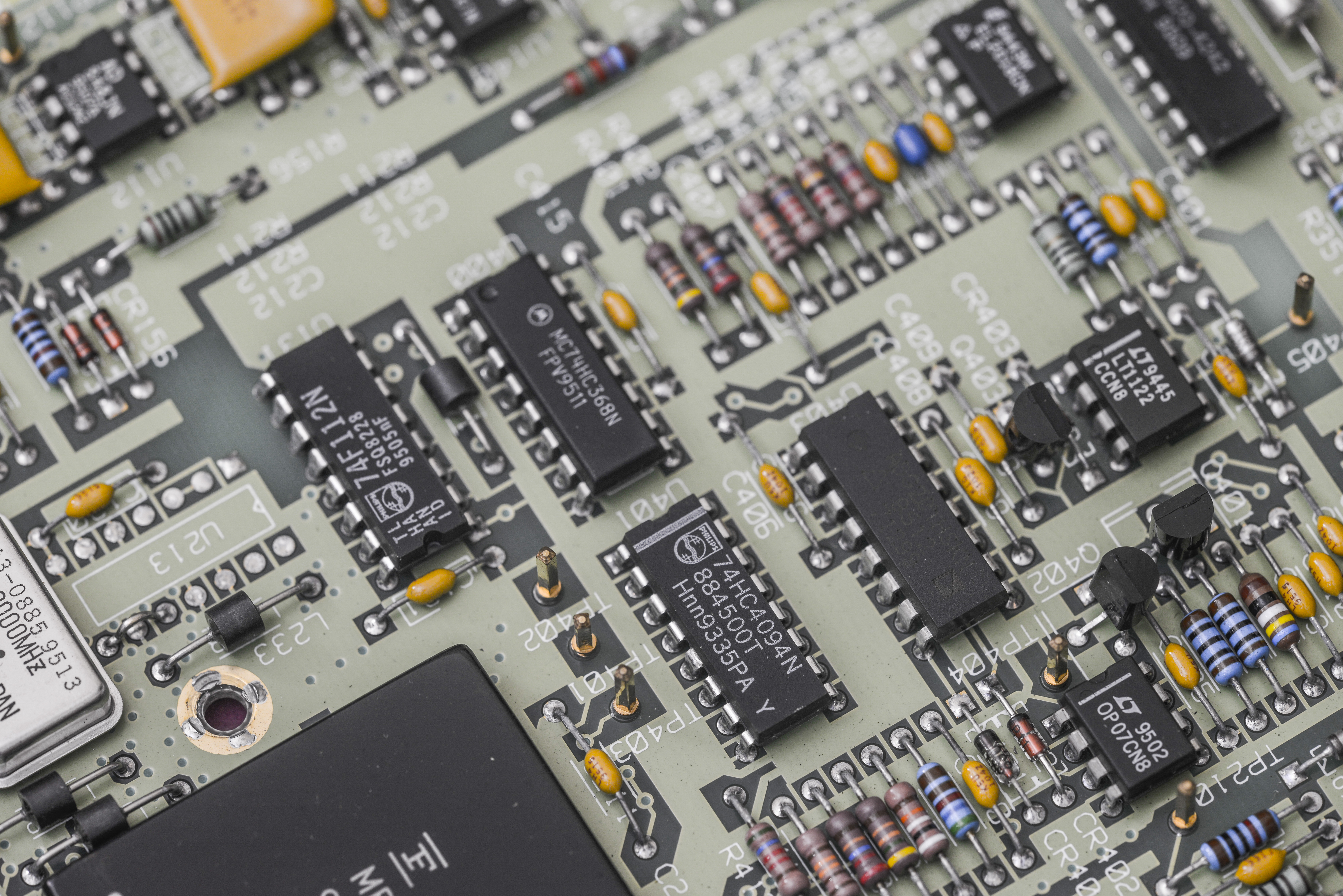

Image 94-99: A/D PCBA circuits
This board also features its own Intel 8051 microcontroller, with mask firmware 03458-85501. This MCU is orderable from Keysight.
ADC board interfaces to Outguard main processor thru 2Mbit bidirectional UART optical link, using fiber Avago’s Versatile Link cables. HP have related PDF-document covering this application as well.
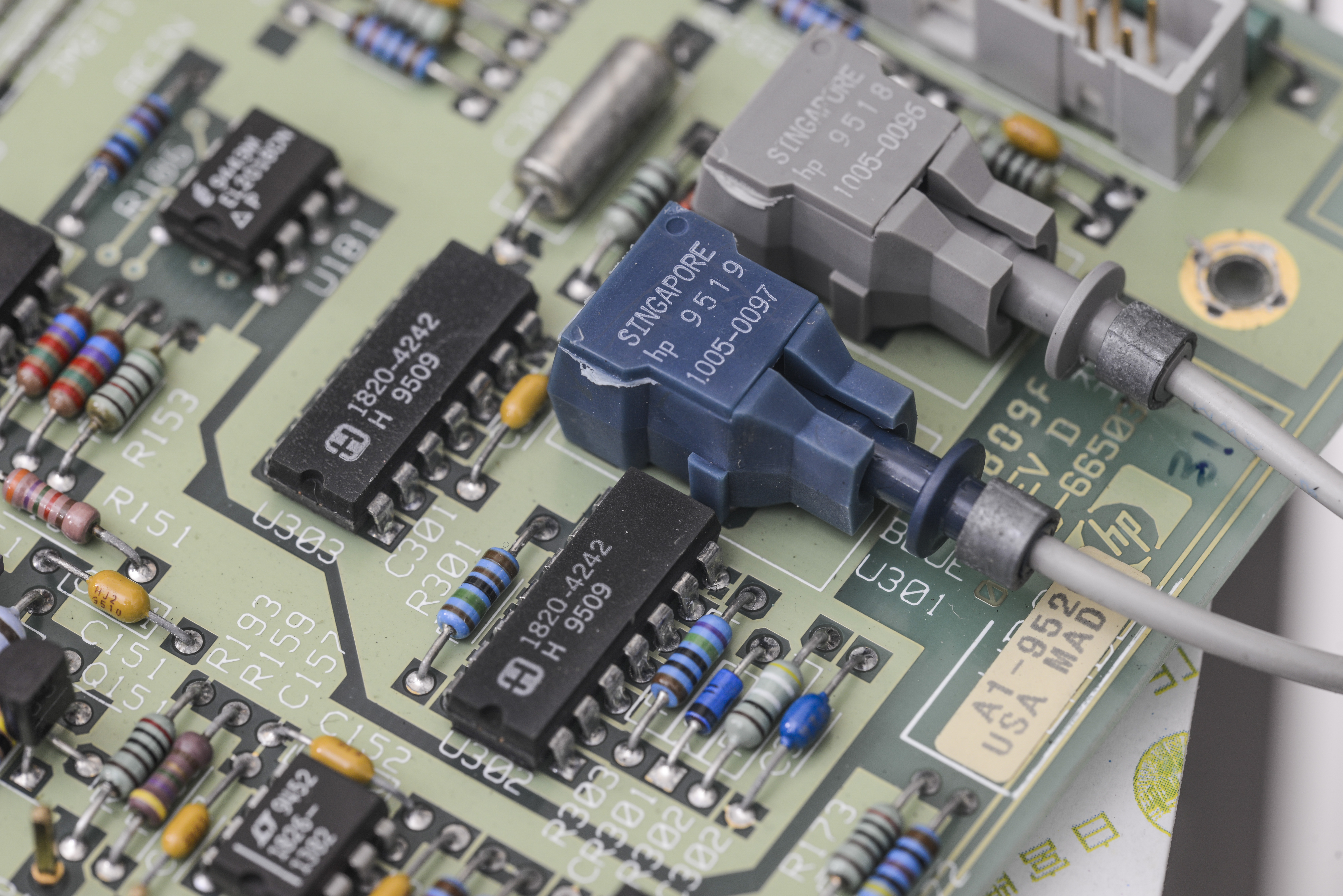
Image 100: VersaLink optical isolation interface
Since our unit have S/N later than 2823A00700 and also ERC is 3519 we don’t need modification covered in Service note 3458-01C, my board have mentioned capacitors 15uF 10VDC. There is installation manual available for A3 board replacement.
A9 DCV reference board
This board was missing, so I had to buy replacement from secondary market. It’s often possible, because famous reference board from 3458A often on sale on auctions and from precision enthusiasts. I got mine, standard variant for little over $130 USD, shipping included.
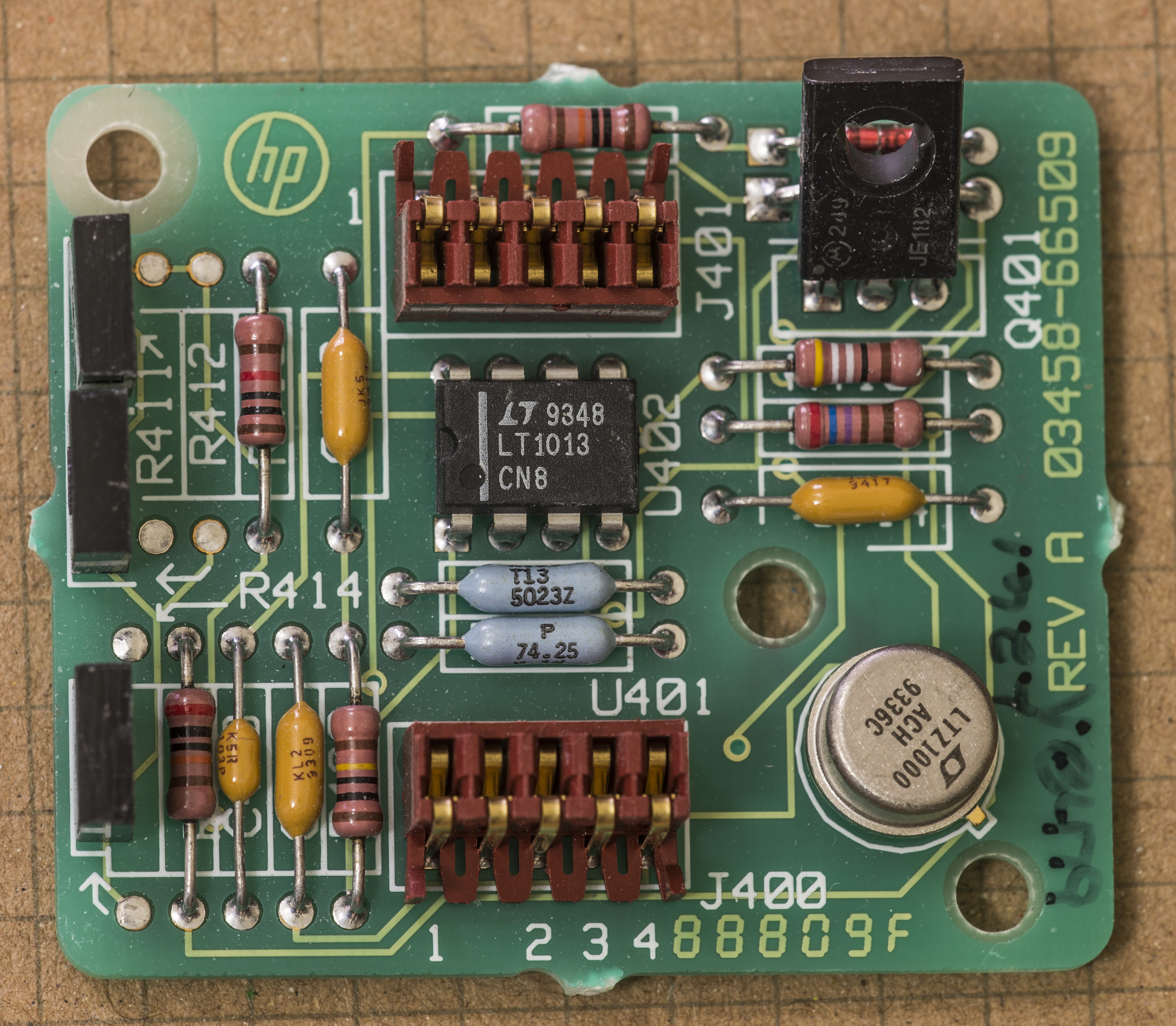
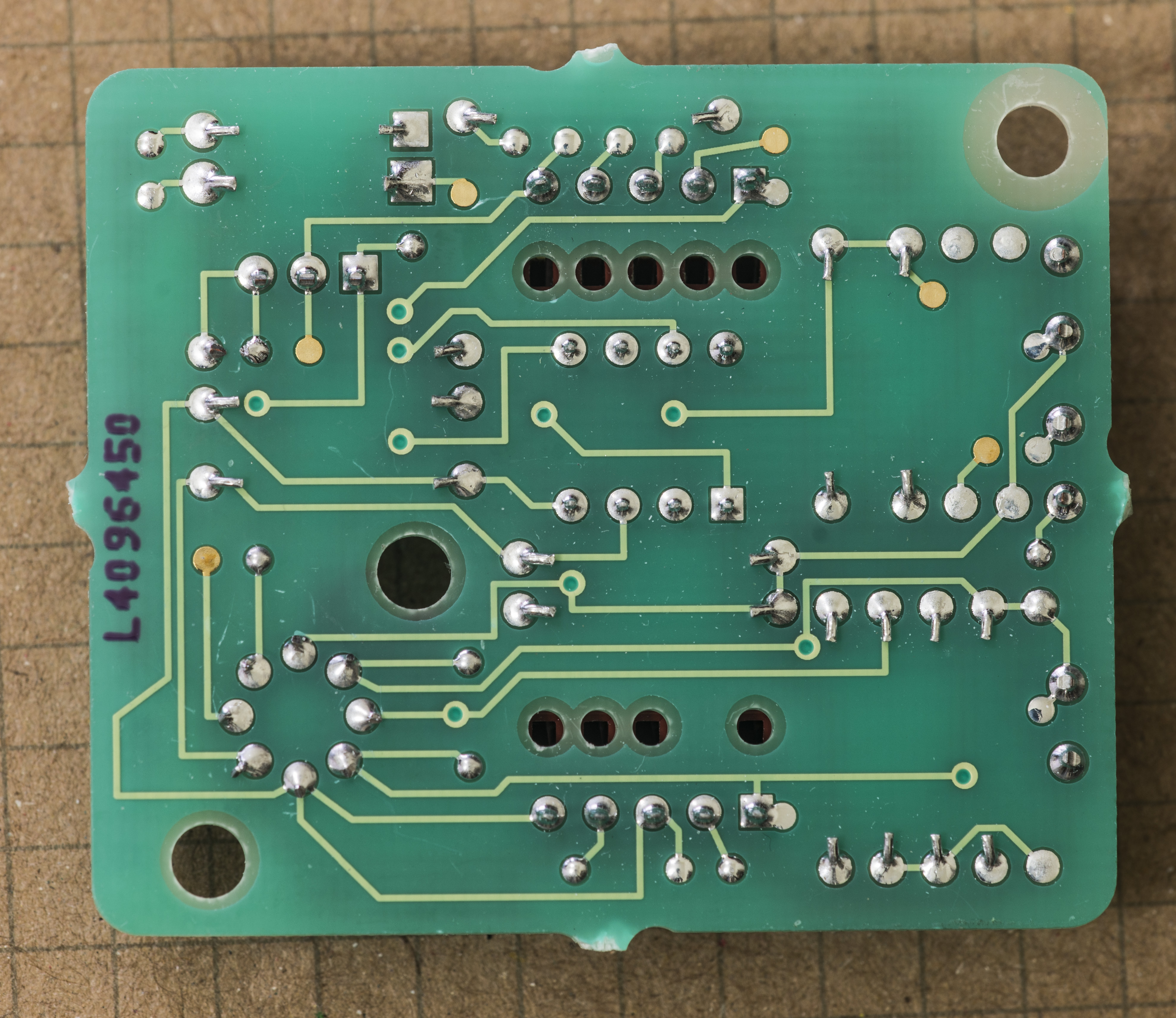
Image 101-102: HP 3458A 03458-66509 standard Linear LTZ1000 DC reference board
Little module is almost exact copy of LTZ1000A’s datasheet reference schematics from Linear.
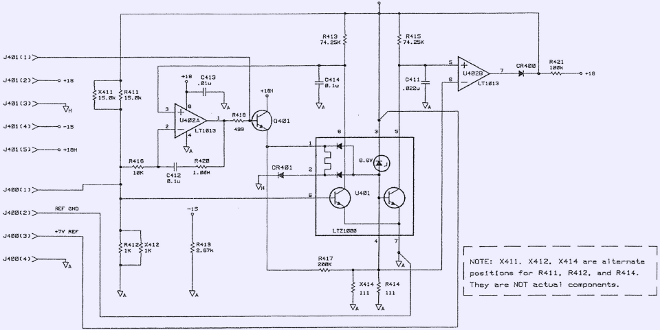
Image 103: LTZ1000 voltage reference PCBA schematics
Heart of the reference is Linear Technology LTZ1000A Super-Zener with integrated temperature sensor and oven heater. It’s most stable commercially available reference, even today, providing temperature coefficient below 0.05 ppm/K and very low noise and long-term drift rate. With proper support circuitry this chip can deliver stability less than 1 ppm per year.
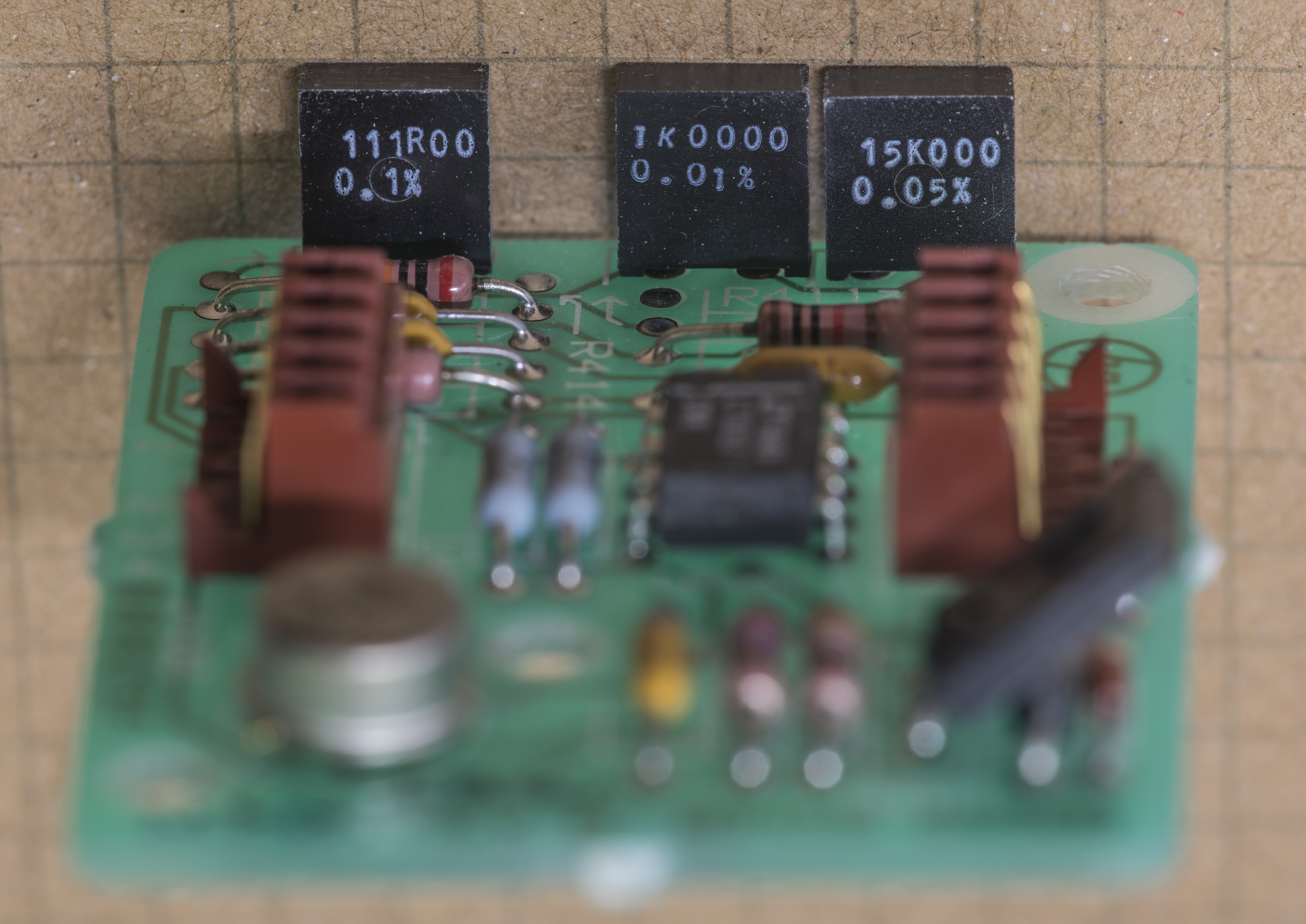
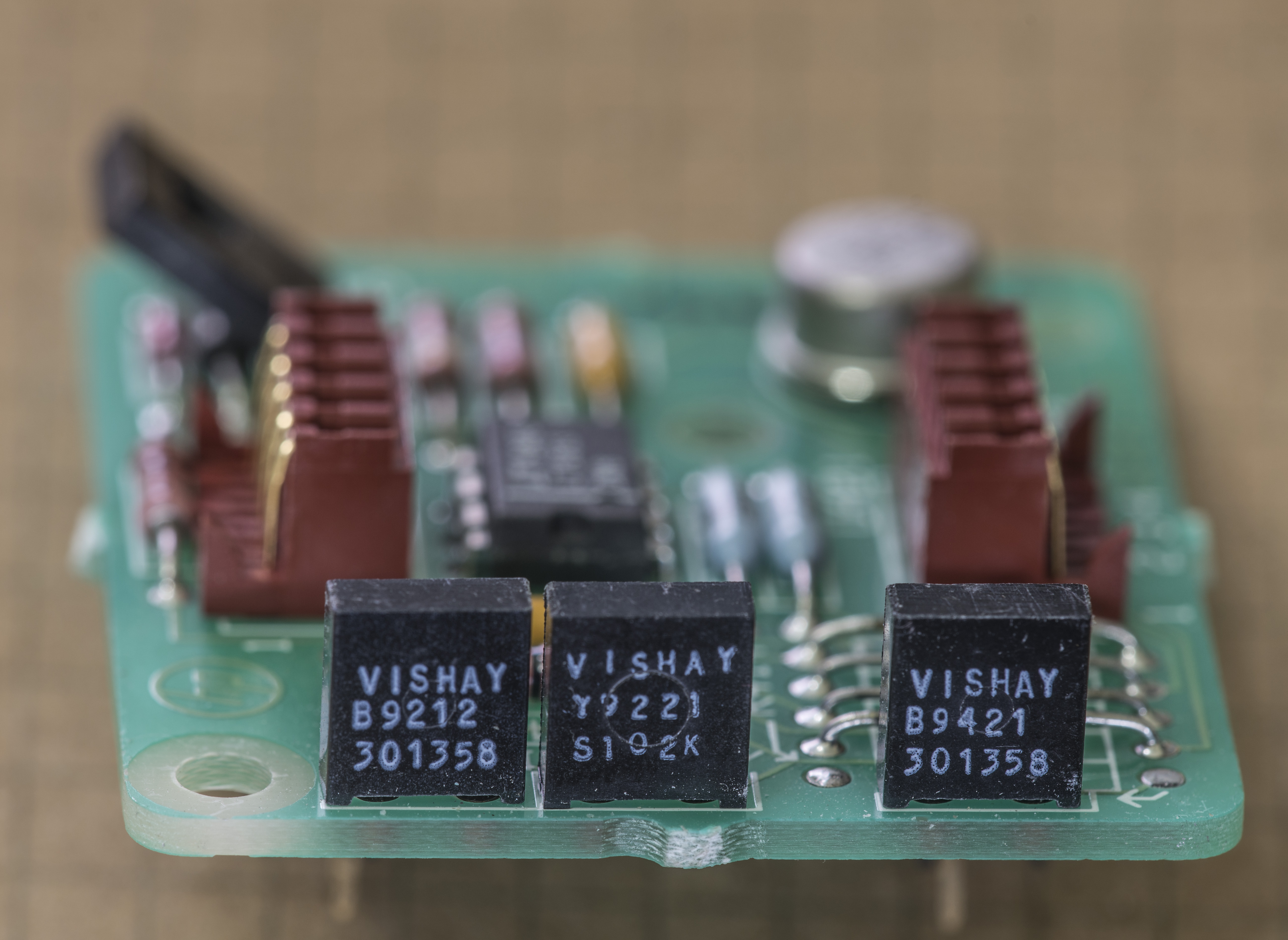
Image 104-105: Vishay foil precision stable resistors
One of the common difficulties of LTZ-based references is extreme requirements for setpoint resistors stability. It is not rare to see literally hundreds of dollars worth resistors around LTZ1000A, which itself cost 54$, directly from LT.
There is strong community discussing this interesting chip and related designs, such as here.
It’s obvious today for experienced engineers, that design team did not set target of making HP’s LTZ1000A reference most stable, given both used components, PCB layout approach and official specification of “only” 8 ppm/K. Perhaps it was done so due to cost, time and market demands back then. Below is resistor specs used in STD version of A9 board.
| _.RefDes | Resistance | Abs.Tolerance | Temperature coefficient | Type | Spec |
|---|---|---|---|---|---|
| R414 | 111 Ω | ±0.1% | ±1.3 ppm/K | Vishay metal foil | Custom, type 301358 |
| R412 | 1K Ω | ±0.01% | ±1.3 ppm/K | Vishay metal foil | S102K |
| R411 | 15 KΩ | ±0.05% | ±1.3 ppm/K | Vishay metal foil | Custom, type 301358 |
| R413 | 74.25 KΩ | ±0.1% | ±10 ppm/K | Thin film | ? |
| R415 | 74.25 KΩ | ±0.1% | ±10 ppm/K | Thin film | ? |
Table 7: Resistor specs on A9 PCBA
Rest of resistors are common 1% thin-film type.

Image 106: Perspective view of A9 DC reference board assembly
We will investigate reference performance and possible tweaks later after DMM repair.
Keysight also do provide higher-specced Opt.002 voltage reference modules (for $984 USD) and even HFL ±2 ppm/K version (only for $2195 USD :) ) for ordering, in case someone need new PCBA directly from vendor.
Here’s how 002 version look like:
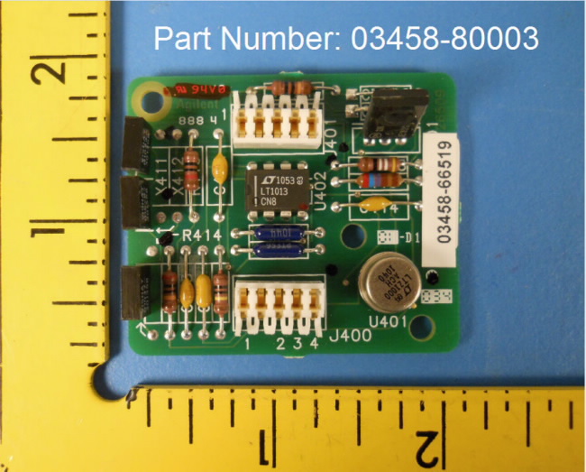
Image 107: Option 002 A9 PCBA, courtesy of Agilent website
Enough theory, let’s check our A9 operation.
To do so, I used quick setup with Keithley 2400 SMU as power source to provide +18VDC to PCBA and Keithley 2002 DMM to measure output voltage.

Image 108: Voltage output and current consumption of A9 PCBA module
After prompt warm-up, reading stabilize around +7.07421x VDC, with +26.5 °C ambient temperature. My 2002 is ~30 ppm low compared to calibrated 2001, so real voltage likely just a bit higher. Point here is, that our DCV reference board is operational and can be installed into 3458A without second doubt.
One good thing about used references, they likely to be nicely aged. LTZ1000A on this one is made in 1993, in case someone miss it.
Zeners like wine, only better with time. This is due aging process and residual stresses in silicon die. When chip just manufactured, there are lot of internal tensions and stress around elements, which is slowly stabilize over time. Its usual practice accelerated aging initial few thousand hours, by running references with high temperatures/currents, before further testing and use in normal conditions.
Also it’s very important to keep LTZ1000A reference chip isolated from airflow, as that will easily create thermal gradients and thermocouple voltages on junctions, upsetting temperature and voltage stabilization of whole reference. Factory A9 PCBA come with PTFE caps (Keysight P/N 03458-44102), effectively making own enclosure around LTZ1000A, from both top and bottom sides. I also was lucky to get one set of original PTFE caps, and decided to make CAD 3D-model, so people who may go into buying used A9 REF boards can 3D-print or use CNC to produce their own caps.
Top and bottom caps drawing with PDF
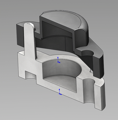
Image 109: A9 Plastic caps 3D CAD model
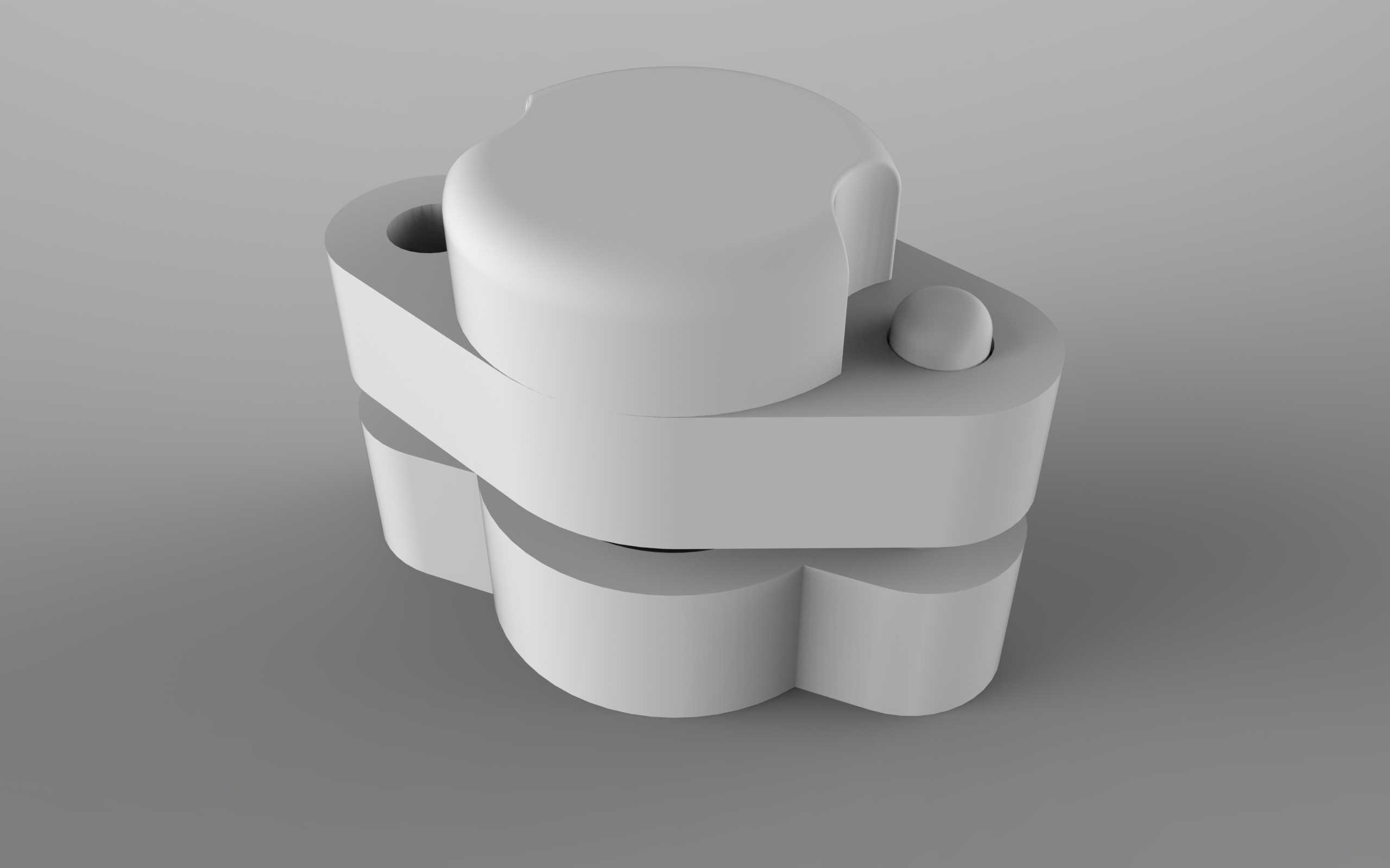

Image 110-111: A9 LTZ1000 plastic caps overview
Also sources for parts are available in Solidworks 2015 format, Top cap and Bot cap
Cap assembly 3D CAD Solidworks 2015
A10 Front/rear switch board
This little board sits at Inguard section, just near A1 relay area and have mechanical Front/Rear switch for input terminals and some protection circuits, like gas discharge tube.
Since original switch had broken locking mechanism, and also with contacts of unknown condition, I decided to replace switch to brand new one anyway. Here’s A10 PCB w/o switch:
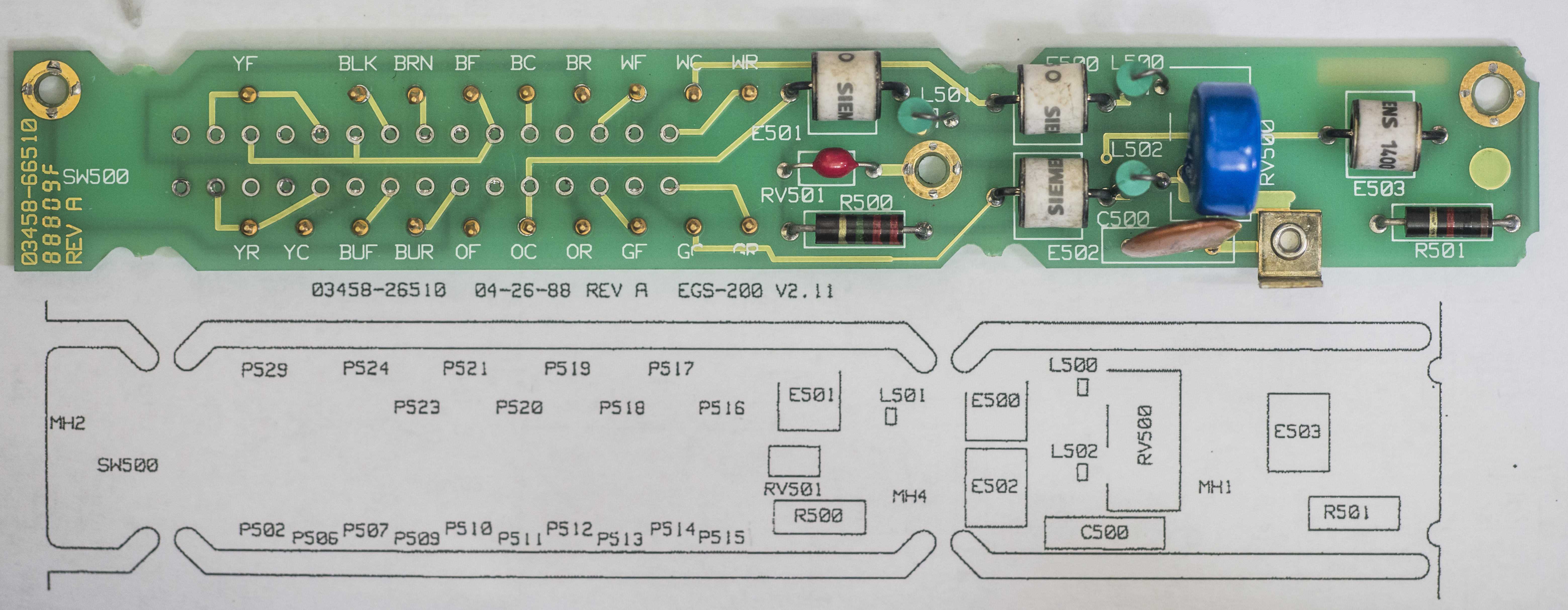
Image 112: A10 03458-66510 front/rear switch panel PCBA
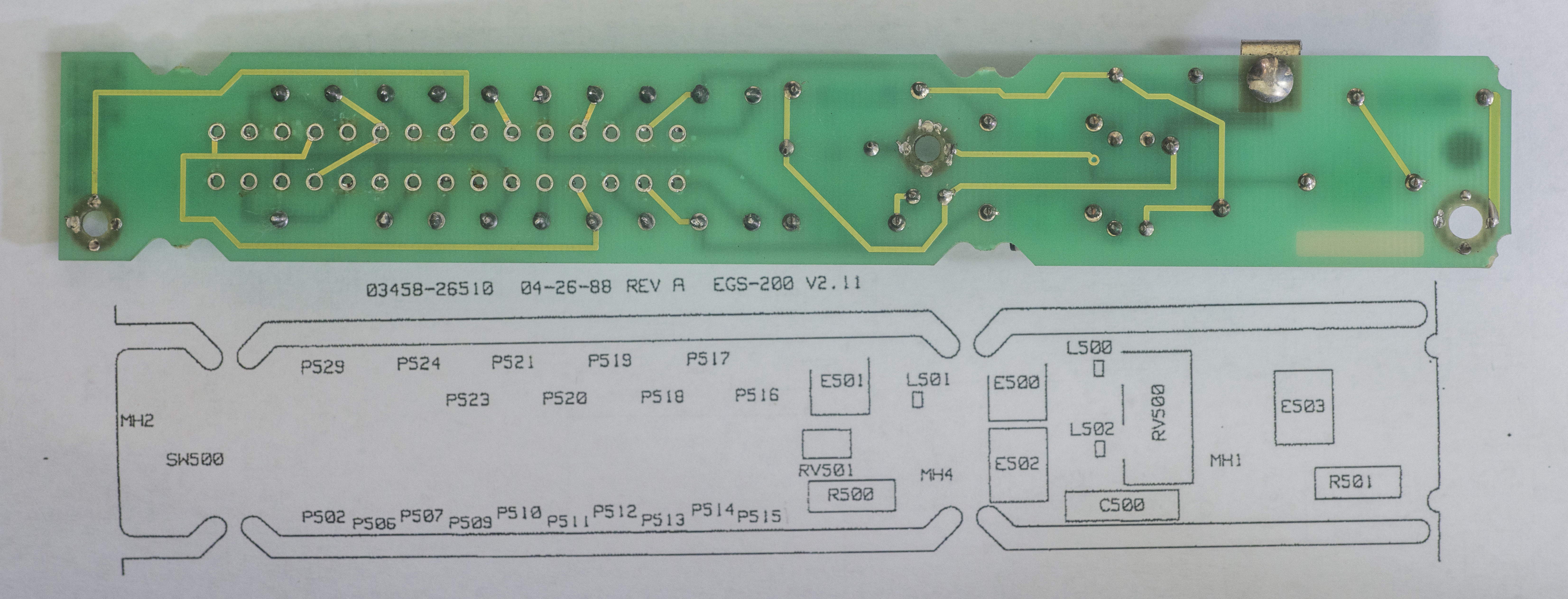
Image 113: A10 rear side of PCBA
And comparison of new and old switches:
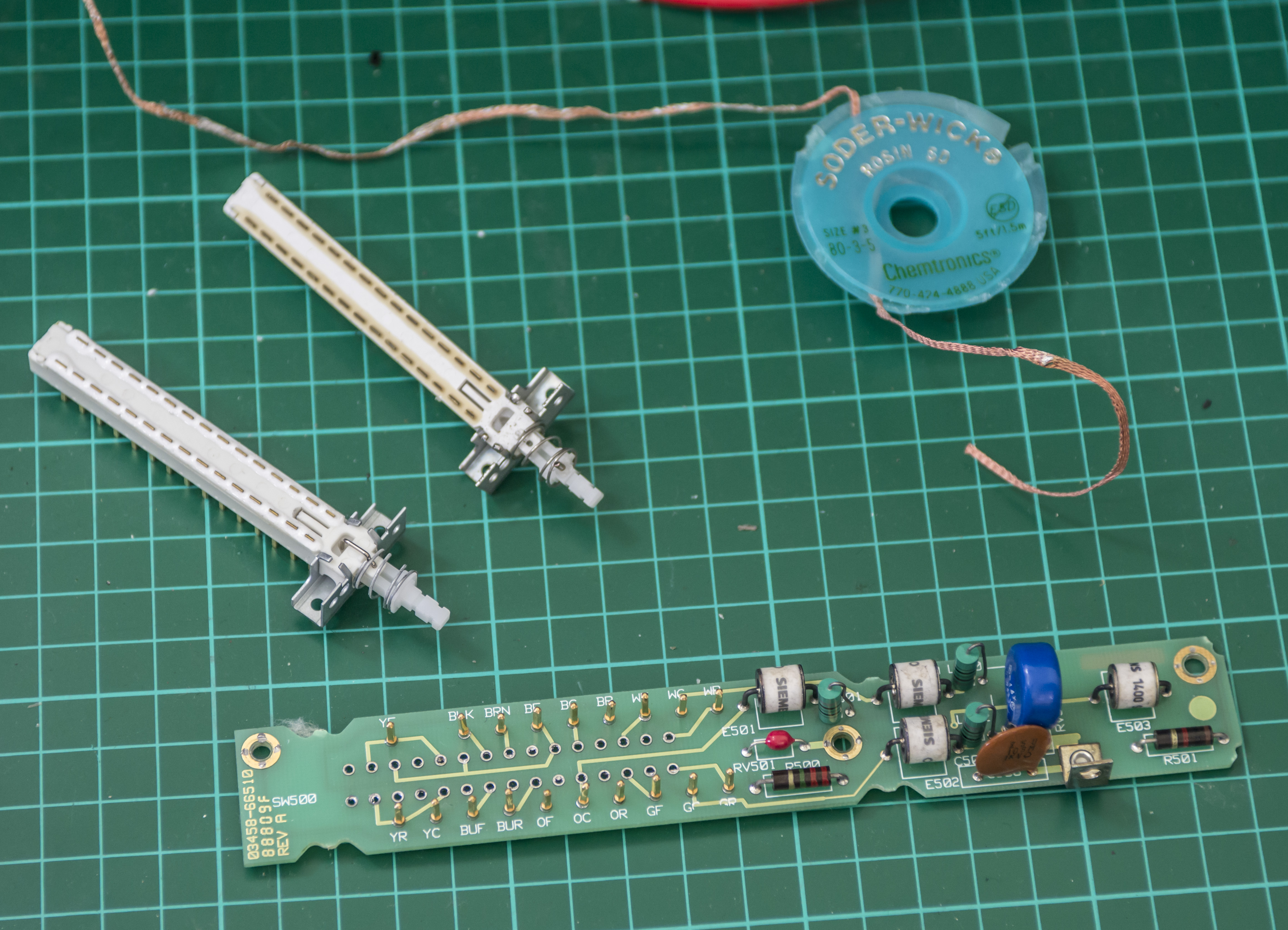
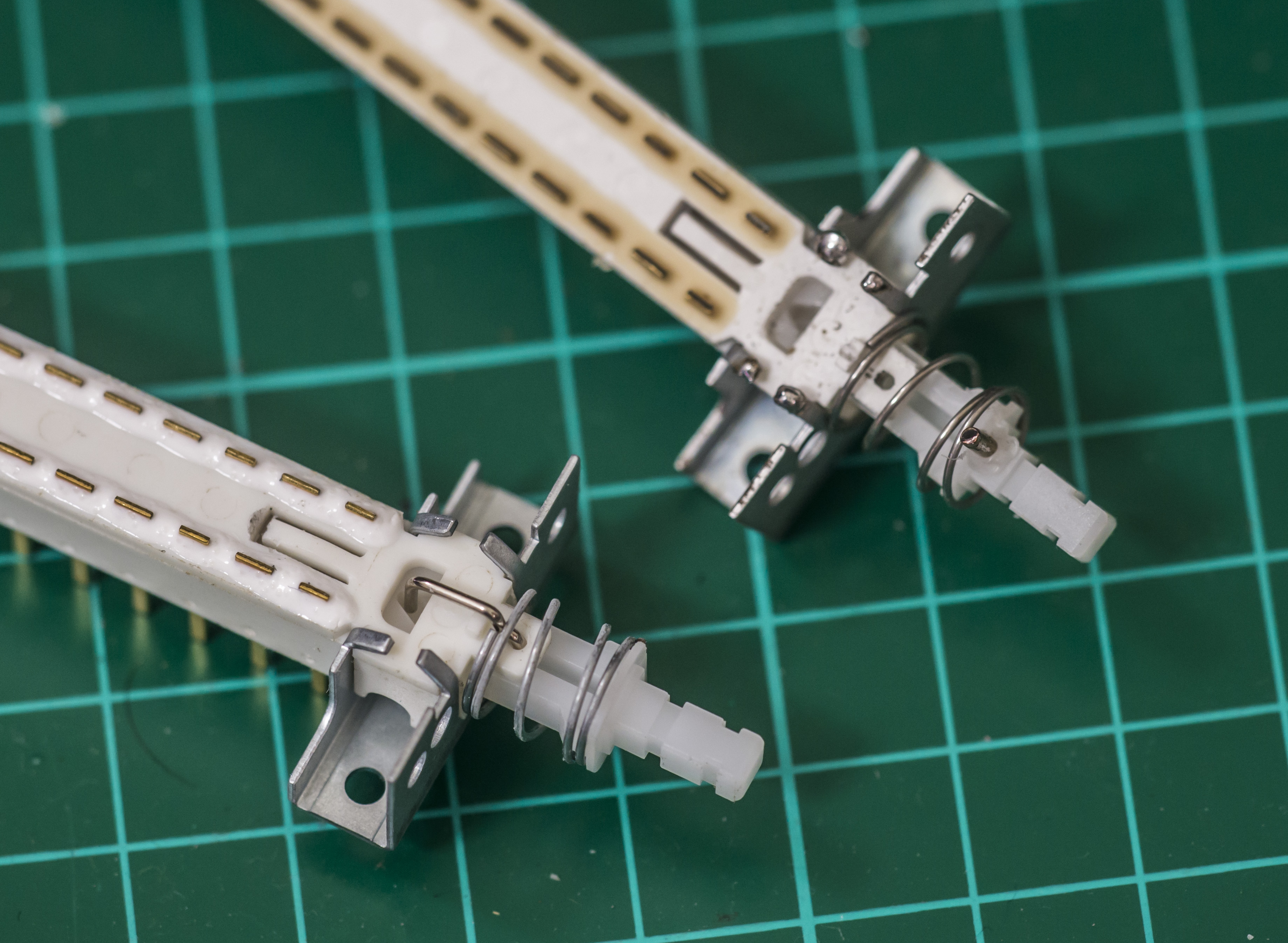
Image 114-115: Switch replacement for a new one
Switch is orderable from Keysight, under P/N 3101-2969 for $55 USD. This type switches are often cause excessive leakage and noise on measurements, or even bigger issues, like I had with Keithley 2000 repair.
Replaced old one by desoldering with solder wick and thorough cleaning board with isopropyl alcohol. This is crucial to keep this PCB clean for proper operation of high ohms ranges and low current modes.
All wiring color is marked on PCB, so it’s easy to connect all harness. For example for current input yellow wire marked as – YC (Yellow common, wire going to A1 PCB), YF (Yellow front, going to front panel terminal block), YR (Yellow rear, going to backside terminal block). Make sure you keep wiring, PCB surface and switch clean to avoid leakage, which would corrupt measurements.
Chassis repair
I got used bezel off eBay in good condition, to save some money on this project, as it’s just mechanical part to keep meter in one piece. New one on bottom side, old busted rear bezel is on top:

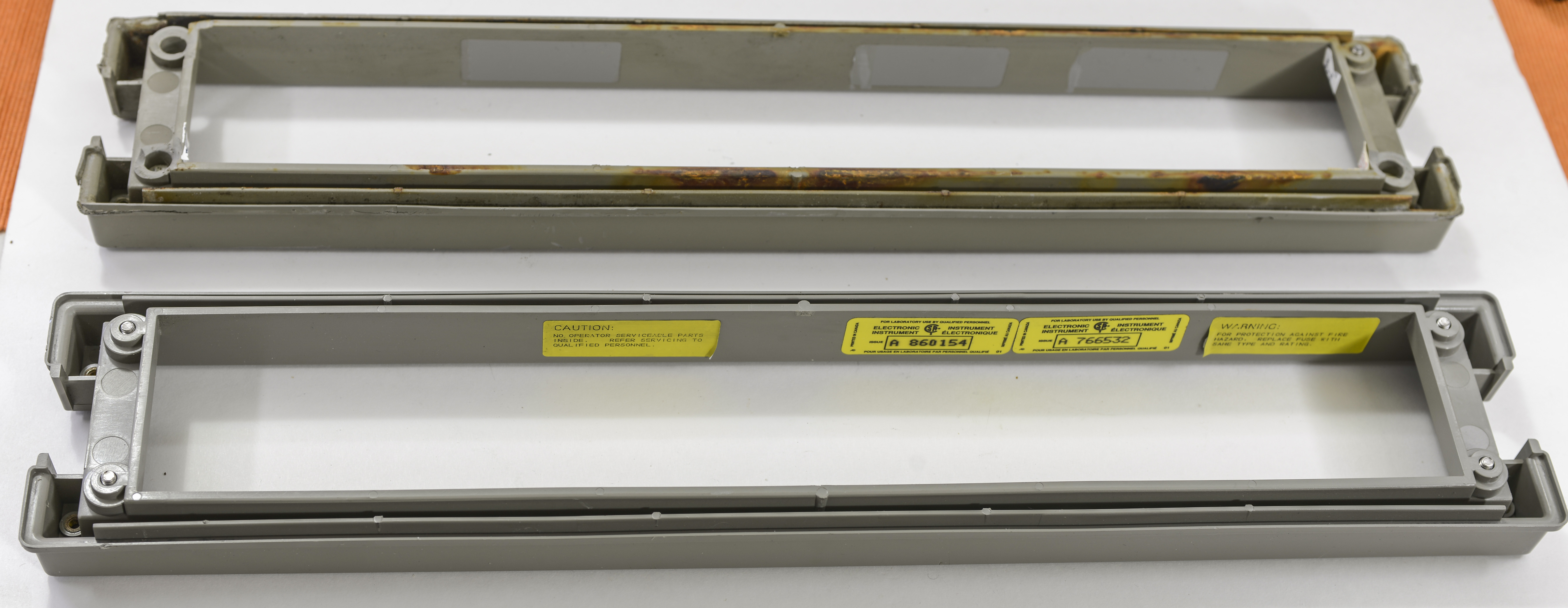
Image 116-117: Rear plastic bezel replacement
Original unit’s bezel had three out of four screw mounts destroyed, so it was not holding well.
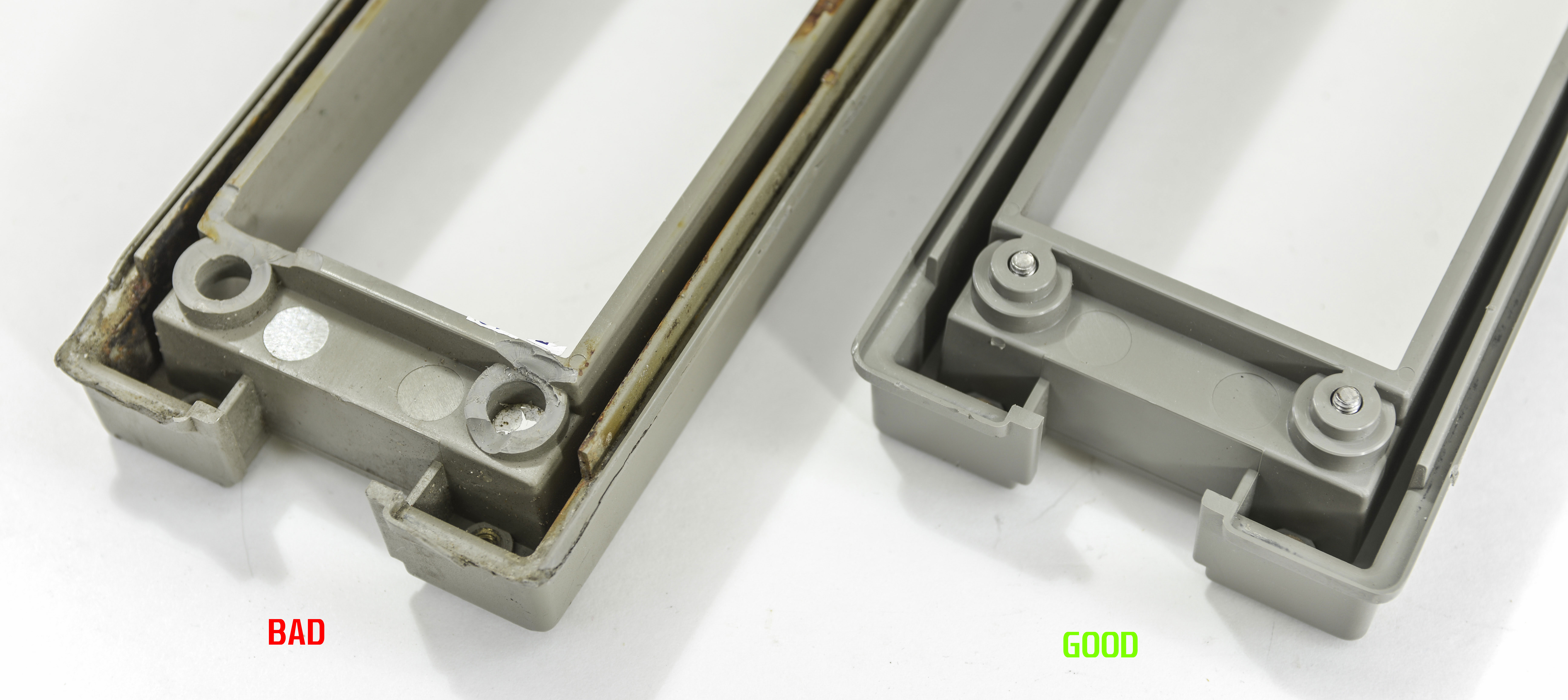
Image 118: Damaged mounts on old bezel
How the hard part, removing rust and dirt off the steel frame.
STEP 0. Remove all boards and parts from chassis.
This is easy operation, system design made very serviceable and everything is modular.
Remove boards carefully, handle them only by touching corners, and do not touch any components on PCBA’s inside guarded analog box. Oil and dust will contaminate surfaces and cause current leakage, thus ruining performance of analog circuitry. Boards interconnected between with ribbon cables and chassis-thru pin headers. Note screws from each board and chassis elements, it will help you later to assemble all back in right order.
STEP 1. Remove mains socket and BNC ports and prepare tools
Now you have bare chassis frame separated, but some parts still on it. To remove rear BNC ports release connector nuts and desolder signal wire.
Removing fan is easy, just detach fan dust filter and release Torx screws holding fan in place.
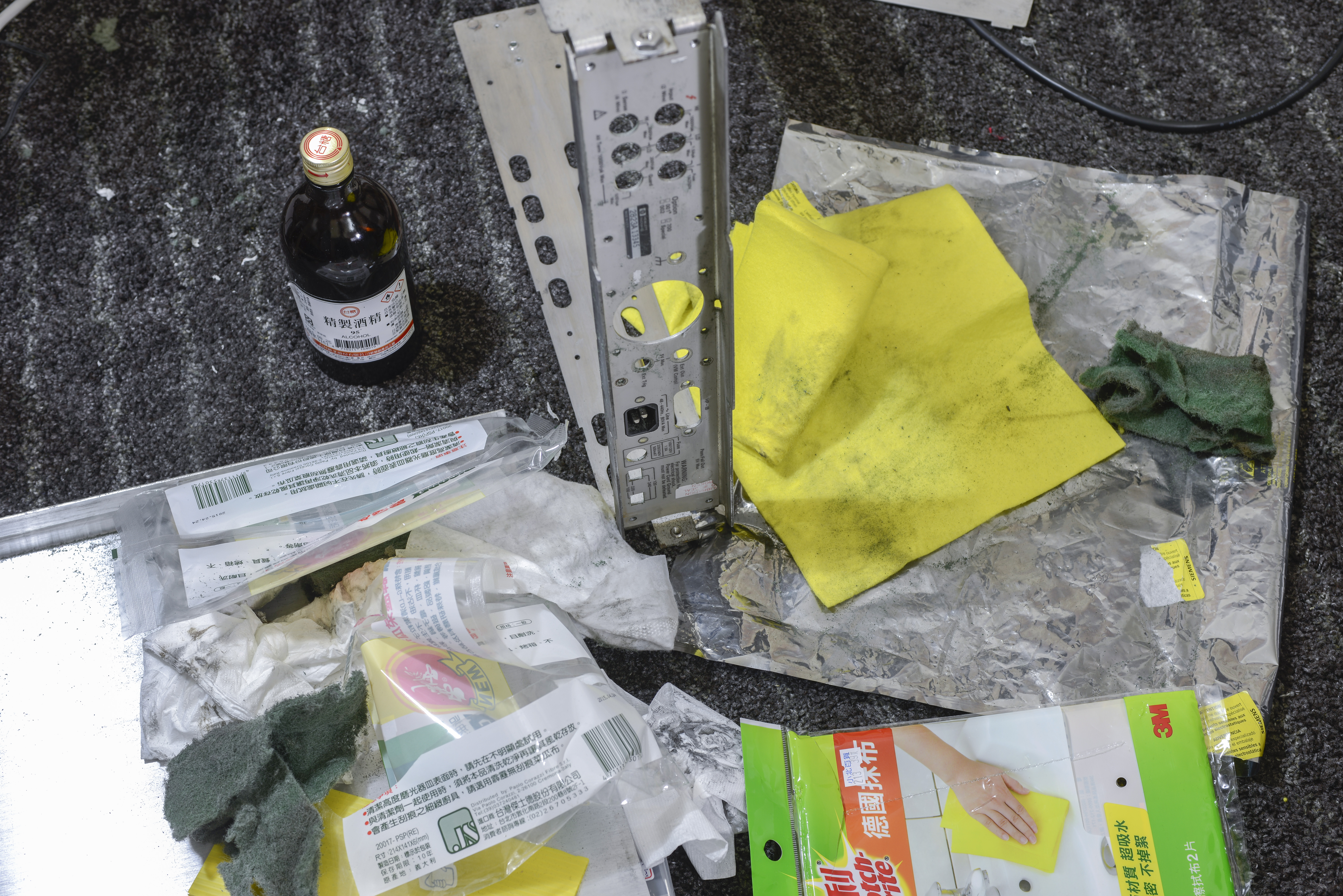
Image 119: Cleaning rust of with 3M Scotch-Brite and alcohol
STEP 2. Clean steel frame from dirt and rust
I used 3M Scotch-Brite with 95% alcohol to remove rusty particles first, then proceed with sandpaper, grit 200, 400 and finishing 600 to get nice shiny metal.
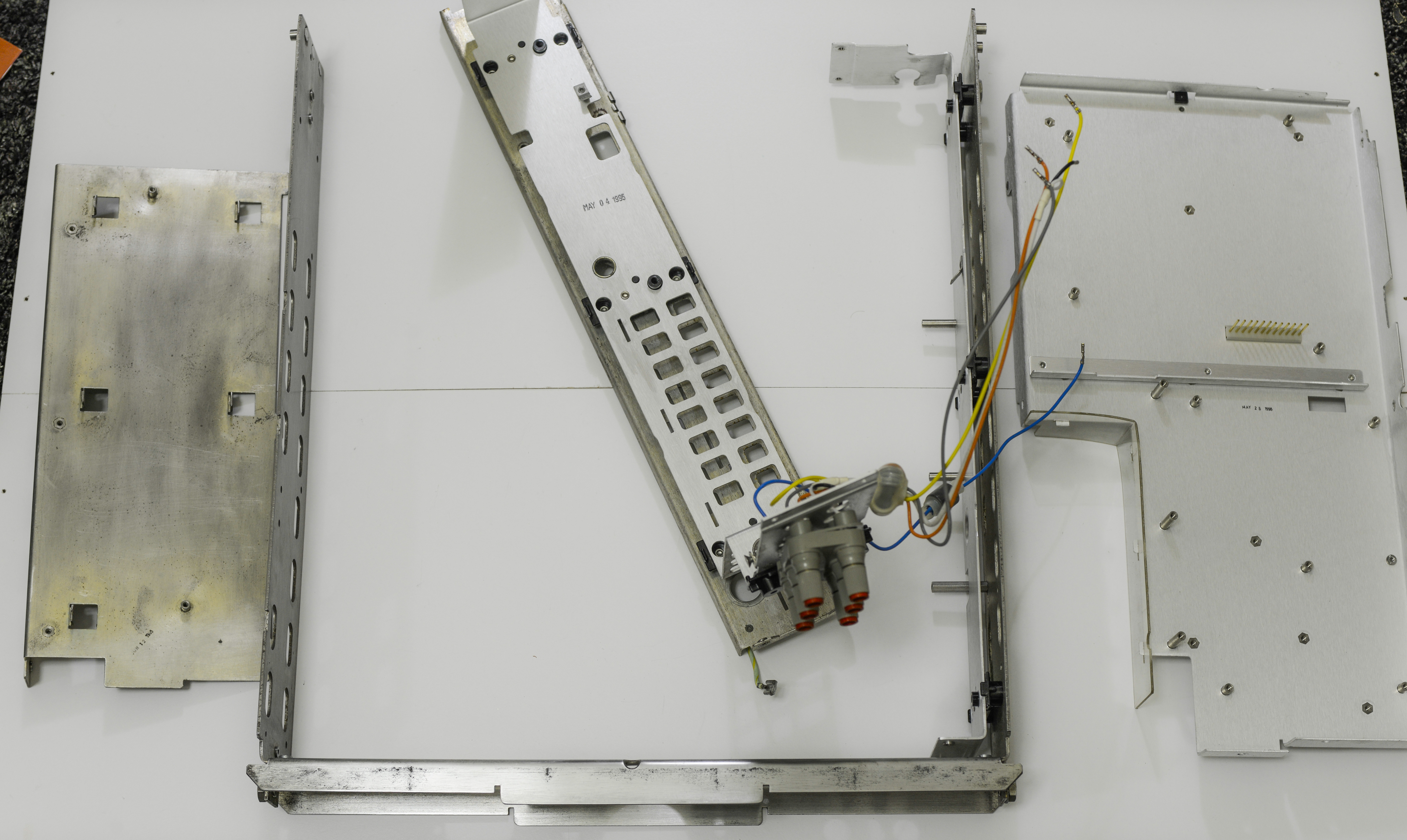
Image 120: Frame parts separated
Aluminum inner frame have date code marks, MAY 04 1995 and May 23 1995, confirming conspiracy theory that all meter boards, except A5 Outguard controller are ~1995 year, while A5 is was swapped out to older 1990 board.
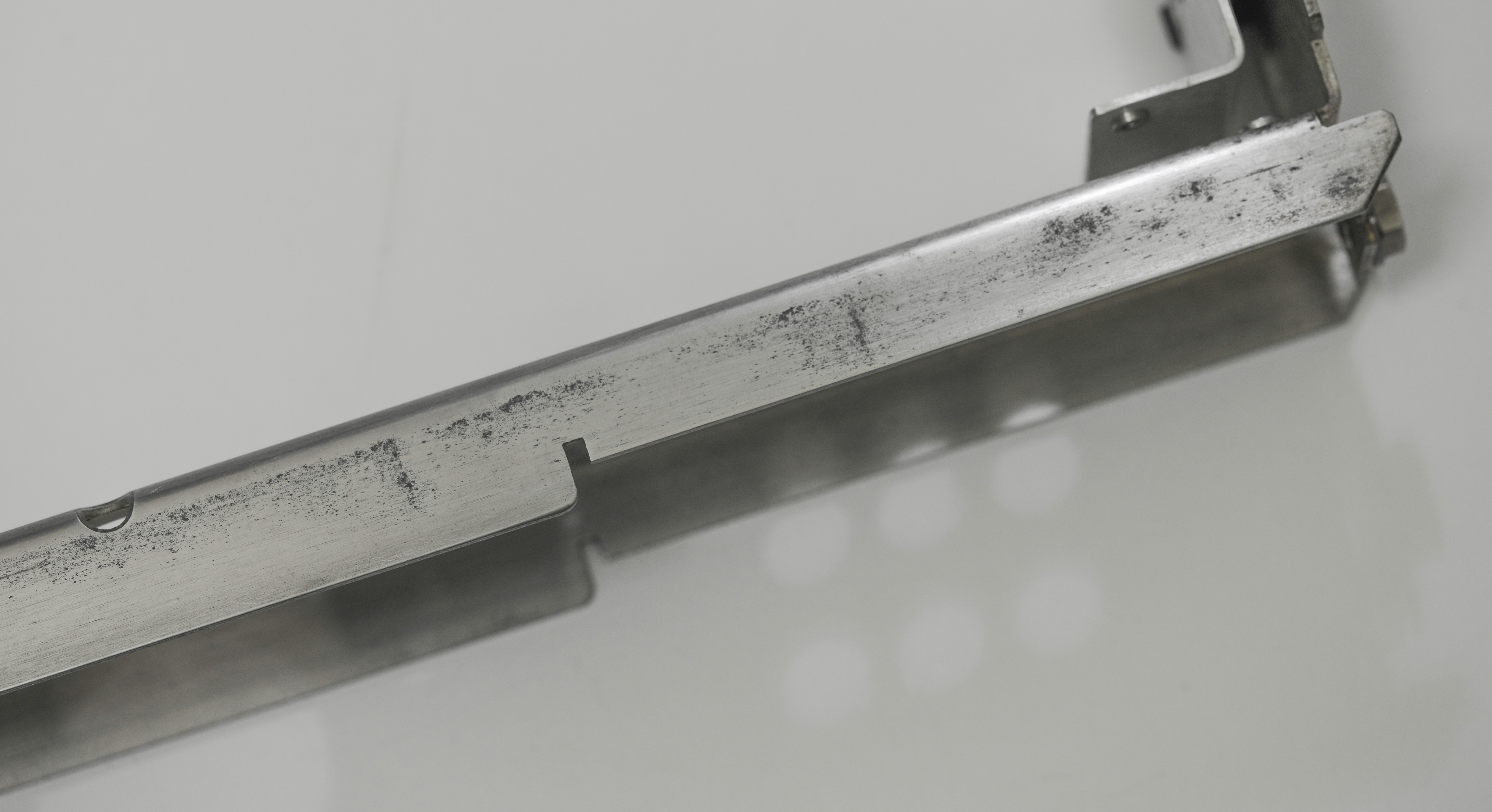
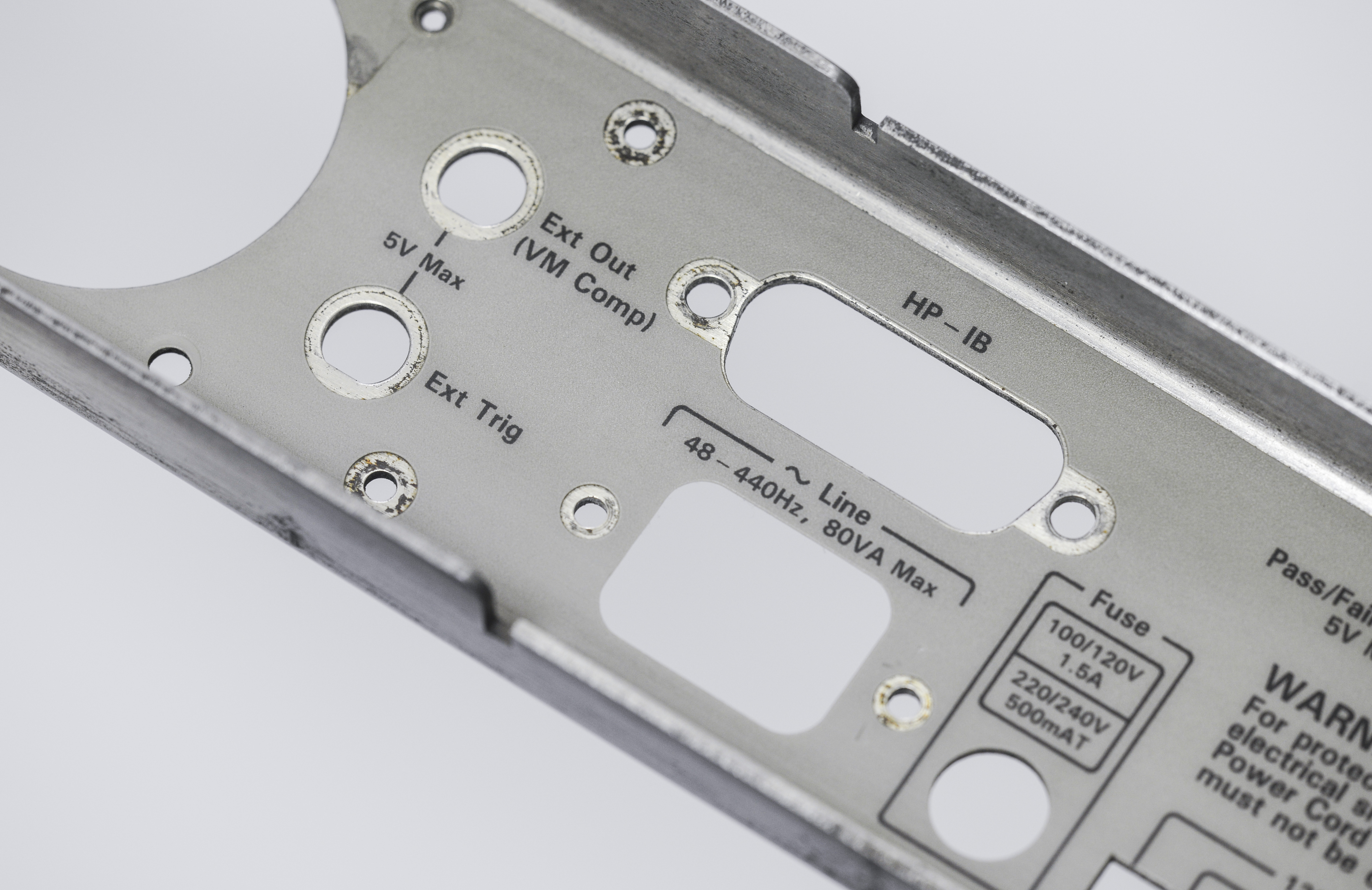
Image 121-122: Cleaning in progress, after 3 hours
Suspicions to explosions Schaffner FN 323-3/05 IEC mains filter socket was fixed to chassis with rivets. Just push it out with rod and little hammer action, and remove the filter. I’ll use suitable screws instead with new socket.
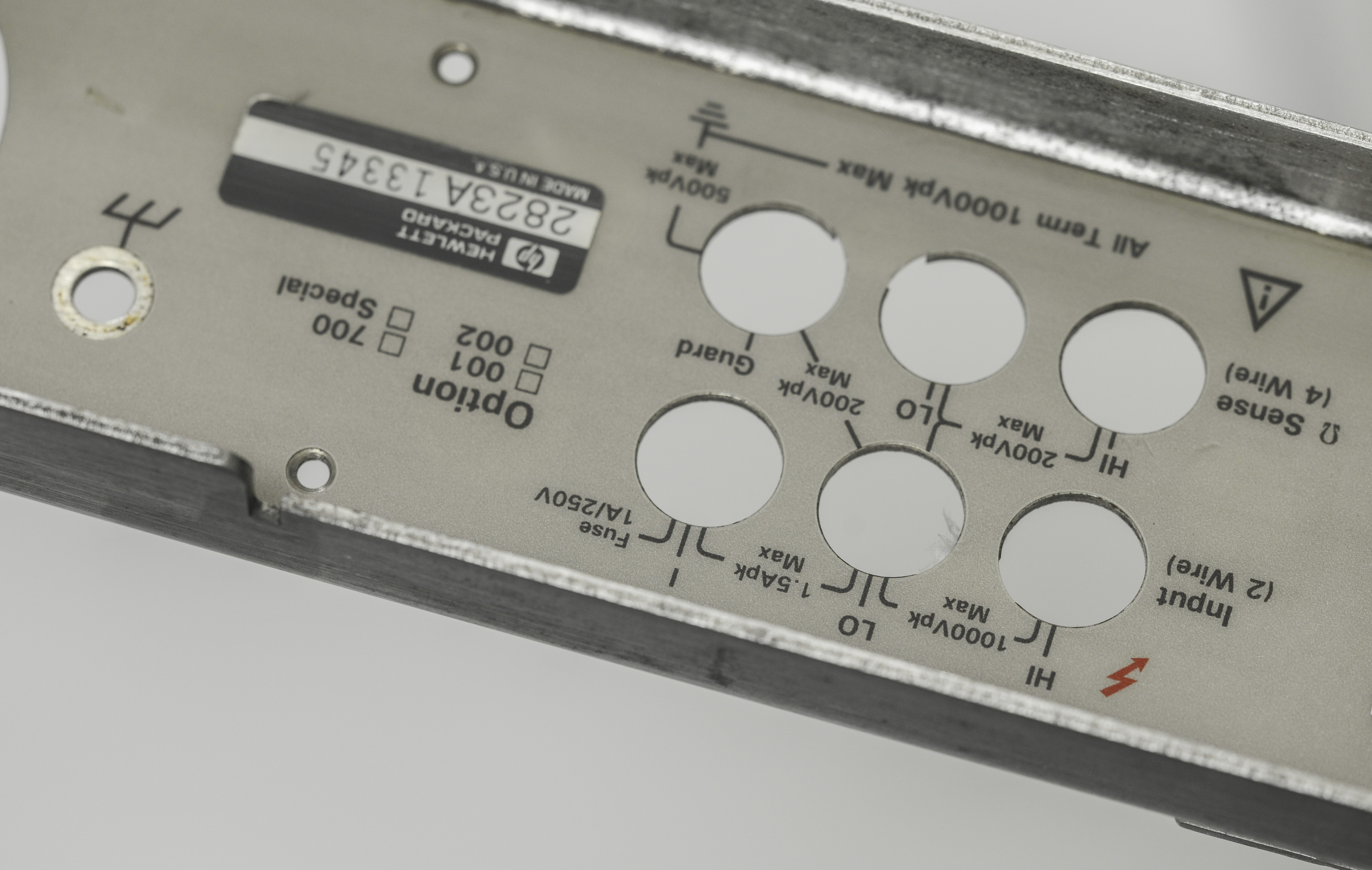

Image 123-124: Rear side. Mylar plastic is alcohol-resistant
Few spots around nuts and corners still need some attention, will do it later with finer tools, just before assembly.


Image 125-126: Sides of chassis after cleaning
Use paper towels with alcohol to remove any metal particles and dust off the frame. You don’t want little bits of metal dropping off to your electronic PCBs, causing possible disasters. Pay extra attention to terminals area, as any conductive contamination will be a path for leakage and errors in measurements.
I swiped all surfaces many times till paper come out white and clean as a result. Avoid water to touch frame, to prevent rust and corrosion on fresh metal.
STEP 3. Exterior cleaning, covers
This is what we had originally:
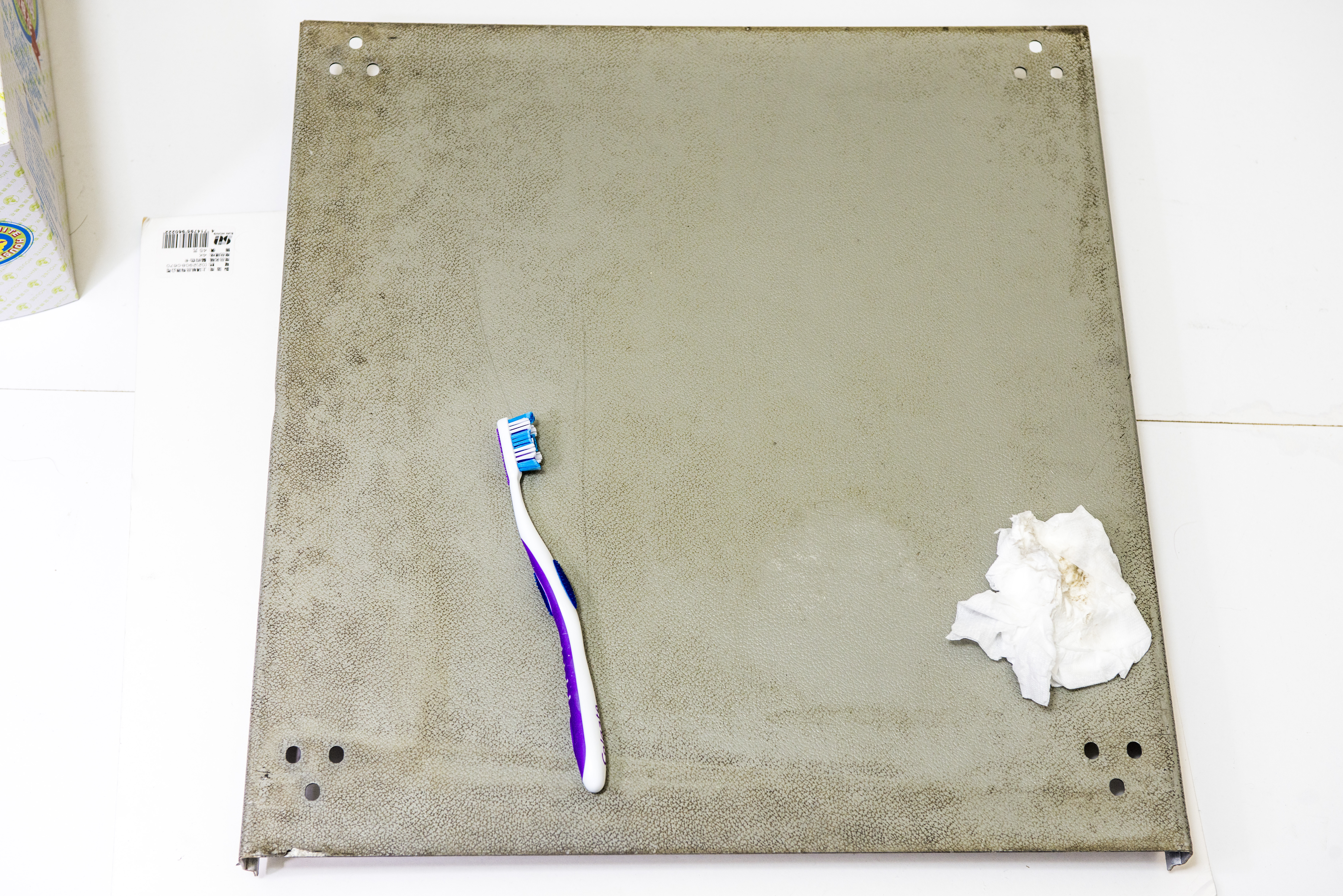
Image 127: Dirty cover, prior to cleaning
Dirty and nasty, but not hopeless. With great help of abrasive 3M Scotch-brite and half a bottle of alcohol (not drinking, like some might thought!), everything is possible.
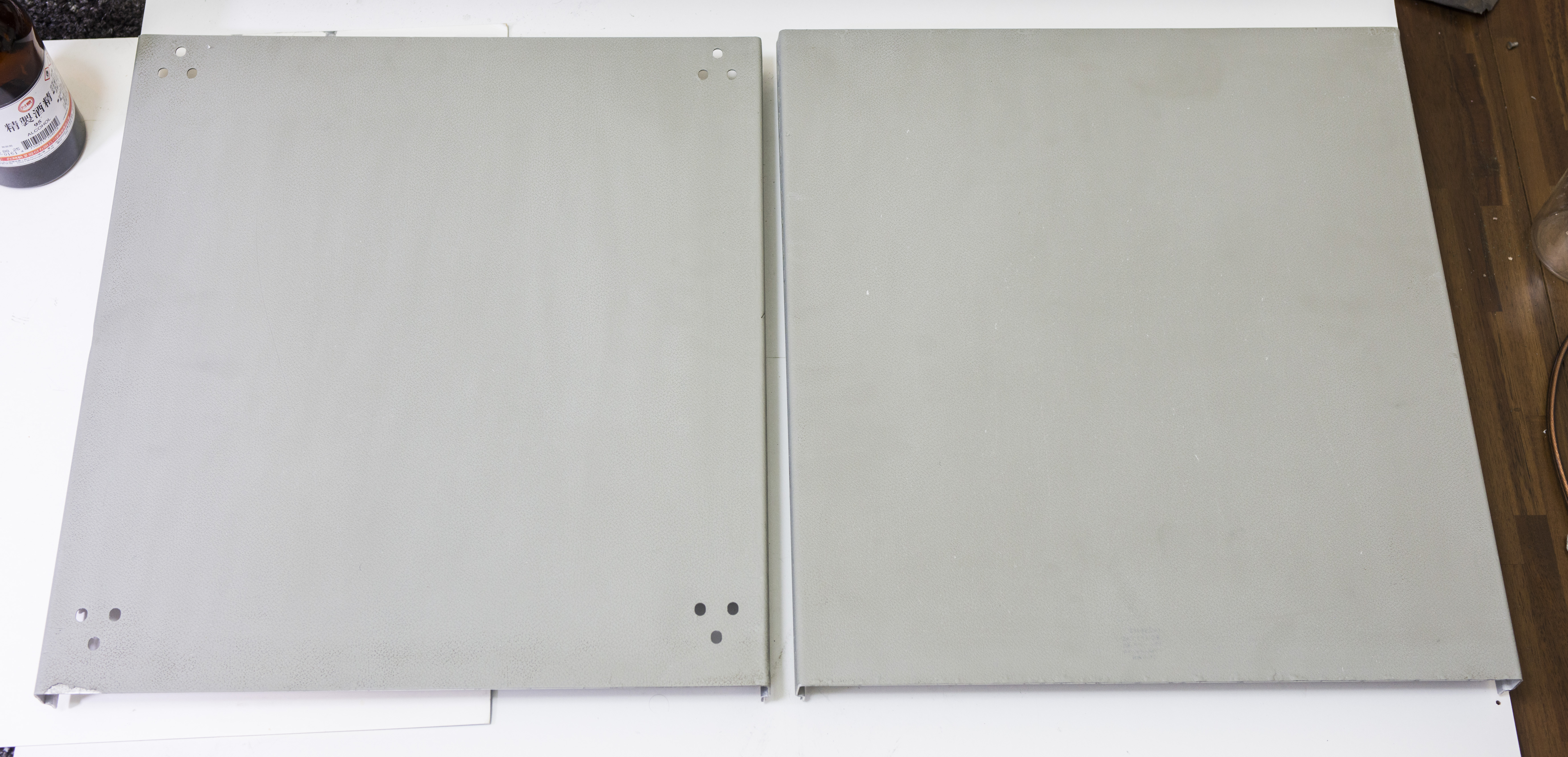

Image 128-129: Covers after cleaning with alcohol and water bath
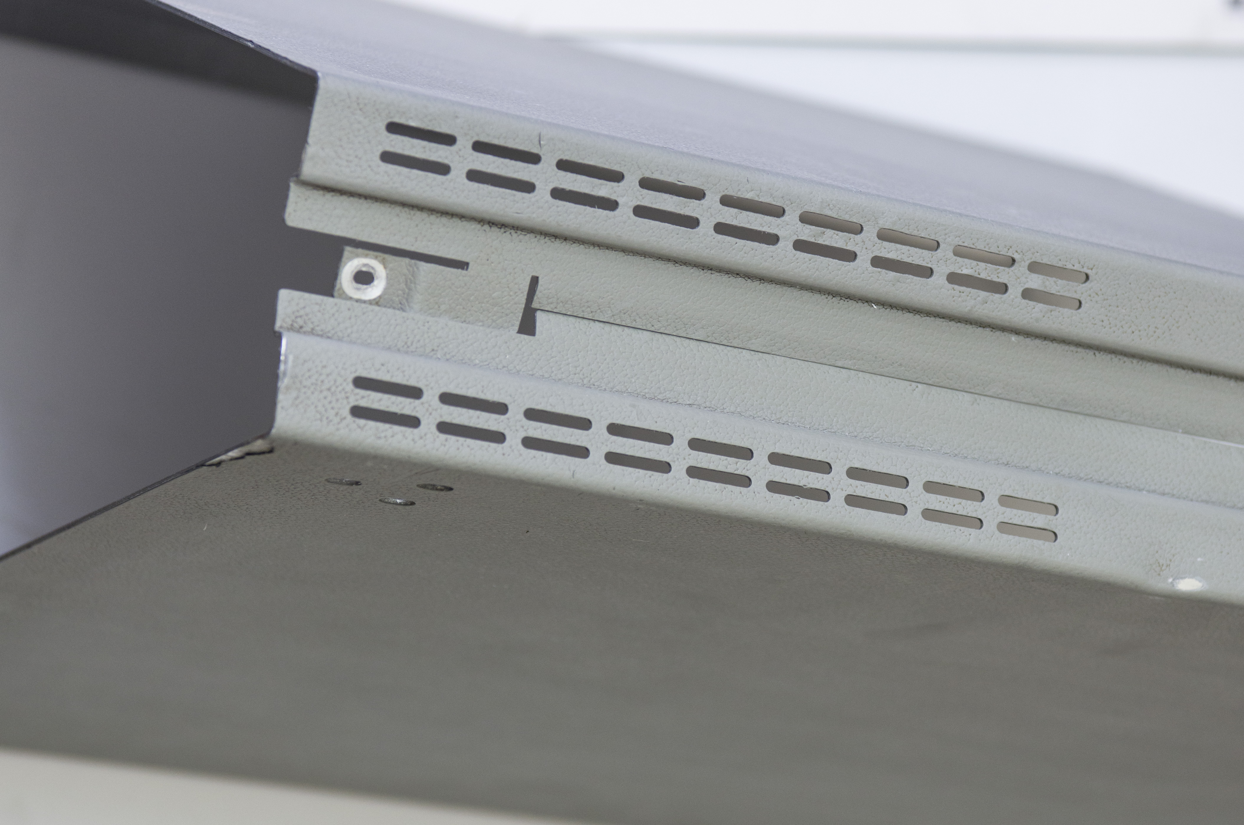
Image 130: Cover sides
Looking much better now. Few final touches will be done prior to final assembly, but we can work with this.

Image 131: Ready to install on chassis
STEP 4. Front panel cleaning
Time to clean front panel from alien stickers. Can say it’s in mint condition after, well satisfied with front face condition repair.
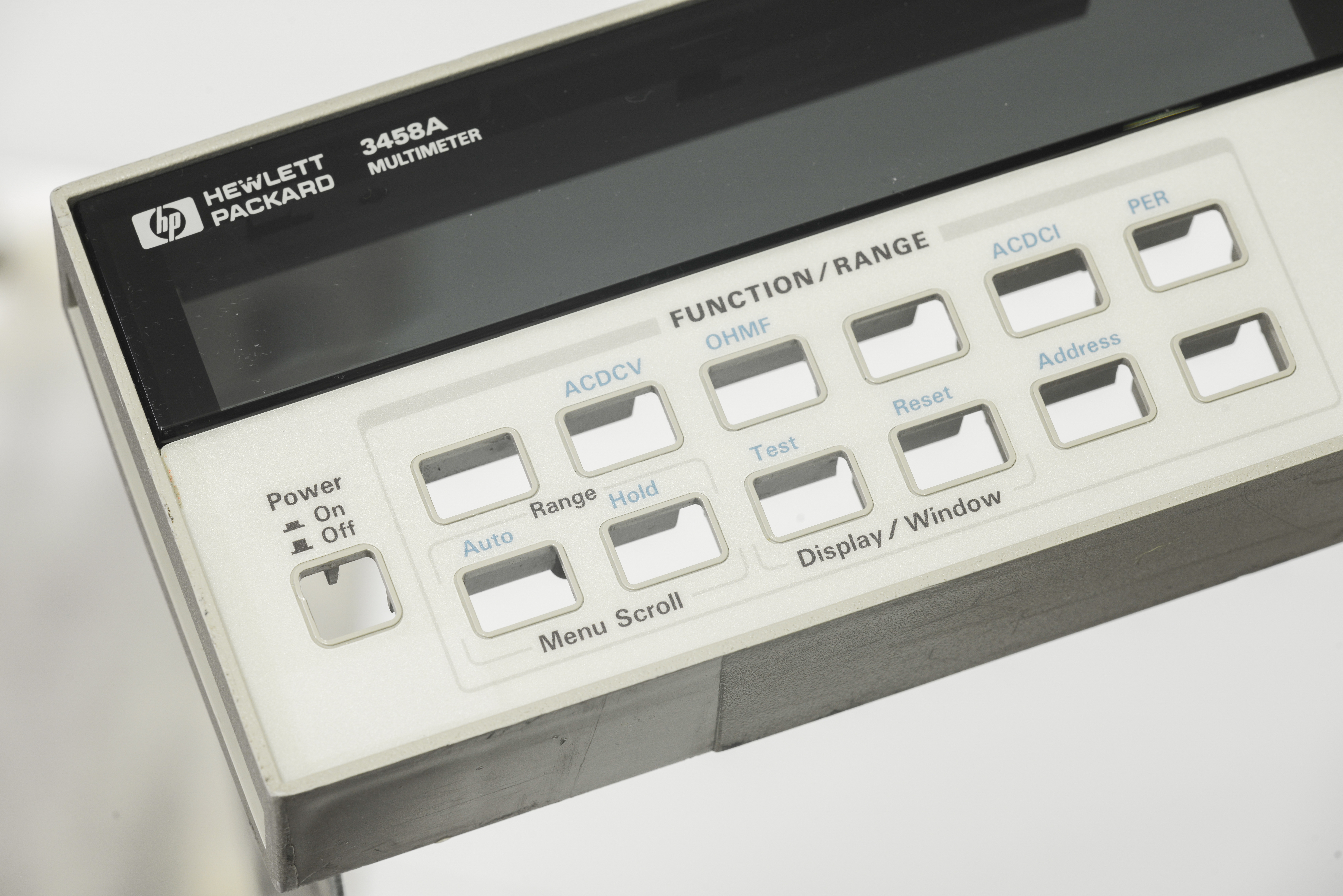

Image 132-133: Front panel plastic cleaning
Cleaned keypad as well, who knows whose dirty fingers pressed teh buttons. :)
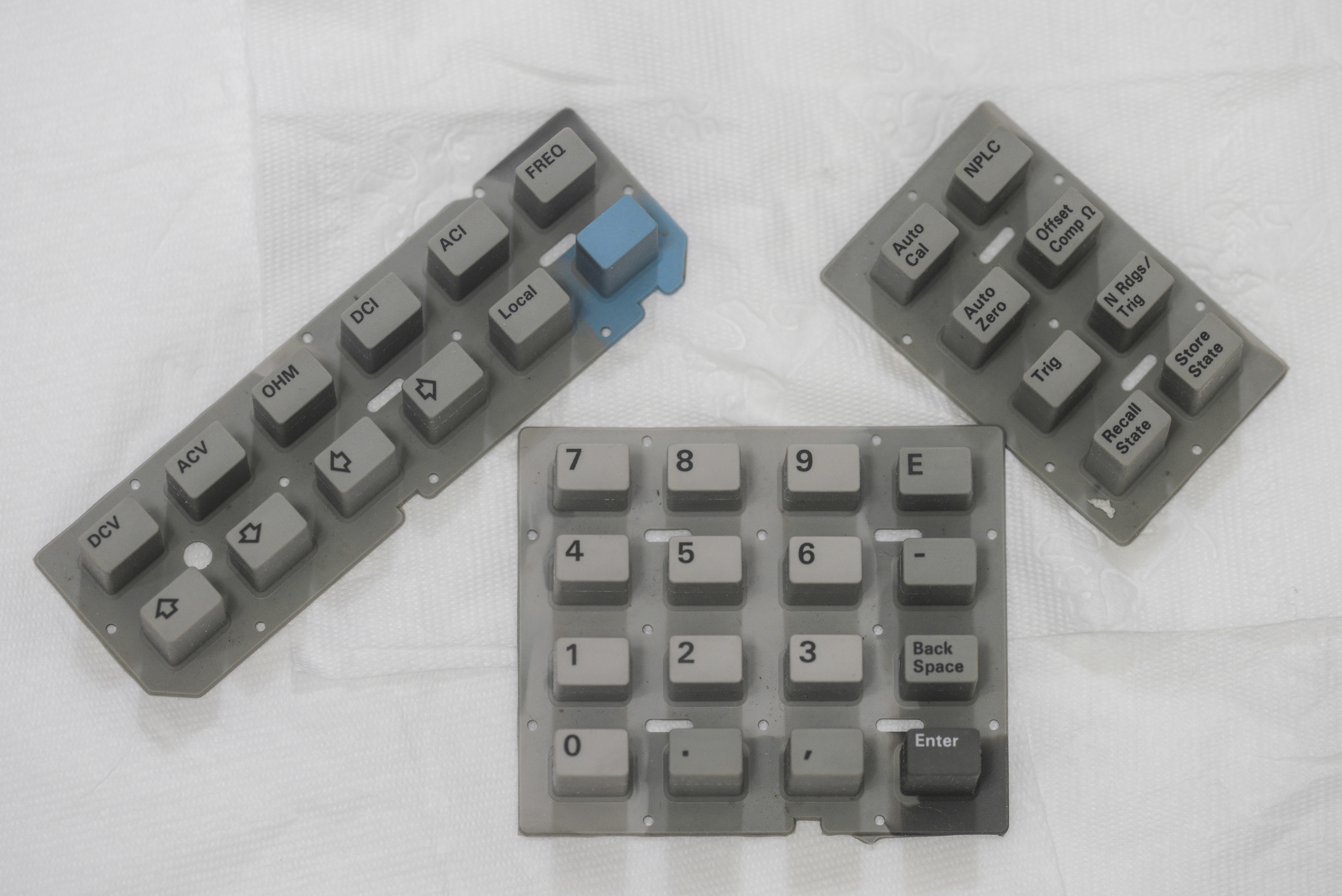
Image 134: Keypads after alcohol bath and wash
Diagnostics
Now after all initial repairs are complete, it’s time to power it up and test main functions and operation, and likely jump into more complex debug & repair.
For minimal test meter would need to have boards A4,A5,A6,A3 assembled and properly connected. After quick voltage checks I went ahead and install all boards in chassis already.
Video 2: DMM assembly, initial checks. 6 hours worth timelapse, 0.142 FPS , 4K resolution, using my repaired Nikon D3. 1880 photos.
First power on – test power supply voltages:
| Rail | Measured value | Result |
|---|---|---|
| +5V | +5.012 VDC | PASS |
Table 8: Test result for main 5V
Front panel reports REQUIRED ACAL ALL, then quickly passing TEST RAM, TEST CHECKSUM and advances to TEST HARDWARE.
After about 5 seconds unit have one short beep and error message ISOLATOR FAILURE. This meaning digital side cannot talk to digital side of Inguard section via isolation interface.
Here’s simplified block diagram of what interfacing look like:
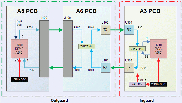
Image 135: Inguard isolation interface block-diagram
Basically it’s one unobtanium ASIC on A5 board trying to communicate with another unobtanium ASIC on A3 board, and something somewhere going wrong.
If there is problem with either ASIC, it would be very hard to find replacement without buying new expensive boards. Let’s try troubleshooting on circuit level first, and hope for the best.
Optical cables are simple plastic fiber, and pretty easy to check, since used receivers and transmitter are using 660nm light, which is visible red. I can see red light on transmitter, and swapped cables without effect, having same error. This gives us idea, that optical fiber cable is okay, but something on boards is faulty.
When meter stuck on ISOLATOR FAILURE message it tries to send data, activating J102 Transmitter. If constant 660nm light directed on J101 receiver during meter power on, it resets itself in loop right after testing RAM, so likely that receiver path on A6 board is working.
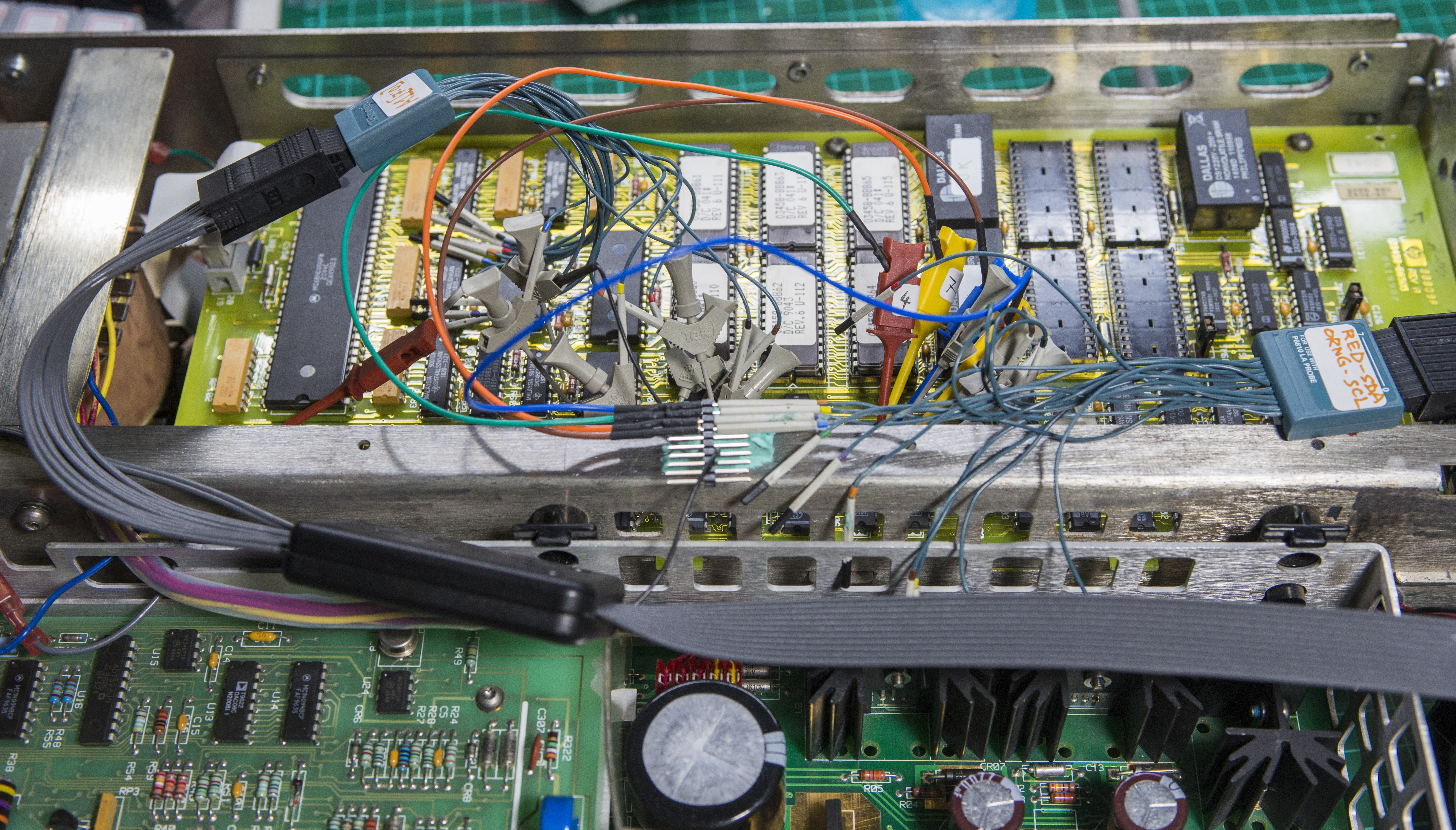
Image 136: Logic analyzer signal testing
After initial testing, suspect were U700 ASIC and U106 MMI 8L14 PAL with HP 03458-88804 mask, but measurement with TLA714 logic analyzer on A5 and A6 PCBA quickly revealed that transmit signal from A5 to A3 PCBA stops just before J102 optical transmitter.
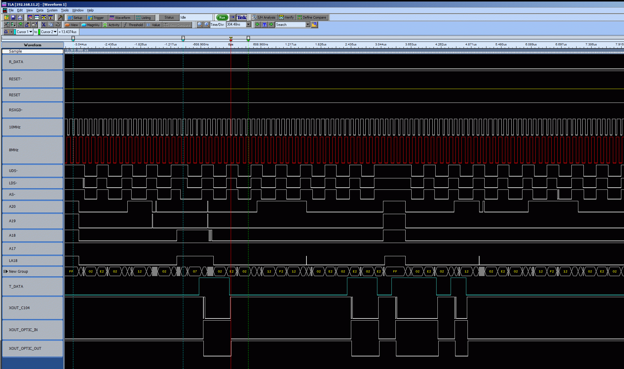
Image 137: Signal capture
Signal path section on schematic of A6 PCBA:
![]()
Image 138: VersaLink optical transmitter schematics from CLIP
One thing I notice before, LED light on J102 is really dim, could be also show actual problem with transmitter diode. Since it was easy, I actually swapped J102 with J303 before (which used for external triggering BNC ports), but result was same, so could be both transmitters are faulty.
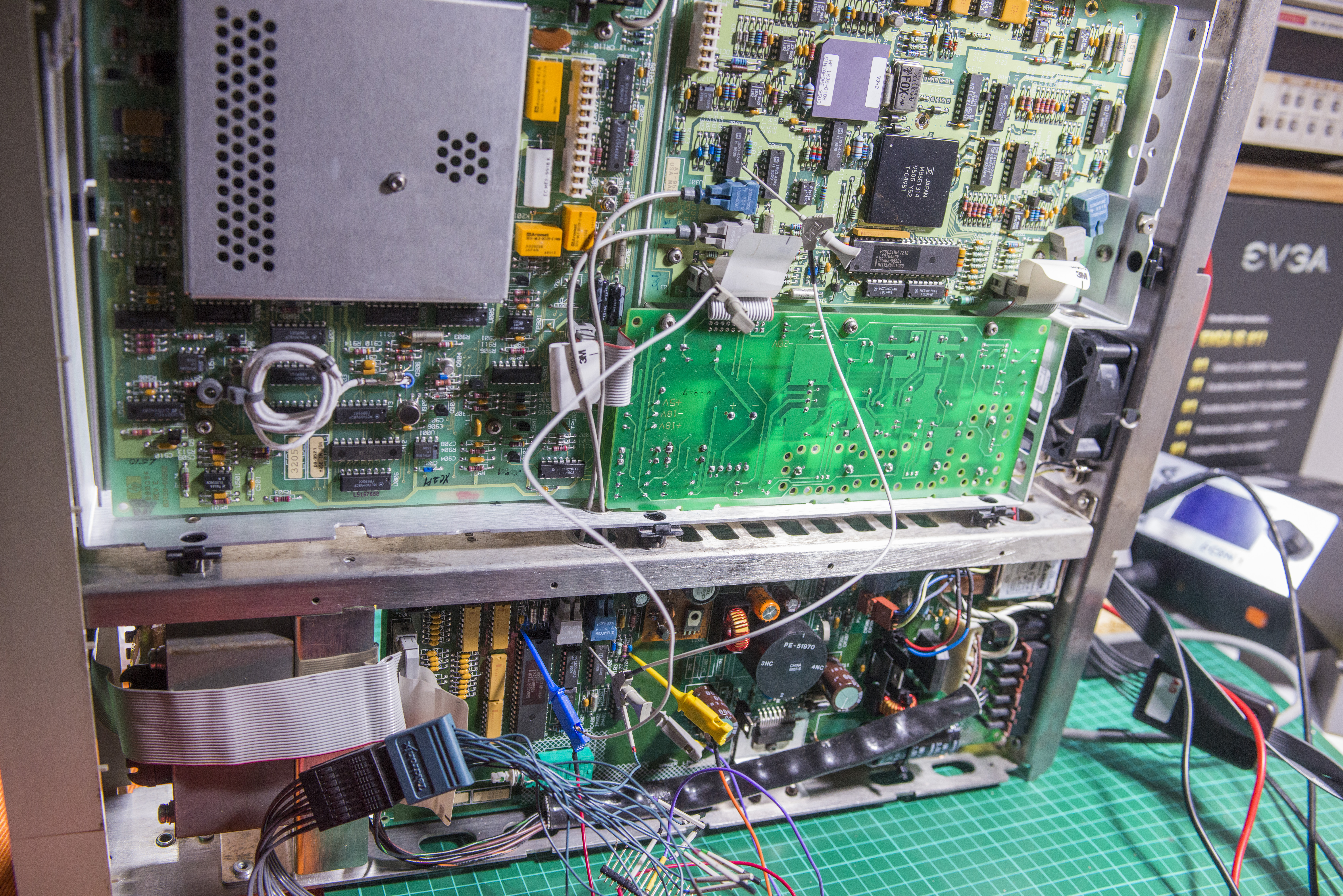
Image 140: Shorted path to bypass isolation. Use care!
Transmitters and receivers are orderable from DigiKey, they are Avago HFBR-1521Z and HFBR-2521Z.
These Avago parts are NOT pin-to-pin compatible with older boards, which using HP HFBR-1501Z and 2501Z parts!. Some jump-wiring and trace cutting required if you want install new Avago parts.
Cable assembly is available as well, DigiKey 516-2090-ND for 1m
To test this I had bypass transmit isolation path by adding a shorted between anode of A6 CR101 diode to U302 pin 9 input on A3 A/D board. And YES, meter booted and let me see front panel UI.
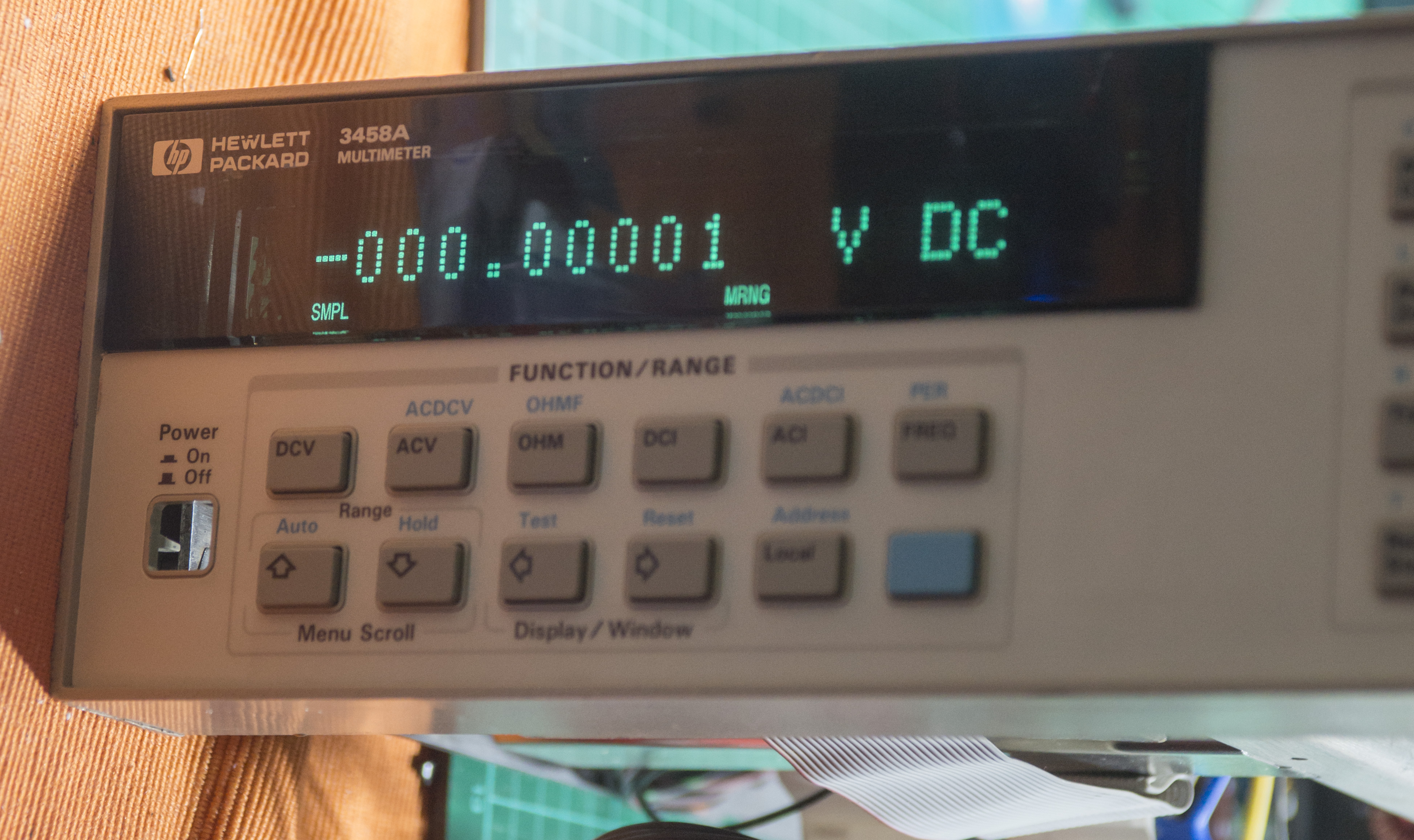
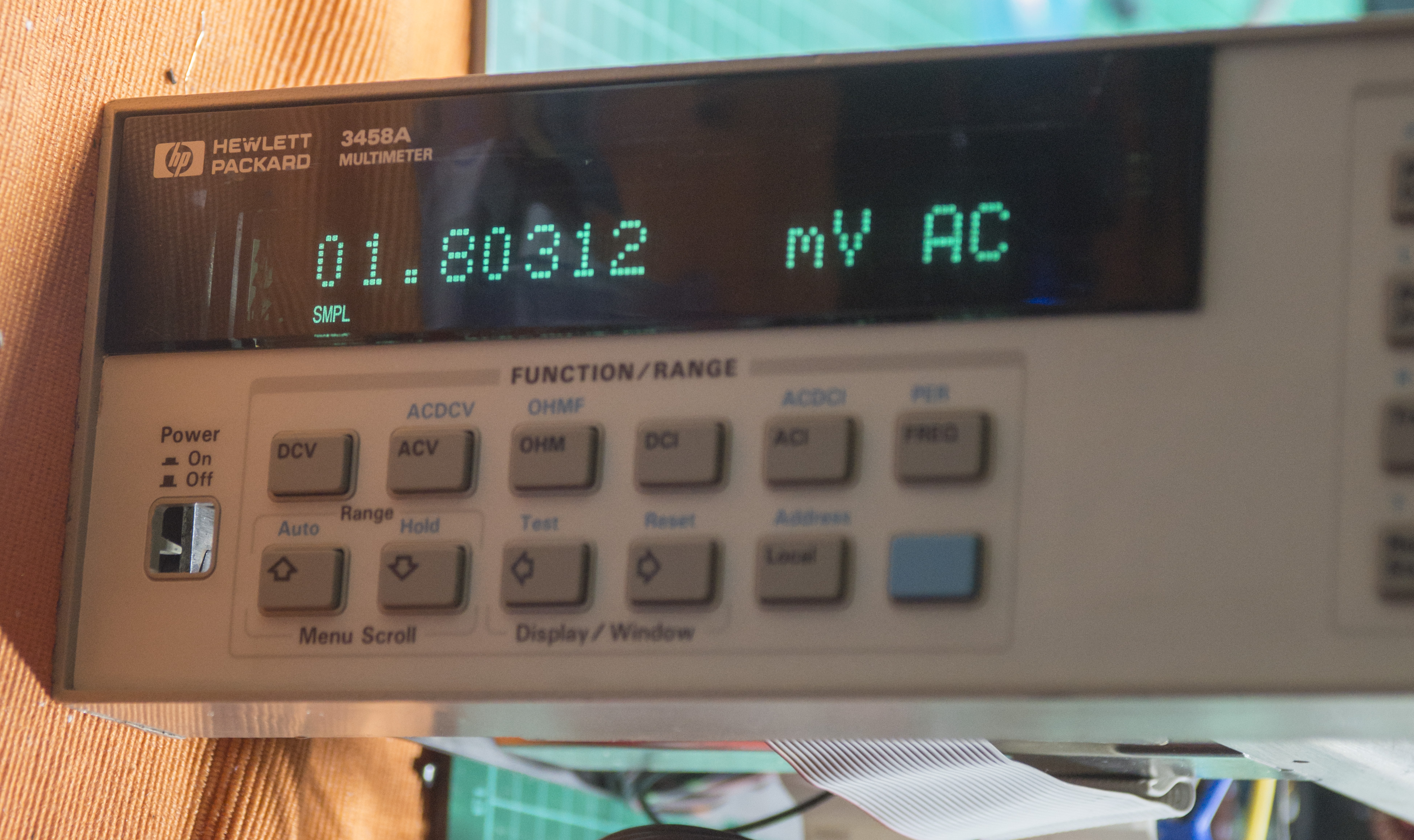

Image 141-144: First boot, and self-test failures
It does light up ERR with next errors:
202,“HARDWARE FAILURE — SLAVE TEST: CONVERGENCE”
110,“CALIBRATION REQUIRED — ACAL”
If I try run ACAL ALL, it says 205,“HARDWARE FAILURE — CAL VALUE OUT OF RANGE: 72” which is DCV A1 value, as per ALRM document.
—-
Update 10/7/2015: Mystery resolved, it was receiver U301 on A3 A/D convertor board which gone bad. After swap receivers with external trigger link, main isolation link working now without any problem.
I will buy new receivers and replace afterwards, but for now external triggering is not critical function and not affect self-test and meter diagnostics.
10.0006 VDC supplied from Keithley 2400, directly to DCV input on A1 PCB.
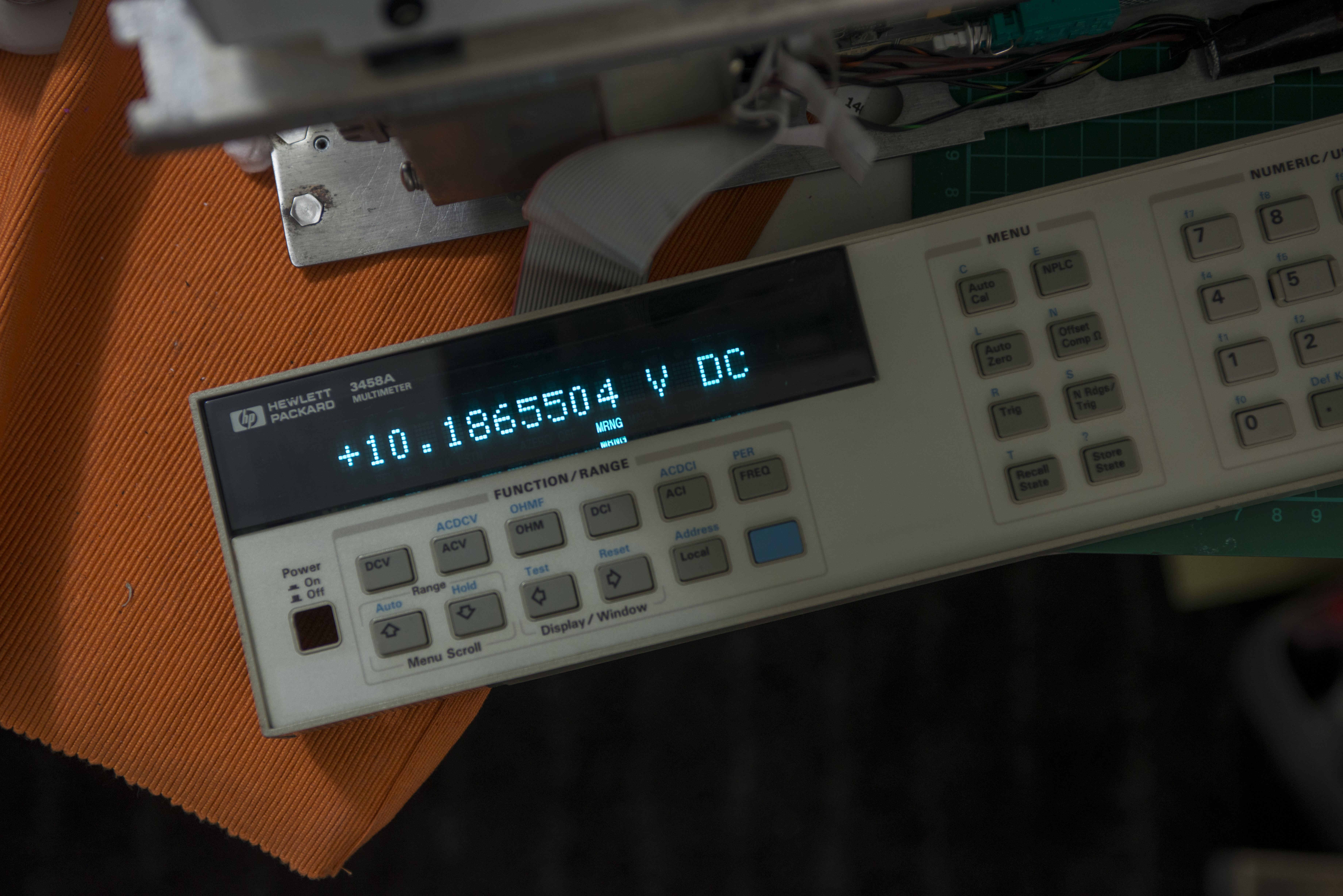

Image 145-146: 10V test
Around 0.5V supplied to input to fit 10K reading, meter in Ohm mode.
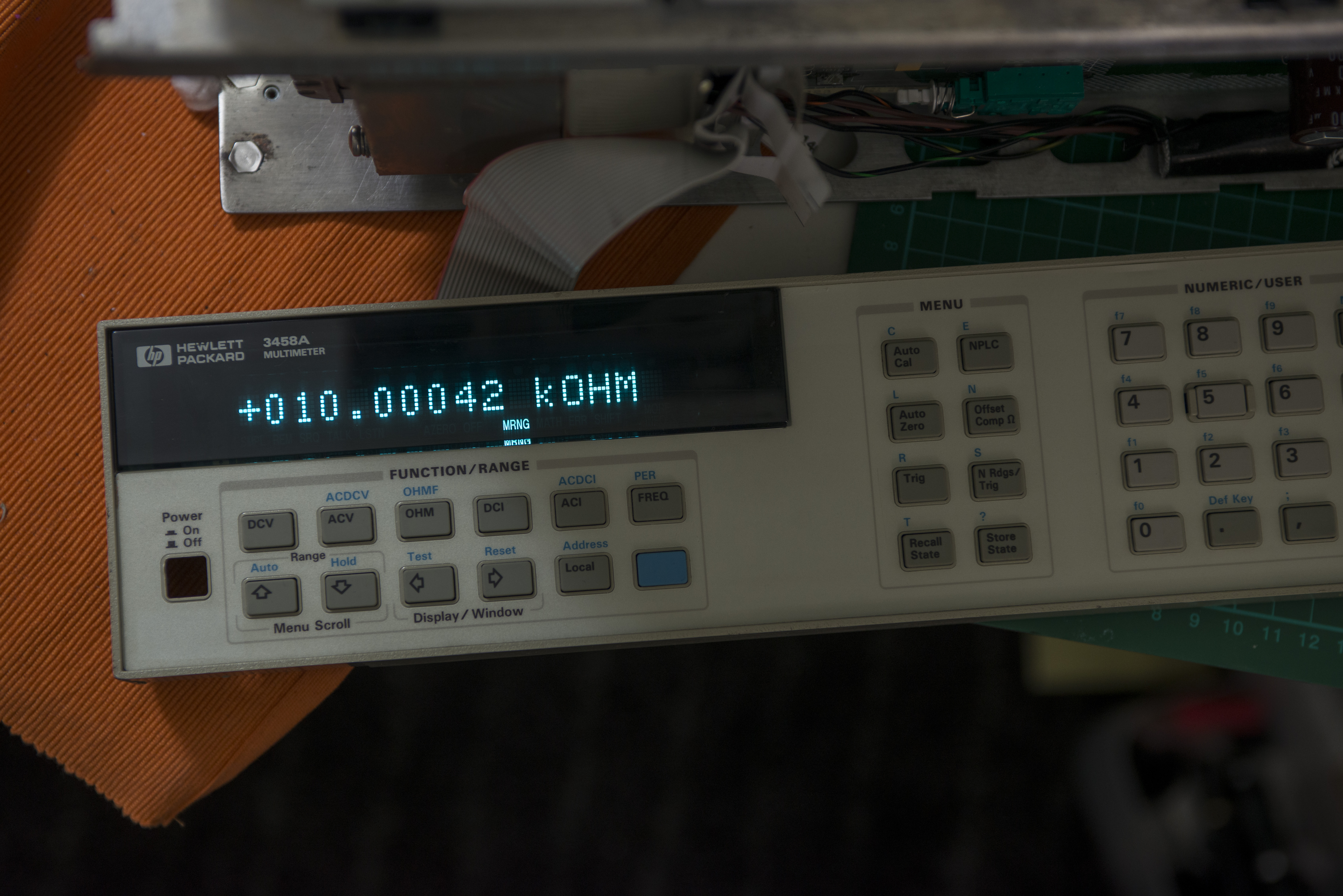

Image 147-148: 10KΩ resistor test
Repair for HARDWARE FAILURE — SLAVE TEST: CONVERGENCE
Issue was simply in missing jumper on A1 DC Board, which selects voltage reference input for rest of circuitry.
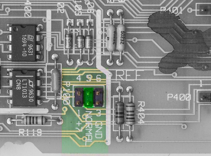
Image 149: Proper A1 PCBA jumper installation for normal operation
After installation jumper on position NORMAL, as marked in green on photo above – this error is gone, as well as meter’s function on DCV,Ohms,ACV,frequency,period were recovered!
Repair for DCI ranges 100nA, 1µA, 10µA, 100µA
Further diagnostics revealed that low current ranges on DCI are not working, reading around zero current, and disregarding actual current on input.
This is also confirmed by failure in self-test and ACAL: 205,“HARDWARE FAILURE — CAL VALUE OUT OF RANGE: 95” which is DCV gain for 10µA value, as per ALRM document.
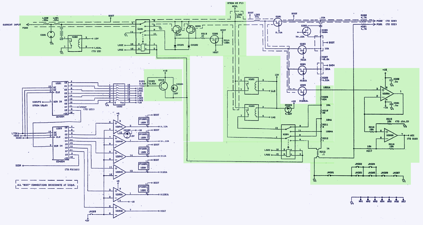
Image 150: Current measurement schematics from CLIP
Since ranges 1mA and more working ok, we can rule out R210,R211,R212,R213 current shunt path, as well as input relays K201,K202,K203.
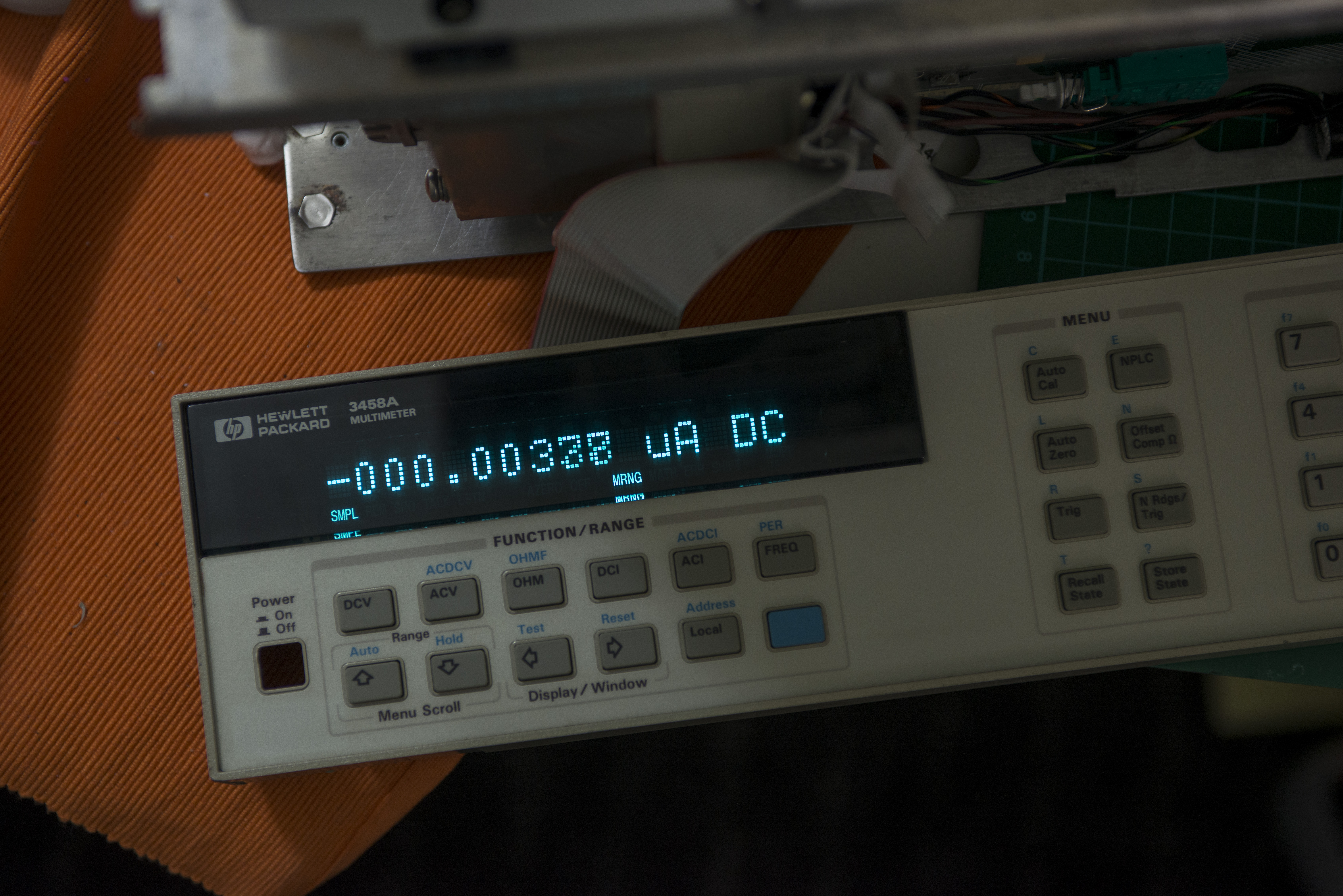
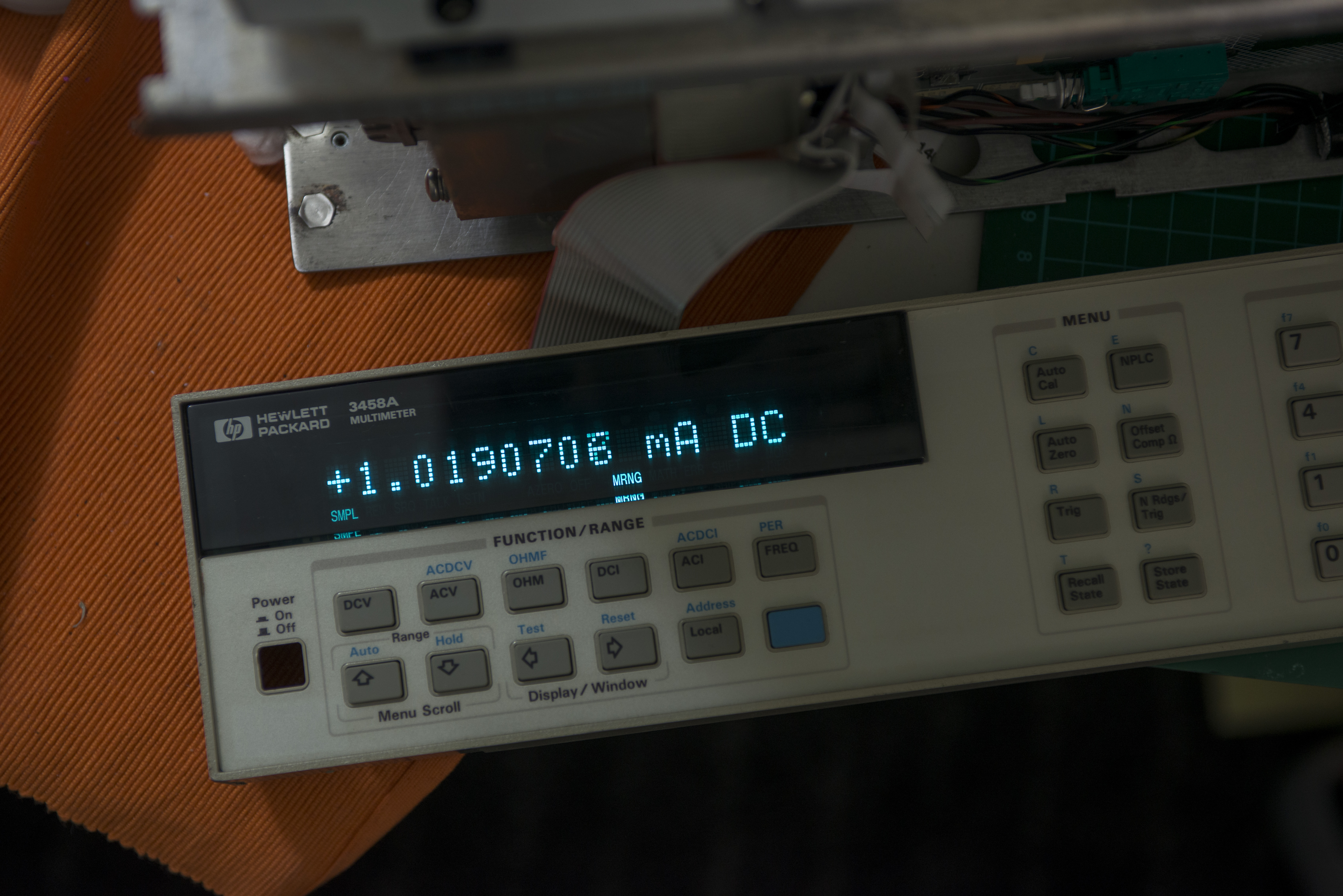

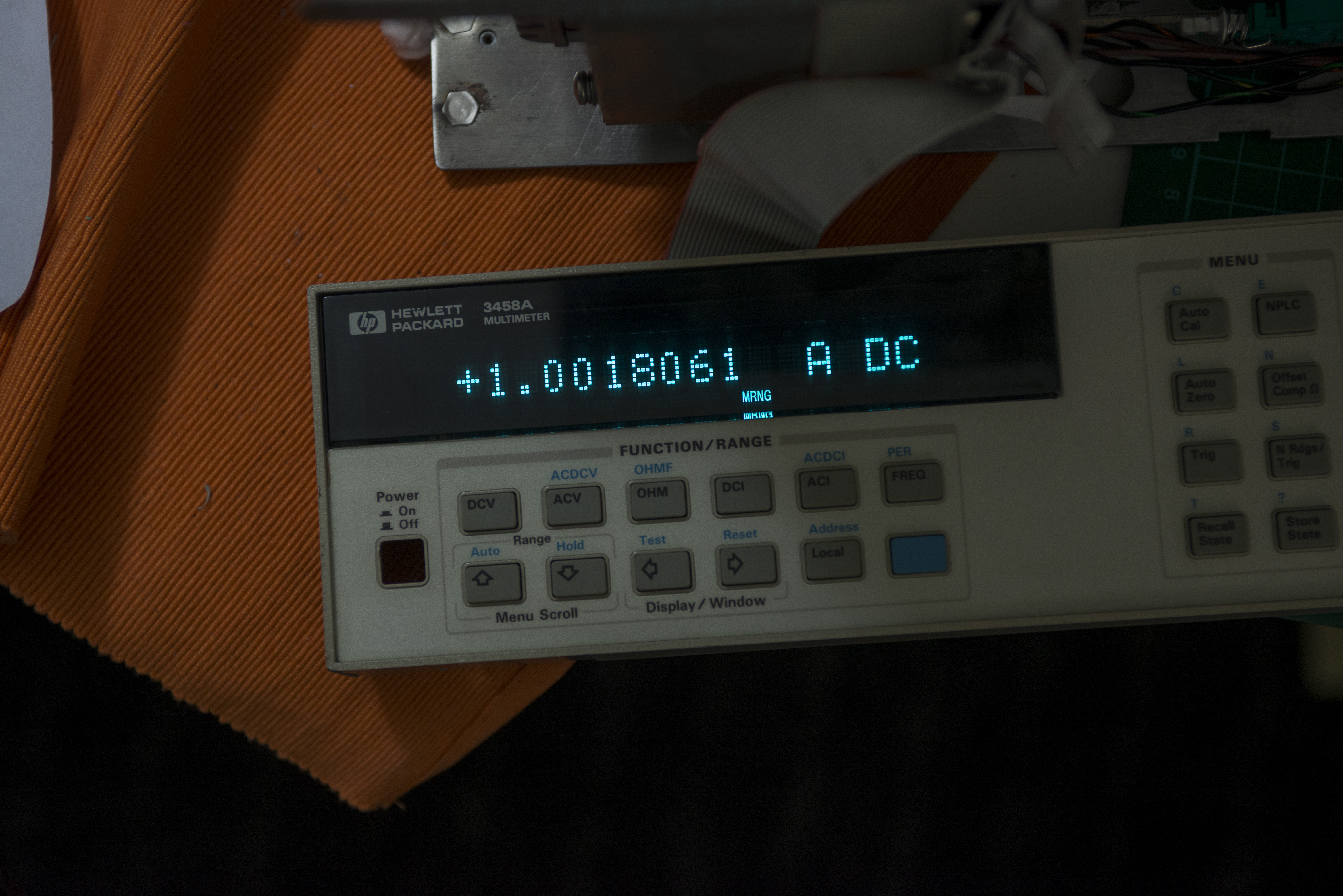
Image 151-154: Current measurement results test
It is not likely that issue to be damaged JFET switches Q201-Q205 for low-current shunts R209-R206, as it’s less probable that all of them died.
So I will test control circuitry first, which consists of U204 and U205 LM339 comparator for level shifting, U203 4094 shift register and RP200 generic resistor network and CR205 zener.
One thing we know from initial inspection – resistor network RP200 was resoldered by previous owner. I have bought RP200 replacement before, just in case, so it could come handy.
Parts summary:
| RefDes | Part type | Digikey ID | Test result |
|---|---|---|---|
| RP200 | Resistor network, 8-SIP 220KΩ x 7pcs | Replaced | |
| U203 | Shift register, serial in, parallel out, 8bit, MC14094BCP | Replaced | |
| U204 | Comparator, LM339N, Selected | OK | |
| U205 | Comparator, LM393N | OK | |
| CR205 | Zener 12V 5% 0.4W, TC ±0.077%, 1N963B | OK |
Table 9: Parts replacement summary
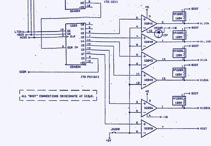
Image 155: DCI control schematics
Something tells us, most difficult in this repair would be finding jellybean LM339 and LM393 in DIP package :). Today modern electronics is using SMT widely to save costs and size.

Image 156: Logic testing for DCI controls
Since I did not have DIP 4094 S/R on hand, I decided to use little bodged SMD adapter just to try if it’s fixes the problem. I’ll order proper DIP-version for final repair later, after confirming solution
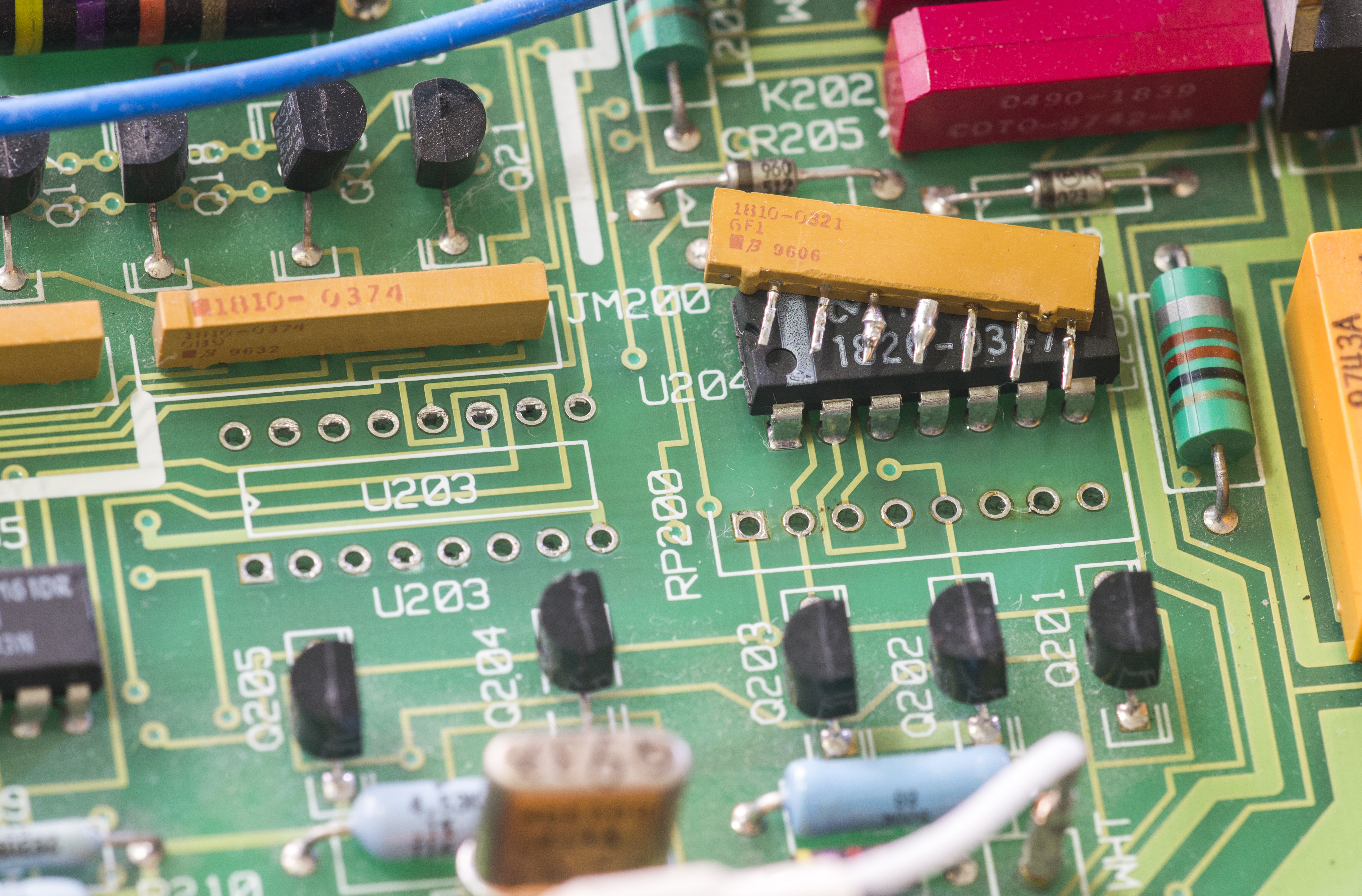
Image 157: Damaged resistor found, before replacement. U203 removed as well
After removal both U203 and RP200, I quickly discovered issue. RP200 missing common pin 1 for resistor array! I don’t know how that happen or what previous owner due to poor resistor. I replaced it with new 220Kohm 7-resistor SIP array. Worth to note, that schematics does show RP200 as pack of 100KΩ resistors, while BOM and actual A1 PCBA have 220K array installed. I used 220K, following original part resistance value.
I quickly made bodge for 4094 U203 :
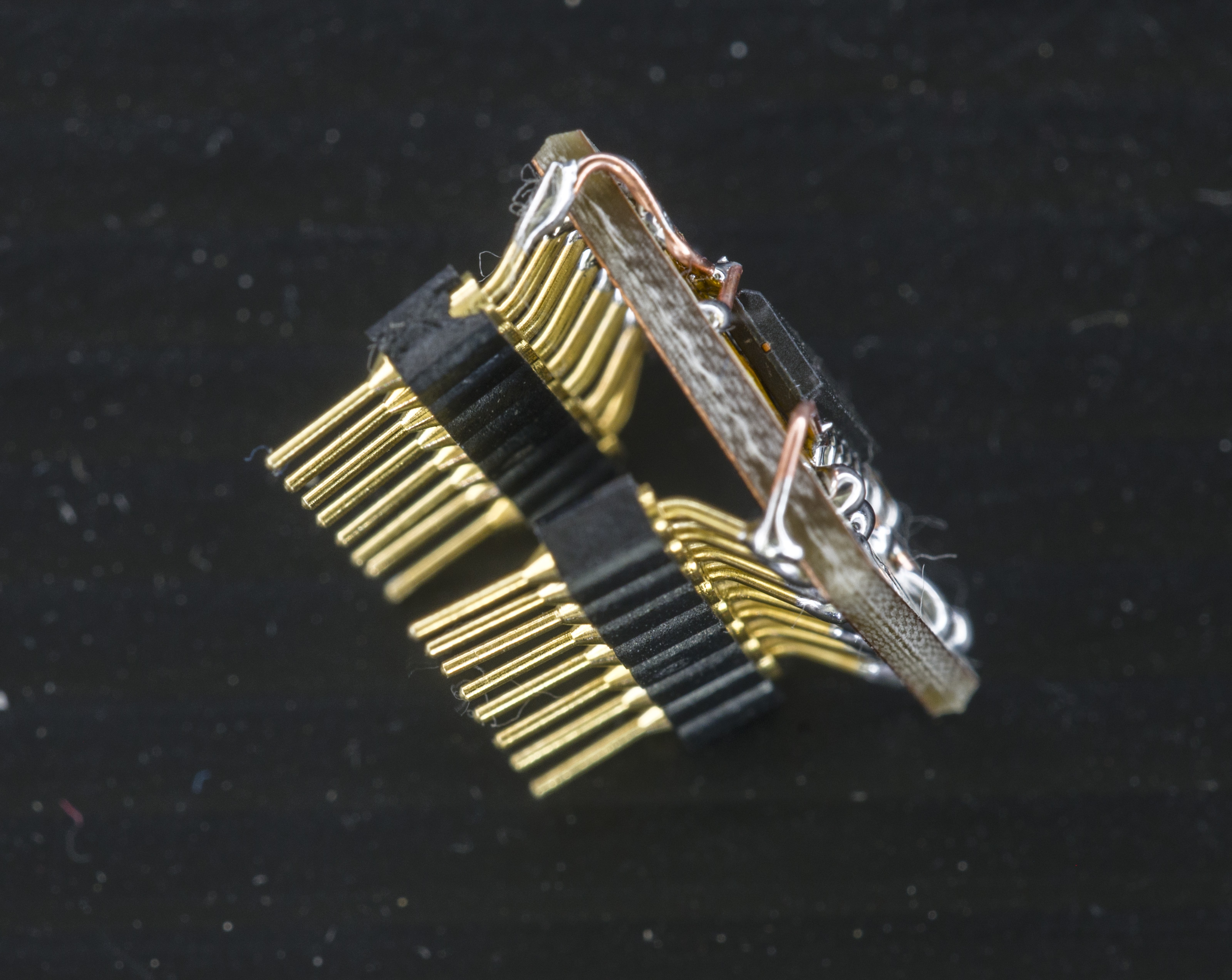
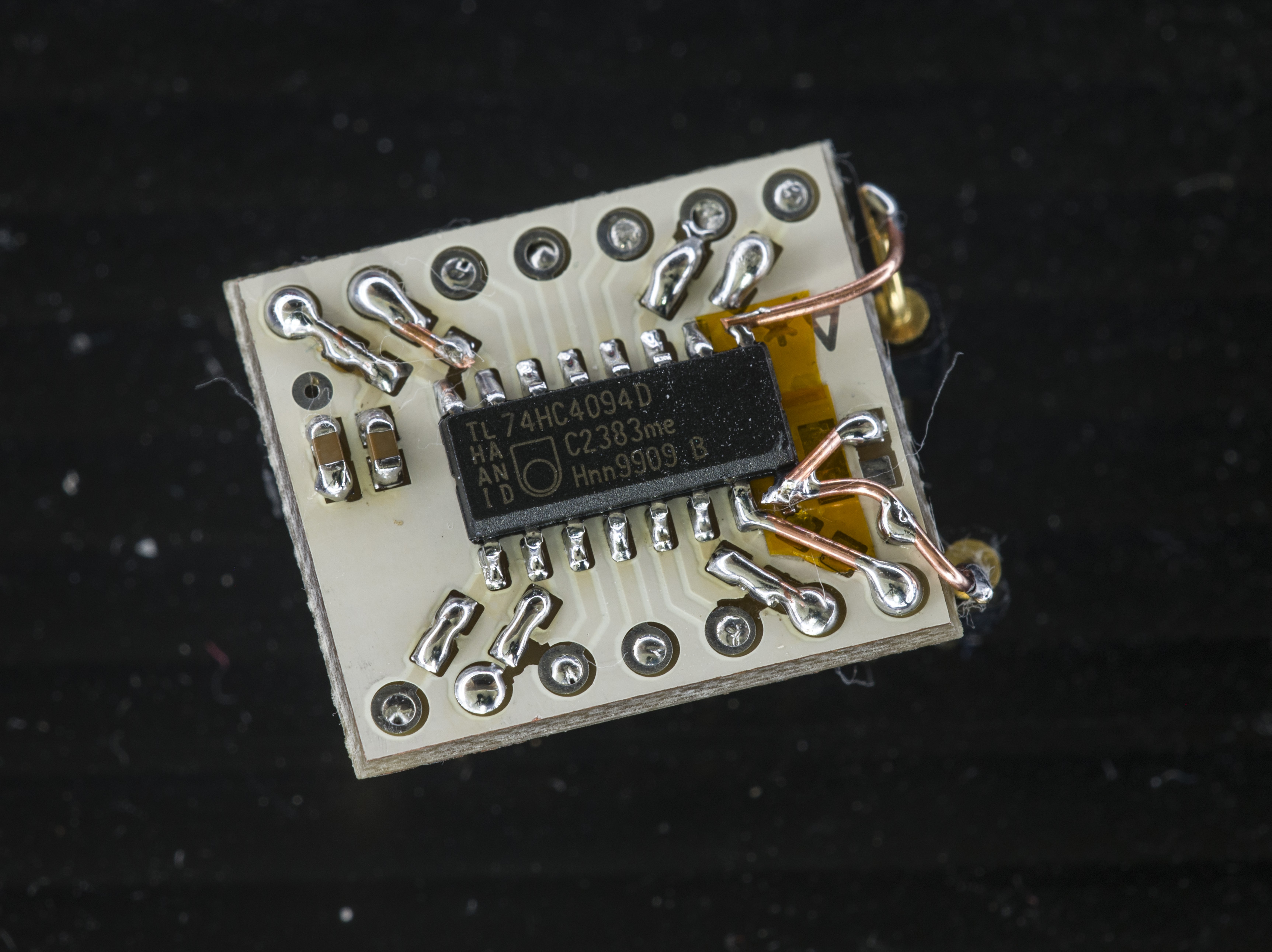
Image 158-159: SMD adapter to quick test U203
Someone would say it’s wrong way to do things, but I was desperate to see unit working..
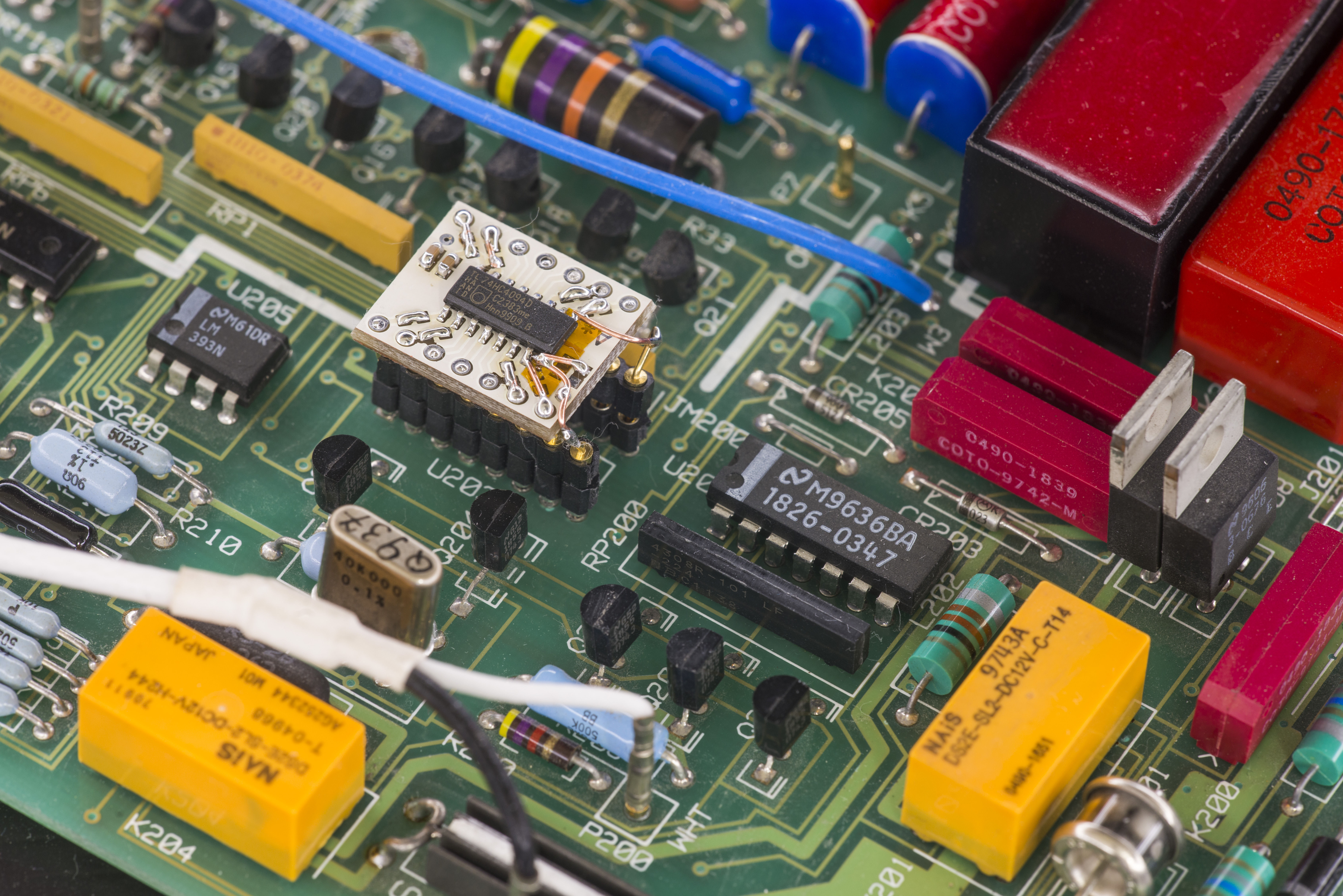
Image 160: Adapter installed in socket and RP200 resistor network replaced
And it did, no problems on low current ranges anymore.
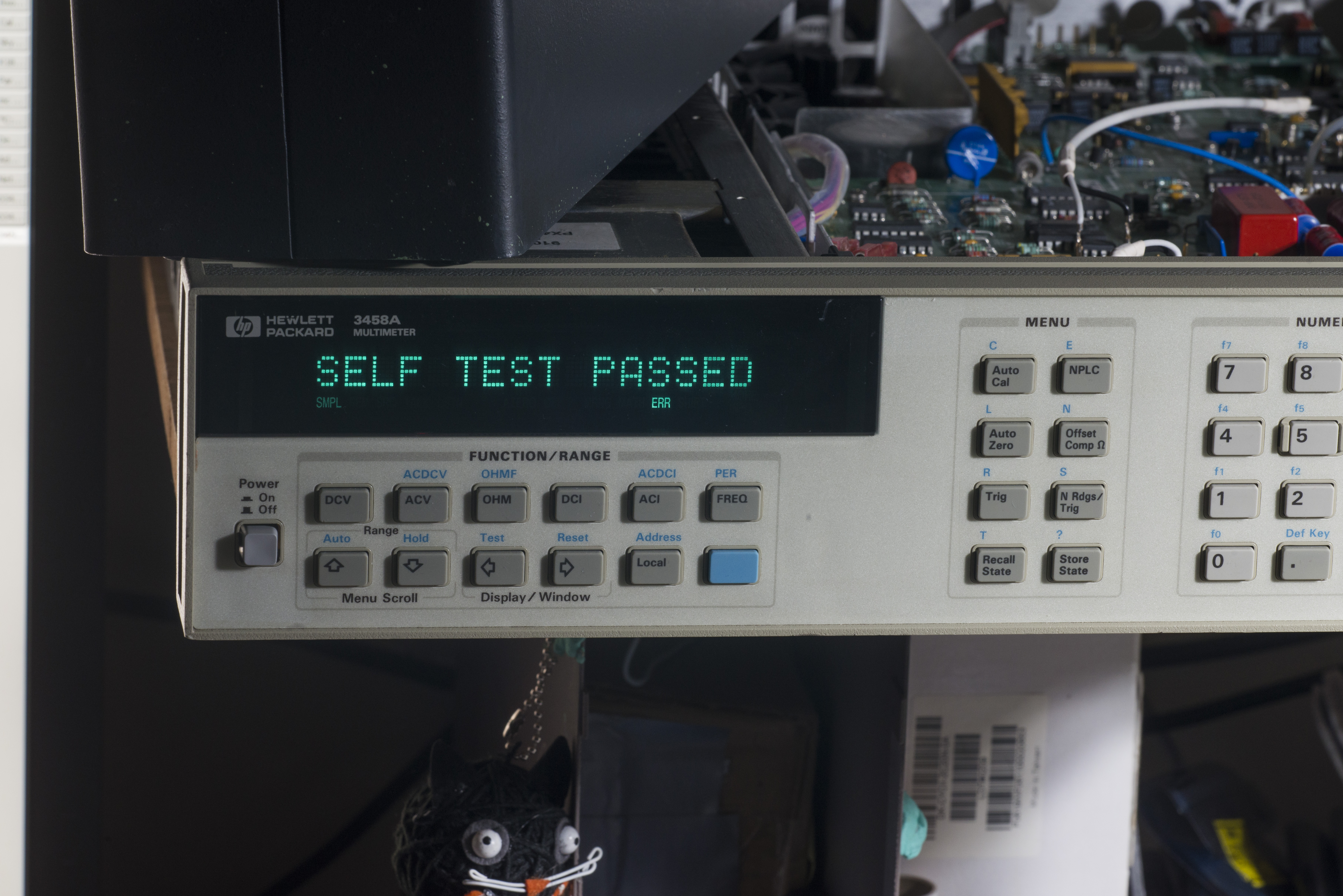
Image 161: First self-test pass!
Unit also does complete whole selftest diagnostics. Very happy to see this SELF TEST PASSED message after all the work we had done above. Now left to do is overall assembly and make sure everything is secured and nice.
I did also ACAL and it passed without problems.
Repair for SYSTEM ERROR — multislope rundown convergence
Well, after that 3458A was running overnight, sampling 10VDC from Keithley 2400. No problems, next morning did couple self-test runs, all pass with flying colors.
Then connected 1Meg resistance from ESI DB52 decade box and left it sampling for about 6 hours. After visit back to check on it, there was ERR lit and measurements halted. Pressing Enter key allow to do few more samples measurements but it halted with ERR within seconds again. New issue.
Checking revealed ERRSTR 114 SYSTEM ERROR — multislope rundown convergence.
It does happen sometimes after a second, sometimes after three seconds on any DCV,DCI,OHM,OHMF functions, and does not occur on ACV,ACI,FREQ,PERIOD or digitize functions.
This error is not listed in repair manual, but there is Service note for Modification to Fix Intermittent Error “Multislope Rundown Conversion” which seem to be related and suggesting nothing else than replacing whole 03458-69503 A3 A/D Converter and Inguard Logic Assembly. This is not an easy option for us, due to involved costs of new A/D board, which is ~$1300USD.
There are few other owners of 3458A who had similar issues with A/D like here’error-209-harware-failure-timeout-unable-to-read-ad’/, here and here and some of solutions suggest replacement of EL2018 comparators, for different issues though.
Some signals waveform captures were made during debug:
U142 EL2018 comparator output to digital domain of ADC:
NPLC 1:
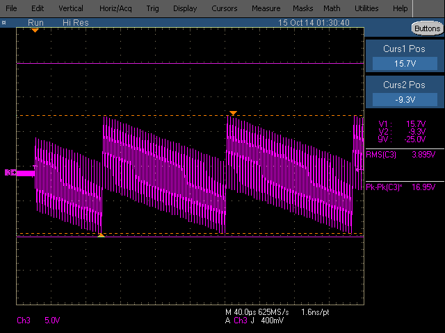
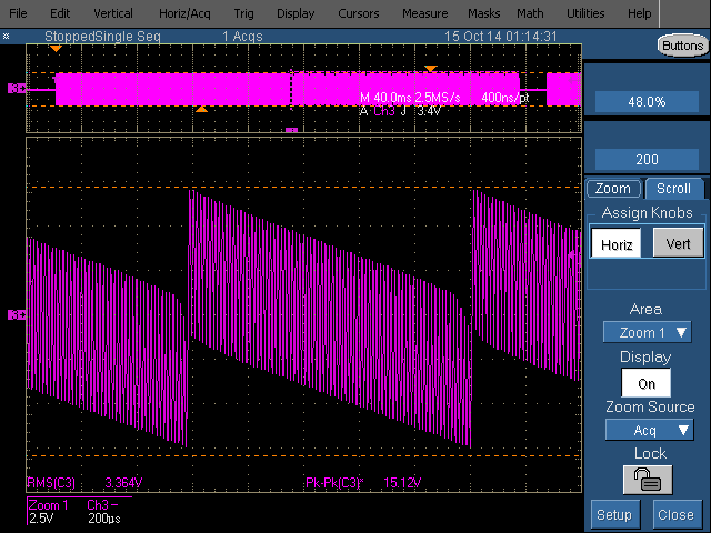
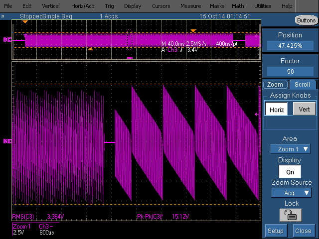
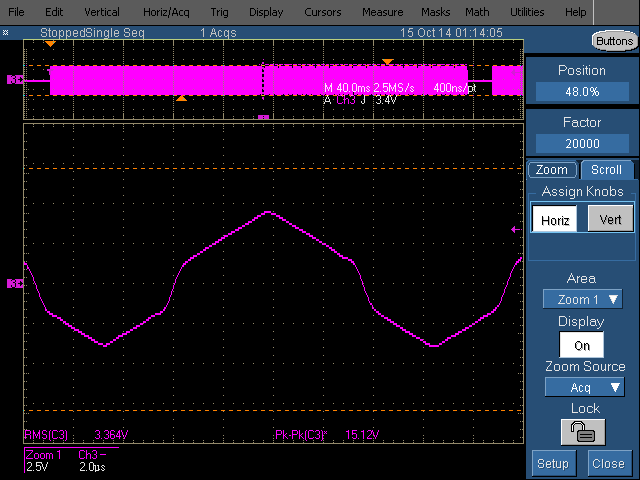
Image 162-165: Various integration settings scope captures
It does seem to be working, at least signal is there. This could also indicate that problem lies in timing/sync, which is more difficult to troubleshoot, as we don’t know correct waveform timings.

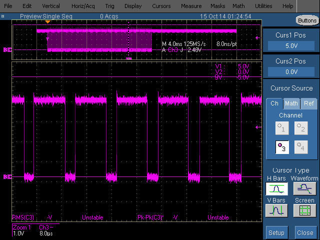
Image 166-167: Integrator and comparator outputs
Above two blocks of pulses, first fast ramps and then slower ramps. Longer pulse train usually have valid measurement displayed on screen.
Sometimes there are only first half of pulses, and also aborted conversion without value shown on screen. Square pulse train waveform is comparator’s output.
A2 Board, U504 buffer (left input pin 2, right output pin 3), meter in mV range on ACV.
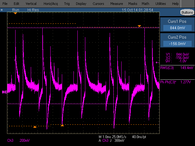
Image 168-169: U504 measurement scope captures
Looking OK, despite U504 running rather warm.
Integrator capacitor waveform (test point TP112, left is NPLC 0.001 failing, right is NPLC 0.0001). Can easy see on faster setting it just takes 2 big ramps to converge voltage, while on slower setting it takes 12 much smaller ramps.
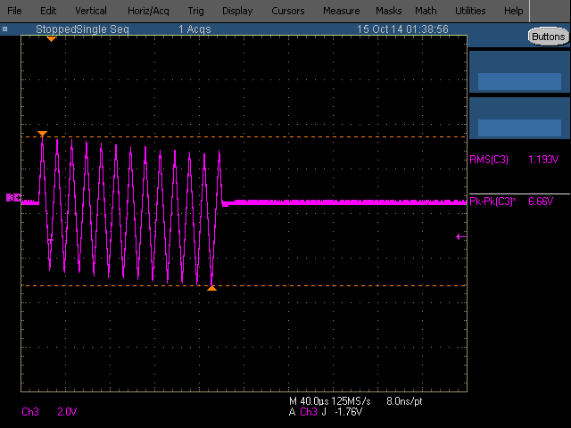
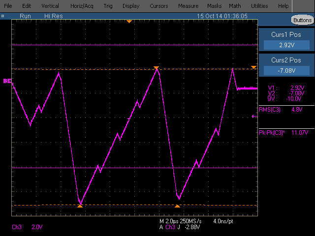
Image 170-171: NPLC 0.001 and 0.0001 settings integrator waveforms
To aid probing and resistance measurement here’s pinout of U180 Hybrid chip (smaller PGA package on A3 PCB).
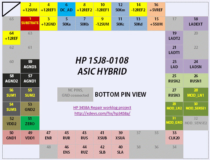
Image 172: U180 ASIC pinout, bottom pin view (at PCB side)
Also there is an error in HP 3458A CLIP, regarding U142 comparator inputs. They are swapped on schematics, so slope amplifier actually connected to non-inverting input of comparator, pin 3.
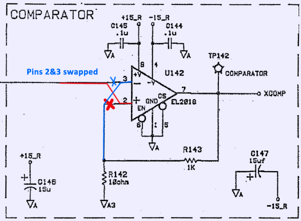
Image 173: Schematics error in CLIP
Up by now I had replaced next parts on A3 PCBA:
| RefDes | Old part | New part | Effect |
|---|---|---|---|
| U142 | EL2018CN | EL2018 | None |
| U181 | EL2018CN | EL2018 | None |
| U405 | EL2018CN | EL2018 | None |
| U170 | LM358 | LT1013CN8 | None |
| U230 | FOX 20.0000MHz 50ppm | XO 20MHz 50ppm | None |
| U301 | Receiver | Receiver | Fixed isolator failure issue |
| U304 | Transmitter | Avago HFBR-1521Z | Fixed isolator failure issue |
Table 11: Replaced parts and their effect on A3 PCBA
This did not help.
So I had no chance but to use plan B, which involved replacement of whole A3 A/D PCBA resolved issue.
Repair for Error 204: Hardware Failure: Level DAC Convergence
This issue is due faulty U501 EL2018 comparator on A2 AC PCBA. After replacement with good EL2018 this issue was resolved.
Video 3: A3 A/D board replacement and test
Now meter running non-stop, to see if we can get any issues.
Repair for A/D drift
This is like never-ending story. After few weeks of testing, I discovered drift issue, caused by A3 A/D board. On DCV function, reading was constantly drifting down on rate ~1.5ppm/hour, independently from temperature variations. Very stable ±2ppm variation over hours, +10.000V DC signal was sourced to input, confirmed by Keithley 2002 and 2001 measurements. Connections, wire, source were kept exactly same in both measurements. Testing of internal 3458A’s voltage reference proven it’s indeed stable (<1ppm at Keithley 2001), and issue is in A3 A/D converter board.
I spent a week, trying different stuff, cleaning A3 PCB, changing integrating C119 330pF capacitor (taken one from old A3 PCB), no any change in behavior.
Then removed U180 analog current steering hybrid chip and decided to swap with U180 from old board, which we had originally with Error 114 convergence issues.
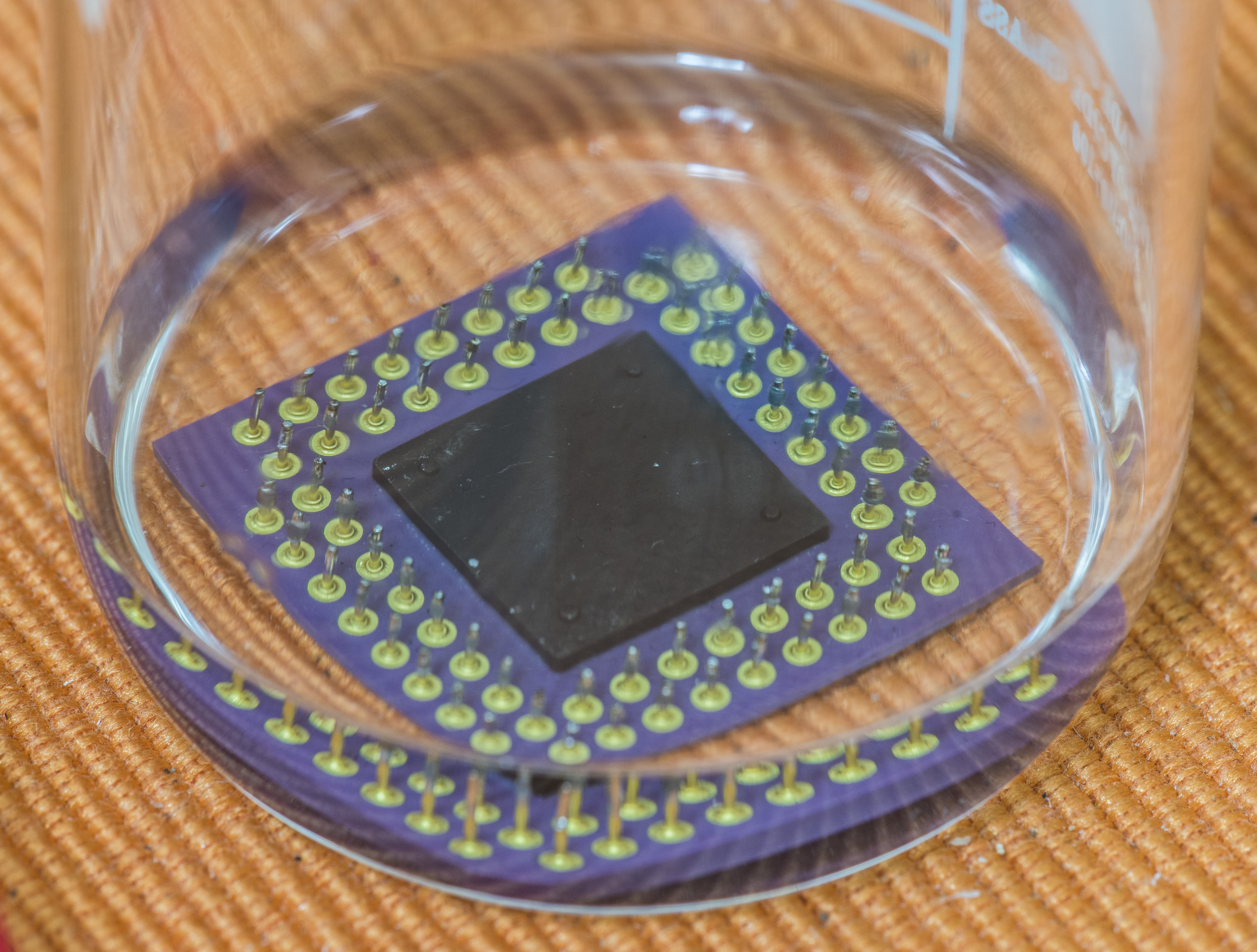
Image 174: U180 ASIC removal and bath in IPA
Here’s money shot, I expect not many HP 3458A owners were brave enough to desolder custom unobtainable A/D ASIC to see it’s bottom side:
Chip on the left is from replacement A3 PCB (it was received from secondary market, not a new one) which have drift issue, chip on the right is from original A3 PCBA.
Image 175: Replaced ASIC
Idea here is test two theories, with swapping this U180 ASIC between boards:
- If old U180 in new A3 PCB will be showing same ERROR 114 convergence issues – root cause for those errors is this ASIC alone. This can be valuable sighting.
- If drifty U180 in old A3 PCB will be showing same drift – it’s ASIC issue again. If not – then some other discrete part on A3 board could cause this drift.
Image 176: U180 hand-writing from new board
Actually, very close examination of drifting chip revealed barely visible pencil handwriting “Drift -1.09” or “Drift = I.09”, which could also indicate previous owner had same issues with this board. When I received PCB it had flux over U180, CR401, R405, R406, U142 comparator. Of course, I cleaned flux prior any soldering, it did not help anything.
So I carefully swapped chips, and here are results.
- New PCB with old U180 got ERROR 114 – balanced multislope convergence right away, so now it’s safe to say – root cause of this is U180 ASIC. If your meter have this problem, prepare for expenses to get replacement A/D board.
- Old PCB with new U180 chip is working without errors, passing self-test, so other parts on this old PCB are fine. It’s rather busted up, as I had multiple components on it replaced without much care (did so, expecting new A3 PCB to fix issues, so not cared that much for old board). As for drift issue, it’s in test right now.
Now we know that drift is isolated to this U180 chip, not the other components on A/D A3 PCBA. What can we do about it, since U180 is custom proprietary ASIC, designed especially for HP 3458A?
Here’s what HP Journal from 1989 about 3458A says about ADC Resistor network:
The resistor network has several requirements. The most stringent is to obtain the lowest ratio tracking temperature coefficient possible. It is important to keep this coefficient low because the gain of the ADC is dependent on the *ratio of the input resistor to the run-up reference slope resistors. An overall temperature coefficient of 0.4ppm/°C was achieved for the ADC. Even at this level, a temperature change of 0.1°C results in a five-count change in a full-scale 8½-digit measurement. (Auto calibration increases the gain stability to greater than 0.15ppm/°C). Another requirement for the resistor network is to have a low enough absolute temperature coefficient that non-linearities are not introduced by the self-heating of the resistors. For example, the 50kΩ input resistor has a input voltage that ranges from +12V to -12V. There is a 2.88 milliwatt power difference between a 0V input and a 12V input. If this power difference causes the resistor to change its value, the result is nonlinearity in the ADC. A 0.01°C temperature change in a resistor that has absolute temperature coefficient of 1ppm/°C causes a one-count error in a 8½-digit measurement. The network used in the HP 3458A’s ADC shows no measurable self-heating non-linearities. The final requirement of the resistor network is that it maintain the ratios of the six slopes throughout the life of HP 3458A. The tightest ratio tolerance is approximately 0.1% and is required to maintain linearity of the high-speed measurements. This is relatively easy requirement. To maintain the ADC’s 8½-digit differential linearity at less than 0.02ppm requires ratio tolerances of only 3%.
I marked important parts in bold. So resistors must have very good temperature coefficient, excellent tracking and match ratio within 3% or better. These parameters are hard to achieve without custom highly-coupled resistor network, but we can give a try, as there is no other choices here at the moment.
ASIC hybrid internals look like this:
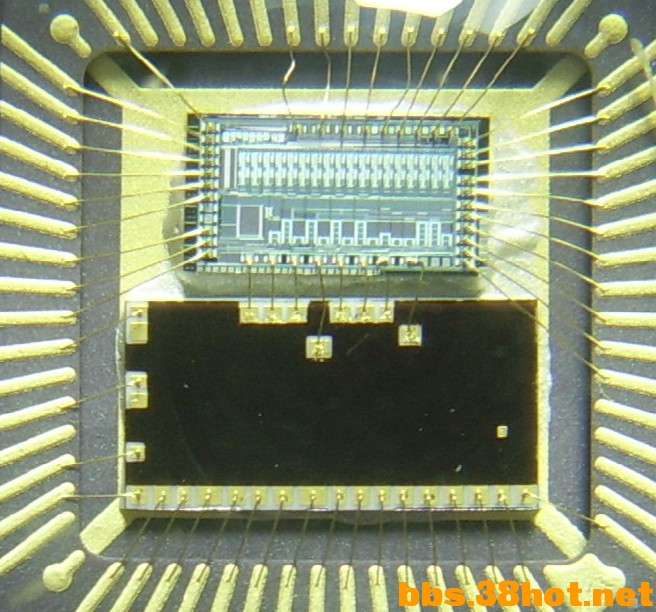
Courtesy: bbs.38hot.net forums
I spent another hundred hours or so replacing various parts, swapping U180 and doing multiple-day long tests, and best I could get was 0.2ppm/hour.
I tried even crazy things, such as shielding A9 voltage reference board with copper foil, but of course that did not help.

Image 177: Copper shield over A9 Reference PCBA
Or replacing resistor networks from Hybrid with external precision wirewound Fluke resistor:

Image 178: DIY resistor network for ASIC Hybrid debug
Since original A9 LTZ1000A from eBay had ~1 ppm random jumps (confirmed by both 3458A readings and external Keithley 2001 at zener output), I opted to replace zener IC to one of old LTZ1000CH from 1990. It fixed jumps, so original LTZ1000A was flaky in the first place. This have nothing to do with ADC issues, just another hidden fault, which is resolved now. Beware, buying at eBay or secondary markets, and if you do – ALWAYS test and check you bought, don’t trust it even if everything looks okay at first glance.
Worth to note, that LTZ1000CH non-A IC warms up much slower than original ACH, this is visible by having 10V on meter and power on from cold state. Voltage creeps 3-4mV/second till it reference voltage stabilize after ~2 minutes. If one try to run selftest during this period, you will be greeted by HARDWARE FAULT 204: REFERENCE CONTROL LOOP FAILURE: 71. Once it warmed up after 20 minutes, both selftest and CAL works OK.
Third ADC PCBA replacement 03458-66503
Since drift issue is isolated to custom U180 Hybrid ASIC, it’s not that much we can do unless to try another board. To get this done, I was given a chance to get A3 PCBA which was tested in another 3458А, to confirm absence of drift/offset errors.
Video 4: A3 A/D board replacement and test
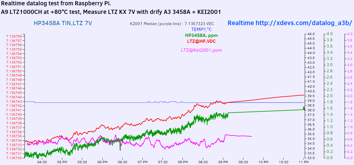
Initial test data available here realtime is good. Hope it will stay that way during next days, to confirm ADC drift issue fix.
Also this issue with ADC drift may not be as rare for many old 3458A meters, as some users might think. One of our readers and supporters, shared realtime CSV-data for his HP 3458A meters, which I plotted on nice graphs here. Data capture at January 7, 2016 on screenshot below:
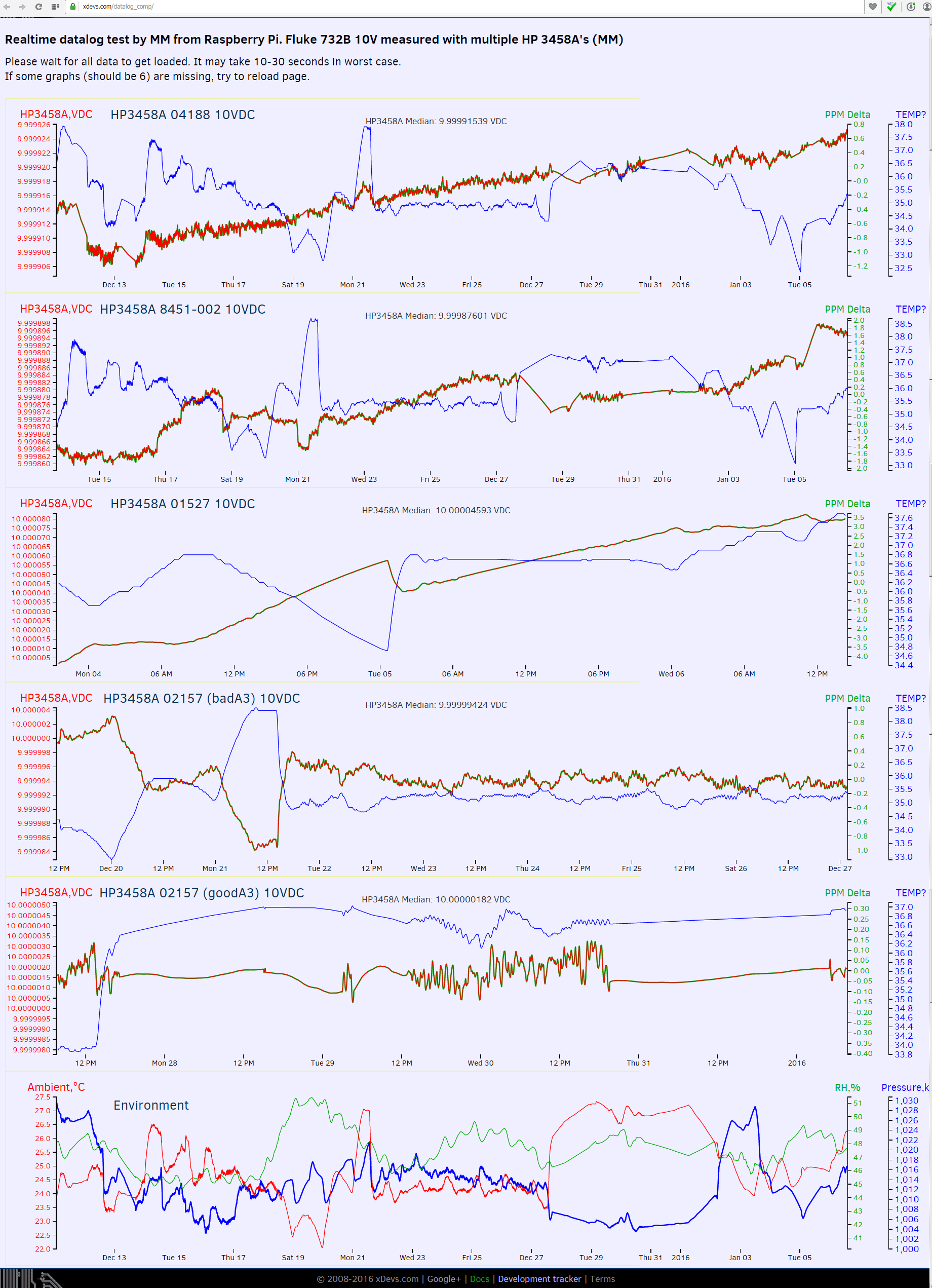
Image 179: Comparison of four HP 3458A DMM’s
This data, up to January 13 for now, allow us to do some basic math, with next result.
- Meter 04188 have drift +0.066ppm/day and tempco +0.066ppm/K. Drifted about +1.3 ppm during 13 days.
- Meter 08451 (with real 002 option) have drift +0.145ppm/day and tempco -0.266ppm/K. Drifted ~*+4.1ppm* during 13 days
- Meter 01527 have drift >2ppm/day. Drifted over +20ppm in 10 days (!)
- Meter 02157 with repaired A3 ADC have drift -0.05ppm/day and tempco -0.266ppm/K
- Meter 02157 with good A3 ADC have very low drift. Note finer ppm scale as well.
Firmware
You can determine firmware revision via the front panel command “Rev?”.
In many cases an old unit might have been retrofitted with newer firmware, so later firmware revision cannot be used as proof of the date of manufacture.
Firmware ROM dumps for HP/Agilent/Keysight 3458A, read by general purpose ROM programmer. From information we have, firmware dumps are compatible with all hardware versions.
| ROM | Revision 2 | Revision 3 | Revision 4.6 | Revision 5.3 | Revision 6 | Revision 7 (1992) | Revision 8 (1998) | Revision 9 (latest) |
|---|---|---|---|---|---|---|---|---|
| U110 | 03458-88820 | 03458-88830 | 03458-88840 | 03458-88850 | 03458-88860 | 03458-88870 | 03458-88880 | 03458-88890 |
| U111 | 03458-88821 | 03458-88831 | 03458-88841 | 03458-88851 | 03458-88861 | 03458-88871 | 03458-88881 | 03458-88891 |
| U112 | 03458-88822 | 03458-88832 | 03458-88842 | 03458-88852 | 03458-88862 | 03458-88872 | 03458-88882 | 03458-88892 |
| U113 | 03458-88823 | 03458-88833 | 03458-88843 | 03458-88853 | 03458-88863 | 03458-88873 | 03458-88883 | 03458-88893 |
| U114 | 03458-88824 | 03458-88834 | 03458-88844 | 03458-88854 | 03458-88864 | 03458-88874 | 03458-88884 | 03458-88894 |
| U115 | 03458-88825 | 03458-88835 | 03458-88845 | 03458-88855 | 03458-88865 | 03458-88875 | 03458-88885 | 03458-88895 |
| 03458-88887 Single ROM | 03458-88897 Single ROM |
Table 12: Firmware ROM dumps
To combine 6 ROM images into single one (for digital board with single 27C4002 EEPROM) this Python app was used.
Based on this discussion Firmware 9.2 is no different in function than 8.2.
I had used UV lamp with little CCFL boost DC-DC (12V powered) supply to erase TMS27C512 UVEPROMs on by A5 board.
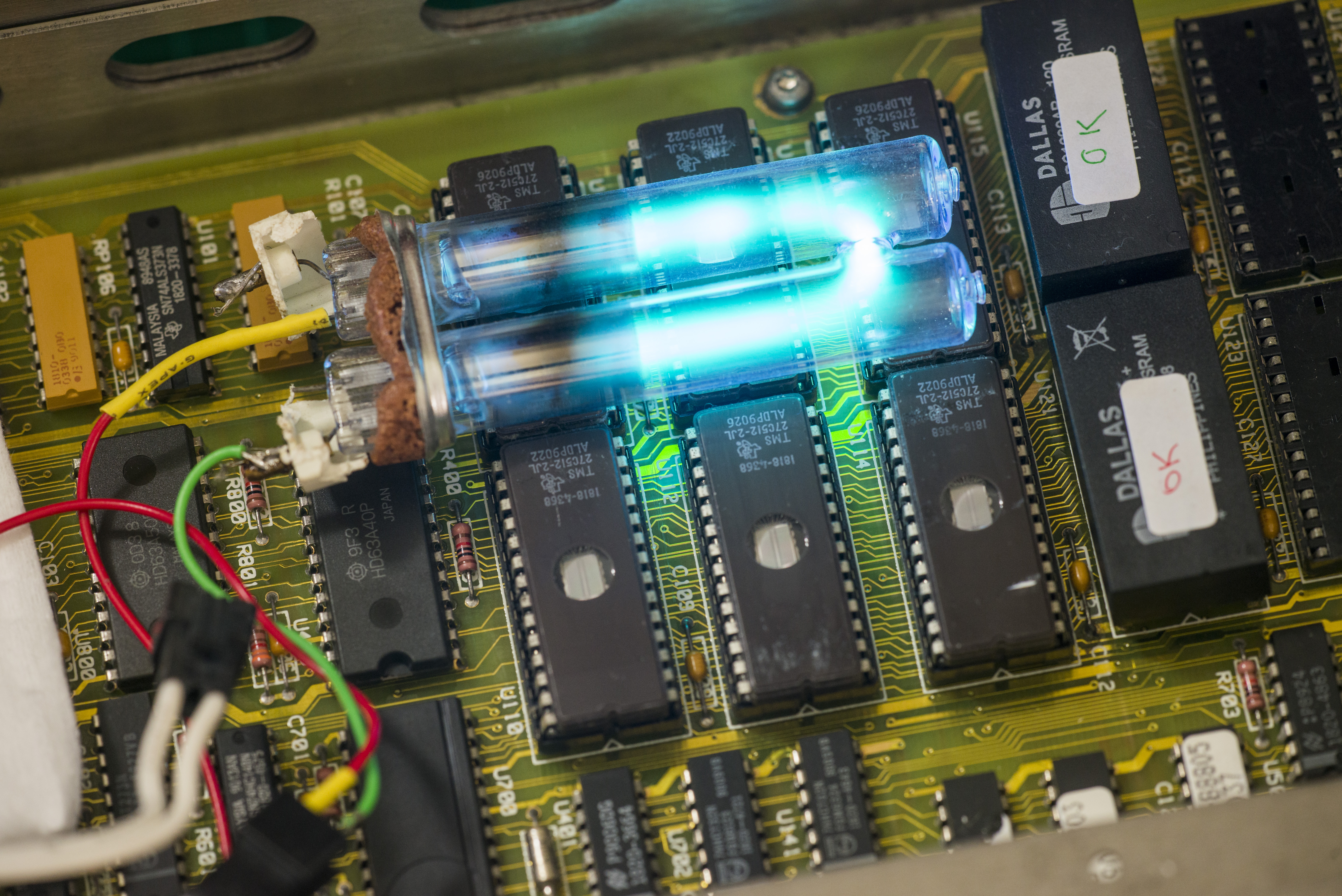
Image 180: DIY ultraviolet lamp erase for ROM upgrade
After 10 minute exposure chips were successfully erased and flashed to REV 9.2 firmware.
Firmware update was successful.
Other possible 3458A issues, reported by community
Here are some common failures reported by other 3458A owners, with provided solutions.
Error 209: Hardware Failure: Timeout – Unable to read A/D
One of users had this issue, discussed in EEVBlog thread’error-209-harware-failure-timeout-unable-to-read-ad’/msg425653/#msg425653
Reason was in faulty U405 EL2018.
Time drift issue for very old 3458A’s
Additionally, if possible run a “Time Drift” test per Service Note 3458A-18 to make sure your A3 A/D board is OK. If the meter fails this test, you’re probably looking at an expensive A3 board repair, or going to follow hard path or debug and expensive repairs like we had to do in drift issue debug section.
Tweaks and tricks
Adding extra memory option
Outguard controller A5 PCB support extra memory option, which is 001 per HP’s classification. Upgrade consisting by installation of extra four 32K * 8 SRAMs into sockets. Access time of 150ns or faster is recommended. Suitable chip example could be HM62256-15 in DIP28 package.
Installation note for 03458-66505 covers this operation in detail. Most important is STEP 6 – apply proper label sticker on upgraded board :)
Newer SMT-version of A5 PCBA have specific installation note covering upgrade to Opt.001. This involve purchase new PAL chip from Keysight, so it’s not free field-upgrade, like with older 03458-66505 A5 board
It’s also easy to check if meter have Option 001 already installed by query OPT? from either GPIB or front panel. If option is installed 1,0 will be displayed:
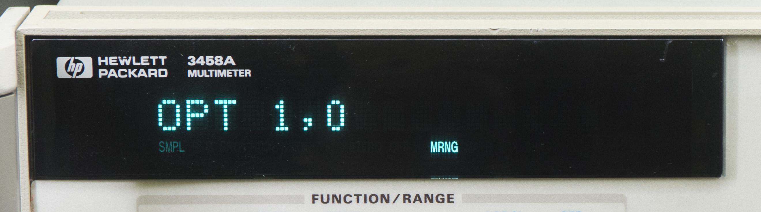
Image 181: Option 001 enabled with extra memory installed
Improving long-term stability of LTZ1000A voltage reference module
Standard 3458A have spec for DCV at 8ppm/year, but there is high-stability option 002 to half this value. If meter used for extended period of times, this could be achieved by simple DIY modification.
It’s useful to tack your voltage reference voltage by reading CAL Variable 2 value from periodically or from calibration to calibration and see how much it is changing (CAL? 2 ENTER). This will only take a few years to get a pretty good idea of how much it drifts, if readings taken with same temperature and environment conditions.
Dr.Frank had performed this and covered in great detail before.
If you change the oven temperature, you will lose the 10V calibration, as the LTZ1000A will change its reference voltage.
STEP 1 – Access reference board A9
- Remove top cover and shield cover on top side of instrument.
- Locate A9 VREF assembly at top right corner (looking at instrument’s face side at bottom)
- Remove A9 VREF carefully. Avoid touching any components with bare fingers, handle on board edges only.
STEP 2 – Change temperature setpoint
- Solder 100K stable resistor in parallel to 15k BMF resistor. Resistor temperature coefficient must be no more than 3ppm/K, better less.
- That gives 13k in total resistance, setting temperature setpoint about 65°C
- An alternative placement is already foreseen on the PCB; in the CLIP, its component designator is X411.
With 100K/65°C, the oven runs about 30°C lower. Therefore, the ambient temperature has to be limited to max. 35°C, the fan has ALWAYS to be kept clean, giving a maximum temperature rise of 15°C, and the instrument may not be put in a rack (which would give additional 10..20°C temperature rise). Under these conditions, (35°C ambient + 15°C 3458A inner heating + 10°C self heating of LTZ1000A + 5°C regulation margin), the oven will always be stable. You can monitor 3458A inner temperature (GPIB command : TEMP?).
STEP 3 – Recalibrate instrument with either ACAL ALL or external calibration
Use known stable and characterized 10V and 10Kohm references to perform calibration. Or perform full calibration with external calibrator.
If instrument planned for service calibration by calibration center, it’s wise to perform this modification prior to sending meter to cal facility.
Here’s how I did it on my A9 PCBA:
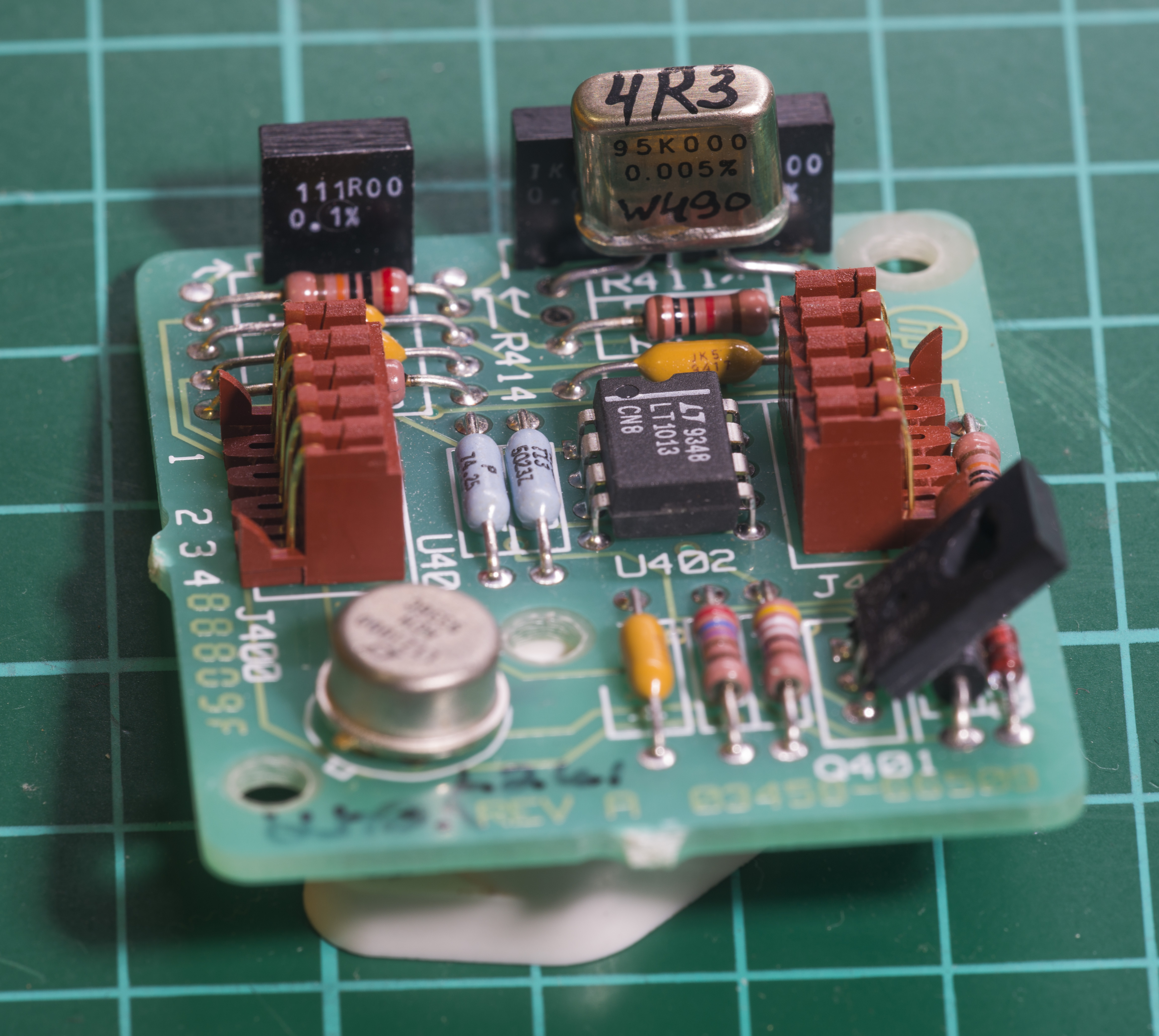
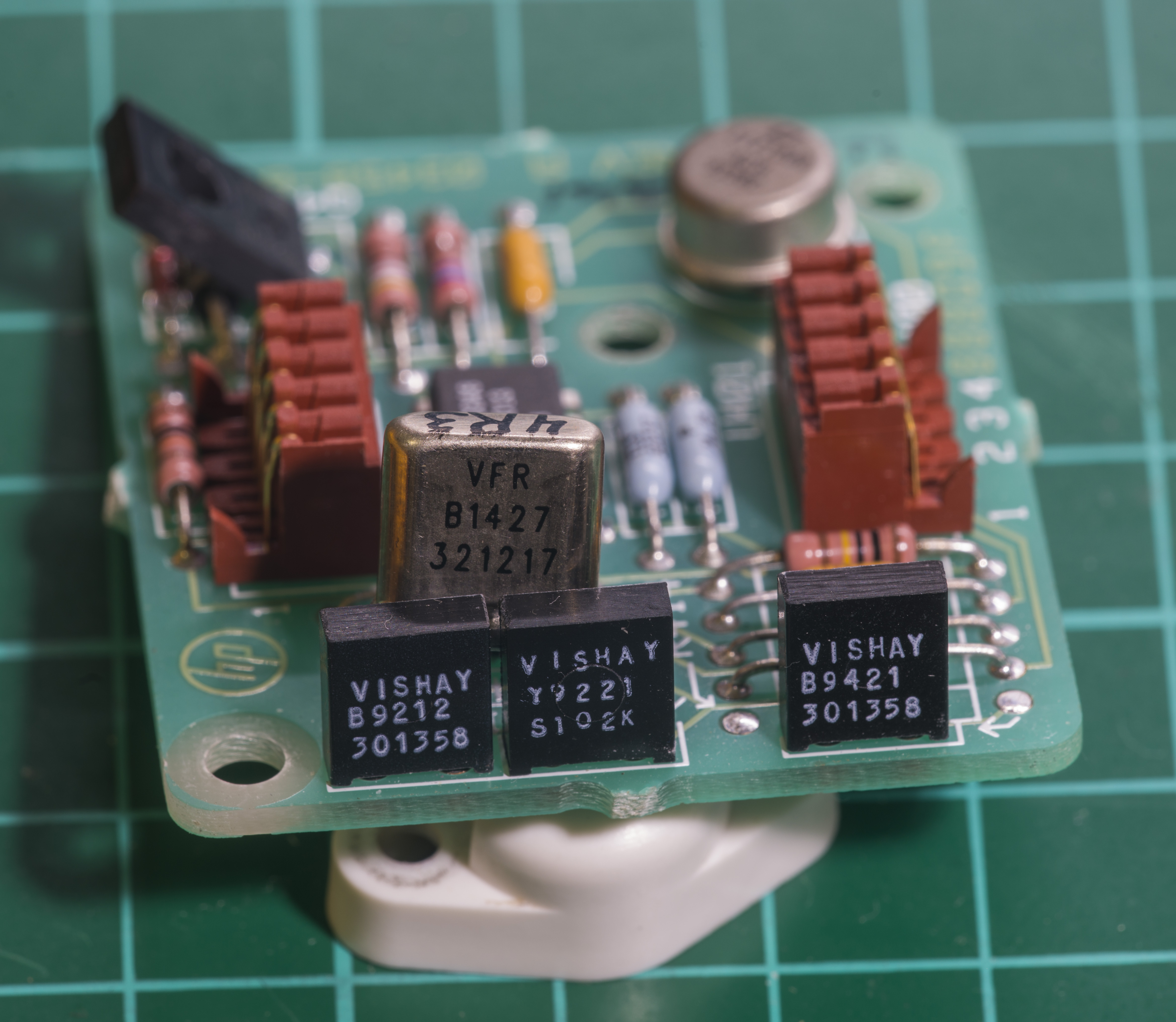
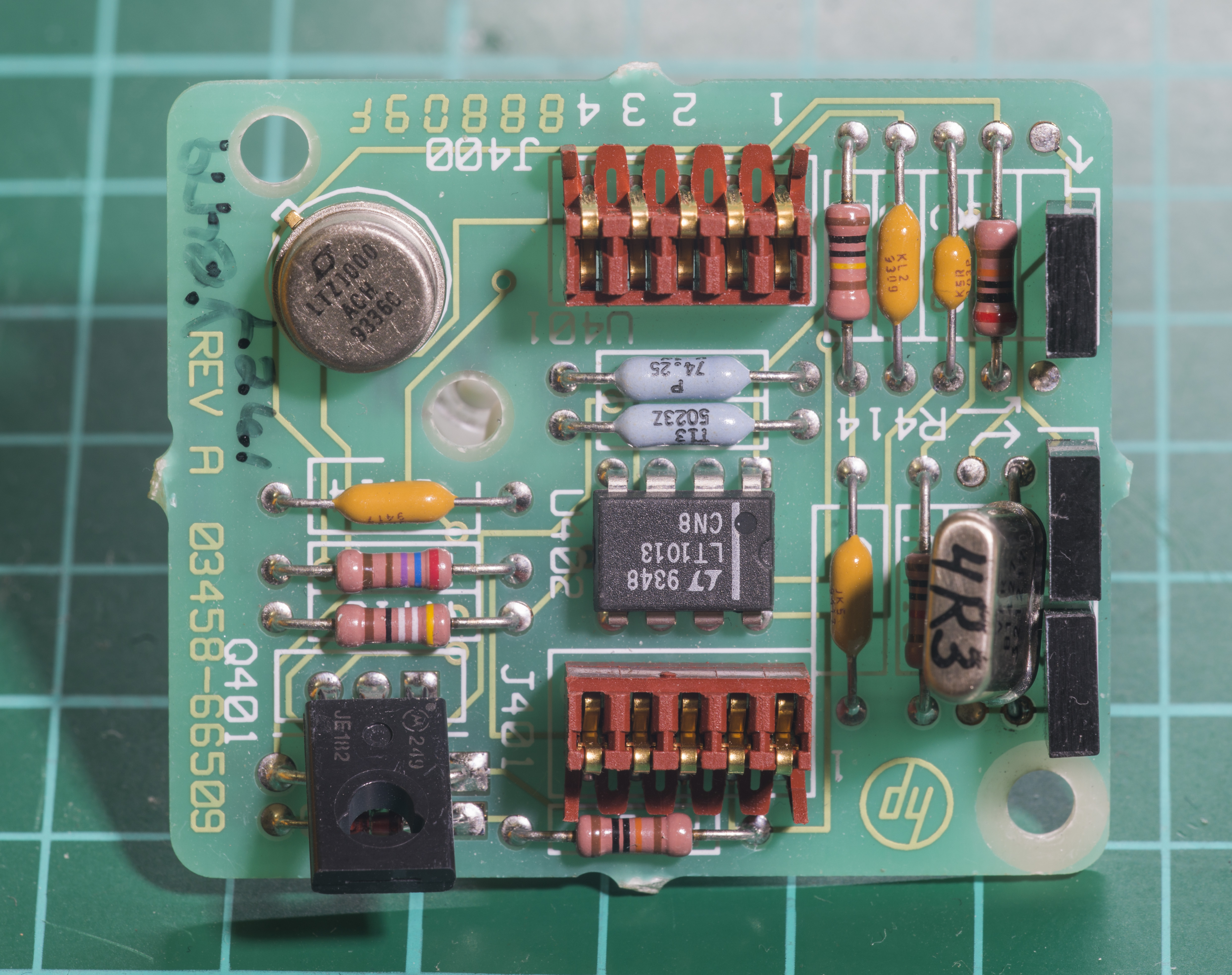
Image 182-184: A9 PCBA modified with Vishay 95K selected foil resistor for lower oven temperature
Used Vishay Precision Group 95.000 KΩ resistor, which is custom-made VHP101 specced 0.3 ppm/°C in +20…+40°C range.
Improving long-term stability for resistance measurement
Most stable resistor in circuit, 40KΩ is currently specified in CLIP’s BOM as ±1.3 ppm/°C. But actual resistor on our board (and any newer 3458A’s as well), is Vishay Precision Group Foil VHP101, in hermetic oil-filled can. This series were released by VPG in 1996, so it’s later change, not reflected in old CLIP. Actual specification for VHP101 shelf-life stability is ± 0.0002% (or 2 ppm) stability in 6 years, and typical TCR ±0.3 ppm/K in +15°C to +45°C window.
Here how older resistor resistor from old A1 PCBA board look like:

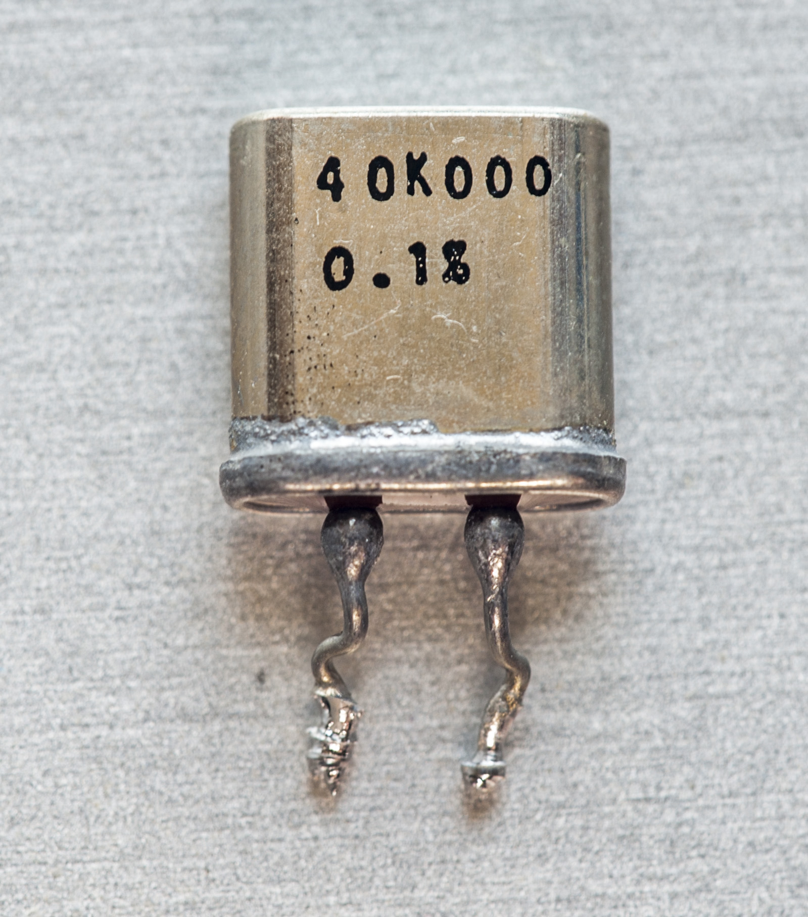
Quick evaluation of this older BMF sample from other’s DMM broken A1 PCBA revealed ~2.7 ppm/K TCR figure.
So finding a replacement for this already ultra-stable resistor would be extremely expensive (hundreds of dollars range, such as VH102Z or VHZ555 with PMO), and is questionable task, as new resistor would need to be aged for few years till it can reach old VHP101 stability.
But other resistors in meter are not so advanced, so replacing one’s used in the Ohm measuring function signal path, with more stable type, like Vishay foils could improve overall stability.
Current resistors used in 3458A’s OHM current source are
| RefDes | Type | Resistance value | TC, ppm/°C |
|---|---|---|---|
| R307 | BMF | 300 Ω | |
| R308 | BMF | 3.00 KΩ | |
| R310 | BMF | 10.00 KΩ | |
| RP300 | Vishay custom array | 30k, 60k, 600k, 6M, 10k, 0.3k, 3k |
Table 13: Resistors spec in OHM/OHMF measurement circuitry
We will study viability of this later, after repair of instrument is complete.
Improving long-term stability for current measurement
VHP101 40K resistor is also part of the DCI/current measurement circuit, which are also could be improved.
Resistors used as current sense elements are
| RefDes | Type | Resistance value | TC, ppm/°C |
|---|---|---|---|
| R206 | BMF | 500 KΩ | 10 |
| R207 | Foil VPG VHP101 | 40.00 KΩ | ±0.3, typical |
| R208 | BMF | 4.53 KΩ | 5 |
| R209 | BMF | 634 Ω | 10 |
| R210 | BMF | 90 Ω | 10 |
| R211 | BMF | 9 Ω | 10 |
| R212 | Custom? | 1 Ω , 2W | 50 |
| R | Custom? | 0.1 Ω | 5 |
Table 14: Resistors spec in DCI,OHM,OHMF measurement path
Disabling VFD to save it’s life during remote operation
Vacuum fluorescent displays are prone to age and lose their brightness with age. This is visible by “burned out” pixels, which are constantly lit. To prevent this happening and prolong display’s life, it’s good idea to turn VFD OFF during remote/long-term operation. Simply send GPIB command DISP OFF plus a blank message text, such as:
DISP OFF,' '
Explanation for this function is in the User Manual, Chapter 6 – Command Reference, about “DISP”, and the last line of the examples contains the crucial hint, p. 171/172.
In Pascal the text string has to be formatted as:
cmd:= 'DISP OFF,'' ''';
Swerleins Algorithm for improved low-frequency ACV measurement
Agilent/Keysight have published method and application example of using HP 3458A to resolve sine AC voltages down to ±10ppm accuracy. This can be used for signals below 1kHz and require external computer to control DMM. Keysight website page have BASIC code examples and datasheet explaining everything in good detail. Information posted there just mirrored on links below:
Visual Basic source code for the High Accuracy AC Measurements with the 3458A
BASIC source code using same algorithm
Other accessory for meter
Rackmount kit is available from vendor under P/N 3458A-909 for $110 USD.
If one to design own plug adapter for front panel binding posts, here are spacing dimensions:
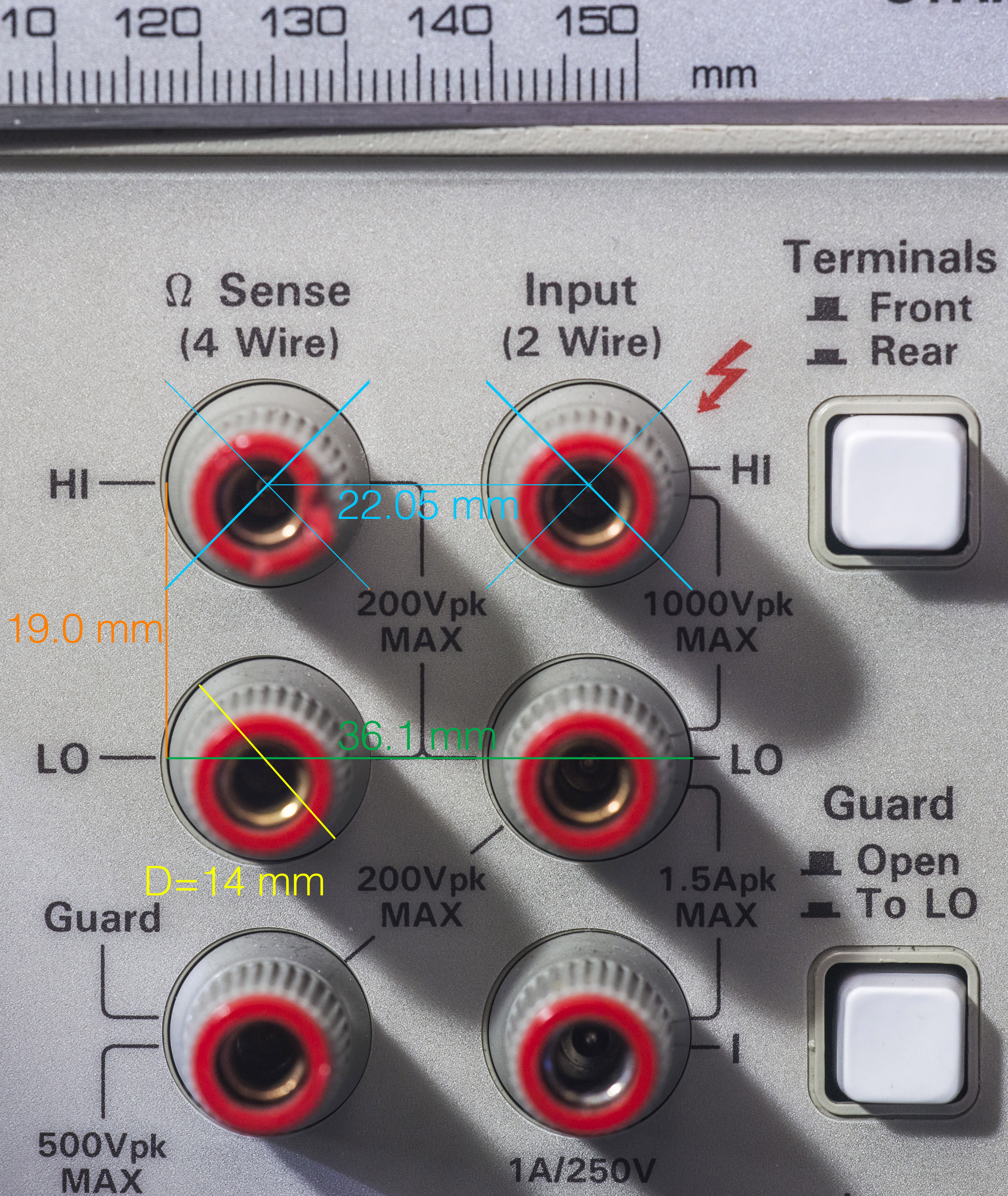
Photo with dimensions is scaled to 1:1 in mm/pixel using custom DPI value.
Calibration
Repair of instrument is one thing, but how do we know if it’s good and meets specifications? Well, we don’t, unless we test known standards/voltages and compare readings from meter to actual values. If reading not match actual value more than specification limits, meter need adjustment. Process of comparison measurements to known value (either it need adjustment or not) is called calibration.
Now, that’s where really difficult part comes. Calibration of let’s say, 4½-digit meter to 10.000 VDC reading is relatively easy, as getting this voltage down to 4th digit is possible without much trouble using shelf parts. Signal must stay constant during whole calibration timeframe (it’s not long, but not seconds either). Also you want to have signal be at least few times more stable, so you will not run on edge during adjustment/calibration. Now, since we want 8 digits, this means we must have stable signal 10.0000000 VDC, down to <100 nanovolts! Also it’s also must be known value. Today’s voltage standard is delivered from quantum standard, JJA, operated at liquid helium temperatures. Very few lab’s have such stable known-value sources, suitable for calibration 8.5-digit instrument like 3458A. Some useful information about calibration procedure can be found here.
Since at this moment I don’t have ability and need to get best calibration for our unit, I’ll just use artifact calibration to 10V/10KΩ sources, measured by Keithley 2001, calibrated in February 2014 by Tektronix Taiwan.
Most of DMMs have own calibration procedures, but in case of 3458A, most of it’s calibration done by two standards, 10 VDC and 10 KΩ.
By measuring of a known external 10V standard, and telling DMM what it should read allow it’s firmware to then change its DC gain scale factor constant to have both readings match that number. Second to that 3458A measures internal main voltage reference, A9 LTZ1000A output to get absolute value of internal 7V. Thanks to high resolution and great linearity of ADC, internal 7V is now can be measured using multiple ranges, to transfer this simple single step calibration internally to all other DCV ranges.
Next time, when meter running artifact calibration (ACAL) without external 10V standard, unit assume that internal 7V from A9 PCBA does not change, and firmware adjusts ACAL DC gain factors to get readings match the stored 7V value.
Very similar approach used to do resistance/current calibration, but using internal 40KΩ Vishay hermetic resistor, located on A1 DCV PCBA. This resistor value is measured by comparing with external known 10KΩ standard and stored in internal calibration memory as reference. Next ACAL meter will read that value and adjust it’s Ohm/DCI gains to match stored resistance.
To do initial calibration, Keithley 2001 (which got calibrated in February 2014 by Tektronix, and is most accurate meter I currently have) used and reference standard. Transfer was done by calibrating EDC MV106 DC voltage standard to read 10.000000 VDC on Keithley 2001 and providing this voltage for 3458A CAL. 10KΩ VPG hermetic resistor acted as resistance standard, measured first by same K2001 in 4W mode.
| Data point | Expected reading | Measured reading before calibration | Measured after | Limit (002 Opt) | Status |
|---|---|---|---|---|---|
| TEMP? | 30-40°C | +38.8°C (ambient +26.9°C) | OK | ||
| Front short 4W | 0 Ω | 0.25211 Ω | -00.00028 Ω | 00.25007 Ω | PASS |
| Rear short 4W | 0 Ω | 0.36664 Ω | -00.00044 Ω | 00.25007 Ω | PASS |
| 4W Ohms 10K | 10.000104 KΩ | 9.999742 KΩ | 10.000136 KΩ | 00.000142 KΩ | PASS |
| +10V | +9.999980 VDC | +10.0008765 VDC | +09.9999819 VDC | 00.0000624 VDC | PASS |
| -10V | -9.999978 VDC | -10.0008699 VDC | -09.9999822 VDC | 00.0000624 VDC | PASS |
| Short 10V | 0 VDC | +00.0000042 VDC | +00.0000002 VDC | 00.0000023 VDC | PASS |
Table 15: Calibration test result
There is a way to read internal voltage and resistance references by issuing next commands:
| Command | Result before cal | Result after cal and A9 tweak | Meaning |
|---|---|---|---|
| CAL? 1,0 | 40.0000000E03 | default value | |
| CAL? 1,1 | 39.9995999E03 | 39.99987145 E03 | actual value = cal value |
| CAL? 1,0 | 40.0800000E03 | max. actual value | |
| CAL? 1,0 | 39.9200000E03 | min. actual value | |
| CAL? 2,0 | 7.20000000E00 | default value | |
| CAL? 2,1 | 7.07422543E00 | 7.06747856 E0 | actual value = cal value |
| CAL? 2,0 | 7.50000000E00 | max. actual value | |
| CAL? 2,0 | 7.00000000E00 | min. actual value |
Table 16: Initial calibration values readout
After ADC replacement and A9 upgrade to LTZ1000CH, here are new constants for CAL?:
| Command | Result before cal | Result after cal and A9 tweak | Meaning |
|---|---|---|---|
| CAL? 1,1 | 39.9995999E03 | 39.9996932 E03 | actual value = cal value |
| CAL? 2,1 | 7.07422543E00 | 7.18075438 E0 | actual value = cal value |
There are also few other “secret” commands, which can be handy for some low-level troubleshooting on 3458A.
| Command | Description | Example result |
|---|---|---|
| CAL? -1 | Samples taken | 22249=NUM_SAMPLES |
| CAL? -2 | Burst 2 length | 543=BURST2 |
| CAL? -3 | Burst 1 length | 931=BURST1 |
| CAL? -4 | Number of readings | 10=NREADINGS |
| CAL? -5 | Sampling speed | 2009=SMPL_RATE |
| CAL? -6 | Sample increment counter | 1=SSMP_INC |
| CAL? -7 | Line period | 3.54039183E-05=PERIOD |
| CAL? 2437 | DEFEAT command issues | 0, DEFEATS valid 2437 |
| CAL? 2941 | Overload events which may violate warranty | 192, DESTRUCTIVE OVERLOADS valid 2941 |
Table 18: Undocumented hidden CAL? query list
Also here’s toolkit to read calibration ROM via GPIB interface:
Windows utility to read CALRAM
Win version, after ACAL DCV,OHMs, decode
Win version, after ACAL DCV,OHMs, binary
ELF-exec for Raspberry Pi Linux version – this one can also read firmware ROM
Linux version, RPI, text decode
Credits go to KE5FX and folks on EEVBlog
There is also GPIB command CALSTR available to store text string after calibration. It’s syntax covered in manual.
CALSTR string[,security_code]
This command store the string in calibration NVRAM, hence it can be write-protected by the calibration security code, if set before. CALSTR? command queue return stored string.
Performance verification
To be done. Measurements with voltage references, foil resistors, ESI decade, frequency, period, currents, temperature, RTD
A/D drift test per Service Note 18
To make sure that short term A/D and meter overall drift is not outside of spec, I followed Service Note 18 test procedure over 10 days, and results shown in table. Meter had ACAL ALL just before reading CAL? 72 variable:
| Date | CAL 72? after ACAL | ppm Deviation | TEMP? | Deviation from day 0, ppm |
|---|---|---|---|---|
| 18 Jan 2016 | 997.711415e-03 A | 0 | 32.5 | 0 |
| 19 Jan 2016 | 997.711486E-03 | +0.0712 | 31.9 | +0.0712 |
| 20 Jan 2016 | 997.711441E-03 | -0.0451 | 33.8 | +0.0261 |
| 21 Jan 2016 | 997.711391E-03 | -0.0501 | 31.5 | -0.0241 |
| 24 Jan 2016 | 997.711709E-03 | +0.3187 | 30.6 | +0.2947 |
| 25 Jan 2016 | 997.711798E-03 | +0.0892 | 31.9 | +0.3839 |
| 26 Jan 2016 | 997.712097E-03 | +0.2997 | 29.9 | +0.6836 |
| 28 Jan 2016 | 997.711577E-03 -0.01 | -0.5212 | 32.3 | +0.1624 |
| 29 Jan 2016 | 997.711566E-03 | -0.0110 | 33.0 | +0.1513 |
| 2 Feb 2016 | 997.711546E-03 | -0.0200 | 32.7 | +0.1313 |
| 3 Feb 2016 | 997.711203E-03 | -0.3438 | 34.6 | -0.2125 |
| 4 Feb 2016 | 997.711465E-03 | +0.2626 | 33.4 | +0.0501 |
| 7 Feb 2016 | 997.712158E-03 | +0.6946 | 35.2 | +0.7447 |
| 8 Feb 2016 | 997.712250E-03 | +0.0922 | 34.8 | +0.8369 |
| 9 Feb 2016 | 997.712179E-03 B | -0.0712 | 36.4 | +0.7658 |
| 10 Feb 2016 | 997.711496E-03 | -0.6846 | 37.6 | +0.0812 |
| 12 Feb 2016 | 997.711259E-03 | -0.2375 | 40.7 | -0.1564 |
| 13 Feb 2016 | 997.711034E-03 | -0.2255 | 42.2 | -0.3819 |
| 14 Feb 2016 | 997.711229E-03 | +0.1954 | 41.1 | -0.1864 |
| 16 Feb 2016 | 997.711666E-03 E | +0.4380 | 36.9 | +0.2516 |
Table 19: SN18 short term drift test
Overall A/D drift rate result per SN18 C = [(A – B) * 1000000] / [A * 22 days] formula = -0.03329 ppm/day, which is well within limits. If this rate is greater than 0.43 ppm/day, then the A3 assembly needs to be replaced, as we learned hard way already during previous second board A/D debug.
If extend data range to 16 February, point E, same C = [(A – B) * 1000000] / [A * 30 days] formula = -0.00839 ppm/day. Monitoring of CAL? 72 variable will continue in future as well, to ensure meter stays is in stable condition.
Repeating of SN18 test after 2 years of meter 24/7 runtime
| Date | CAL 72? after ACAL | ppm Deviation | TEMP? | Deviation from day 0, ppm | CAL1,1? | CAL2,1? |
|---|---|---|---|---|---|---|
| 16 Feb 2016 (Old calibration data) | 997.711666E-03 a | +0.4380 | 36.9 | 39.9996932E3 | 7.18075438 | |
| 08 Jan 2018 (EXT CAL) | 997.705991E-03 | -5.69 ppm | 35.0 | 39.9988613E3 (-20.79 ppm) | 7.18071188 (-5.91 ppm) | |
| 23 Jul 2018 (EXT CAL) | 997.706598E-03 b | -0.61 ppm (New ref) | 34.9 | Day 0 | 39.9988732E3 (+0.30 ppm) | 7.18070929 (-0.36 ppm) |
| 20 Nov 2018 11:20 | 997.706502E-03 | -0.10 ppm | 35.1 | -0.09 ppm | ||
| 20 Nov 2018 11:45 | 997.706455E-03 | -0.05 ppm | 34.7 | -0.14 ppm | ||
| 20 Nov 2018 17:17 | 997.706520E-03 | -0.06 ppm | 34.8 | -0.08 ppm | ||
| 21 Nov 2018 00:03 | 997.706661E-03 | +0.14 ppm | 34.9 | +0.06 ppm | ||
| 22 Nov 2018 22:07 | 997.706213E-03 | -0.44 ppm | 35.2 | -0.39 ppm | ||
| 23 Nov 2018 12:10 | 997.706277E-03 | +0.06 ppm | 34.9 | -0.32 ppm | ||
| 25 Nov 2018 16:10 | 997.706099E-03 | -0.18 ppm | 36.2 | -0.50 ppm | ||
| 30 Nov 2018 18:43 | 997.706205E-03 | +0.11 ppm | 34.6 | -0.39 ppm | ||
| 2 Dec 2018 07:05 | 997.706020E-03 | -0.19 ppm | 36.6 | -0.58 ppm | ||
| 3 Dec 2018 04:00 | 997.706562E-03 | +0.36 ppm | 33.3 | -0.03 ppm | ||
| 3 Dec 2018 19:36 | 997.706480E-03 | -0.08 ppm | 33.2 | -0.12 ppm | ||
| 4 Dec 2018 01:15 | 997.706328E-03 | -0.15 ppm | 33.4 | -0.27 ppm | ||
| 6 Dec 2018 10:17 | 997.706361E-03 | +0.03 ppm | 33.5 | -0.24 ppm | ||
| 11 Dec 2018 23:33 | 997.706521E-03 | +0.16 ppm | 34.9 | -0.08 ppm | ||
| 12 Dec 2018 16:23 | 997.706550E-03 | +0.03 ppm | 35.5 | -0.05 ppm | ||
| 18 Dec 2018 | 997.706348E-03 | -0.20 ppm | 31.9 | -0.26 ppm | ||
| 19 Dec 2018 | 997.706087E-03 | -0.26 ppm | 34.5 | -0.51 ppm | ||
| 21 Dec 2018 | 997.705595E-03 | -0.49 ppm | 39.2 | -1.01 ppm | ||
| 22 Dec 2018 | 997.705990E-03 | +0.40 ppm | 36.8 | -0.61 ppm | ||
| 23 Dec 2018 | 997.706135E-03 | +0.15 ppm | 33.9 | -0.46 ppm | ||
| 27 Dec 2018 | 997.706074E-03 | -0.06 ppm | 34.9 | -0.53 ppm | ||
| 28 Dec 2018 | 997.706157E-03 | +0.08 ppm | 32.9 | -0.44 ppm | ||
| 29 Dec 2018 | 997.706060E-03 | -0.10 ppm | 32.8 | -0.54 ppm | ||
| 30 Dec 2018 | 997.706080E-03 | +0.02 ppm | 33.0 | -0.52 ppm | ||
| 31 Dec 2018 | 997.706323E-03 | +0.24 ppm | 32.9 | -0.28 ppm | ||
| 02 Jan 2019 | 997.705947E-03 | -0.38 ppm | 34.7 | -0.65 ppm | ||
| 08 Jan 2019 | 997.705790E-03 | -0.16 ppm | 36.7 | -0.81 ppm | ||
| 12 Jan 2019 | 997.705930E-03 | +0.14 ppm | 35.7 | -0.67 ppm | ||
| 14 Jan 2019 | 997.705963E-03 | +0.03 ppm | 35.6 | -0.64 ppm | ||
| 15 Jan 2019 | 997.705917E-03 | -0.05 ppm | 35.5 | -0.68 ppm | ||
| 16 Jan 2019 | 997.706075E-03 | +0.16 ppm | 34.7 | -0.52 ppm | ||
| 18 Jan 2019 | 997.705985E-03 | -0.09 ppm | 34.9 | -0.61 ppm | ||
| 21 Jan 2019 | 997.705486E-03 | -0.50 ppm | 35.1 | -1.11 ppm | ||
| 22 Jan 2019 | 997.706073E-03 | +0.59 ppm | 33.4 | -0.53 ppm | ||
| 23 Jan 2019 | 997.705884E-03 | -0.19 ppm | 33.9 | -0.72 ppm | ||
| 24 Jan 2019 | 997.705721E-03 | -0.16 ppm | 34.5 | -0.88 ppm | ||
| 25 Jan 2019 | 997.705712E-03 | -0.01 ppm | 34.5 | -0.89 ppm | ||
| 26 Jan 2019 | 997.705670E-03 | -0.04 ppm | 33.4 | -0.93 ppm | ||
| 28 Jan 2019 | 997.706245E-03 | +0.58 ppm | 34.0 | -0.35 ppm | ||
| 31 Jan 2019 | 997.705847E-03 | -0.40 ppm | 36.3 | -0.75 ppm | ||
| 02 Feb 2019 | 997.705805E-03 | -0.04 ppm | 34.7 | -0.79 ppm | ||
| 19 Feb 2019 | 997.706392E-03 | +0.59 ppm | 36.2 | -0.21 ppm | ||
| 21 Feb 2019 | 997.706497E-03 | +0.11 ppm | 35.1 | -0.10 ppm | ||
| 24 Feb 2019 | 997.706316E-03 | -0.18 ppm | 36.5 | -0.28 ppm | ||
| 25 Feb 2019 | 997.706178E-03 | -0.14 ppm | 34.7 | -0.42 ppm | ||
| 26 Feb 2019 | 997.706415E-03 | +0.24 ppm | 34.8 | -0.18 ppm | ||
| 28 Feb 2019 | 997.705902E-03 | -0.51 ppm | 41.5 | -0.70 ppm | ||
| 01 Mar 2019 | 997.706388E-03 | +0.49 ppm | 36.0 | -0.21 ppm | ||
| 05 Mar 2019 | 997.706301E-03 | -0.09 ppm | 35.9 | -0.30 ppm | ||
| 08 Mar 2019 | 997.706134E-03 | -0.17 ppm | 34.1 | -0.47 ppm | ||
| 09 Mar 2019 | 997.706174E-03 | +0.04 ppm | 34.3 | -0.42 ppm | ||
| 16 Mar 2019 | 997.706253E-03 | +0.08 ppm | 35.5 | -0.35 ppm | ||
| 17 Mar 2019 | 997.705983E-03 | -0.27 ppm | 35.9 | -0.62 ppm | ||
| 18 Mar 2019 | 997.706134E-03 | +0.15 ppm | 36.5 | -0.47 ppm | ||
| 20 Mar 2019 | 997.706242E-03 | +0.11 ppm | 37.0 | -0.36 ppm | ||
| 21 Mar 2019 | 997.706079E-03 | -0.16 ppm | 35.9 | -0.52 ppm |
Table 19b: SN18 short term drift test
Same data presented in graphical format:
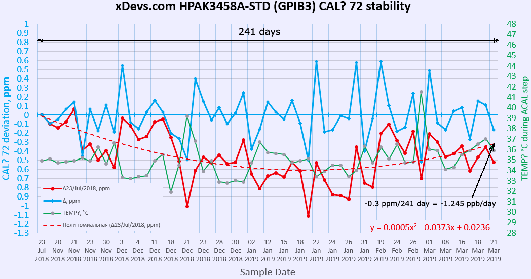
DCV Noise evaluation at shorted inputs
Before we go into capturing samples and data, let’s take a look on DCV specification for noise/speed performance from 3458A’s documentation:
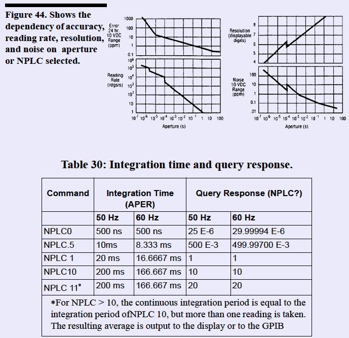
Image 185: Documentation spec for noise
Here is our initial data and comparison to other 3458A from enthusiast, taken as a reference:
| Test | 100mVDC | 1VDC | 10VDC | 100VDC | 1000VDC |
|---|---|---|---|---|---|
| Initial results | Graph 0.1V | Graph 1V | Graph 10V | Graph 100V | Graph 1000V |
| Second ADC board results | Graph 0.1V | Graph 1V | Graph 10V | Graph 100V | Graph 1000V |
| Final 3rd ADC results | Graph 0.1V | Graph 1V | Graph 10V | Graph 100V |
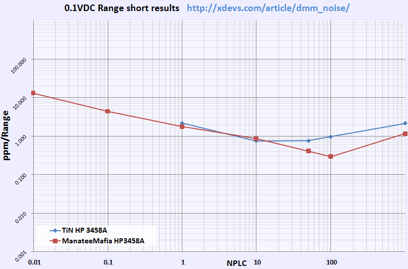
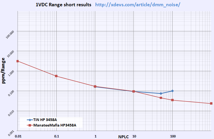
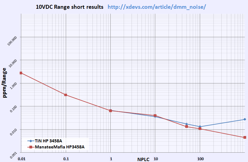
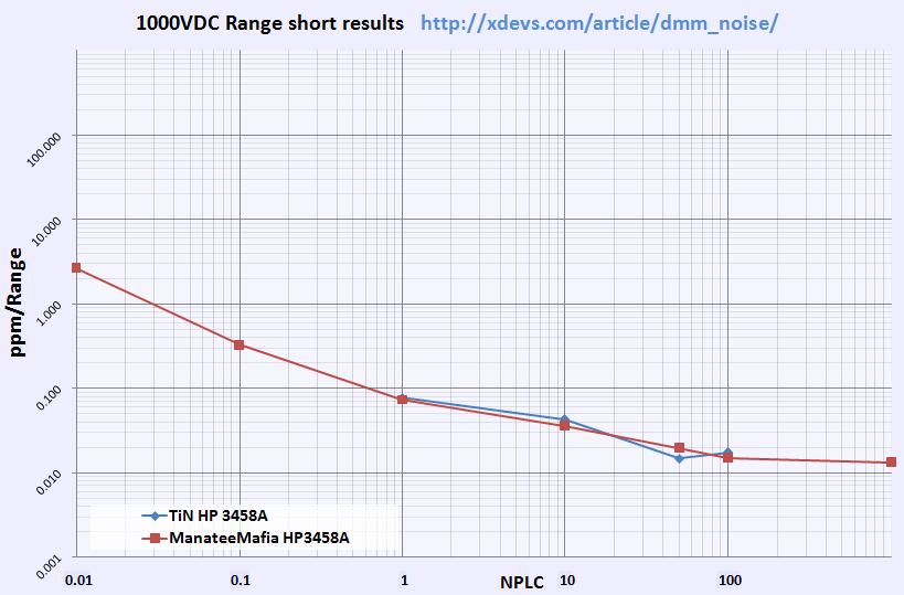
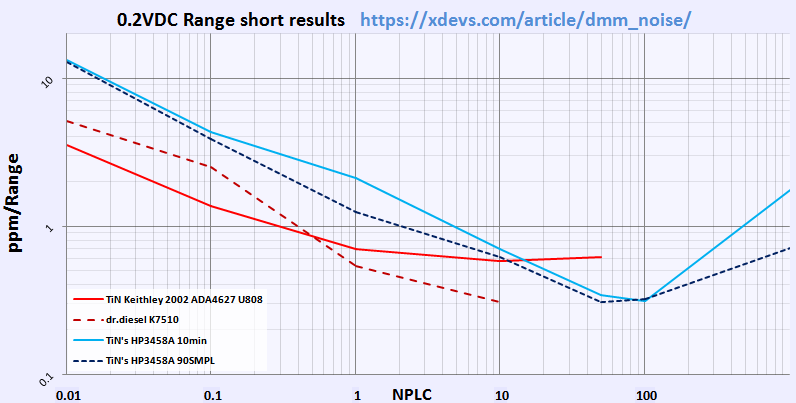
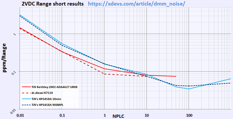
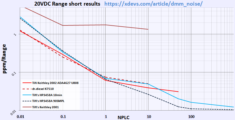
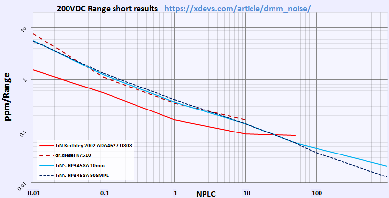
Table 20: Noise at shorted inputs, various tests
Additional test, with LFILTER ON:
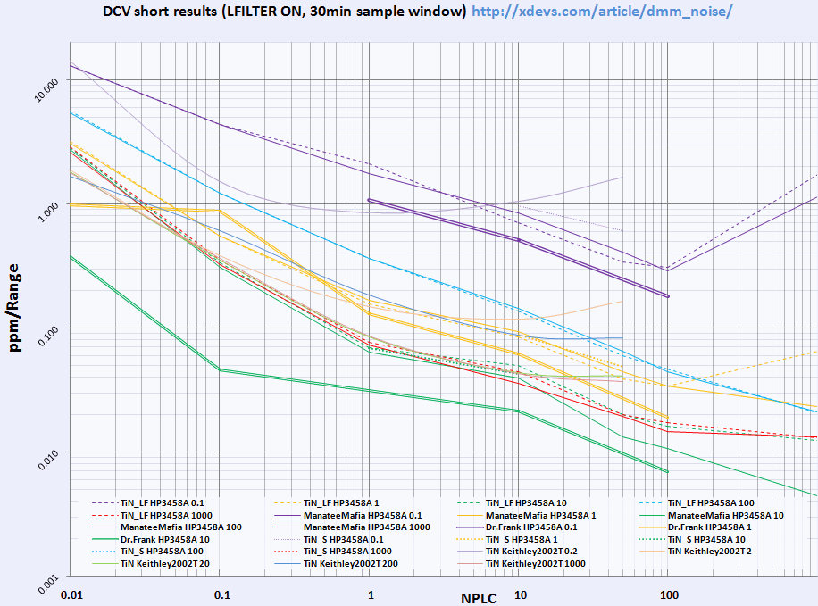
Image 186: Noise evaluation
Remote GPIB control article
HP 3458A instrument is really meant to be remotely controlled via GPIB interface, to use all it’s capabilities. Front panel is not meant for easiest operation, and require decent amount of time invested into programming button scripts and subroutines to perform common tasks quickly.
Separate article to cover usage scenarios with help of GPIB available here
Restoration summary
| Item | Cost | Shipping | Supplier |
|---|---|---|---|
| Dead rusty HP 3458A | 750$ | 190$ | eBay |
| Transformer HP 9100-4715 | 337$ | N/A | Keysight |
| Key cap HP 03458-40214 | 12.12$ | N/a | Keysight |
| Key cap HP 03458-40215 | 12.12$ | n/a | Keysight |
| Pushrod on/off front/rear 03458-43701 | 16.42$ | n/a | Keysight |
| Fuse holder 03458-67912 | 51.63$ | n/a | Keysight |
| Foot 5041-8167 | 46.36$ | n/a | Keysight |
| Shadow switch 3101-2969 (Front/rear) | 55.12$ | n/a | Keysight |
| Tax and shipping | 34.21$ | 73.30$ | Keysight |
| Reference A9 board 03458-66509 | 132.4$ | 9.3$ | eBay |
| 50pcs IN5365B zener | 6.06$ | Free | eBay |
| HP Rear Bezel 03458-47901 | 21.45$ | 26.5$ | eBay |
| DS1220Y-200+ NVRAM | 11.51$ | 7.4$ | eBay |
| 5pcs DS1230Y-200 NVRAM | 22.32$ | 7.06$ | eBay |
| 2nd replacement A3 A/D board, 3458-66503 | Priceless | N/A | N/A |
| 3rd replacement A3 A/D board, 3458-66503 | Priceless | N/A | N/A |
Table 21: Project cost
Also some generic parts were ordered from DigiKey store, such as DC fan, capacitors for A6 board, suspect resistor arrays for logic on DC board and new IEC connector mains filter. Here’s order list (there were some other parts for other projects, not shown here, to make up for >100$ bill, as then it’s eligible for free shipping to Taiwan :).
| Quantity | Part Number | Description | Extended Price USD |
|---|---|---|---|
| 1 | P14736-ND | FAN AXIAL 60×25MM 12VDC WIRE | 9.59 |
| 1 | 565-1846-ND | CAP ALUM 680UF 20% 50V RADIAL | 2.46 |
| 2 | 565-1546-ND | CAP ALUM 220UF 20% 25V RADIAL | 2.85 |
| 10 | 495-6008-ND | CAP ALUM 330UF 20% 35V RADIAL | 7.61 |
| 10 | 1189-2353-ND | CAP ALUM 47UF 20% 63V RADIAL | 3.35 |
| 2 | 493-8635-ND | CAP ALUM 8200UF 20% 35V SNAP | 8.12 |
| 10 | 4308R-1-104-ND | RES ARRAY 7 RES 100K OHM 8SIP | 7.60 |
| 10 | 4308R-1-224LF-ND | RES ARRAY 7 RES 220K OHM 8SIP | 7.60 |
| 1 | 603-1155-ND | FILTER IEC CONNECTOR 115/250VAC | 6.61 |
| 5 | ISL55141IVZ-ND | IC COMP CMOS HS 18V 14-TSSOP | 14.60 |
| 10 | 296-2069-5-ND | IC BUS REGISTER 8STAGE 16-DIP | 4.26 |
| 10 | 296-36143-5-ND | IC HEX INVERTER HEX SCHM 14-DIP | 5.90 |
| 3 | 516-2043-ND | XMITTER FIBER OPTIC 600NM 5MBD | 37.44 |
| 2 | 516-2062-ND | RECEIVER FIBER OPTIC 600NM 5MBD | 24.96 |
| 10 | 568-7933-1-ND | DIODE ZENER 3V 400MW ALF2 | 1.92 |
| 20 | 568-5885-1-ND | DIODE ZENER 12V 500MW ALF2 | 3.66 |
| 3 | 399-4433-ND | CAP CER 2.2UF 50V X7R RADIAL | 9.72 |
Table 22: First Digikey order for parts
Total repair cost in parts as for today: $1312.64 USD
| Date | Activity | Time spent |
|---|---|---|
| 9/15/2015 | Received unit, initial teardown | 1 hour |
| 9/17/2015 | Repair evaluation, testing Outguard boards and PSU, won A9 reference on eBay | 3 hours |
| 9/24/2015 | Replaced C11,CR12 zeners on A4 board, tested board, Keysight parts order shipped | 4 hours |
| 9/26/2015 | Removed DS1220 from A5 board, installed collet socket, installed new DS1220 | 1 hour |
| 9/26/2015 | Ordered caps and new DC fan from DigiKey | 1 hour |
| 9/28/2015 | Cleaning steel chassis from rust, clean front panel | 2 hours |
| 9/29/2015 | Cleaning outside instrument covers, inner frame steel bar | 2 hours |
| 10/1/2015 | Received A9 VREF PCBA, tested standalone with Keithley SMU+DMM | 2 hours |
| 10/4/2015 | Replaced GPIB connector on A5, removed caps on A6, finished chassis cleaning | 3 hours |
| 10/5/2015 | Received parts, bought few more capacitors | 2 hours |
| 10/6/2015 | Test assemble unit, debug ISOLATOR FAILURE error | 8 hours |
| 10/7/2015 | Capture logic diagrams around A5.U700, narrow down isolator failure on A3 PCBA | 4 hours |
| 10/8/2015 | Fixed optical link, got first measurements out of unit | 6 hours |
| 10/10/2015 | Debug attempts on A3 board for 114 convergence error | 3 hours |
| 10/11/2015 | Debug attempts on A3 board for 114 convergence error | 12 hours |
| 10/14/2015 | Debug attempts on A3 board for 114 convergence error | 6 hours |
| 10/18/2015 | Debug attempts on for 114 convergence error | 6 hours |
| 10/20/2015 | Debug attempts for multislope convergence error, measurements on A1 | 5 hours |
| 10/24/2015 | Debug attempts for multislope convergence error, measurements on A3 | 6 hours |
| 11/4/2015 | Replaced A3 A/D board, Error 114 fixed | 0.5 hours |
| 11/4/2015 | Error LEVEL DAC CONVERGENCE fixed by U504 replacement | 0.5 hours |
| 11/21/2015 | A/D U180 drift -1ppm/hour debug | 30 hours |
| 11/29/2015 | A/D U180 drift debug, resistor network replacements | 16 hours |
| December 2015 | A/D U180 drift debug, board swap, parts swap | 40 hours |
| 1/12/2016 | 3rd A/D A3 PCBA installed, long-term drift test started | 3 hours |
| 1/16/2016 | Drift issues test complete, no problems detected. Calibrated 10V/10KΩ | 8 hours |
| Taking photos, writing up article sections and posts | 48 hours |
Table 23: Time worklog summary
Total man-hours spent on this project around 222 hours, give or take few. Was it worth doing? That’s up to you, so please leave your comments, so I can do more stuff like this. This is largest article published here so far, with 121K symbols and almost 200 photos, covering everything in HP 3458A.
Equipment used during restoration project:
- Soldering gear, ERSA I-CON station
- MiniPro TL866CS programmer to read/write ROMs/RAMs
- Tektronix TLA714 with TLA7AA4 and P6810 to capture signals and debug
- Tektronix CSA7404
- Keithley 2001 DMM (calibration 02/2014)
- Keithley 2002 DMM (calibration 2007)
- Keithley 2400 SMU (calibration 05/2015)
- HP 3245A
- ±30 ppm/K EDC MV106 DC voltage standard (calibrated 02/2014 from K2001)
- ESI DB52 resistance decade to test OHM operation
- Set of Vishay foil resistors for resistance artifact calibration
- Nikon D3 for timelapse shooting
- Nikon D800 with 28-70/2.8D, Sigma 150/2.8 Macro, 35/1.8G DX lenses, tripod
- 1L of IPA and alcohol to clean chassis and parts
- Google – used lots of it!
Also my appreciation goes to Todd, Dr.Frank, Kleinstein, plesa and all forums members, who provided great support and suggestions. None of this would happen without great volt-nut community all over the globe. May the Volt be with you. One more little dream (of having 3458A) now came to life.
Thanks Colby for firmware dumps.
This instrument will be used in precision resistors and voltage references characterization and temperature stability measurements, which we already have planned and working on!
Final internal view on both sides of meter before shields installed:
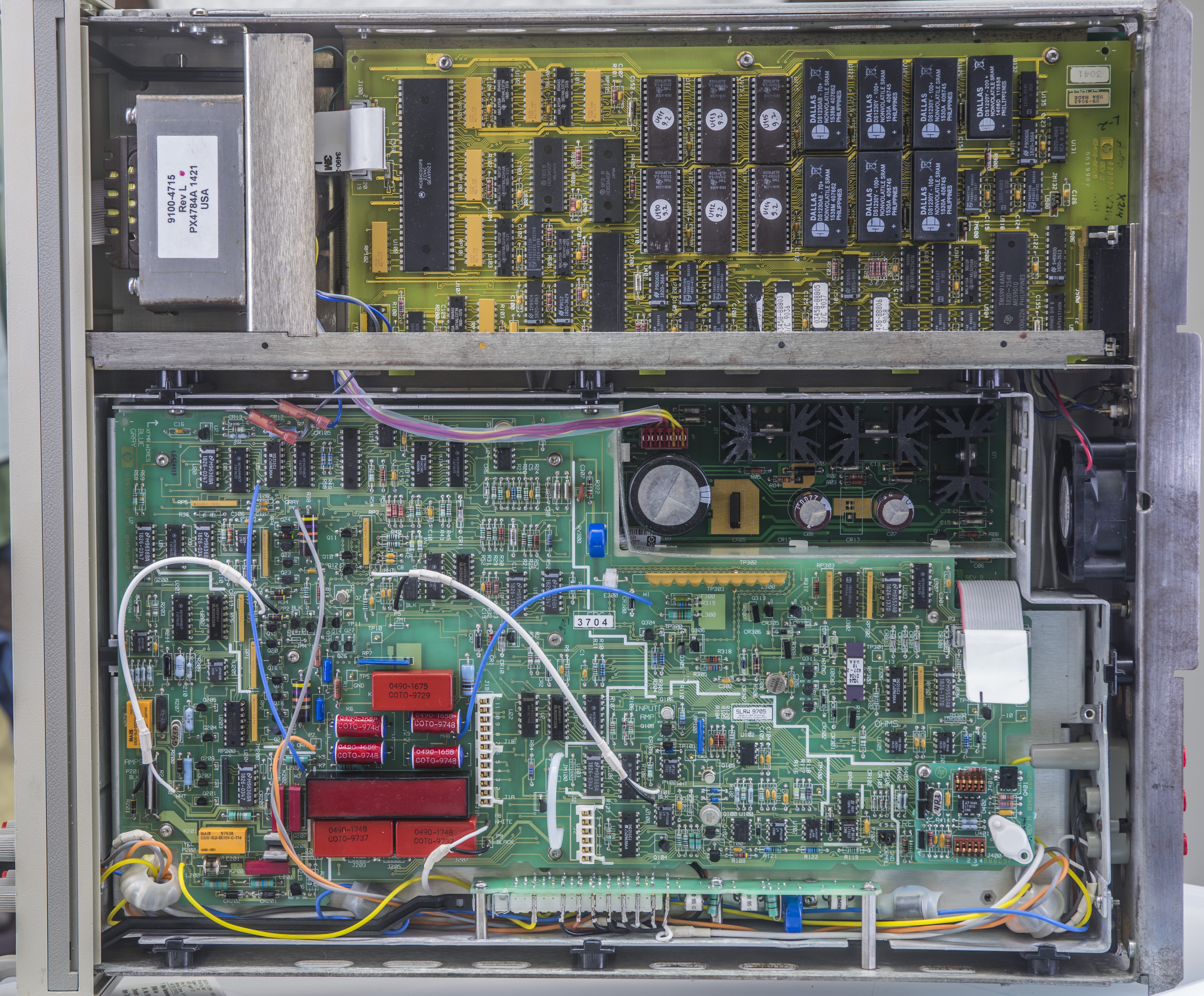
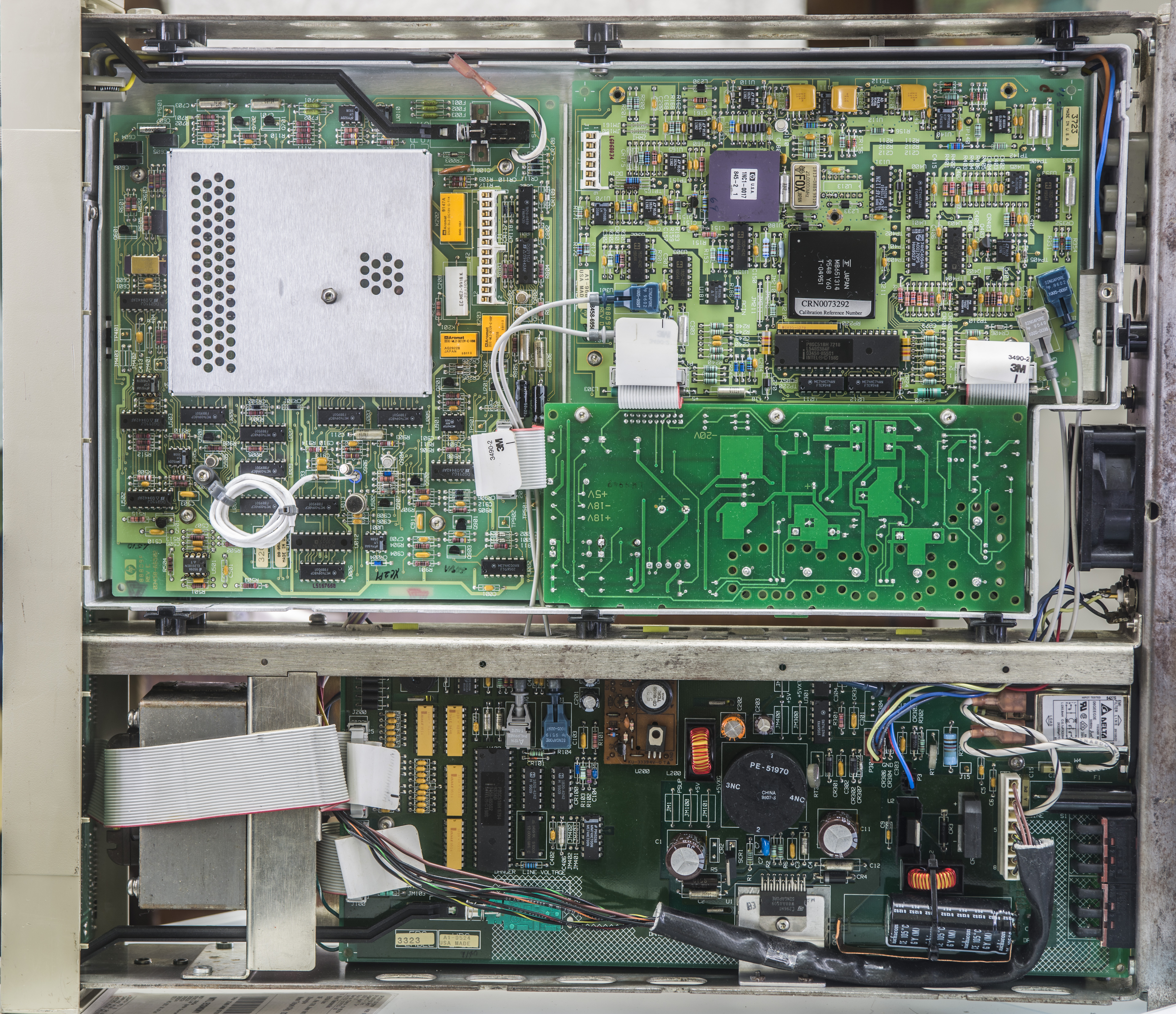
Image 187,188: Final looks, top and bottom side prior to shields installation
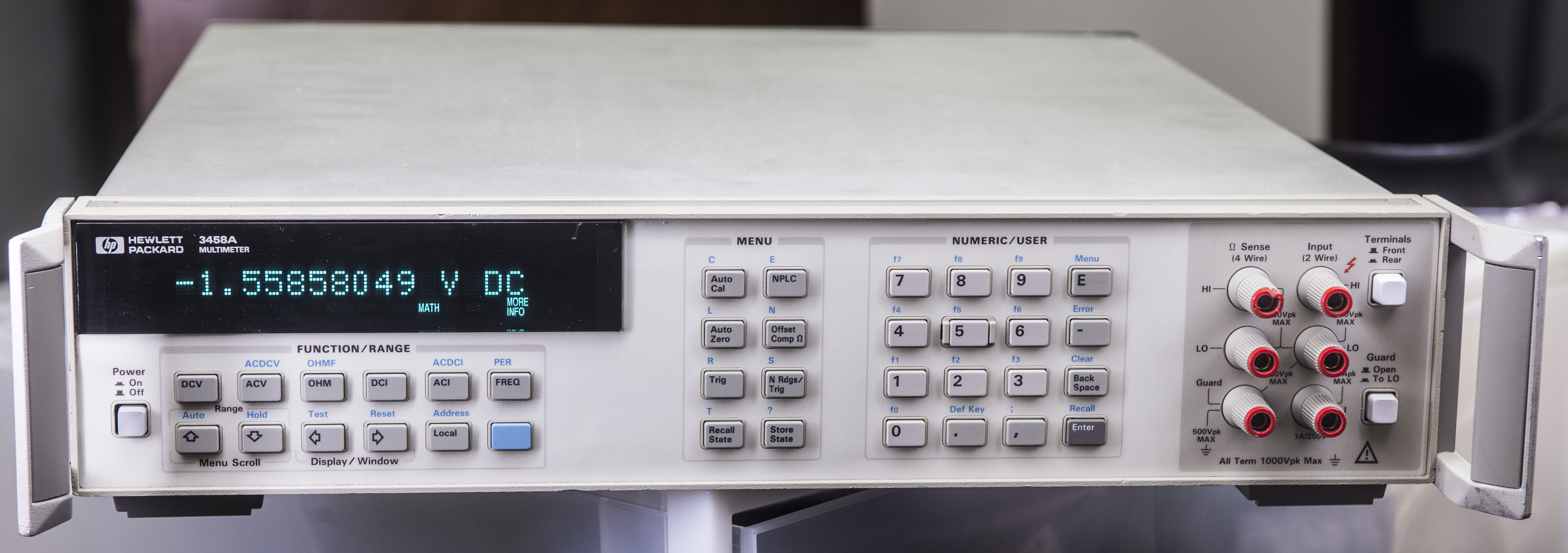
Image 189: Front face of restored HP/Agilent/Keysight 3458A DMM
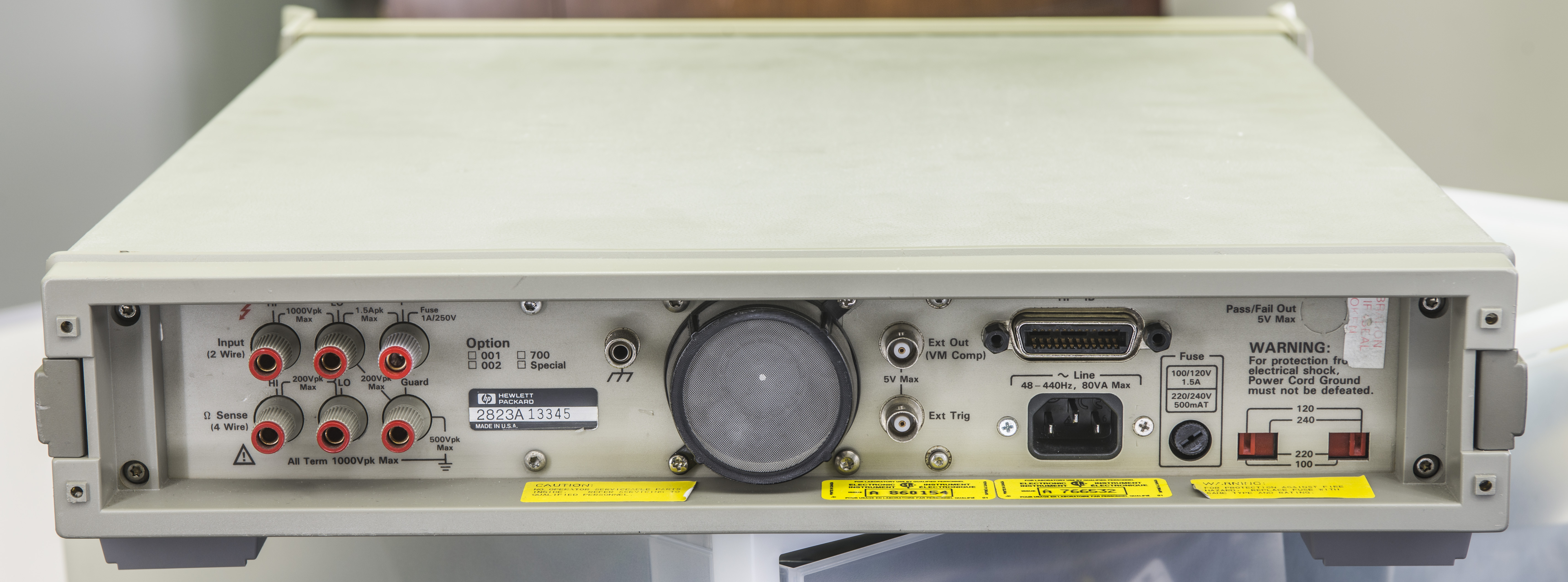
Image 190: Rear panel
Other related documents
Security, Reliability and Backdoors – Interesting security analysis, covering HP 3458A.
OldSchoolTechCorner’s 3458A photos from EEVBlog forum
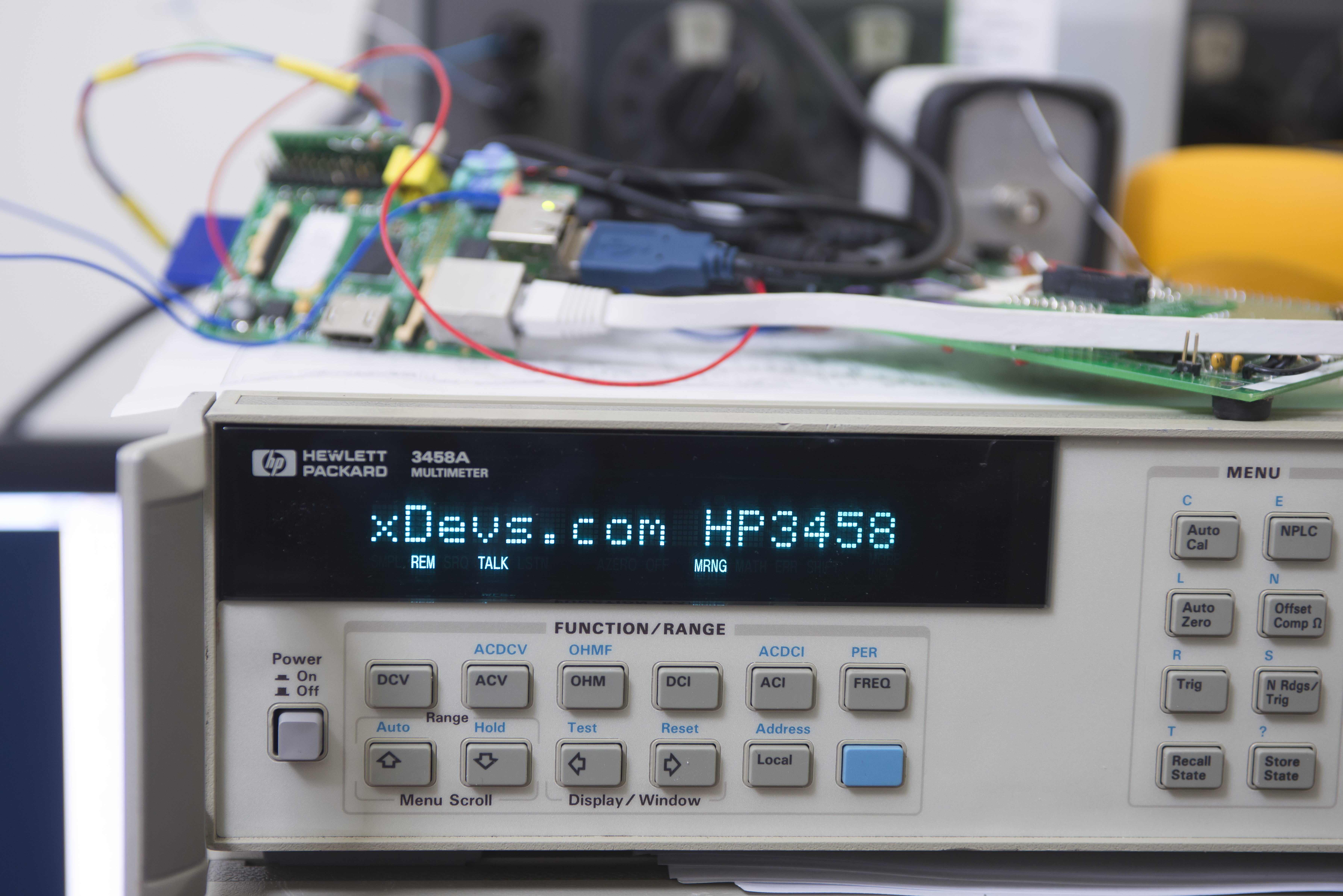
Image 191: GPIB programming demo
Thanks for reading. Hope you like the article, and if you do have any questions, jump in comments!
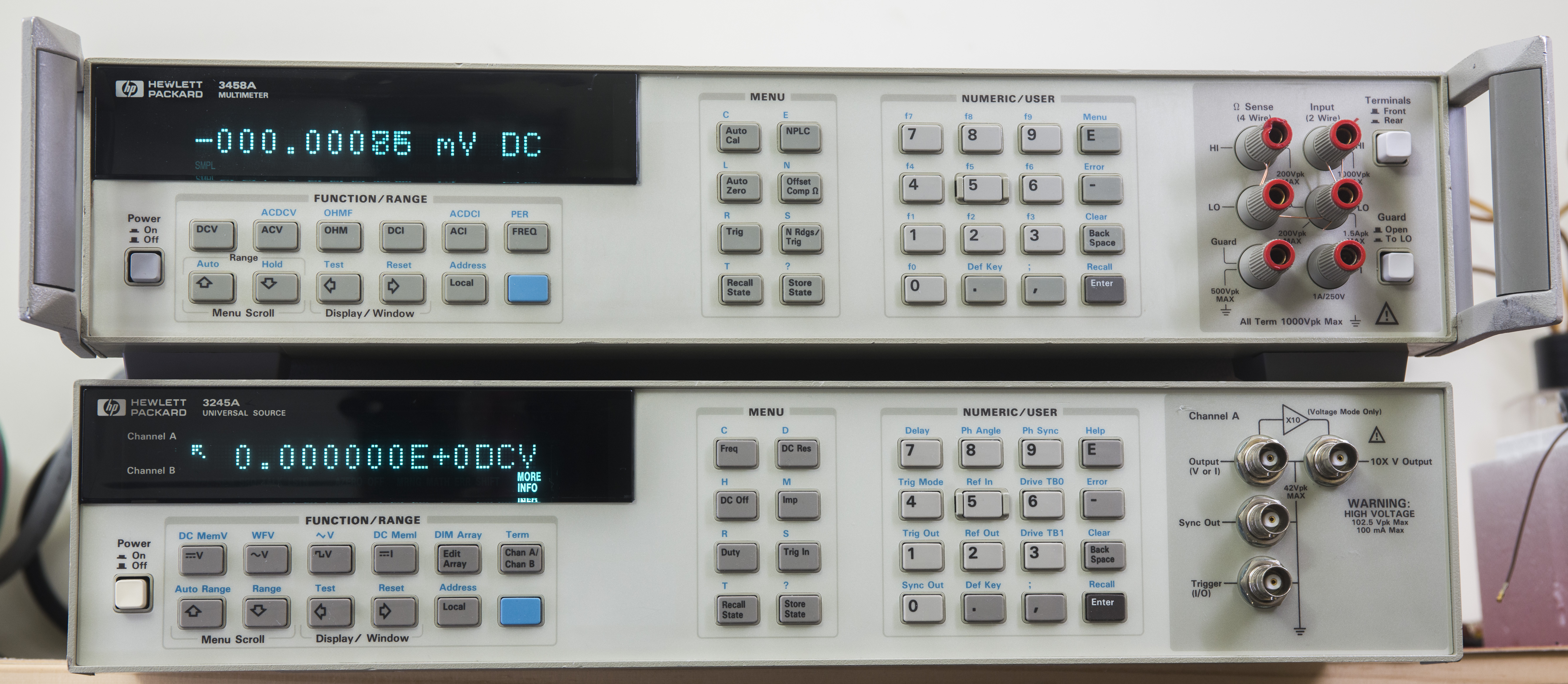
Image 192: Two big brothers, HP3458A DMM and HP3245A Universal source
Article revision: 168
Modified: March 12, 2024, 5:32 a.m.
References
- Geller Labs: The HP 3458A DMM
- Linear : LTZ1000 Ultra-stable reference
- HP/Agilent message group
- EEVBlog forum : Repair log, Old rusty HP 3458A
- Brooke Clarke's repair 3458A article
- Ultra Precise Voltage Reference based on A9 PCBA project
- DC Voltage references solutions
- EEVBlog : HP3458A Schaffner mains line filter failure
- Wiki : Josephson effect use as SI voltage standard
- HP 3245A Universal source article
- Python piece to read 3458A calram
- HP 3458A GPIB remote control guide
- Martin Lorton's Agilent 3458A video
- mjlorton Youtube : HPAK 3458A SNAPHAT ZeroPower Battery Replacement
- EEVBlog : HP3458A input relays discussion
- Keysight product page : 3458A Digital Multimeter, 8½ Digit