- Intro
- Initial photos and conditions
- Day 1: Power checks and initial repair
- Day 2: Diagnostics, A5 board updates
- Day 3: Troubleshooting drift on 100V and 1000V range
- Day 4: More debug on drift 100V/1000V
- Calibration
- Summary
Intro
This time it’s not an eBay acquisition, but rather interesting cowork with local Taiwan lab to help them on 3458A repair. They have rather old 3458A which needed some care and repair attention, and since I know a thing or two about 3458A’s now, we decided to try our luck on fixing their unit. If somebody missed by previous worklog of first rusted meter, here it is.
Initial photos and conditions
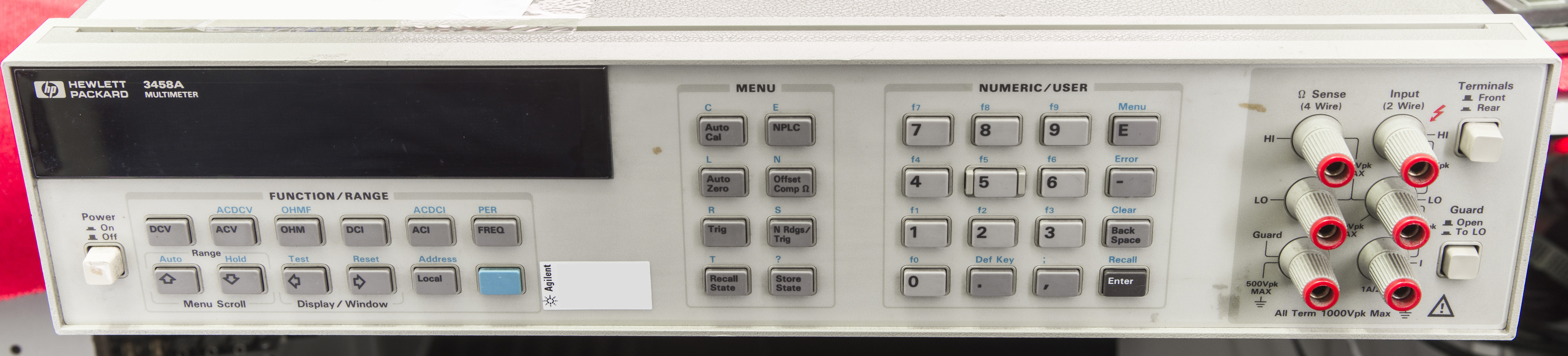
Image 1: Front face of HP 3458A, #3
It’s not shiny new, but still in well condition, without cracks or dents, unlike my own 2nd unit. Still wearing old HP logo, so it’s manufactured before HP T&M division separated into Agilent in 1999.

Image 2: Rear side of HP 3458A, #3
Rear size is bit dusty and dirty, but nothing bad either. Label does not reveal any options, but actually unit itself reports Opt 001 present (extra memory). There is still non-damaged calibration sticker from Agilent on bezel, so it’s a good sign. Meaning, good chance that nobody tried to fix sensitive boards without having proper qualification. It’s obviously serviced by Agilent some time ago.

Image 3: Undamaged Agilent local service sticker
As usual, let’s start with summary list of issues present within the box after initial power on.
- NVRAM issues? NVRAMs replaced to new, socketed A5
- AC Board problems, failure Fixed by F701,Q701 replacement
- A3 stability A3 is stable and good. Phew!
- A5 Firmware update to Rev.9.1 , current fw is Rev 5.3 Done
- Calibration adjustment Calibrated VDC to <2ppm,Ohm,DCI <6ppm, 18 November 2016
- Test stability for 100VDC,Ohm ranges. 100/1kV ranges have +0.9ppm/hour drift, removable by ACAL. Ohm,ACV is OK.
Day 1: Power checks and initial diagnostics
After check of correct mains voltage selector switches (this is important, and can cause $337 USD minimum repair if unit plugged into 220VAC mains on 110VAC setting!), let’s power unit up and check base measurement function.

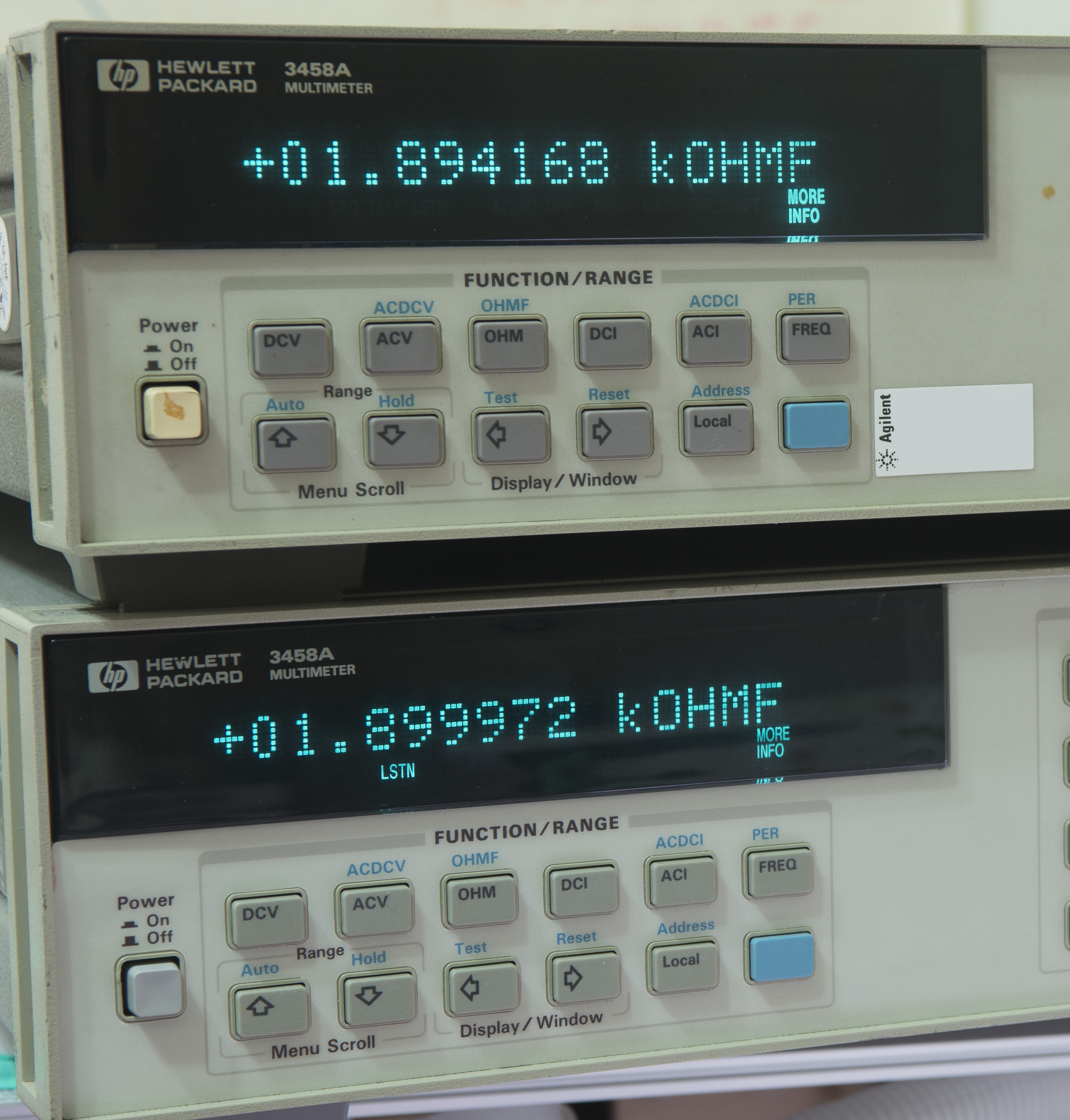
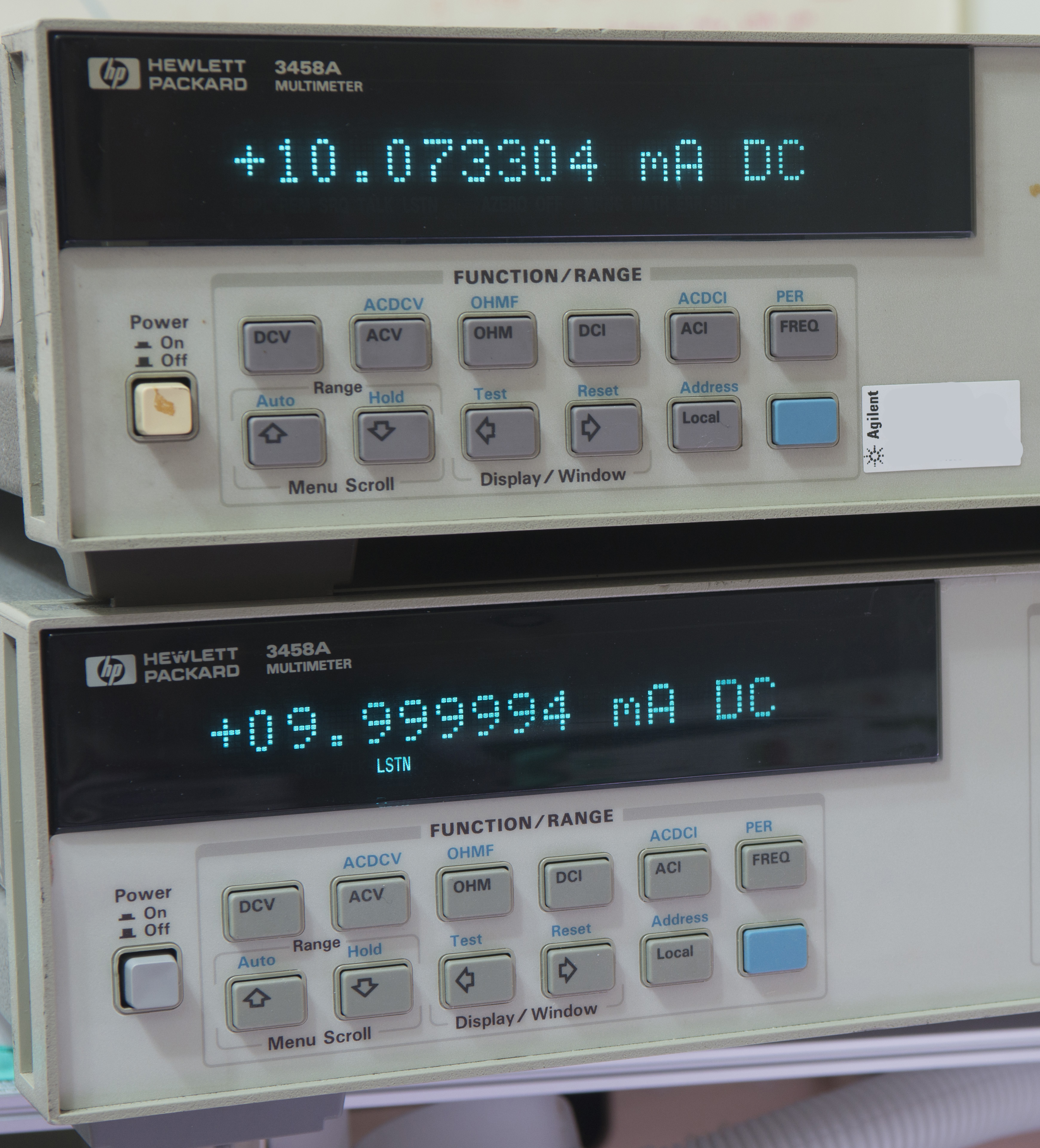
Image 4-6: Initial check with 7VDC, 1.9KΩ and +10 mADC stable sources
Test result not good, as you can see.
| Voltage rail | Expected | Measured | Error | Spec(1y) |
|---|---|---|---|---|
| 7V ±0.5ppm | -7.1637342 VDC | -7.2041502 VDC | +5641.7 ppm | ± 8 ppm |
| 1.9 kΩ ±8ppm | 1899.972 kΩ | +1894.168 kΩ | -3054.8 ppm | ± 10 ppm |
| 10 mADC, ±10ppm | +9.999994 mADC | +10.073304 mADC | +7331.0 ppm | ± 20 ppm |
Table 1: Initial check results as-received
As we see, in received condition unit is barely has performance of average handheld 4½-digit DMM. Clear indication of failure, as even 20 year old unit with only factory calibration cannot drift so much off the spec.
Self-test failed as well on AC stage, giving error Flatness DAC Convergence : 198 which is test for 10V ACV range/function. Later after ACAL ALL attempt unit stopped operation with 202 HARDWARE FAILURE: SLAVE TEST – AC BOARD error message. It hints that A2 AC PCBA is faulty.
Additional confirmation is also incorrect reading on ACV, ~18.xxx VAC on 100VAC range and ~187.xxx VAC on 1kVAC range. There was no reaction or reading change on either short or open at input terminals.
Time to remove the covers and check boards for any obvious and visible component damages.
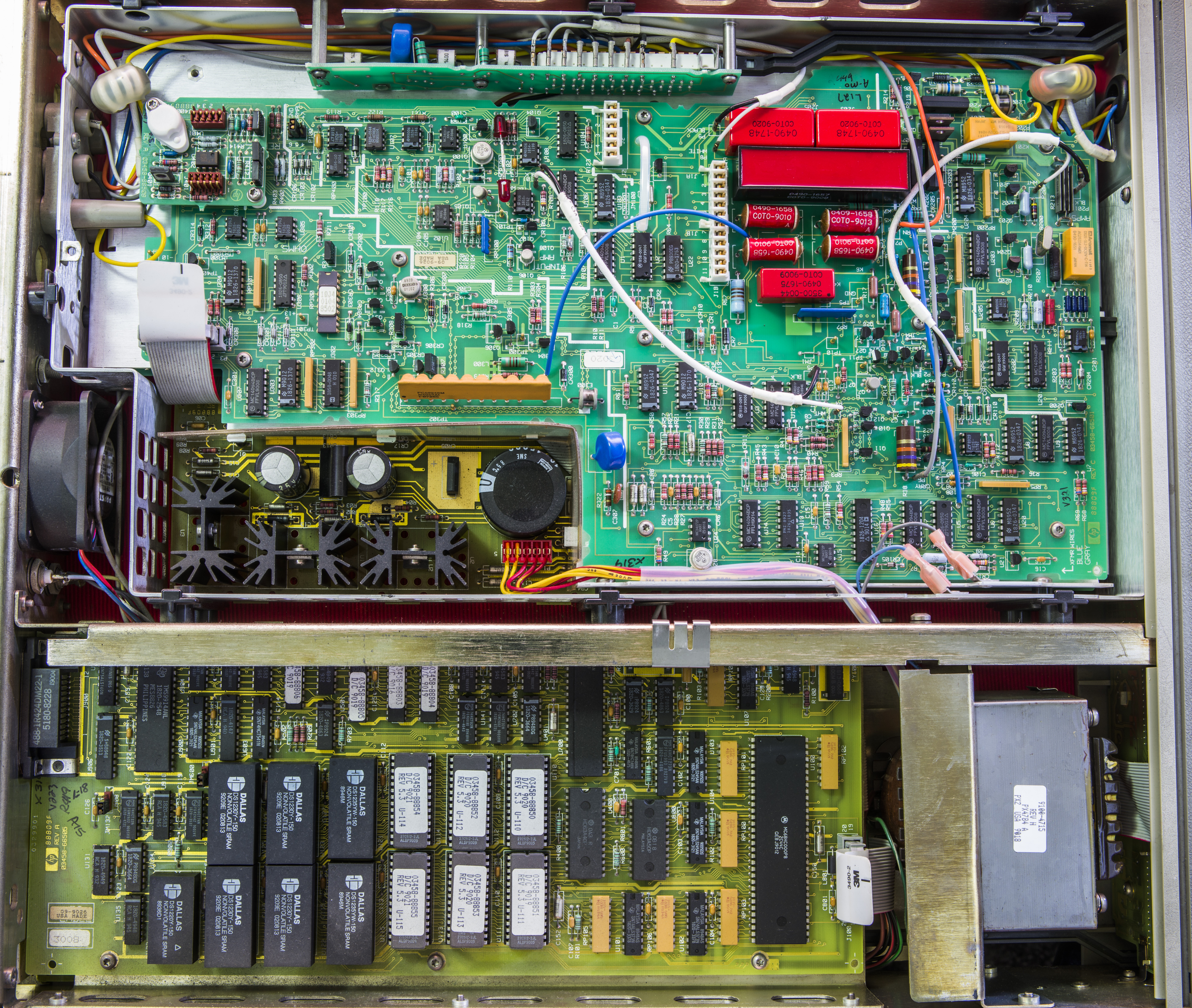
Image 7: Top side with covers removed
All boards visible on this side are original, with manufacturing date codes from year 1989-1990. It’s even older than my own first HP 3458A. A9 DC reference module board is standard 8ppm/year model P/N 03458-66509, as expected.
A1 DC board is older Rev.C with weird and strange construction with two red 5mm LEDs hanging back to back on CR108 position. This position is supposed to be populated with 3V Zener diode, just like in newer A1s.
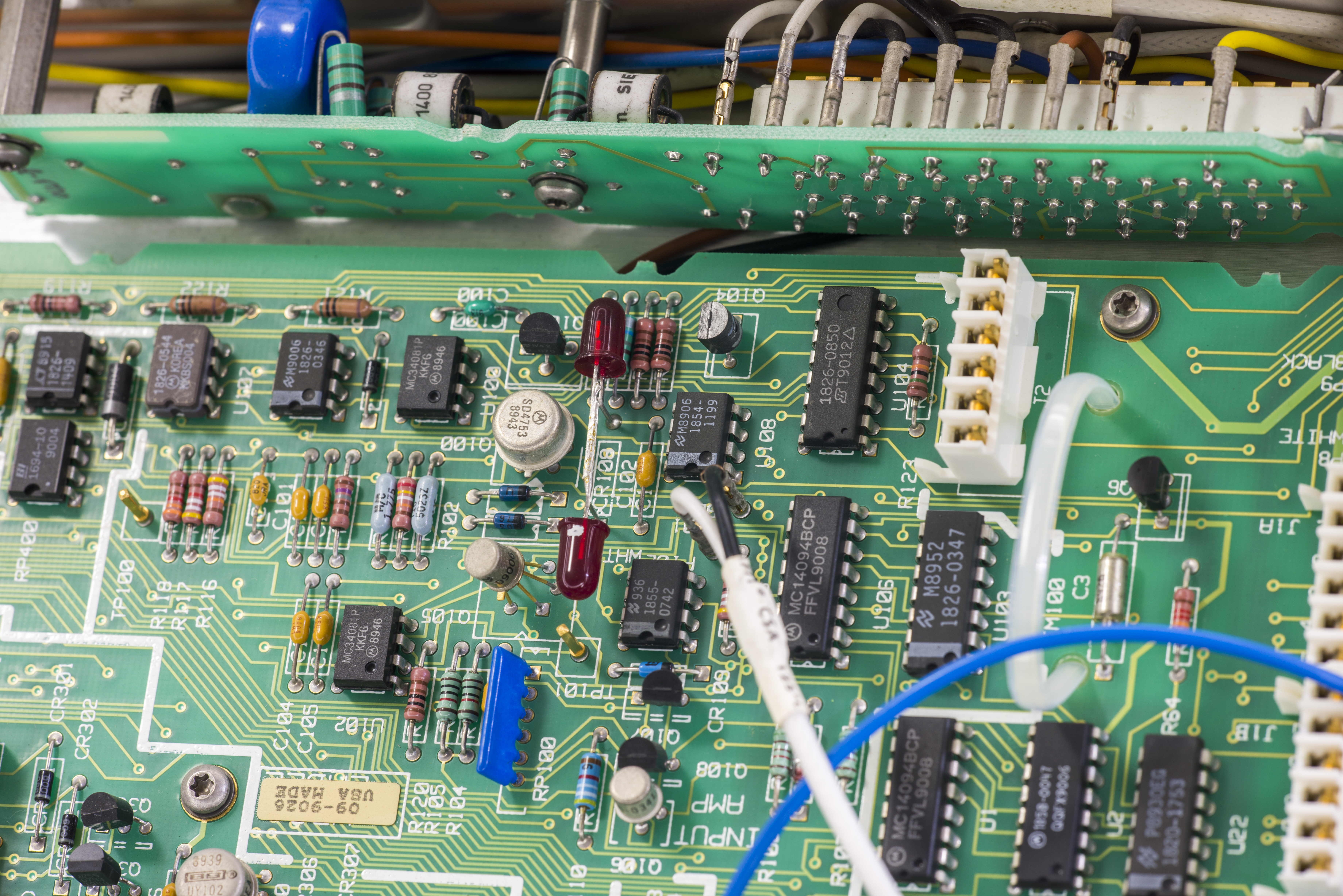
Image 8: Interesting LEDs instead of 3V zener
Perhaps HP factory ran out of 3V zeners and needed this unit built for customer, pronto? :)

Image 9: A1 PCBA revision labels
Also there is no Q102 on Rev.C A1 board either. Reference 40 kΩ resistor is hermetic Vishay Precision Group part with custom part number.
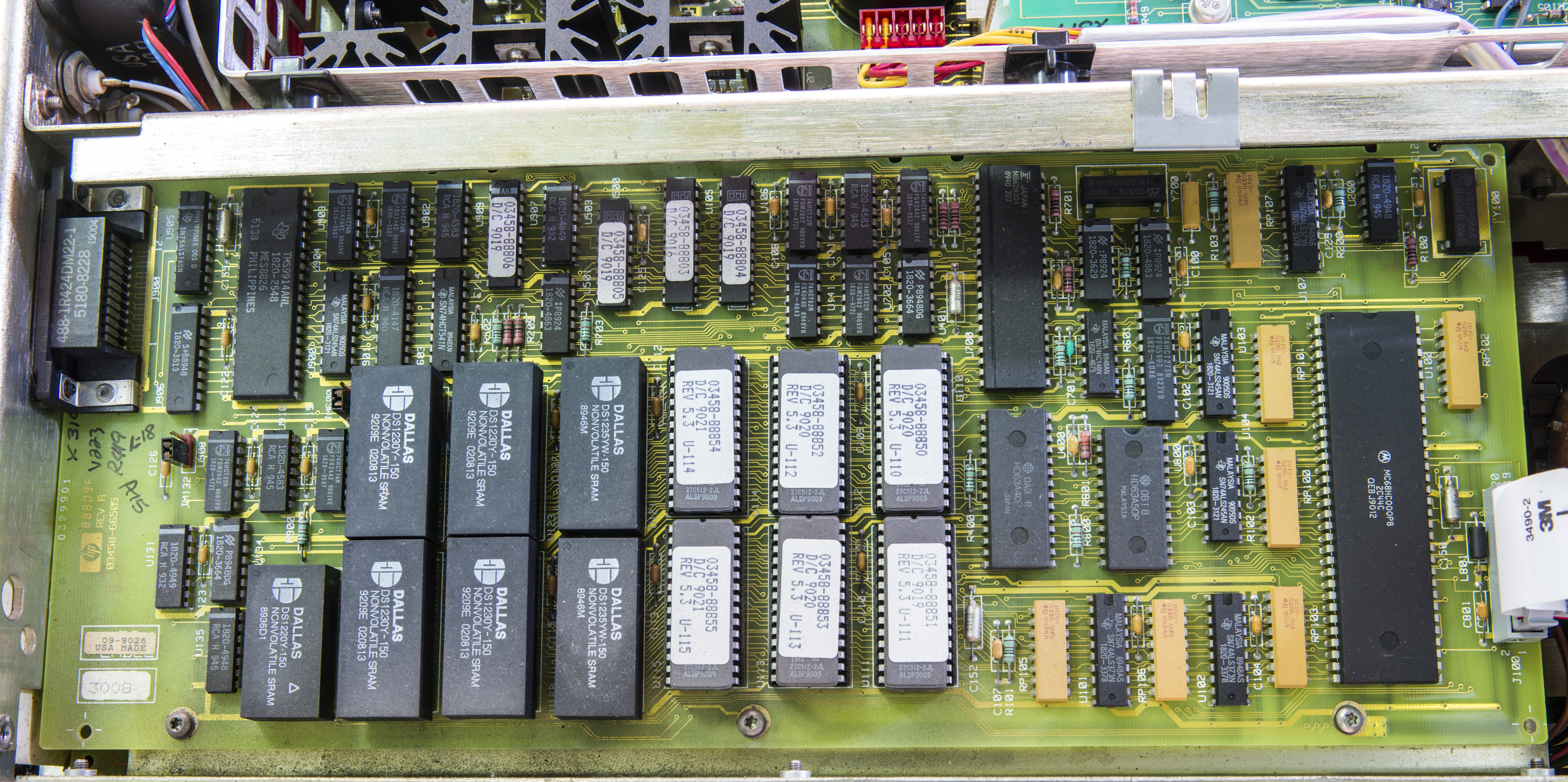
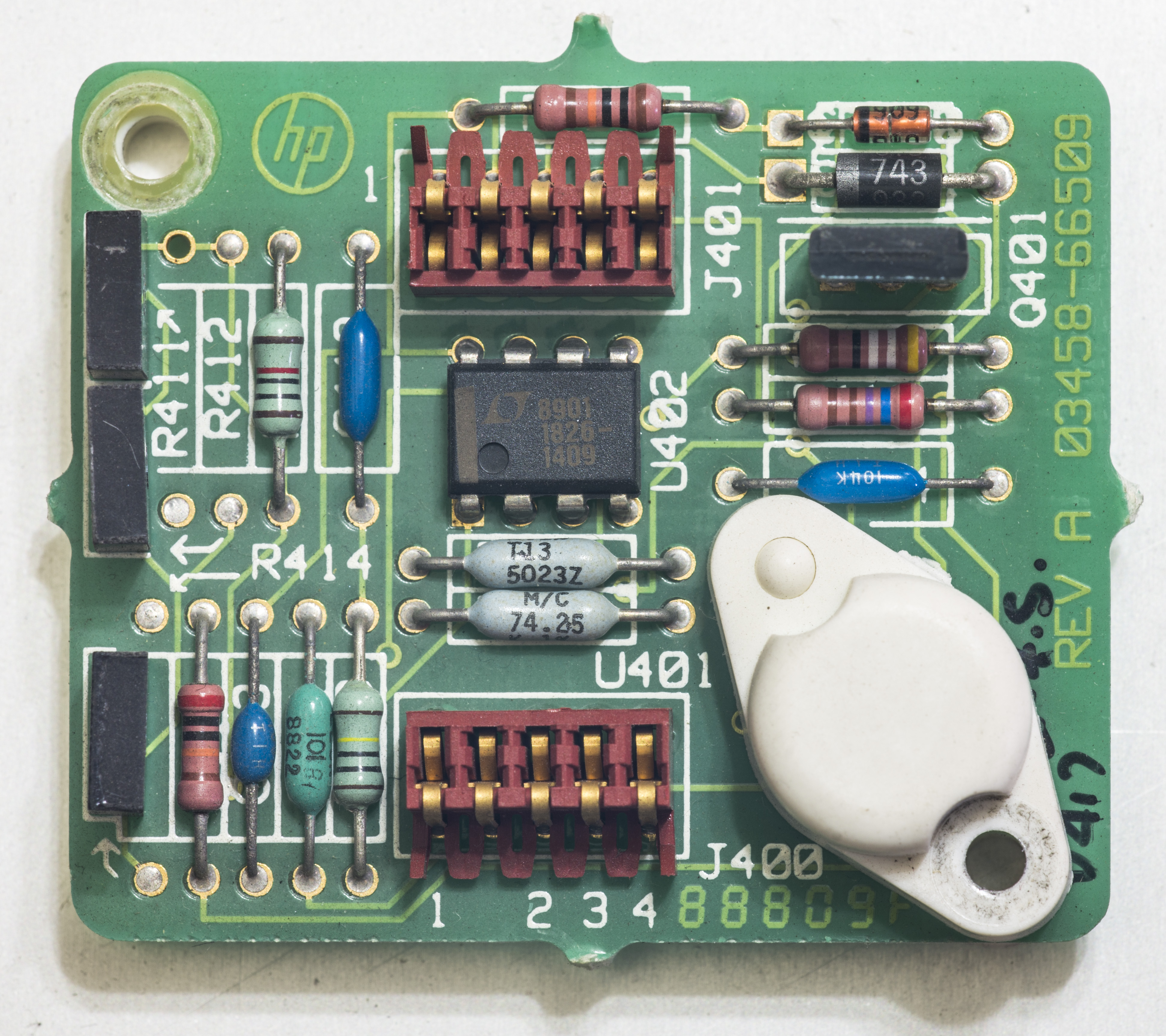
Image 10: A5 PCBA
This is old A5 outguard controller board, same as one in my first 3458A with EDIP-packaged NVRAMs. Firmware is stored in six UV-erasable EPROMs 27C512, revision 5.3 from week 20 year 1990. We can update it with help of UV-lamp and usual ROM-programmer, such as cheap TL866CS.

UV rays can harm your sight and vision. More than 99% of UV radiation is absorbed by the eye. Corneal damage, cataracts, and macular degeneration are all very possible chronic effects from UV-light exposure and can ultimately lead to blindness. Melanoma, a type of skin cancer, can also develop within the eye. Wear protection goggles if using UV-light lamps and keep area well ventilated to avoid high ozone concentration.

Image 11: Old NVRAM still work after 27 years!
Also board can enjoy little bit of cleaning from dust and rust.
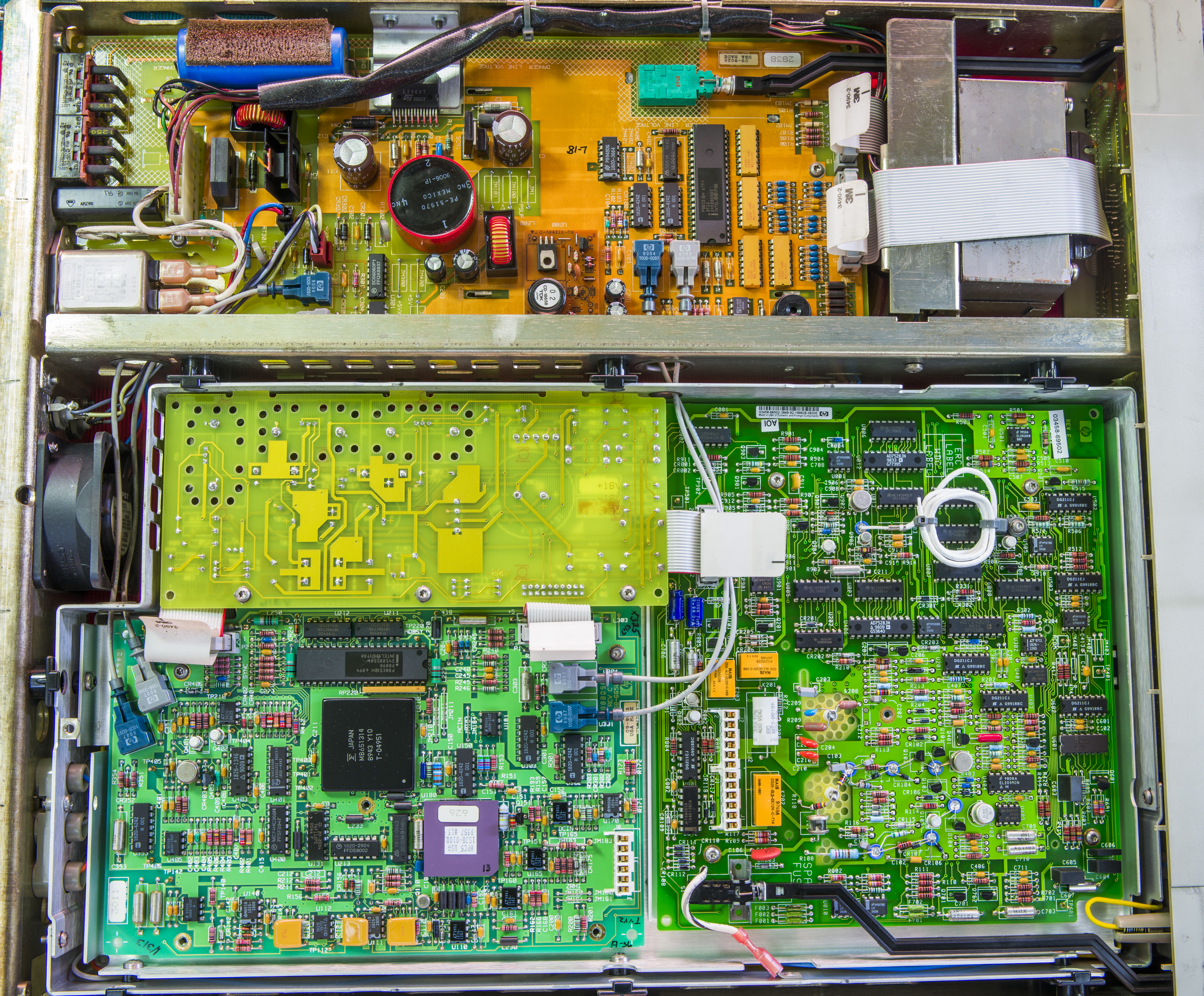
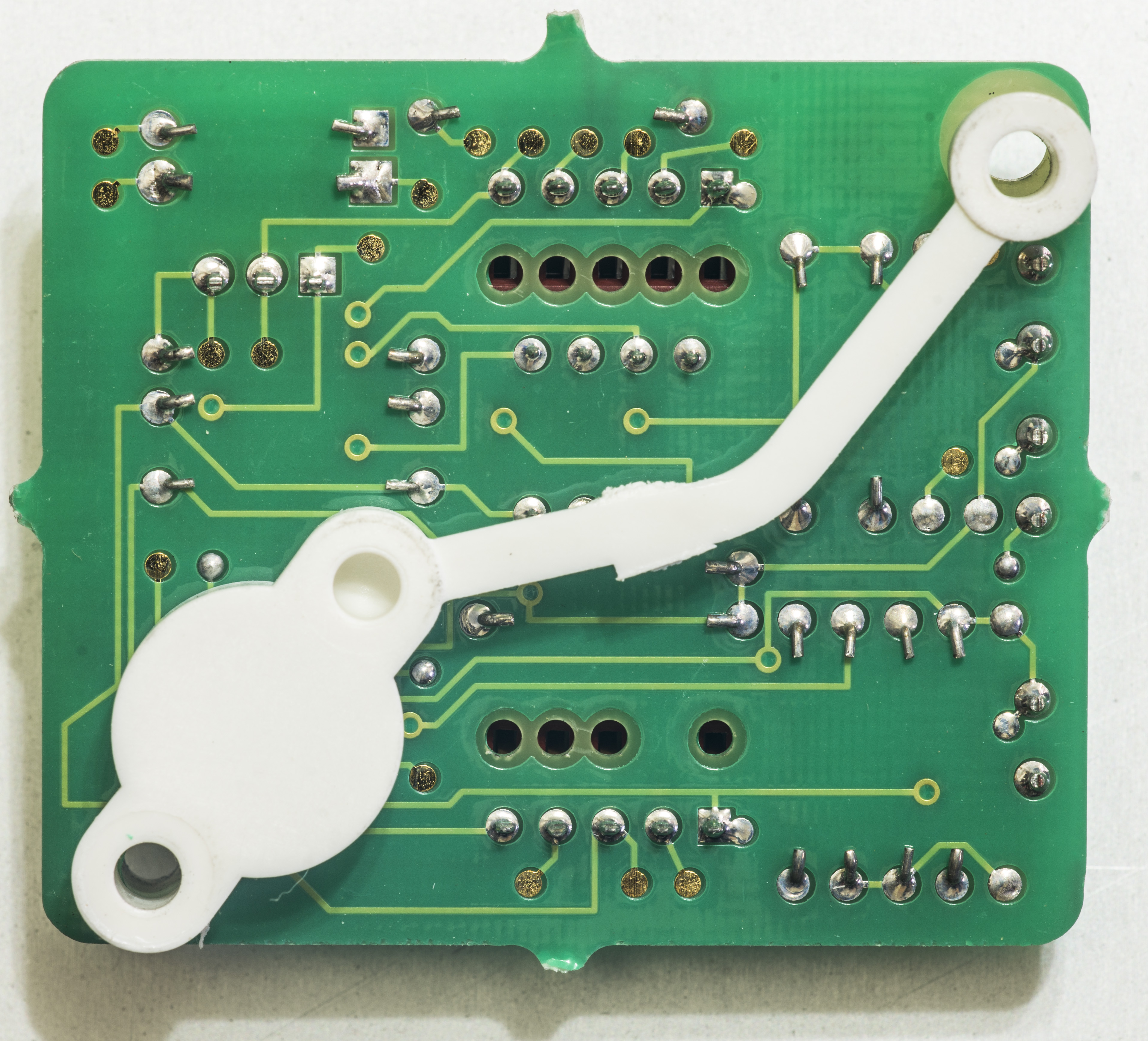
Image 12: Bottom side with covers removed
Schaffner dated 1984! Need to replace this EMI filter, if we want to ensure safe and long operation of the unit. These filters are prone to fail and burn if you get “lucky” with bad batch.
I will also replace those capacitors on the A6 power supply board, just to be on safe side. 27 years is not a small duration even for best top tier capacitors.
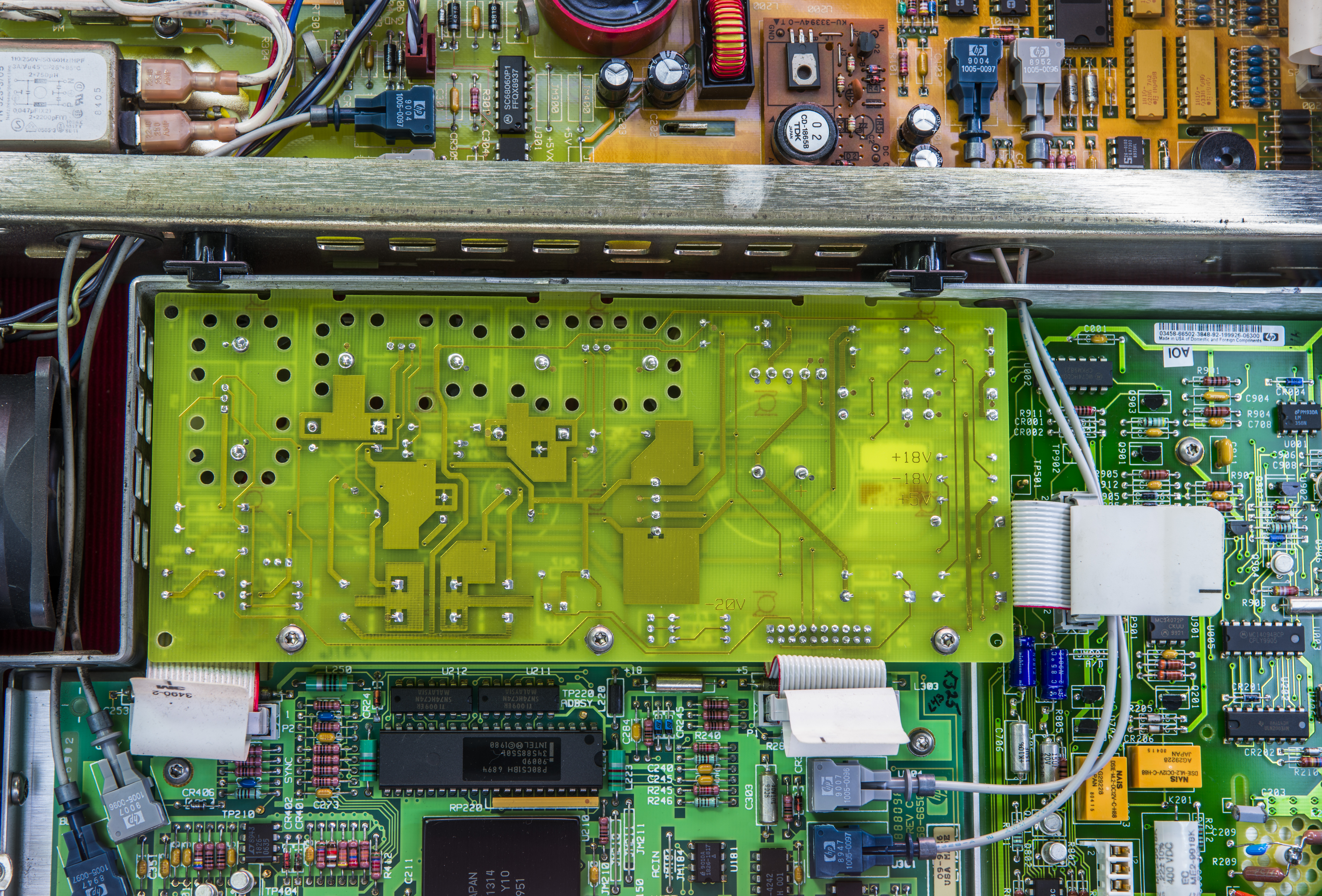
Image 13: A4 inguard supply PCBA, bottom side
No charred zeners, this board is good to go. Capacitor replacements wouldn’t hurt though, same as A6.
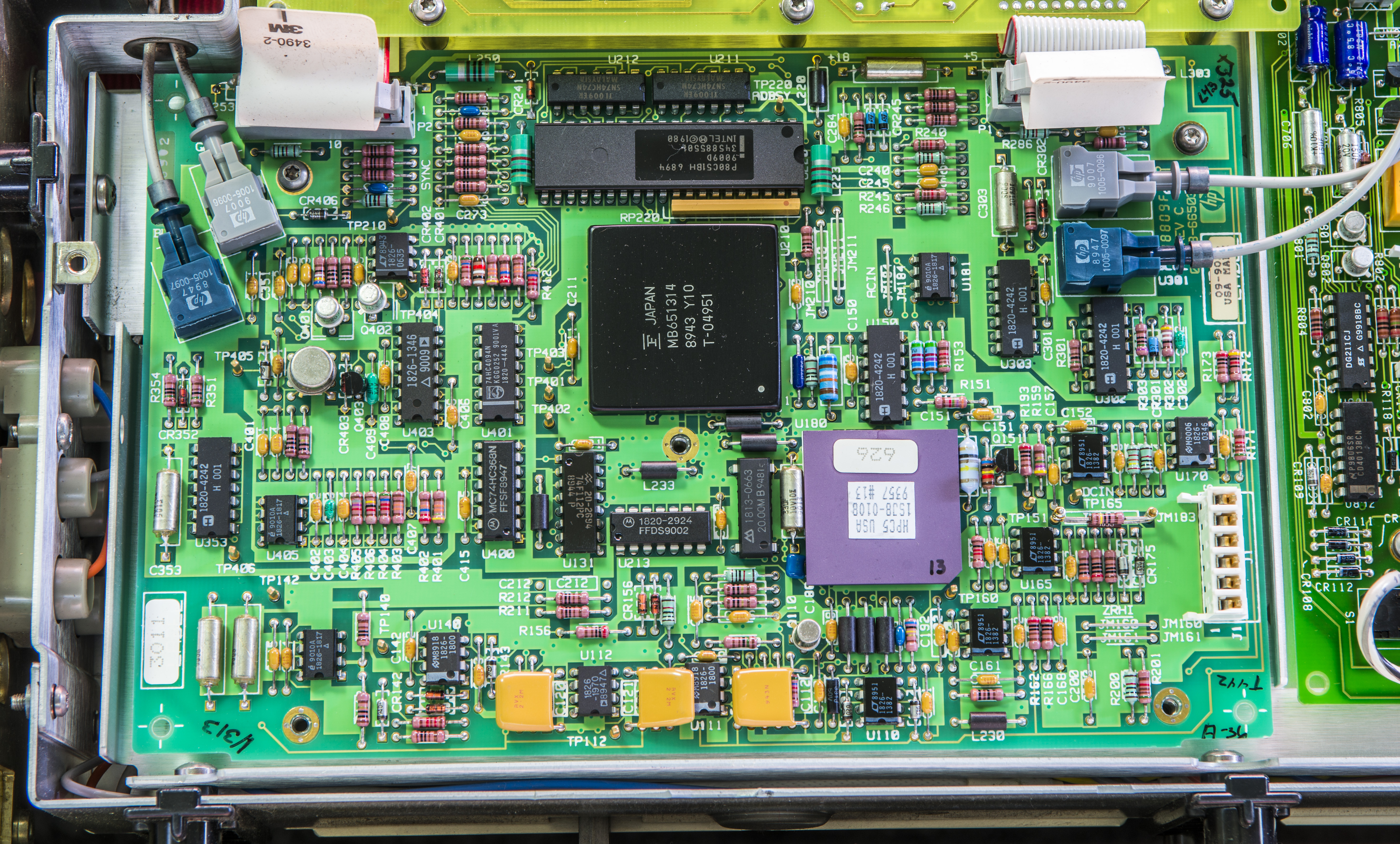
Image 16: A3 A/D Converter PCBA w/o cover
This is older 03458-66503 Rev.C board, with bit different layout than newer A/D boards. This is the board which matches original drawing and schematics of public HP 3458A Component-Level Information Package document with schematics. It also has U213 populated, but already late enough to feature two tantalum caps near ERC tag location.
Famous hybrid ASIC U180 marked as HPC5 USA 1808-0108, manufactured in 1993?. Let’s hope it does not have drift or convergence issues, or this repair would be no fun.
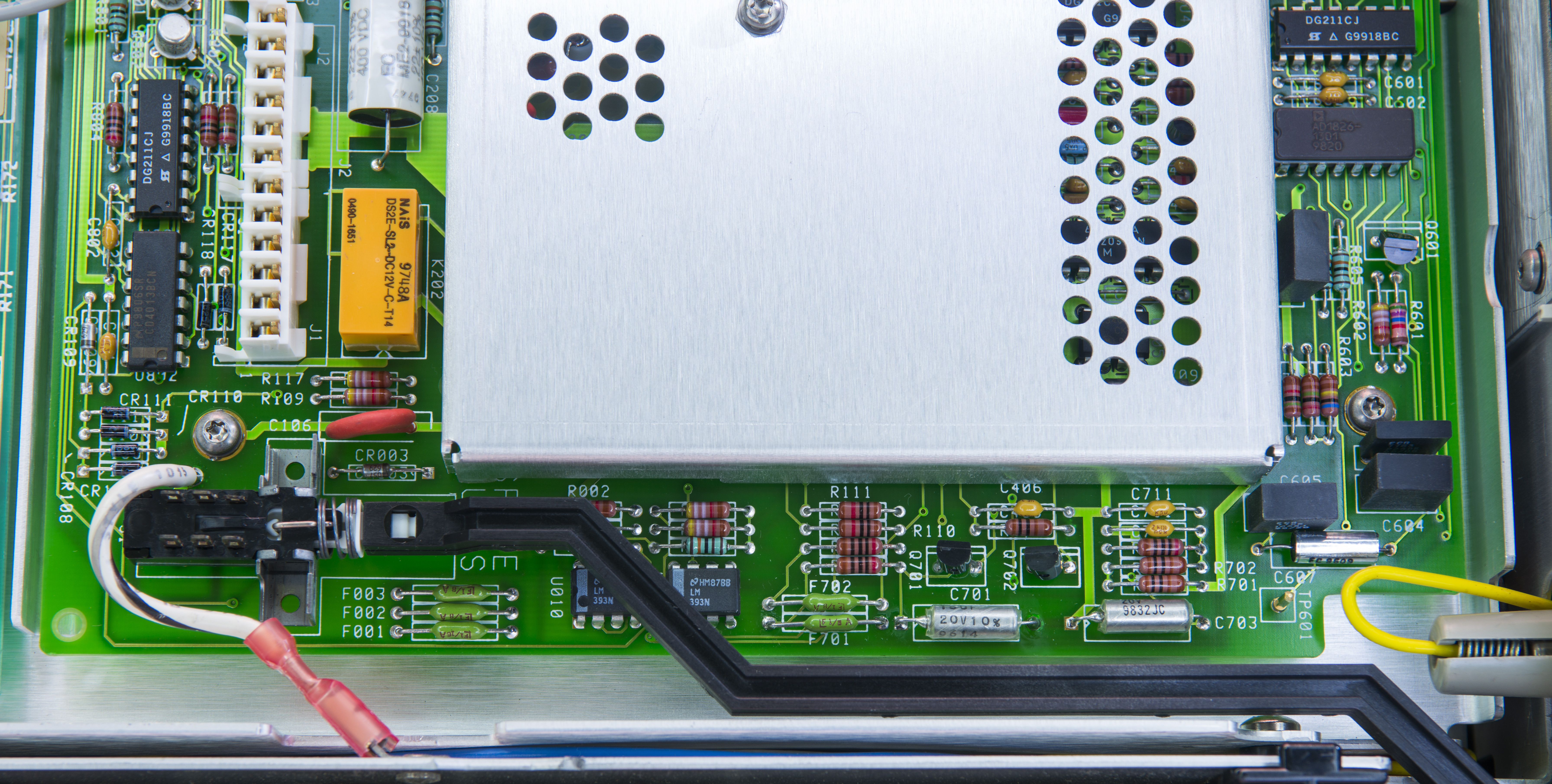
Image 14: A2 AC PCBA
This board was clearly replaced by Agilent service center before, as it has much newer date codes on packages, around 1998-1999 year, and has Agilent service calibration tag. Also it’s likely a refurbished before board, there is still solder flux residue around parts F701, C701, C709, C710, Q701, C406, Q908 (J304), Q905, Q904, CR901, Q901 (2N3094).
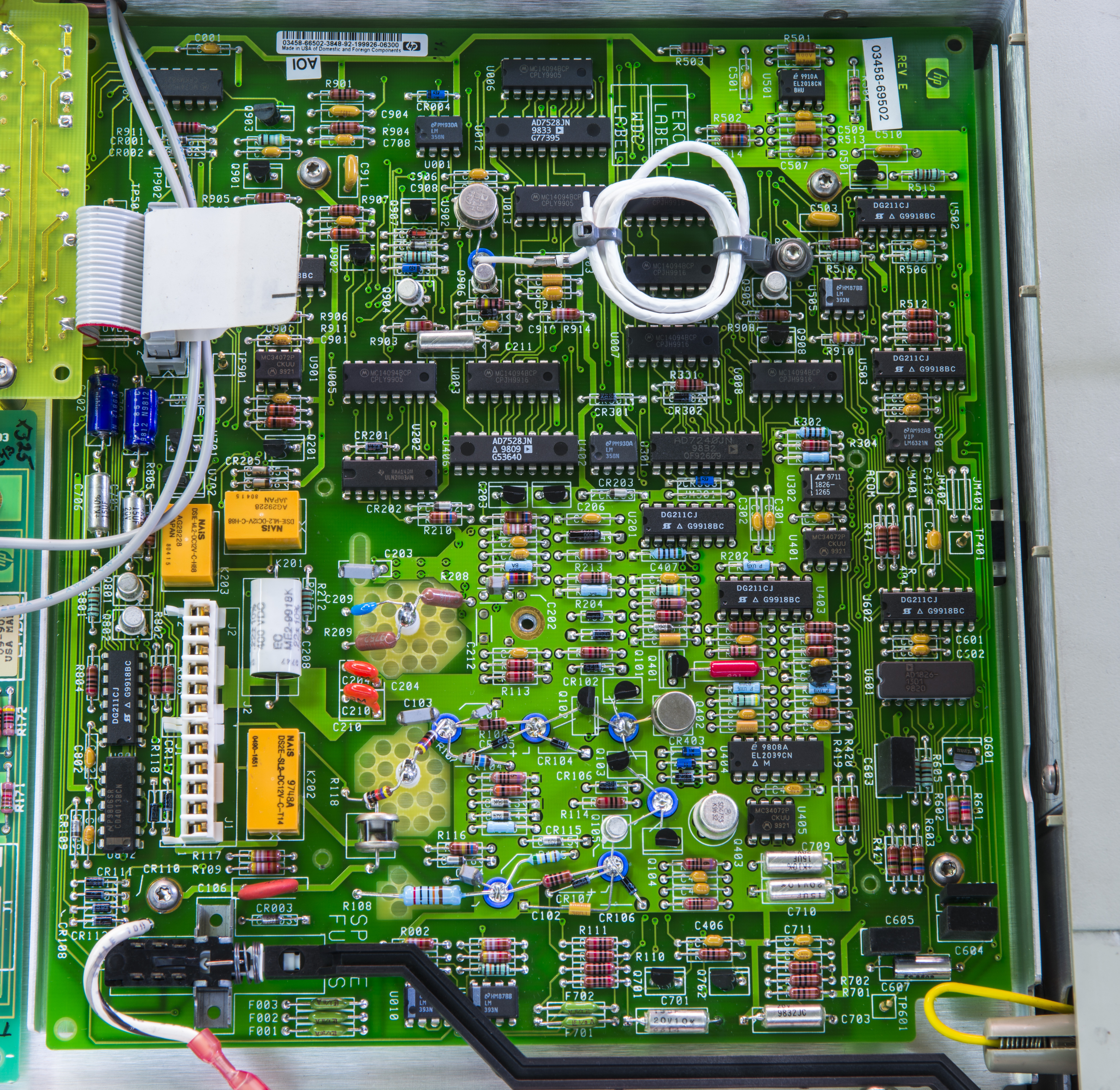
Image 15: Naked A2 without cover, replaced by Agilent before
No visible damages observed, but resistance measurement on fuses revealed blown F701 which is post-regulator fuse on +15V rail.
Repair on A2 PCBA
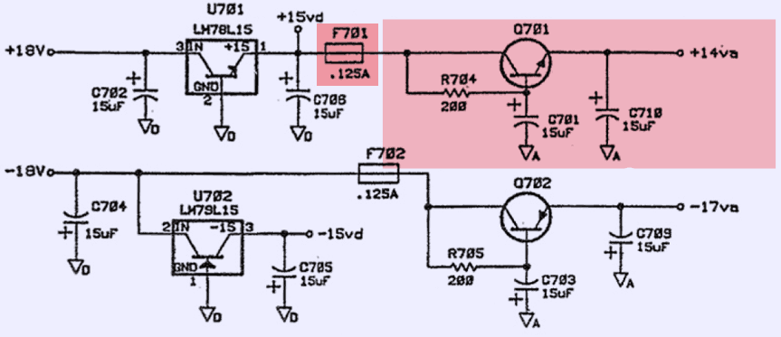
Schematics 1: Affected power rail marked red
Probing around revealed blown fuse F701.
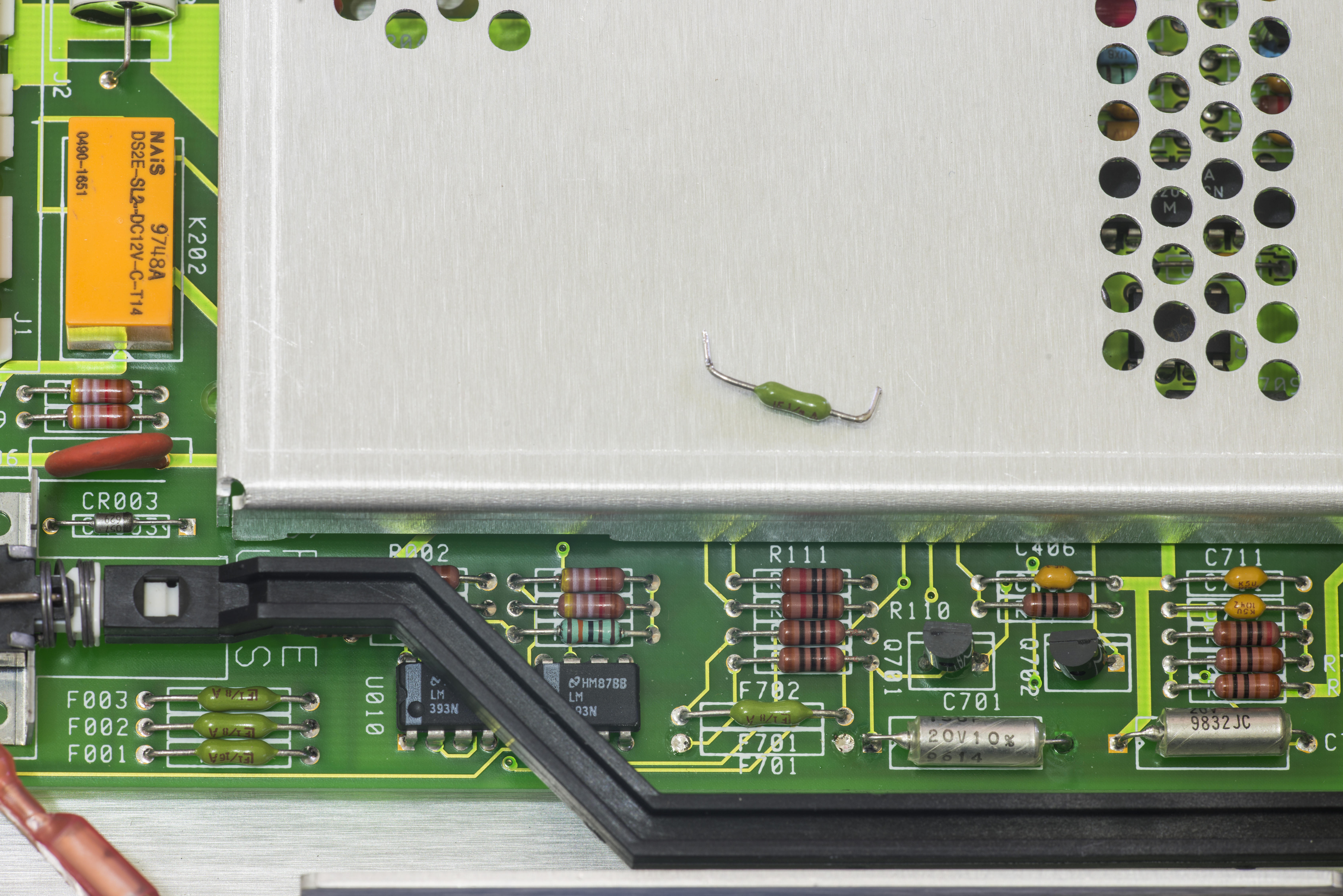
Image 17: Bad F701 1/8W fuse removed
After removal of bad F701 fuse and suspected Q701 2N4401 NPN transistor power supply line +14va was powered from external SMU, set to +14.000VDC with current compliance 100mADC for safety reasons. Correct replacement for fuse is this Littelfuse 0251.125MXL 125mA fuse.
This allowed unit to pass full self-test and successfully complete ACAL self-calibration. Current consumption was stable around +35 mADC, sometimes peaking at +39 mADC during AC range relay switching/operation. At power on during meter init current peaks at 56 mADC.
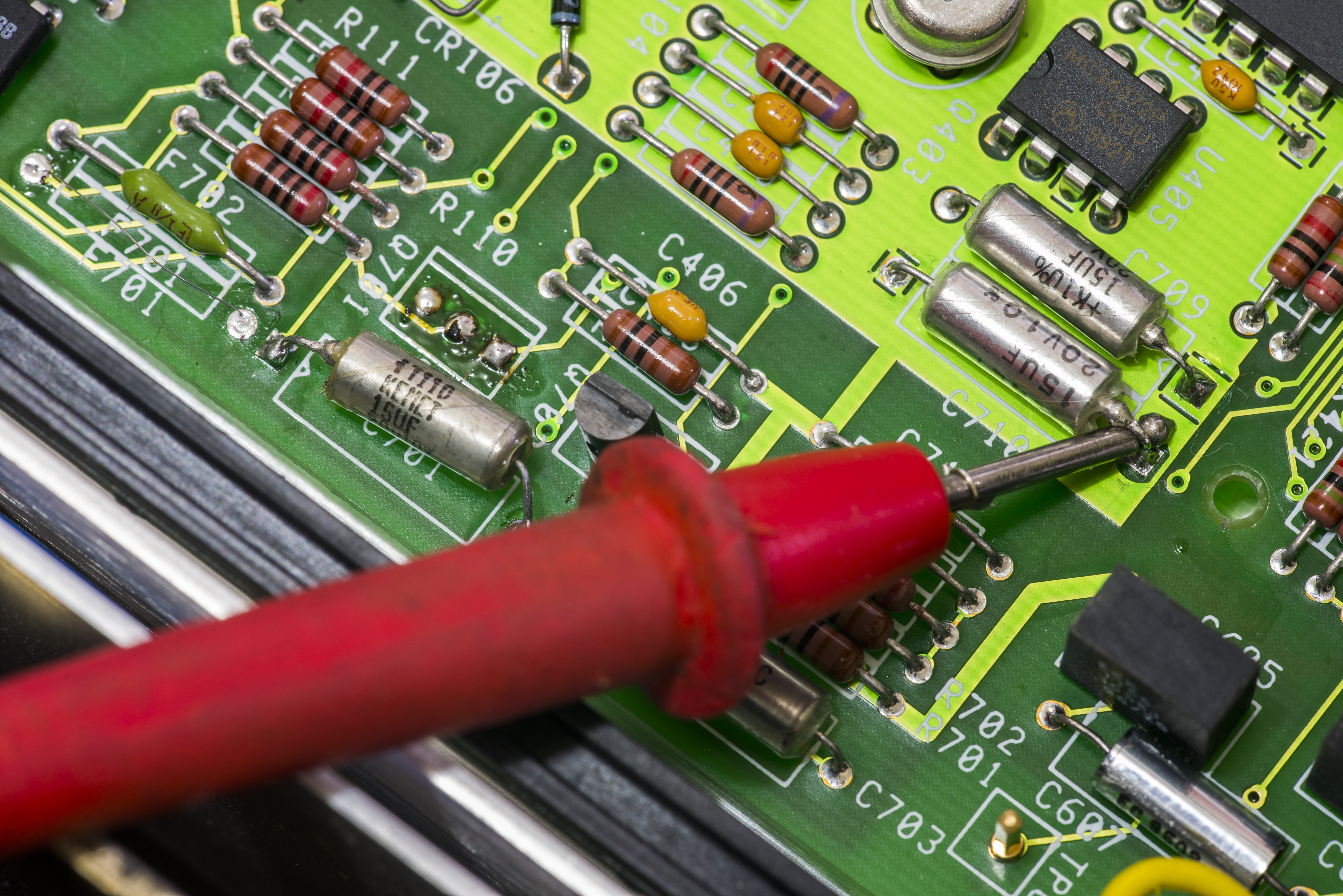
Image 18: Measurement of +14va power rail during test
After 200 Ω resistor test, other parts that got replacement are C701, C710, and Q701 with new NPN. This measure resolved issue with +14va rail and provided stable +14.1..+14.2 VDC on C710. This also fixed error offsets on the DCV/OHMF/DCI functions as well!
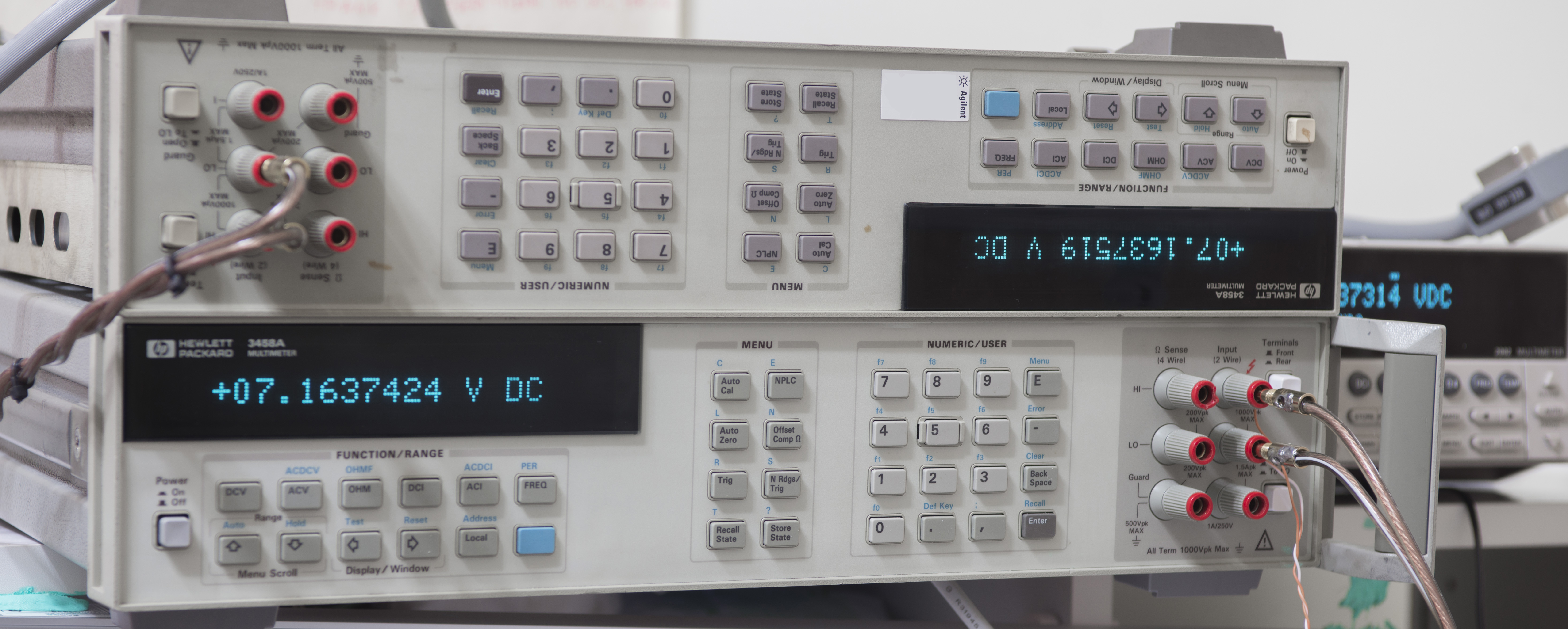
Image 19: Happy brothers under cross-comparison test. Reference 3458A on bottom
| Voltage rail | Expected | Measured | Error | Spec(1y) |
|---|---|---|---|---|
| 7V ±0.5ppm | +7.1637424 VDC | +7.1637519 VDC | +1.326 ppm | ± 2.55 ppm |
| Extended test for 7V | +7.1637466 VDC, Live data | +7.1637324 VDC, Live data | <2.2 ppm | ± 2.55 ppm |
Table 2: After A2 repair test results
Day 2: Diagnostics, A5 board updates
NVRAMs usually live 10-15 years max, but in case here very old NVRAMs with date code 1989 still operated normally and did not give errors on data tests! Anyhow, leaving them in the board any longer is playing with luck, so fresh NVRAMs installed on all positions.
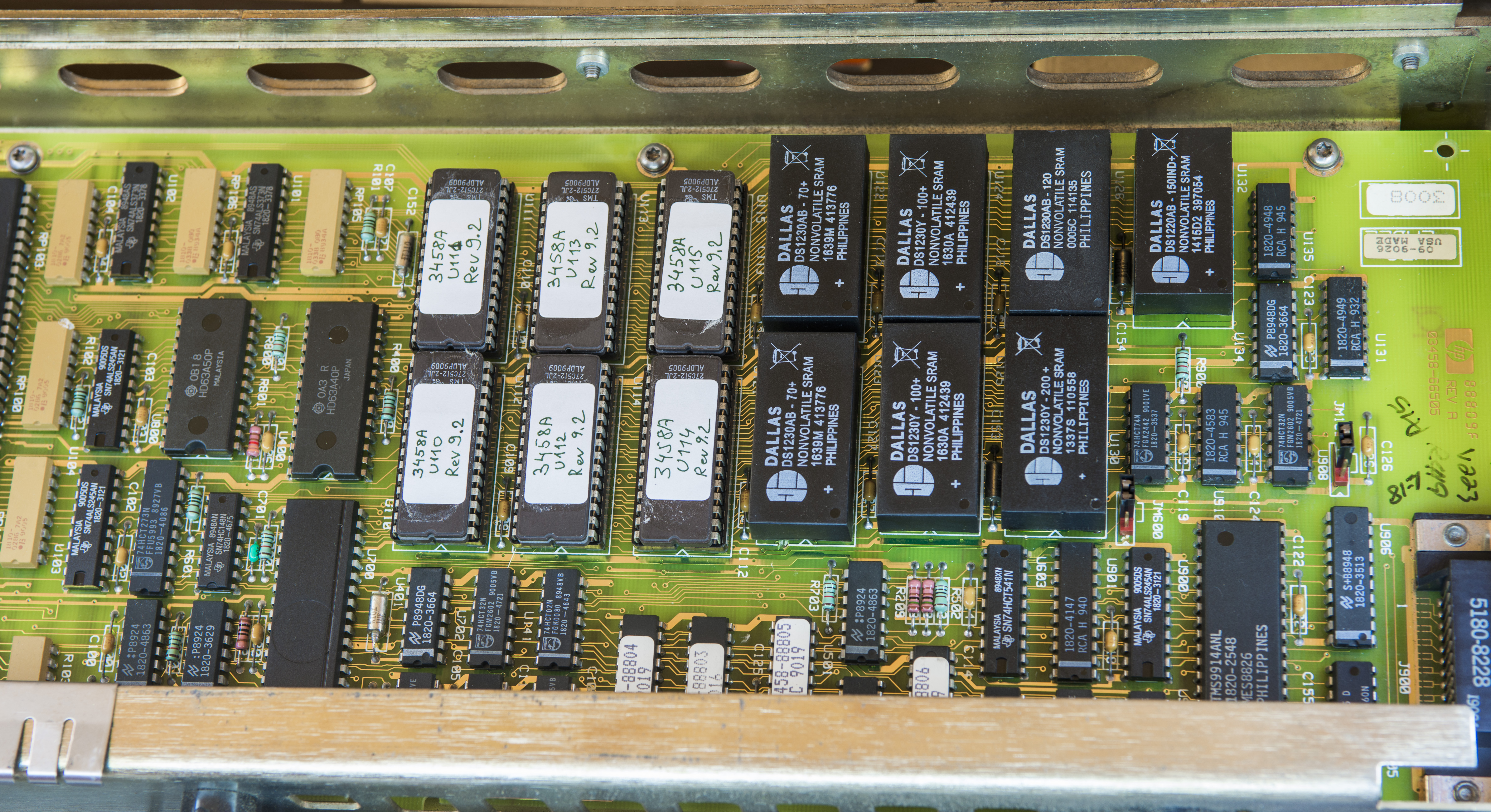
Image 20: A5 PCBA with updated Dallas NVRAM and Firmware ROMs
Firmware is Rev 5. Time to update to latest Rev.9. Here is collection of firmware ROM dumps for reference.
Firmware ROM dumps for HP/Agilent/Keysight 3458A, read by general purpose ROM programmer. From information we have, firmware dumps are compatible with all hardware versions.
| ROM | Revision 2 | Revision 4.6 | Revision 6 | Revision 7 (1992) | Revision 8 (1998) | Revision 9 (latest) |
|---|---|---|---|---|---|---|
| U110 | 03458-88820 | 03458-88840 | 03458-88860 | 03458-88870 | 03458-88880 | 03458-88890 |
| U111 | 03458-88821 | 03458-88841 | 03458-88861 | 03458-88871 | 03458-88881 | 03458-88891 |
| U112 | 03458-88822 | 03458-88842 | 03458-88862 | 03458-88872 | 03458-88882 | 03458-88892 |
| U113 | 03458-88823 | 03458-88843 | 03458-88863 | 03458-88873 | 03458-88883 | 03458-88893 |
| U114 | 03458-88824 | 03458-88844 | 03458-88864 | 03458-88874 | 03458-88884 | 03458-88894 |
| U115 | 03458-88825 | 03458-88845 | 03458-88865 | 03458-88875 | 03458-88885 | 03458-88895 |
| 03458-88887 Single ROM | 03458-88897 Single ROM |
Table 12: Firmware ROM dumps
To combine 6 separate ROM images into single one (for digital board with single 27C4002 EEPROM) this Python app can be used. This was not required though for this particular A5 PCBA.
After reassembly unit powered on just fine, and completed full Self-Test and Acal ALL without issues.

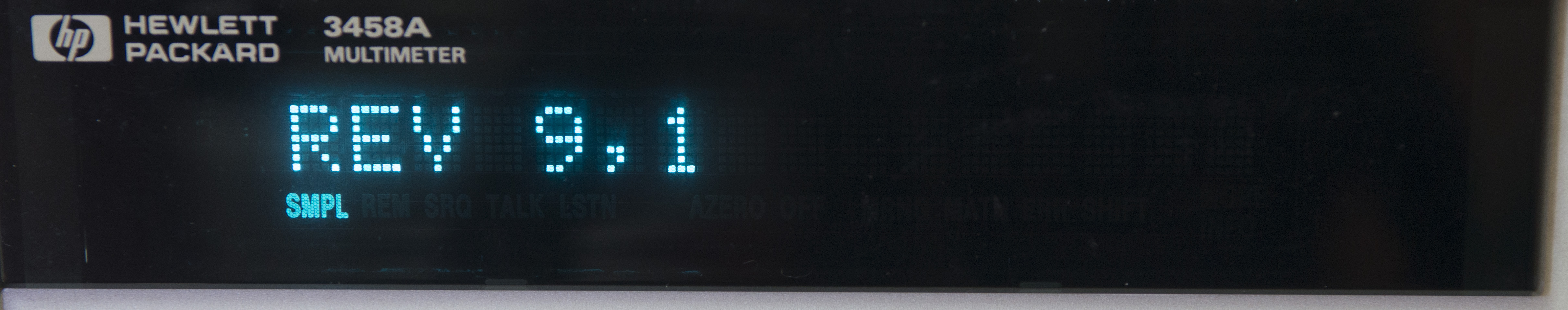
Image 21-22: OPT? and REV? reports
CAL? 1,1 and CAL? 2,1 values presented as well:
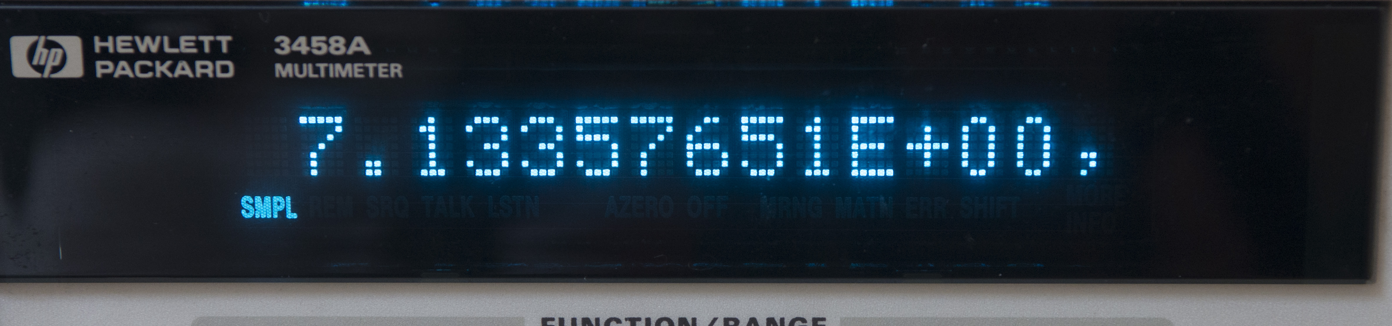
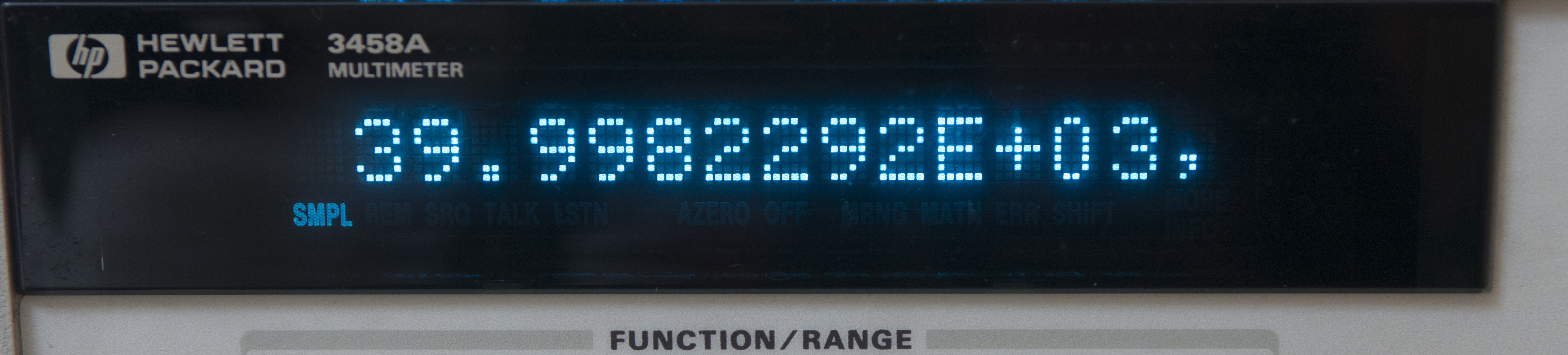
Image 23-24: CAL? 1,1 and CAL? 2,1 reference values report
Unit original other calibration data:
| Value | Meaning | Reading |
|---|---|---|
| CAL? 59 | DCV Cal temperature | 41.23 °C |
| CAL? 60 | OHM Cal temperature | 38.04 °C |
| CALSTR? | Calibration string | Date = Wed Nov 4 07:43:04 1992, Temp(‘C) = 38.1 |
Given test results, meter calibration is likely was happen after 1992, otherwise it would be extremely good result over all these years, which is hard to believe.
Day 3: Troubleshooting drift on 100V and 1000V range
After initial tests on DCV function abnormal drift at speed +2.8ppm/hour was discovered on high voltage ranges 100VDC and 1000VDC. Lower ranges, 0.1V, 10V were stable and agree to my reference 3458A very closely, less than 0.2ppm over more than 10 hours span, so we know at this point that A3 A/D converter and it’s U180 hybrid are good.
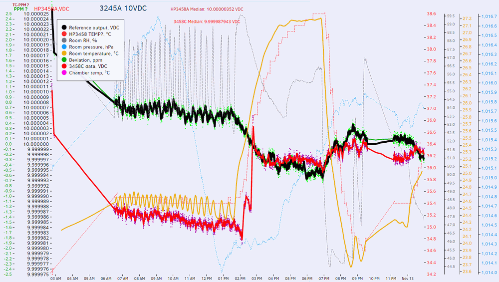
Image 25: Animated graph with stable 10VDC range and faulty 1kV range, showing drift
Note different vertical scale of the graph, which is ±0.5 ppm for 10VDC range and ±4.5ppm for high voltage range.
Black line is reference HP 3458A, connected in parallel to same stable 100V HP 3245A source to ensure that signal drift is not coming from source or temperature variations. “Reset” of voltage back to accurate level, which happen around 9:50 is result of executed ACAL DCV autocalibration, which reset error caused by drift by retaking reference measurement.
This is also very good example to show that SELF TEST PASS happy message CANNOT and should not be used as measure to judge if unit is good and working properly. Self-test procedure is too fast to catch any of these slow drifts. This applies to any DMM, not just HP 3458A we work with here.
Buying used meters, even if they are declared as “good new-old-stock” and have dozen of photos SELF TEST PASS can still mean requirement of repairs or expensive board replacements. Buyers beware. And owners should have logging setups and run own tests periodically, to ensure no hidden issues present. Don’t assume everything is OK if single range is tested working. In this case this would mean a return of faulty instrument back to the owner, were 100V/1000V not tested.
To troubleshoot this issue we have next information:
- A3 A/D converter is stable, and not involved in this fault
- Low-voltage high-impedance ranges 0.1 V, 1 V, 10 V are OK and confirmed stable
- Both 100 V and 1000 V ranges have same drift issue
Signal path for high voltage DCV ranges is very much same as base ranges, except the input high-voltage 1:100 resistive divider. Divider is located on A1 PCBA, position RP7. It’s custom resistor network in SIP package, manufactured for HP (P/N 1810-1170) by Vishay. High voltage side is 9.9 MΩ and low side is 100 KΩ to provide division factor of 100. With input voltage 1000 VDC at the input this network need to be able to dissipate 100 mW of power and have low power coefficient.
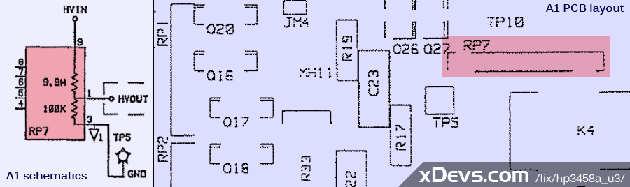
Image 26: Schematics and layout location of divider on HPAK 3458A A1 PCBA
Actual component on board does not reveal any visible damage, however looks can be deceiving.

Image 26: High voltage divider PR7 and K4 HV reed relay photo
Let’s replace this network and test again. As replacement I used same RP7 from another faulty A1 PCBA, so original schematics would be unchanged and performance tweaks for HV, if there are any, still work as they were designed in 3458A. I also replaced K4 relay which is involved in switching input signal to this RP7 divider, just in case. It’s customized to HP order high-voltage non-latching reed relay made by COTO, P/N 3500-0044. It’s hermetic low thermal EMF <10 µV , rated up to 1500 VDC isolation, with steel shielding and insulation resistance over 1012 Ω. This series relays are available today for some $20 USD/pcs.
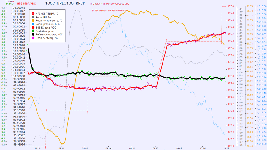
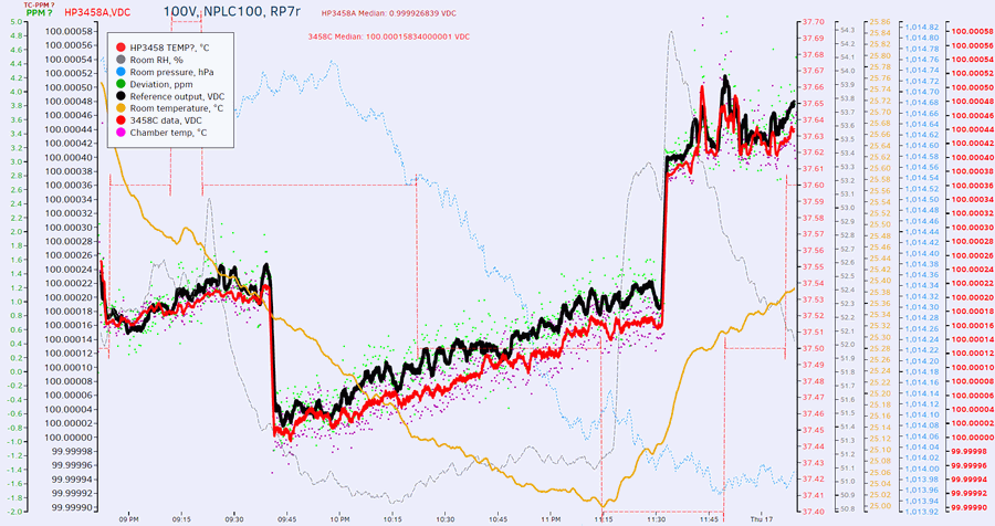
Image 27: Test after replacement of RP7 divider
Now drift is half of what we saw, about +1.06ppm/hour.
It will be interesting to test this divider tempco, as now we have it removed off the circuit. Perhaps a short experiment for later.
Also good off-shelf (yet not mechanically same) replacement for this divider network might be something like CADDOCK USVD2-B10M-010-02 which is same 9.9MΩ/100KΩ divider with ratio temperature coefficient ±2ppm/°C and price $62.77 USD, each.
Day 4: More debug on drift on 100V and 1000V range
Probed TP11 with regard to input LO and multiplied output with 100.007 math gain. Here’s the result:
Note that 100VAC range using 70VAC input does not have drift issue :). This happens due to different input signal path for used AC measurements. Graph below is AC frequency 1kHz, sourced from HP 3245A.
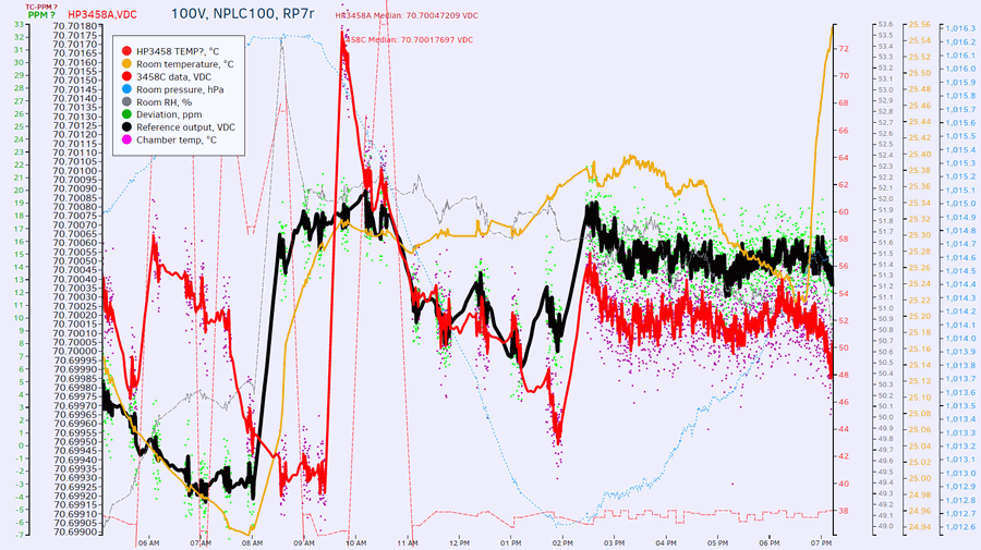
As side bonus, ACAL DCV procedure was captured on TP11 test point, using my own 3458A as sampler at NPLC 1 speed.
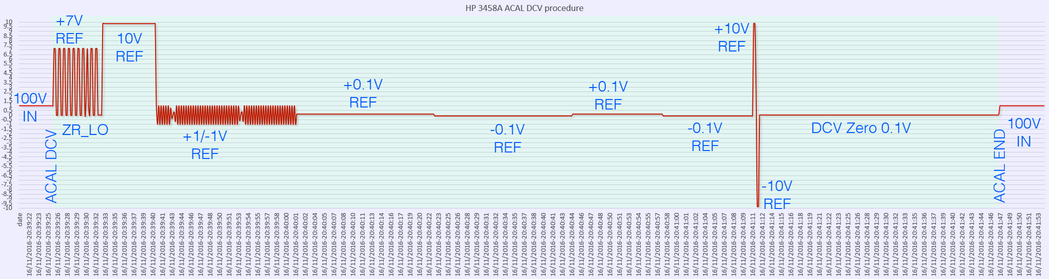
CSV-datalog of ACAL DCV, measured TP11 point on A1
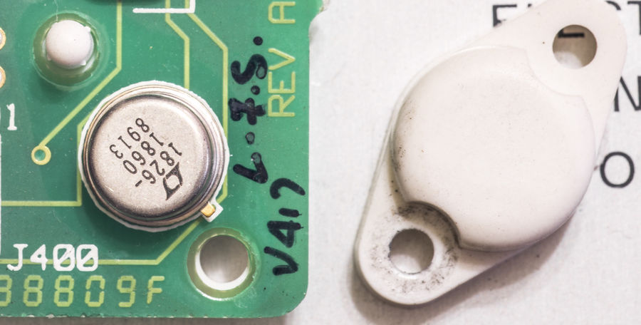
Bonus content: Photo of A9 reference used. Bottom cap side has funky arm to act as spacer.
Custom HP marking on Linear LTZ1000A.
Calibration
Zero calibration
Zero for both front and rear terminals was calibrated using our xDevs.com shorting plug with gold-plated jacks. Check on switch resistance revealed no problem, resistance reading was good, so original switch left on A11 without replacements.
DCV calibration
Meter was adjusted to our calibrated HP 3458A, using modified HP 3245A as a transfer standard. Transfer stability over half hour of this LTZ1000-upgraded generator, sourcing 10VDC was confirmed to stay better than 0.4 ppm, which is good enough even for 3458A-002 calibration.
Actual calibration before and after is visible on graph chart above. Unit was -2.3ppm away from our 3458A, and was adjusted to <0.4ppm by running CAL 10.000001,3458 command.
OHM calibration
Similar adjustment to our 3458A was done, using Vishay foil 10KΩ resistor CAL 9999.792,3458 command.
ACV flatness calibration
As I don’t have access to calibrated thermal converters, so this calibration was not performed. It’s affecting likely only >1MHz AC measurements, as calibration is done on 2MHz and 8MHz points.
Summary
Overall, it was good outcome, given time slot of just ~50 hours to work on the unit. Meter is back to owner already, happily measuring check +10 VDC output of calibrator (calibrated back in 2011!) with <1 ppm accuracy.
Project cost:
| Item | Cost | Shipping | Supplier |
|---|---|---|---|
| Parts replacement on A2 PCBA | N/A | N/A | Digikey |
| Dallas/MAXIM NVRAMs 1 x DS1220, 6 x DS1230 | 175$ | N/A | Maxim |
Table X: Replacement parts order
| Date | Activity | Time spent |
|---|---|---|
| 11/07/2016 | Received unit, initial teardown and repair | 7 hour |
| 11/08/2016 | NVRAM replacement and A5 firmware upgrade | 5 hour |
Modified: Nov. 23, 2016, 9:40 a.m.
References
- xDevs.com : HP 3458A restoration project worklog
- xDevs.com : Tale of the little jumper, or sharks in voltage references world
- EEVBlog : HP3458A Schaffner mains line filter failure
- TL866 minipro programmer page
- LT : LTZ1000 - Ultra Precision Reference
- Keysight product page : 3458A Digital Multimeter, 8½ Digit
- EEVBlog forum : Repair log, Old rusty HP 3458A
- EEVBlog : HP3458A input relays discussion
- EEVBlog : HP3458A Schaffner mains line filter failure
- HP 3458A CLIP