This is unfinished article draft.
Contents
Intro
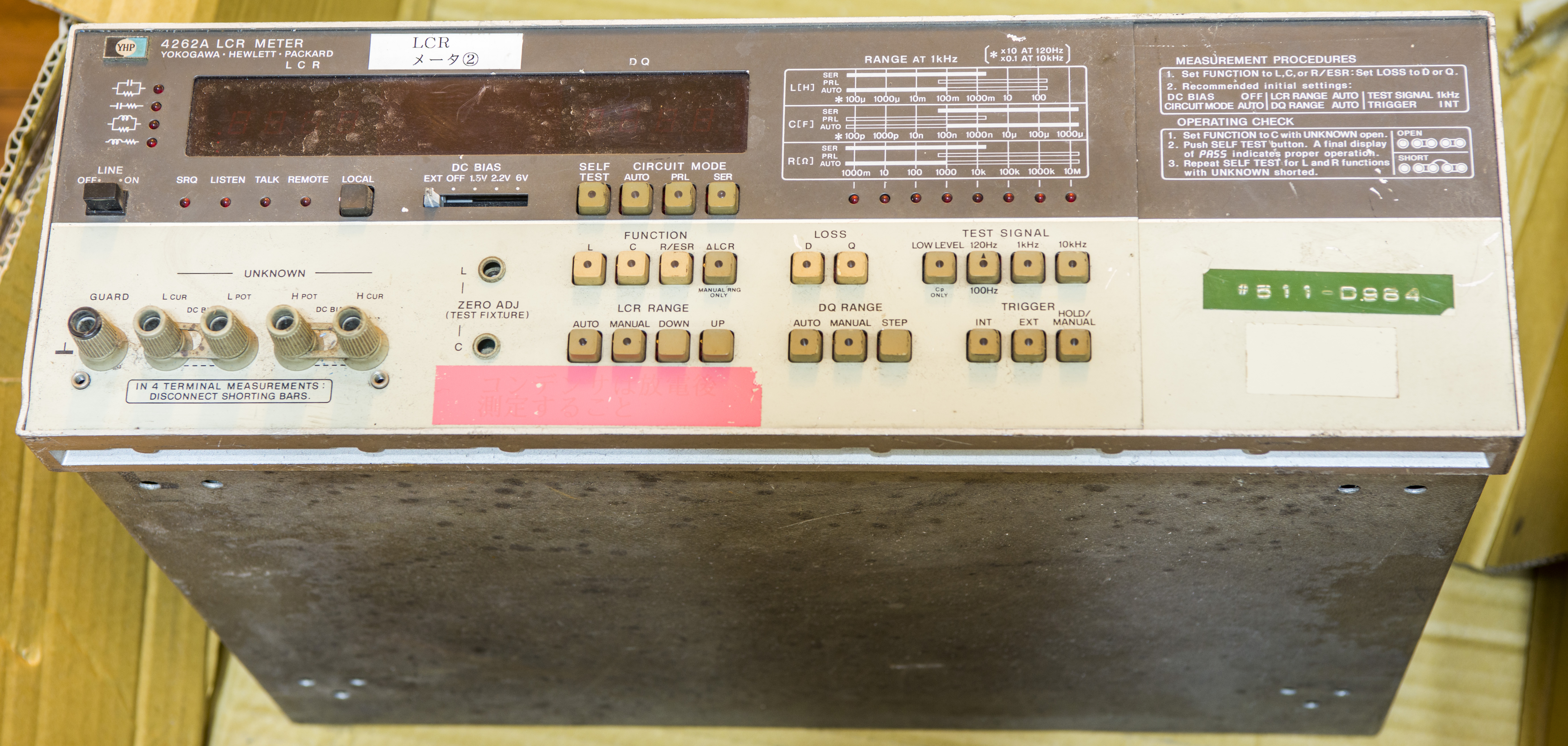
This old HP 4262A LCR meter is designed to measure parameters of components with good accuracy and speed. It is able to measure capacitance, inductance, resistance (ESR) and dissipation factor or quality factor over range of test frequencies 120Hz, 1kHz and 10kHz. Test device can be connected to meter via five-terminal port.
| Specification | Rated value | Units |
|---|---|---|
| Capacitance range | 0.01p to 19.9m | F |
| Inductance range | 0.01µ to 1999 | H |
| Resistance range | 1m to 19.9M | Ω |
| Basic accuracy | 0.2 – 0.3 | % |
| Measurement speed | 220 – 260 | ms |
| Display resolution | 3½ | digits |
| Range modes | Auto and manual | |
| Measurement frequency | 120(100), 1k, 10k | Hz, ±3% |
| Test signal level | 1.0 or 0.05 (CP) | VRMS |
| Warm-up time | 15 | minutes |
| Internal DC Bias | 1.5, 2.2, 6 | VDC, ±5% |
| External DC Bias | +40 maximum | VDC |
| Weight | ~ 8 | kg |
We already reviewed and repaired newer LCR HP 4263B, so this will be interesting to see legacy instrument, in respect of previous design concepts and technology.
There are also different options for 4262A, such as:
| Option | Description | ||||||
|---|---|---|---|---|---|---|---|
| 001 | BCD and DQ data output interface | ||||||
| 004 | Digital comparator to provide HIGH/IN/LOW signal for ATE purpose | ||||||
| 101 | HP-IB (GPIB) interface. Cannot be used together with Opt.004 | ||||||
| 010 | 100 Hz test frequency instead of 120 Hz | |
907 | Front handle kit | |
908 | Rackmount flange |
| 909 | Both kits from 907 and 908 | ||||||
| 910 | Extra manual kit |
Table 2: 4262A options and versions
Disclaimer
Redistribution and use of this article or any images or files referenced in it, in source and binary forms, with or without modification, are permitted provided that the following conditions are met:
- Redistributions of article must retain the above copyright notice, this list of conditions, link to this page (/fix/hp4262a/) and the following disclaimer.
- Redistributions of files in binary form must reproduce the above copyright notice, this list of conditions, link to this page (/fix/hp4262a/), and the following disclaimer in the documentation and/or other materials provided with the distribution, for example Readme file.
All information posted here is hosted just for education purposes and provided AS IS. In no event shall the author, xDevs.com site, or any other 3rd party, including HP/Agilent/Keysight Technologies be liable for any special, direct, indirect, or consequential damages or any damages whatsoever resulting from loss of use, data or profits, whether in an action of contract, negligence or other tortuous action, arising out of or in connection with the use or performance of information published here.
If you willing to contribute or add your experience regarding HP/Agilent/Keysight instruments repairs or provide extra information, you can do so following these simple instructions
Documents
As often with old HP instruments, full operation and service manual are available, featuring theory of operation, full component level BOMs, schematics and boards layout drawings. All that will come handy during diagnostics and repair.
Model 4262A LCR Performance Test section 4 manual
Exterior
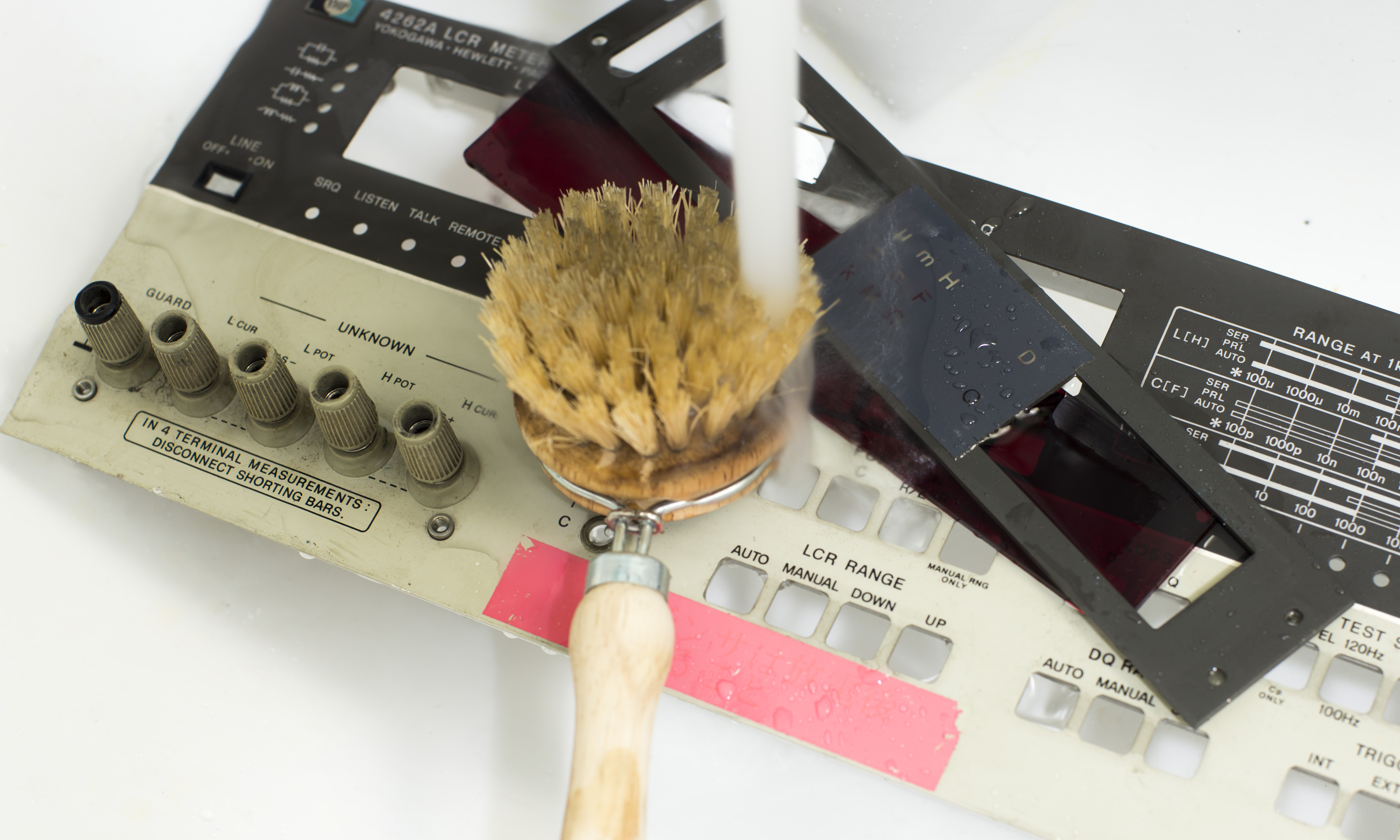
Meter is extremely dirty and require great lot of cleaning. Input connector binding posts are rusty and covered in spider webs. It’s sad to see such instruments treated like this.
Diagnostics
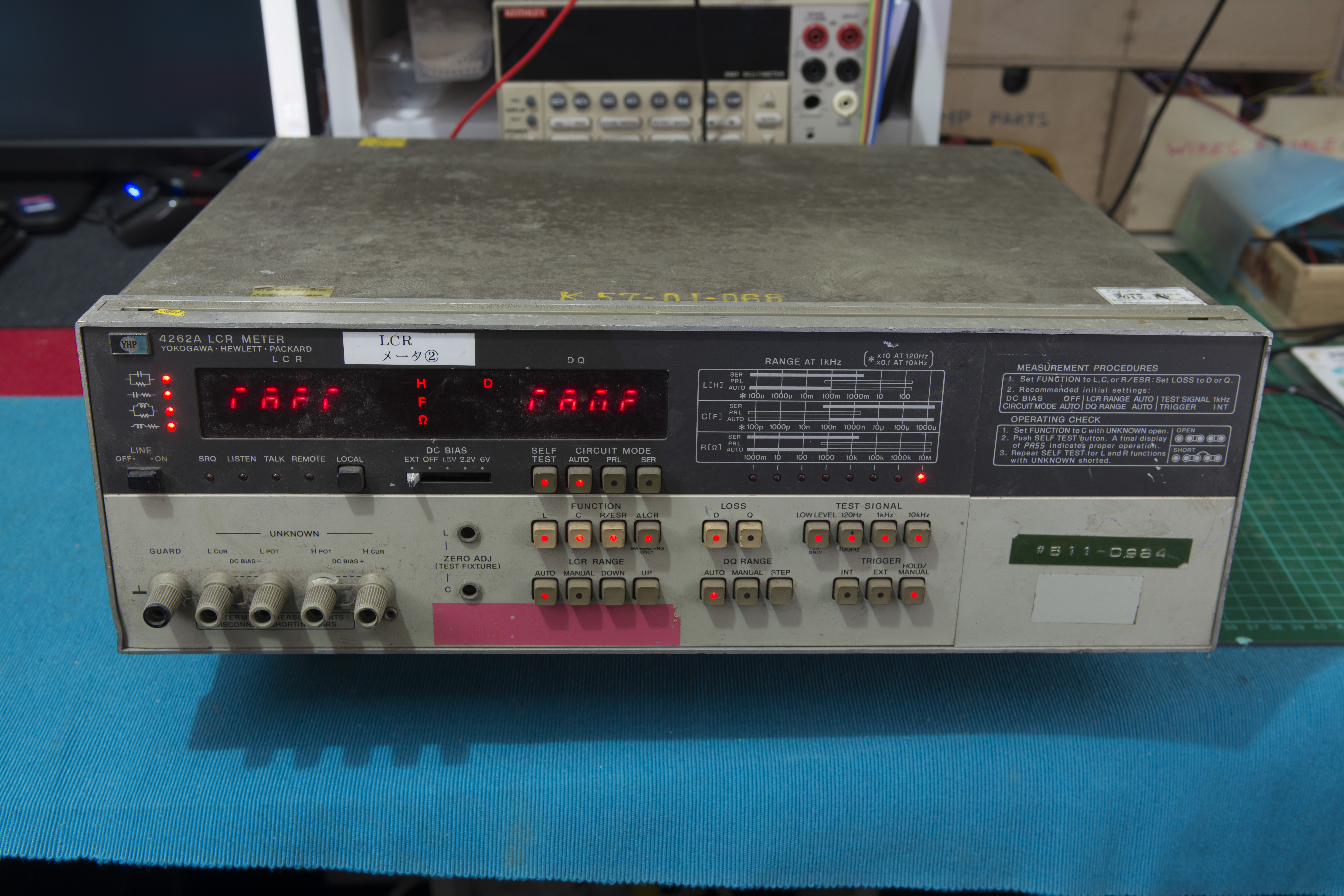
On power on LCR just show random garble on displays and random key LEDs lit. No reaction to any button press as well. Sounds like digital controller issue.
Initial checks quickly revealed absence of negative -12V supply. And because of that there are no negative bias voltage available to processor, which prevents digital controller to work. Usual approach to diagnose and repair power supply issues first pays off once again. It’s very good rule to start with visual inspection and DMM checks on unknown condition instrument, starting with power supply circuits.
Measured power supply output voltages:
| Test point | Expected voltage | Measured voltage | Result |
|---|---|---|---|
| +12V on A9 PCB | +11.95 … +12.05 VDC | +11.9935 VDC | PASS |
| +5V on A9 PCB | +4.85 … +5.15 VDC | +4.9955 VDC | PASS |
| -12V on A9 PCB | -11.85 … -12.15 VDC | +0.188 VDC | FAIL |
| -5V on TP4 CPU board | -4.9 to -5.1 VDC | +0.058 VDC | FAIL |
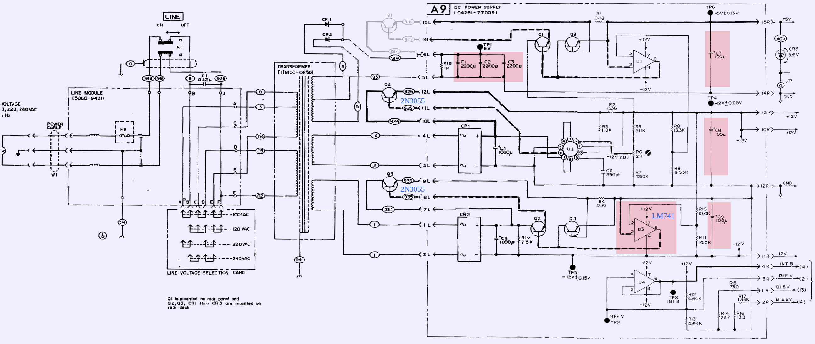
Power supply schematics:
Due to OCR quality of old manual, reference designators and signal names are barely readable, but it’s not complete showstopper right now. Power supply is rather common design, using linear transformer to convert mains into low voltages, diode bridges to rectify secondary output and linear regulators to provide stable output voltages.
Negative 12V supply is using opamp and tracking circuit with two 10 KΩ resistors to follow +12V supply output.
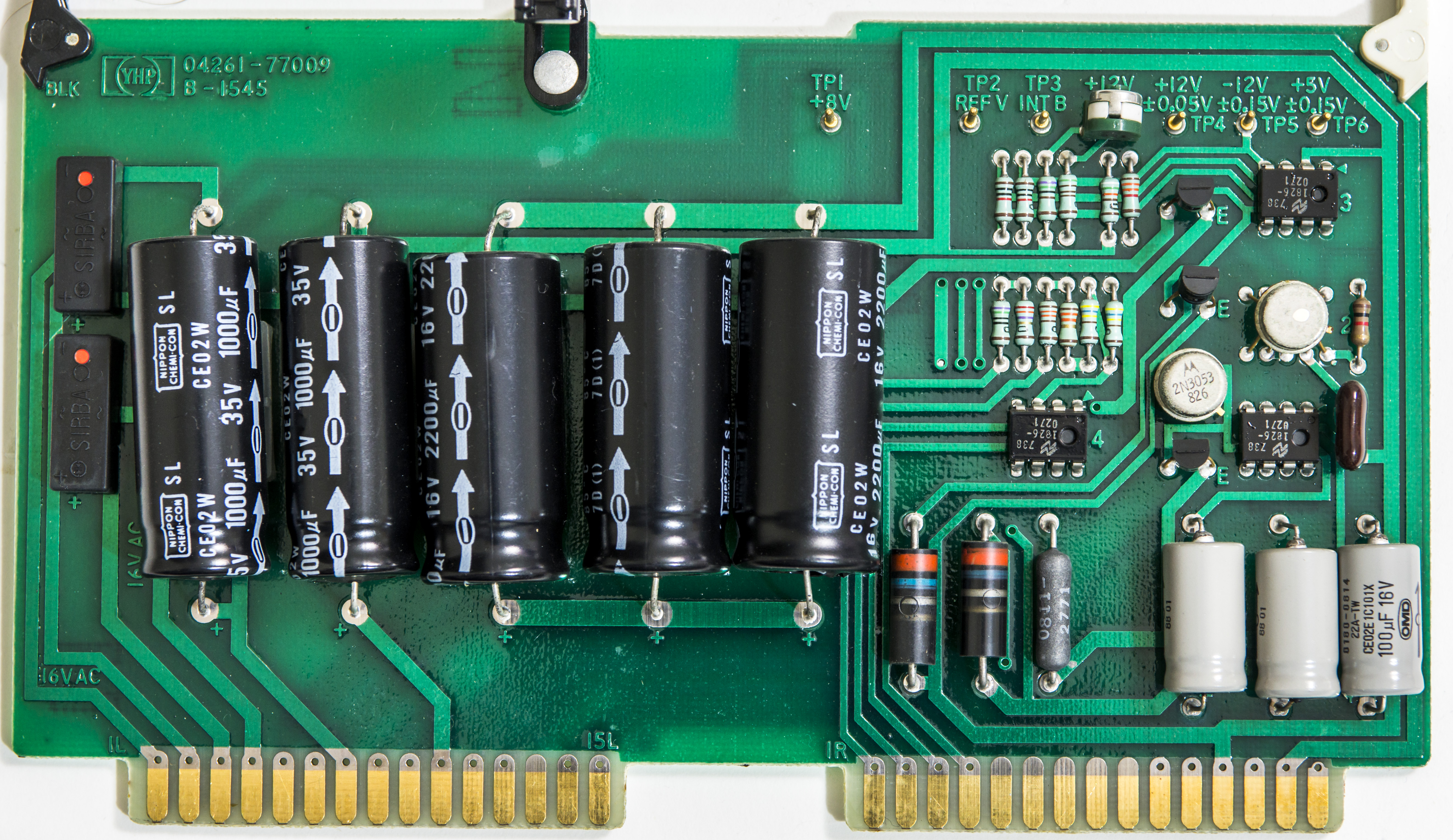
Checking voltage across C5 capacitor shown good +23 VDC, so rectifier and transformer work fine at this point.
Interior
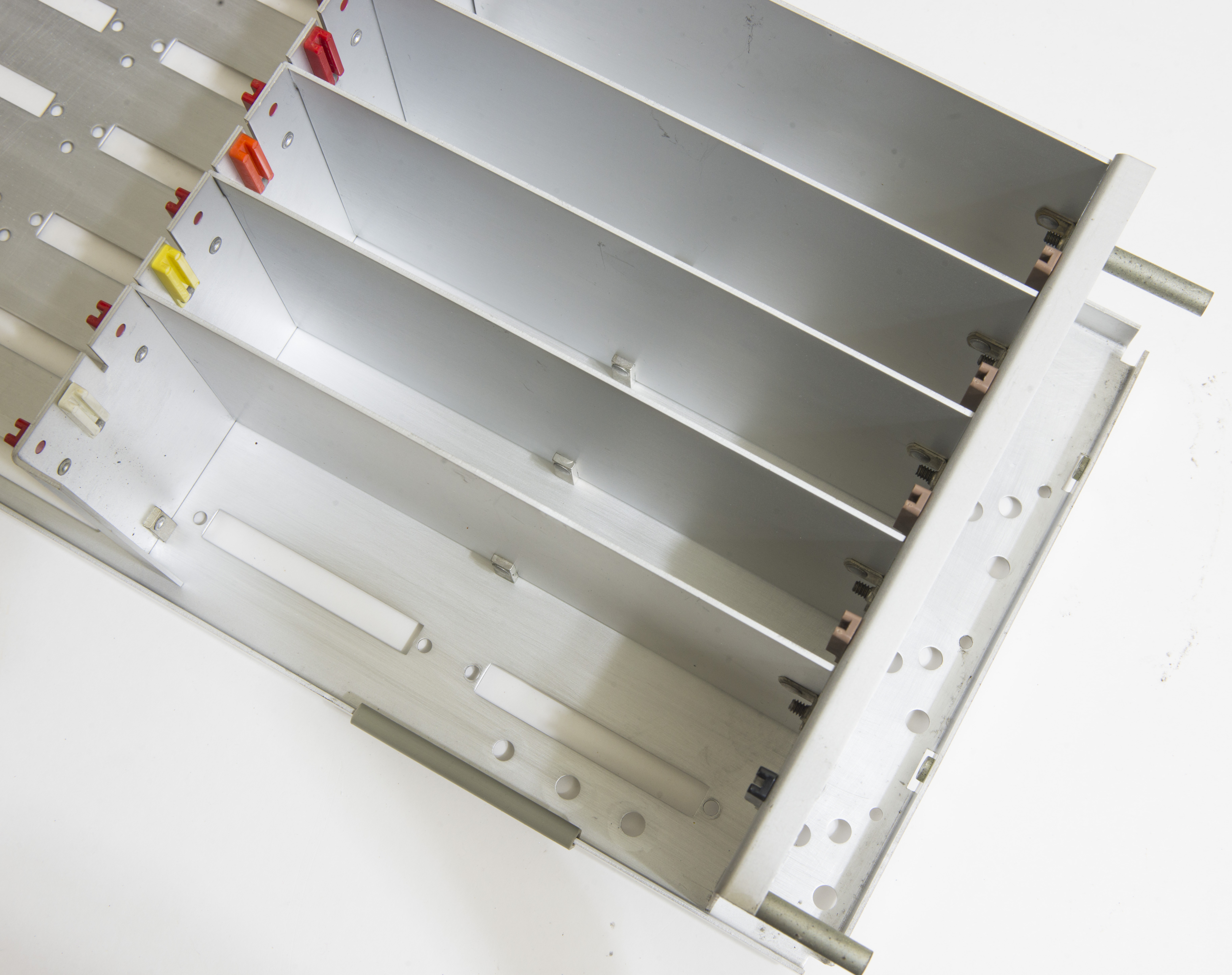
Removal of top cover revealed easy and convinient access to inner modules and PCB cards:

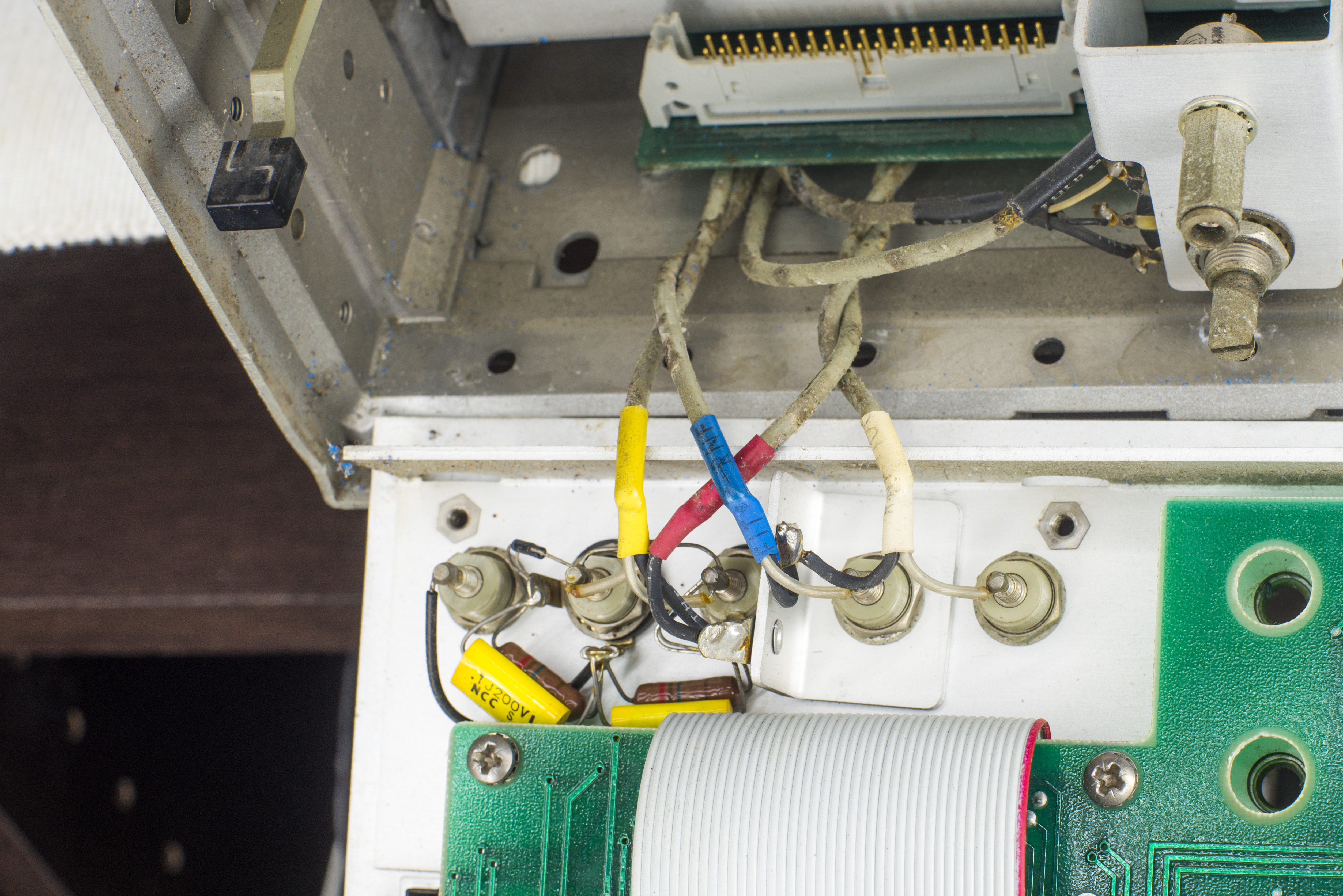
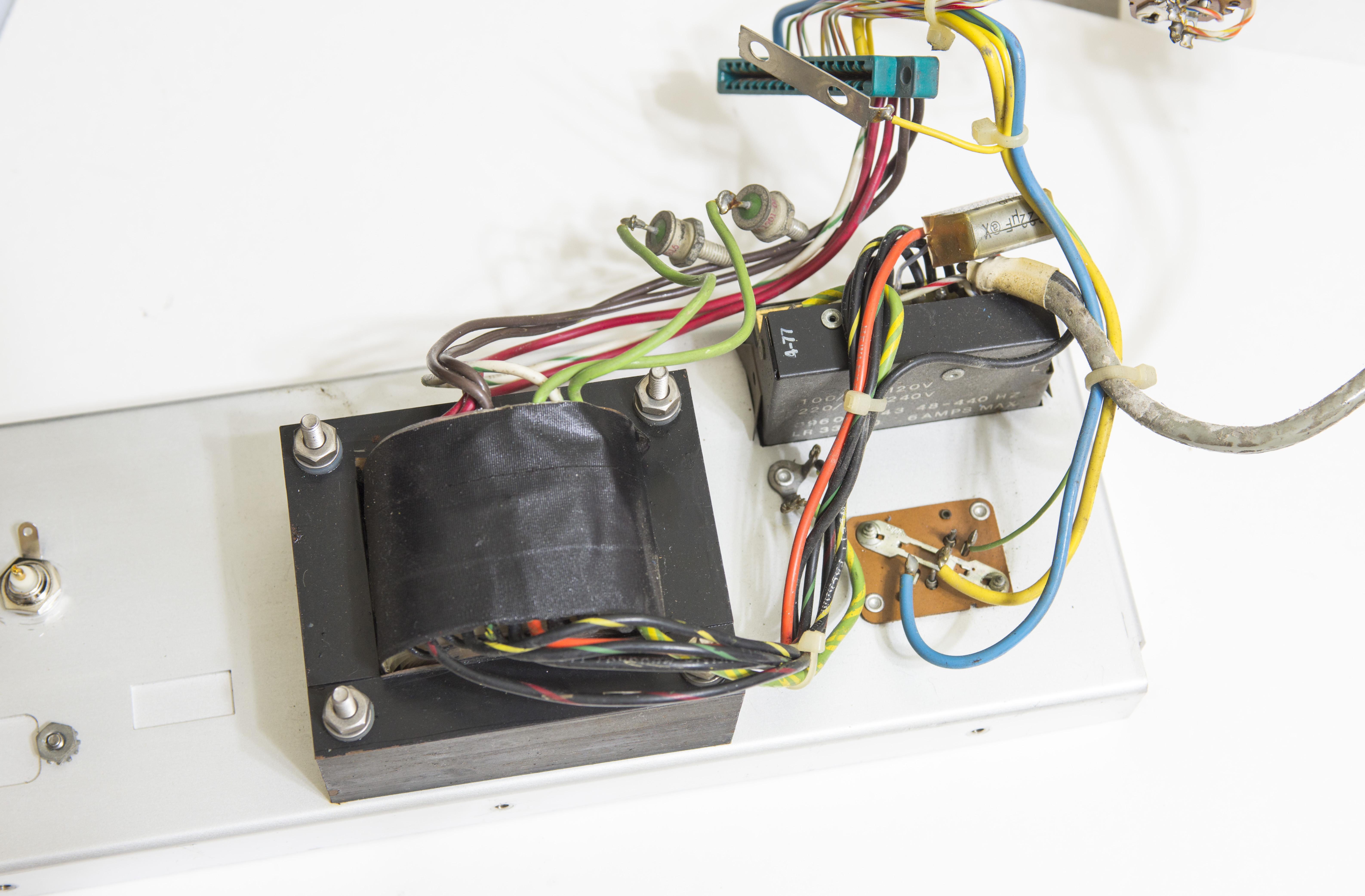
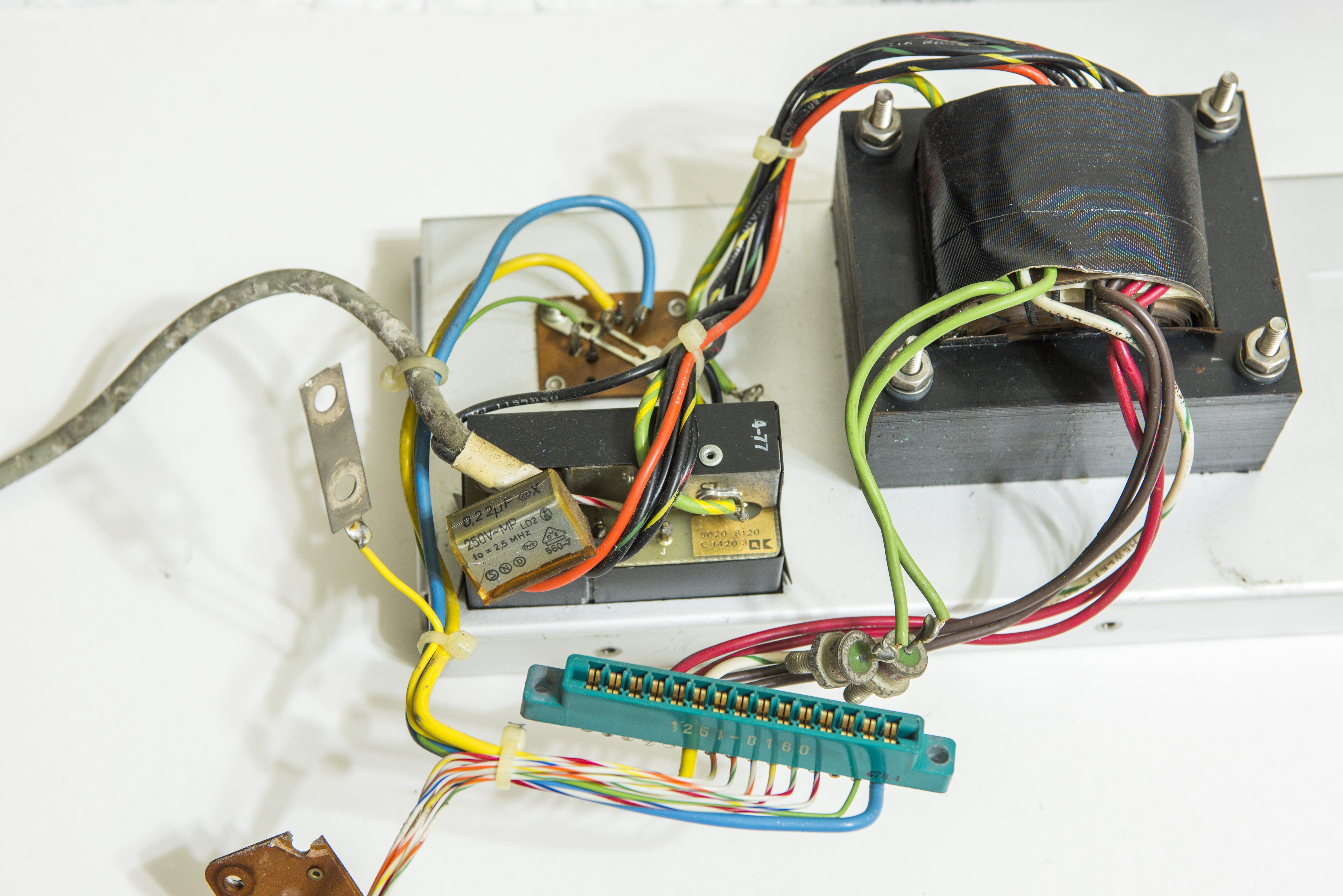
Some of the power supply components are mounted on inner chassis frame, such as transistors Q2 and Q3 in large TO-3 package, and rectifier diodes after primary transformer.
Diodes CR1 and CR2 are bolted down to chassis with metal washers with non-conductive plating. Make sure those are isolated from grounded chassis frame, or you may damage the transformer secondary! Cathodes of both diodes are connected to provide power output for A9 Power supply PCBA.
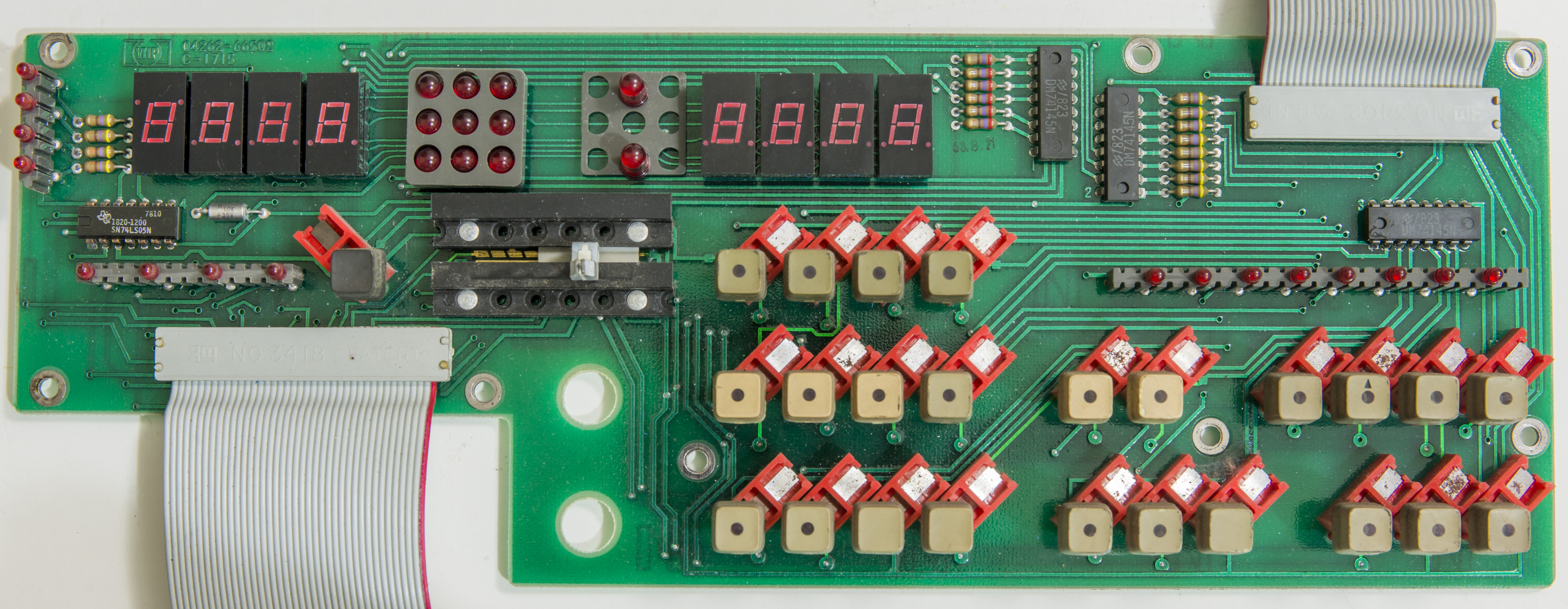
A2 Keyboard and Display PCBA

A9 Power supply PCBA

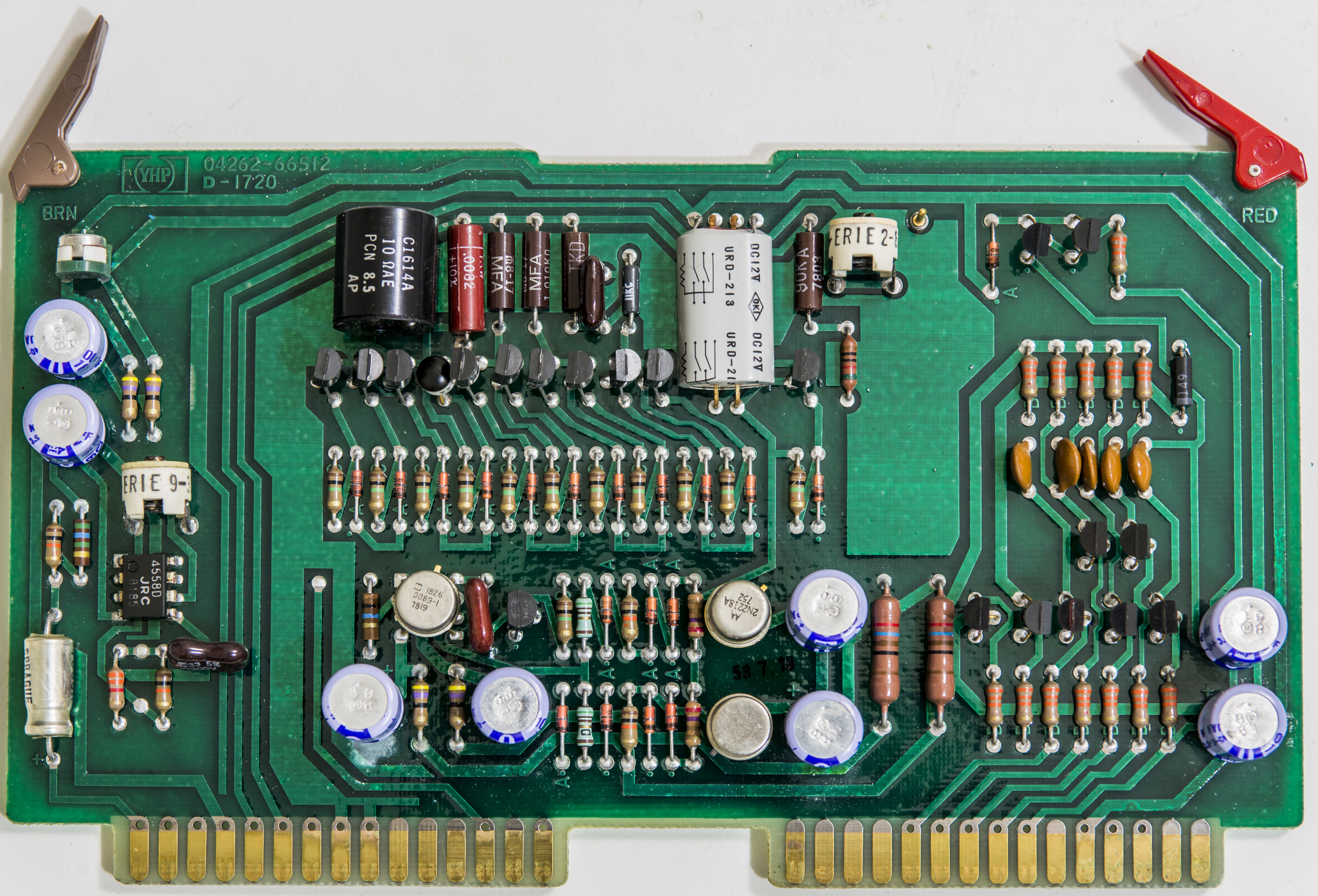
A11 Oscillator and Source resistor PCBA
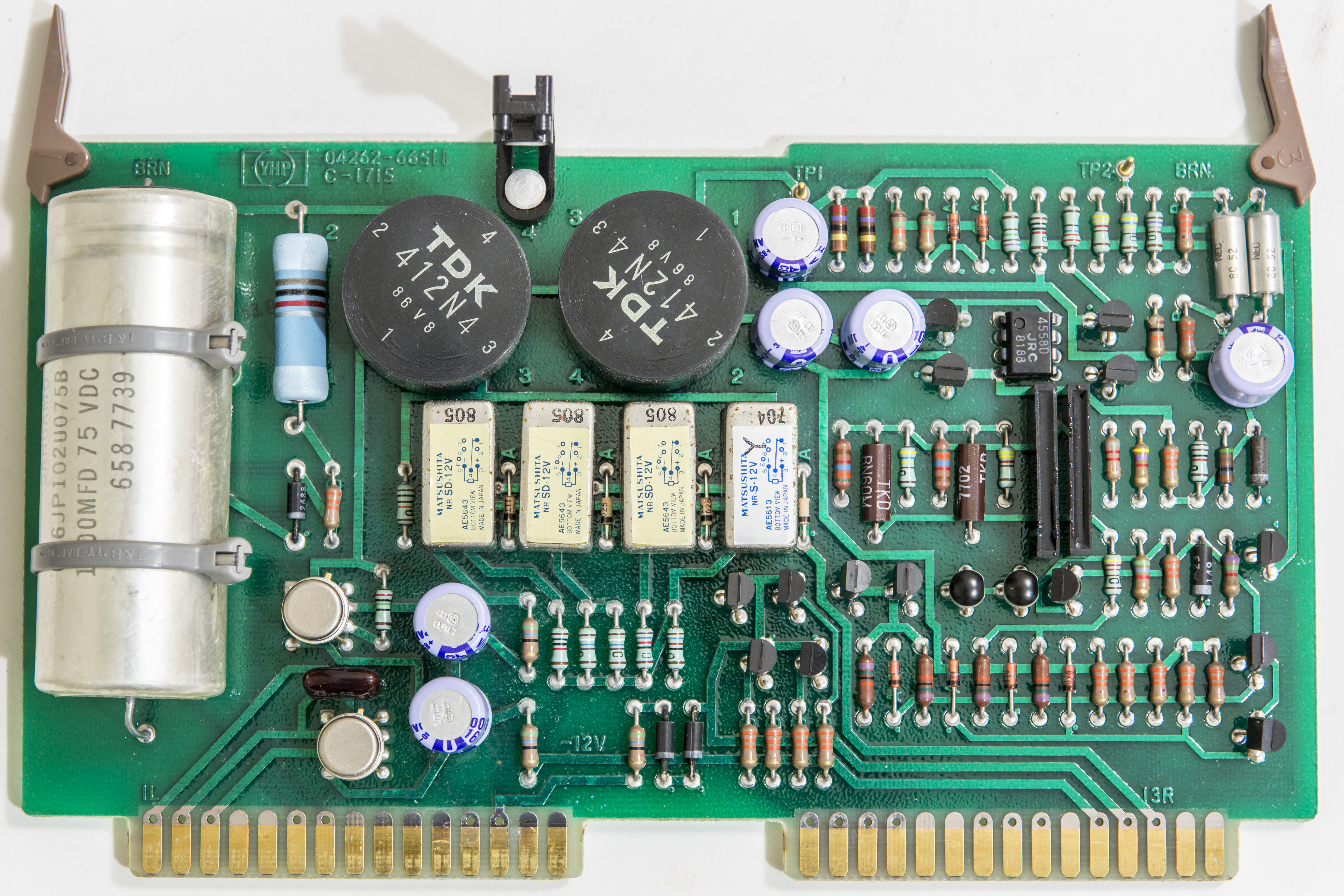
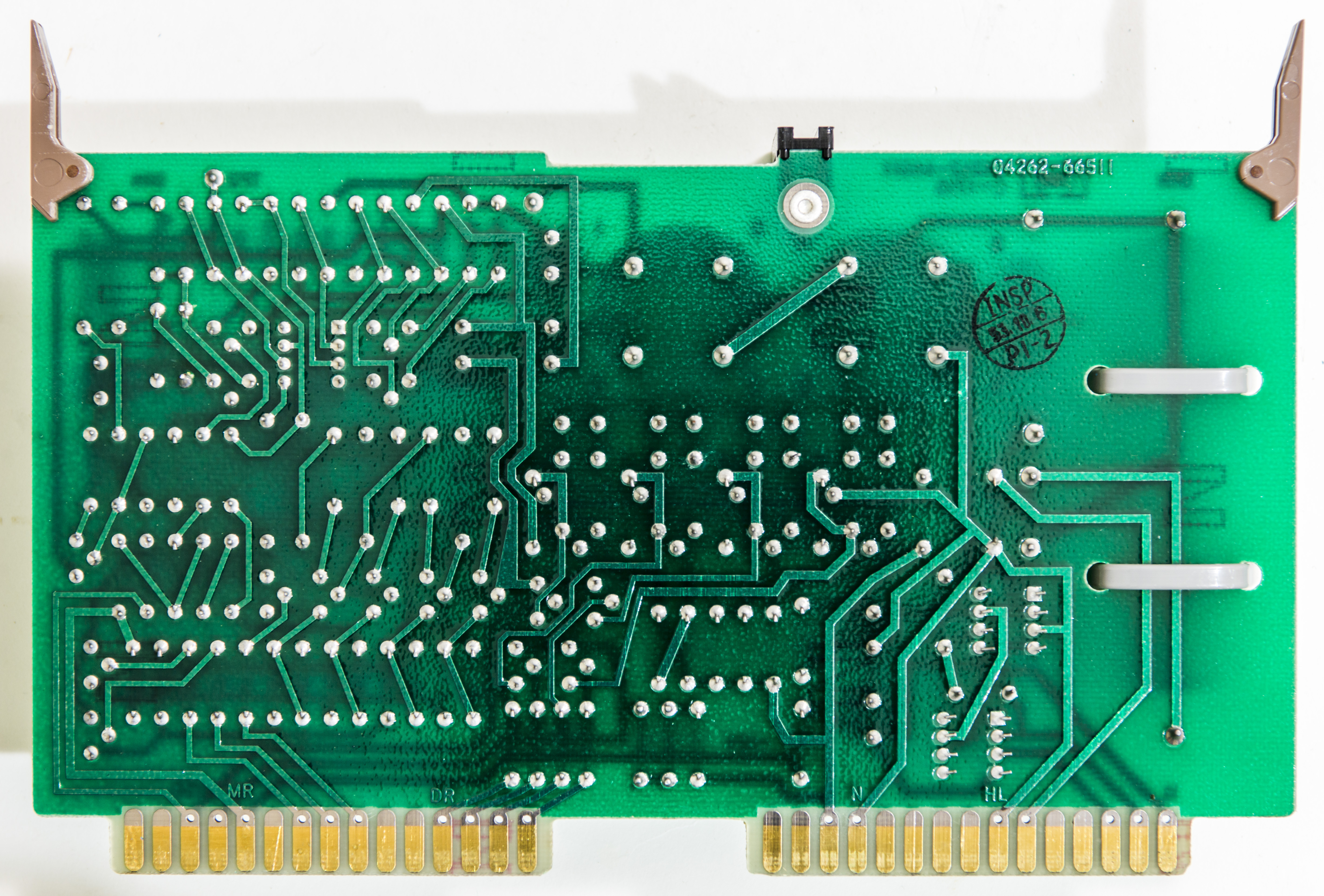
A12 Range Resistor PCBA
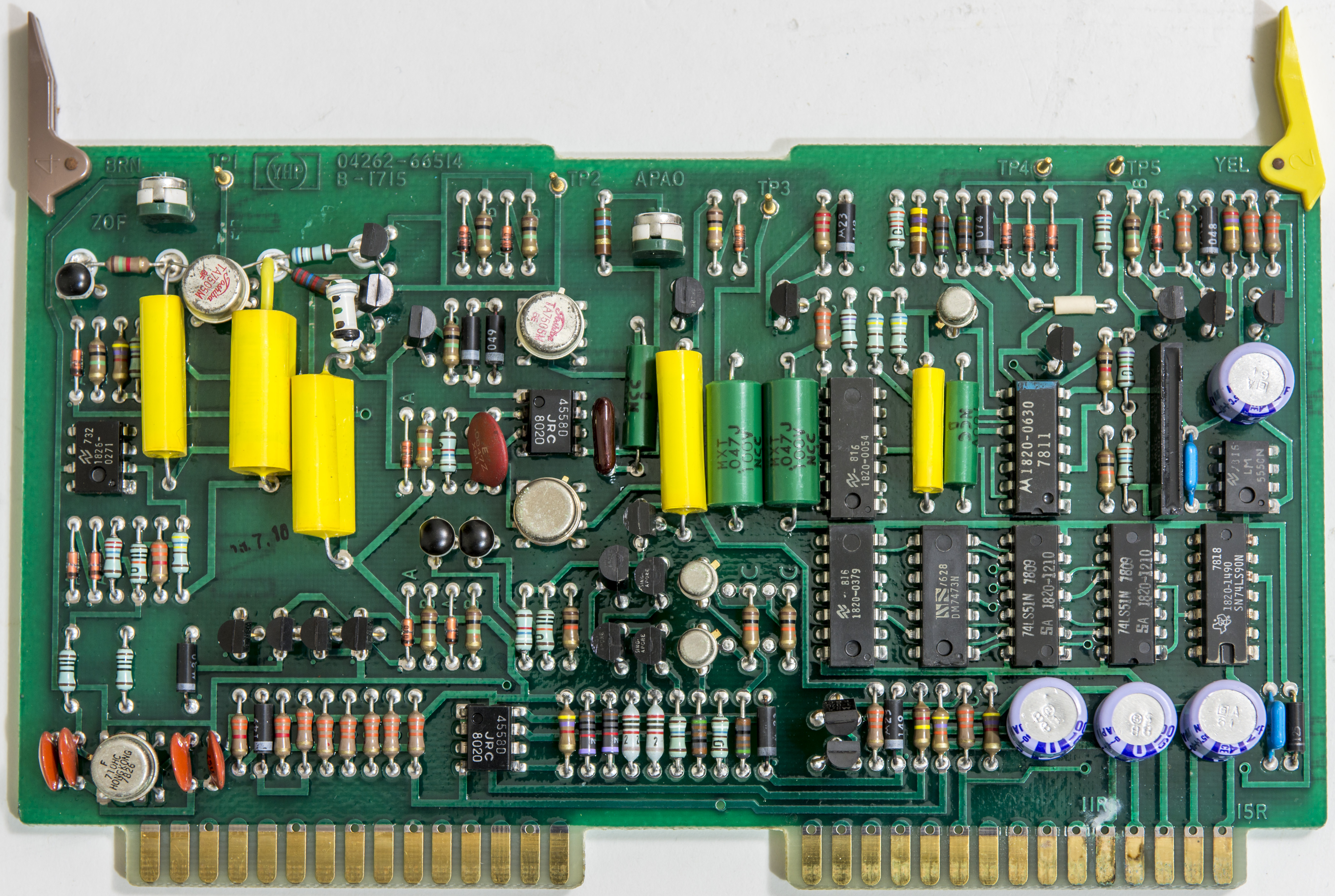
A13 Process Amplifier PCBA

A14 Phase Detector and Integrator PCBA
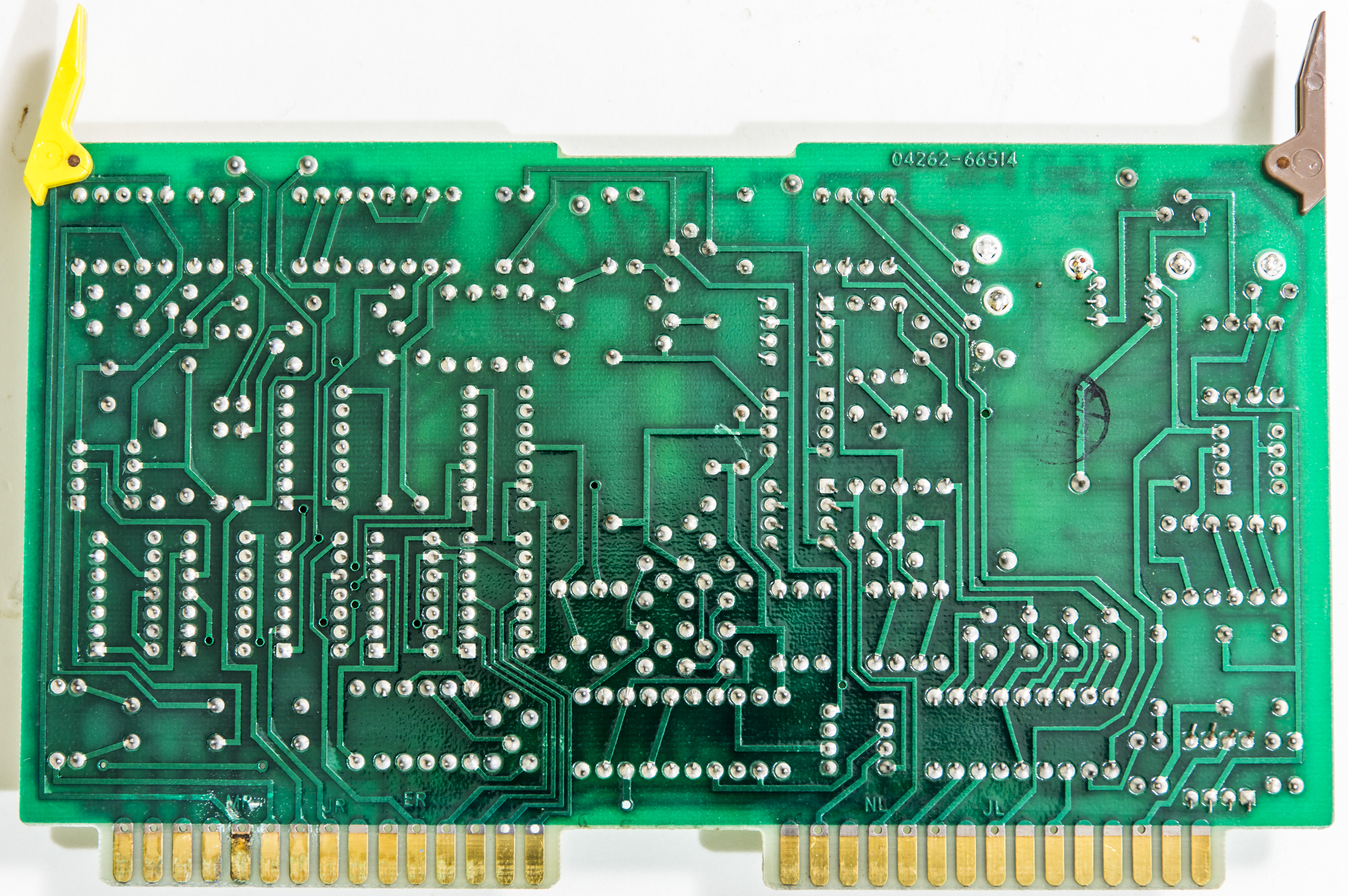
A21 Keyboard controller PCBA

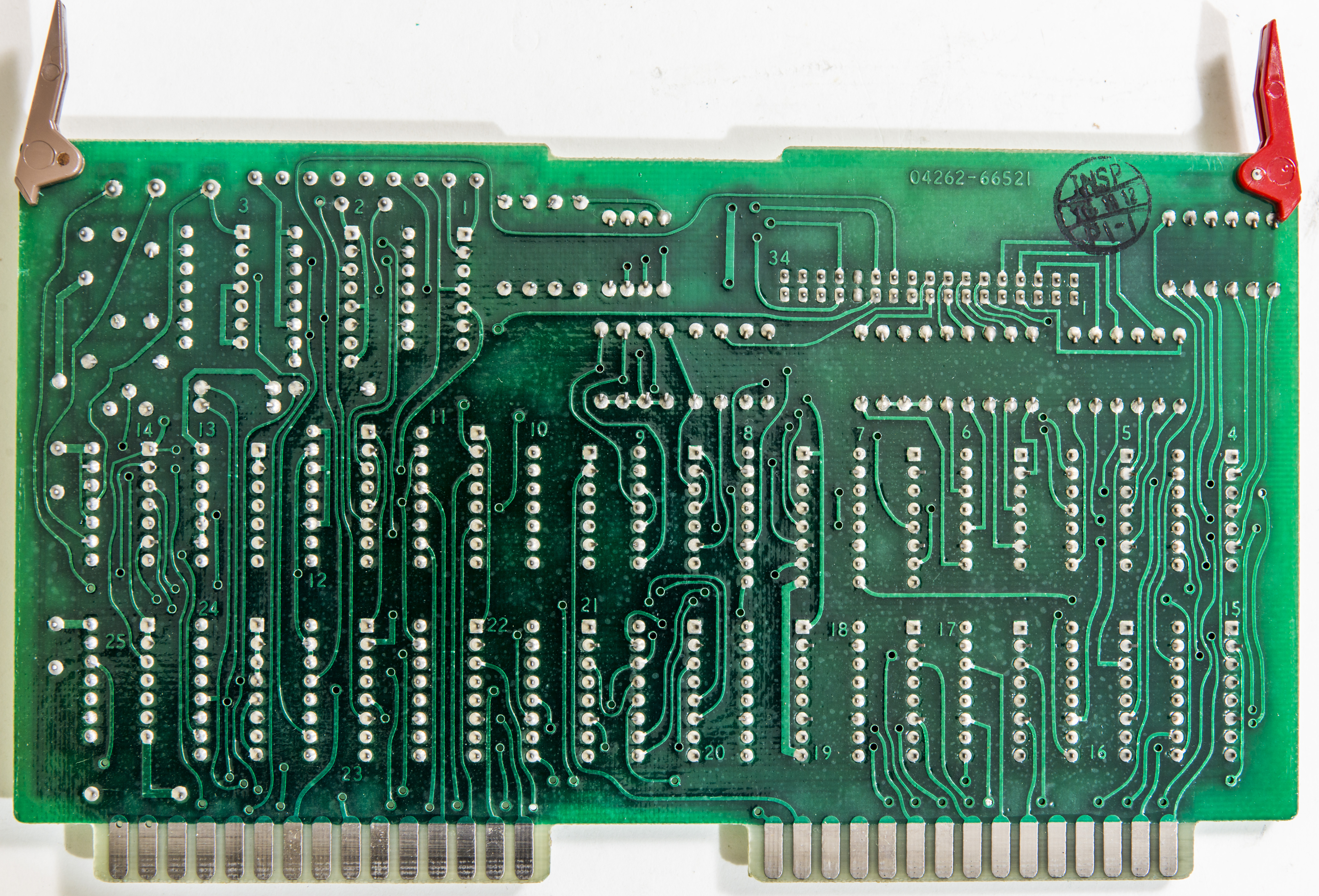
A22 Display Controller and RAM PCBA
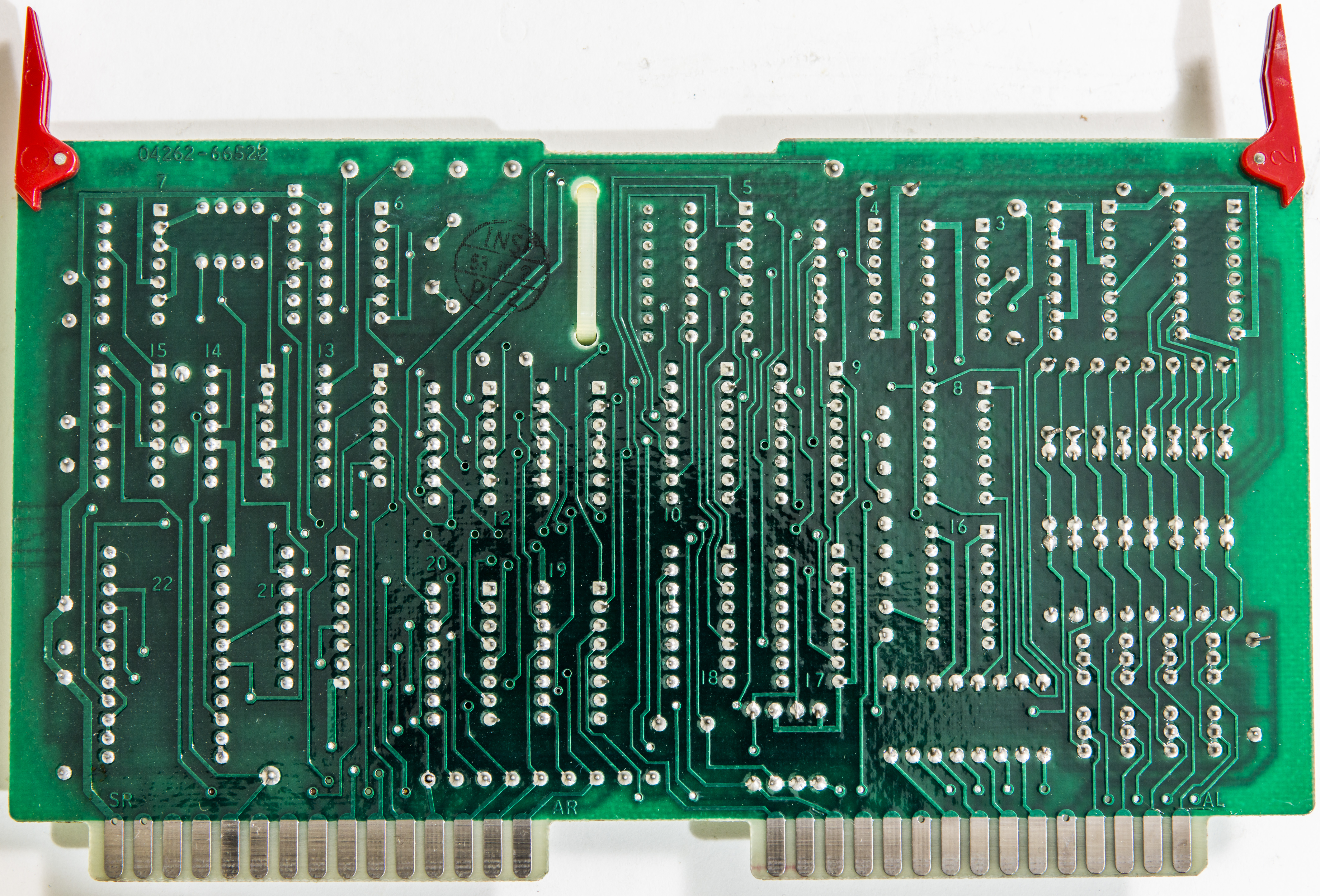
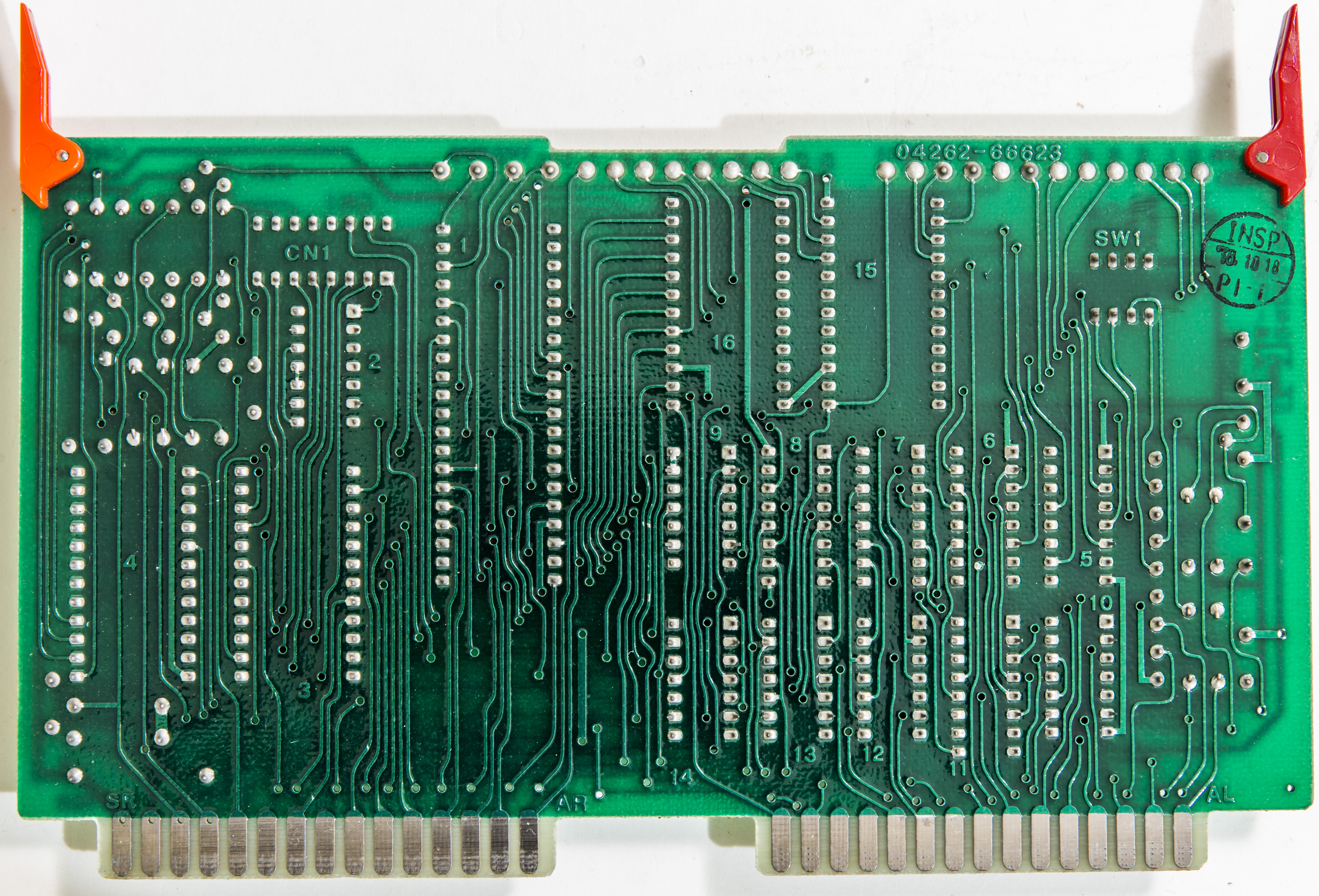
A23 Processor and ROM PCBA
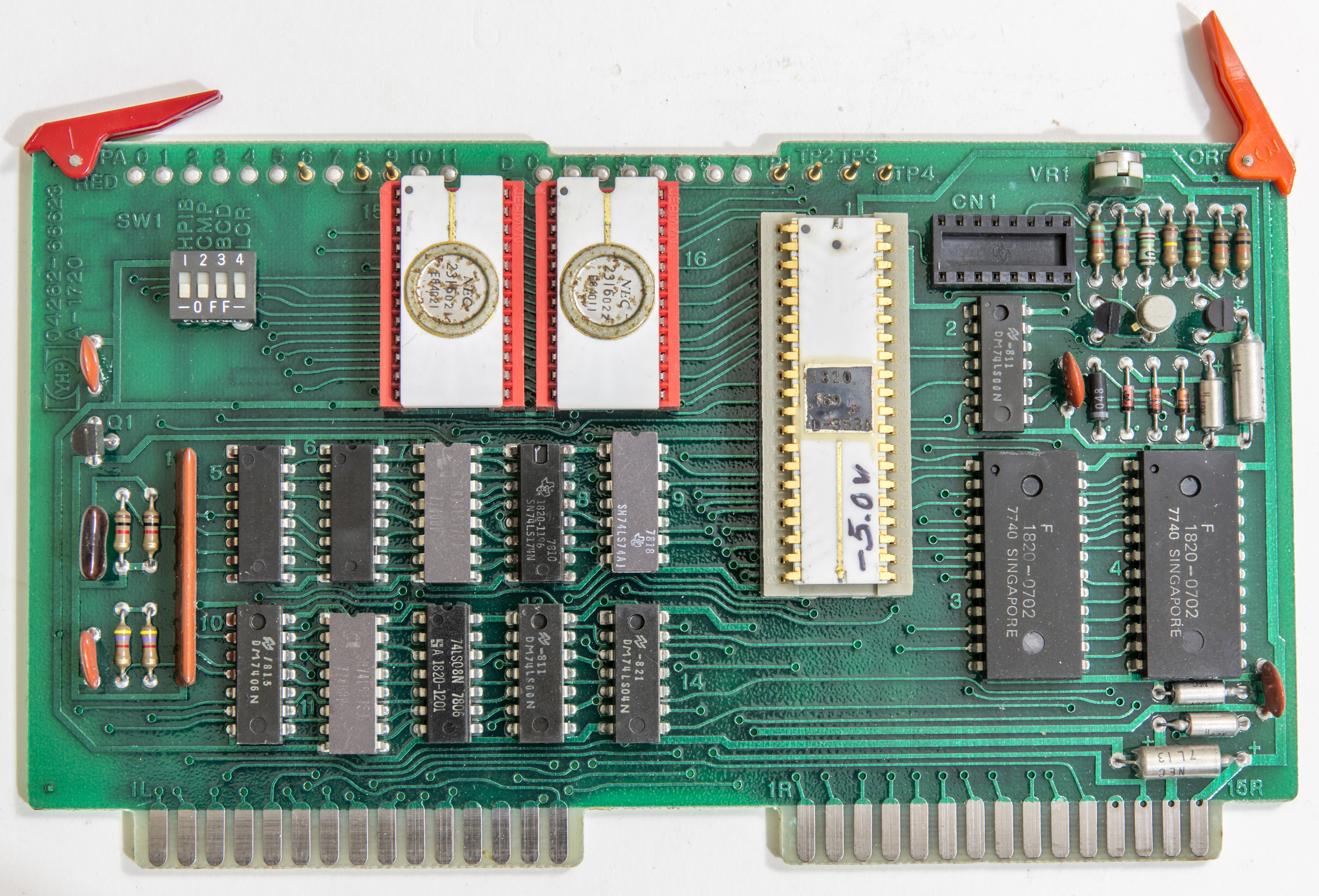
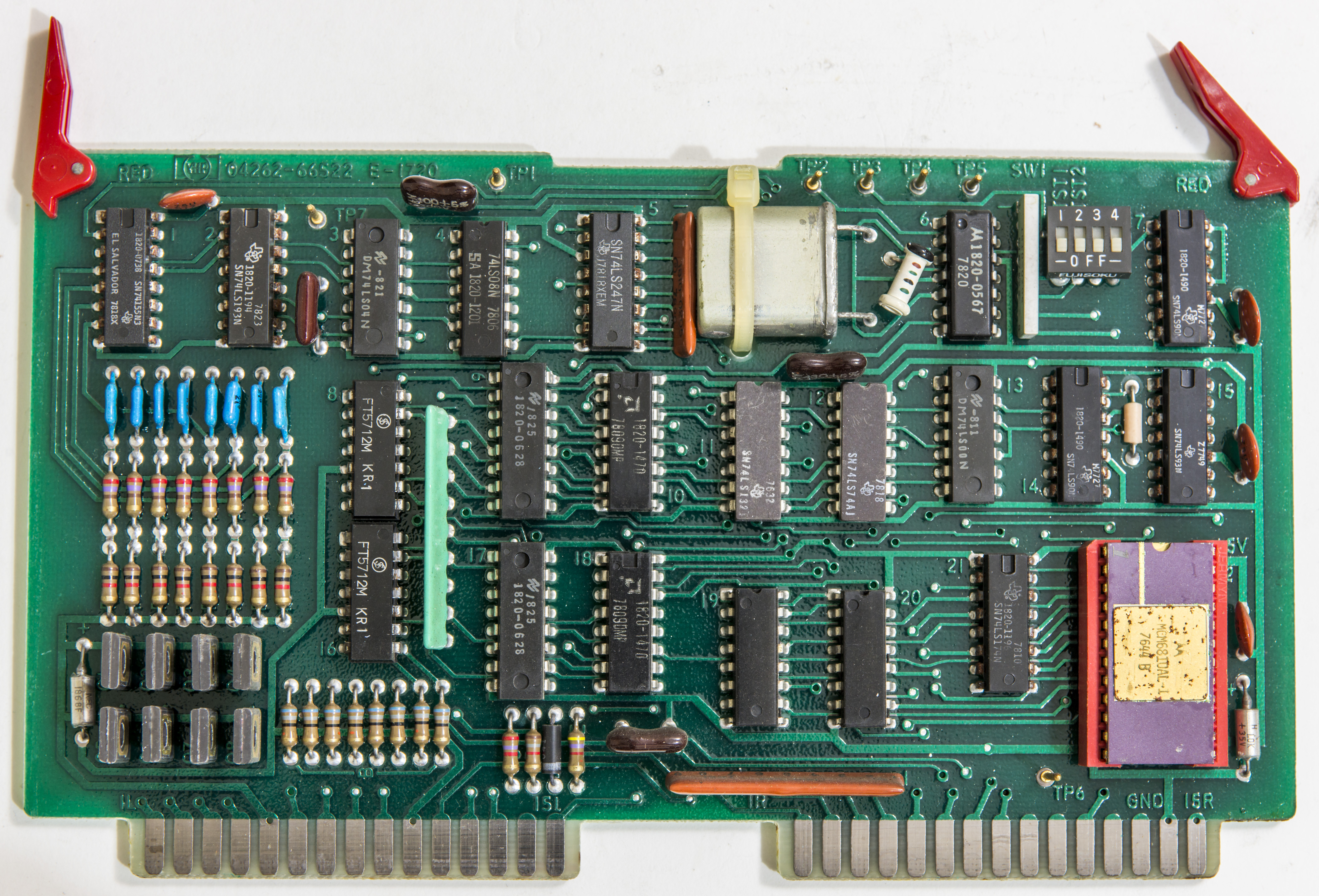
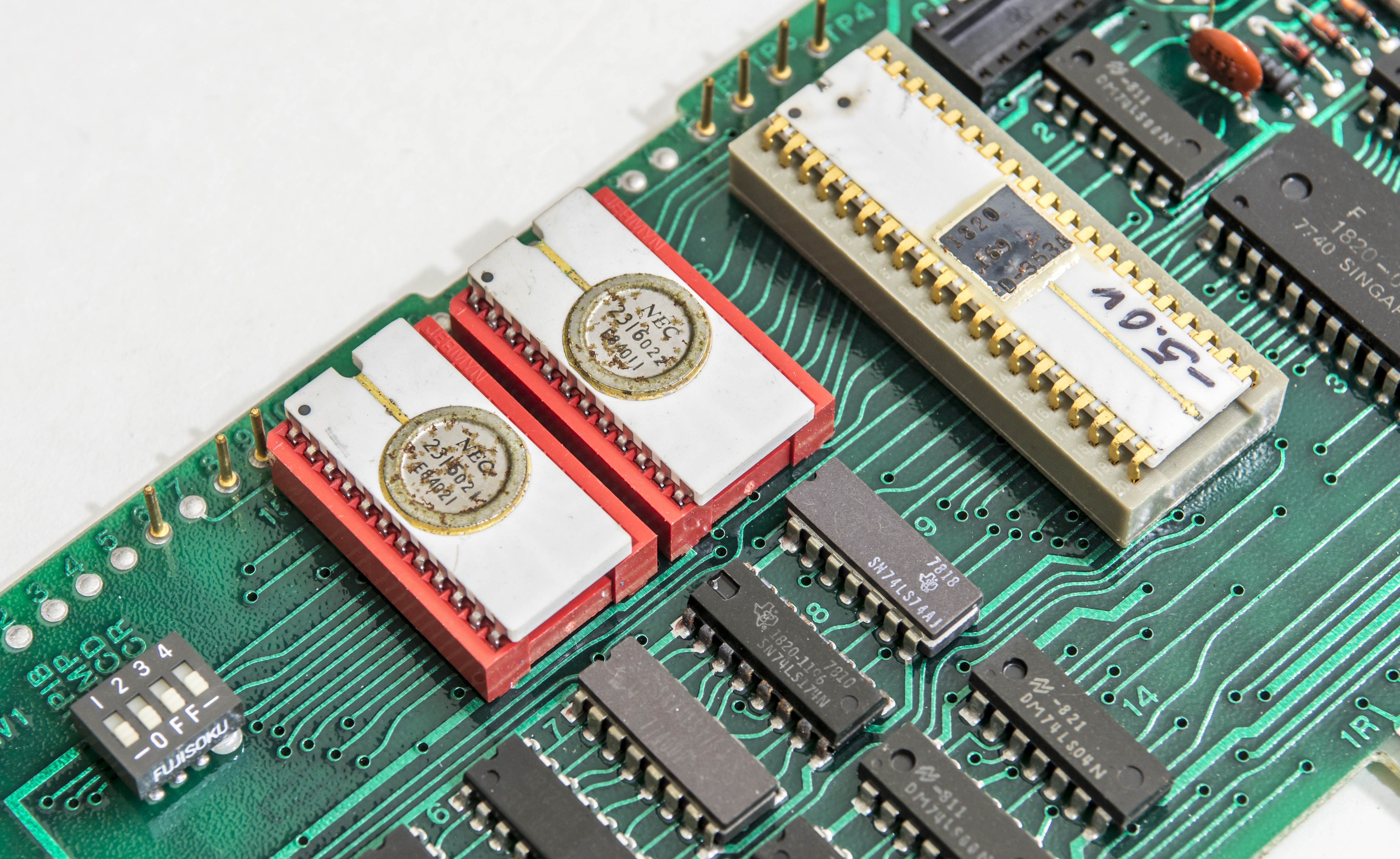
This instrument is using unique Nanoprocessor designed by HP Loveland Instrument Division using NMOS process. It’s an 8-bit processor optimized for instrument control. It has an 11 bit program counter, one 8 bit accumulator and 16 8-bit storage registers with a grand total of 42 instructions. This processor used in a number of instruments and GPIB controllers by HP.
In addition to the 4262A, they also used it in the 3225A function generator, among others. It could directly access 2KB of memory and up to 500KB with bank switching. Thanks to PaulAm EEVblog member for hints and information!.
That negative voltage hand-written on the chip is the backgate DC bias and varied from -2.0 to -5.0VDC. It varies from chip to chip sample. Factory cost was under $27 with an ALU and under $20 without it.
Repair
Cables to test ports are all covered in nasty fungus and require replacement.
Front panel fully disassembled and washed intensively in hot soapy water with considerable amount of brushing:
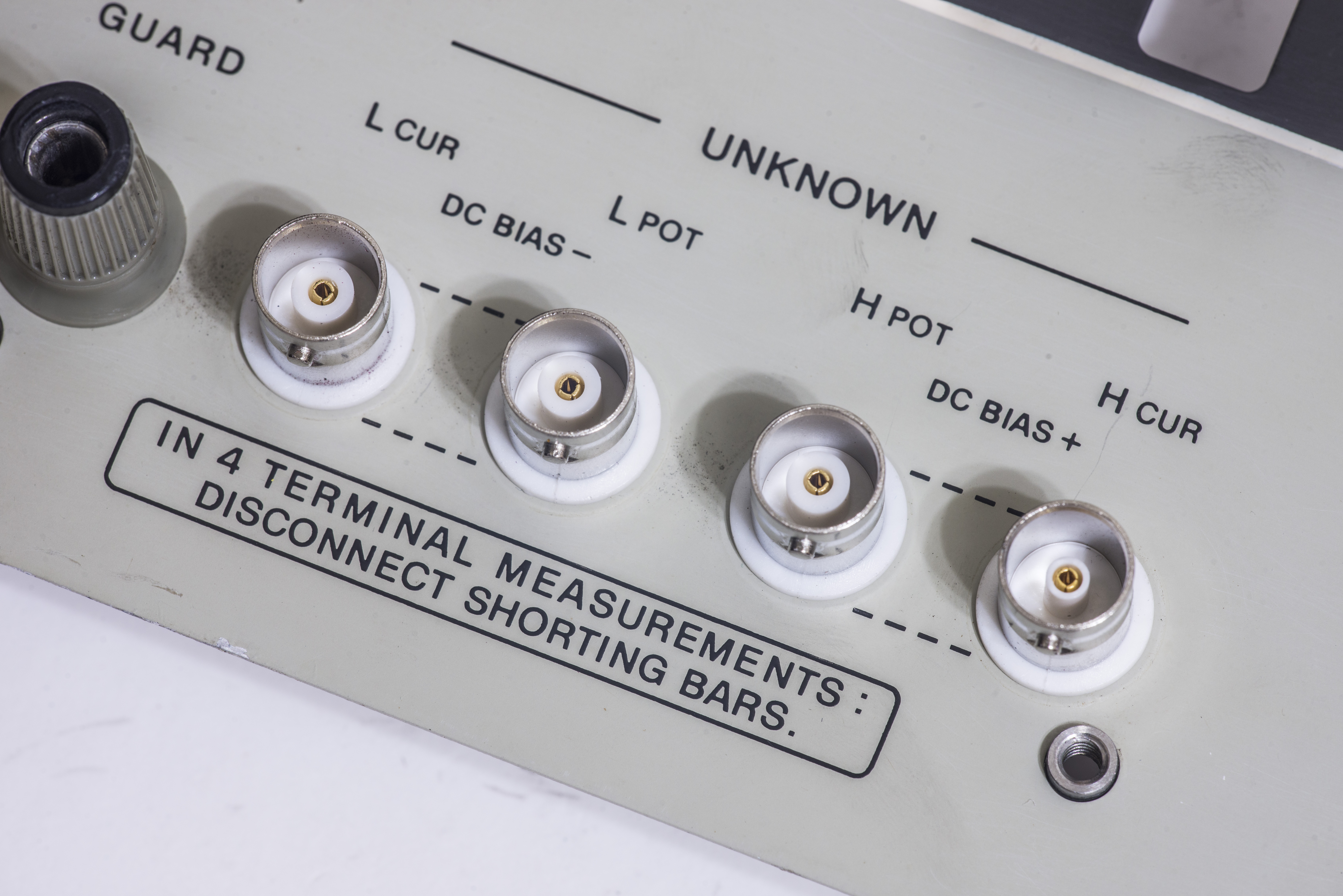
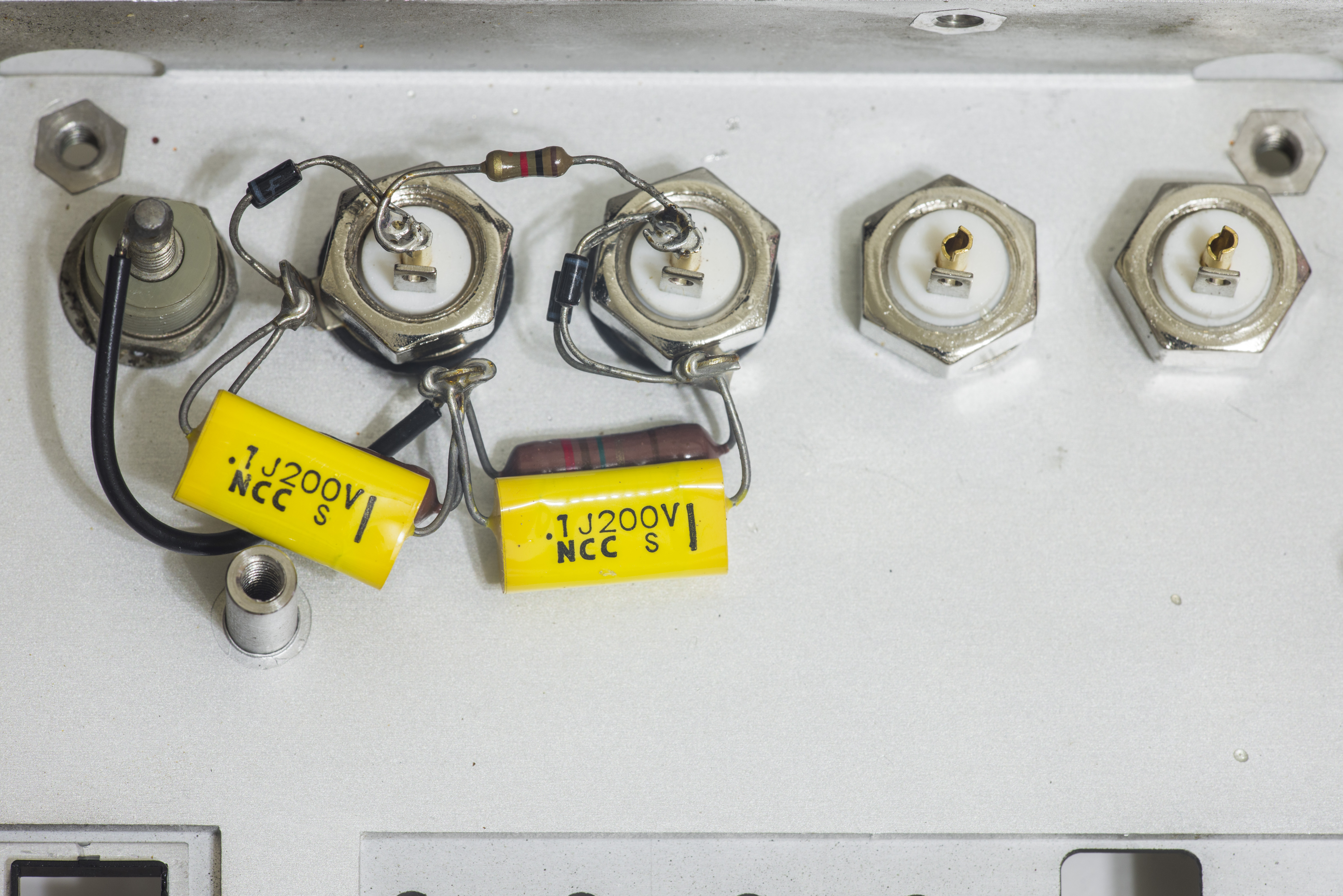
One of binding posts terminals have damaged housing and unable to fix securely on front panel frame. So it was decided to replace custom HP-specific binding post terminal and other three of them to new isolated BNC connectors. Most of modern LCR meters and fixtures are designed to use BNC-style connection, so with few limitations this will allow easier use of 4262A with other fixtures and test probes.
BNC connectors also mean that LCR will be required to do 4-terminal measurements, as it’s now there is no way for easy shorting bar between binding posts.
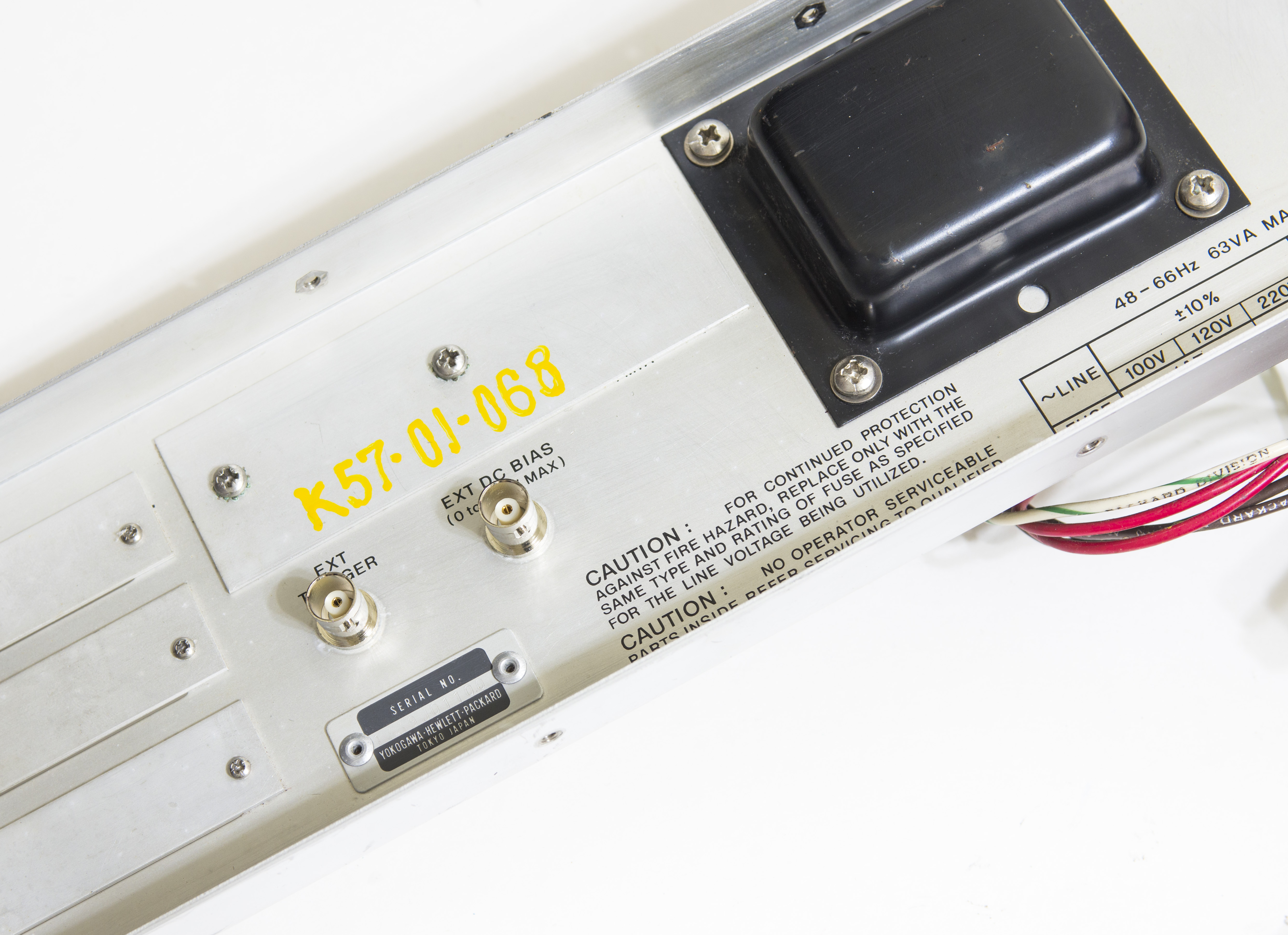
Rear rusty BNC ports for TRIGGER input and DC BIAS are also replaced to non-isolated cheap BNCs as well. Not worth to spend lot of time cleaning original connectors for cost of two generic BNC jacks.

TBD…
Now once cables are replaced, let’s try power it on and debug electronics issues. First of all, power supply repair.
It’s simple linear regulator, so after checking power transistors Q2 and Q3 (which were OK) only few parts remain to troubleshoot.
After electrolytic capacitors C1,C2,C3,C4,C5 replacement and U3 (used far too good Linear LT1007 here, since usually don’t have much stock for DIP8 opamps) negative -12V rail powered up like new.
Test result with fixed A9 power supply assembly:
| Test point | Expected voltage | Measured voltage | Result |
|---|---|---|---|
| +12V on A9 PCB | +11.95 … +12.05 VDC | +11.997 VDC | PASS |
| +5V on A9 PCB | +4.85 … +5.15 VDC | +4.998 VDC | PASS |
| -12V on A9 PCB | -11.85 … -12.15 VDC | -11.986 VDC | PASS |
| -5V on TP4 CPU board | -4.9 to -5.1 VDC | -5.021 VDC | PASS |
Meter front panel displays and indicators become functional and display meaningful information now.
To be continued.
Test and calibration
Operating manual lists some capacitance, inductance and resistance standards from GR to use with 4262A to perform performance test. As currently I don’t have any of those, general purpose parts, measured in same conditions with HP 4263B were used for checks. All three frequencies were used to measure test devices (100Hz, 1kHz, 10kHz).
| Used test device | Measurement by 4263B | Measurement by 4262A | Difference |
|---|---|---|---|
| 100pF capacitor | |||
| 1000pF capacitor | |||
| 10nF capacitor | |||
| 100nF capacitor | |||
| 1000nF capacitor | |||
| 1µF capacitor | |||
| 10µF capacitor | |||
| 100µF capacitor | |||
| 100 Ω resistor | |||
| 1 KΩ resistor | |||
| 10 KΩ resistor | |||
| 100 KΩ resistor | |||
| 1 MΩ resistor | |||
| 10 MΩ resistor |
Conclusion
It was fun little project, giving a good example of system design approach and modular construction for easy troubleshooting and service. Access to full service information is helpful to understand basic concepts of LCR measurements. It took around 20 hours to repair and test this HP 4262A unit.
Bench LCR-meters are usually not an everyday tool for most of engineers, unlike oscilloscope or DMM, but when you need it, there is no replacement. HP 4262A is still better choice than most of cheap portable meters, especially if you can get one in working condition for under 200$ USD. It does take fair bit of space though with it’s not regular size. Also base version does not have communication interface, so using it in automated environment need addition HP-IB option card.
Modified: Aug. 22, 2018, 4:16 a.m.