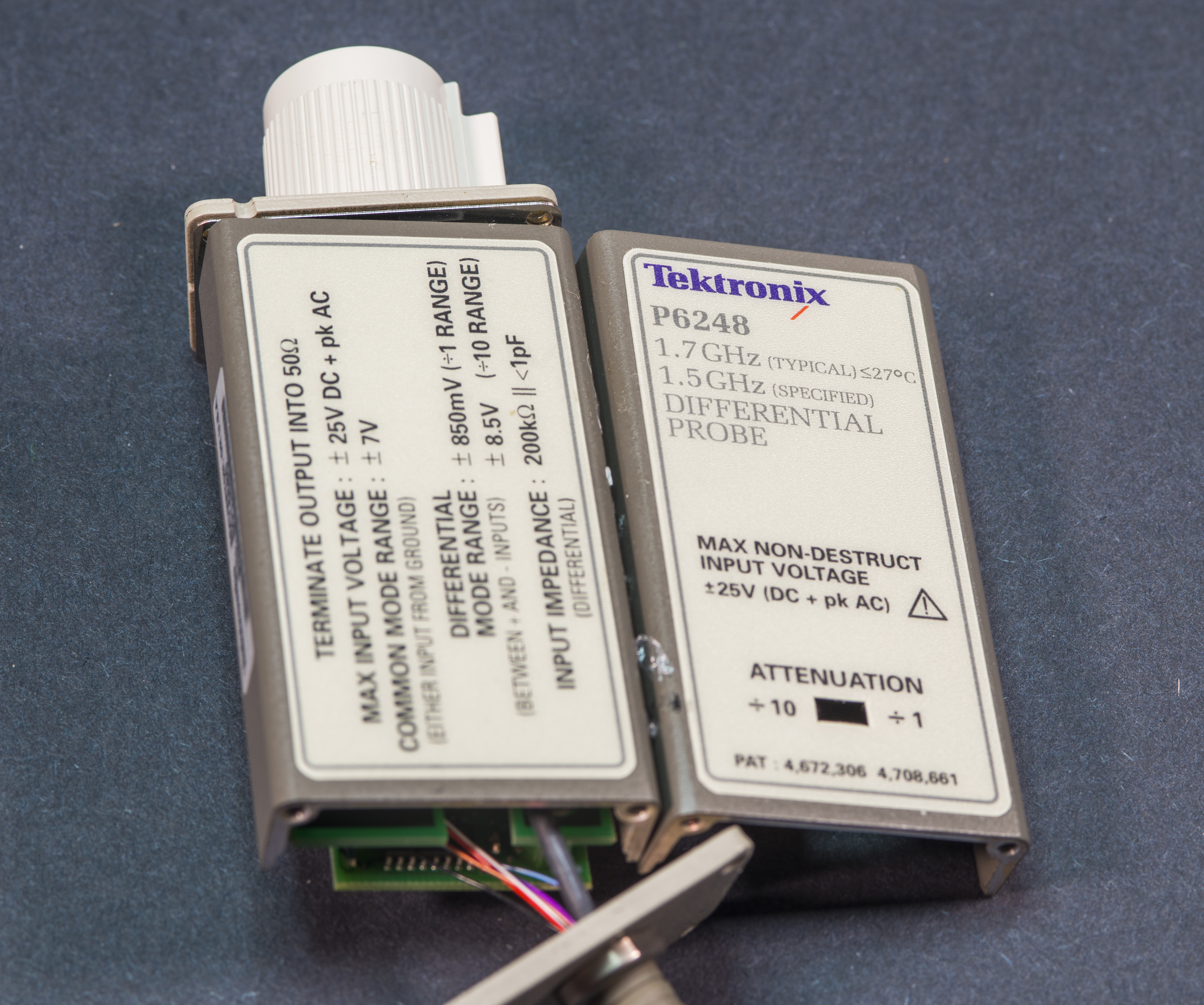
This Tektronix P6248 is rated for at least 1.5 GHz of analog bandwidth and designed to operate in single-ended or differential mode. It is highest bandwidth model in P6246/P6247/P6248 series.
I’ve been using and photographed P6246 probe before. It was essential probe to troubleshoot USB 2.0, fast SPI, bus strobes and clock/PLL circuitry on digital designs, such as Intel motherboards and NVIDIA graphic cards.
It have good high-speed electrical and robust mechanical connection head for working with high-speed digital designs. This is older generation probe designed for Tektronix oscilloscopes with older TekProbe™ BNC ports (but also can be used on newer scopes with TekVPI with TPA-BNC adapter).
Feature set of this probe:
- 1.5 GHz analog bandwidth guaranteed (1.7 GHz typical), rise time <265 ps
- Less than 1 pF differential input capacitance
- 200 kΩ differential input resistance (100kΩ single-ended)
- ±7 V (DC+pk AC) differential input voltage and input offset range
- Attenuation x1 or x10
- Noise level less then 50 nV/squareroot Hz
- >25 dB CMRR at 1.5 GHz or >60 dB at 1 MHz (x1 mode)
I’ve bought this probe as broken/for parts. MSRP for the new Tek P6248 is around $7960 USD.
Diagnostics
Probe had no physical damage from outside, did not have any accessory bundled with sale. After connecting to Tektronix DPO7104C scope probe was correctly recognized and identified.
AC square-wave from scope’s calibration output did not show up on the scope. Feeding signal either to negative or positive inputs of the probe did not show any signal on the scope, even with most sensitive 2 mV/division range. There was no excessive heating on the head.
Teardown and repair
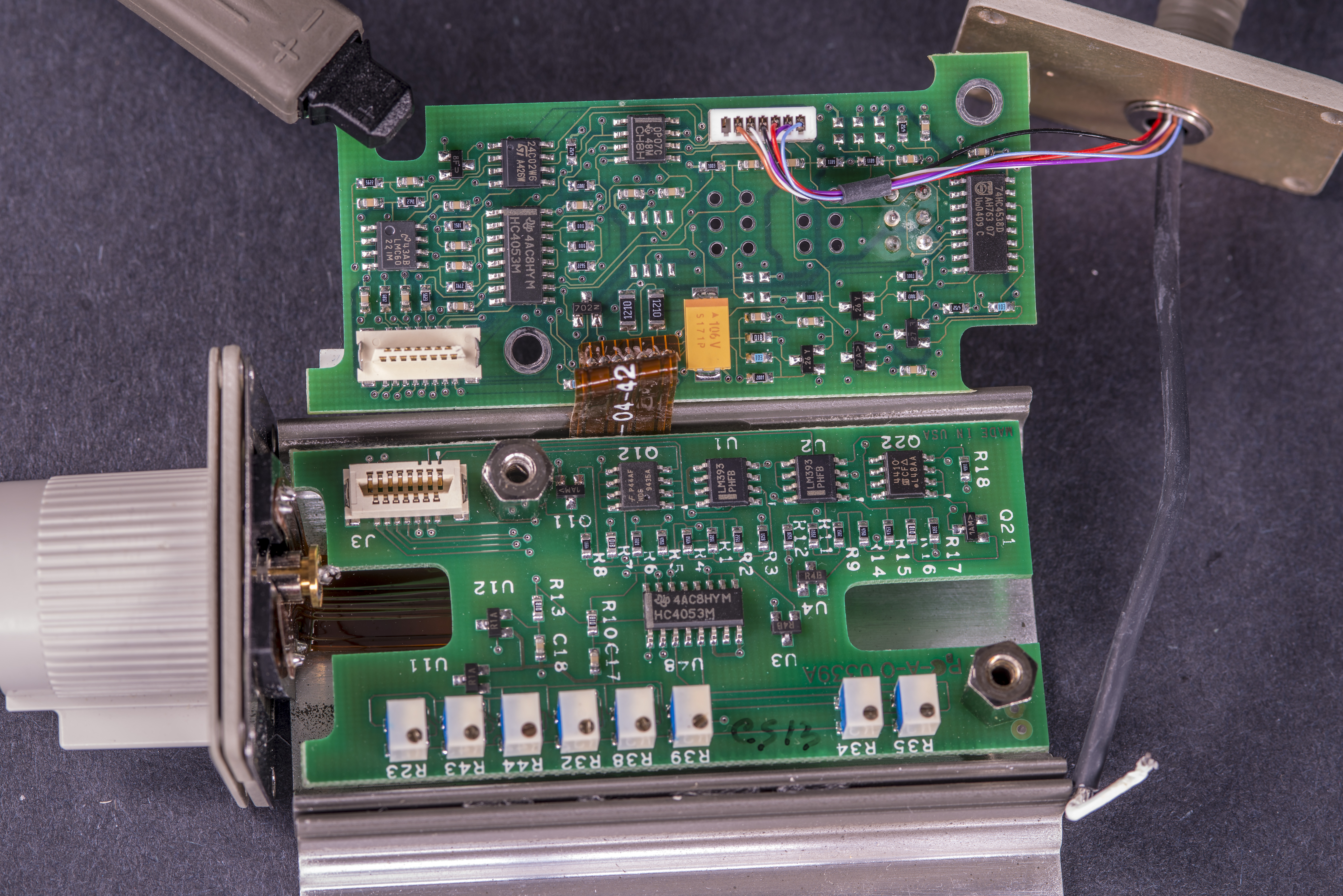
Probe has all auxilary electronics in connector head, that plugs into TekProbe Type II oscilloscope port. There are two PCBAs, mounted to each other with help of board to board connector.
Typical to Tektronix probes, there is some active circuitry, including two ATMEL 24C02 I2C EEPROMs to provide digital probe identification for scope, store serial number, calibration, etc.
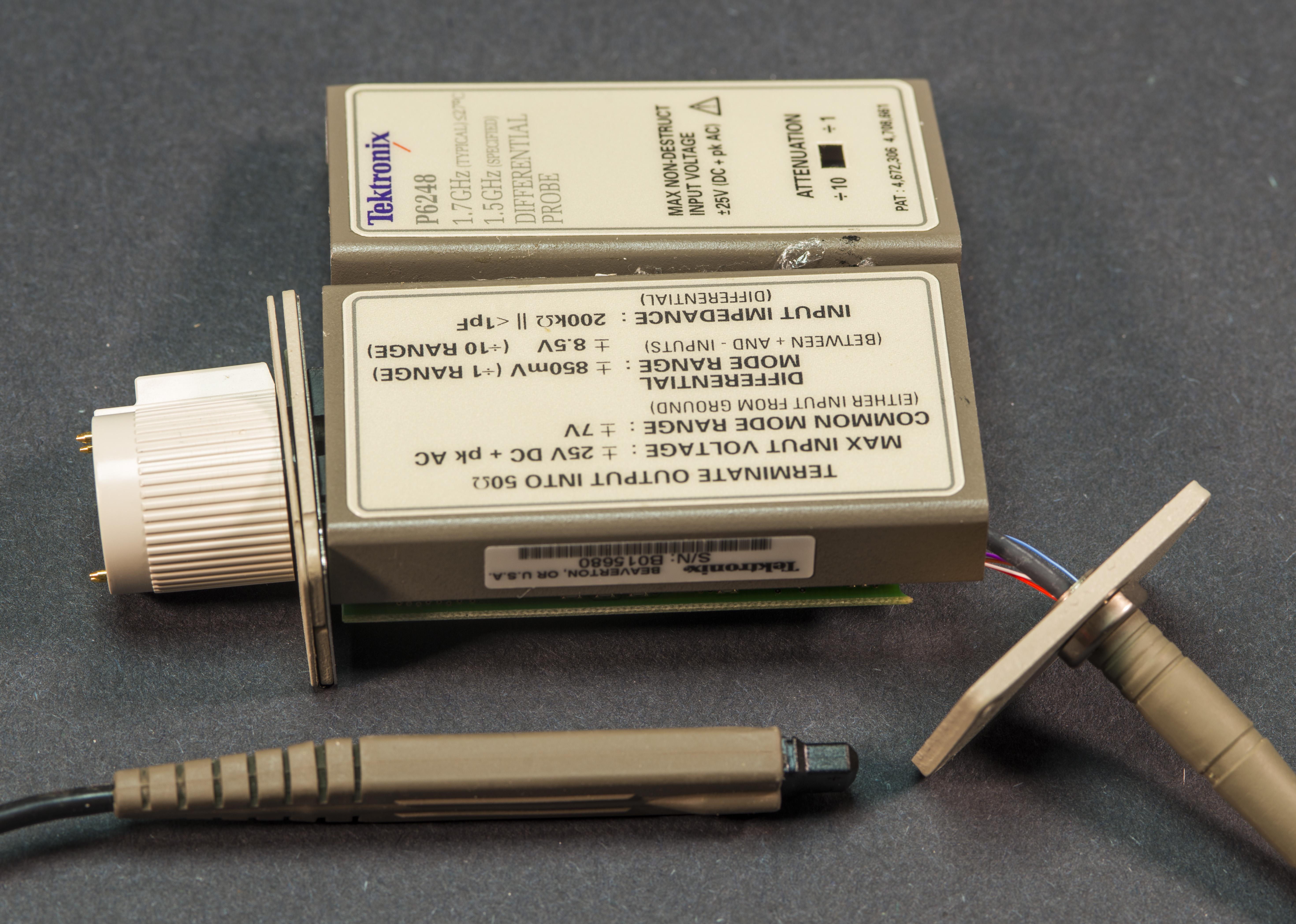
This is low voltage probe and designed for ±850 mV or ±8.5 V range signals, terminating into 200 kΩ impedance.
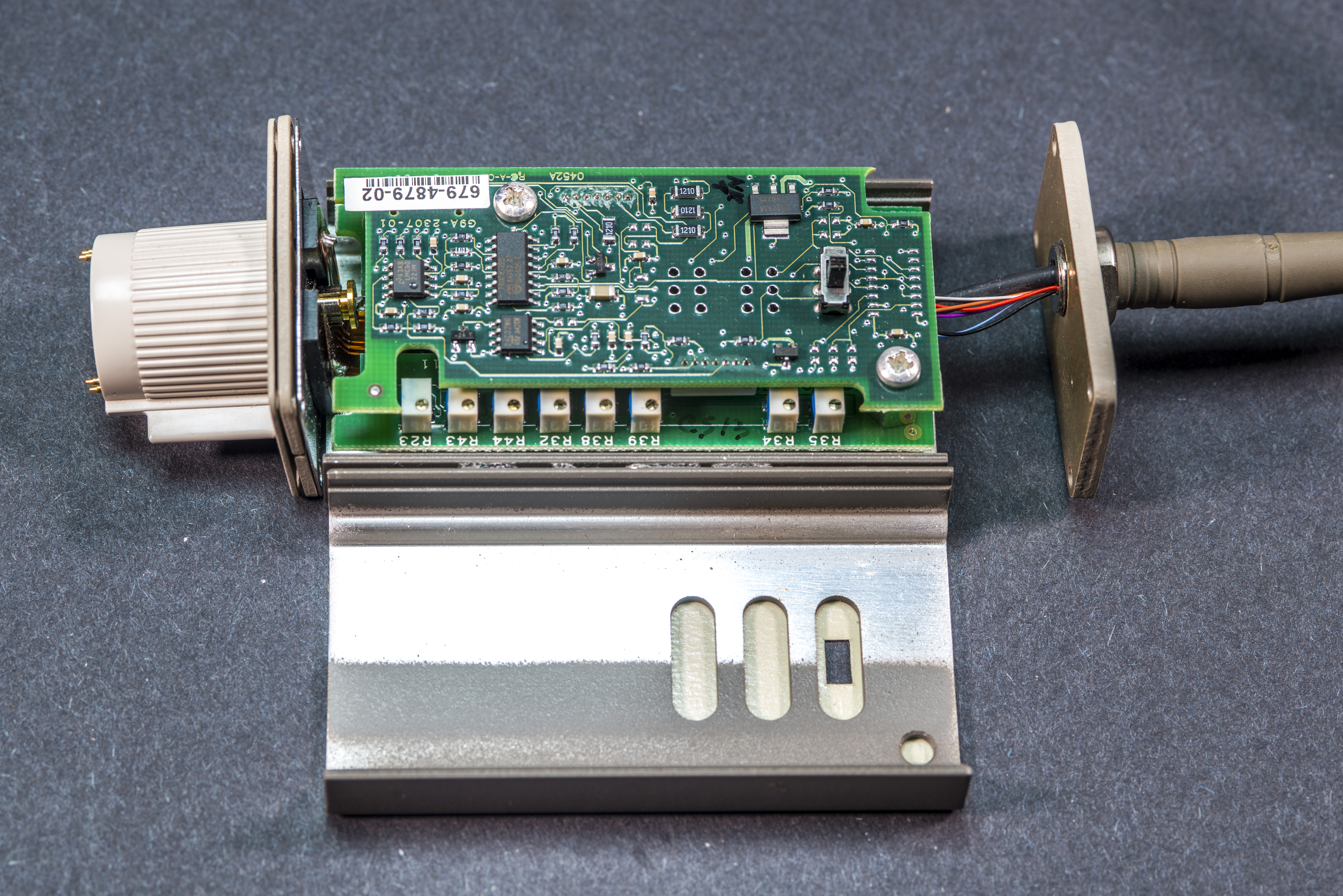
Bottom PCB has whole row of eight tiny potentiometers for calibration and adjustment purposes.
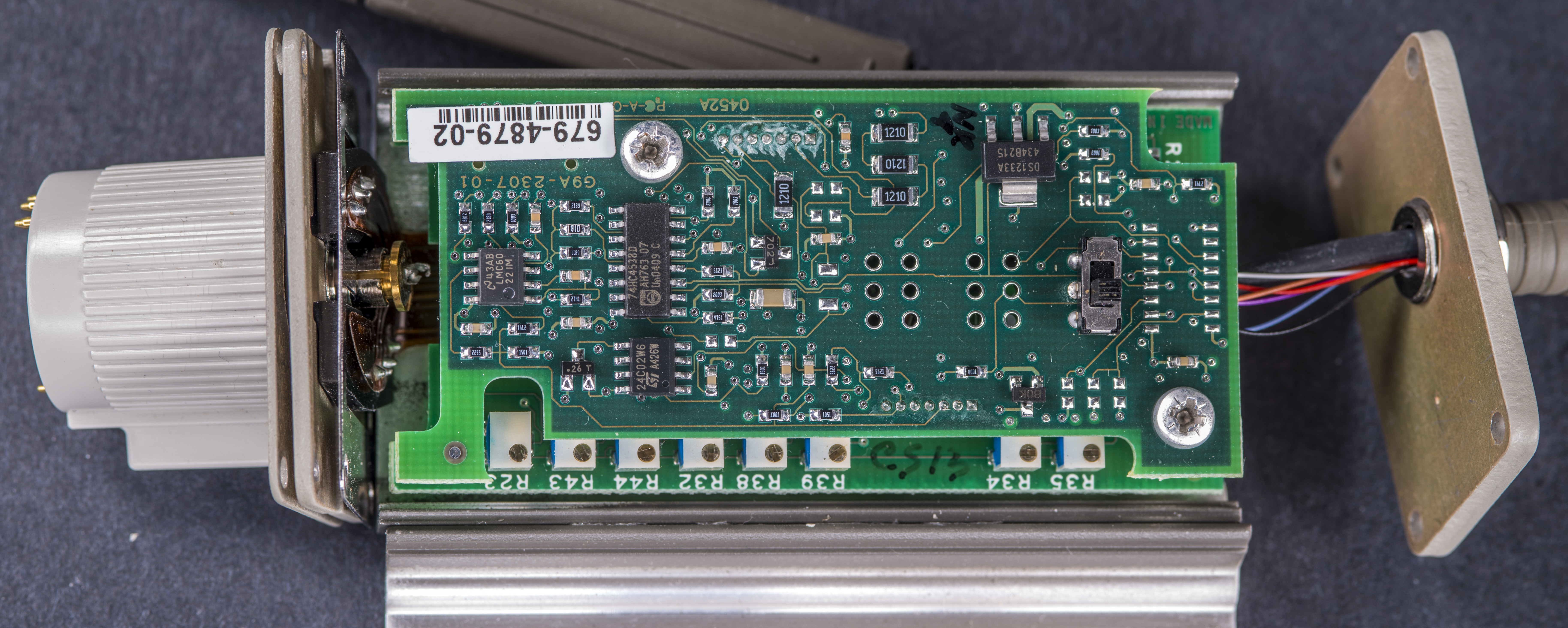
There are also few ultra-low bias current high gain TI LMC6022 and OP07C amplifiers, Intersil HP4410DY 30V N-channel MOSFET, some LM393 comparators, ubiquitous HC4053M multiplexes and few more logic chips.
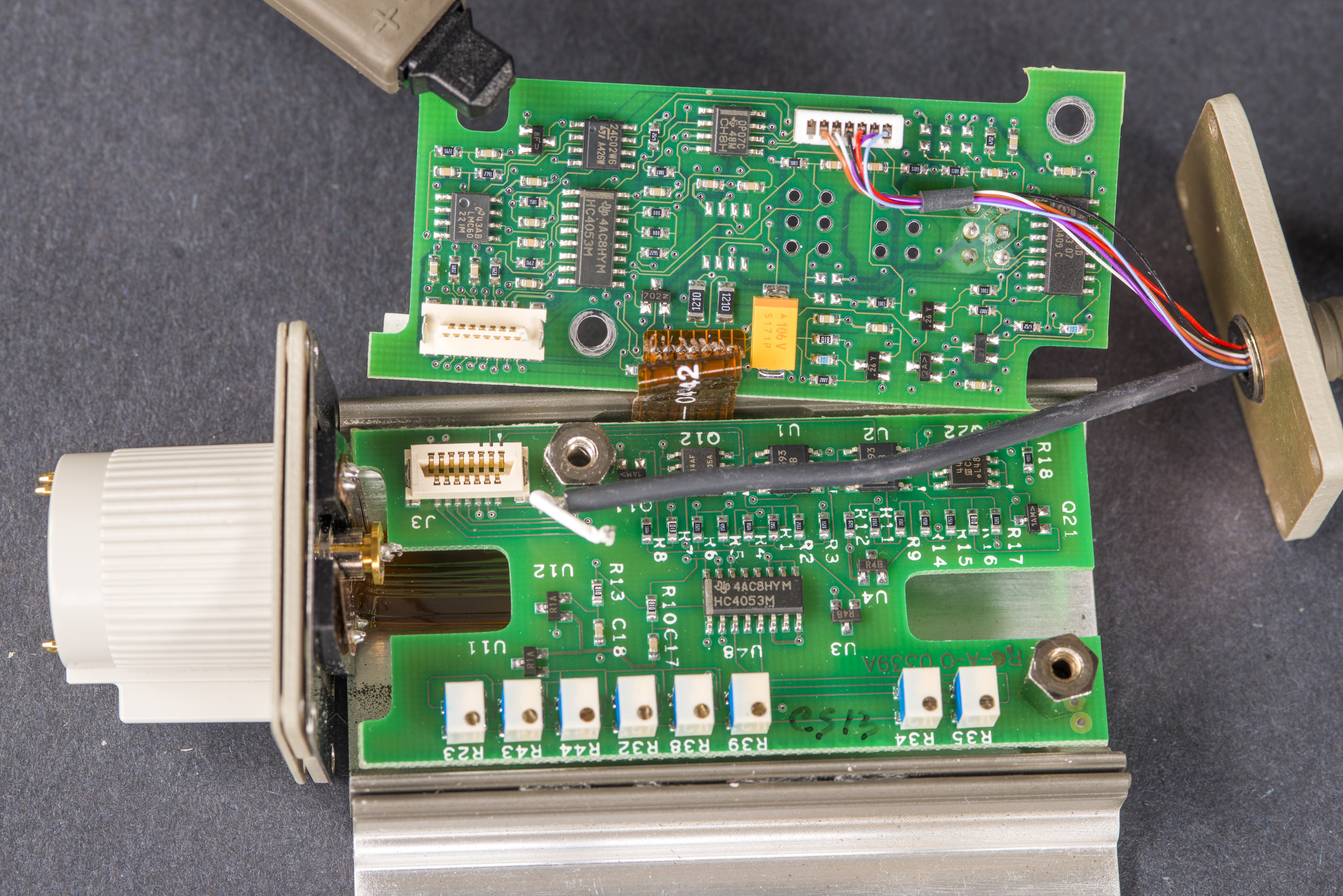
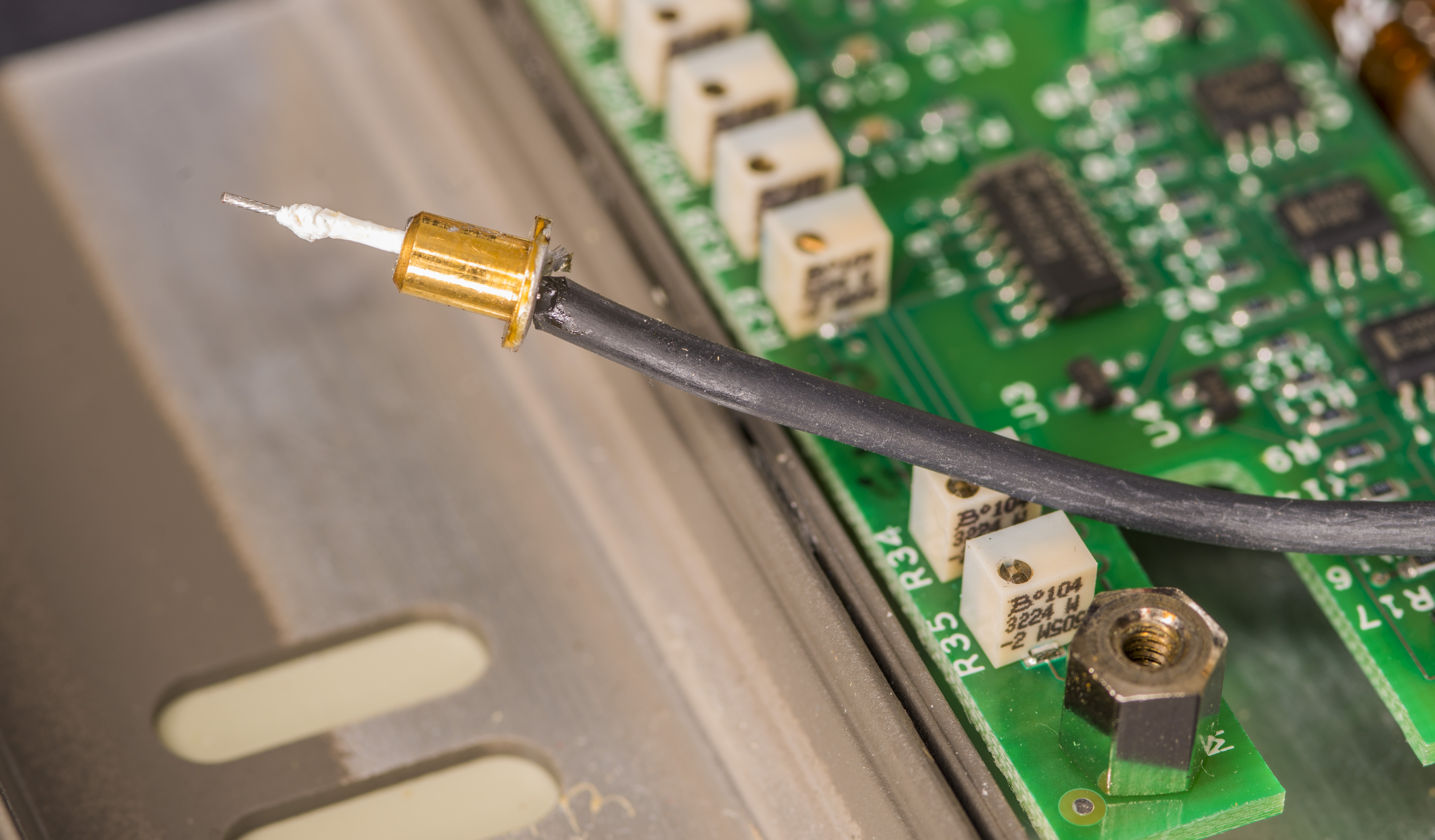
Now issue why no signal was present on scope should be clear. RF coaxial cable from active head to BNC connector port is mechanically torn apart!
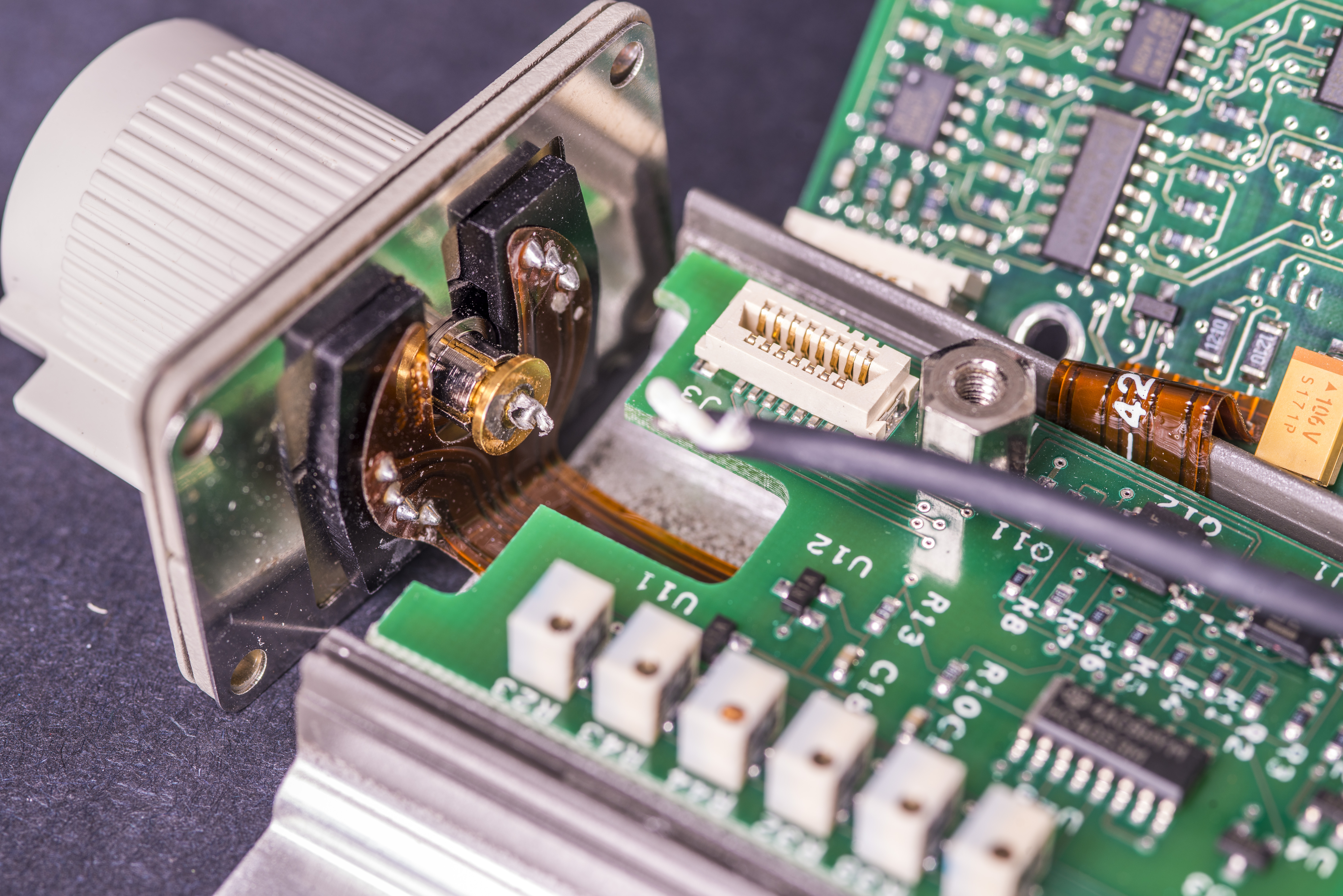
Golden insert that normally soldered to shield in coaxial still have few pieces left on it.
Insert termination was resoldered back to the RF cable after careful cleaning and exposing little more of shielding braid in cable. Lucky for us cable was little longer than required, so no other modifications or operations required to restore connection. Center wire is plugged directly into BNC port receptacle to connect with inner contact.
Now we can put probe back into enclosure and check what DPO7104C will say about it.
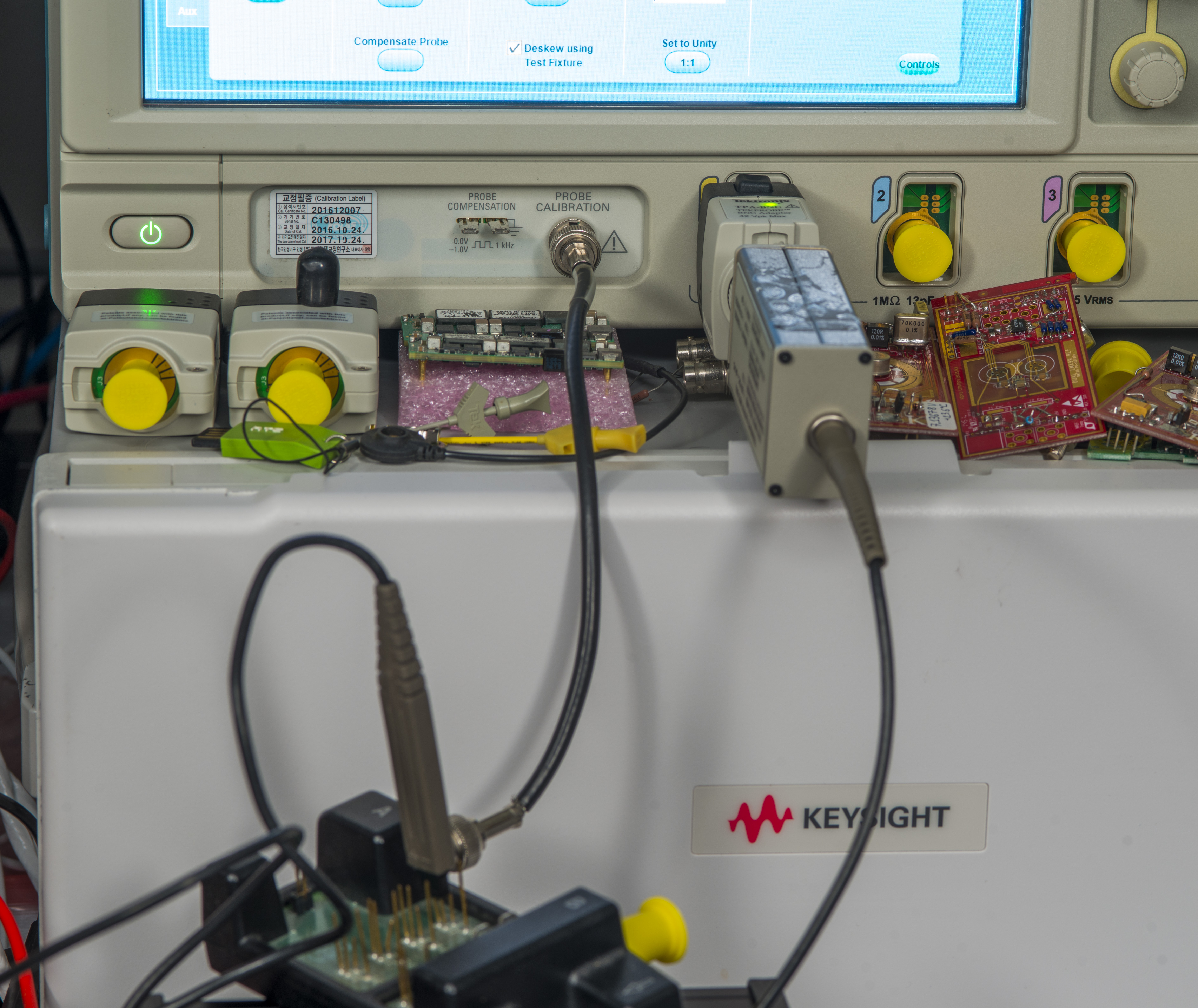
Benchmarks with DPO7104C
Probe was detected correctly and now connected signal from scope calibrator output indeed show up on screen.

With probe switched in x1 mode probe DPO7104C (1 GHz scope) able to demonstrate about 500 ps rise time. Quite a bit of ringing also present which could be due deskew fixture use rather than proper high-speed RF connection at the probe tip.
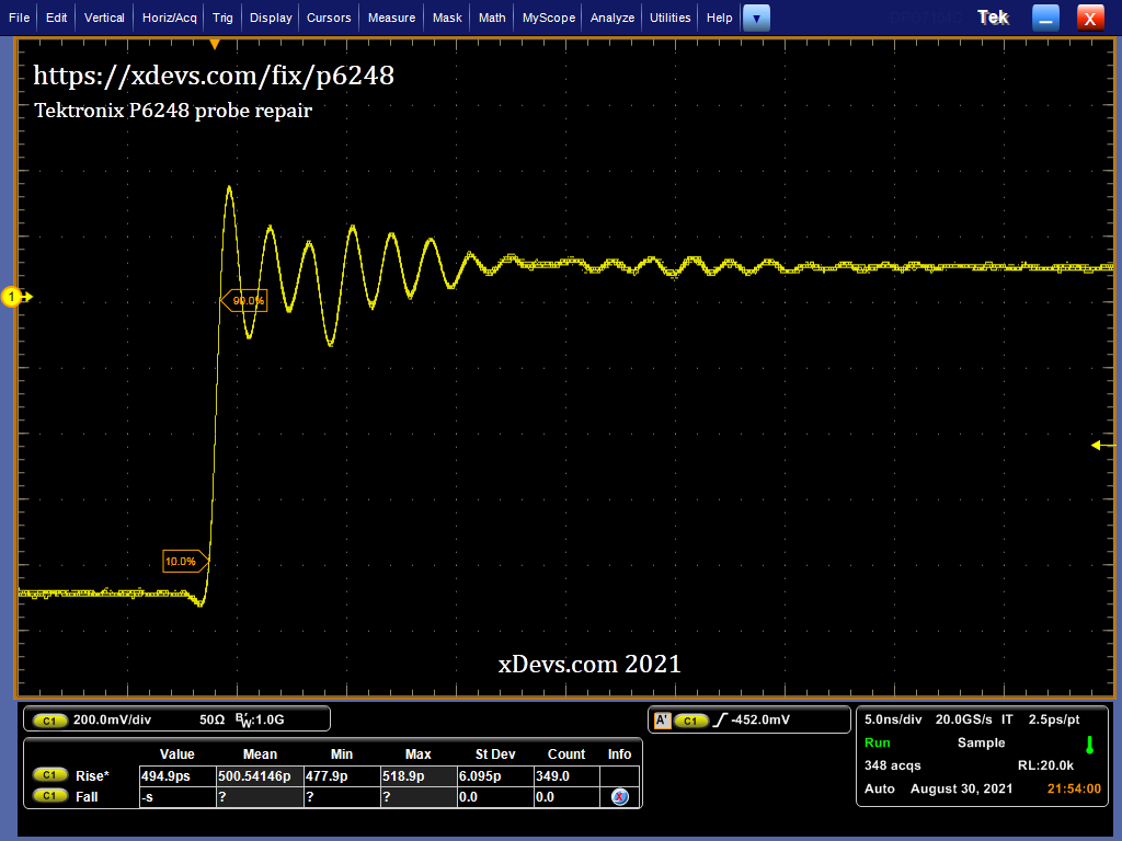
Fall time in same configuration is significantly slower at 4.04 ns. No wonder Tektronix does not specify fall time in their promo page ;).

Probe also passed deskew and compensation calibration from scope interface.

Repeated test in x10 mode for rise time measurement shows bit different result, with rise at 582 ps and fall at 2.512 ns.

Conclusion
This was rather easy and quick repair of expensive differential probe. There was no electrical damage, only mechanical issues which is often best case scenario for test equipment repairs.
Modified: Aug. 31, 2021, 1:10 p.m.