Contents
As some may know already, as a New Year 2016 gift I jumped into precision time-related repair project.
What else it is, if one who don’t even have frequency counter (yet?) buys no less than five broken rubidium standards, for this repair project

Units in topic are TEMEX / SpectraTime LPRO, which are basically LPFRS with heatsink and little coupling PCB. Quick googling revealed next useful links:
http://www.spectratime.com/products/isource/
http://www.egidy.de/temex_lpfrs_lpro/
http://www.eevblog.com/forum/projects/building-a-rubidium-freqency-standard-at-home/
http://time-nuts.febo.narkive.com/ssfEAnts/temex-lpfrs-01-analog-frequency-adjustement
Here’s what I received today (lightning fast DHL shipment, yesterday I paid for them, today 3pm I got them delivered!).
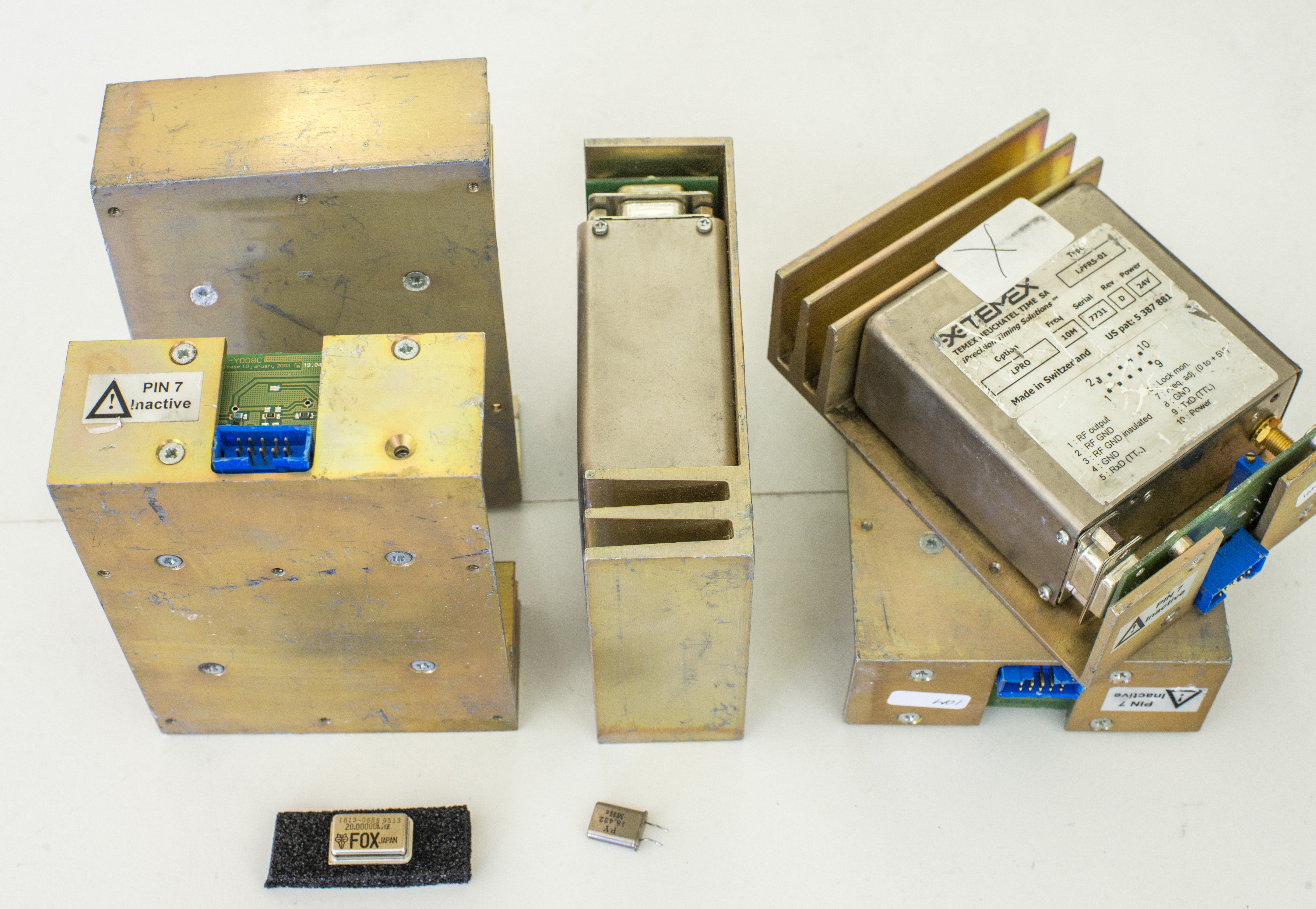
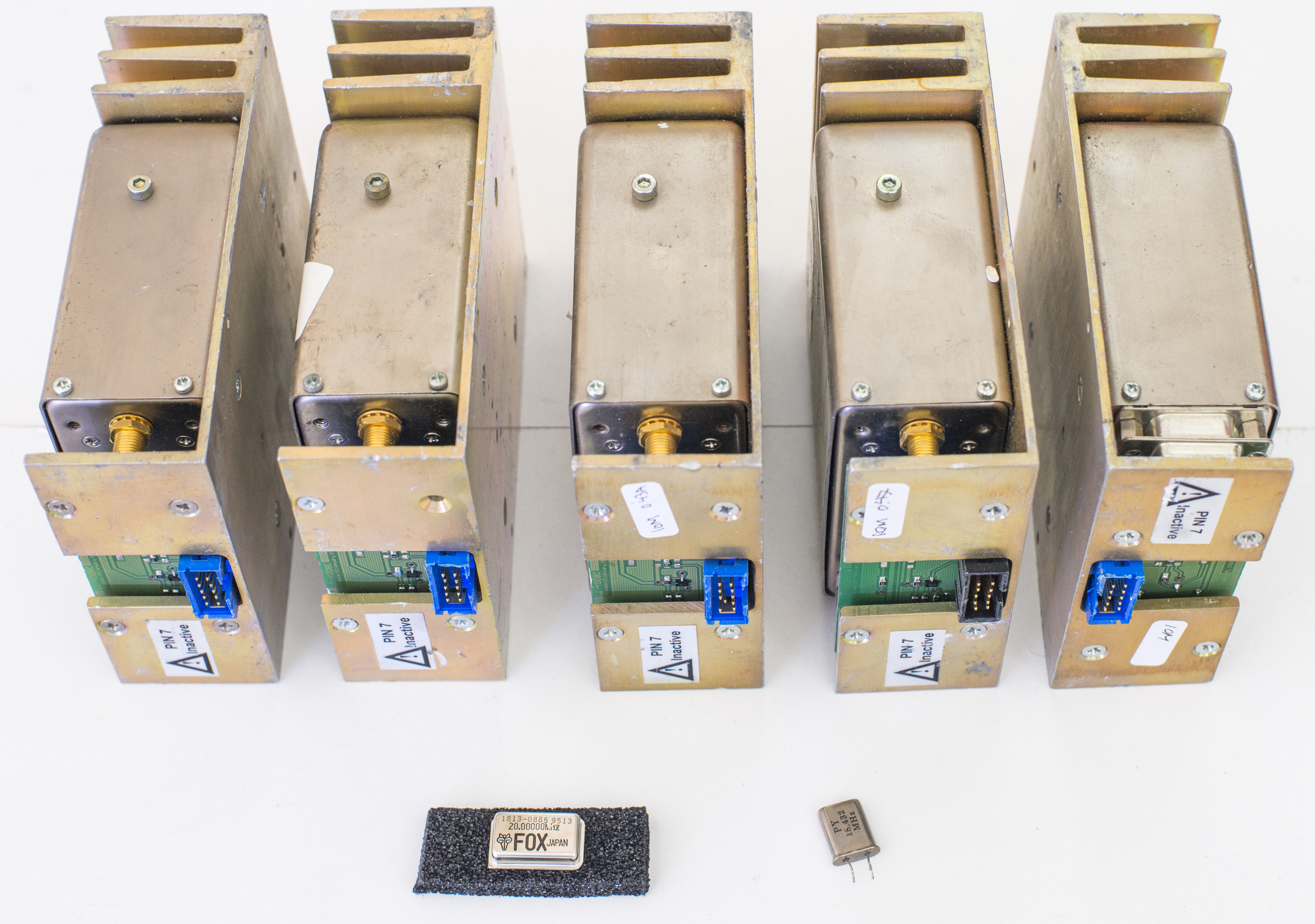
Rather bulky and heavy things, 500gramms each. I still confused about purpose of those heatsink fins and frame, as whole thing is ovenized, so why to add extra mass?
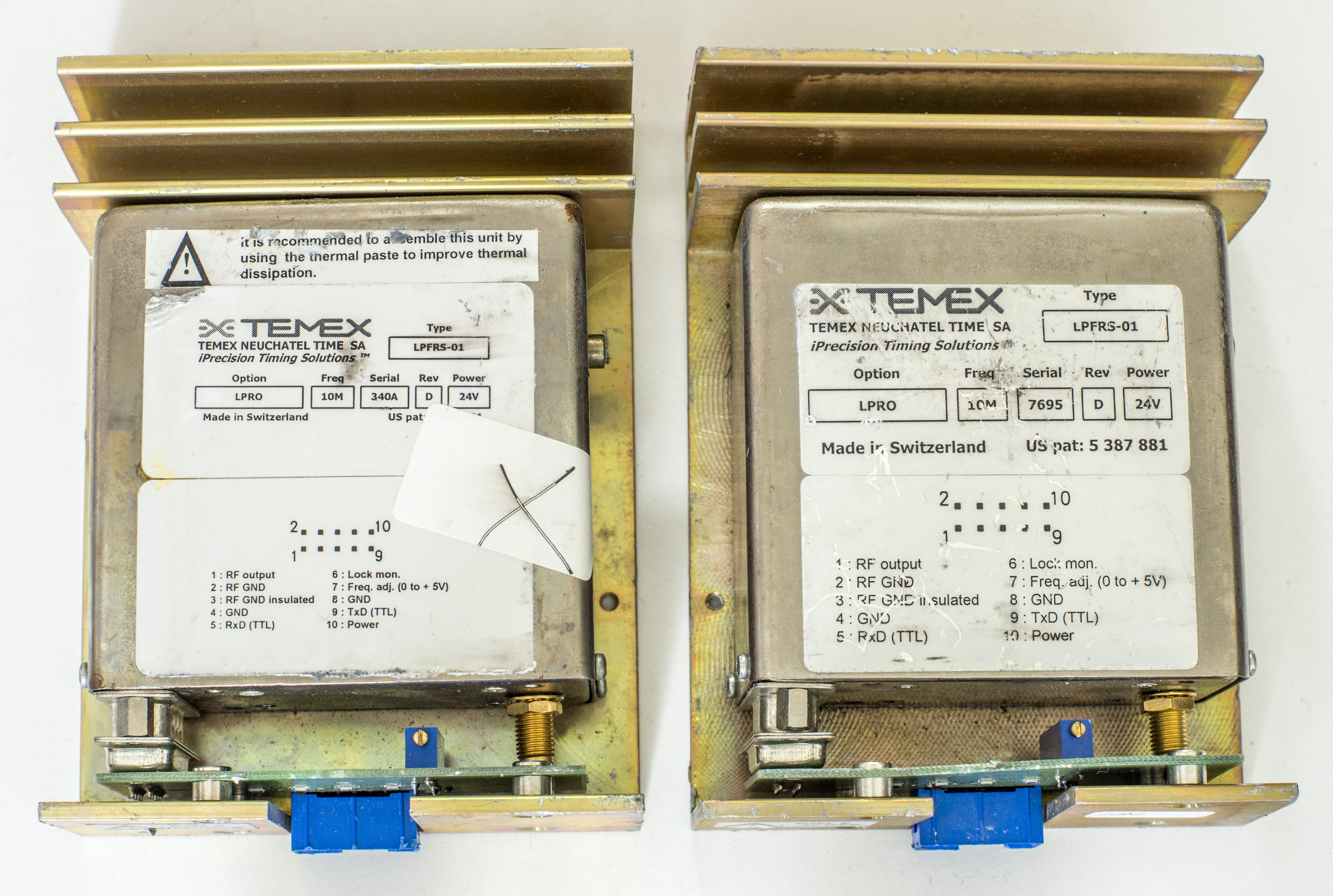
All five are same units, with minor changes in labels, specced to power at +24VDC, have 10MHz output and RS232 TTL interface, as well as adjustment and lock pins.
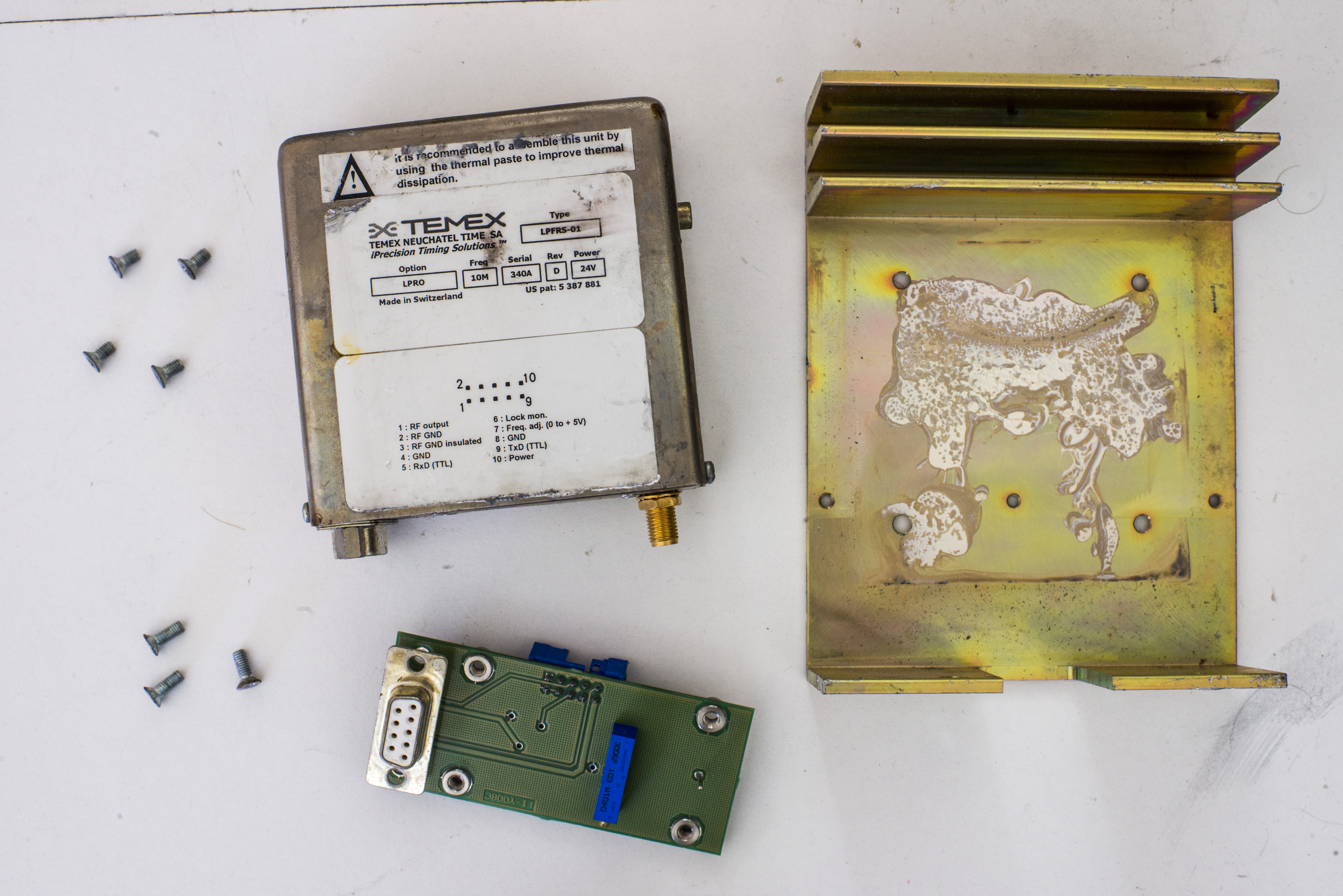
Removing some screws allow to easily take mu-shield off:
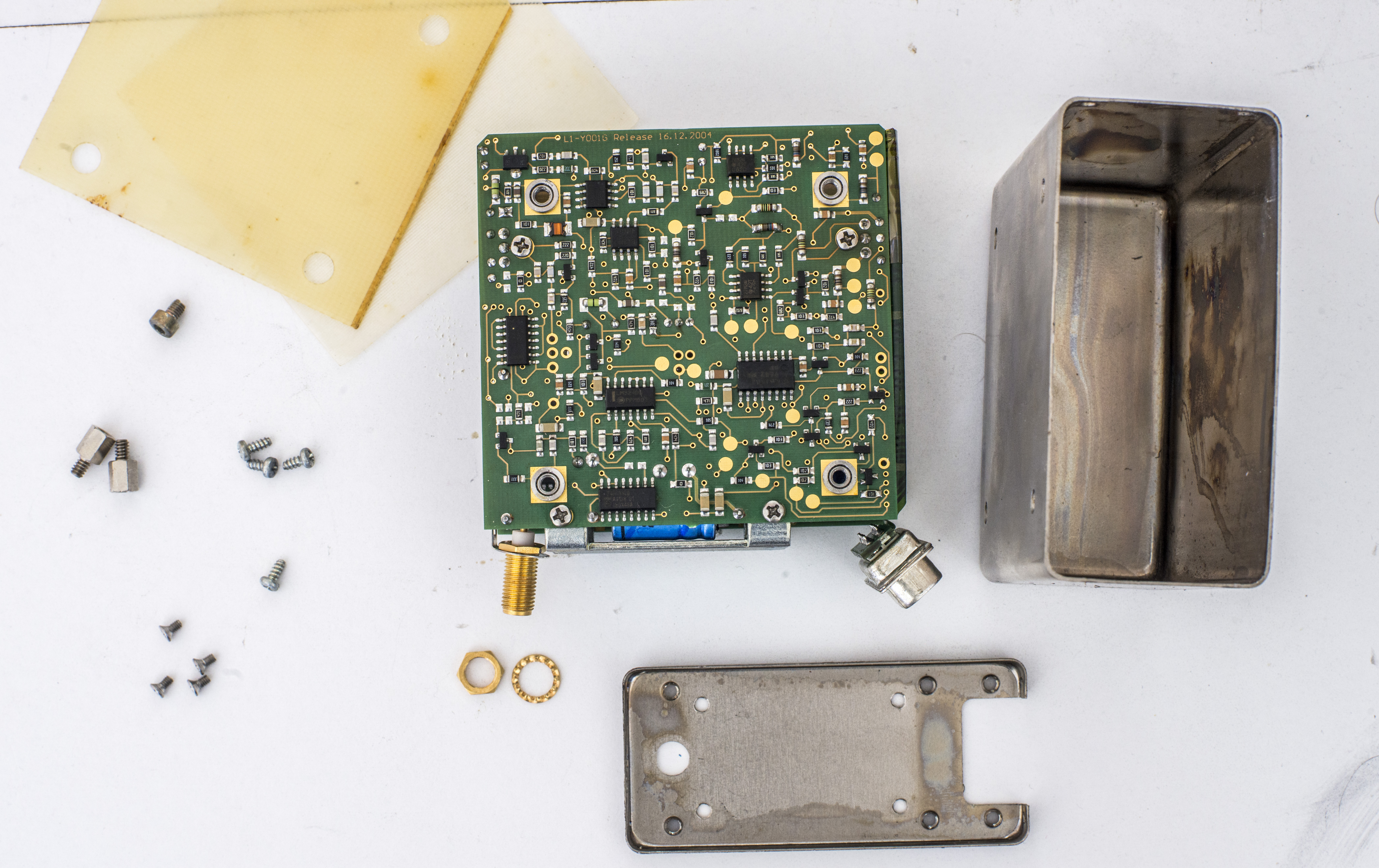
Two rather dense populated PCBs interconnected by in-core flexible layer and mechanically locked together via Rb chamber outer case.
Chamber is heater from both sides with TO-220 FETs.
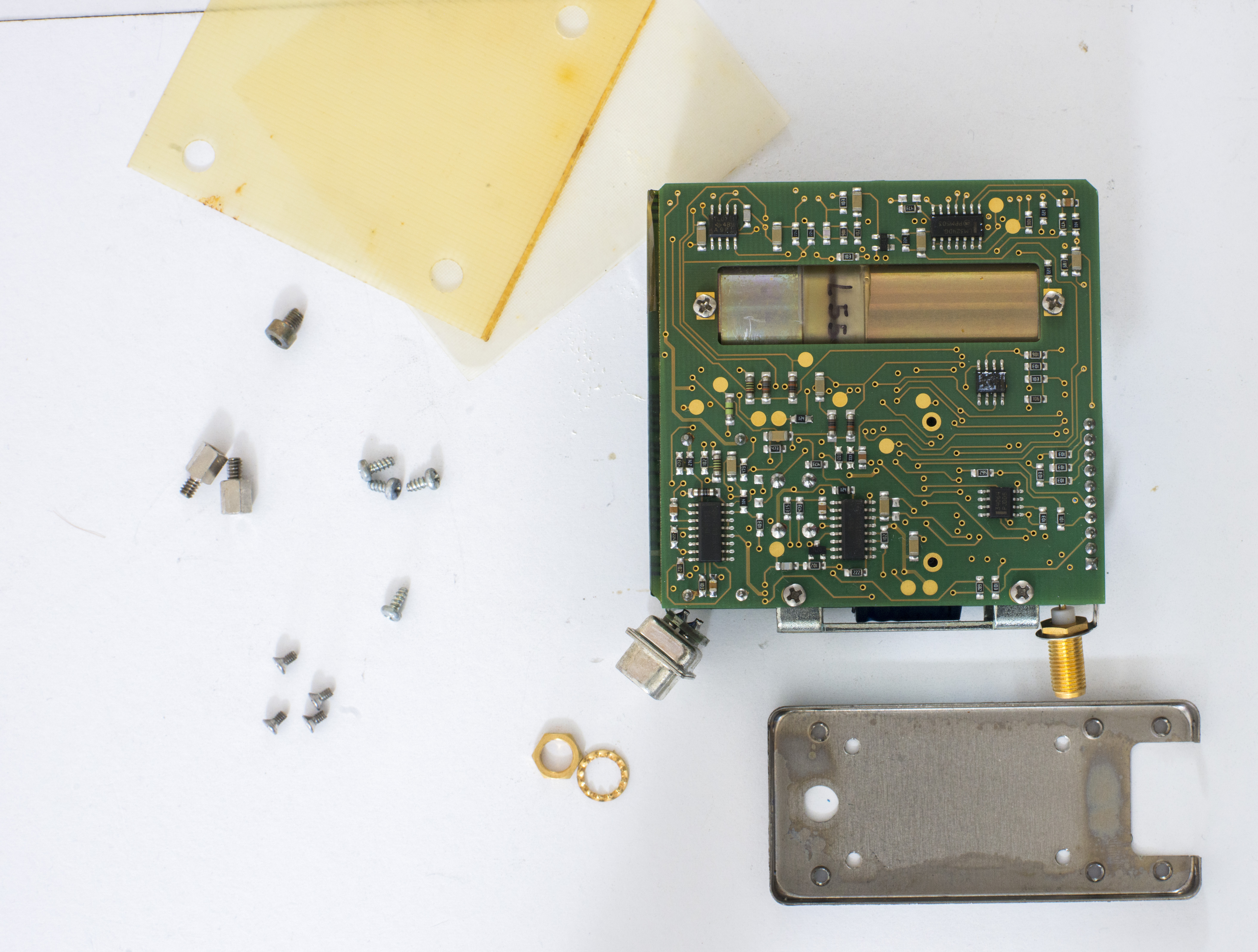
Here’s look on PCB from outer sides:
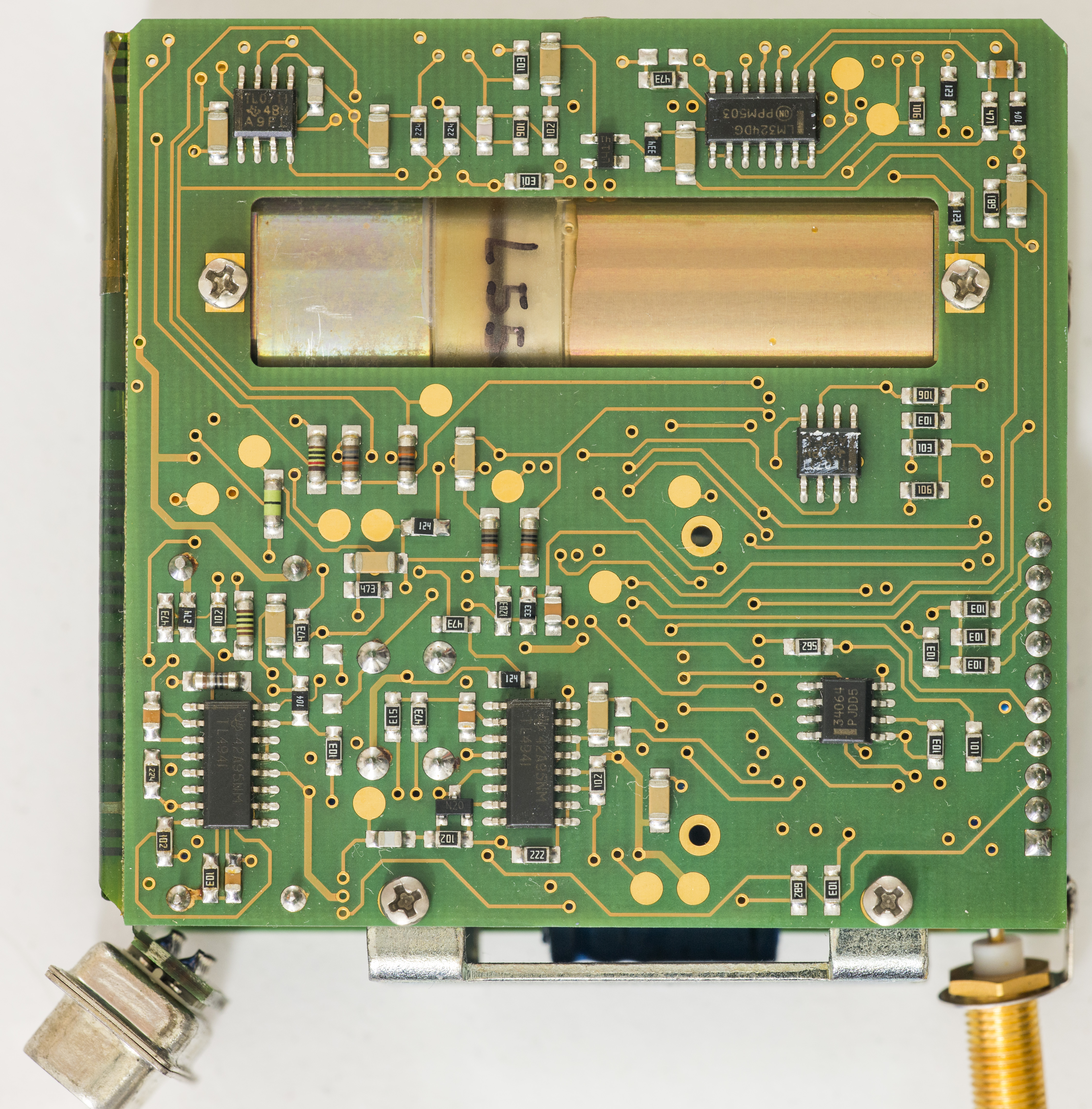
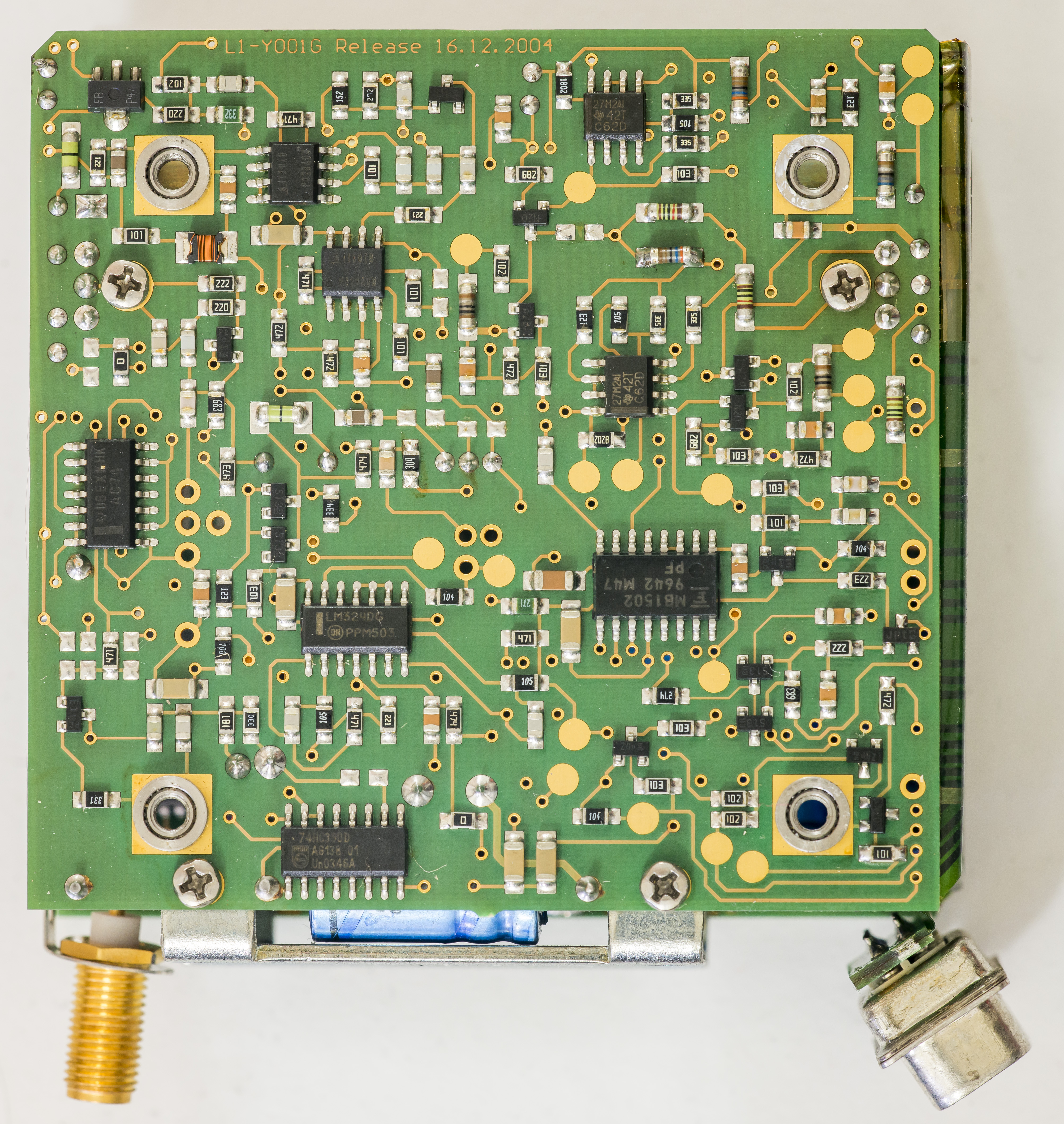
And inner sides:

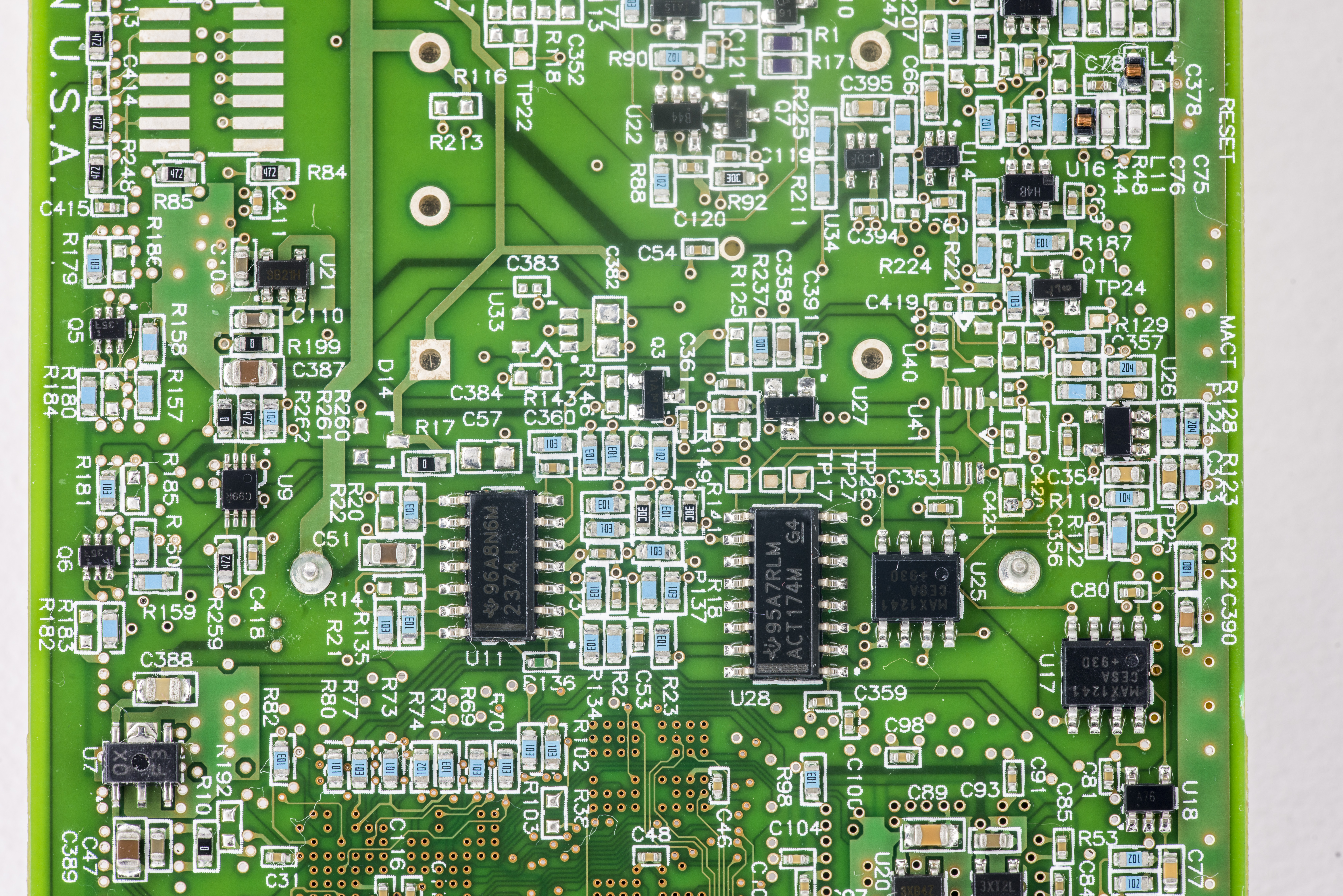
Motorola HC11 series MCU, DAC8800 and bunch of logic chips around.

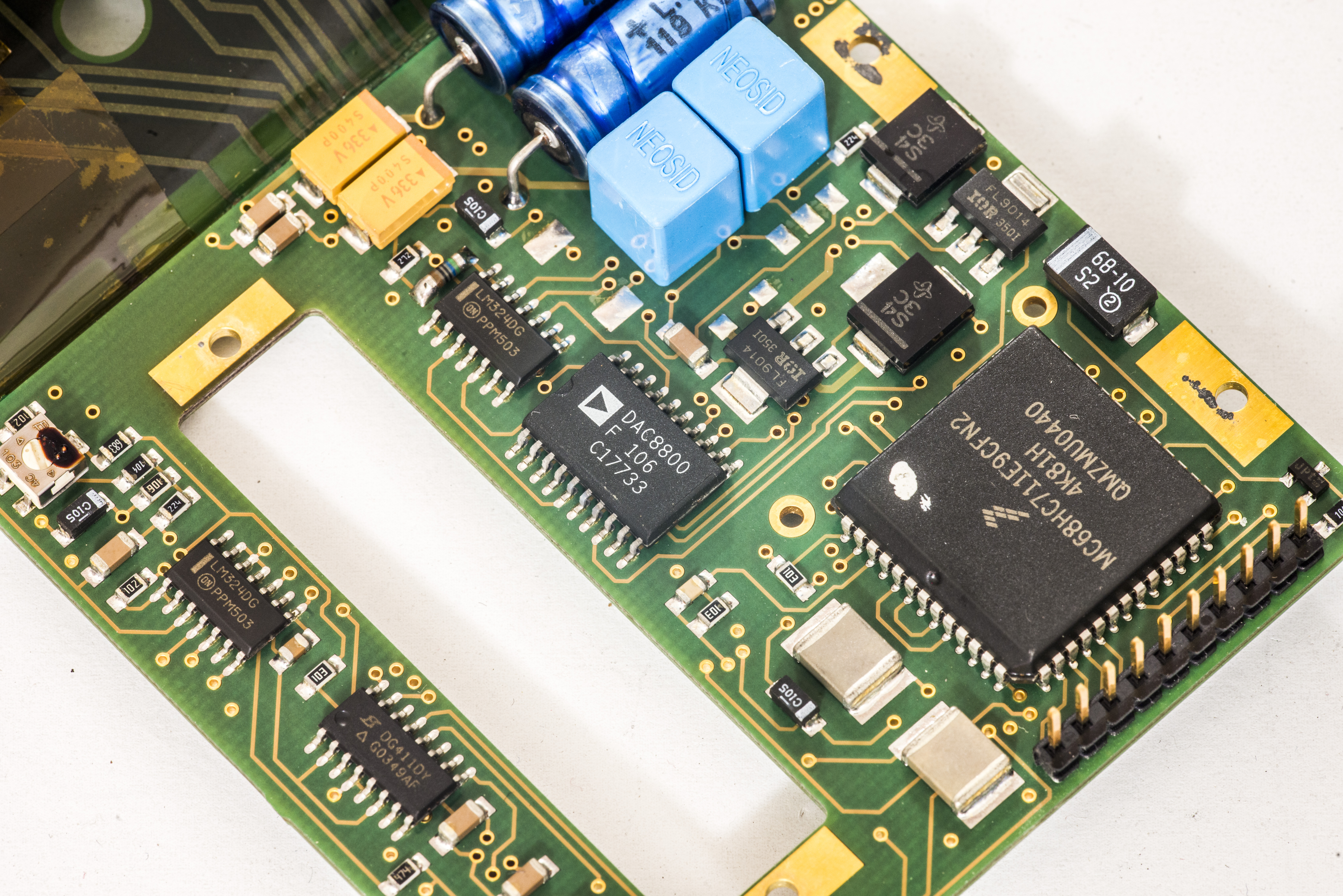
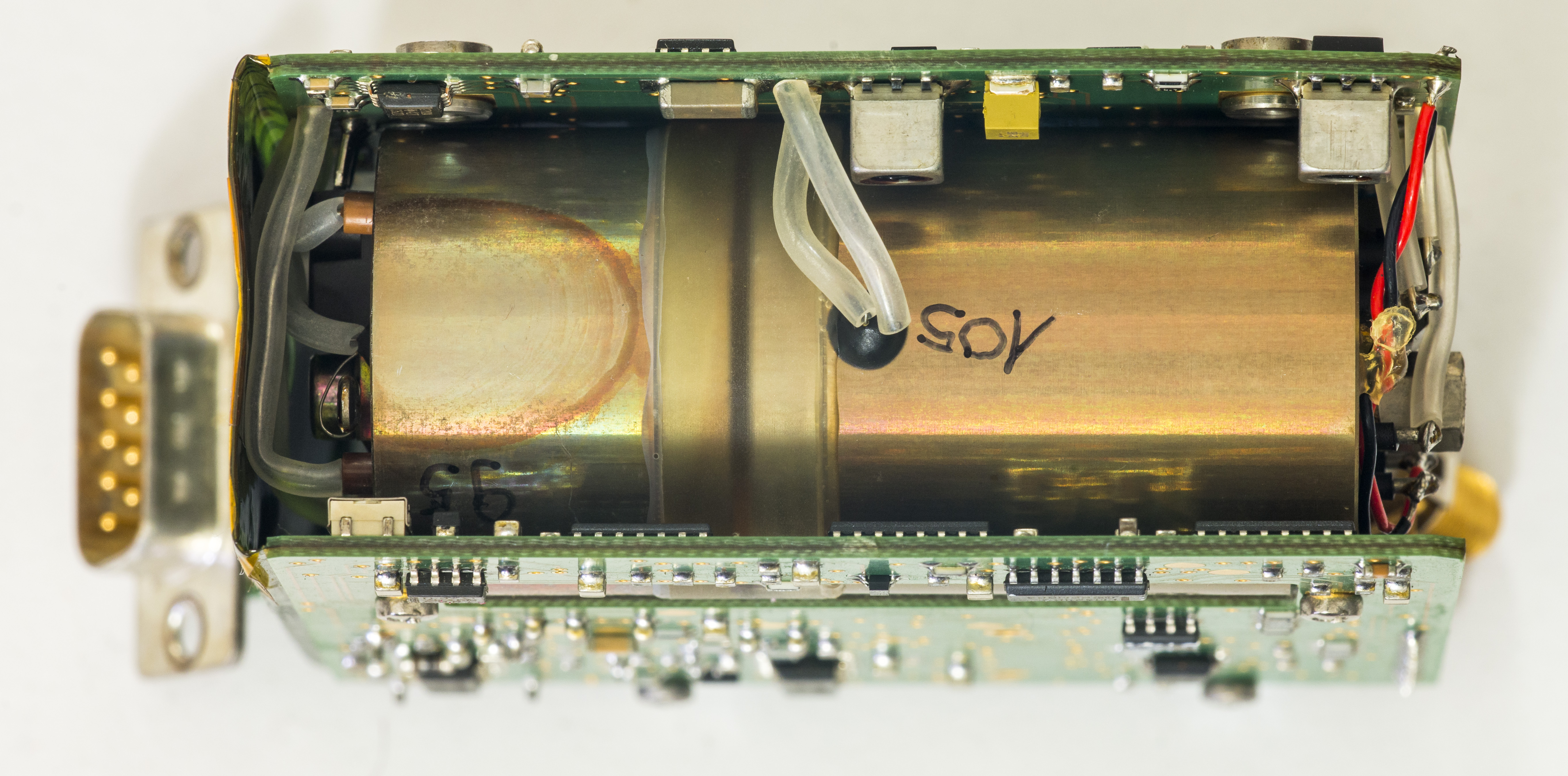
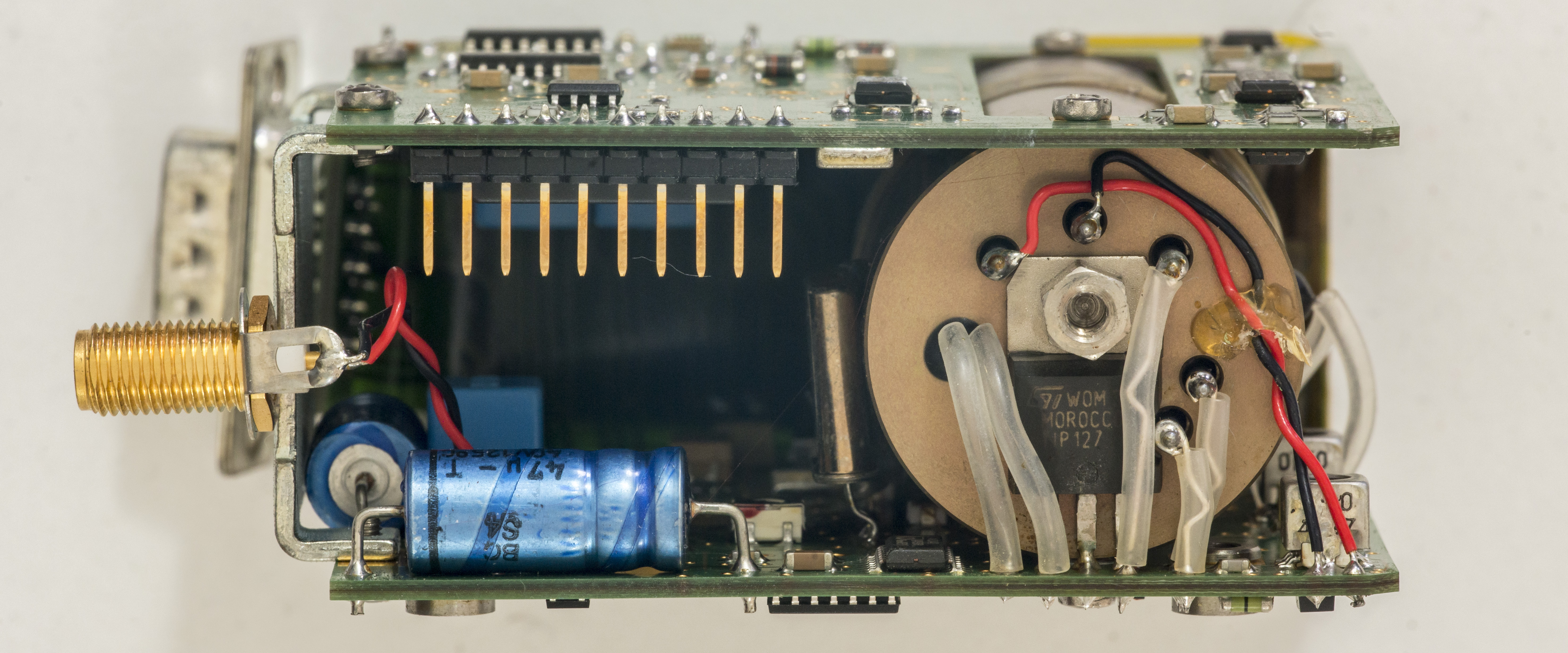
Closeups..

There are two XO’s glued to side of Rb chamber, 20.000MHz (bigger can) and 90MHz (smaller can in center). Some SMT trimpots and adjustable inductor(?) are nearby as well. Smaller part of chamber is lamp, bigger one is Rb cell with photodetector.
How do I know? Well, I turned this one in to see magic atomic glow…
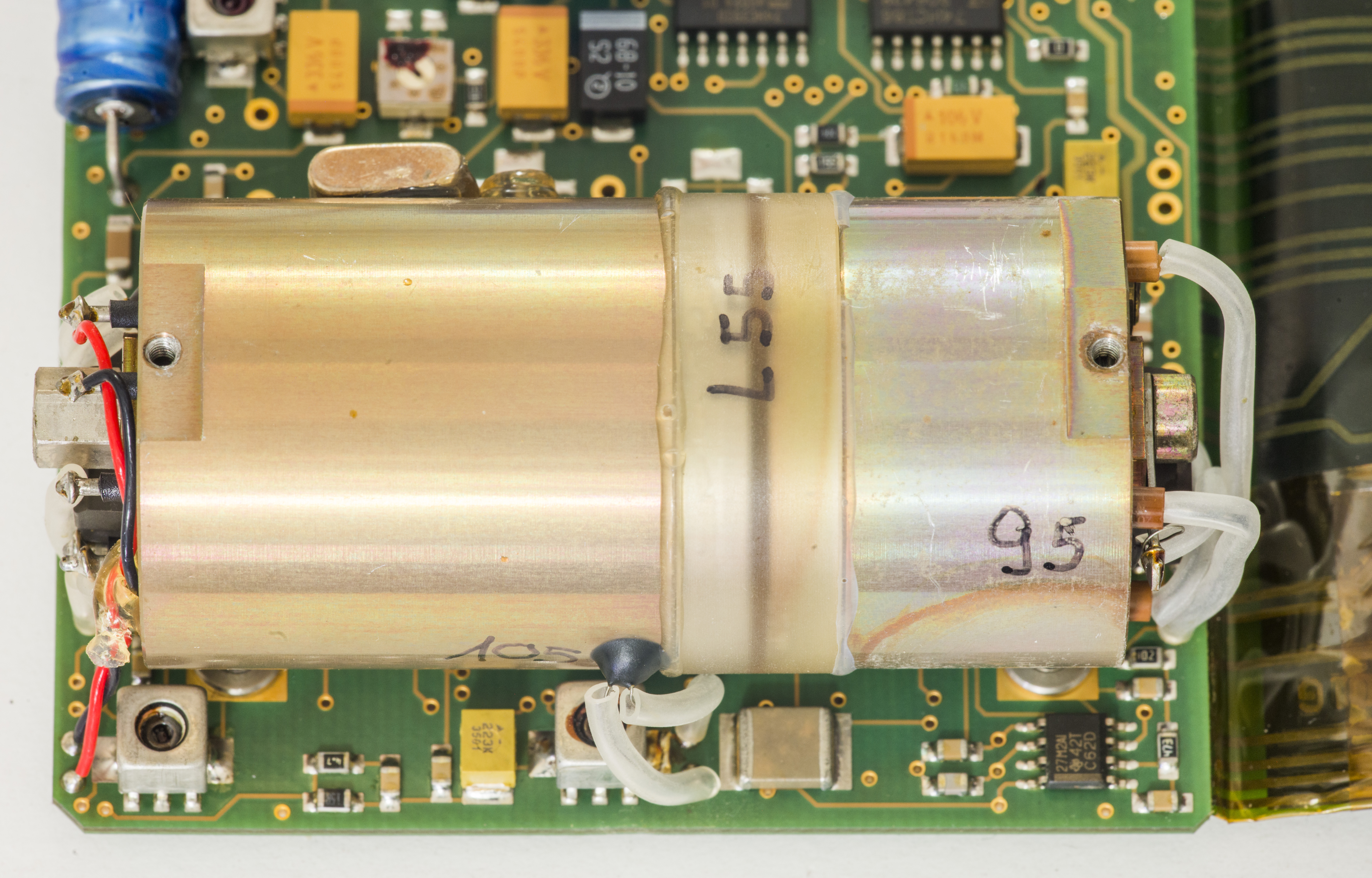
In darkness:
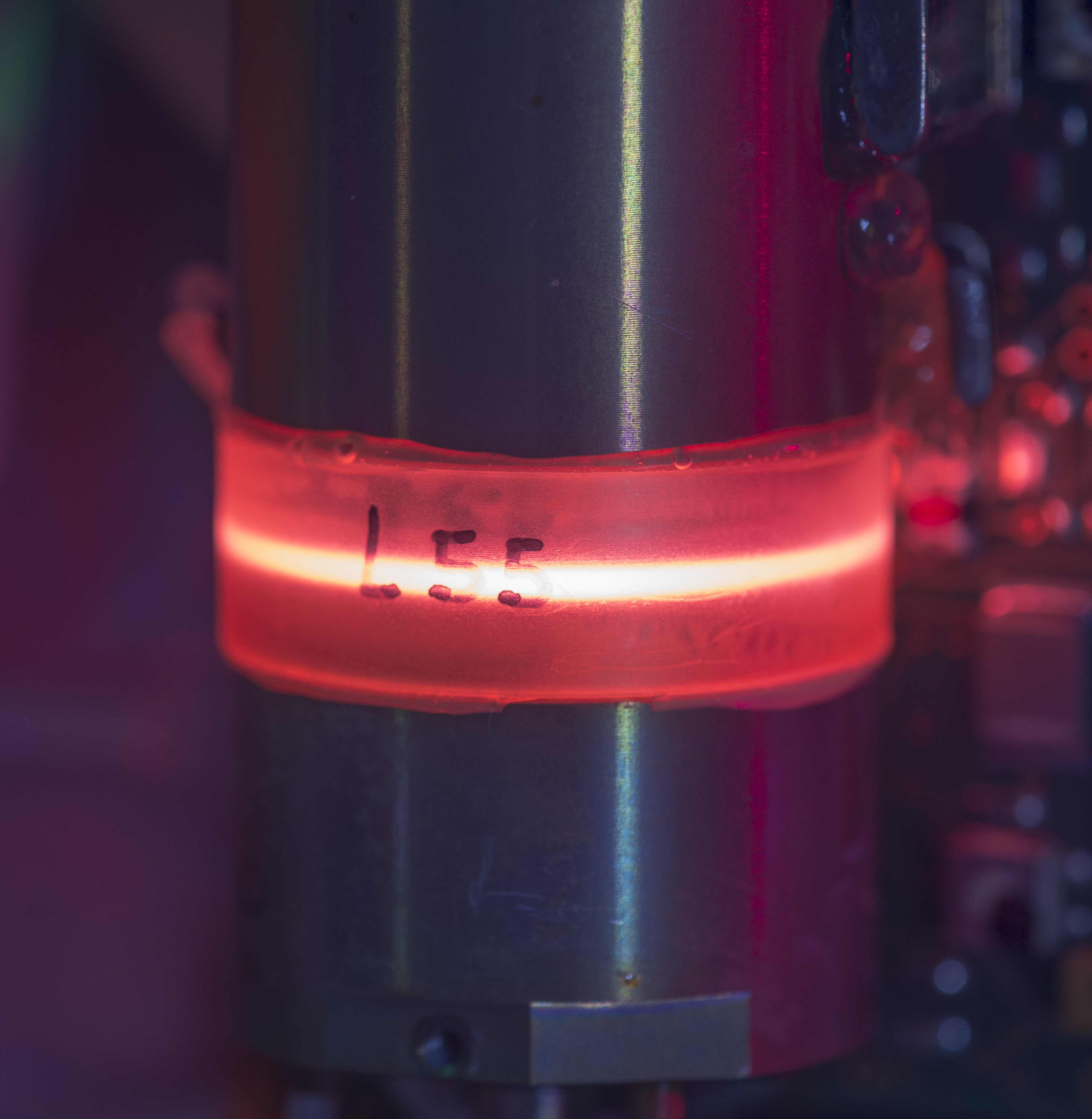
It’s not so bright, but definately visible in normal dim room lights.
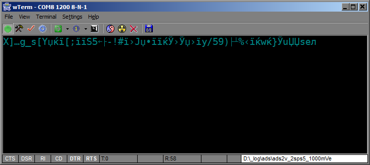
I tried connecting serial console to it, set speed 1200 bps, 8N1 mode, but only garble came out:
Where should I start this repair? I tried 3 modules , two drift hundreds of hertz in just seconds, compared to my 33120A, and lock never come low, while one is locking (signal goes low) but still drifts.
Chassis getting about +50-53°C, and power current stabilize at about 0.515Amps with +20VDC (don’t have powerful enough +24v source).
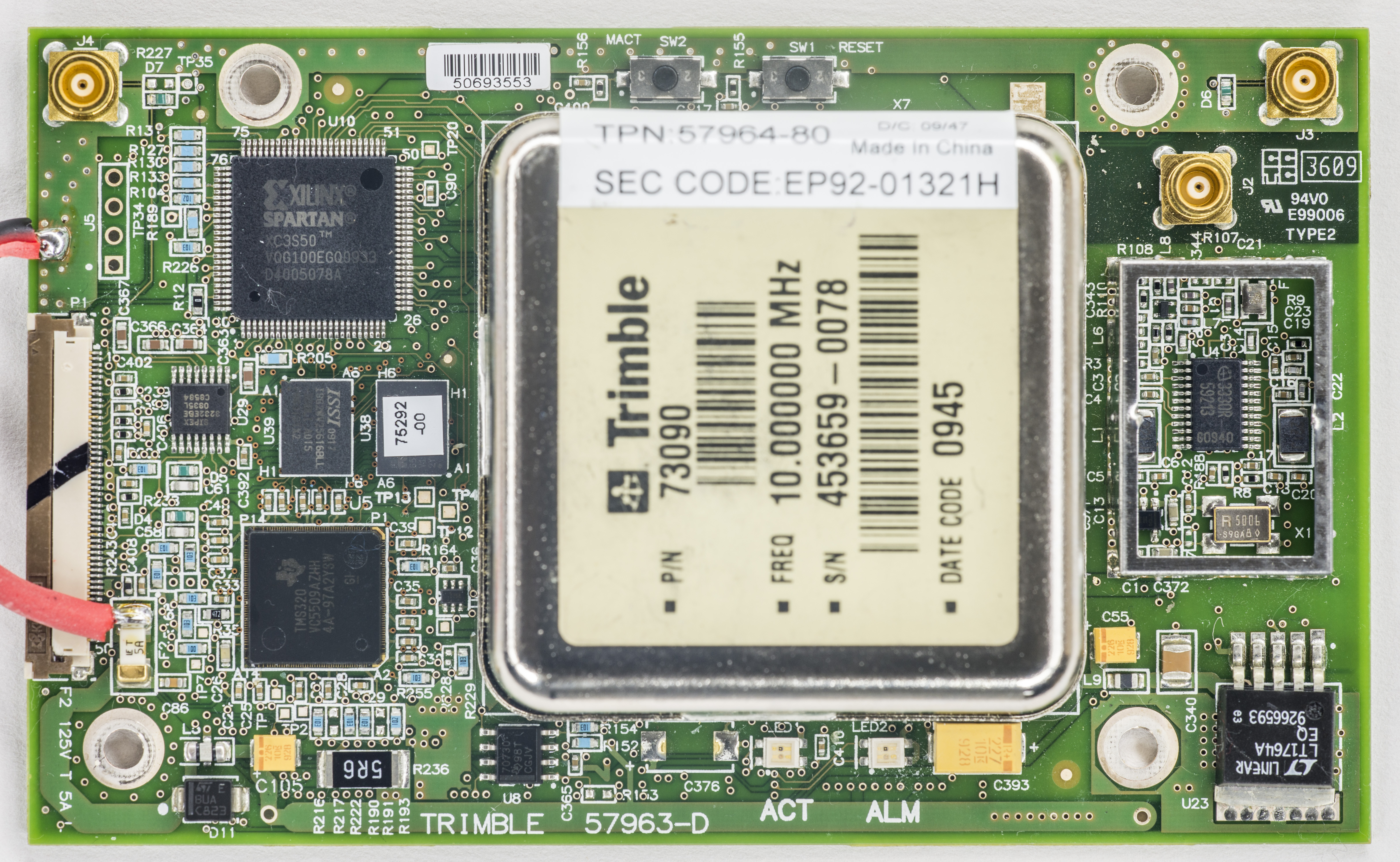
Trimble 57963-80 GPSDO module
This module will serve us as primary 10MHz frequency standard, and I’ll try to calibrate all rubidium modules to match GPSDO output exactly.


Shielded GPS receiver and +6V power input:
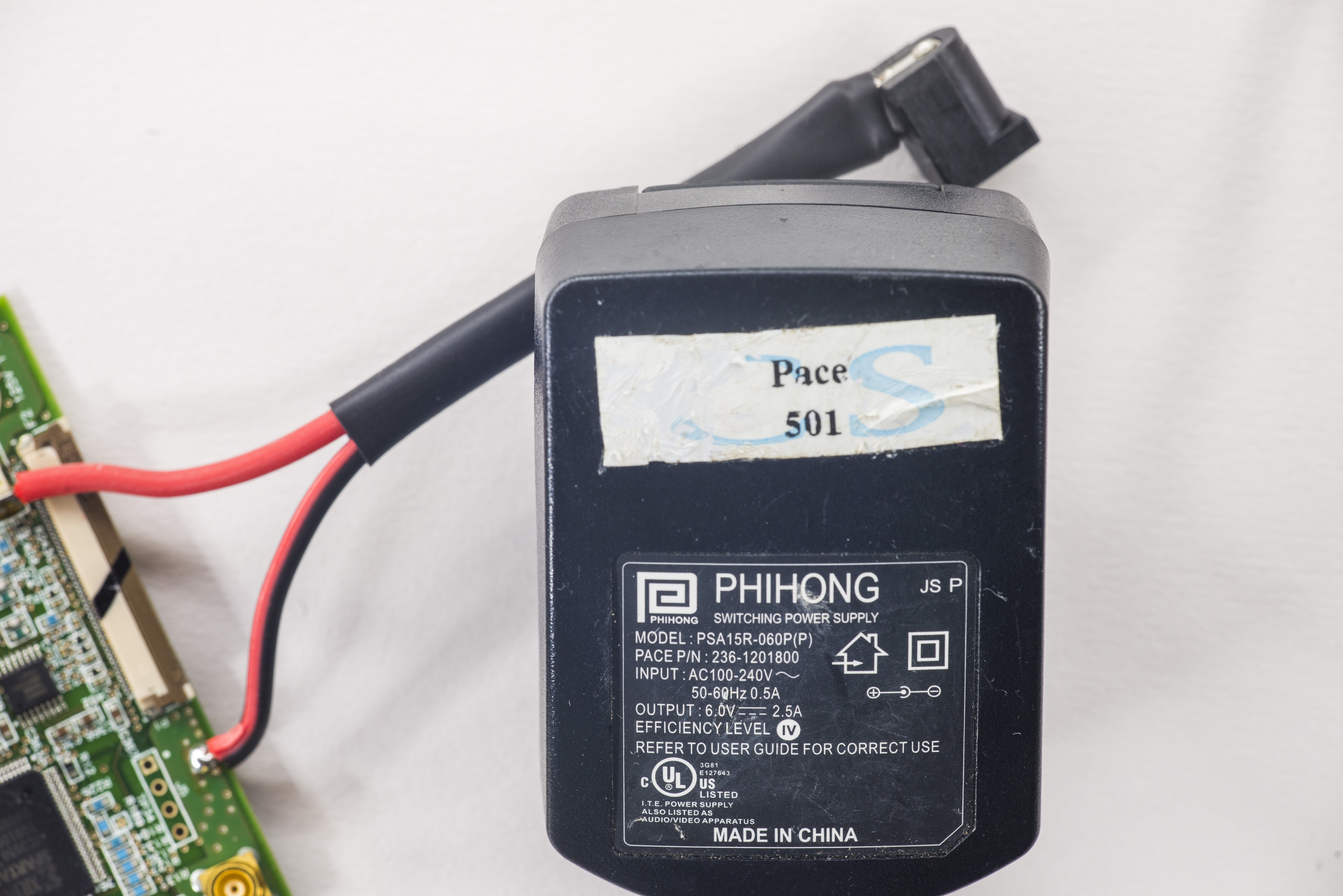
There is also included brick power supply, rated at 6VDC 2.5A output.
The receiver requires +5.5 V DC ±5% supply voltage. The power dissipation when cold started is ≤6 W. The power dissipation when warm started is ≤3W (active antenna power consumption not included).
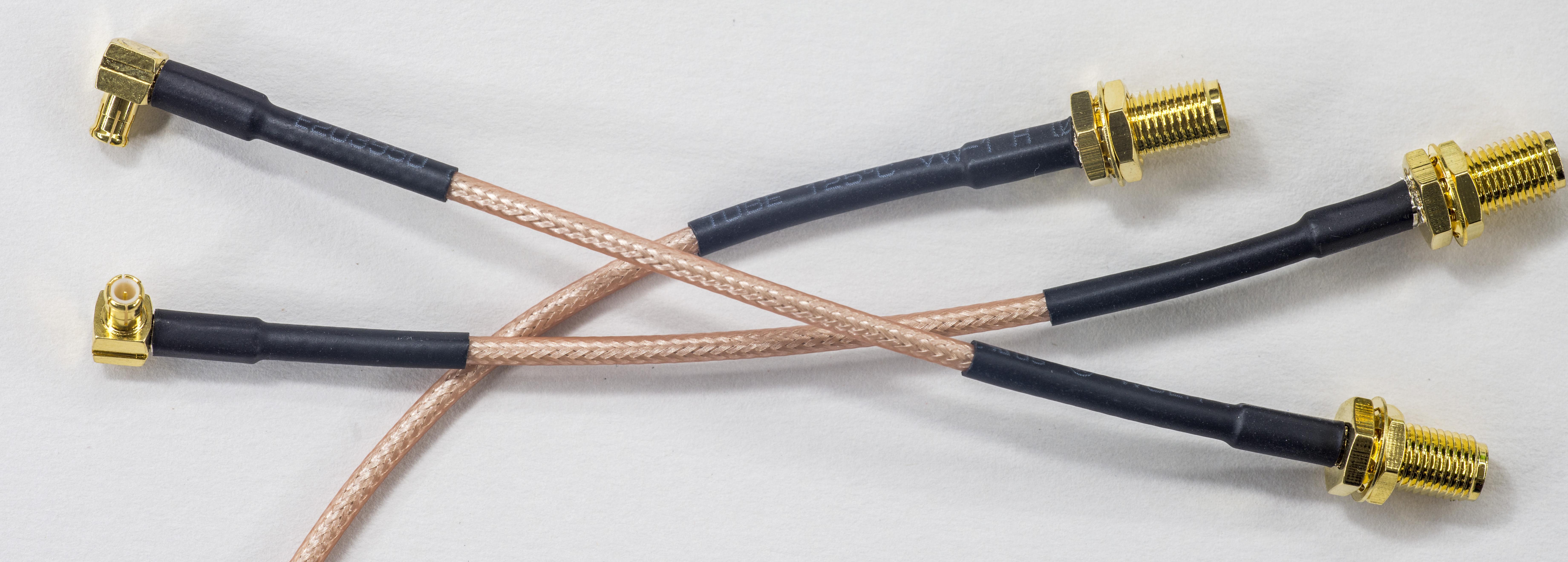
MCX to SMA-female adapters were included with module as well, but usually they are sold separately.
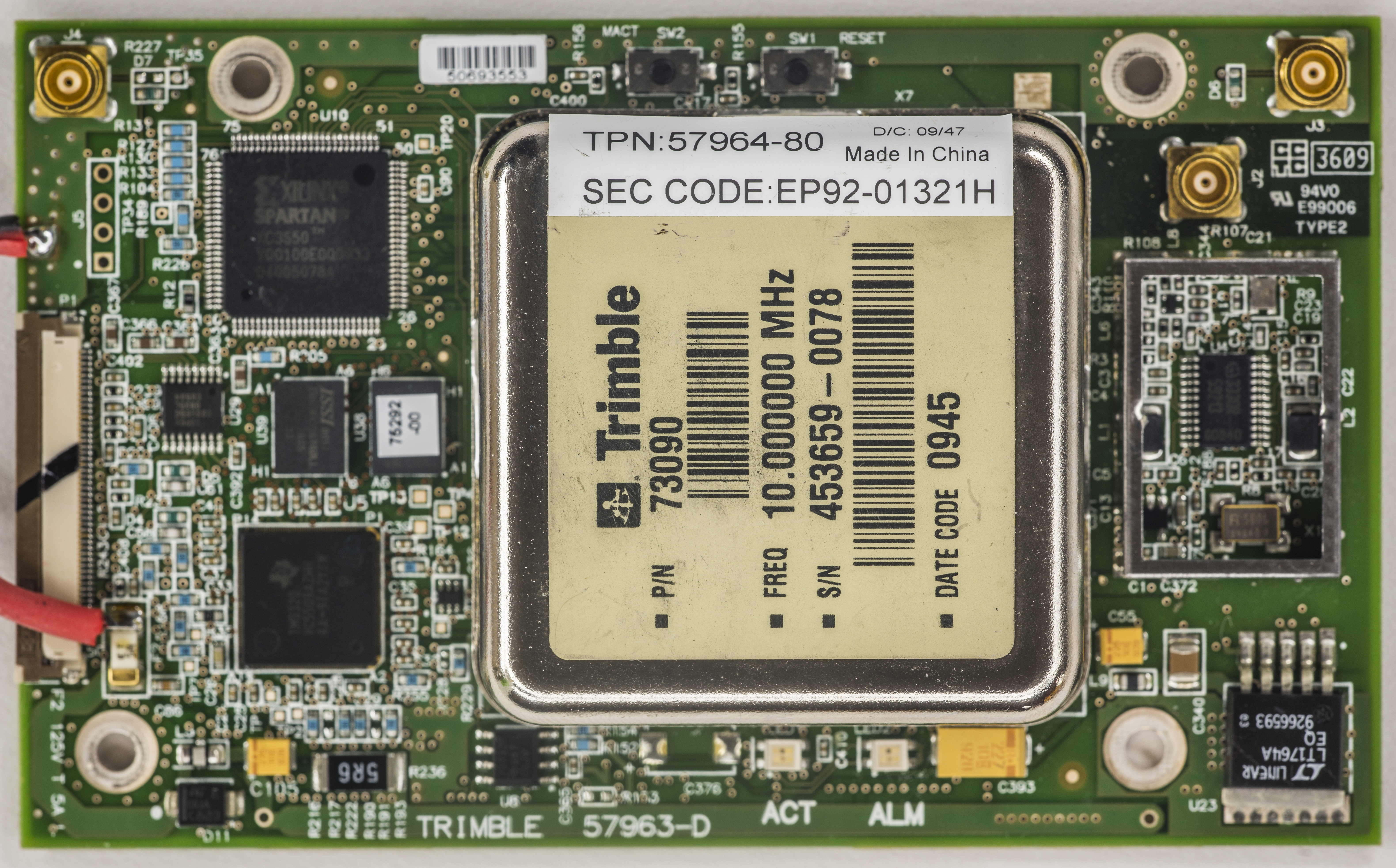

Module itself using Xilinx Spartan XC3S50 FPGA (U10), ISSI SDRAM, MXIC Flash with sticker 75292-00 and TI TMS320 processor.
GPSDO module provides one direct low-voltage (3.3V) LVTTL/CMOS compatible serial Input / Output (I/O) for the Time of Day (TOD) information. The RxD and TxD signals are driven directly by the UART on the Mini-T GG™. Interfacing these signals directly to a 3.3V LVTTL-level UART in the application circuitry provides direct serial communication without the need for RS-232 or RS-422 line drivers.
A second serial port with standard RS232 levels is provided as control and monitor console interface. The RX and TX signals are driven by RS232 line driver and can be connected to a standard RS232 COM port. The protocols on both serial ports can be either Trimble’s native TSIP protocol or the standardized NMEA protocol. RS232 interface is converted via SIPEX SP3232E to unpopulated J5 connector. Speed settings are 57600 8N1.
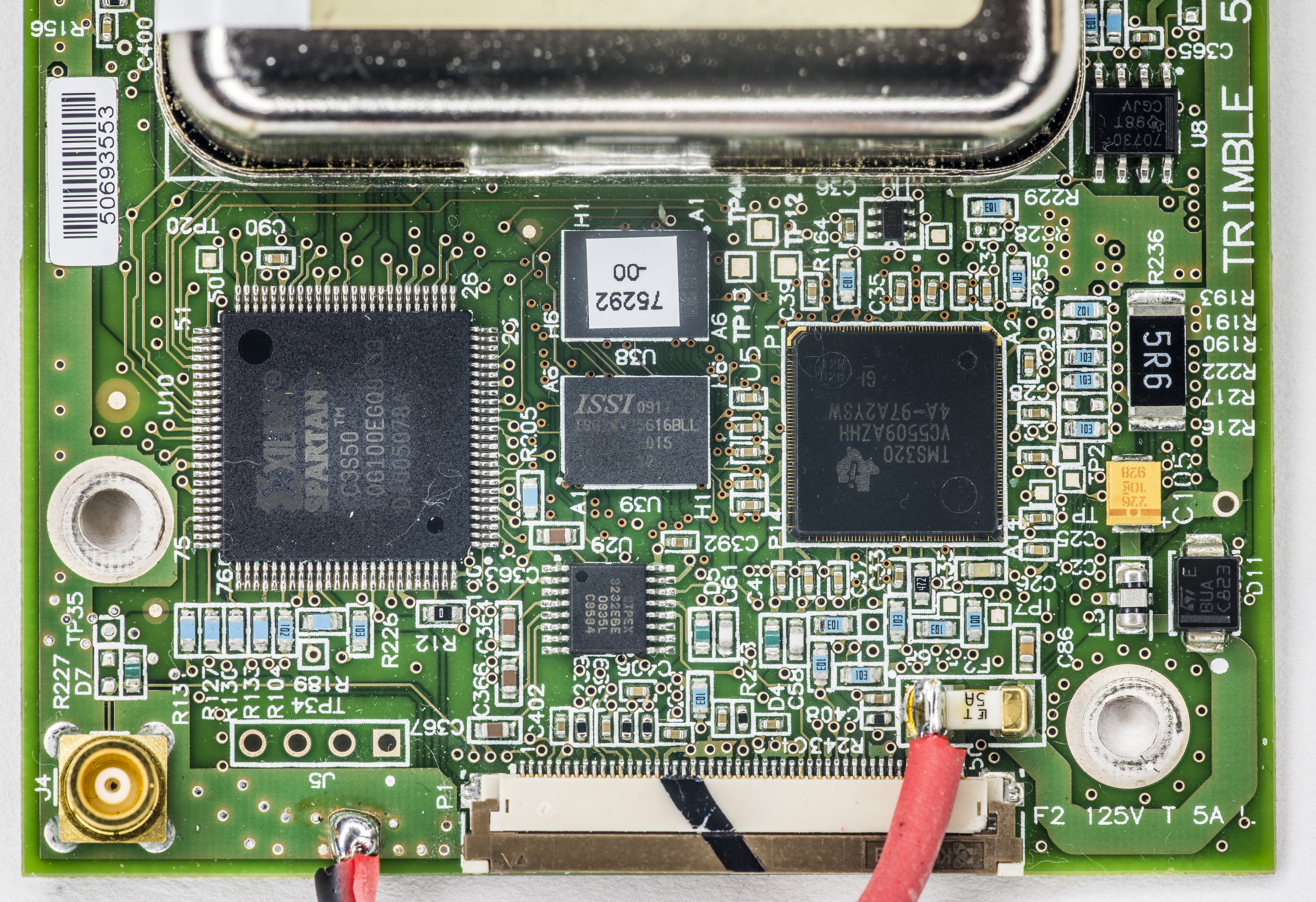
There is place for unused SMT connector on bottom side with unknown purpose and no labels. Perhaps JTAG port for debug?
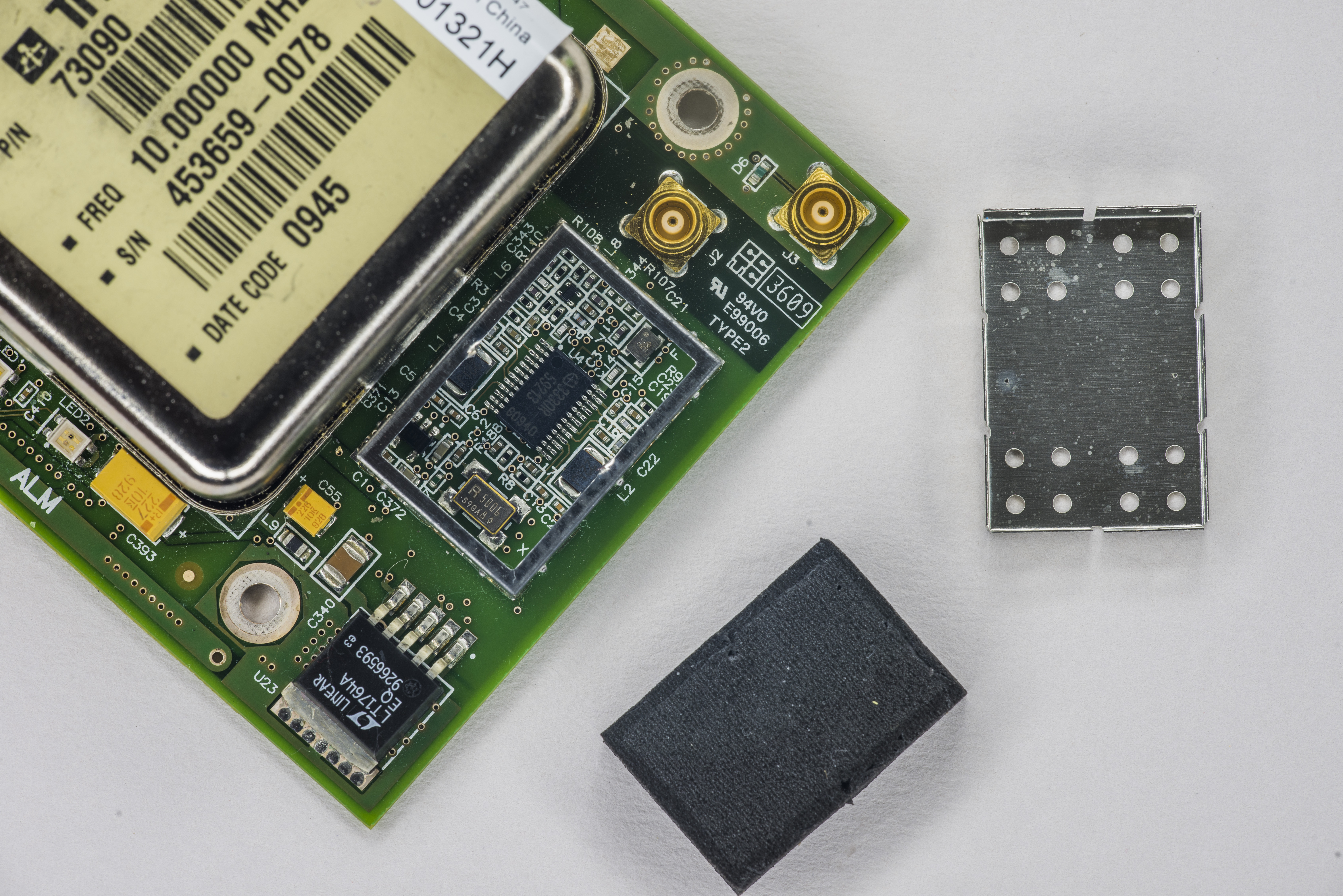
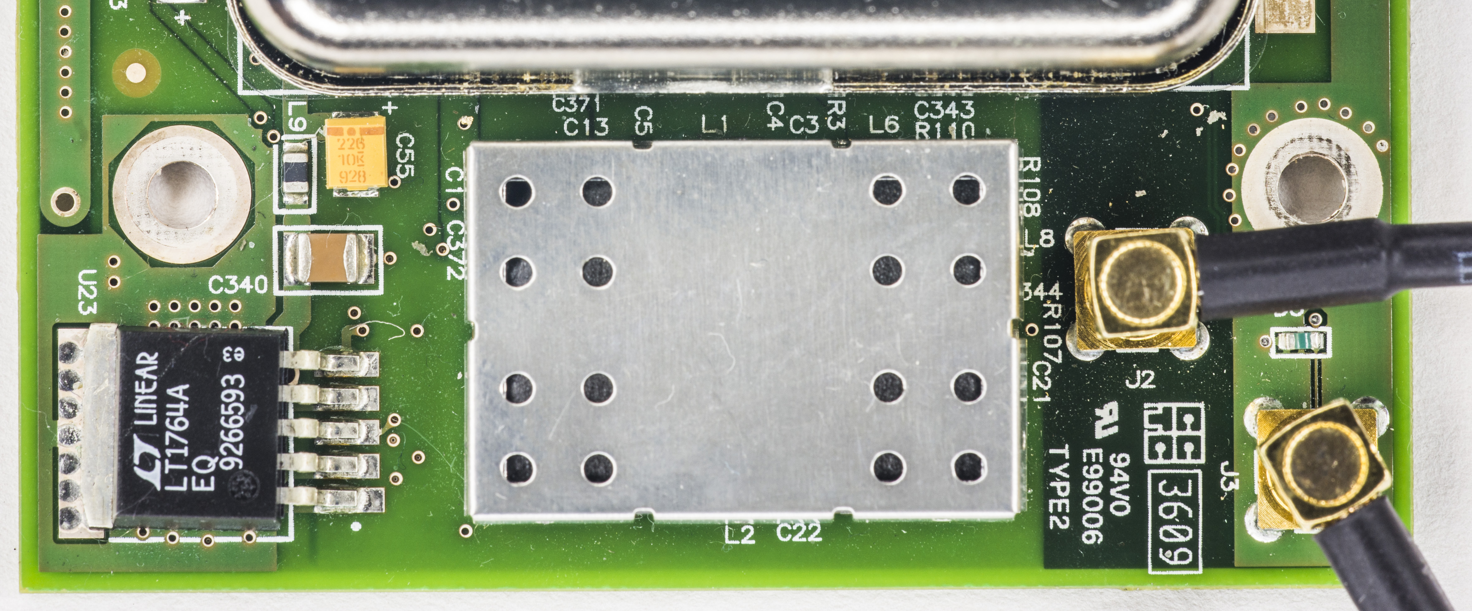
Closer look on Linear 5VDC LDO and GPS chipset in shielded area:

All connected, and shield back in place:
Antenna Voltage Feed conditions are +5.0V drive voltage, with current monitoring:
| Antenna Open | Below the 8mA range |
| Antenna Short | Above 150mA |
| Antenna Current Limiting | Above 190mA |
The antenna power output is only specified up to 55 mA. The reason for the 55 mA upper limit is basically the voltage drop. Exceeding 55 mA will not damage the receiver, but the antenna supply might be insufficient.
GPS signals can only be received on a direct line of sight between antenna and satellite. The antenna should see as much as possible of the total sky. Seen from the northern hemisphere of the earth, more satellites will be visible in the southern direction rather than in northern direction. The antenna should therefore have open view to the southern sky. If there are obstacles at the installation site, the antenna should be placed south of the obstacles, preferably, in order not to block sky-view to the south. If the installation site is in the southern hemisphere of the earth, then the statements above are reversed – more satellites will be visible in the northern direction. Near to the equator, it doesn’t matter.
Partial sky visibility causes often poor DOP values due to the geometry of the visible satellites in the sky. If the receiver can only see a small area of the sky, the DOP has a high degree of uncertainty and will be worse compared to a condition with better geometric distribution. It may happen that a receiver is seeing 6 satellites, all close together, and still get a much worse DOP than a receiver which sees 4 satellites, but all in different corners of the sky. The receiver’s DOP filter rejects fixes with high DOP (high uncertainty), it can take longer to get the first acceptable fix if sky visibility is partly obstructed.
Also it’s better to locate antenna at roof, as multipath reflections occurs when the GNSS signals are reflected by objects, such as metallic surfaces, walls and shielded glass for example. The antenna should not be placed near a wall, window or other large vertical objects if it can be avoided.
The 10 MHz output on the MCX connector is a sinusoidal analog frequency. It should be terminated with a 50 Ω load. The output power into 50 Ω is typically 7 dBm (min 5 dBm, max 9 dBm). The frequency output is phase-locked with the PPS pulse. The Phase Noise of the 10 MHz frequency output is:
- -90dBc/Hz
 1Hz
* -120dBc/Hz
10Hz - -135dBc/Hz
 100Hz
* -145dBc/Hz
>1KHz
Also extra to 10 MHz output on the MCX connector, there’s a digital low-voltage 3.3V LVTTL logic level 10 MHz frequency output clock available on the 50-pin FPC connector.
After connection of UART-USB dongle to serial interface on module (pins 11 and 12 on SIPEX SP3232E converter): some interface logs were captured:
UCCM-P >*IDN?
TRIMBLE,57964-80,50693553,V2.0.1.6-01
Some stats data:
UCCM-P >SYST:STAT?
-------------------------------------------------------------------------------
 57964-80     serial number  50693553     firmware ver  2.0.1.6-01 LINK    mode
 -------------------------------------------------------------------------------
 Reference Status __________________________   Reference Outputs _______________
 XX Ref 8KHz 0: [LOS]
 XX Ref 8KHz 1: [LOS]                          TFOM     2            FFOM      3
 XX Ref 8KHz 2: [LOS]                          UCCM A Status[OCXO WARMUP]
 XX Ref 8KHz 3: [LOS]
 XX GPS: [No Ref]
 ACQUISITION .................................................[GPS 1PPS Invalid]
 Tracking: 0 ____   Not Tracking: 12 _______   Time ____________________________
 PRN  El  Az  C/N   PRN  El  Az                GPS      00:01:29 (?) 22 Aug 1999
                      5  -- ---
                     20  -- ---                ANT DLY  -1 ns
                     22  -- ---                Position ________________________
                      2  -- ---                MODE     Hold
                     12  -- ---
                     13  -- ---                LAT      N  25:57:29.658
                     30  -- ---                LON      E 119:31:14.779
                     32  -- ---                HGT               +39.66 m (MSL)
                      1  -- ---
                     18  -- ---
                     26  -- ---
                     29  -- ---
 ELEV MASK  5 deg
 -------------------------------------------------------------------------------
Coordinates are somewhere in China, so those are old ones, likely location of seller test site, where GPSDO was checked. Need connect GPS antenna to get actual signal first, before we can get module going.
              - UCCM Slot STATE-

1-1. #Now ACTIVE STATUS ---------------- [OCXO Warm]
1-2. #Before ACTIVE STATUS ------------- [OCXO Warm]
2-1. #Reference Clock Operation -------- [Not Used]
2-2. #Current Reference Type ----------- [GPS]
2-3. #Current Select Reference --------- [GPS 1PPS]
2-4. #Current Reference Status --------- [Ref LOS]
     #GPS STATUS ----------------------- [Available]
     #Priority Level ------------------- [LINK > GPS]
     #ALARM STATUS
     #H/W FAIL [ GPS LINK ]
     #OPERATION ALARM ------------------ [Antenna]
3-1. #PLL STATUS ----------------------- [DISABLE]
3-2. #Current PLL MODE ----------------- [OFFSET OBSERVATION MODE]
Command POSSTAT reply
UCCM-P >POSSTAT

---------------------------------------------
 08/22/1999  00:09:40
---------------------------------------------
 Position: LAT(N  25:57:29.658) LON(E 119:31:14.779) H(         +39.66 m MSL)
---------------------------------------------
 Geometry: PDOP(0.0) HDOP(0.0) VDOP(0.0)
 num of visible sats >  0
 num of sats tracked >  0
  -------- Receiver Channel State --------
 CH  0 > SateID(25) TrackMode(tracking ) SigValue( 0)
 CH  1 > SateID(19) TrackMode(tracking ) SigValue( 0)
 CH  2 > SateID(22) TrackMode(tracking ) SigValue( 0)
 CH  3 > SateID(02) TrackMode(tracking ) SigValue( 0)
 CH  4 > SateID(31) TrackMode(tracking ) SigValue( 0)
 CH  5 > SateID(07) TrackMode(tracking ) SigValue( 0)
 CH  6 > SateID(28) TrackMode(tracking ) SigValue( 0)
 CH  7 > SateID(17) TrackMode(tracking ) SigValue( 0)
 CH  8 > SateID(15) TrackMode(tracking ) SigValue( 0)
 CH  9 > SateID(04) TrackMode(tracking ) SigValue( 0)
 CH  10 > SateID(24) TrackMode(tracking ) SigValue( 0)
 CH  11 > SateID(09) TrackMode(tracking ) SigValue( 0)
---------------------------------------------
 Rcvr Status(1):
---------------------------------------------
 Antenna Voltage:  5000.00mV   , Antenna Current:     2.13mA
That is it for now.
Actual GPSDO readout
Here’s updated GPS reading after antenna is connected:
UCCM-P >SYST:STAT?
-------------------------------------------------------------------------------
57964-80     serial number  50693553     firmware ver  2.0.1.6-01 LINK    mode
-------------------------------------------------------------------------------
Reference Status __________________________   Reference Outputs _______________
XX Ref 8KHz 0: [LOS]
XX Ref 8KHz 1: [LOS]                          TFOM     2            FFOM      0
XX Ref 8KHz 2: [LOS]                          UCCM A Status[ACTIVE]
XX Ref 8KHz 3: [LOS]
>> GPS: [phase:+2.3E-08]
ACQUISITION ...................................................[GPS 1PPS Valid]
Tracking: 3 ____   Not Tracking: 8 ________   Time ____________________________
PRN  El  Az  C/N   PRN  El  Az                GPS      04:25:00     18 Apr 2016
 31  51  11   39    14  56 125
 32  57 134   37    22  28 274                ANT DLY  15 ns
 29  29  62   34    10   7 176                Position ________________________
                    26  67 271                MODE     Hold
                    25   7  42
                    16  40 238                LAT      N  25:00:xx.xxx
                     3  16 302                LON      E 121:28:xx.xxx
                    27   6 193                HGT               +73.84 m (MSL)


ELEV MASK  5 deg
-------------------------------------------------------------------------------
STAT data:
UCCM-P >STAT

               - UCCM Slot STATE-

1-1. #Now ACTIVE STATUS ---------------- [Master]
1-2. #Before ACTIVE STATUS ------------- [OCXO Warm]
2-1. #Reference Clock Operation -------- [Not Used]
2-2. #Current Reference Type ----------- [GPS]
2-3. #Current Select Reference --------- [GPS 1PPS]
2-4. #Current Reference Status --------- [Good Accuracy & Stable]
     #GPS STATUS ----------------------- [Available]
     #Priority Level ------------------- [LINK > GPS]
     #ALARM STATUS
     #H/W FAIL [ LINK ]
     #OPERATION ALARM ------------------ [LINK ]
3-1. #PLL STATUS ----------------------- [ENABLE]
3-2. #Current PLL MODE ----------------- [NORMAL 2 MODE]
Useful references to read
Modified: July 3, 2017, 5:56 p.m.
References
- EEVBlog : TEMEX/SpectraTime LPFRS/LPRO repair
- [time-nuts] Temex LPFRS-01 / LPRO rubidium reference repair
- Spectratime / Temex LPFRS-01 / LPRO teardown photos
- Trimble : Time Reference and Frequency Reference Modules
- Trimble Mini-T : Multi-GNSS Disciplined Clock
- EEVBlog : Symmetricom GPSDO / 10MHz reference
- G313 ABS chassis page
- Raspberry Pi as a Stratum-1 NTP Server
- Raspberry Flavored Time
- Tipok's blog : GPSDO 50-pin pinout reverse