This analog generator provide 50 ohm terminated frequency output, in range from 5kHz to 3.0GHz.
We got unit with errors -330,-313 during self-test and will try to repair it.
It have these features :
- Ideal EMS signal source with specified frequency range from 5 kHz
- AM, FM, pulse modulation
- FM DC with high carrier frequency accuracy
Overview
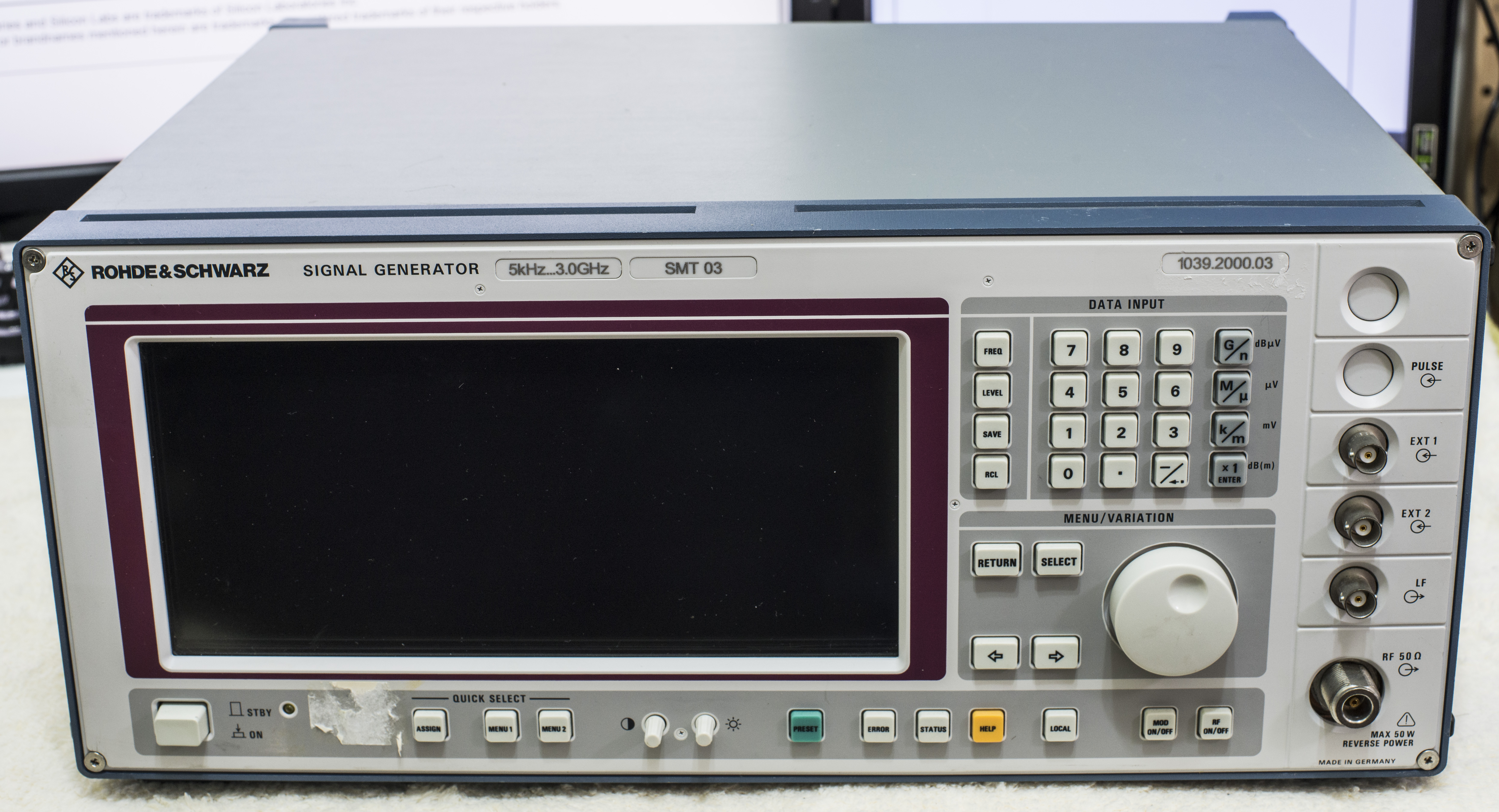
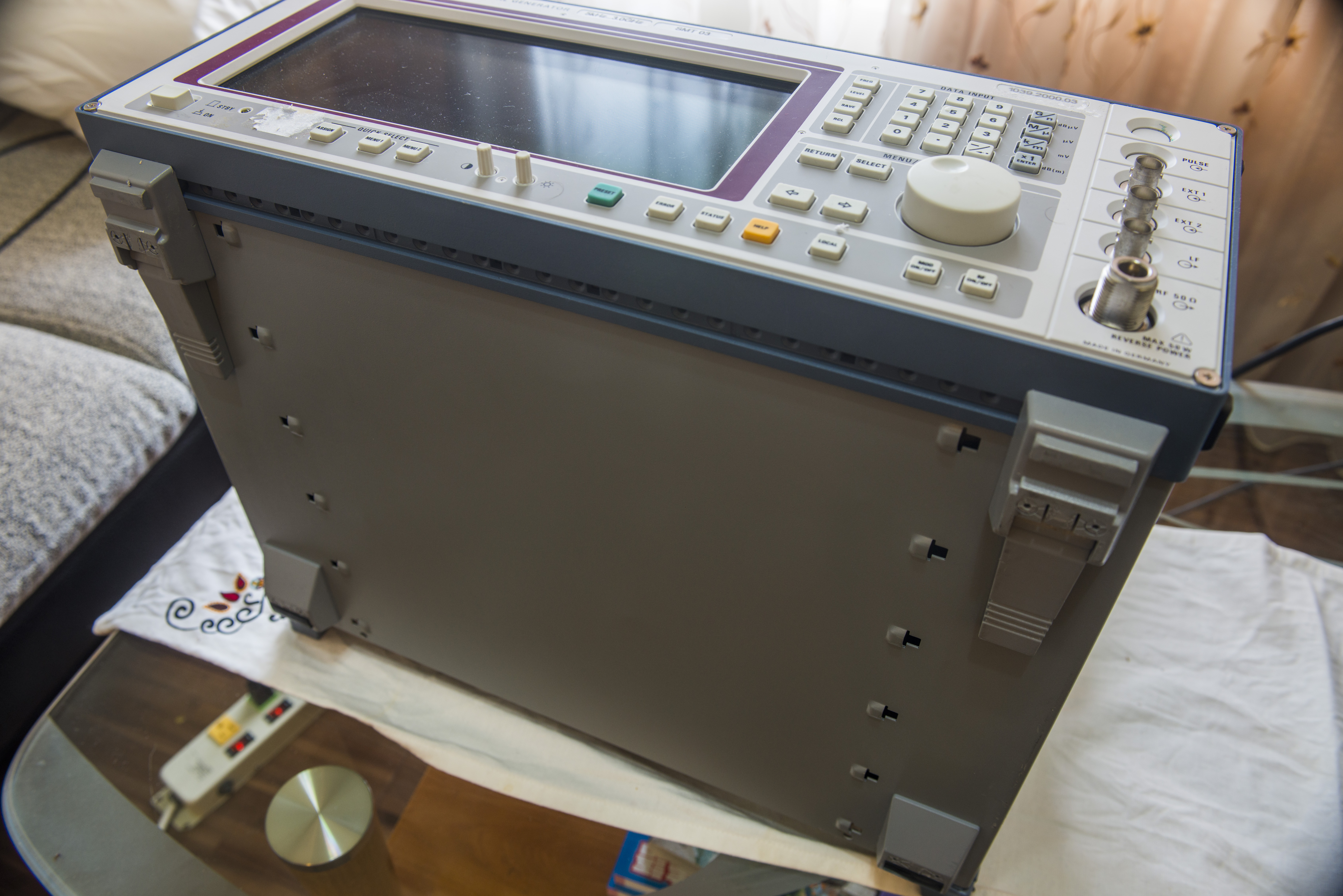
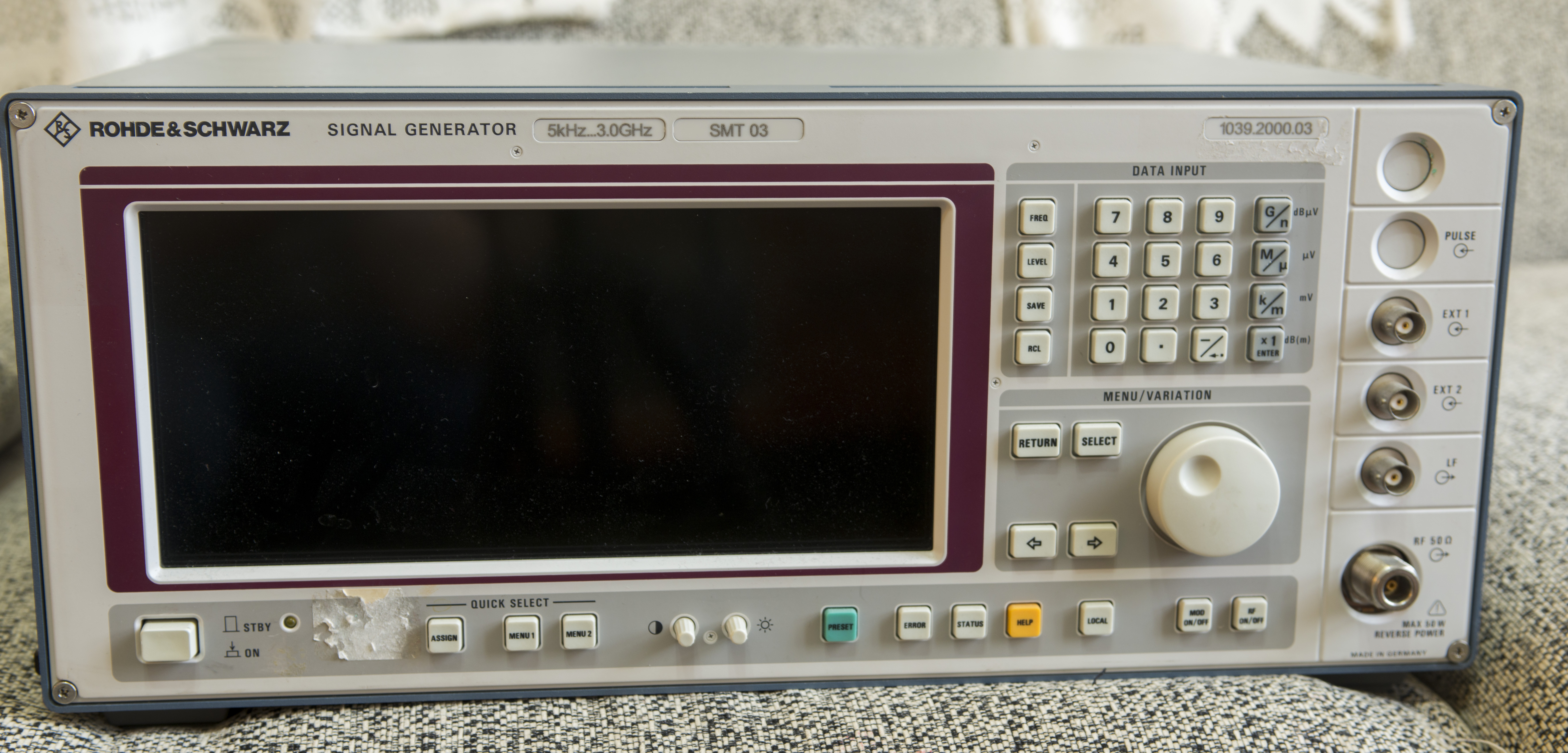
Front panel have nice soft-feel buttons and enormous size display (as for generator). Front display glass is metallized to shield internals as well!
And no, it’s not touch.
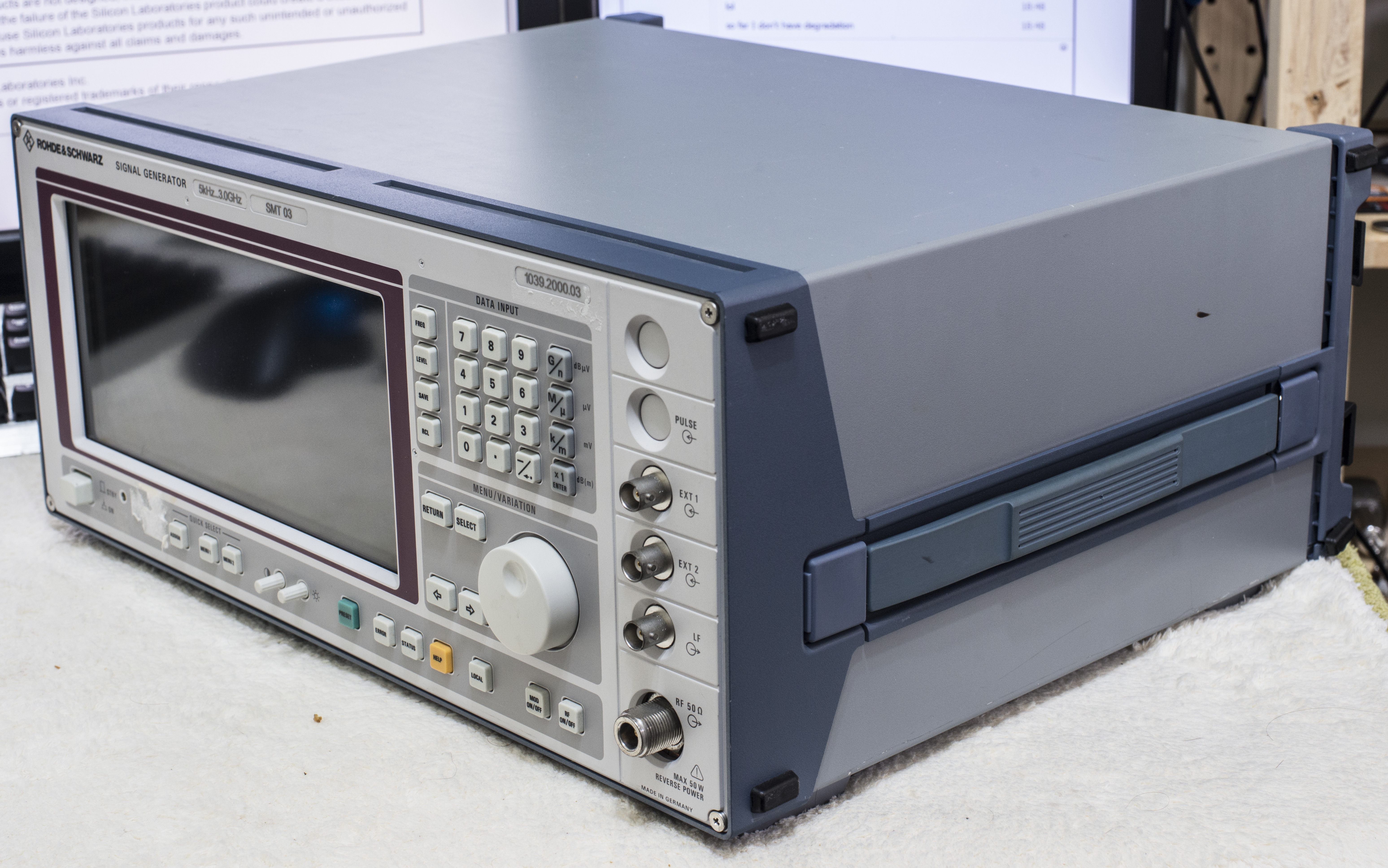
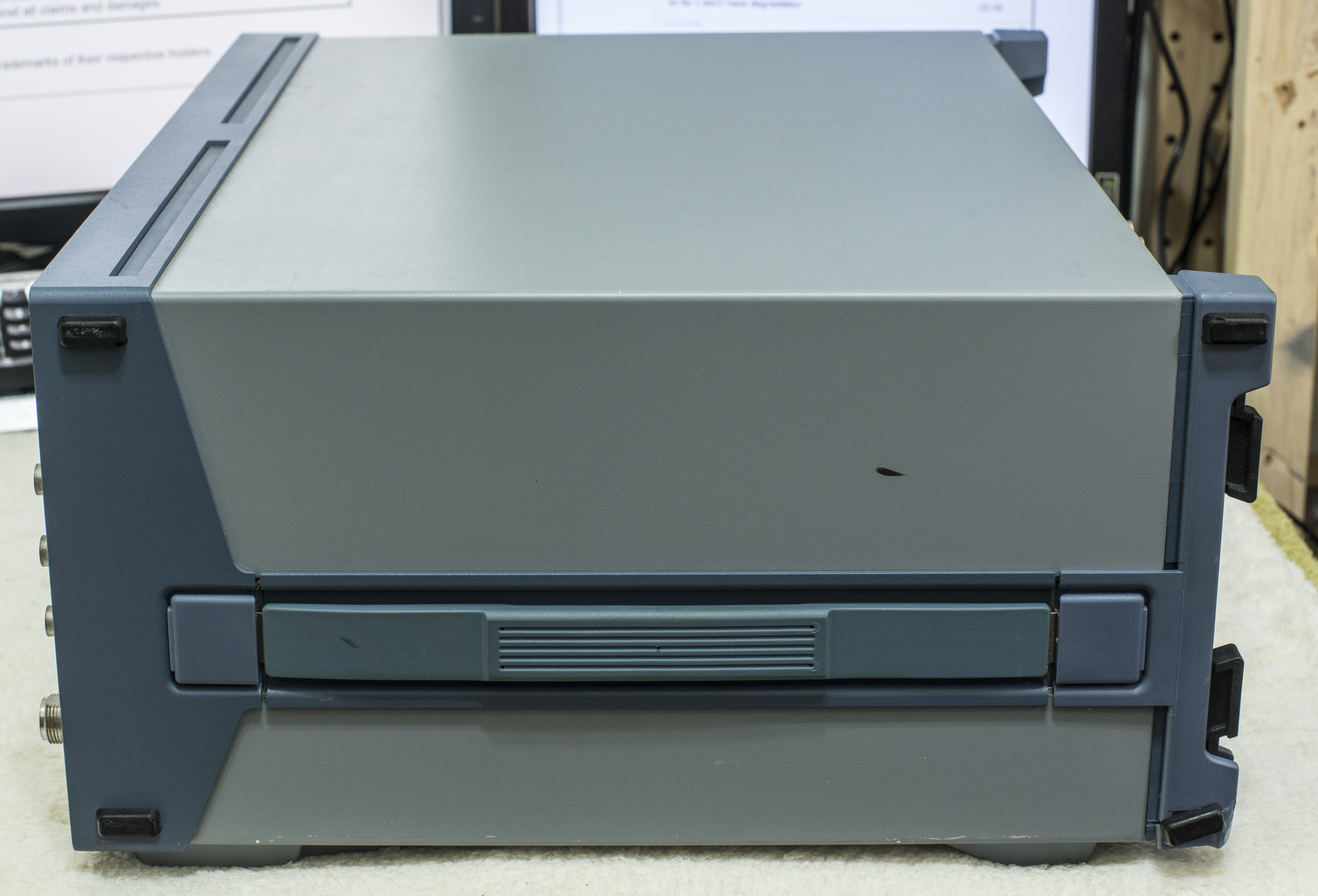
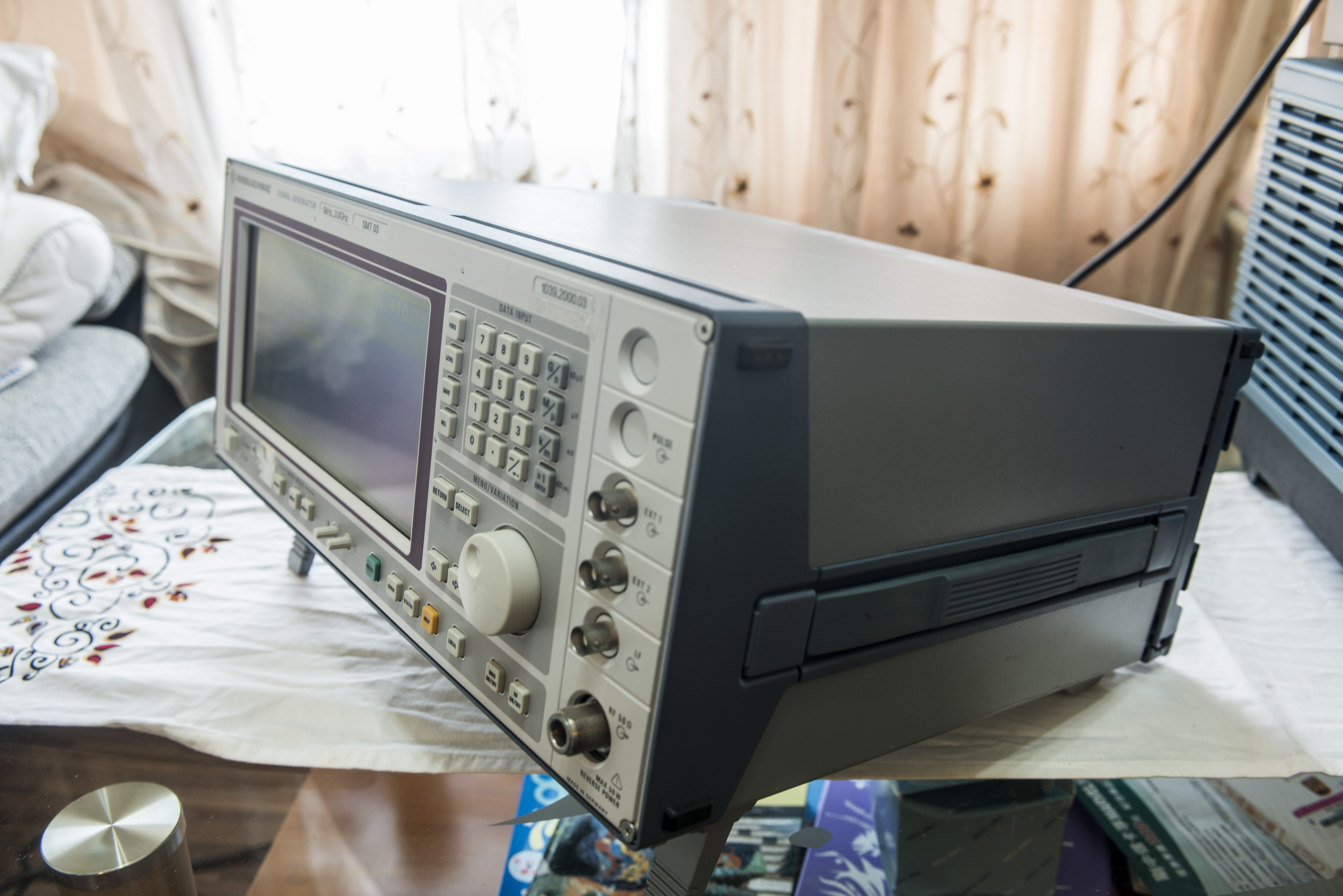
Unit is pretty heavy and bulky, but short :)
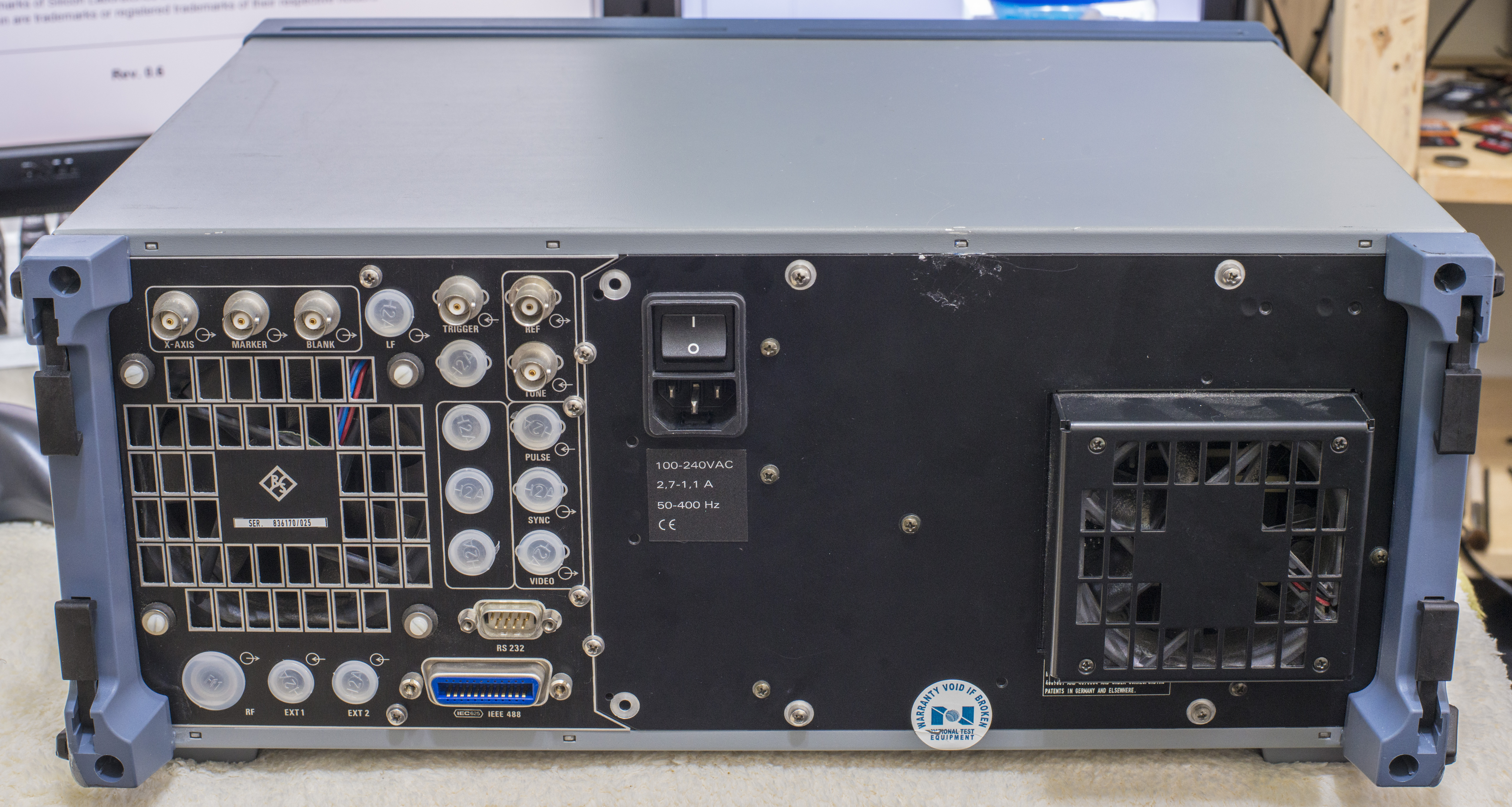
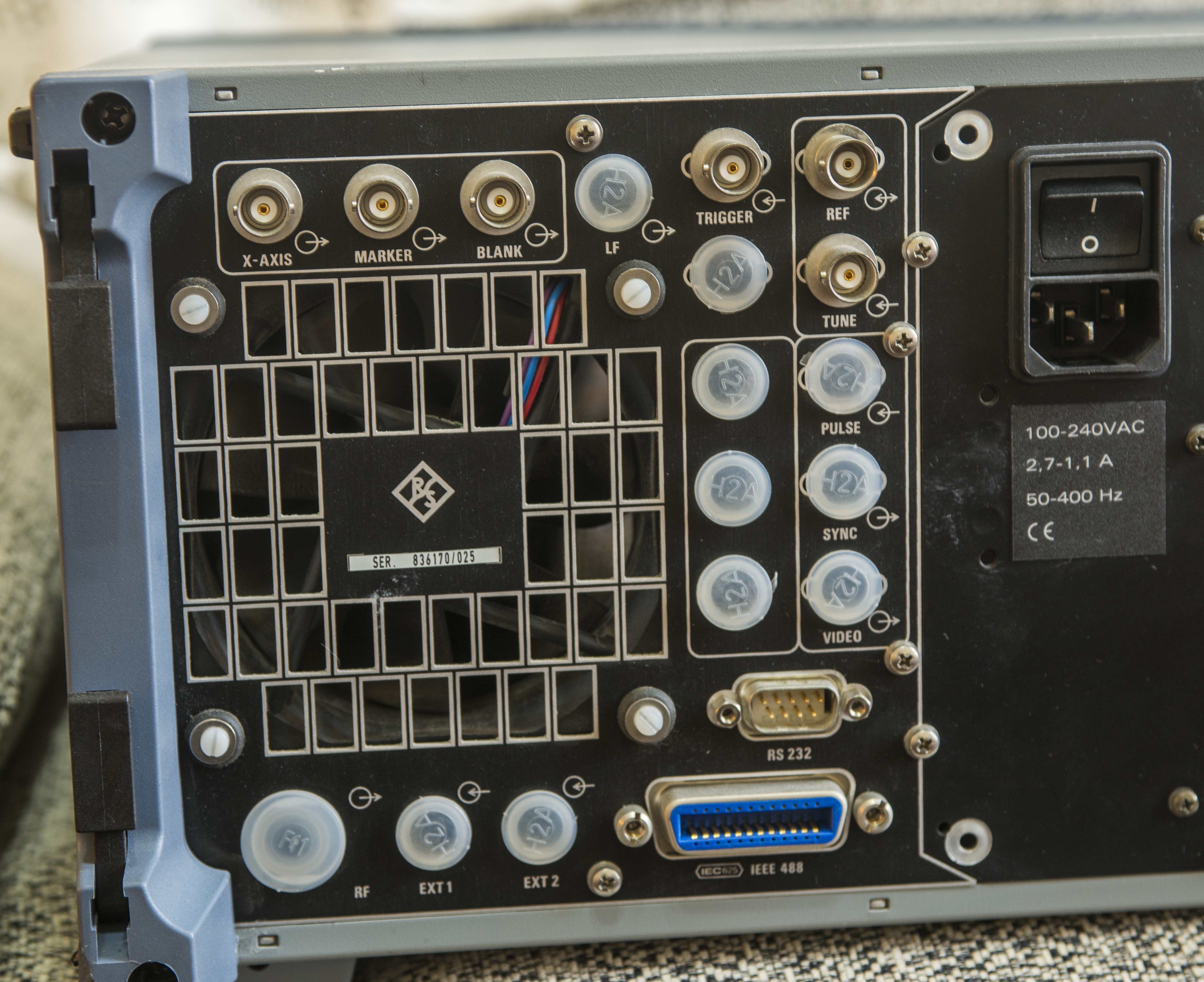
Back have some coax connectors, RS232, GPIB and two medium noise fans.
Let’s turn it on to see what’s wrong..
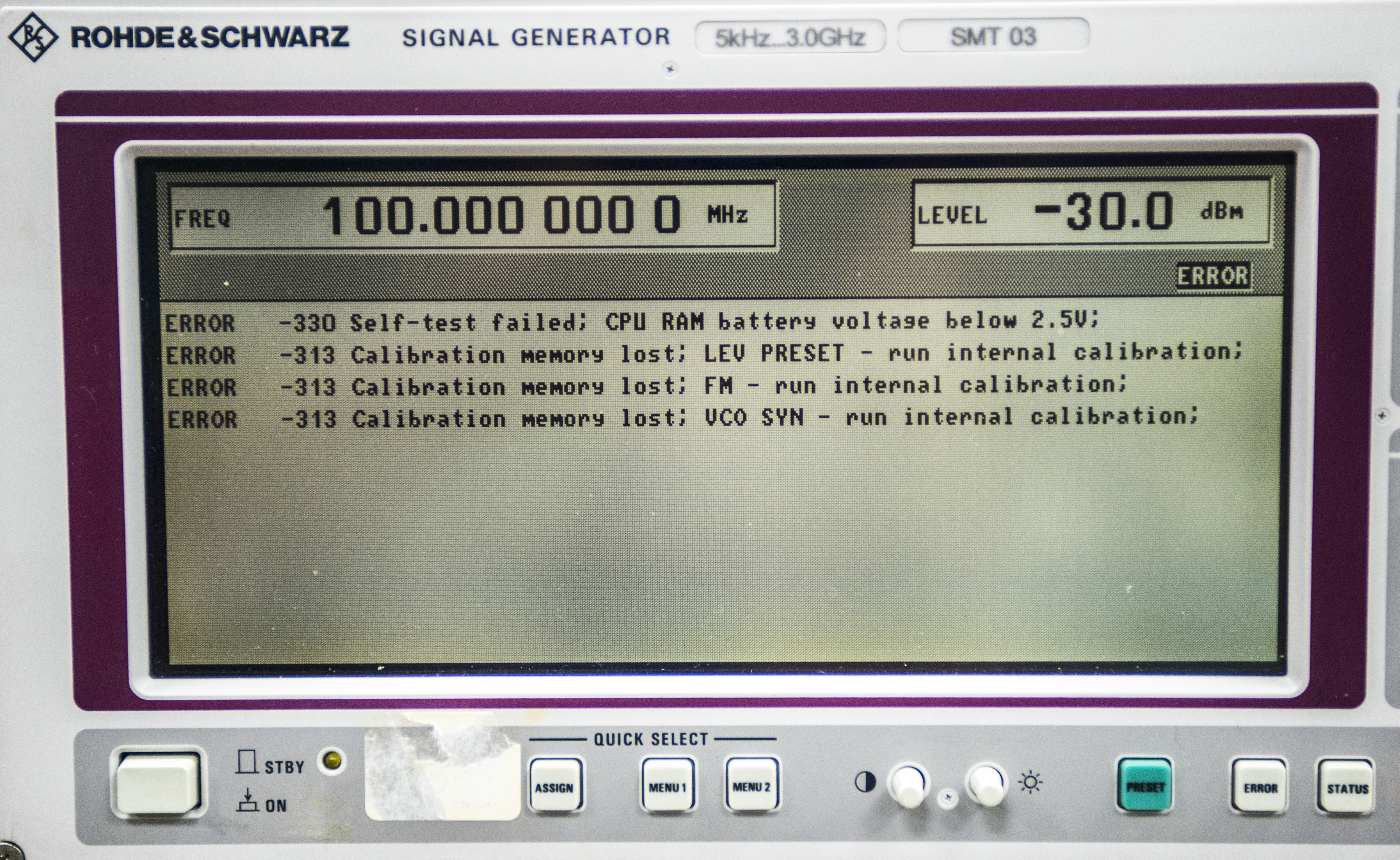
Aha, looks like it have sick battery, just like old 7000-series TDSes from Tektronix…
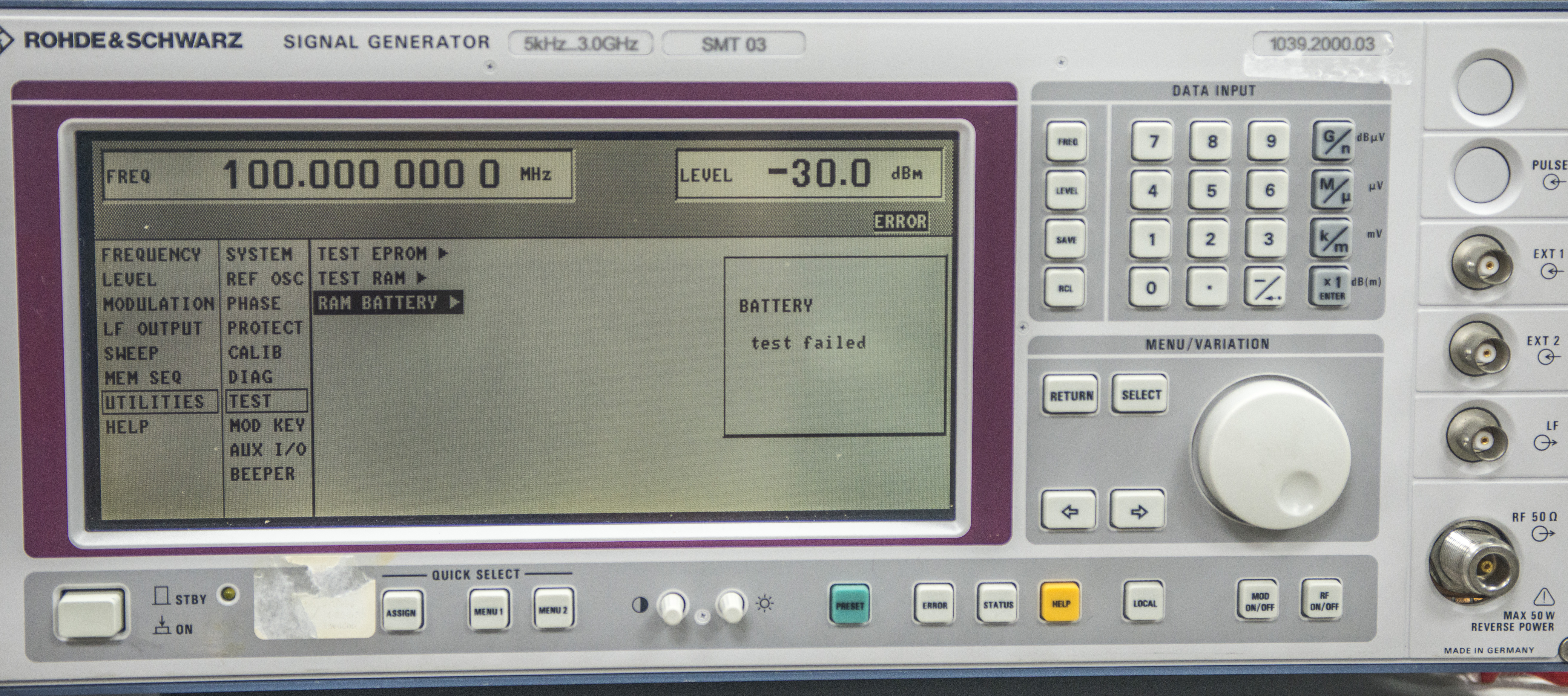
Self diags agree to that..
Repair
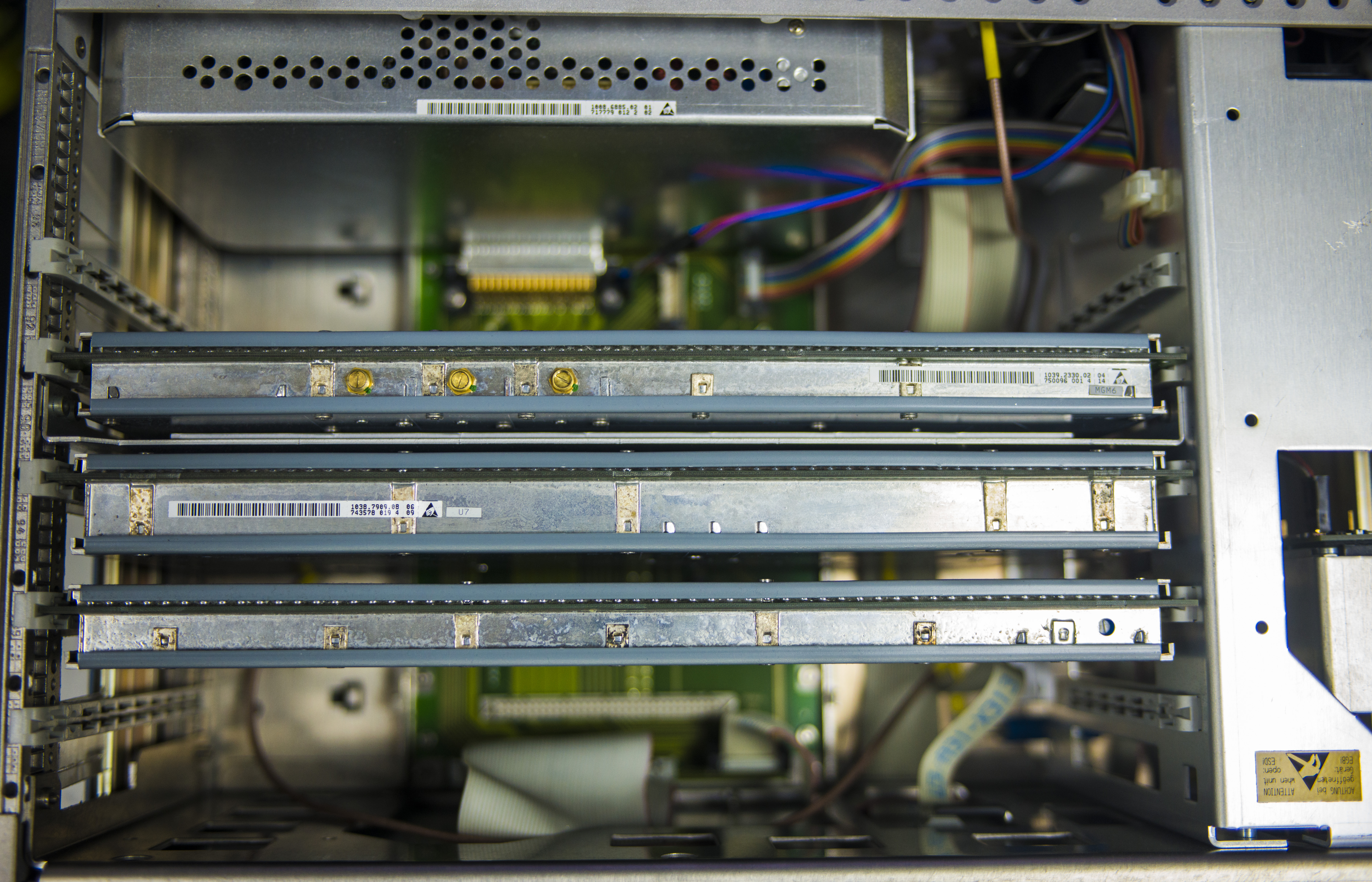
Nice robust chassis, modular construction. Well made, very clean and tidy design. There are empty slots for options. My unit is just basic configuration,
so have lots of emptyness :)
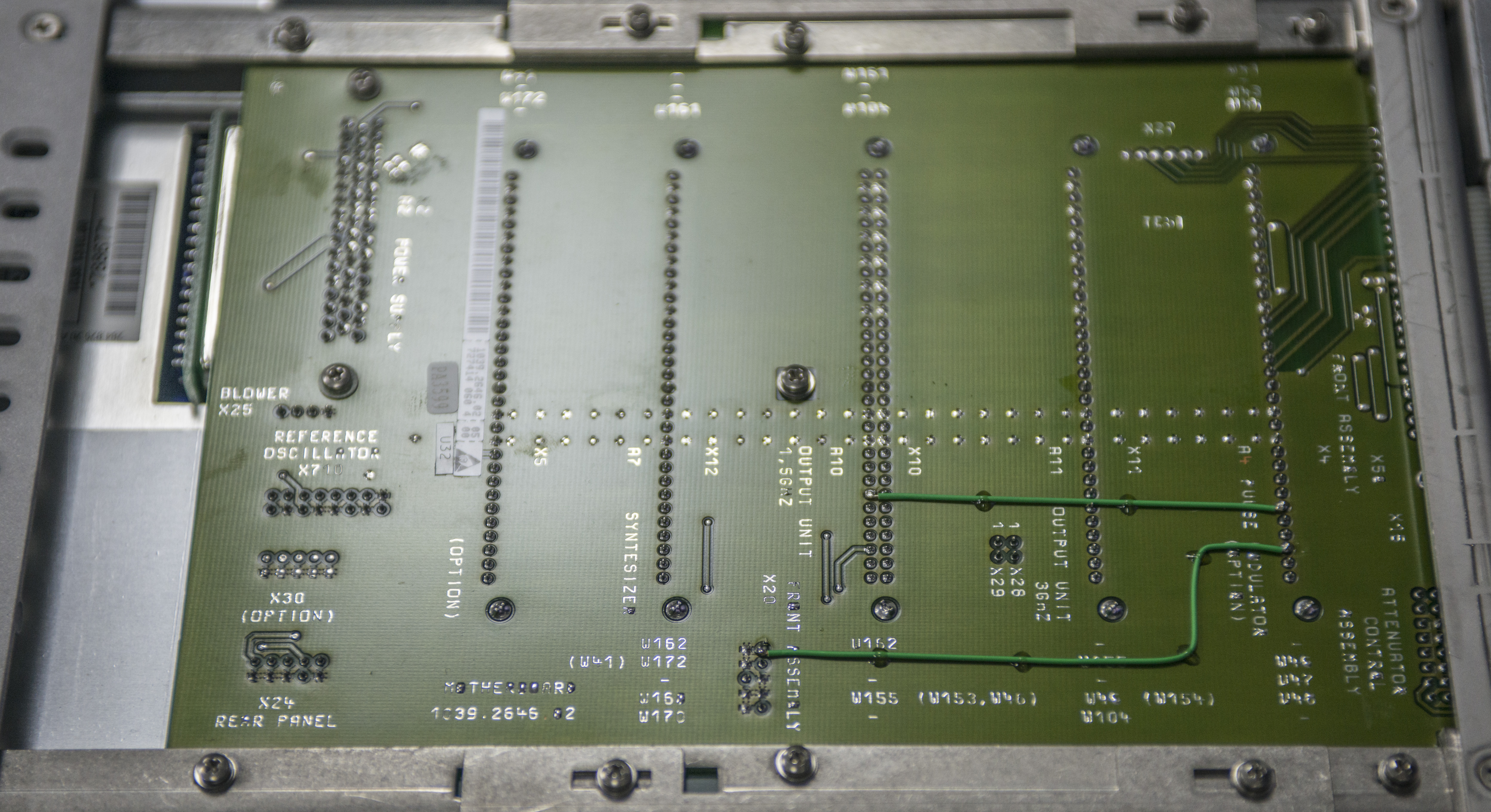
Bottom side shows us backplane interconnect with few bodged wires.
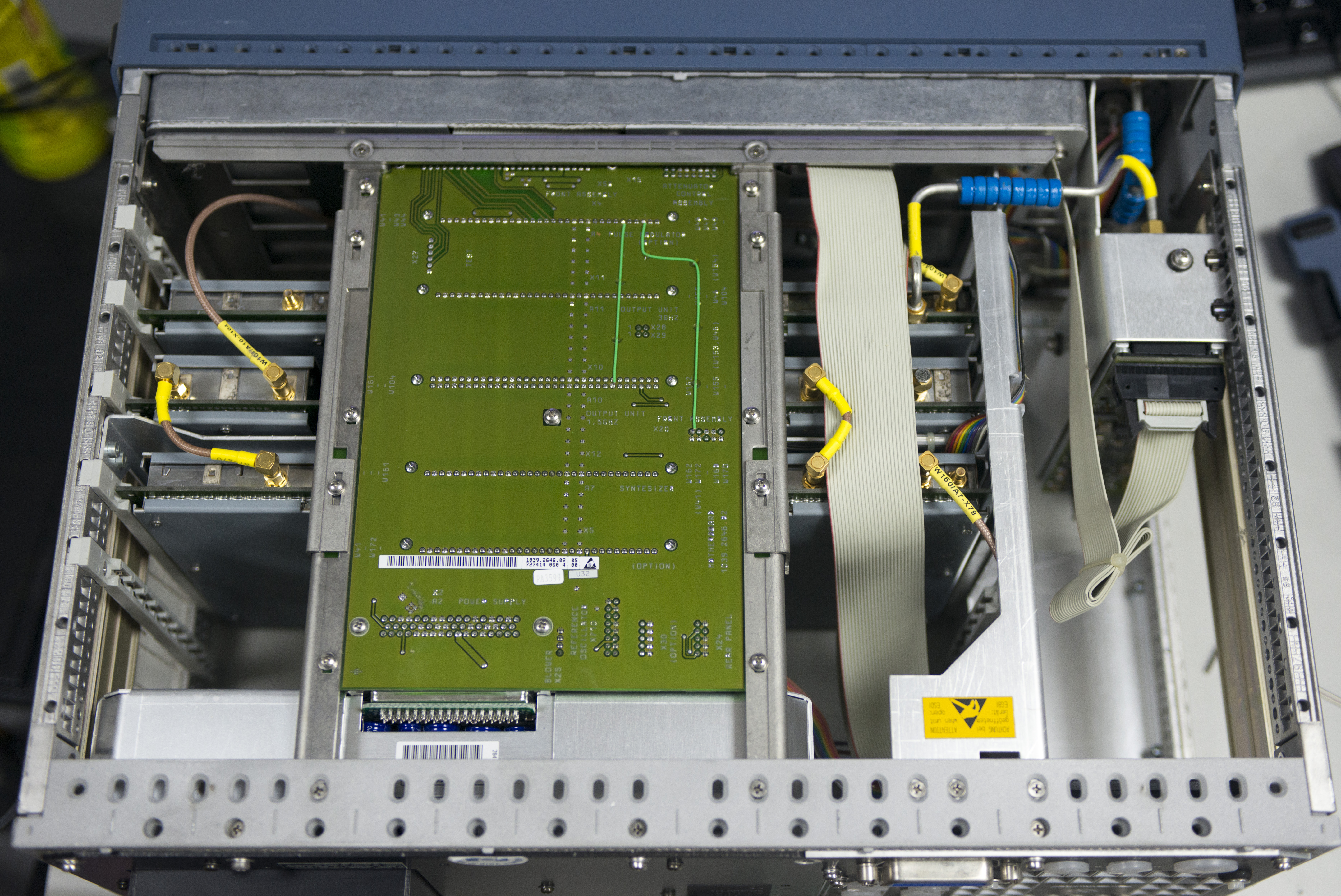
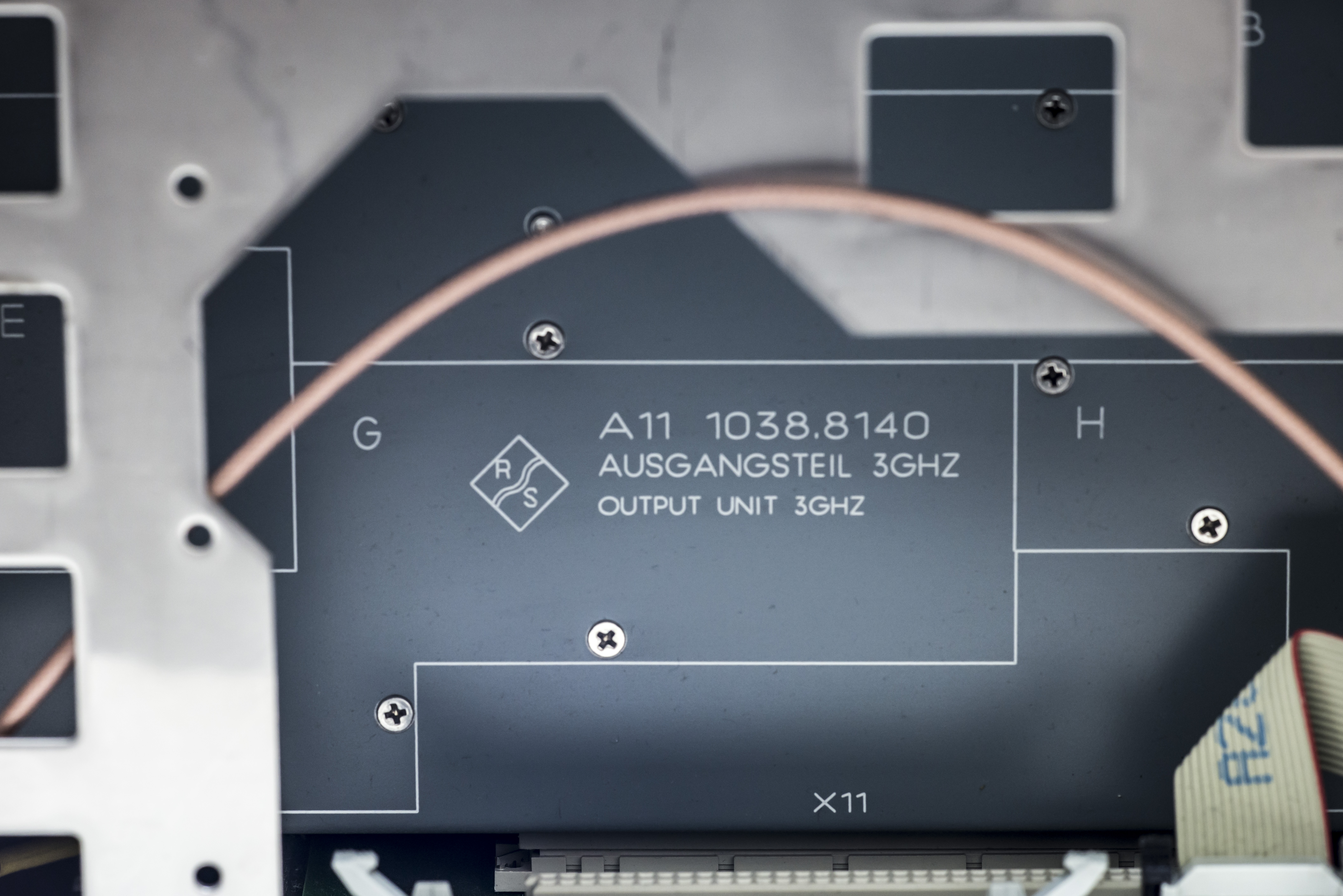
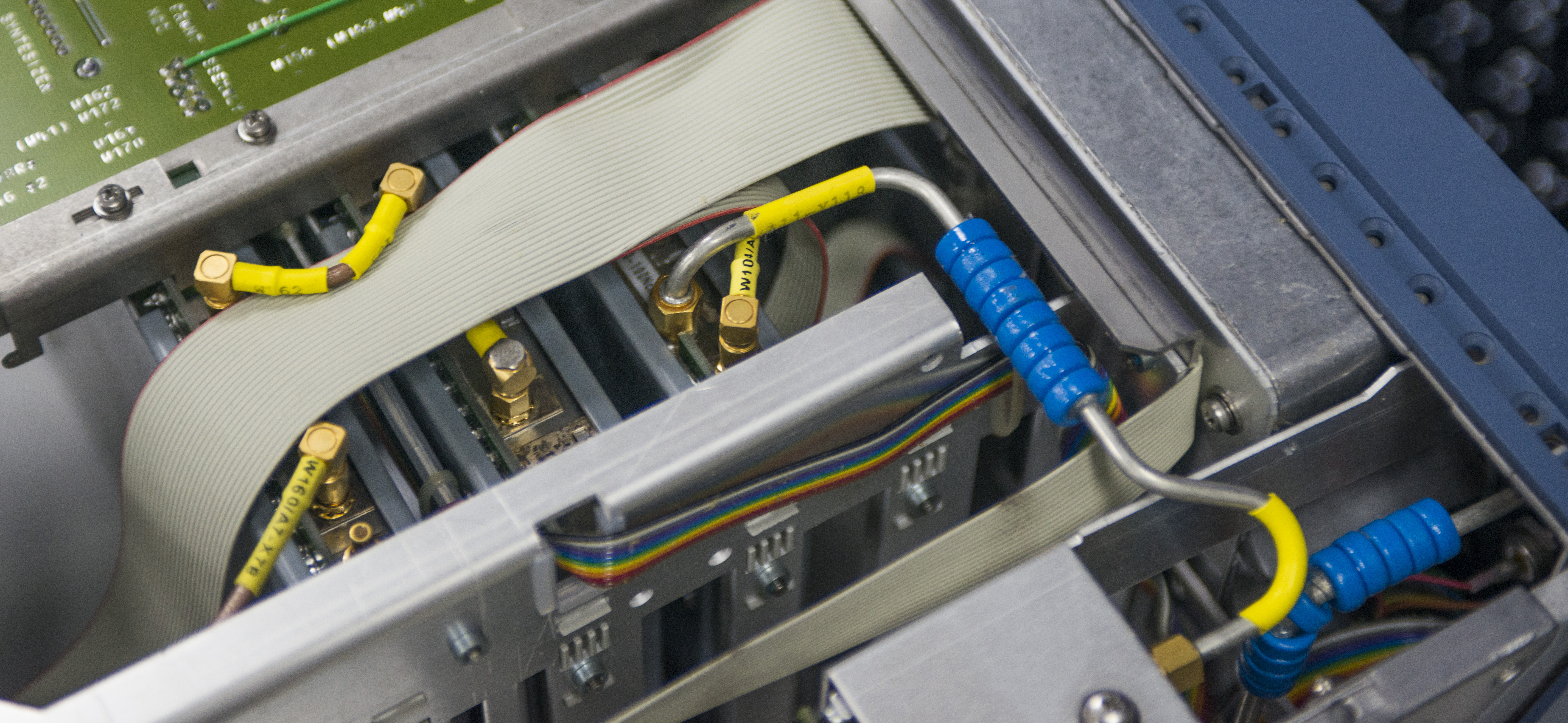
Output unit is 3GHz marked. All modules shielded from both sides and have coaxes running in and out.
Main output is routed via rigid coax with SMA ports.
Output attenuator. It clicks a lot when changing output in big steps :)
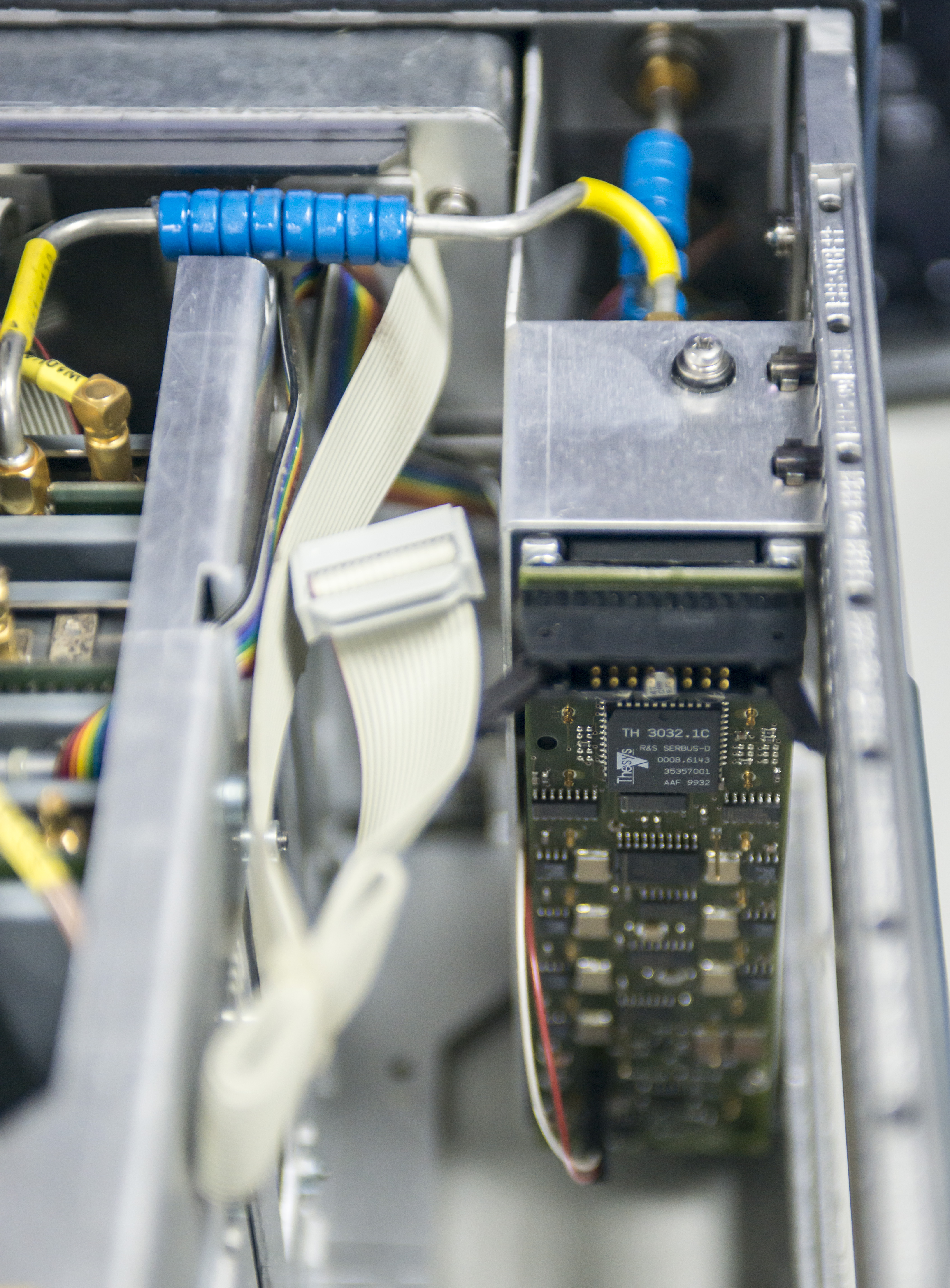
More coax stuff..

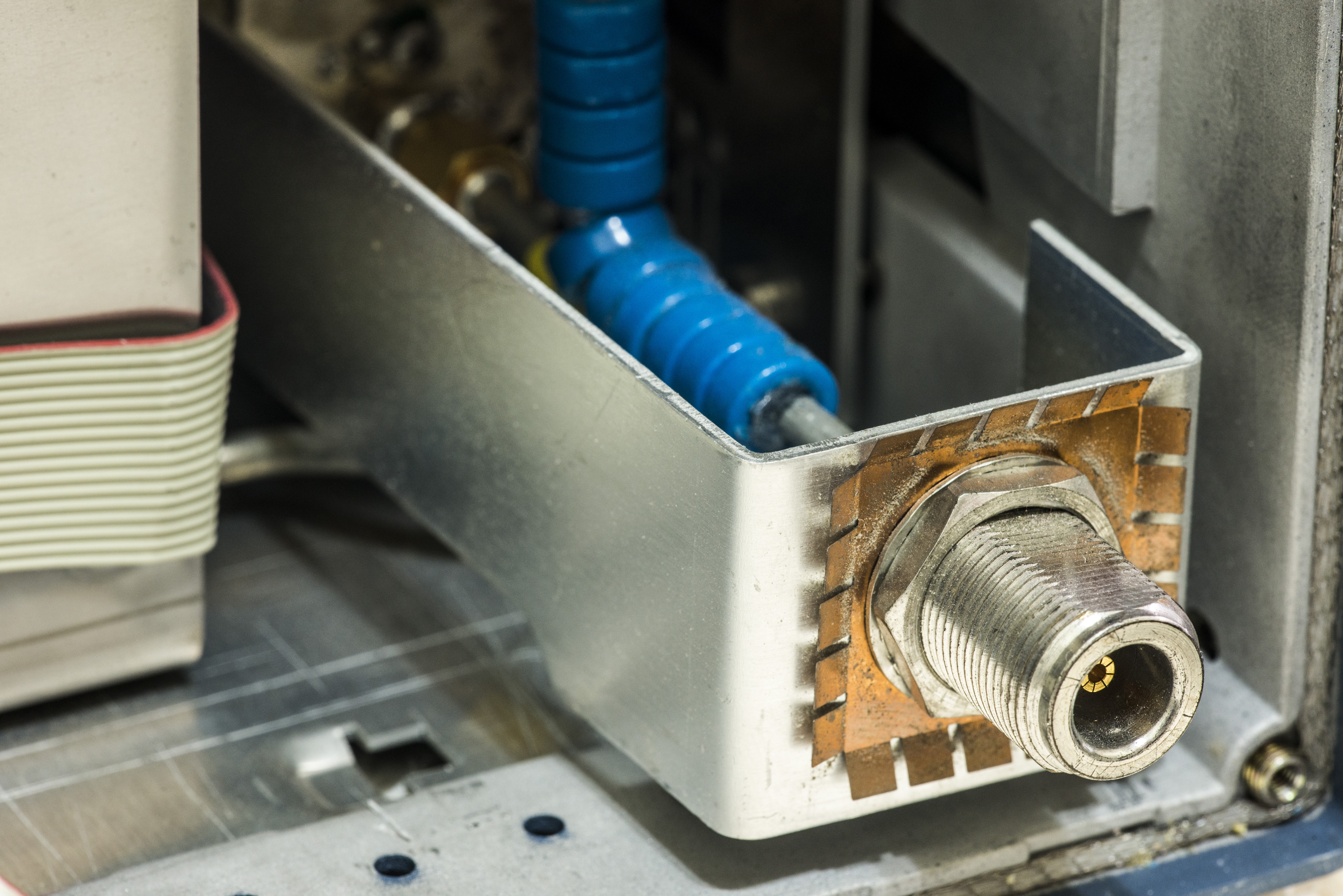
And main output, totally separate from front panel body/assembly.
It’s type N 50 ohm female type.
But our suspect is not in high-frequency area/boards. Where is usually battery located? In digital processor area, near SRAM. And where is processor board?
It’s not here, it’s on front panel module. So I will not touch any of that high frequency boards and go right after front panel..
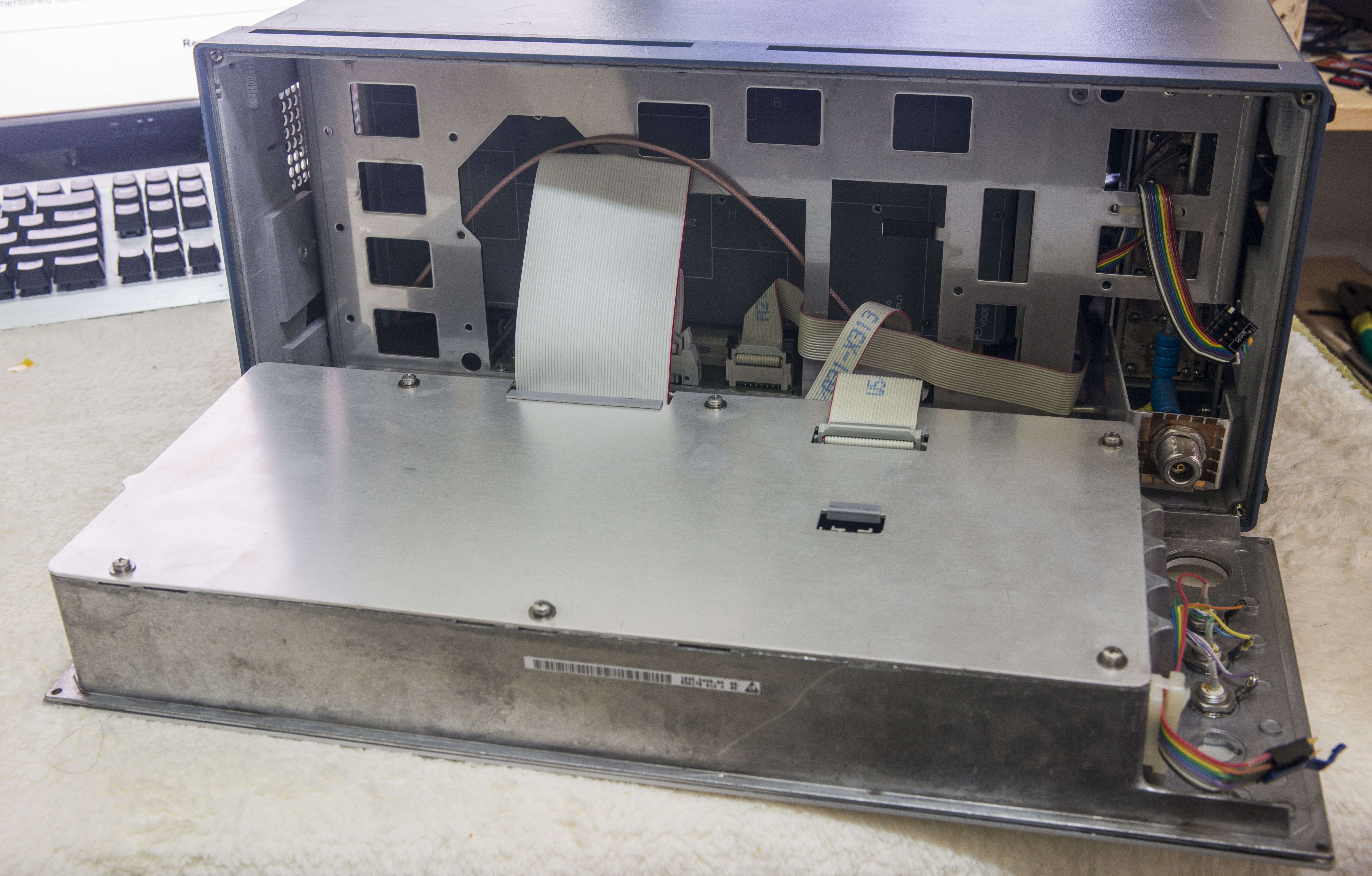
Uncrew 4 corners and here we have, solid metal shielded block with front panel, screen and digital board. Really easy to service.
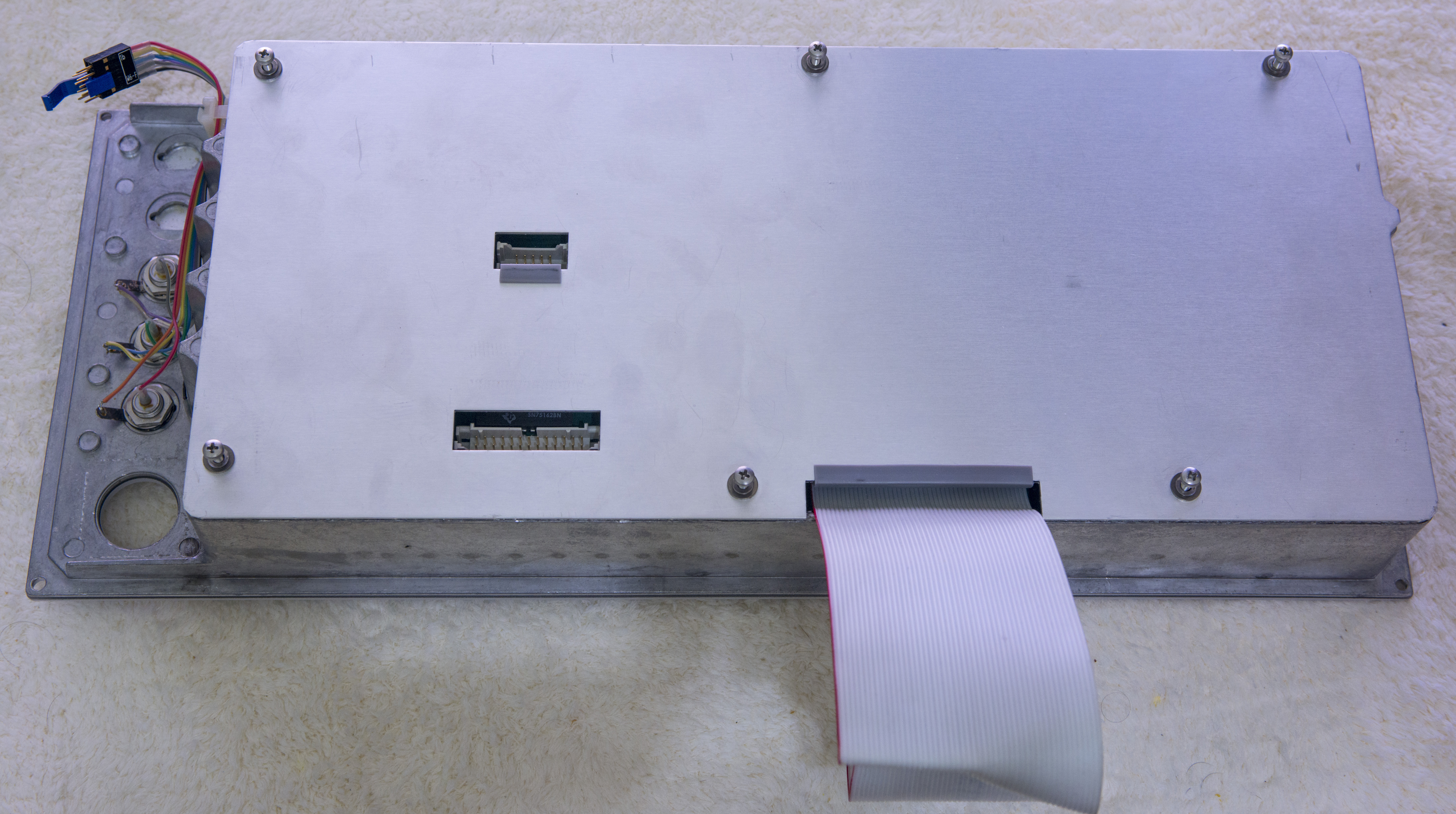
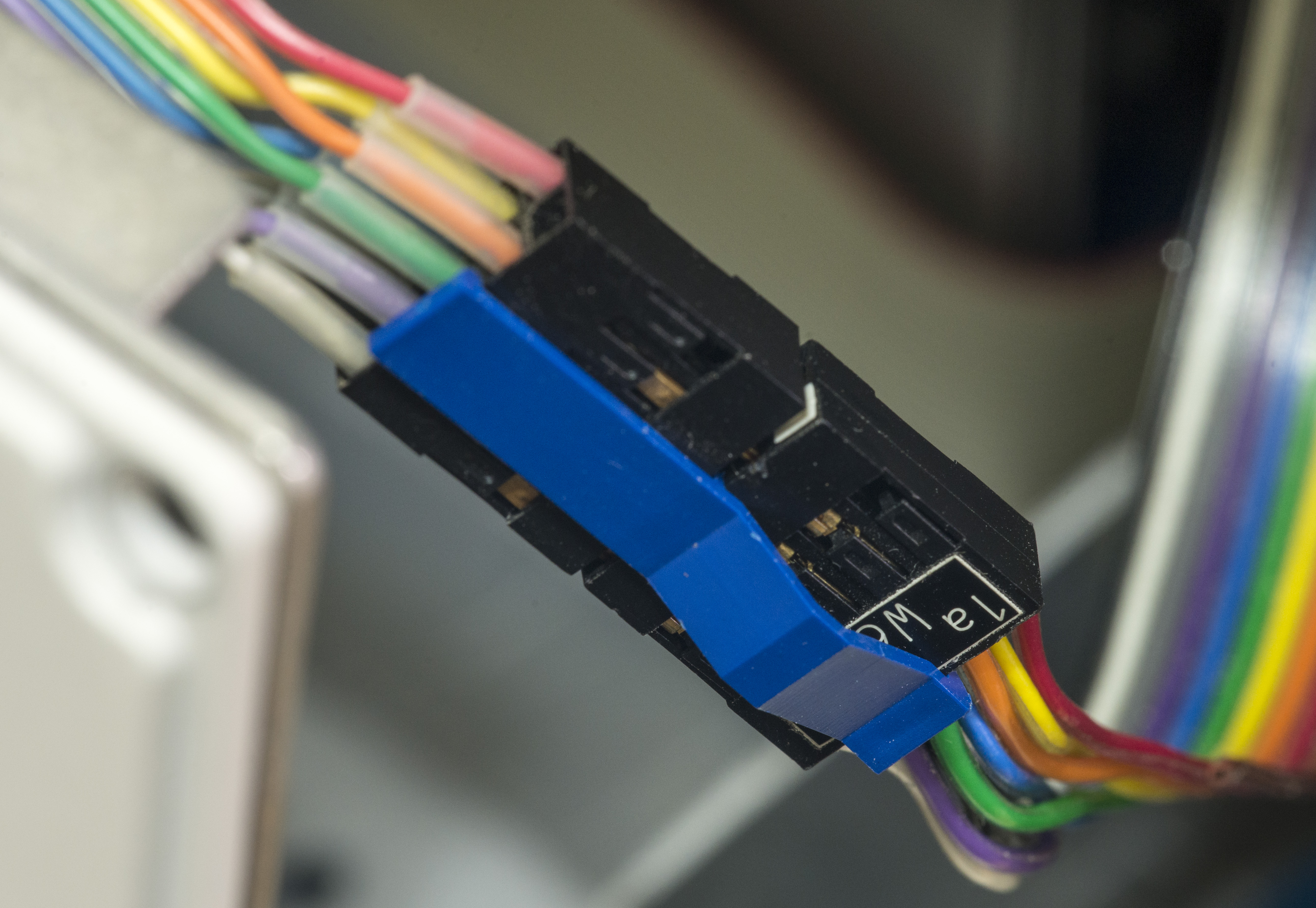
Take a look at attention to details. Even 2.54mm headers have special plastic locks to secure connection.
Or rubber pads on ribbon cables entry holes on shield to prevent cutting cable by metal edge.
Remove back shield:
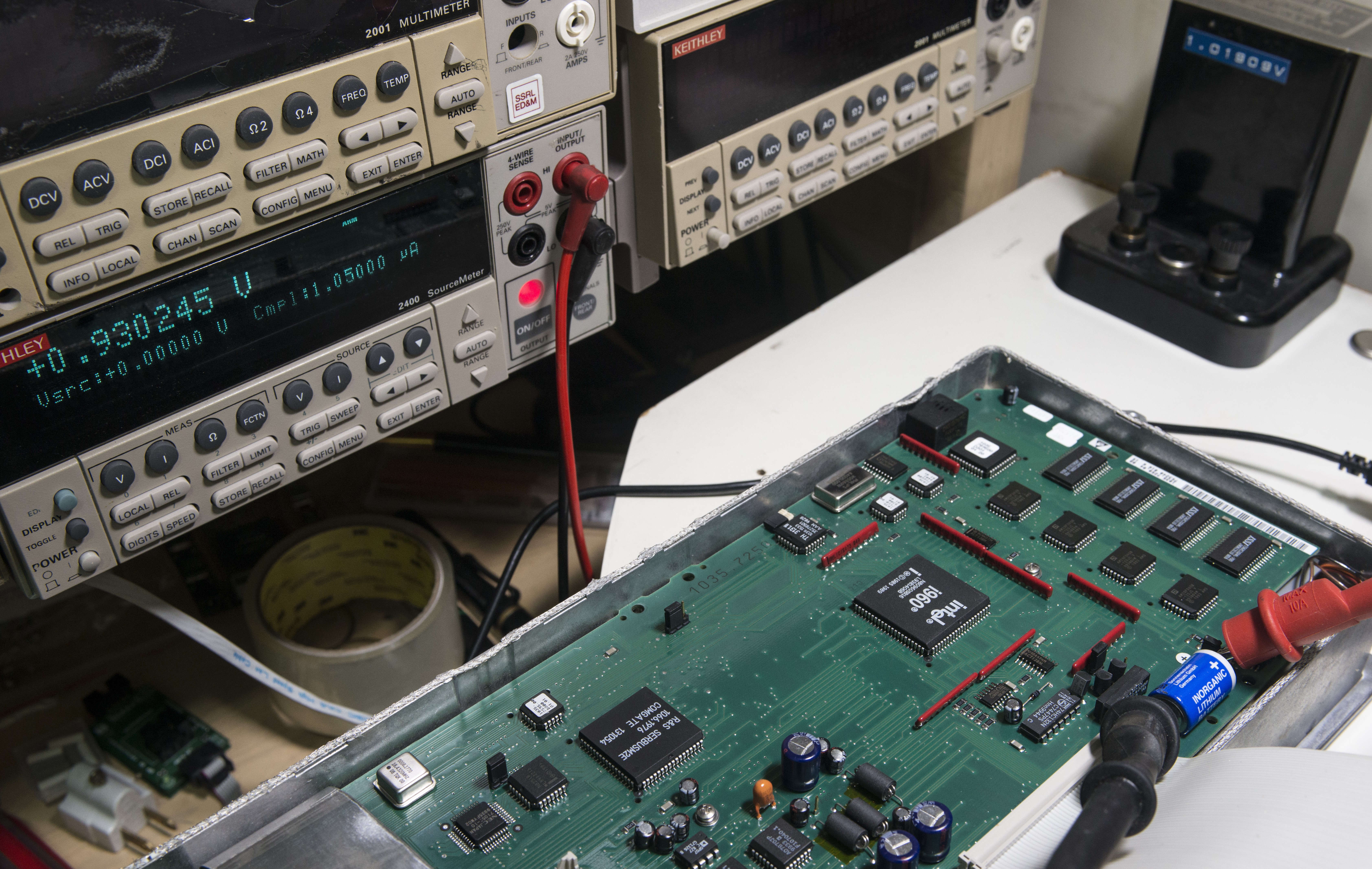
Delithium crystal detected, blue thingy bottom right near CPU.
Which is Intel i960. Not a common guest in test equipment.
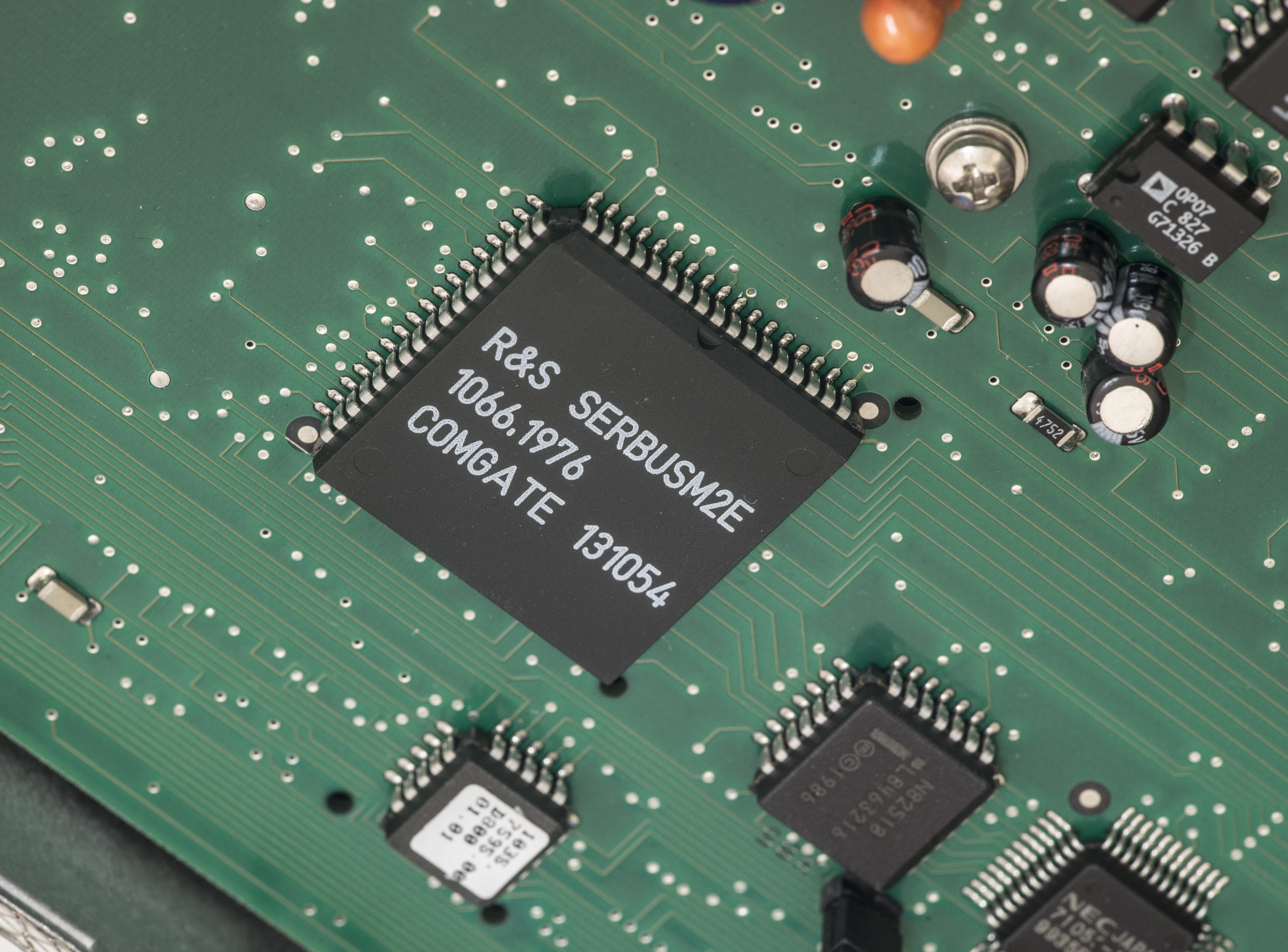
Some more chips with funny names, like comgate, orbit…
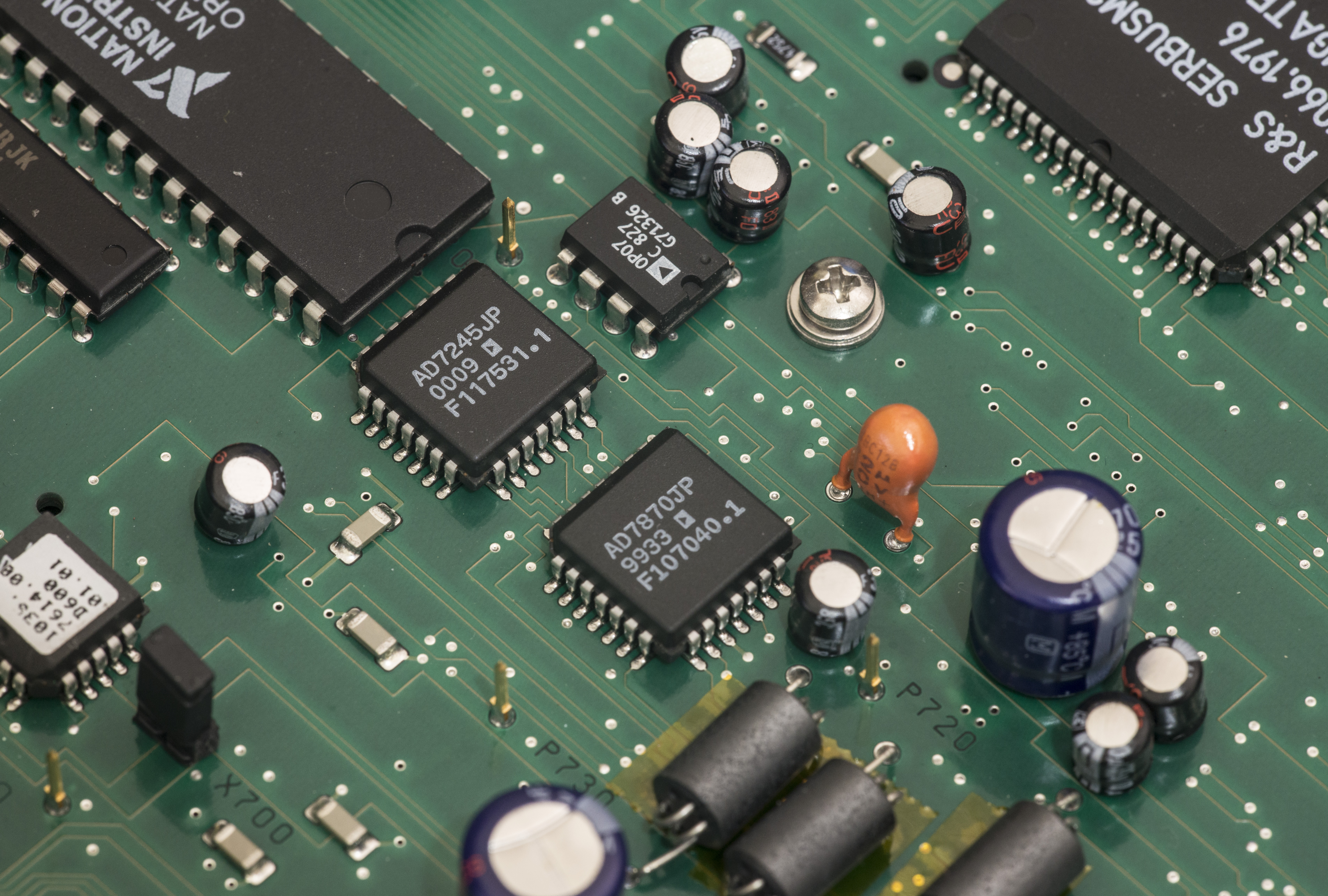
And some ADI stuff
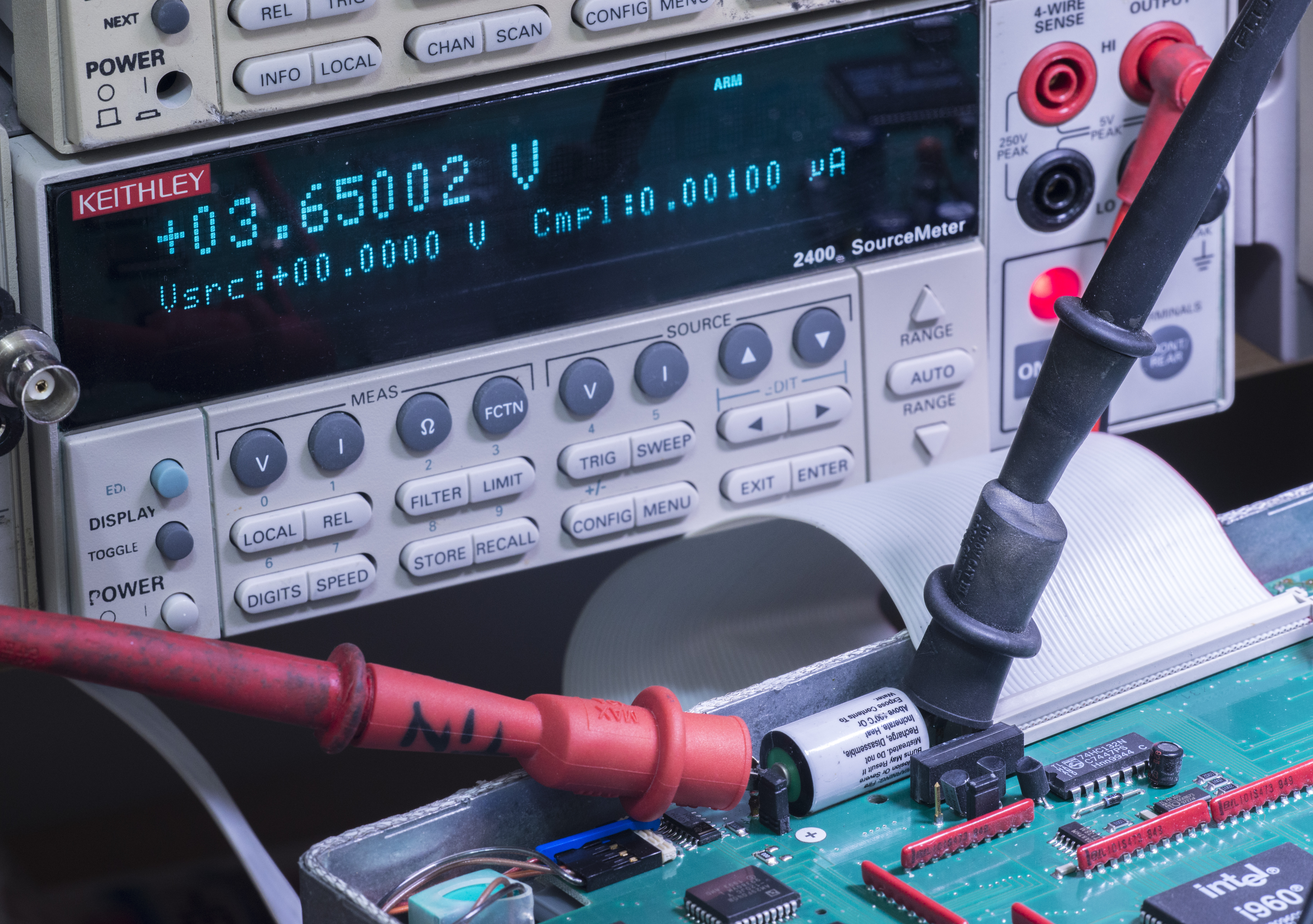
Ok, let’s check battery voltage…
0.93V, no good!
Desolder batt of the board.
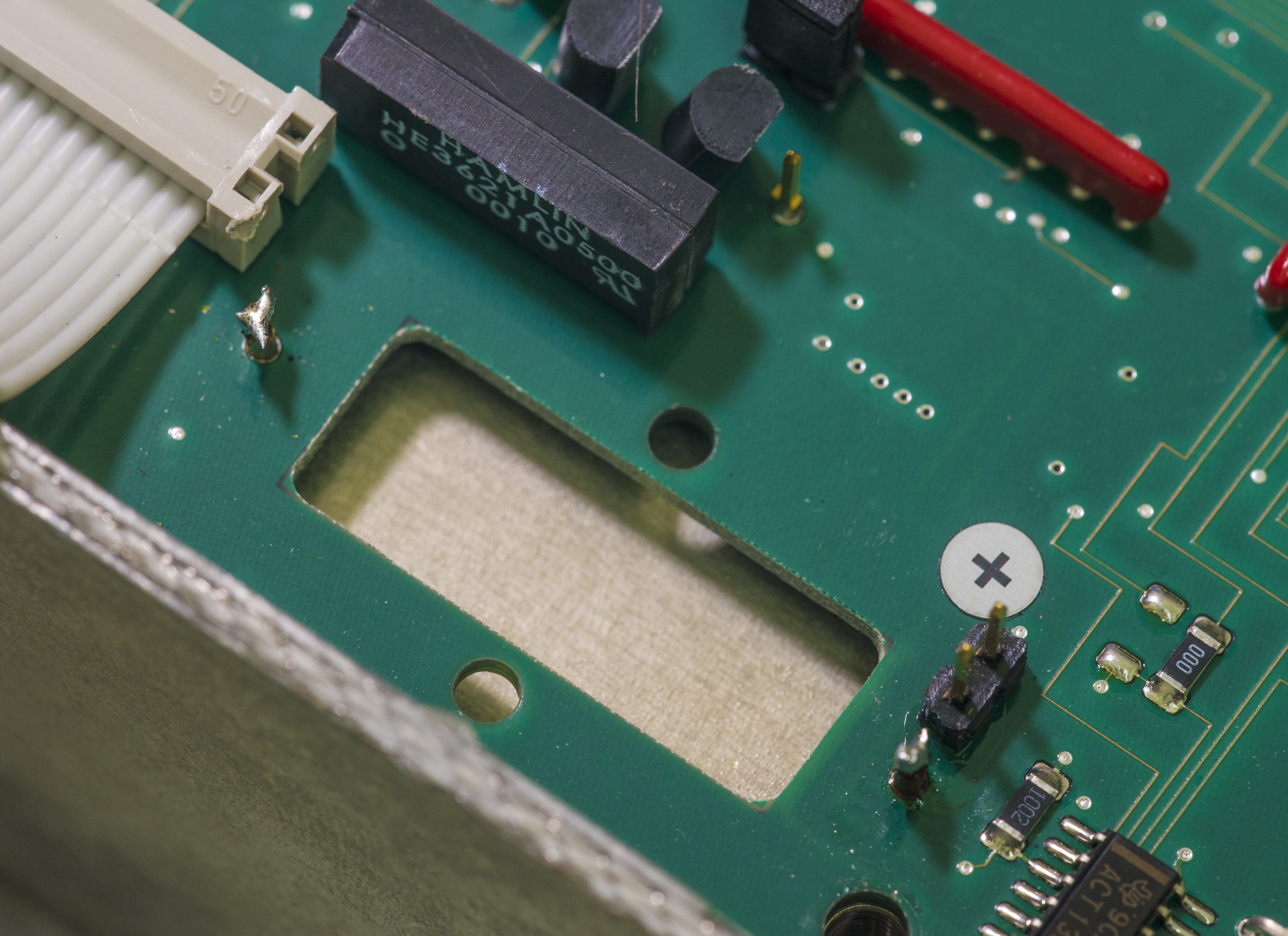
Have nice cutout and standoffs for easy servicing. Jumper nearby connects positive terminal to board. Well thought!
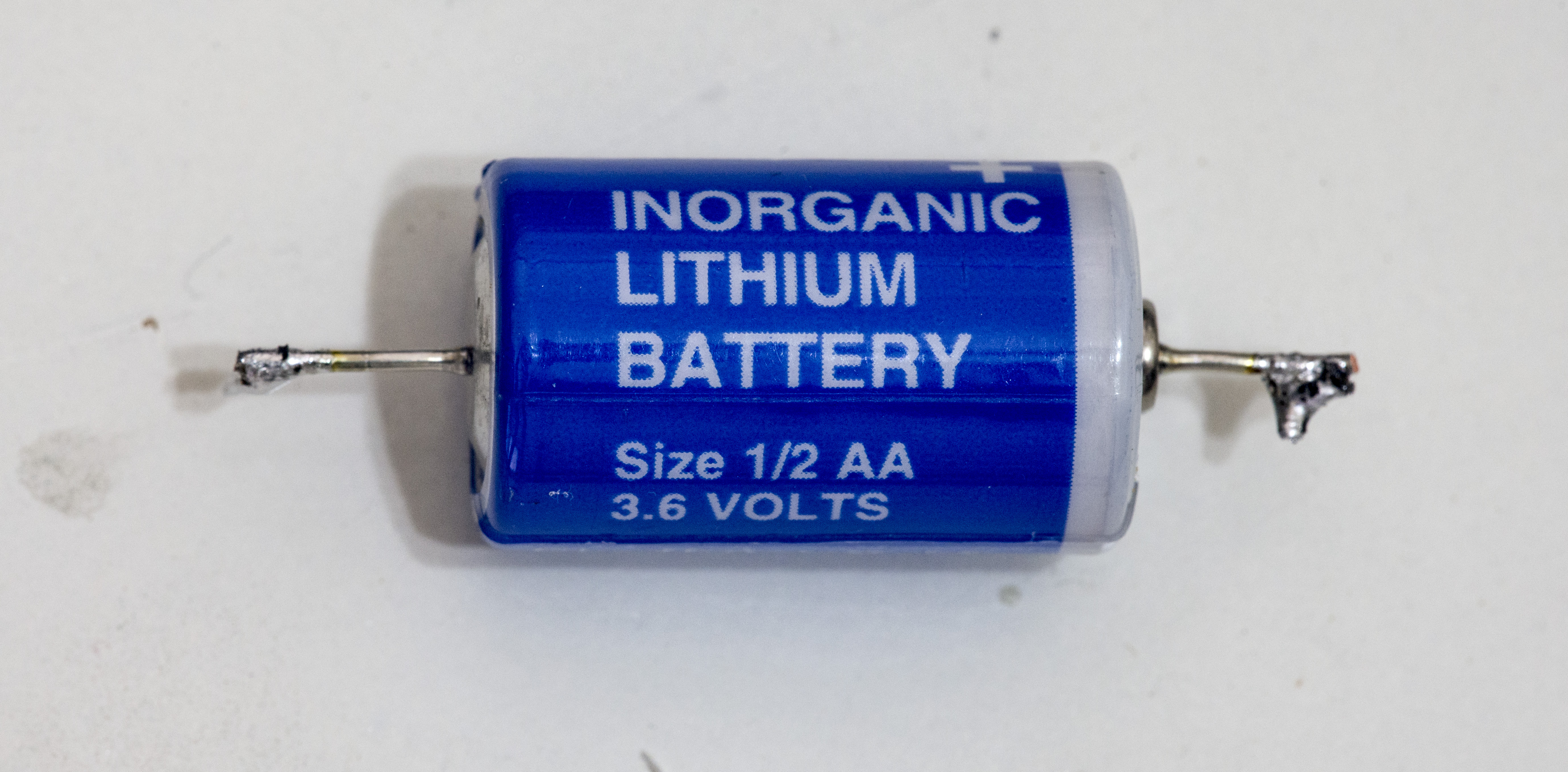
Battery itself (this photo is actually of original battery which I replaced when just got a unit):
Solder new battery in and voltage check:
Now assemble everything back and check.
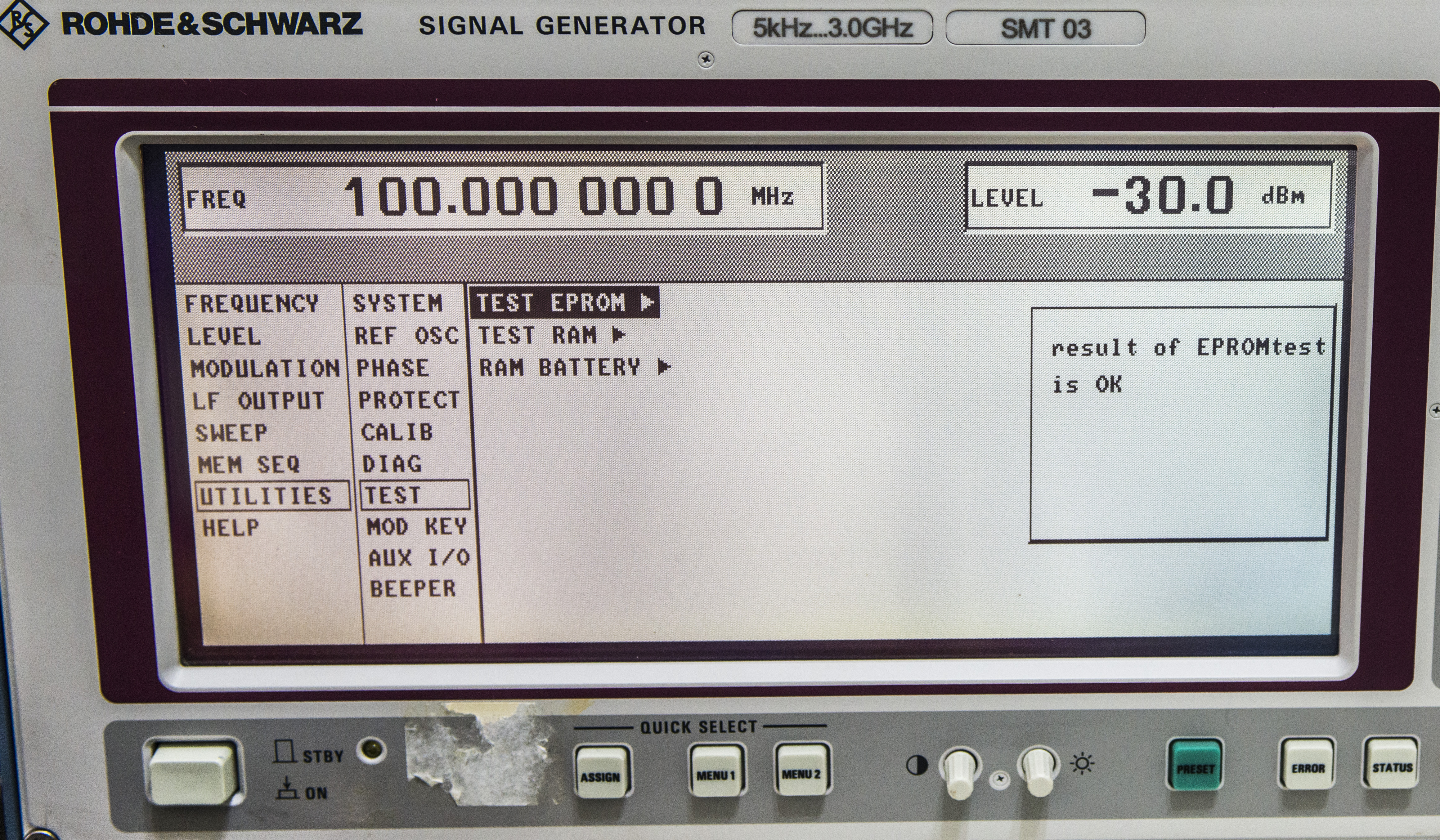
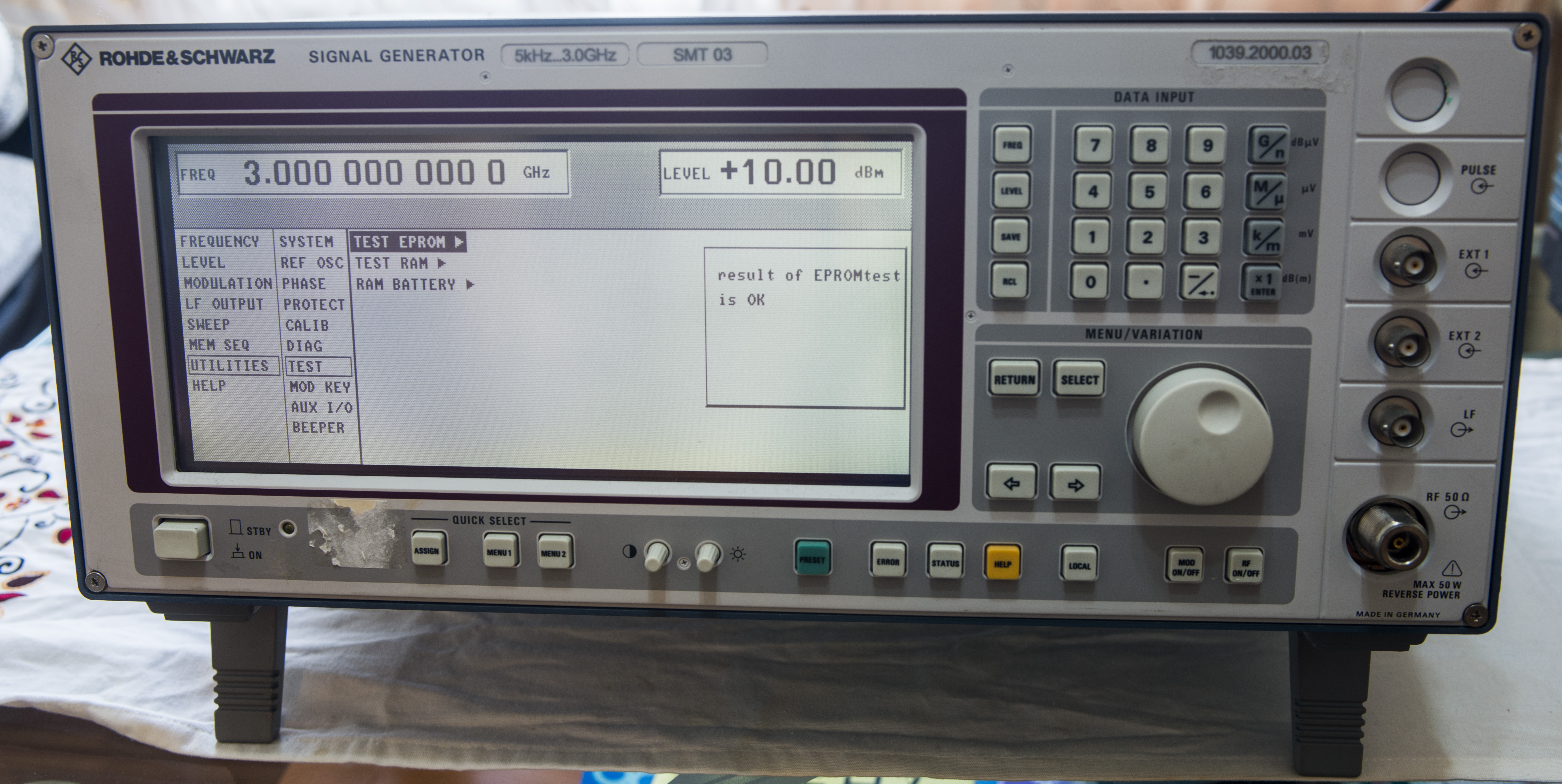
Unit boots fine, run self-diags:

OK!
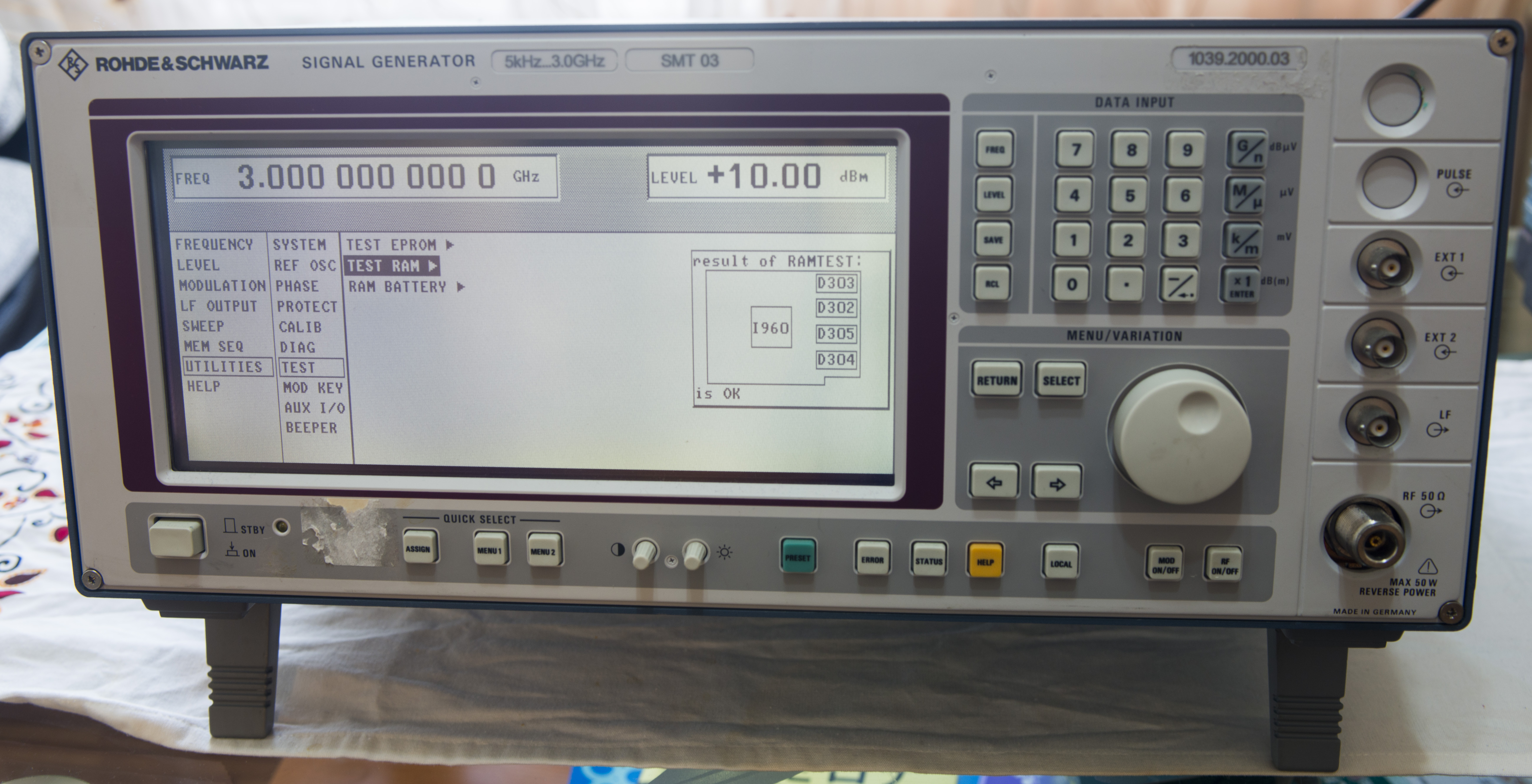
OK!
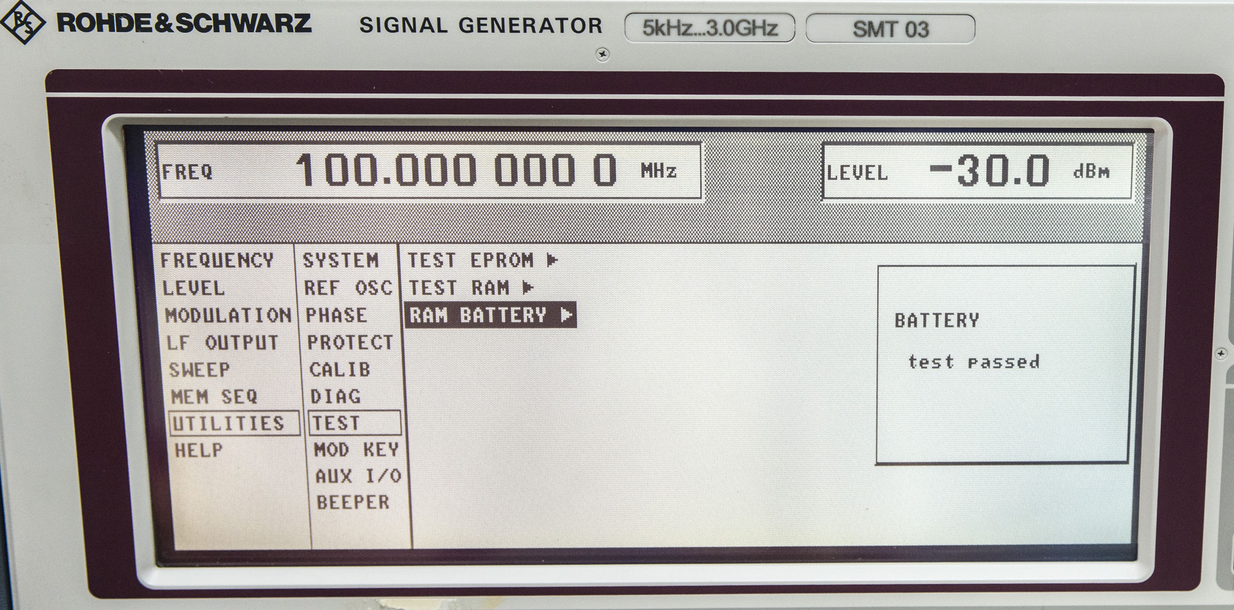
Battery passed and OK now.
All errors and calibration was restored by unprotecting PROT1 LEVEL via entry of password “123456” and running VCO,FM calibration steps. All this is performed by internal operation,
no need external calibrators or connections.
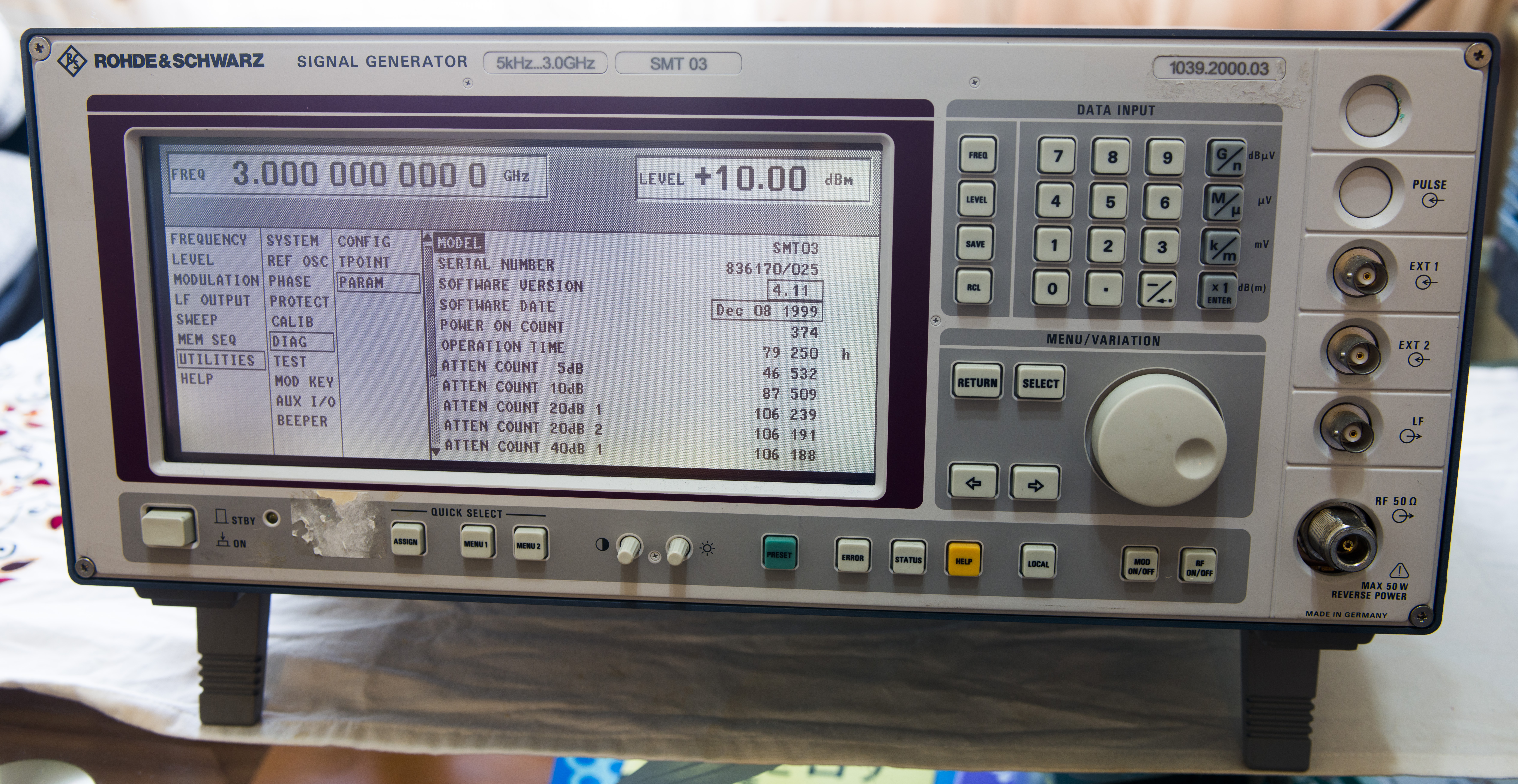
And some information about unit:
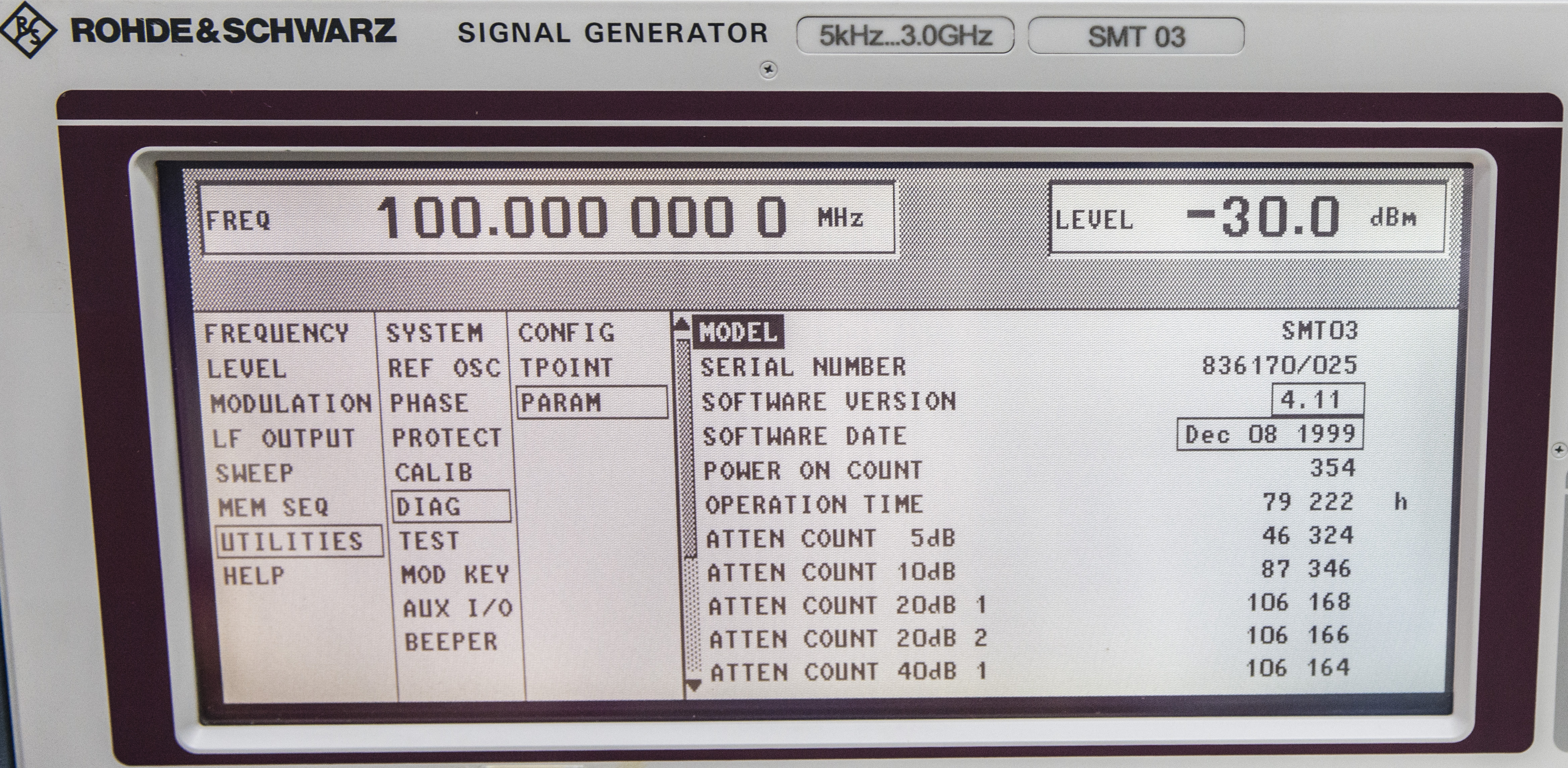
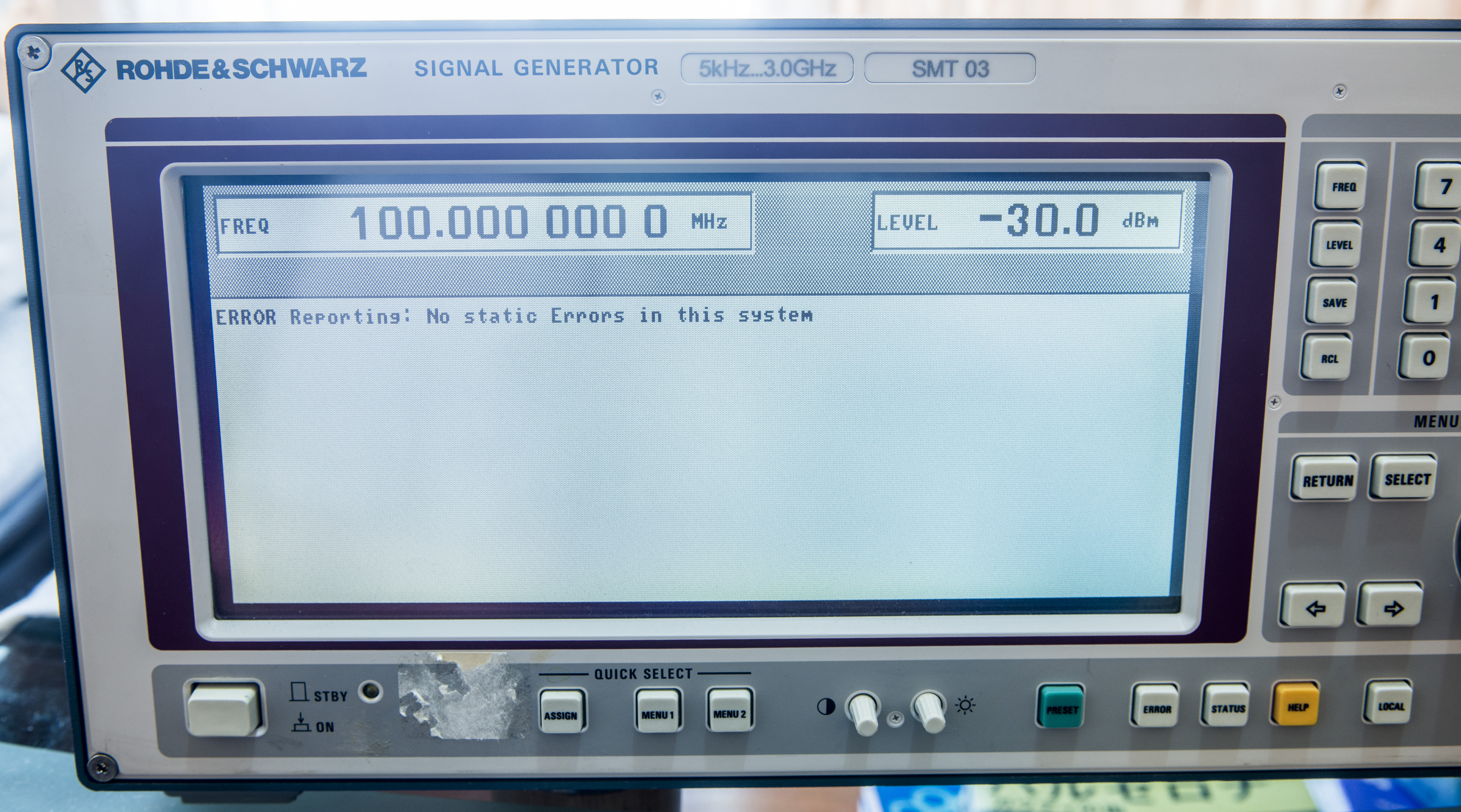
No errors in this system:
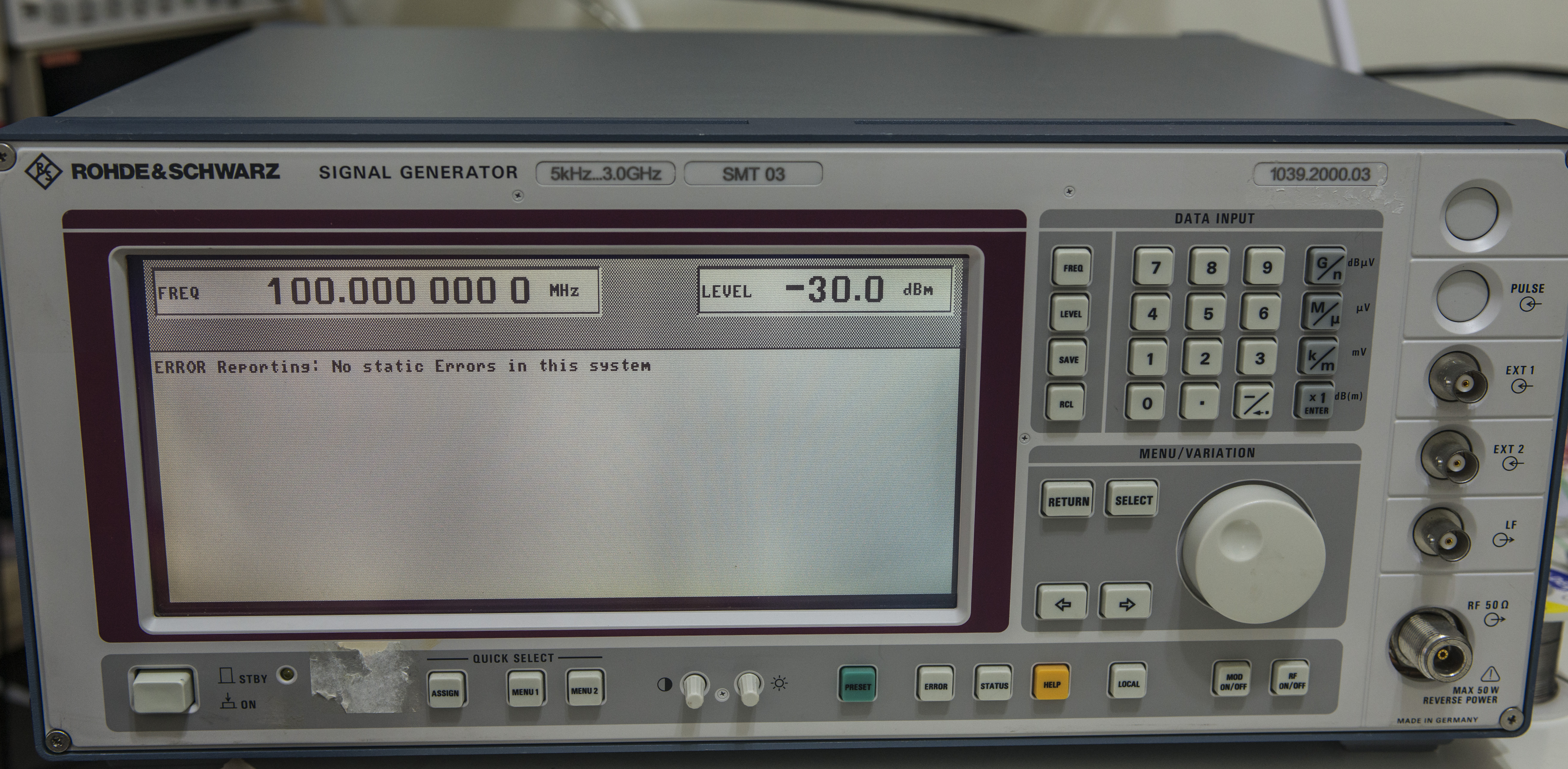
So now unit back in business to full operation
4K UHD resolution for details
Extra photos
Exterior:
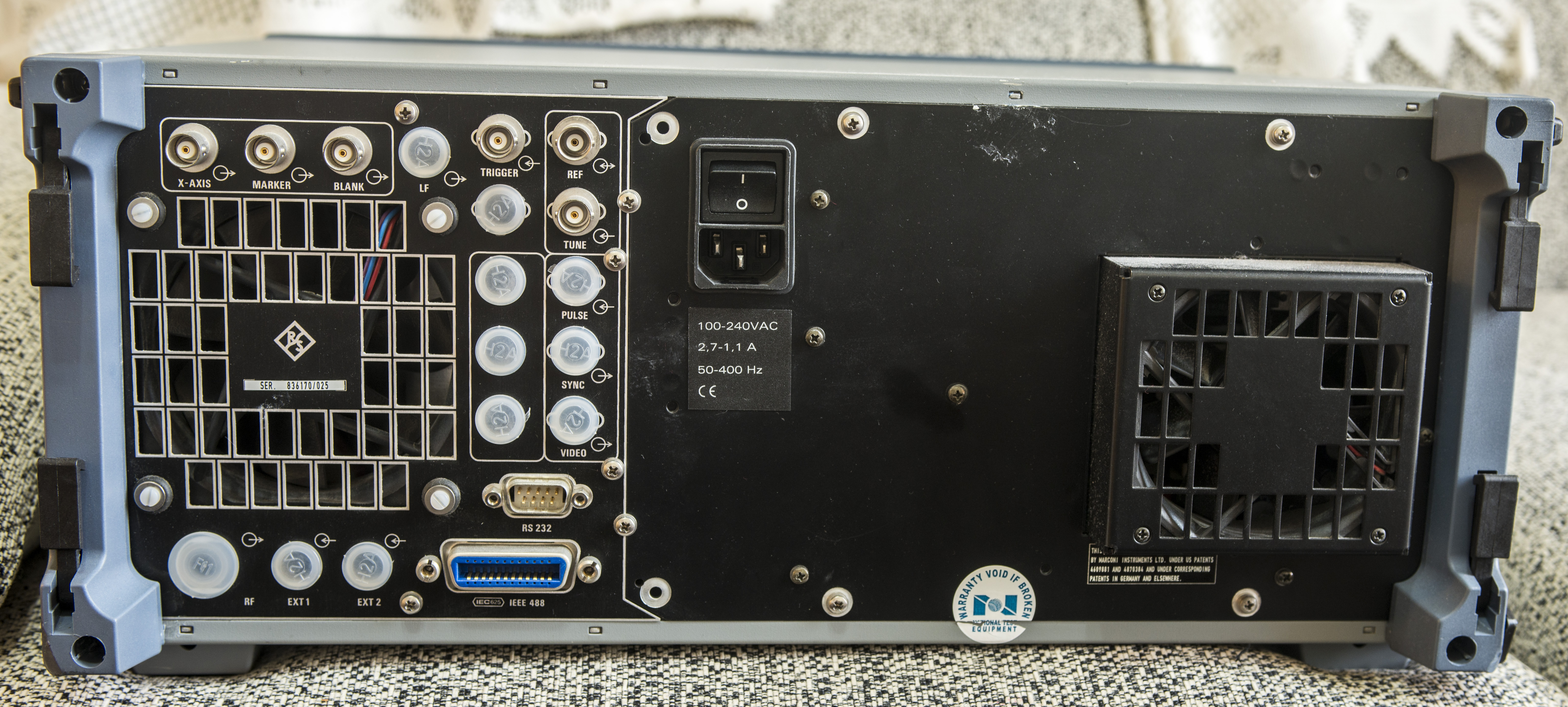
Back side connectors and ports:
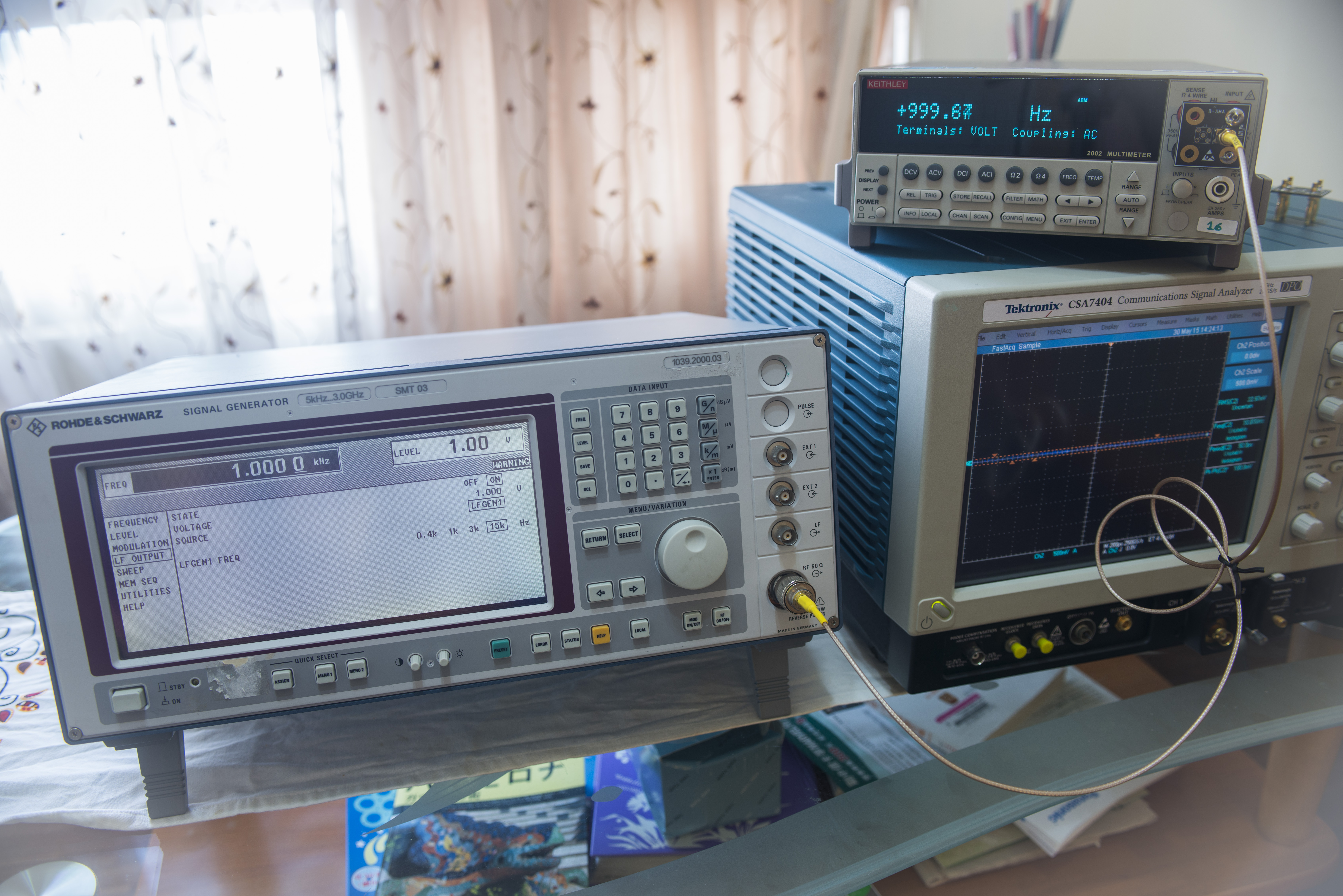
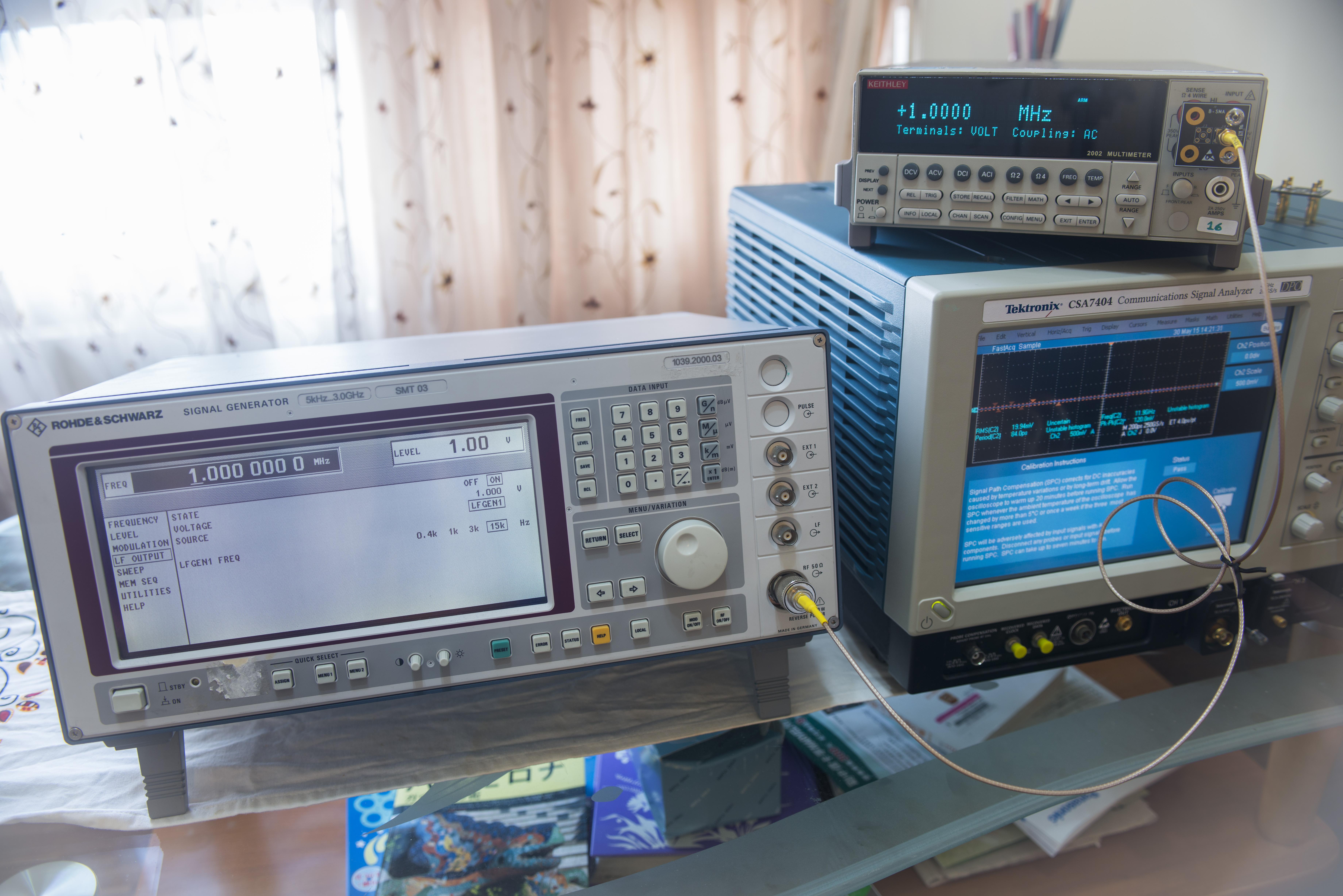
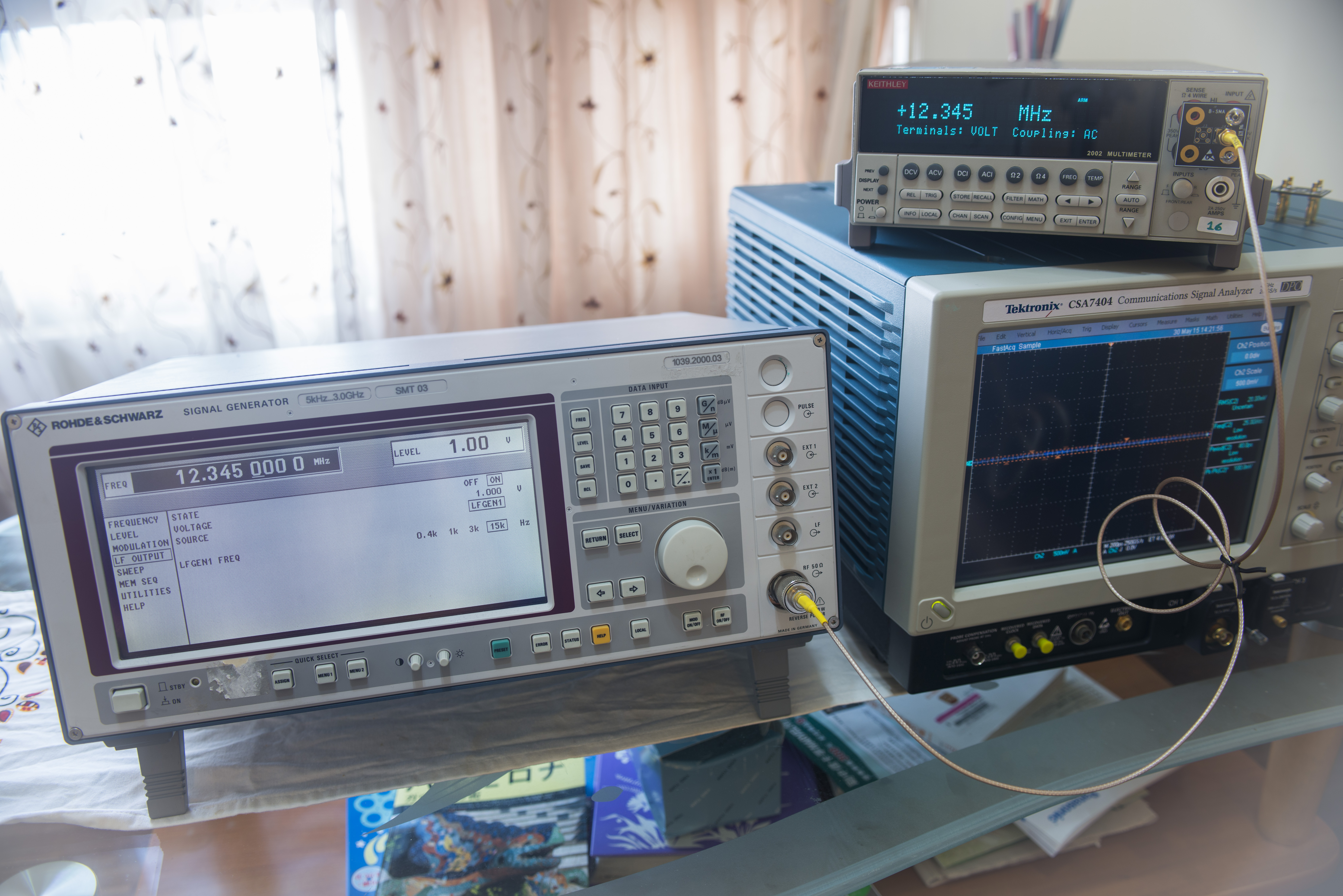
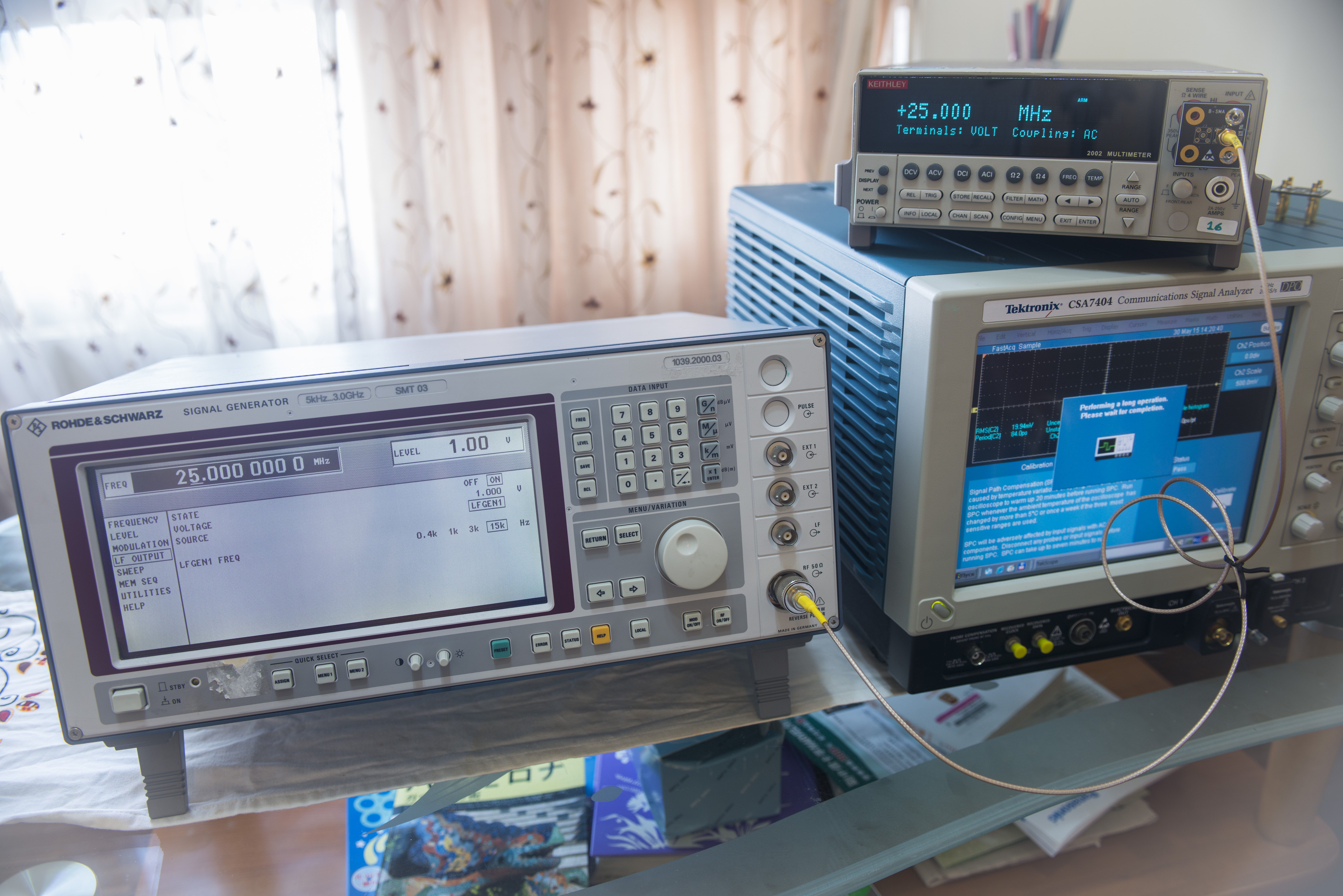
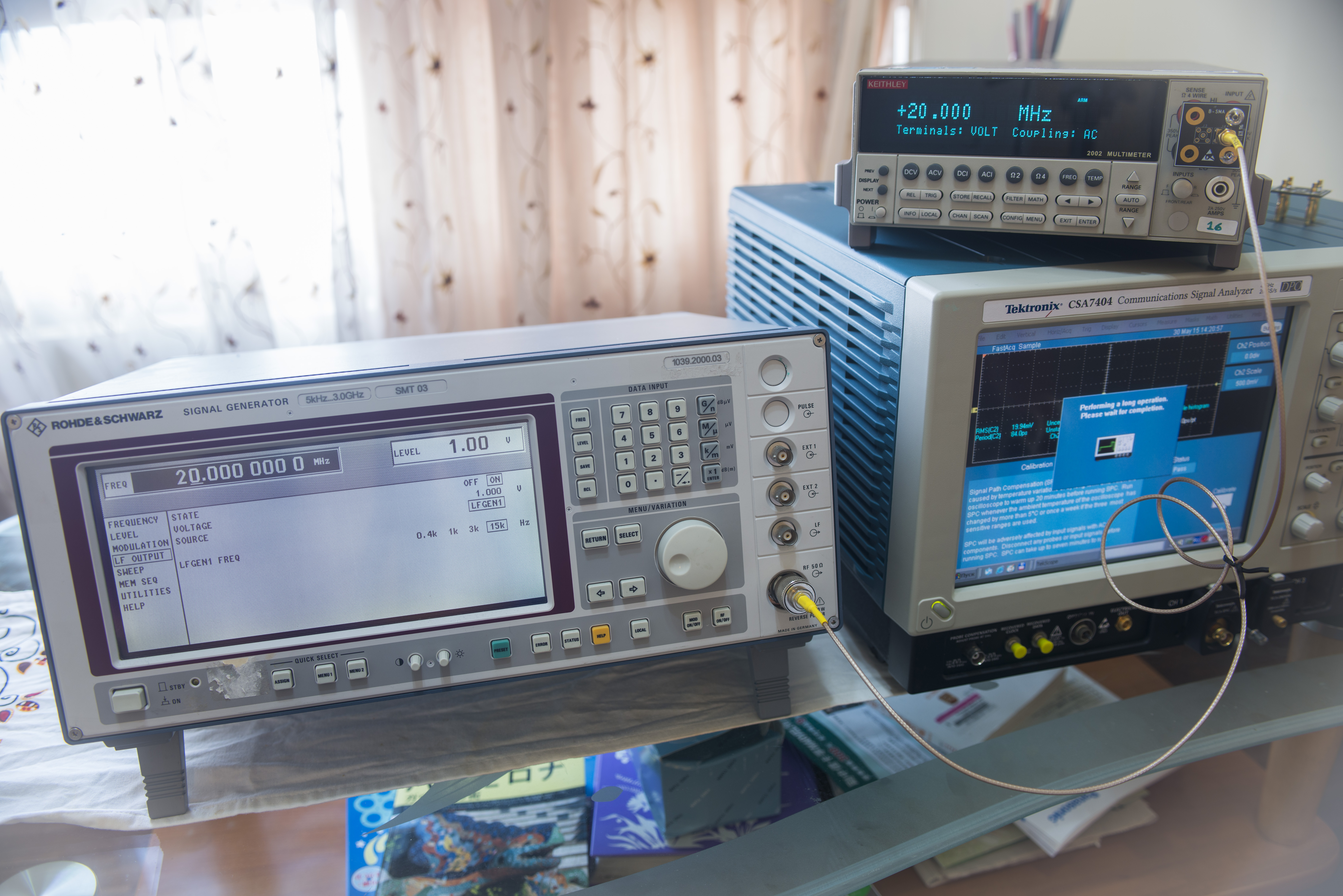
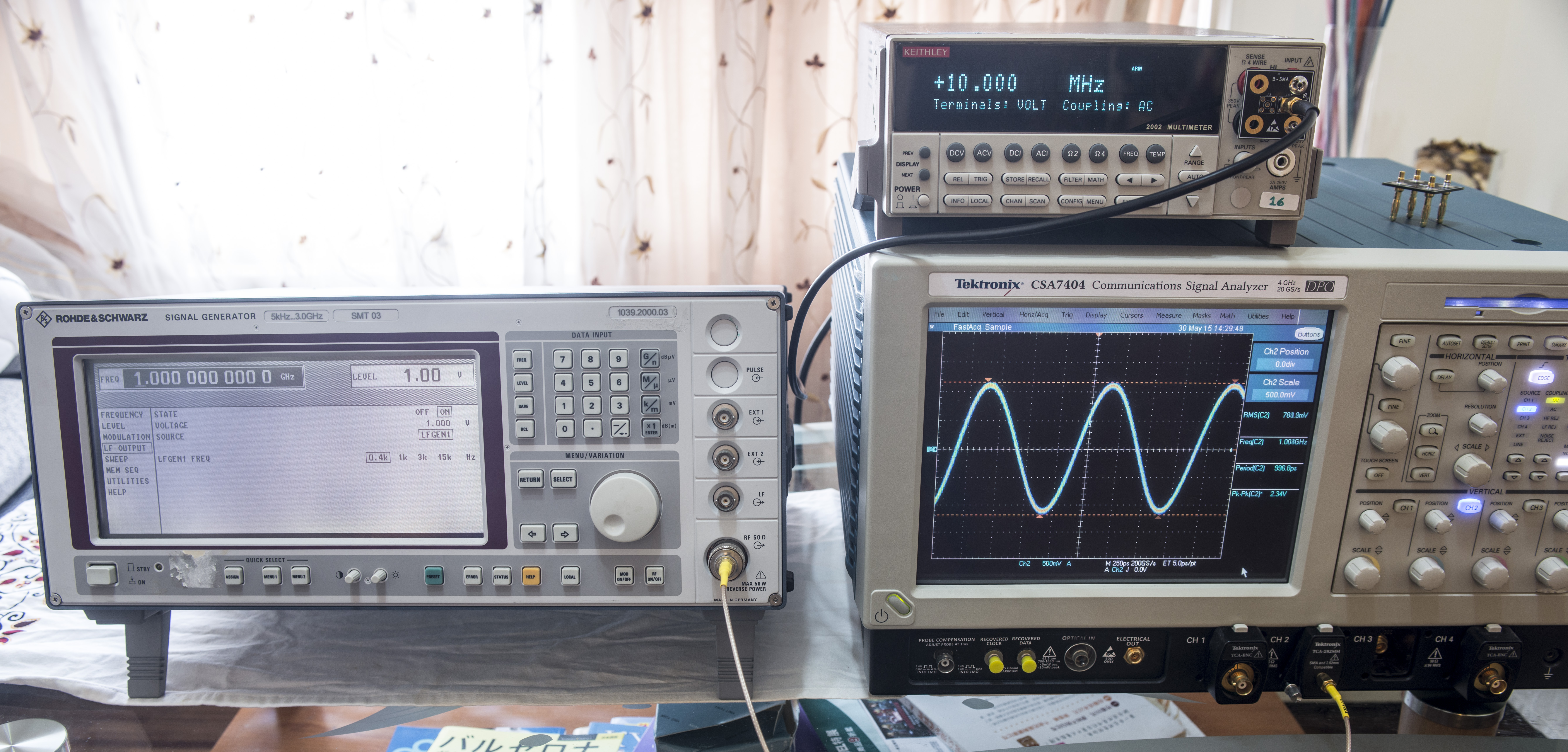
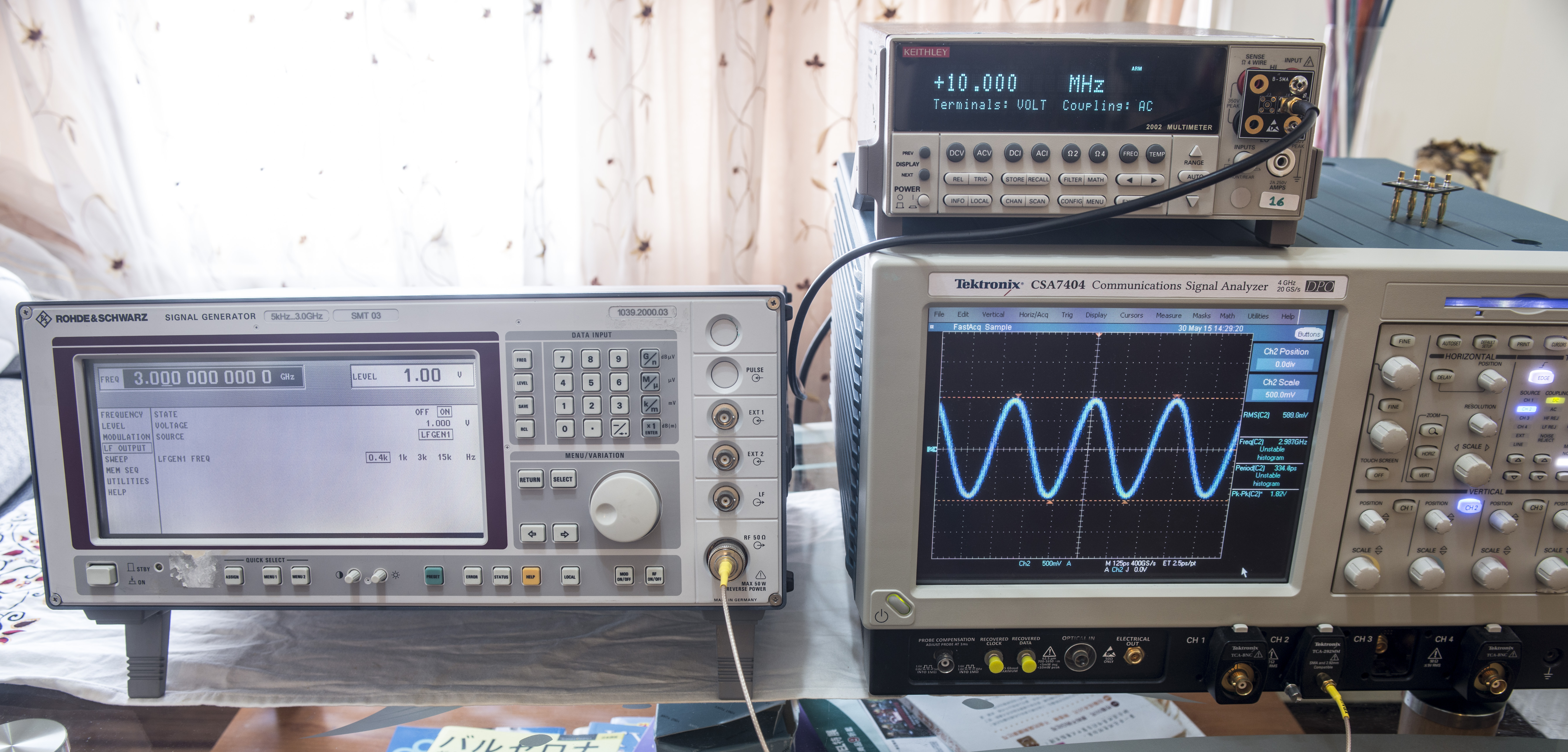
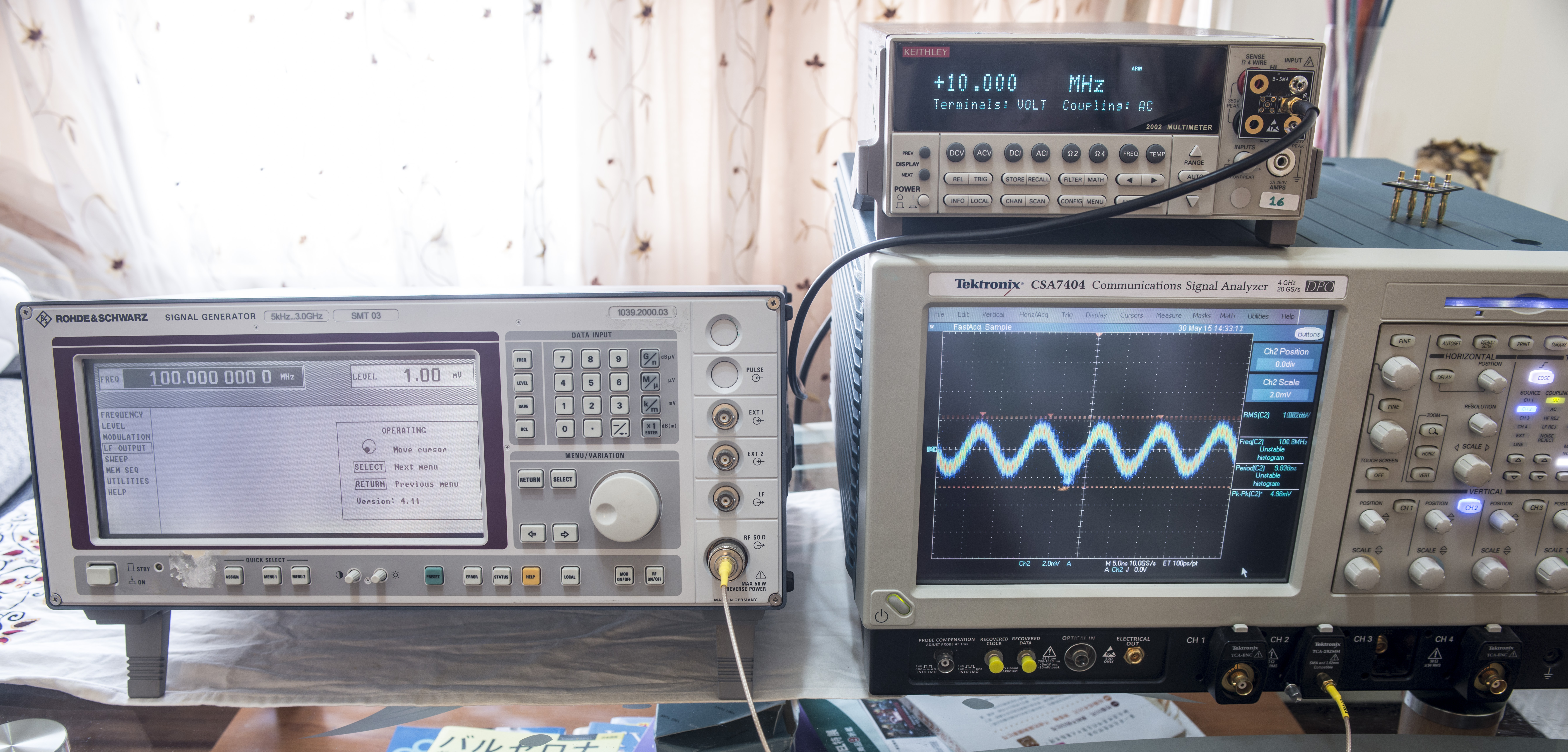
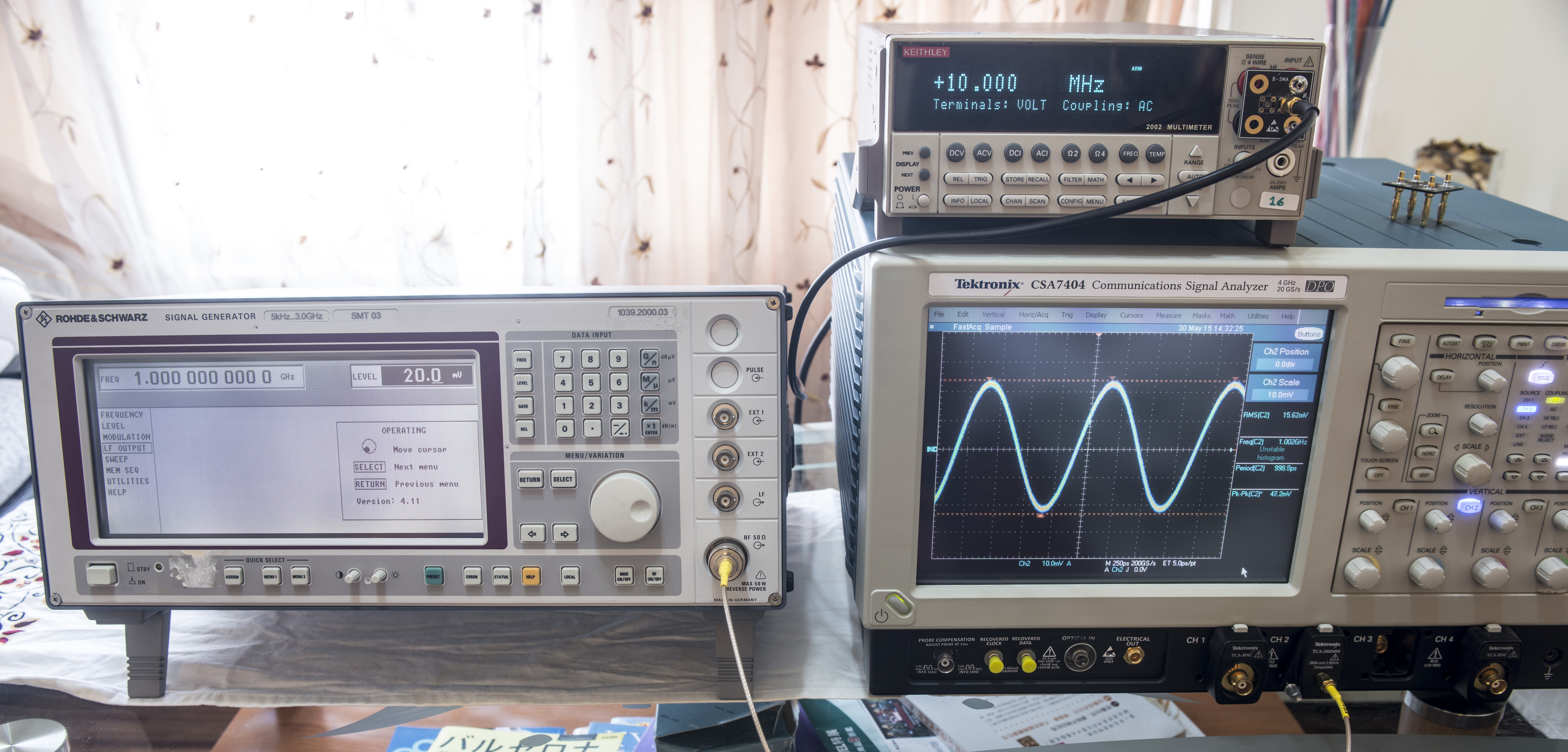
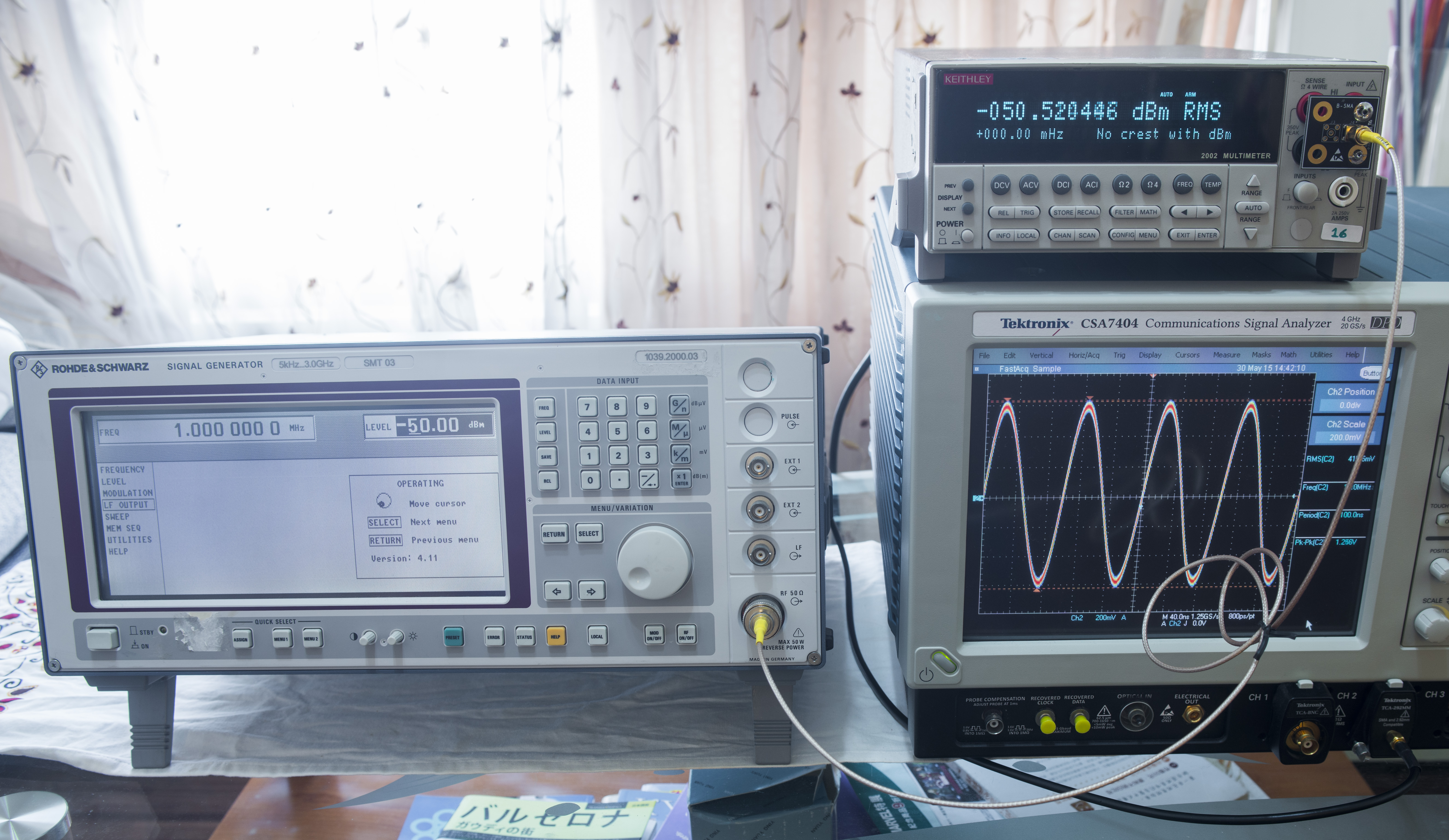
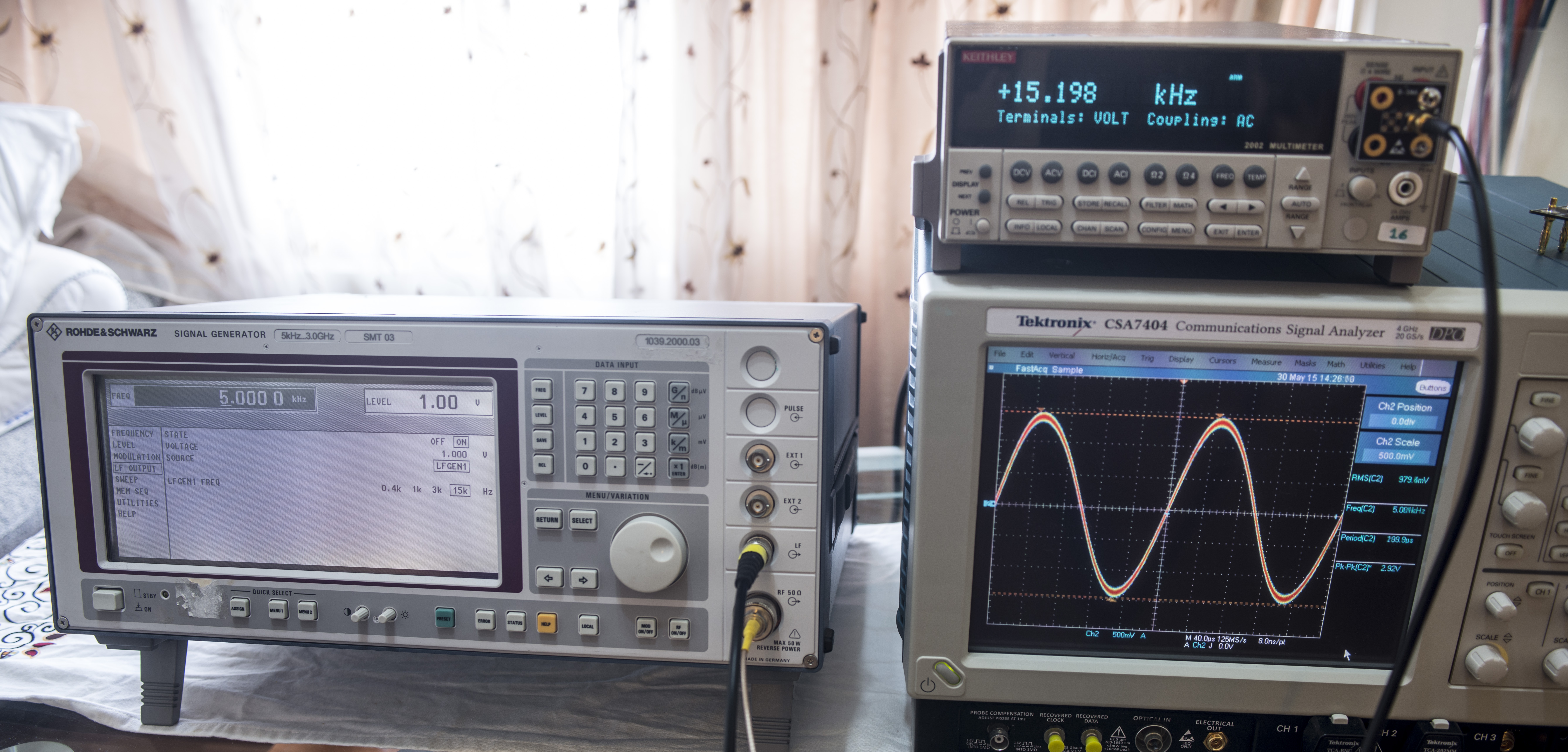
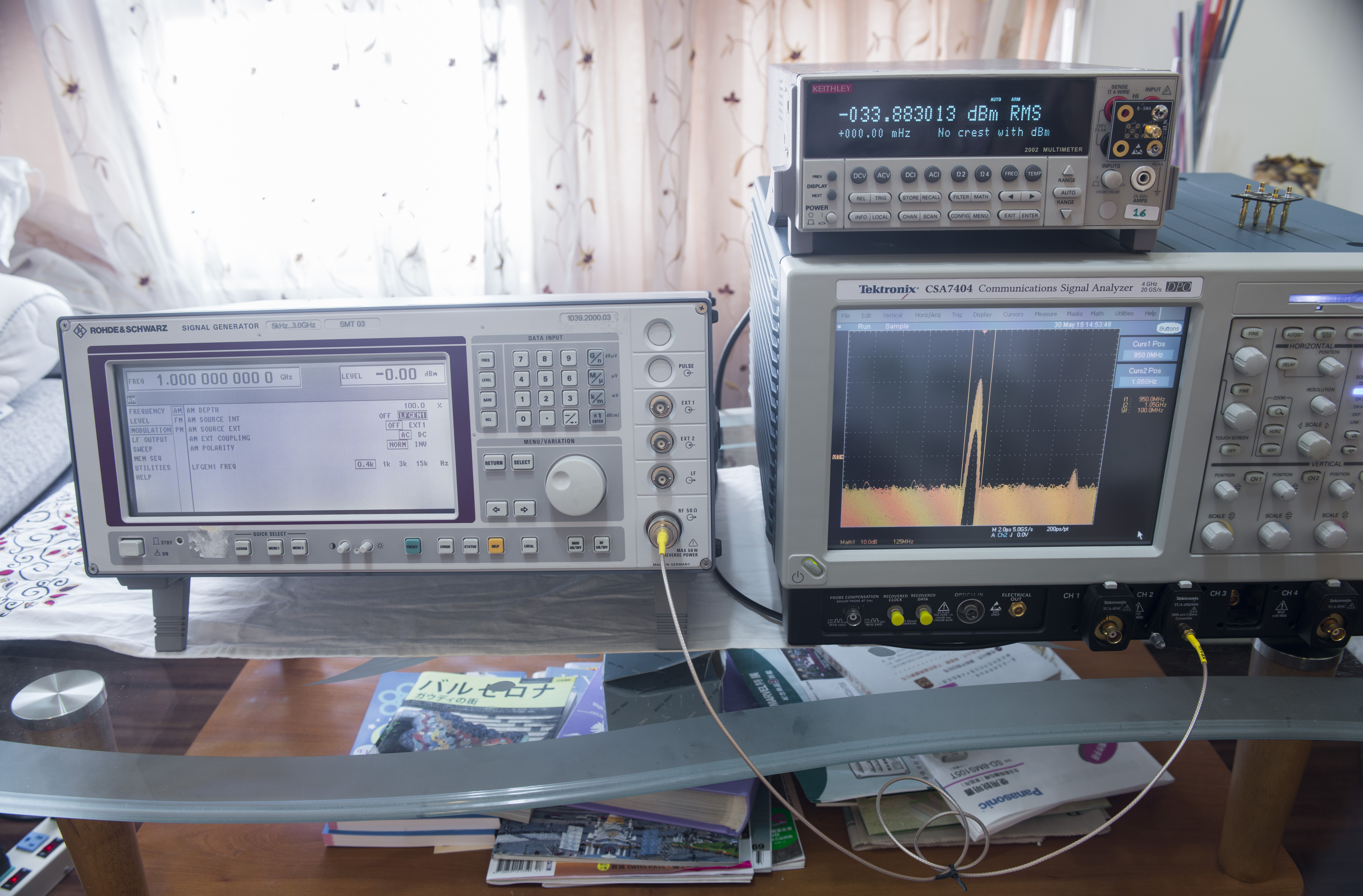
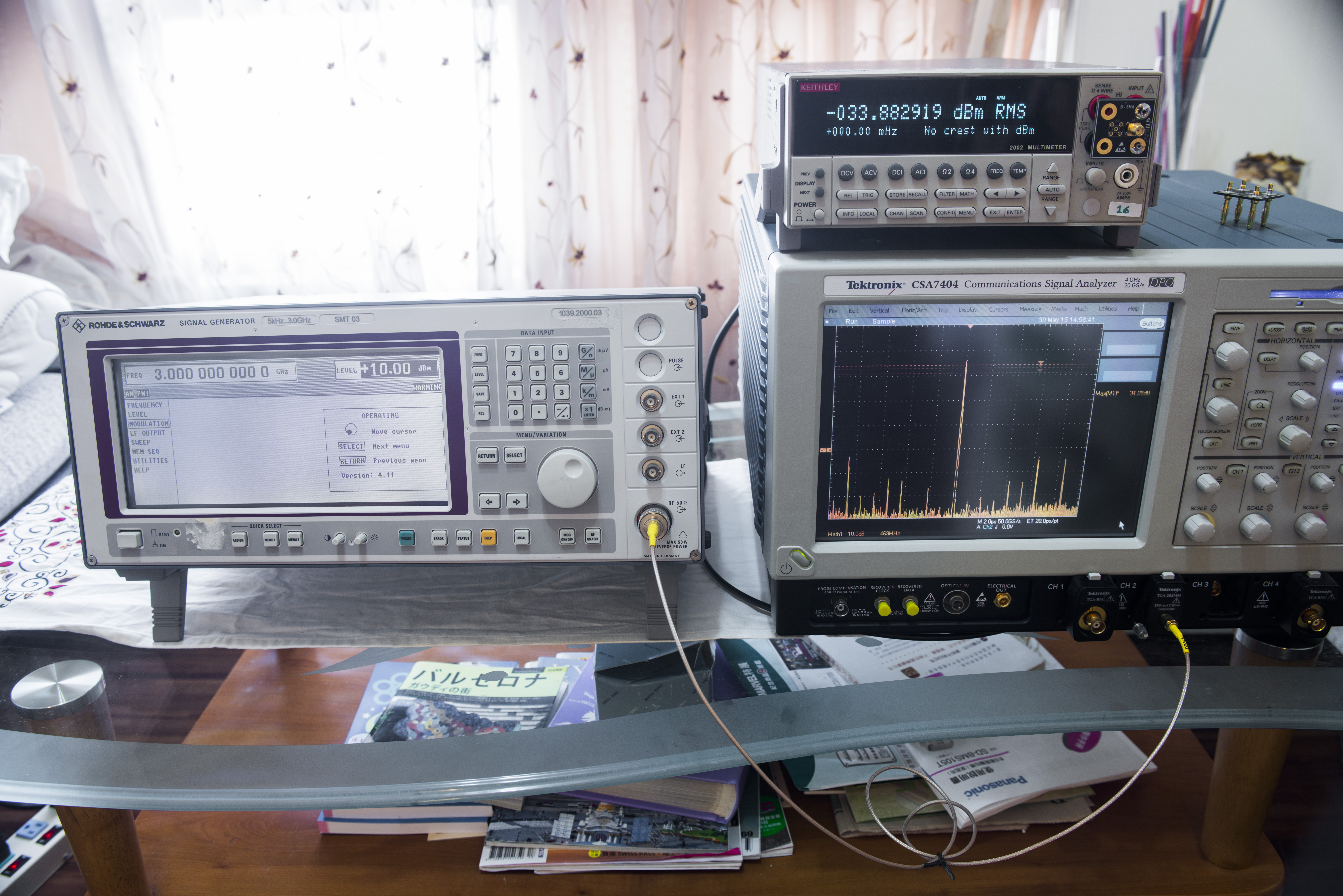
Test setup:
- Tektronix CSA7404 4GHz oscilloscope with TCA-BNC and N-to-BNC cables for signal measurements
- Keithley Model 2002 with Banana-SMA adapter and N-to-SMA cable for level and AC measurements.
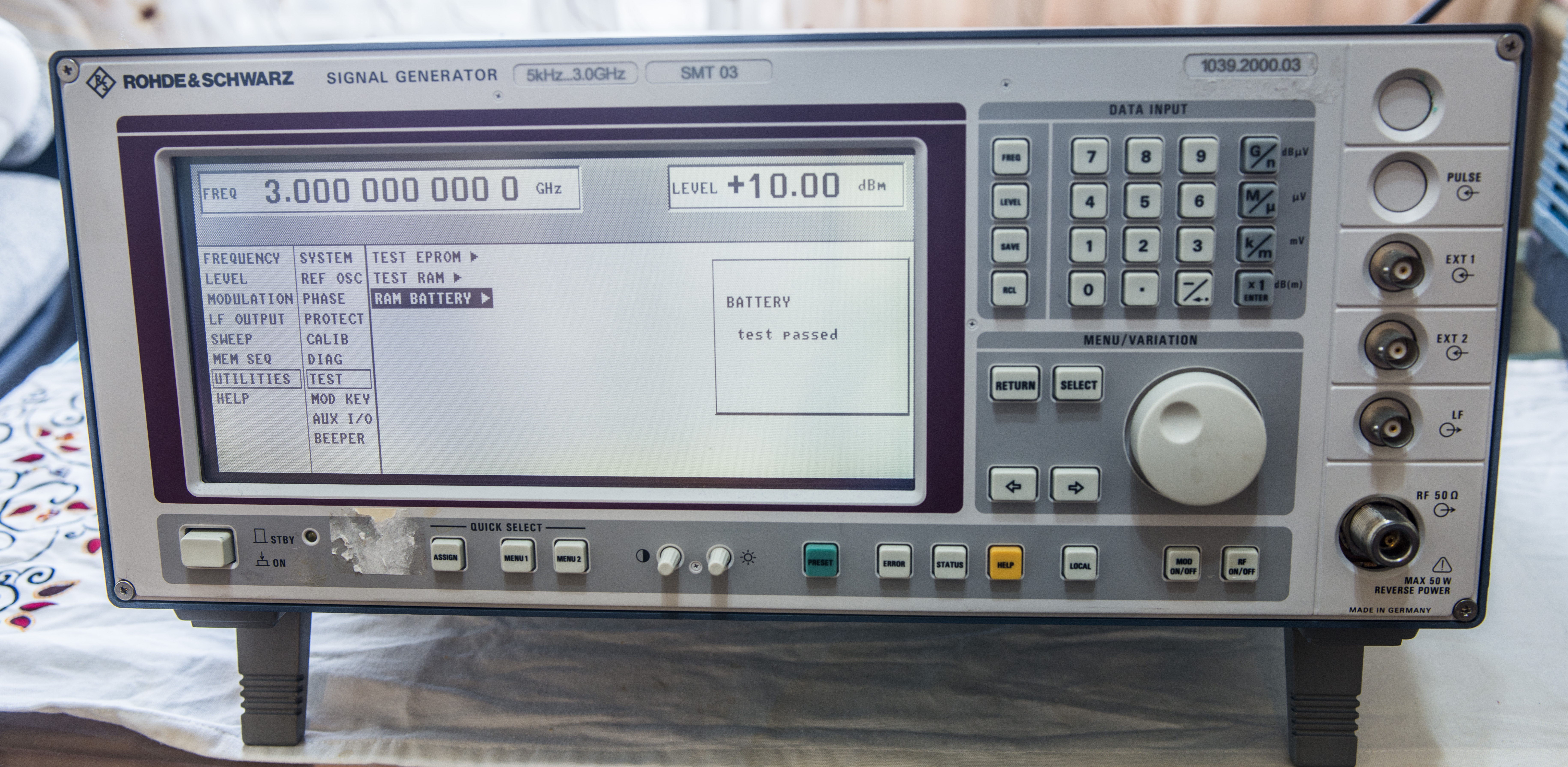
Instruments status and self-diagnostics
Internal test for EPROM, RAM and battery
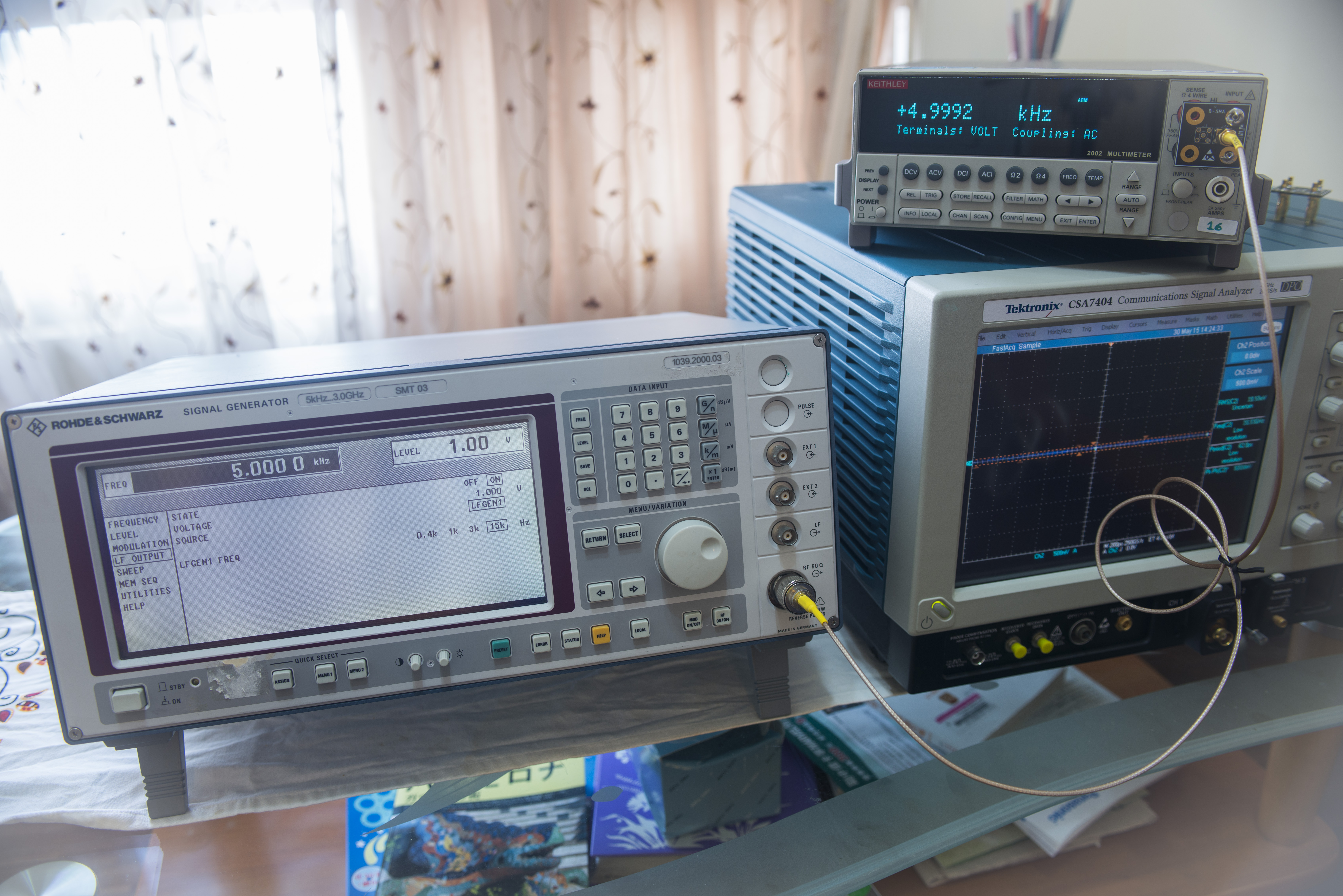
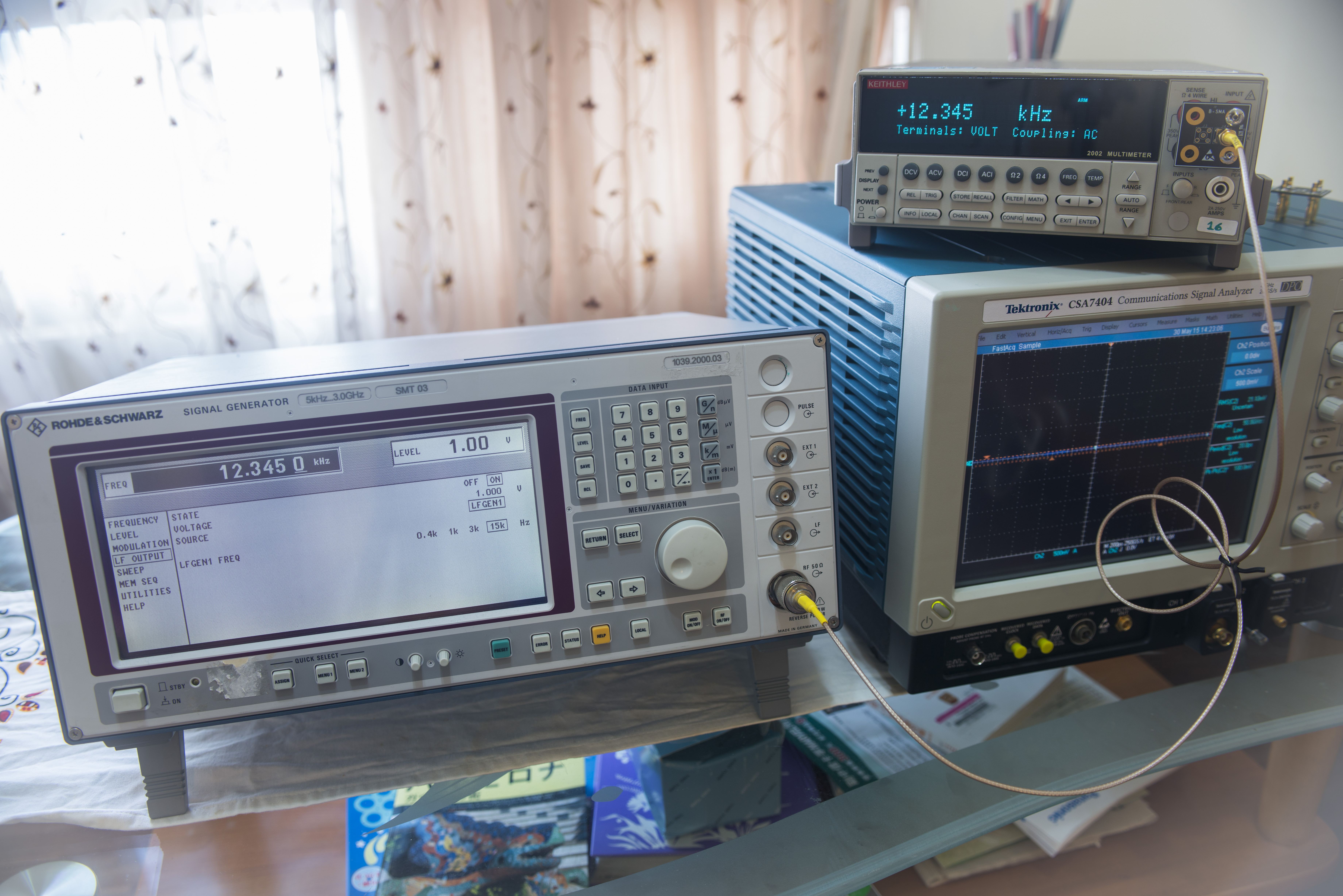
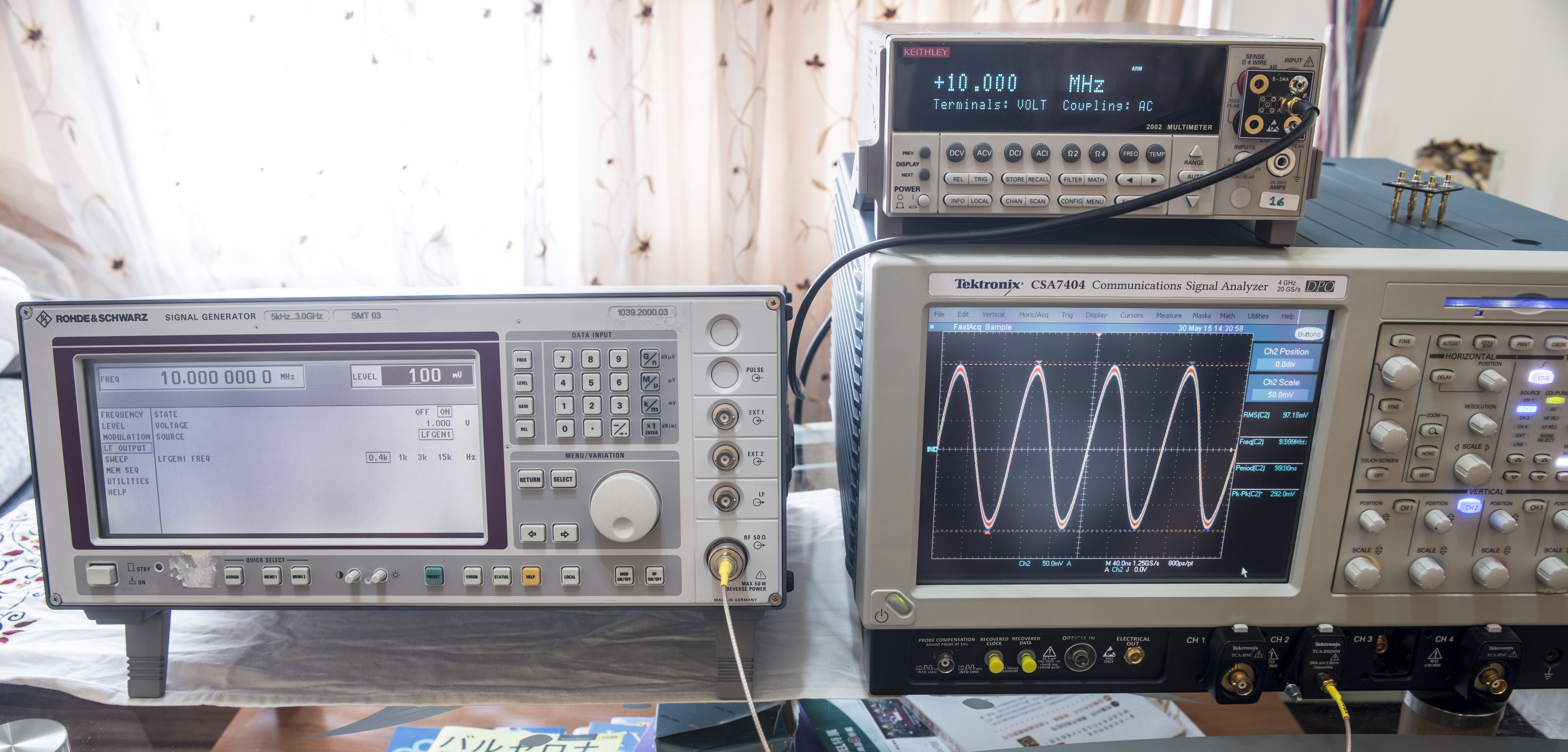
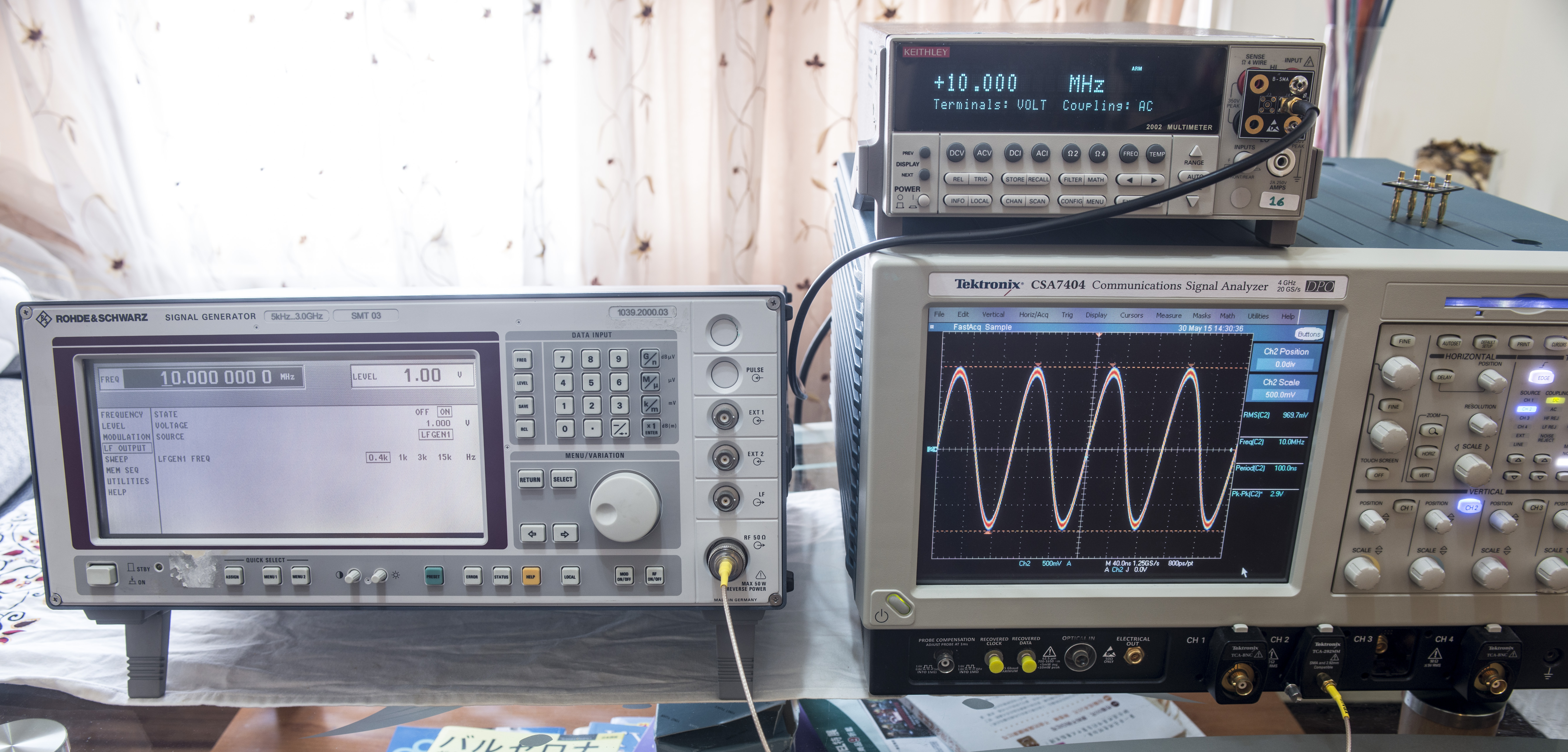
Low frequency output check:


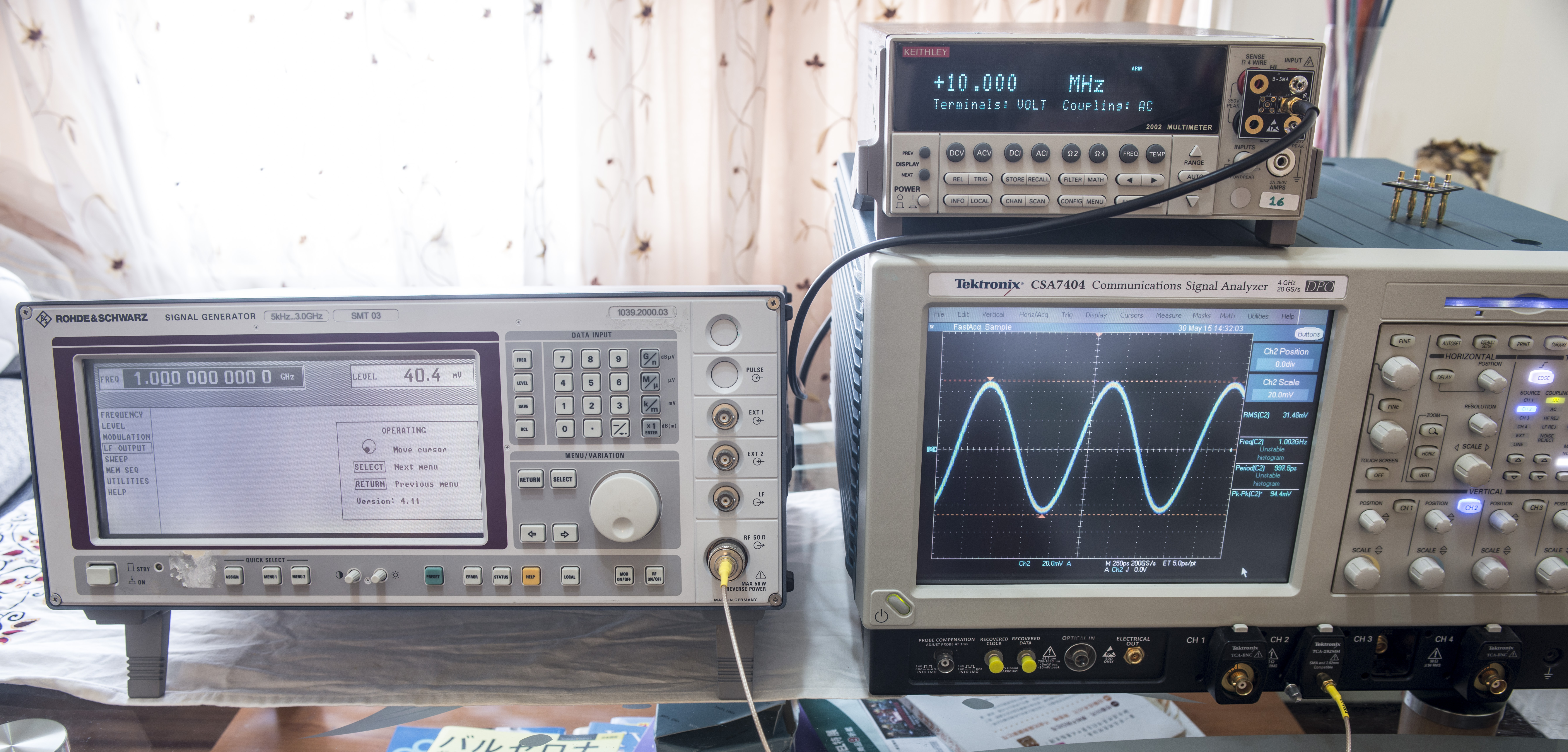
1Ghz & 3GHz output test
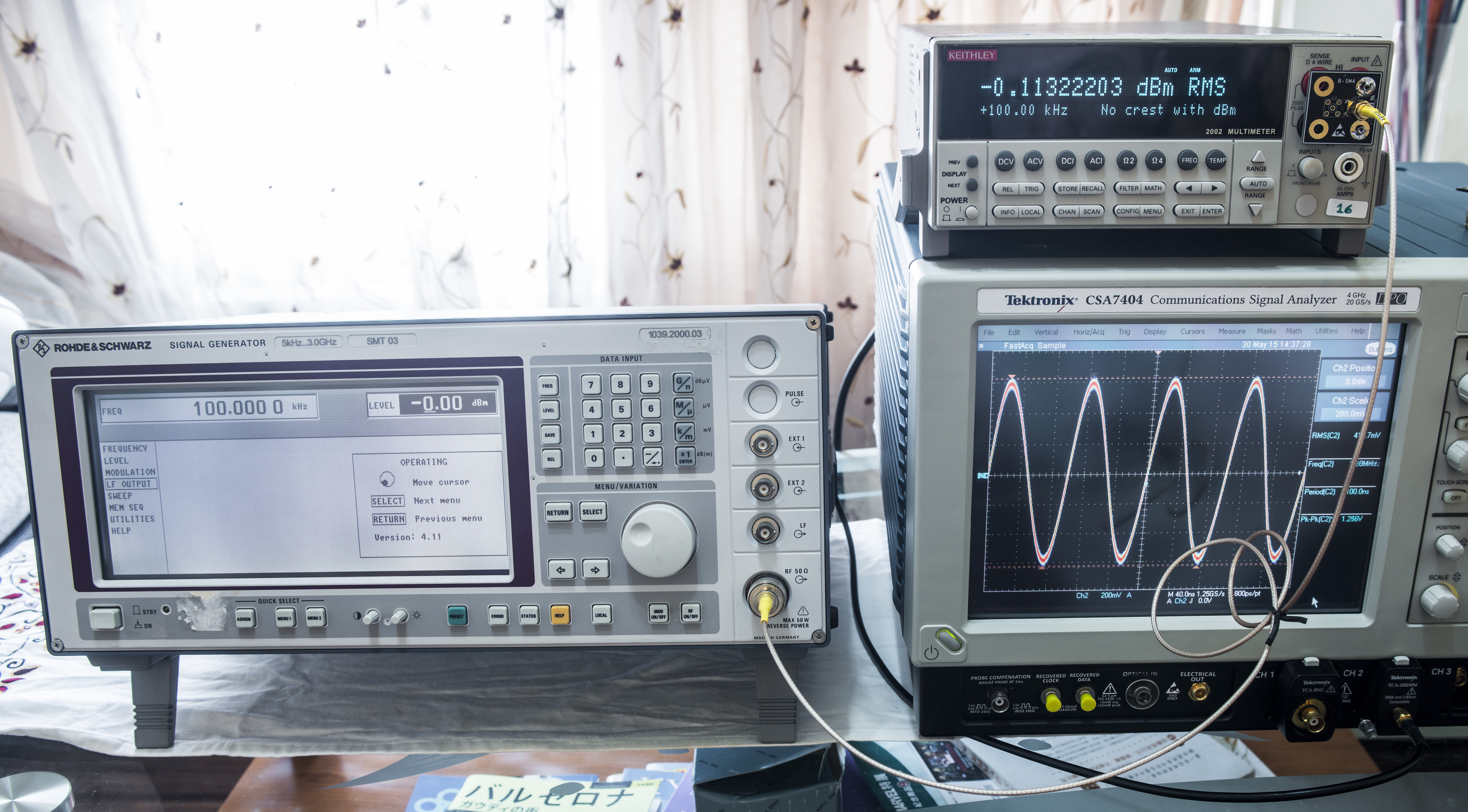
Amplitude check
Log scale check, 0dbm and -50dbm
Modulation check
Modified: July 22, 2015, 5:35 p.m.