Often overclocking in search if higher performance of computer hardware require increasing operation voltages. In most extreme cases, onboard power regulators is unable to cope with much higher currents and voltages, and as a solution external power modules are used. One of these modules is EVGA EPOWER CLASSIFIED device. It is available for technology enthusiasts with limited DOA warranty.
Basically module is a multi-phase synchronous buck DC-DC convertor which takes +12V input voltage and regulates it down to 0.6-2.0V, providing over 400 Amps of current.
Since different applications may need different output voltages, in this article we will cover four possible ways to adjust voltage on the fly, at any time device is operating.
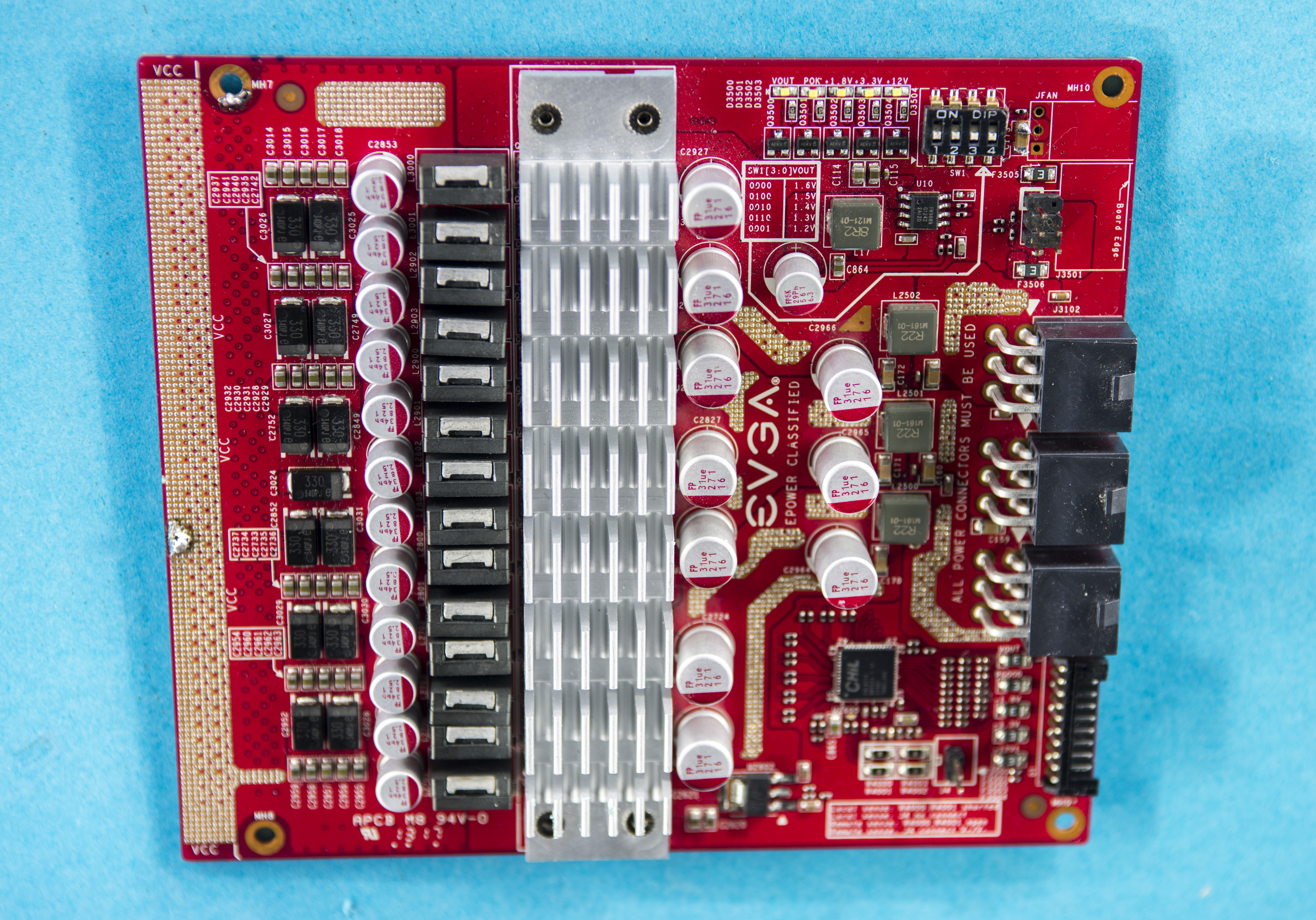

Board accepts input voltage by standard MiniFit Jr 6-pin connectors, following PCIe VGA power pin definition. Input voltage range is +10.6 to +13.2 VDC, power supply rated input power should be at least 800W.
All three connectors must be used, as different phases taking power from separate connectors. Main power stage train using 14 phases, using IRF DirectFETs. Output voltage provided on exposed PCB copper edge on component side,
and ground return is exposed on bottom side of board. Good ventilation is highly recommended for optimal performance with higher power levels.
Disclaimer
Before we dig deep into details, here’s necessary part to notice:
Redistribution and use of materials in this article or any files referenced in it, in source and binary forms, with or without modification, are permitted provided that the following conditions are met:
- Redistributions of article must retain the above copyright notice, this list of conditions, link to this page (http://xdevs.com/guide/epower_mod/) and the following disclaimer.
- Redistributions of files in binary form must reproduce the above copyright notice, this list of conditions, link to this page (http://xdevs.com/guide/epower_mod/), and the following disclaimer in the documentation and/or other materials provided with the distribution, for example Readme file.
All information posted here is hosted just for education purposes and provided AS IS. In no event shall the author, this site, or any other 3rd party, including EVGA be liable for any special, direct, indirect, or consequential damages or any damages whatsoever resulting from loss of use, data or profits, whether in an action of contract, negligence or other tortuous action, arising out of or in connection with the use or performance of information published here.
Using onboard DIP-switch to control EVGA EPOWER CLASSIFIED output voltage (up to 1.65 V)
| Output voltage | DIP switch position | |||
| 1 | 2 | 3 | 4 | |
| 894 mV | OFF | OFF | OFF | OFF |
| 950 mV | OFF | OFF | OFF | ON |
| 1020 mV | OFF | OFF | ON | OFF |
| 1052 mV | OFF | OFF | ON | ON |
| 1105 mV | OFF | ON | OFF | OFF |
| 1157 mV | OFF | ON | OFF | ON |
| 1210 mV | OFF | ON | ON | OFF |
| 1262 mV | OFF | ON | ON | ON |
| 1315 mV | ON | OFF | OFF | OFF |
| 1366 mV | ON | OFF | OFF | ON |
| 1420 mV | ON | OFF | ON | OFF |
| 1472 mV | ON | OFF | ON | ON |
| 1525 mV | ON | ON | OFF | OFF |
| 1577 mV | ON | ON | OFF | ON |
| 1630 mV | ON | ON | ON | OFF |
| 1682 mV | ON | ON | ON | ON |
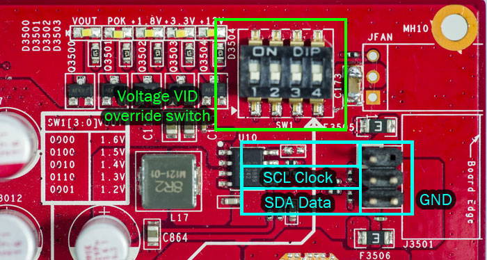
Adjusting voltage is possible with toggling 4-position switch SW1. It’s located near top right corner of EPOWER board, just near
FAN and EVBOT interface connector. Switch can be adjusted any time, unless voltage setting is overridden by digital setting (from I2C command).
Using variable resistor to control EVGA EPOWER CLASSIFIED output voltage
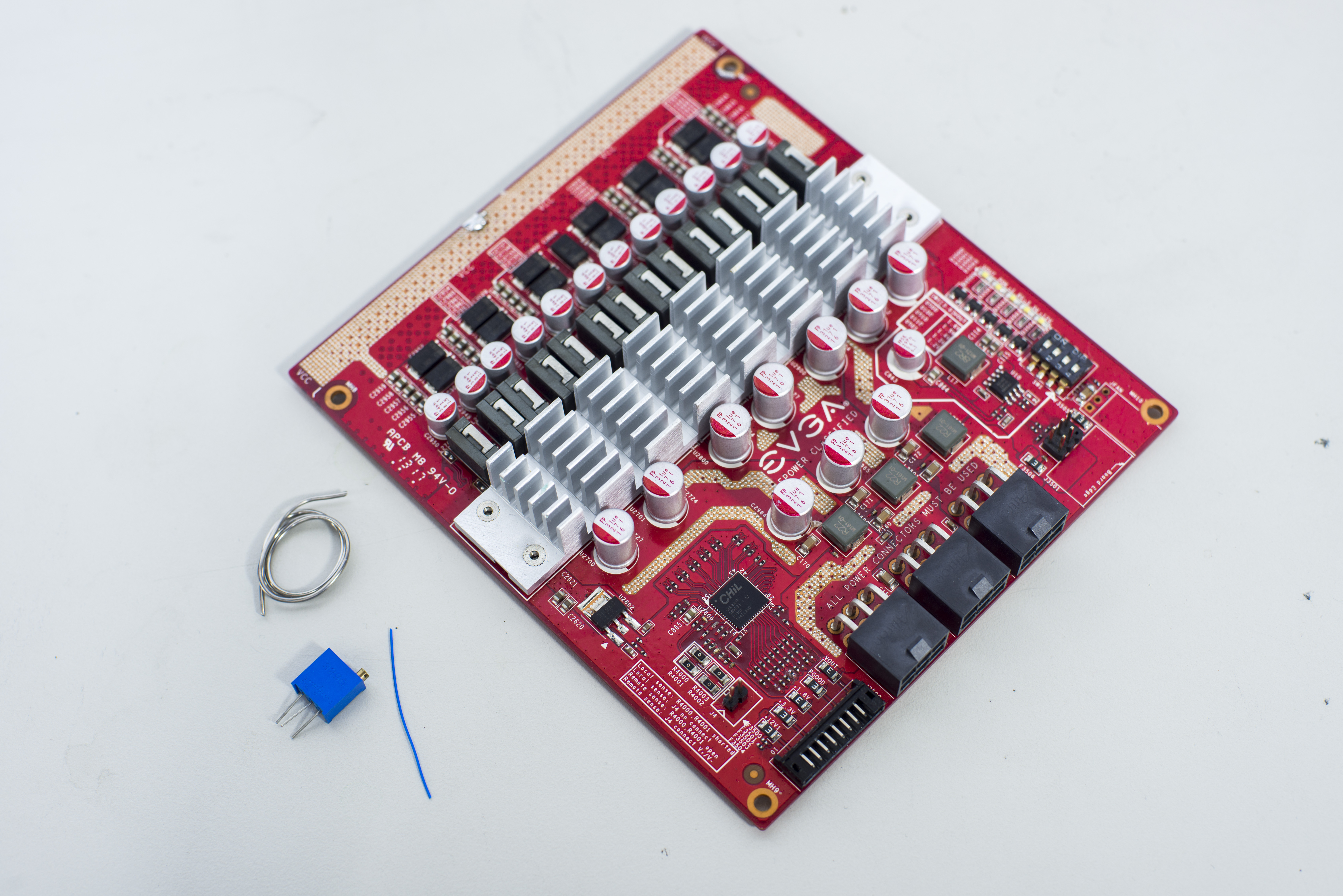
If you need finer steps than DIP-switch method provide, or require voltage output higher than 1.68V, you can add trim pot resistor to offset voltage setting.
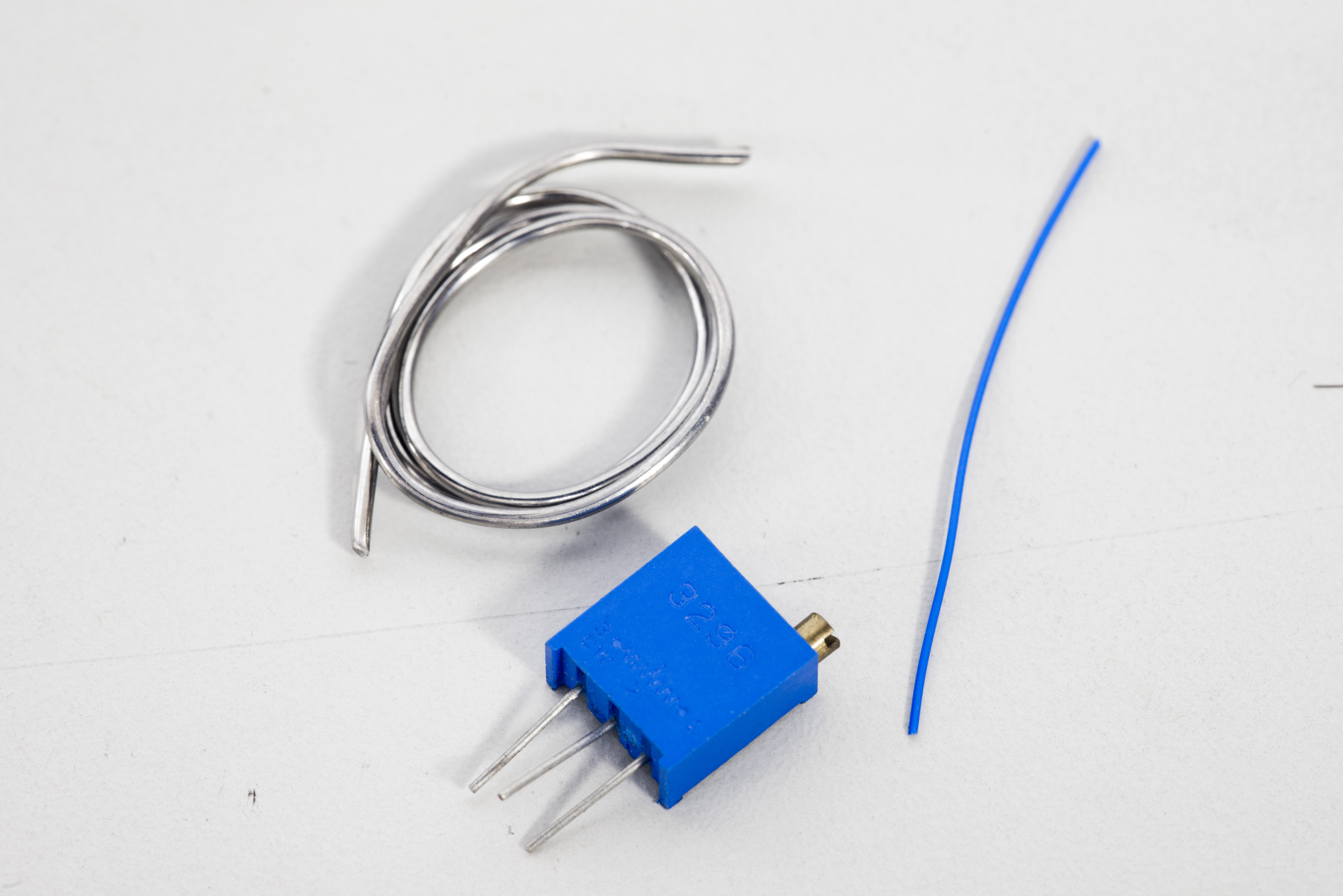
To do so you will need:
- 1 kOhm multi-turn variable resistor, such as 3296 size 3-terminal resistor
- Soldering iron
- Small piece of insulated wire
- Multimeter
You can use also 500 ohm or 2K resistor, if don’t have exact 1K.
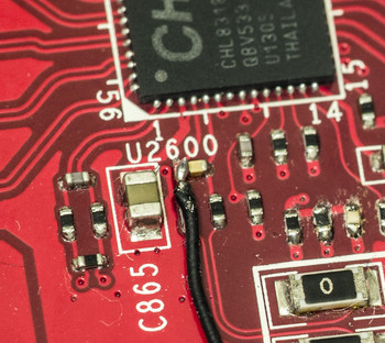
First remove solder mask in bottom right corner, like shown on photo below. This will be our ground connection spot.
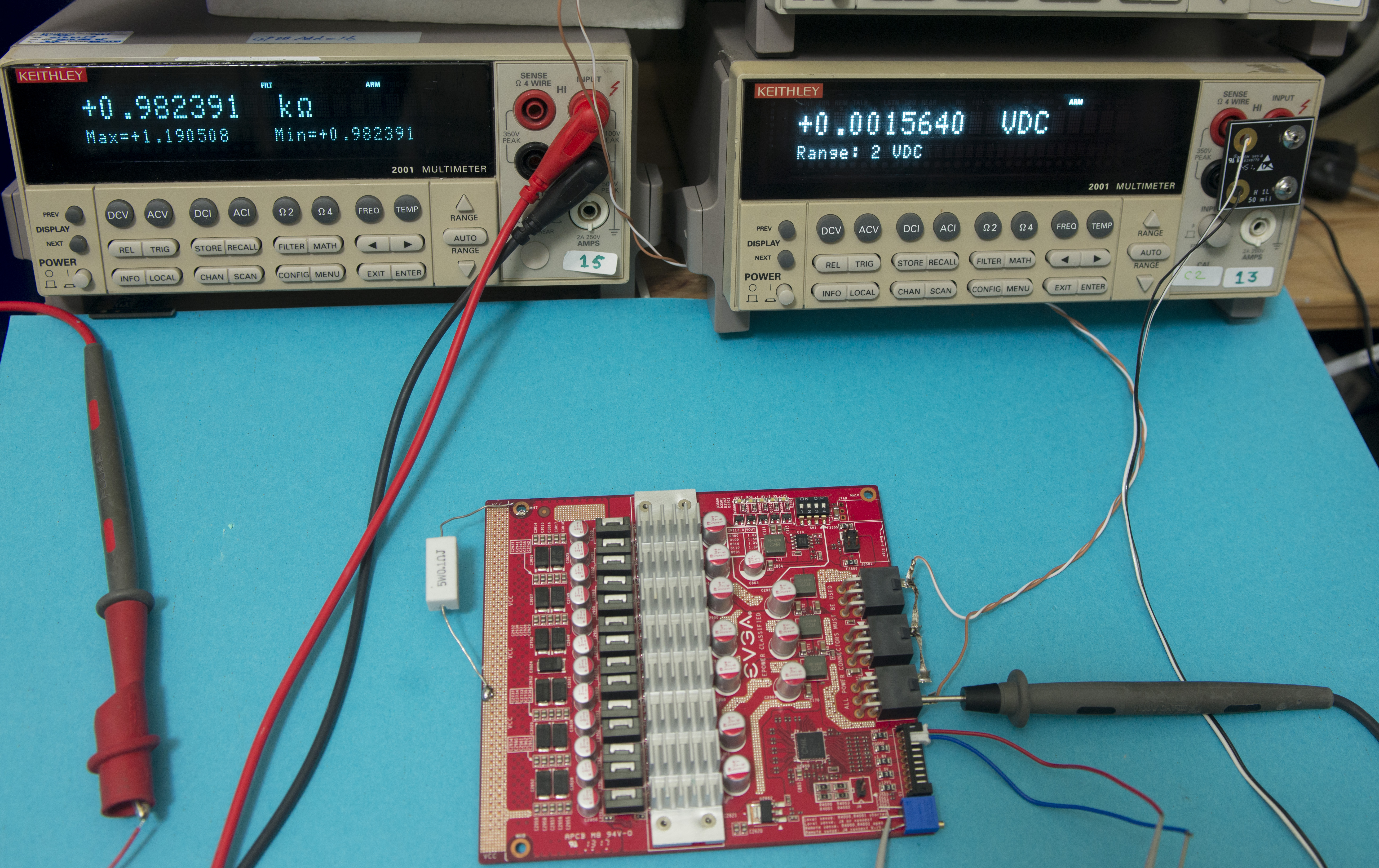
Then measure resistor middle terminal and adjust resistor for maximum resistance. In our case it was 984 ohm.
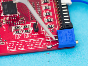
Now connect middle terminal with small wire to capacitor left side, like shown.
Check all connections and make sure nothing else got shorted.
Original stock condition (shown on photo at left side) have 0.9V as default settings (all VID switches off) and resistance to ground on capacitor terminal reads near 100 ohms. To properly measure resistance, output is required to be shorted
or connected to low-resistance load, as this is part of feedback network. In our case 0.1 ohm resistor was used as a load.
Added trim resistor reduced resistance to 74.5 ohm, which raised output voltage ~300mV, resulting 1.200 VDC. Pay attention as you still can set voltages by VID switch or digitally, but now your output voltage will be with positive offset 300mV. So if you set 1.630V by switch, you will get now 1.930V or about that.
Using EVGA EVBOT to control EVGA EPOWER CLASSIFIED output voltage (up to 1.85 V)
If you happen to have EVBOT controller, you can use it to adjust output voltage by simply connecting to 5-pin digital port at EPOWER. You will need EVGA EPOWER V25 firmware flashed to your EVBOT.
Flashing can be done by either EVGA motherboard (with EVBOT port, such as X58,X79,P67,Z68 series), of EVGA VGA card (Classified and K|NGP|N series cards) utility.
- Connect the EVBot cable to the MB port located on the EVBot device.
- Connect the other end of the EVBot cable to your graphics card.
- Extract contents of above .zip file and run EVBotFlashTool.exe
- Select the .hex file for flashing.
- Hold down the EVBot POWER button for 7 seconds until you see the EVBot screen display FLASH MODE.
- Click OK in EVBot Flash Tool to being the flashing process.
- After flash is complete, unplug EVBot, then plug it back in to any EVBot port.
This can be done using one of next VGA cards:
- EVGA GeForce GTX 285 Classified
- EVGA GeForce GTX 580 Classified
- EVGA GeForce GTX 680 Classified
- EVGA GeForce GTX 770 Classified
- EVGA GeForce GTX 780 Classified
- EVGA GeForce GTX 780Ti Classified (both normal and KPE)
- EVGA GeForce GTX 980 Classified (both normal and KPE)
- EVGA GeForce GTX 980Ti Classified (both normal and KPE)
- EVGA GeForce GTX 1080 Classified
Using Raspberry Pi to control EVGA EPOWER CLASSIFIED output voltage
You can use widely available RPI to talk with voltage regulator controller on EPOWER via I2C bus. EPOWER CLASSIFIED is using CHIL CHL8318 PWM controller, which accepts VID override digitally from PMBus.
Product brief for CHL8318 describe it as:
- 8-phase digital synchronous buck controller for core regulation of high-performance INTEL® VR11.1 and VR11.0 platforms.
- Fully compliant with VR11.1 including PSI and for improved light load efficiency and accurate current output (IMON).
- Customized Digital Overclocking Features
- Easy-to-use SMBus Gamer command
- Gamer VID control up to 2.3V, Gamer Vmax,VID Override or Track, Digital Load-Line Adjust,Gamer OC/OVP, Gamer OFF pin, Gamer OTP
Gamer VID it is, that’s the function which we will use.
Due to safety reasons, we will cap maximum output voltage to 2V, as most modern VGA cards have capacitors on Vcore rated only up to 2V.
Solid capacitors may have nasty explosions and fire if overvoltage happens.
To get started connect your Raspberry Pi I2C interface to EVGA EPower
EVBOT Pinout and connection map is shown in table below:
| Raspberry Pi signal name | Raspberry Pi Pin | EVBOT Pin |
|---|---|---|
| Ground | Pin 9 on header P1 | Pin 6 on header J3501 |
| I2C Data, SDA | Pin 3 on header P1 | Pin 5 on header J3501 |
| I2C Clock, SCL | Pin 5 on header P1 | Pin 3 on header J3501 |
EVBOT Pinout is next (looking at connector’s face):
| Pin 1 | |
| Pin 3 SCL | Pin 4 |
| Pin 5 SDA | Pin 6 GND |
Now you can power everything on, and connect to Raspberry Pi terminal.
Download next tool and put into Pi’s disk storage.
ELF-executable for Raspberry Pi Linux [using I2C1 port]
ELF-executable for Raspberry Pi Linux [using I2C0 port]
This little voltage setting tool was compiled and tested on Raspberry Pi B v2.0, running wheezy image.
/repo/epower# uname -a
Linux tin.pi 3.12.35+ #730 PREEMPT Fri Dec 19 18:31:24 GMT 2014 armv6l GNU/Linux
/repo/epower#
/repo/epower# /opt/vc/bin/vcgencmd version
Dec 19 2014 18:44:06
Copyright (c) 2012 Broadcom
version 5abd572e2ed1811283443387af09377b95501c50 (clean) (release)
Select correct version for either I2C0 port (it need modify your Pi to add header for it), or default I2C1 port, available on main header at pins 3 and 5.
Tool requires wiringPi library installed, with i2c enabled.
If EPOWER cannot be detected, tool will issue error and exit, like below:
%{color: blue}/***** EVGA EPOWER CLASSIFIED Manual VID setting tool ************/%
%{background: #f00; color:yellow}/!\ ERROR : No valid I2C0 device found, aborting..%
Or in case of I2C1 version:
%{color: blue}/***** EVGA EPOWER CLASSIFIED Manual VID setting tool ************/%
%{background: #f00; color:yellow}/!\ ERROR : No valid I2C1 device found, aborting..%
If that happens, check that I2C bus is accessible, and all connection between Pi and EPOWER is correct.
Using i2c-tools i2cdetect with proper connection should give you present devices on address 0×0C and 0×46.
/home/pi# i2cdetect -y 0
     0  1  2  3  4  5  6  7  8  9  a  b  c  d  e  f
00:          -- -- -- -- -- -- -- -- -- 0c -- -- --
10: -- -- -- -- -- -- -- -- -- -- -- -- -- -- -- --
20: -- -- -- -- -- -- -- -- -- -- -- -- -- -- -- --
30: -- -- -- -- -- -- -- -- -- -- -- -- -- -- -- --
40: -- -- -- -- -- -- 46 -- -- -- -- -- -- -- -- --
50: -- -- -- -- -- -- -- -- -- -- -- -- -- -- -- --
60: -- -- -- -- -- -- -- -- -- -- -- -- -- -- -- --
70: -- -- -- -- -- -- -- --
After everything successfully detected, you can run tool, with output for example as below:
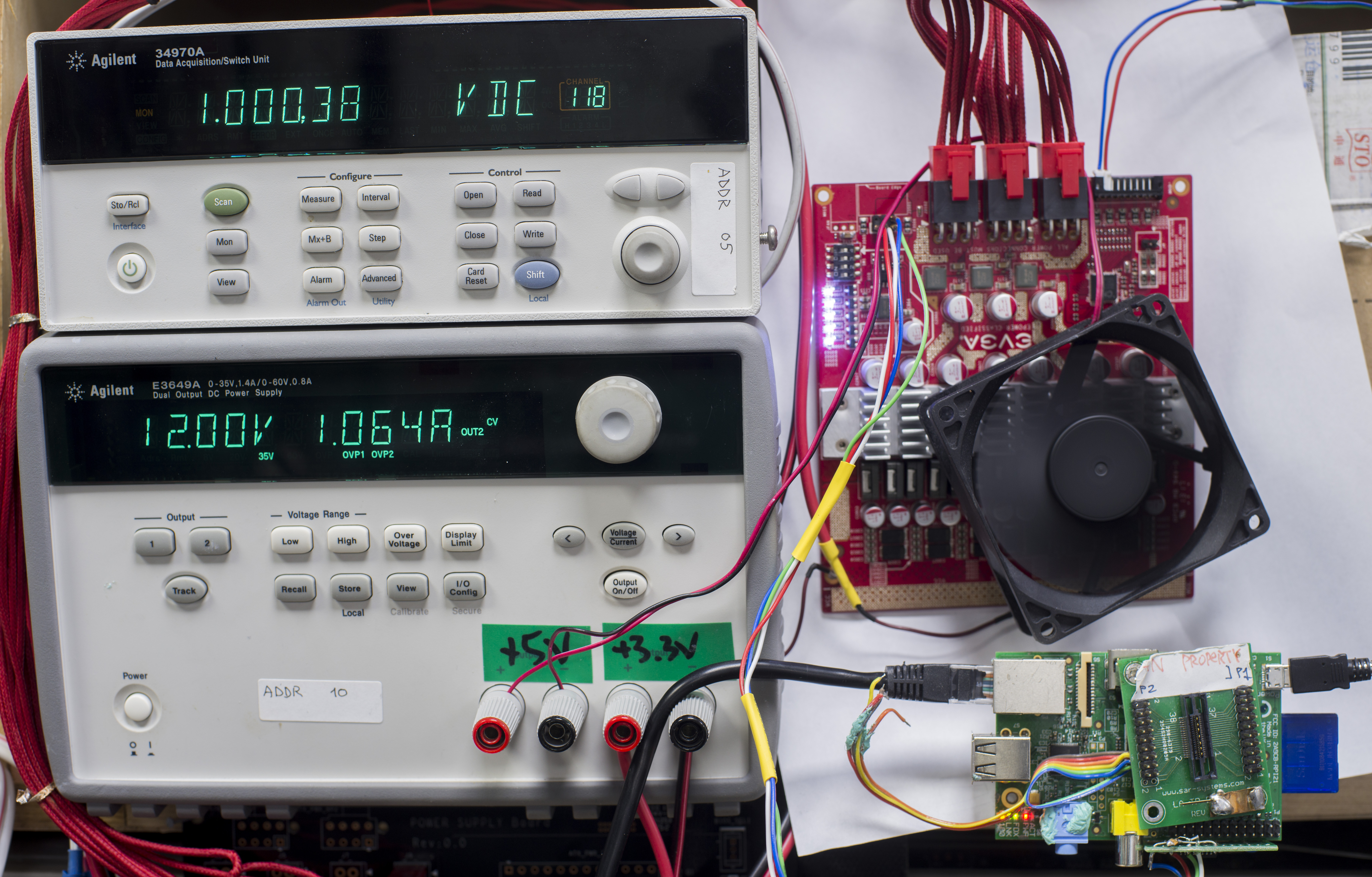
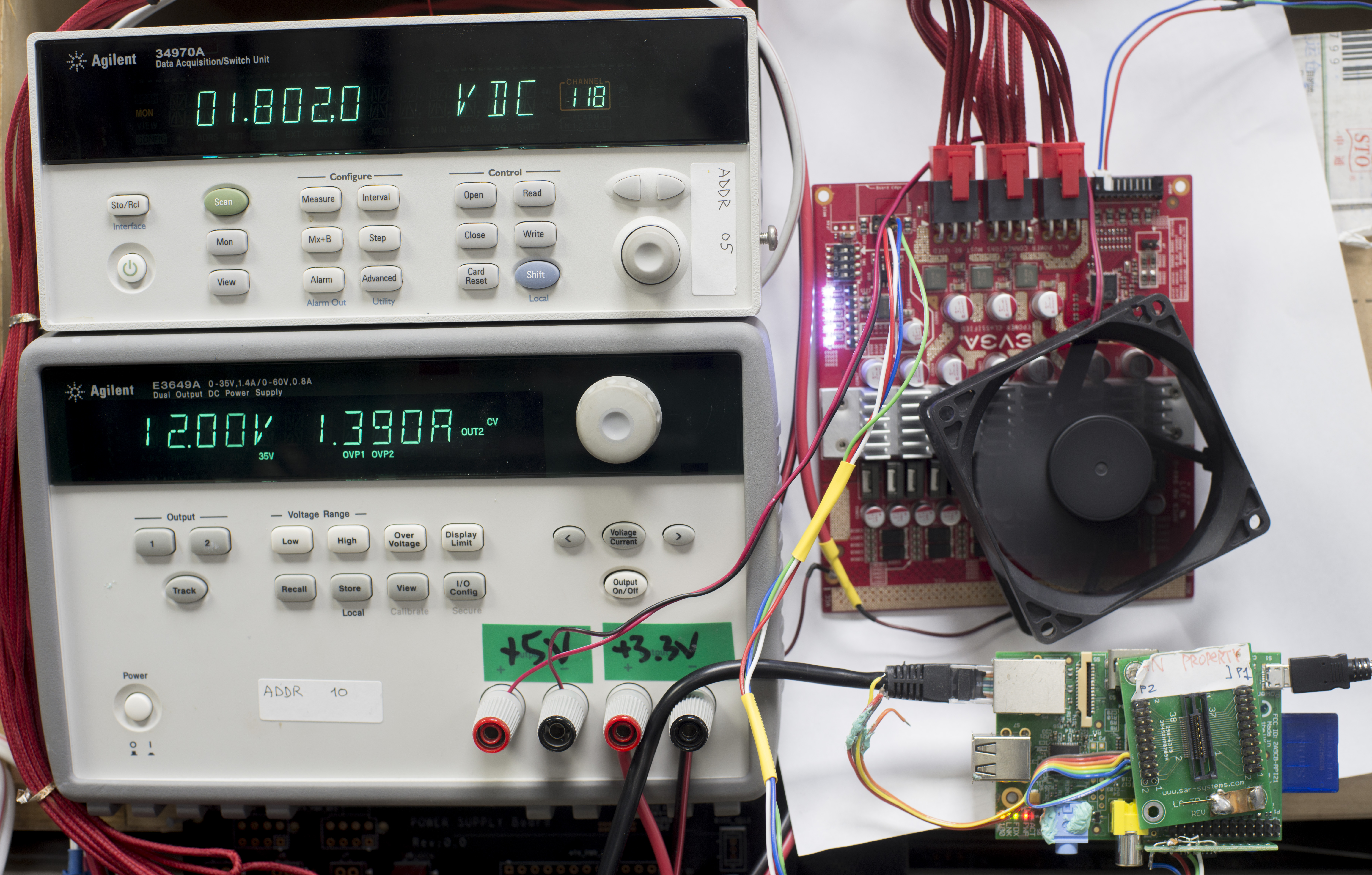
Here voltages in 100mV steps were entered, and actual readout values for input, output voltages and temperature was reported.
If user enter zero value into desired voltage request – tool will switch to monitoring mode, which will report current settings in infinite loop.
This could be handy to see if some protection, like OCP/OVP shutdowns output voltage during benching session.
Hope this will help to get higher overclocks and records out of your hardware.
Modified: Sept. 14, 2016, 7:18 a.m.