Intro
The MAXIM MAX31855PMB1 temperature interface breakout PCBA provides the necessary hardware to interface the MAXIM MAX31855 cold-junction compensated thermocouple-to-digital converter to any system that have SPI data port.
In this guide interfacing and use together with Raspberry Pi 3 will be covered. I needed this module to roughly measure liquid nitrogen temperatures, which are around 77K (-196 °C), and this is well within ability of the MAX31855K and high-quality K-type thermocouple probe.
This converter resolves temperatures to 0.25 °C, allows readings as high as +1800 °C and as low as −270 °C, and exhibits thermocouple accuracy of ±2 °C for temperatures ranging from −200 °C to +700 °C for K-type thermocouples. The data output in a signed 14-bit, SPI read-only format. MAX31855 exists in versions that operate with a K-, J-, N-, T-, R-, or E-type thermocouple. MAX31855PMB1 module feature K-version connector, set up to operate with standard K-type thermocouple.
MAX31855PMB1 features and specifications:
- Converts Output of a K-Type Thermocouple directly to a 14-Bit Digital data with sign
- Cold-Junction Compensation
- 14-Bit or 0.25°C Resolution
- Omega PCC-SMP-K thermocouple miniature PCB connector
- Detects Thermocouple failures, such as short to GND or VCC
- Detects open thermocouple condition
- 6-Pin PMOD-Compatible Connector (SPI port)
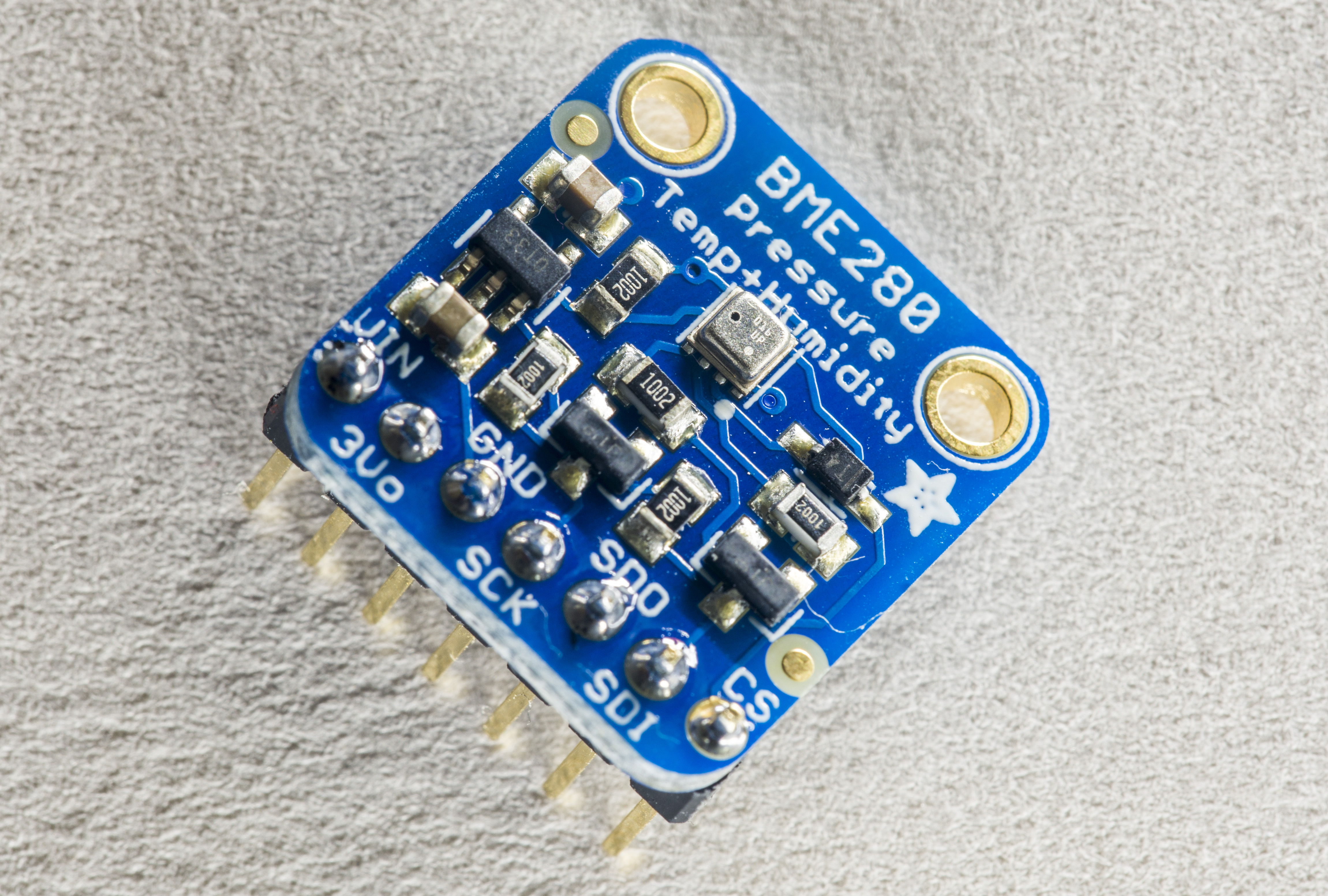
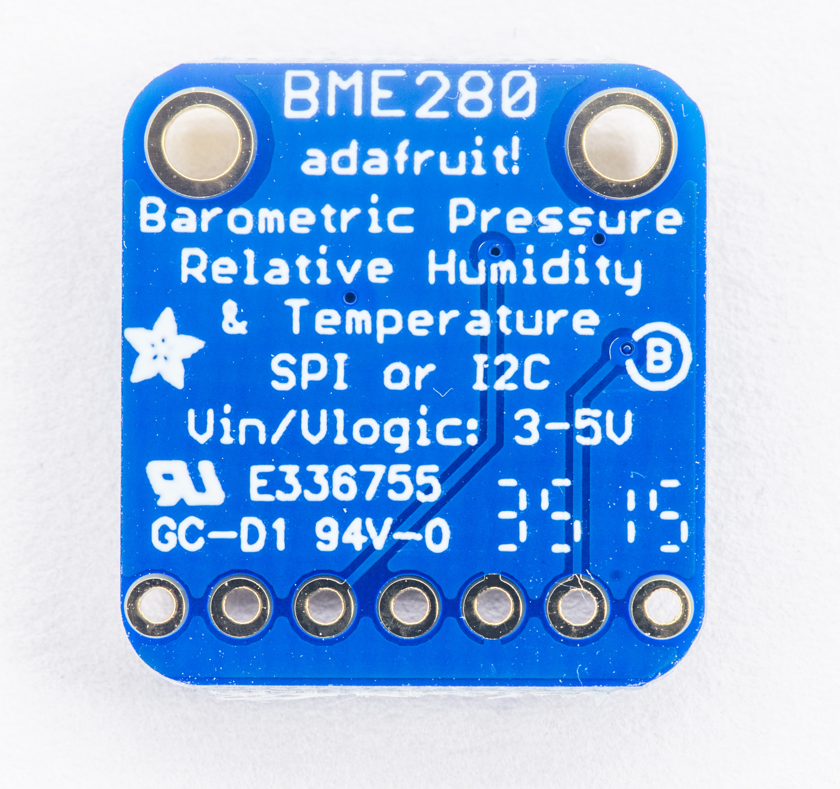
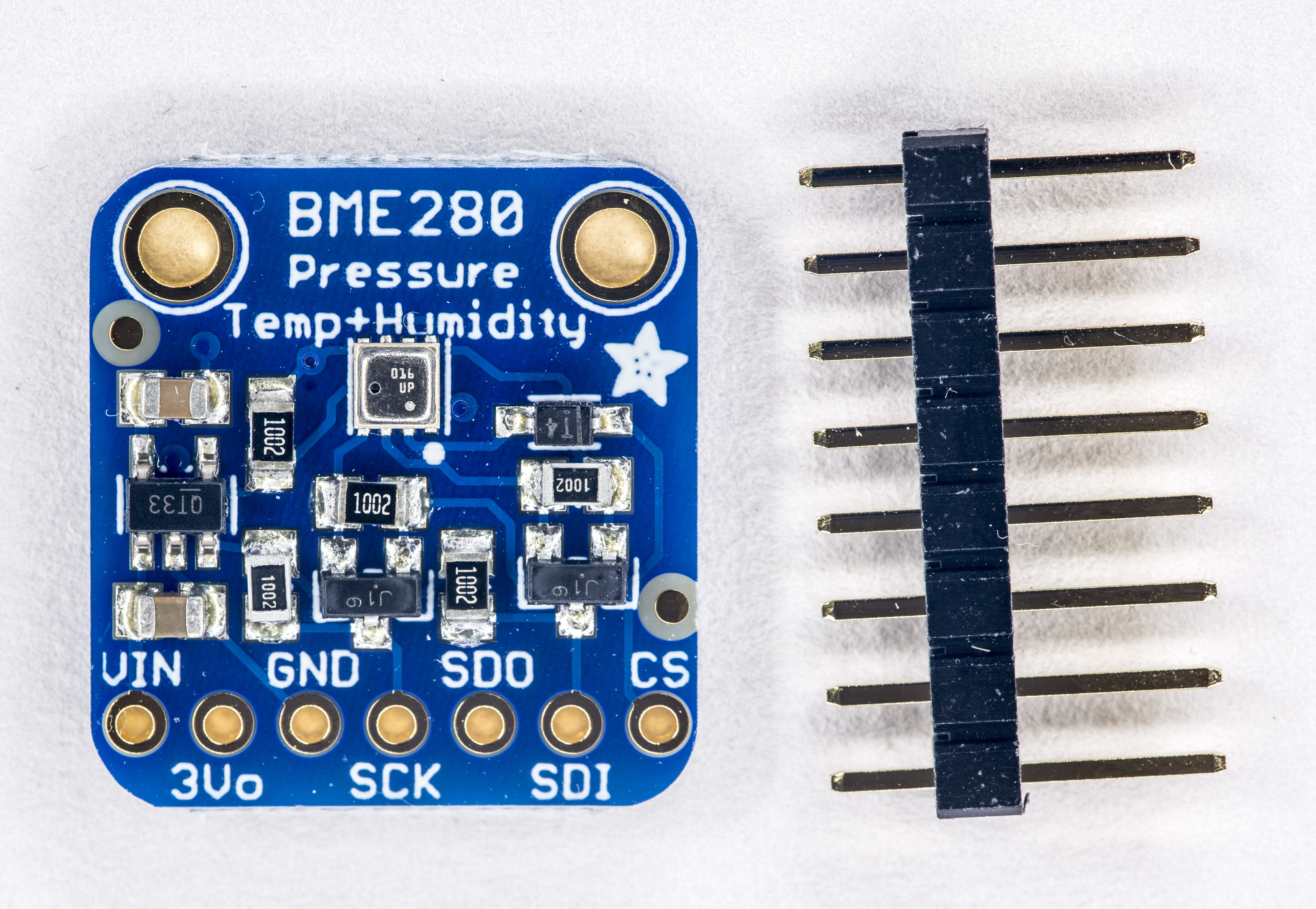
This module cost around $26 USD at major retailers, such as Digikey or Mouser. Adafruit also have similar Thermocouple Amplifier MAX31855 breakout board but without good quality Omega connector. Use of proper thermocouple connector is important to maintain sensor accuracy due to microvolt level signals and cold-junction compensation requirements.
MAXIM MAX31855PMB1 module datasheet
Connections to RPi
| Signal | Raspberry Pi 3 pin number | MAX31855PMB1 pin |
|---|---|---|
| Chip Select SSEL | Pin 24 | SS pin 1 |
| Data MISO | Pin 21 | MISO pin 3 |
| Clock SPCK | Pin 23 | SCK pin 4 |
| Power +3.3V | Pin 1 | 3.3V pin 6 |
| Ground | Pin 9 | GND pin 5 |
Don’t forget to get SPI enabled on your Pi, using raspi-config , if it’s not already on.
Raspberry Pi code and software setup
We can use adafruit’s python lib to test operation of MAX31855 and RPi.
Installation is easy:
sudo apt-get update
sudo apt-get install build-essential python-dev python-smbus
This should complete without any errors.
Now we get GIT repository trunk with Adafruit_Python_MAX31855 library, following same approach:
git clone https://github.com/adafruit/Adafruit_Python_MAX31855.git
Cloning into 'Adafruit_Python_MAX31855'...
remote: Counting objects: 58, done.
remote: Total 58 (delta 0), reused 0 (delta 0), pack-reused 58
Unpacking objects: 100% (58/58), done.
This will download library trunk and example code for Python. Now install it using python setup.py install.
cd /Adafruit_Python_MAX31855
python setup.py install
Check that there is no error. To test operation go to ./examples directory and execute:
#:/repo/Adafruit_Python_MAX31855/examples# python ./simpletest.py
Press Ctrl-C to quit.
Thermocouple Temperature: 20.517*C / 68.931*F
    Internal Temperature: 21.241*C / 70.234*F
Thermocouple Temperature: 20.582*C / 69.048*F
    Internal Temperature: 21.345*C / 70.421*F
That’s it. You can reference this example Python application, and reuse it in you own code.
Library for higher resolution MAX31856
For newer MAX31856 chip one can use this library instead.
Temperature controller for IR heating plate and MAX31856
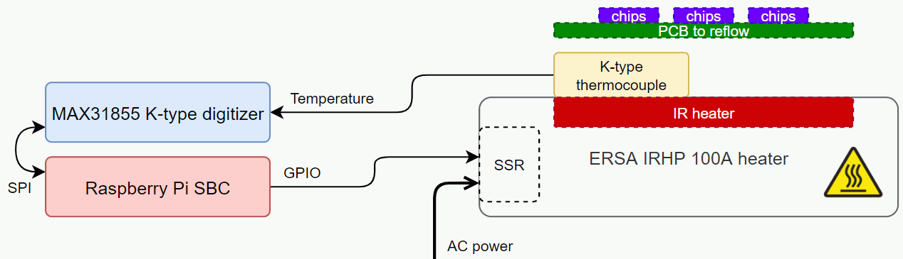
Below is actual practical example of Adafruit MAX31856 + Raspberry Pi to precisely control temperature of the ERSA IRHP 100A infrared heating plate for soldering BGA components on small PCB.
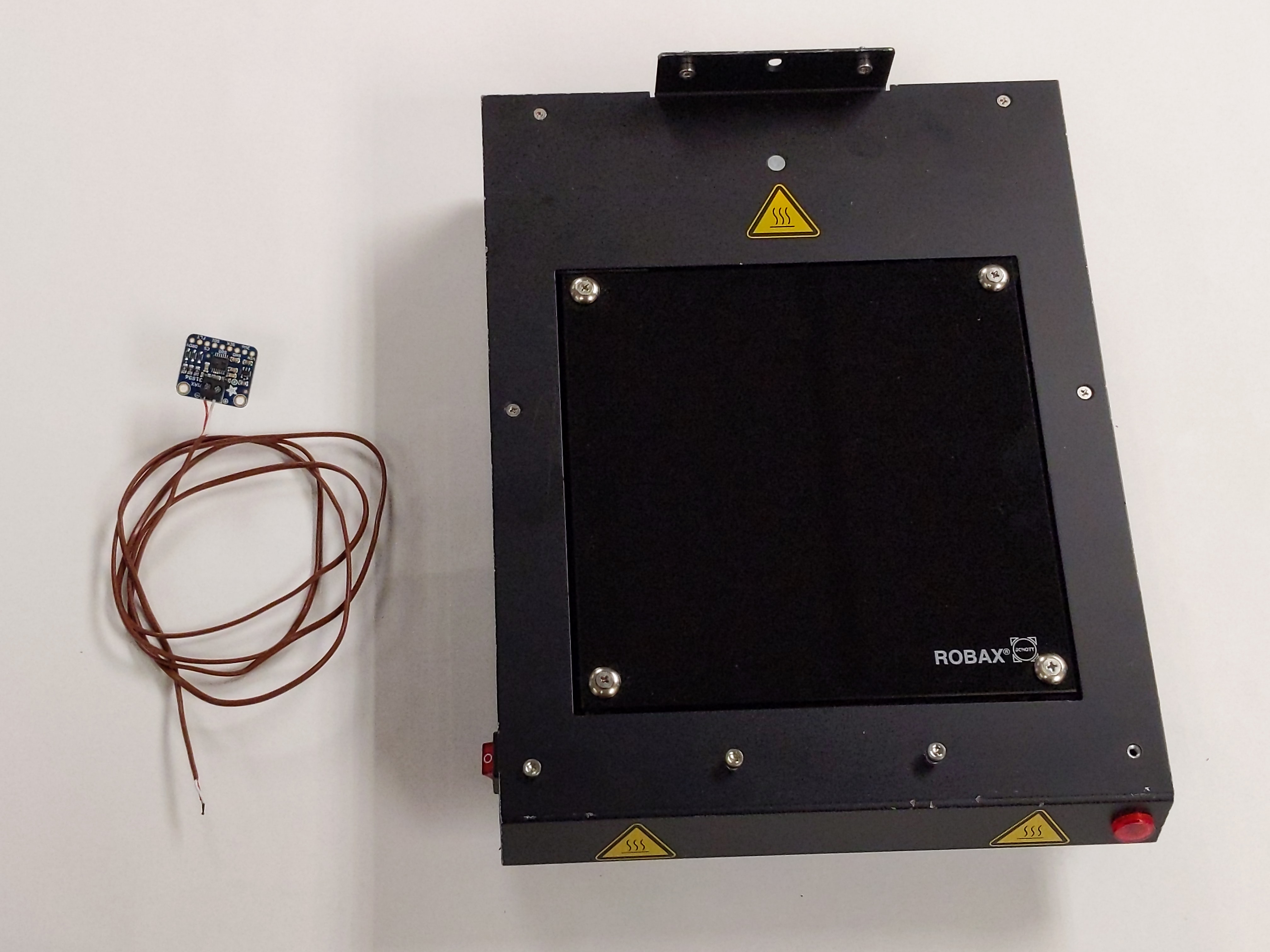
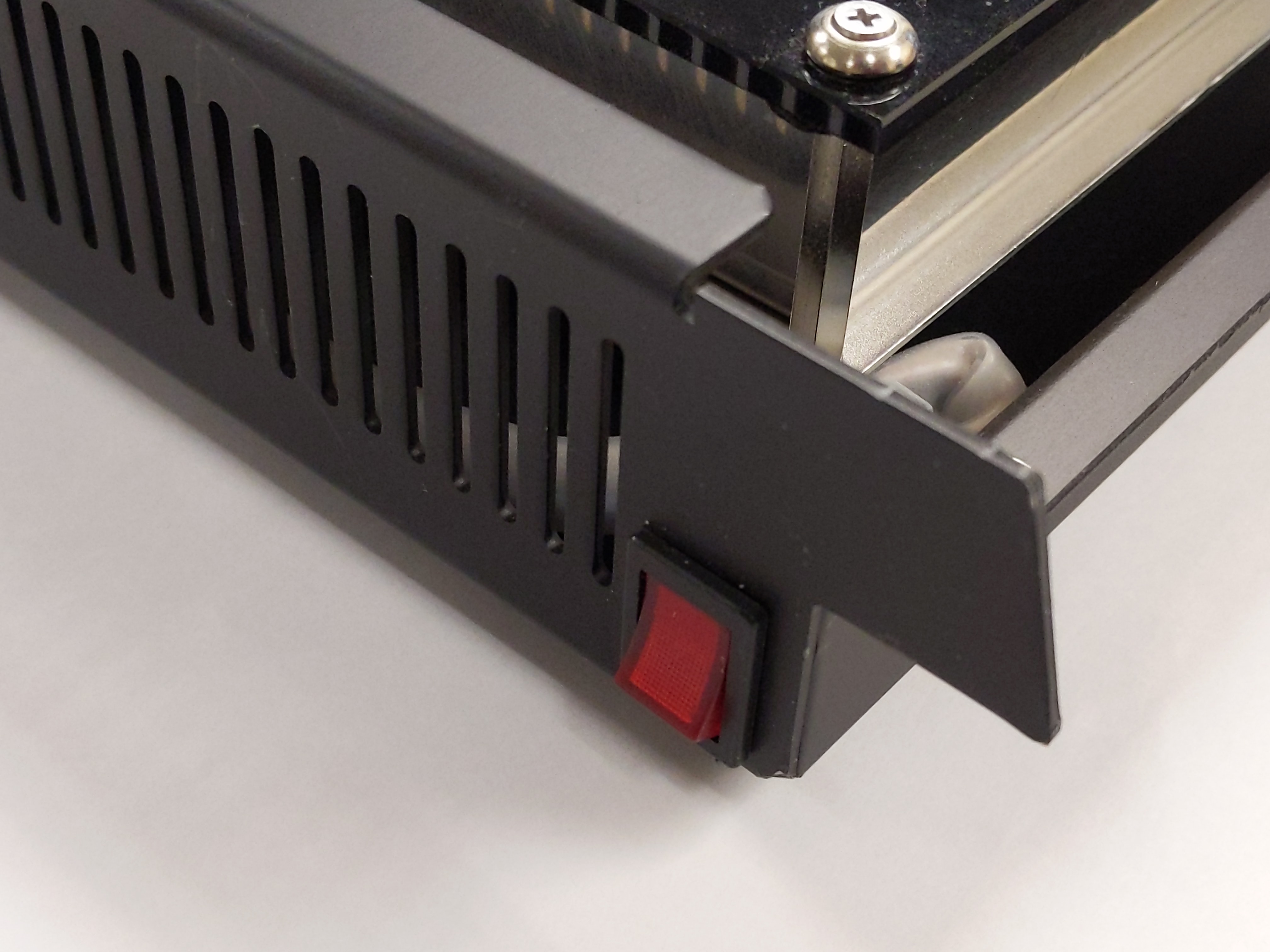
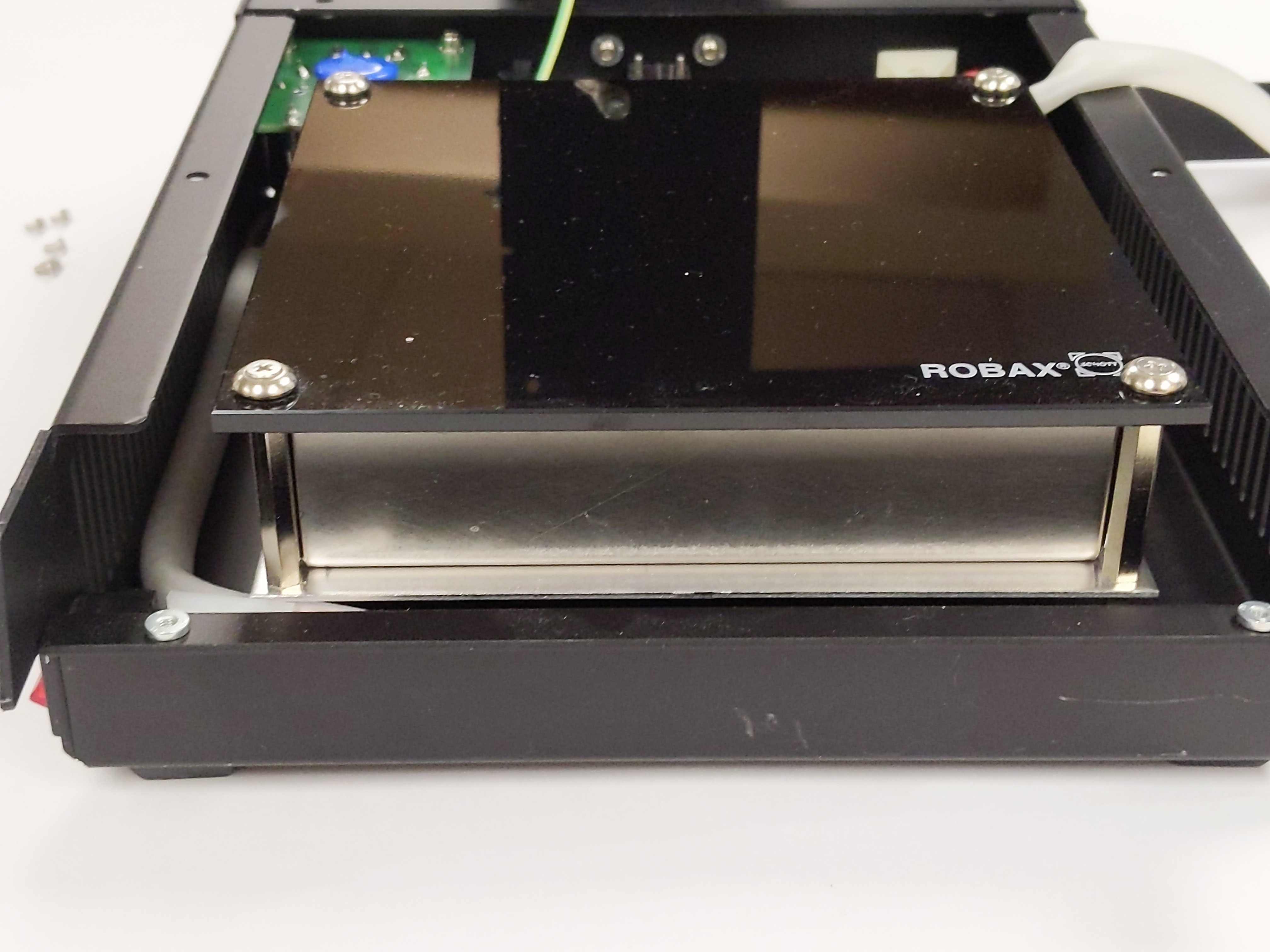
It is available in two version for 230 or 120 VAC mains and equipped with 800W infrared heater plate. Heater is thermally shielded and protected by top ROBAX glass-ceramic plate. This glass type has very small thermal expansion coefficient and designed for hot temperature uses.
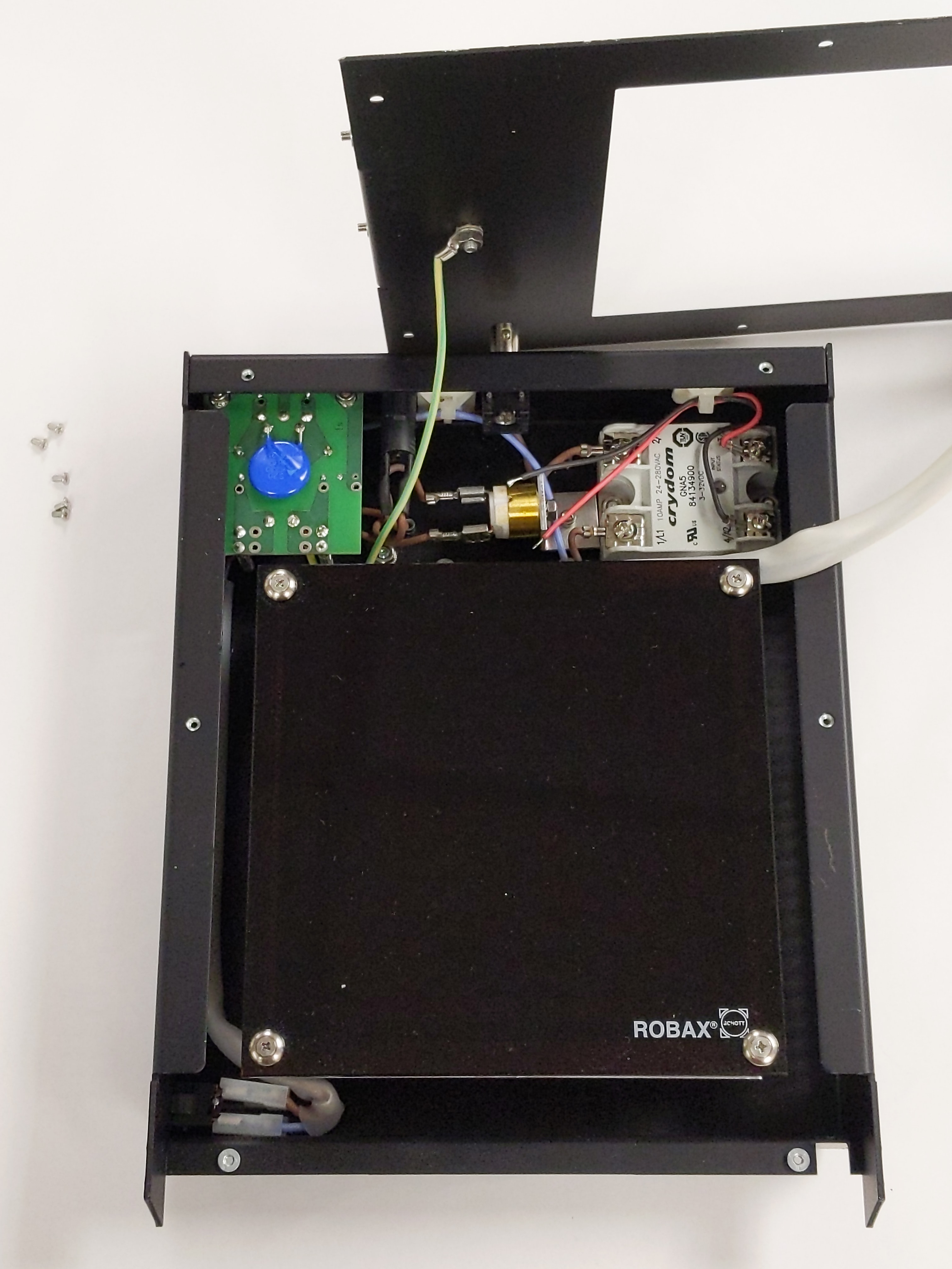
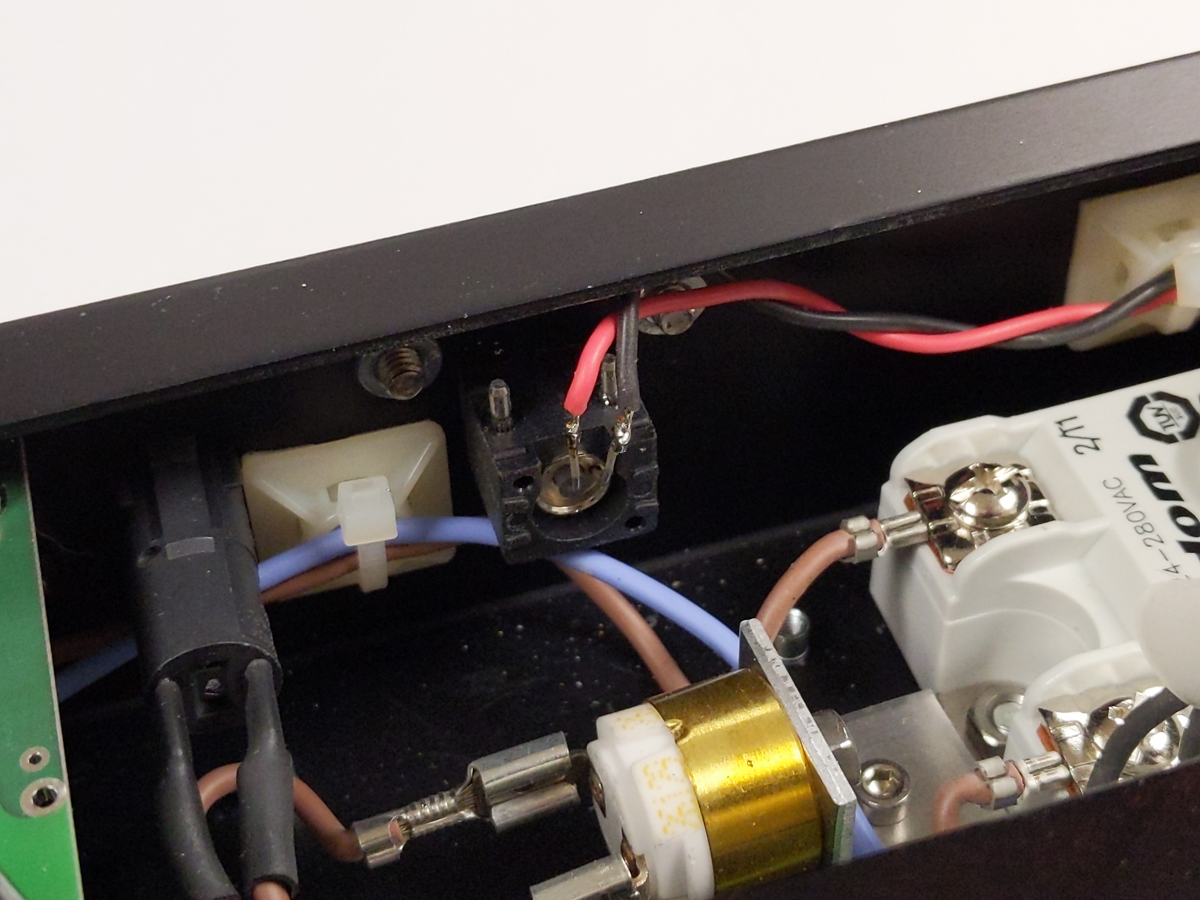
This plate has simple Crydom GNA5 solid-state relay to switch AC mains power to 800W heater plate. Control signal is accepted from external controller and should be in range from 3 to 32VDC. +3.3V level from RPi should work just fine here.
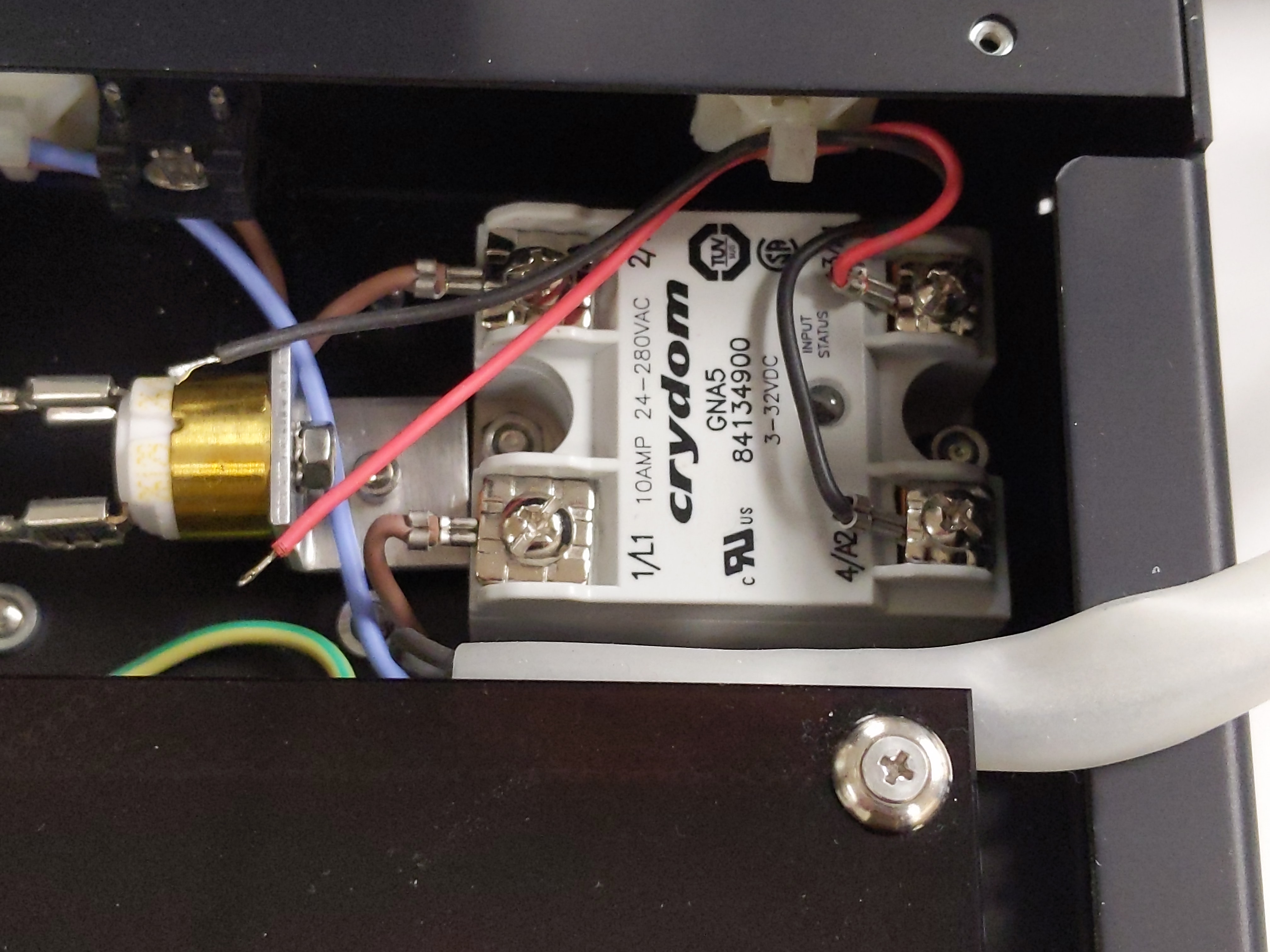
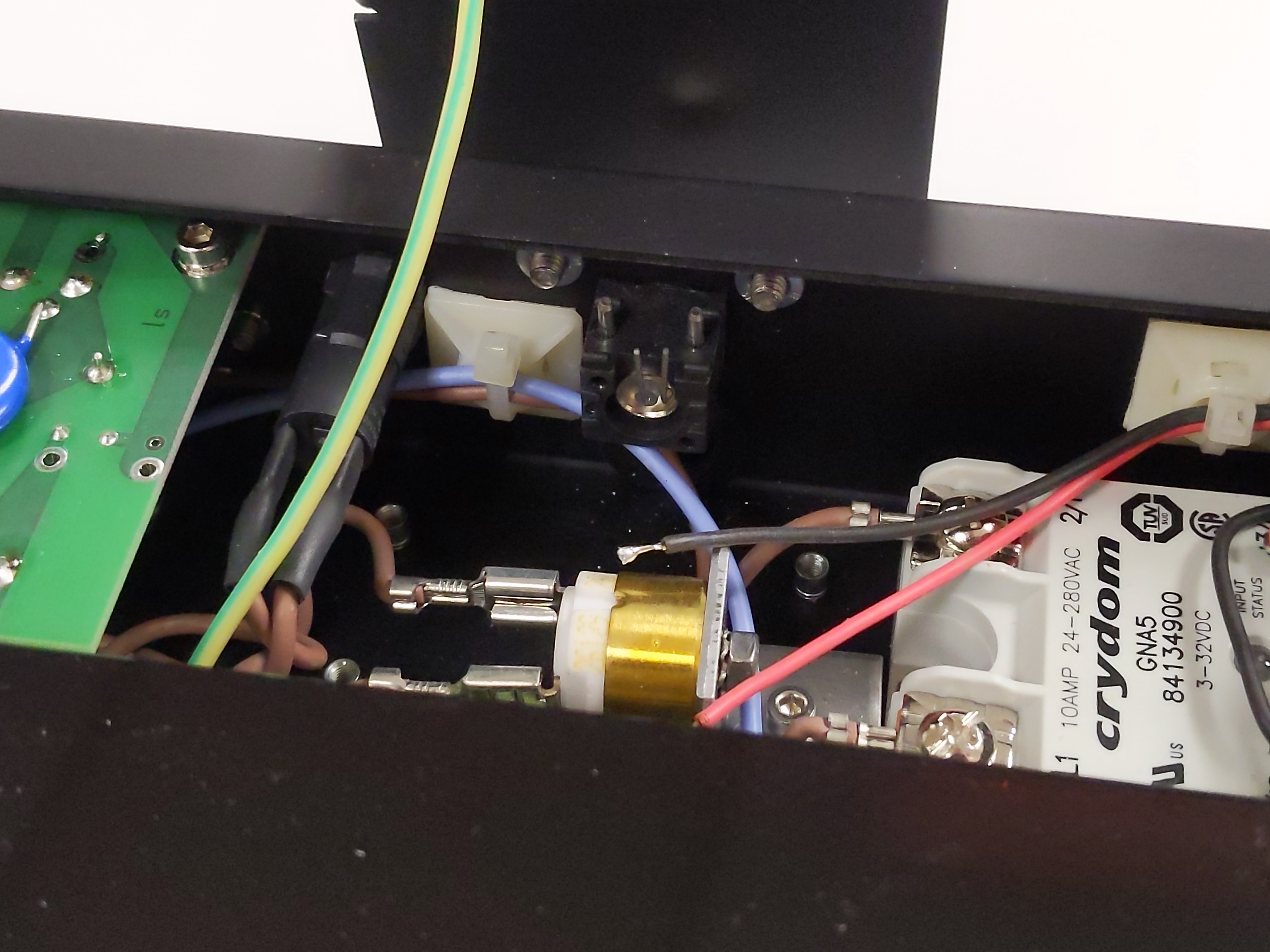
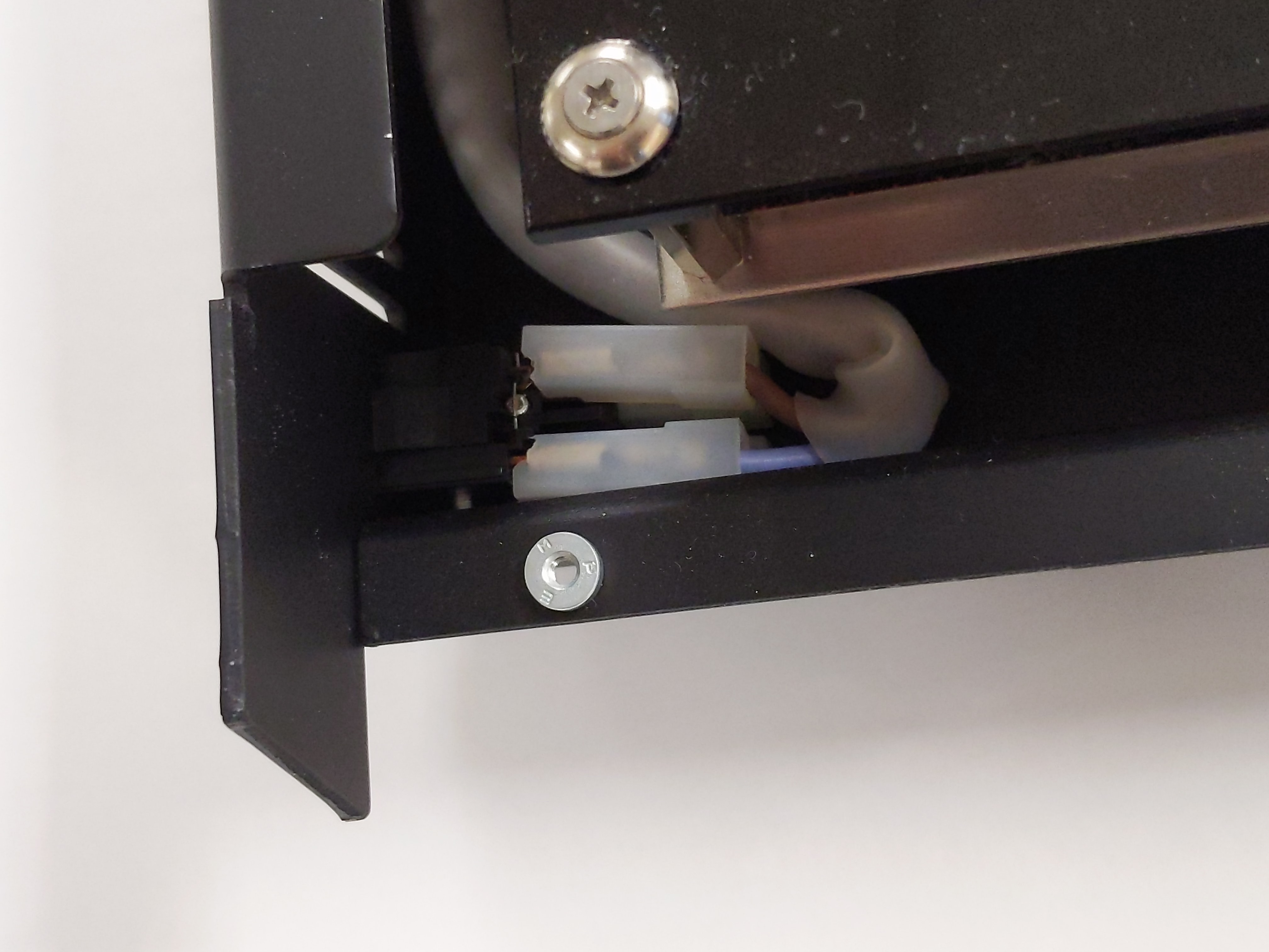
Simplified diagram of such system presented below. Current drive for the SSR input need to be provided by transistor gate or isolator. Also heater plate control input had some non-typical coaxial 3.5mm connector which I didn’t have cable for. This was easily resolved by replacing proprietary connector with simple isolated BNC port.
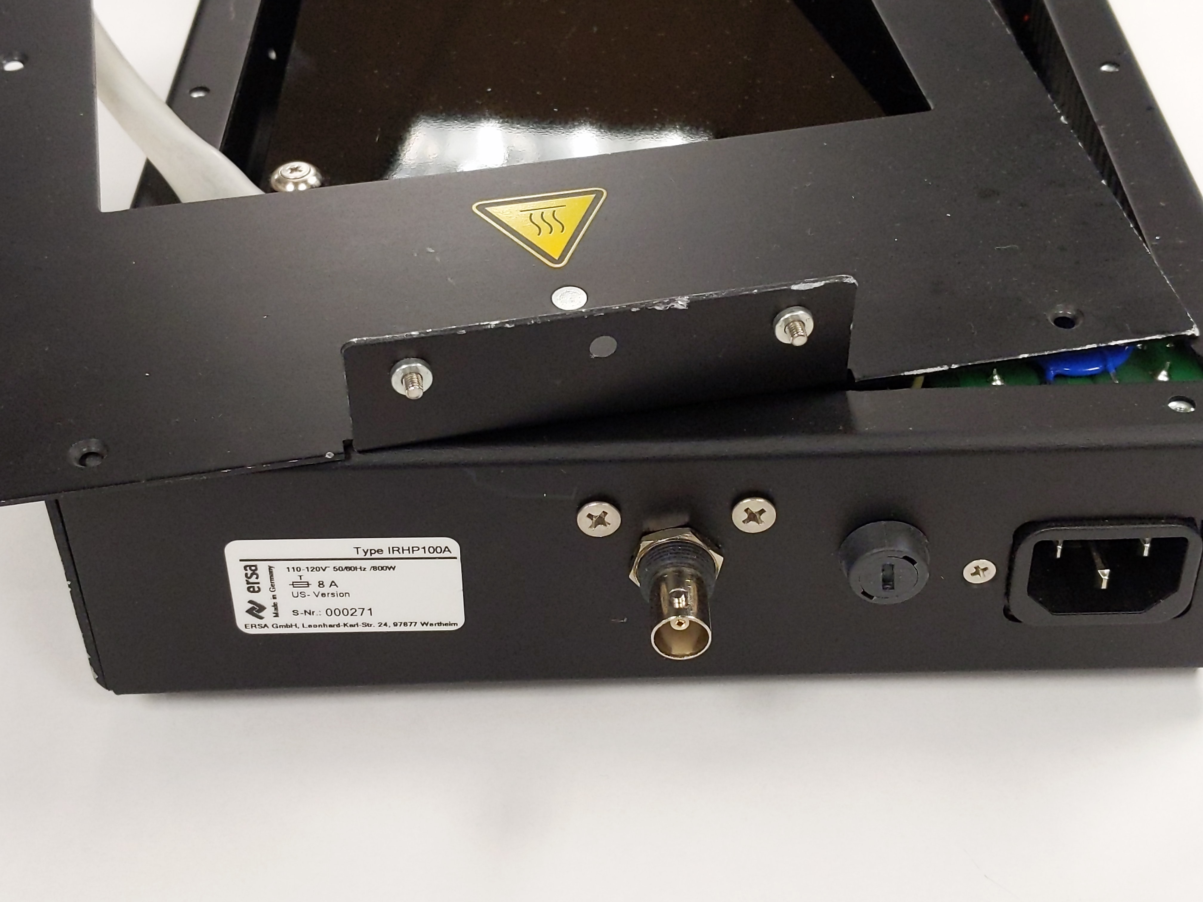
This IRHP 100A heater plate was acquired from secondary market without controller or any accessory.
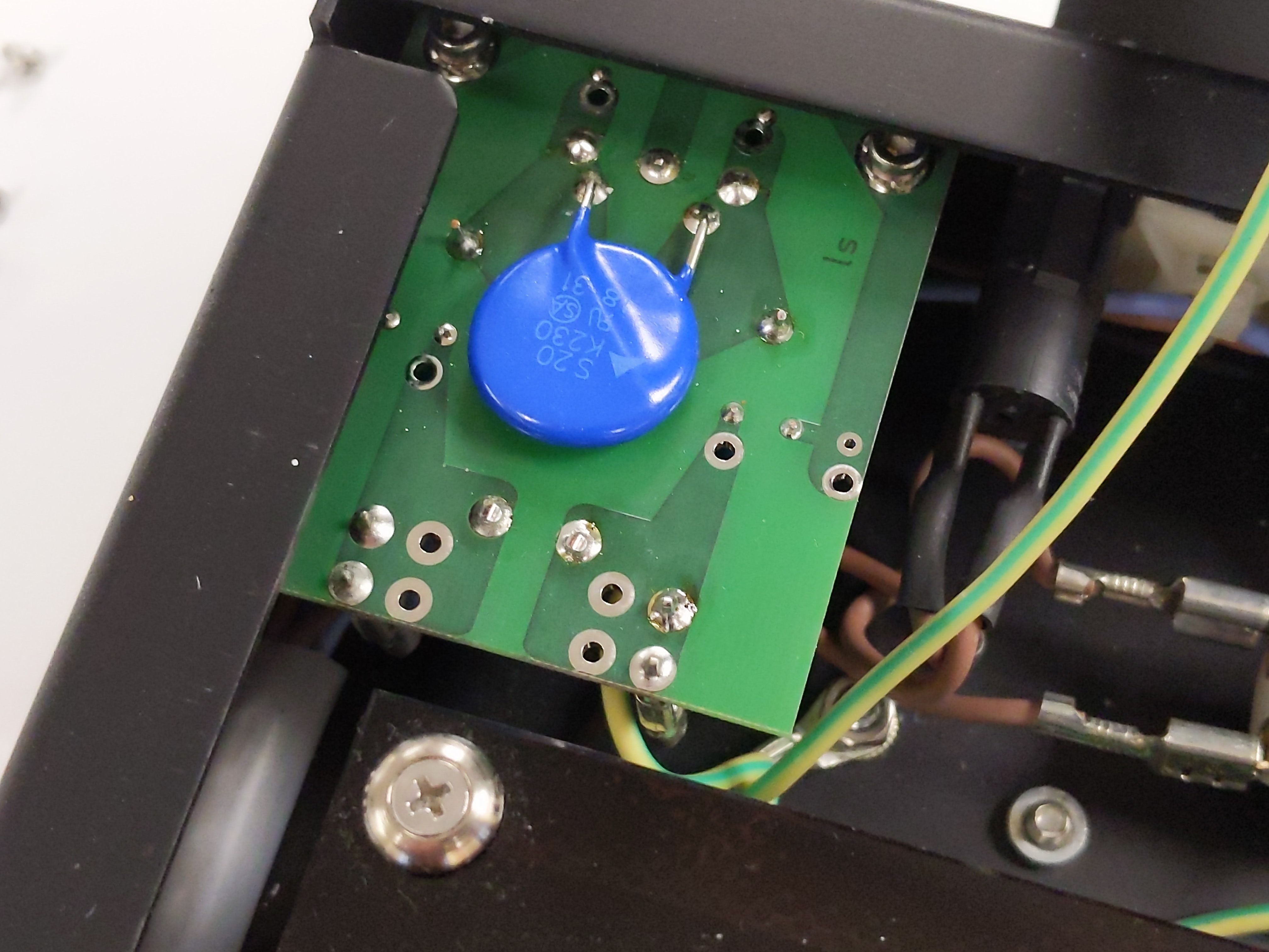
Few more photos:
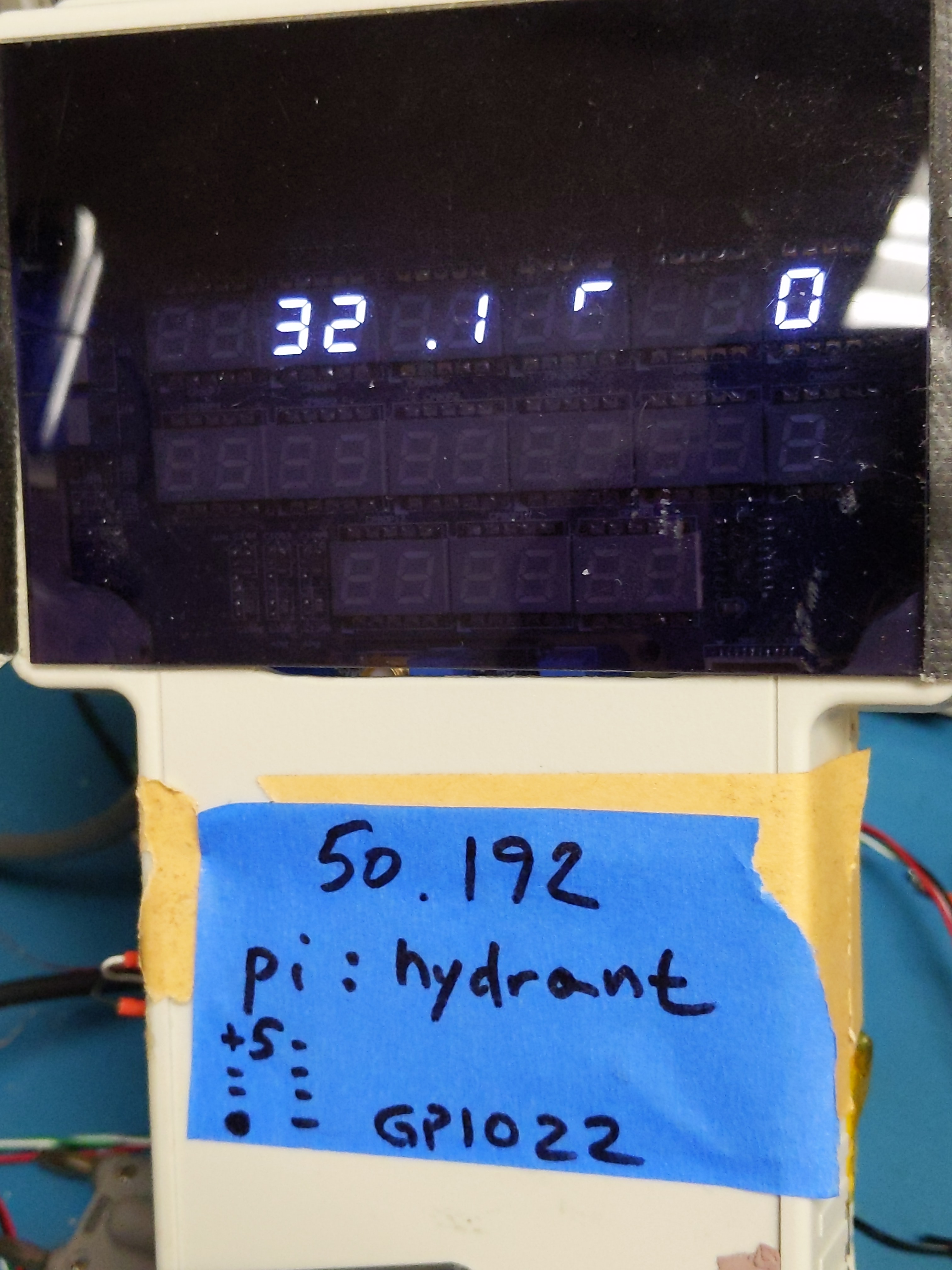
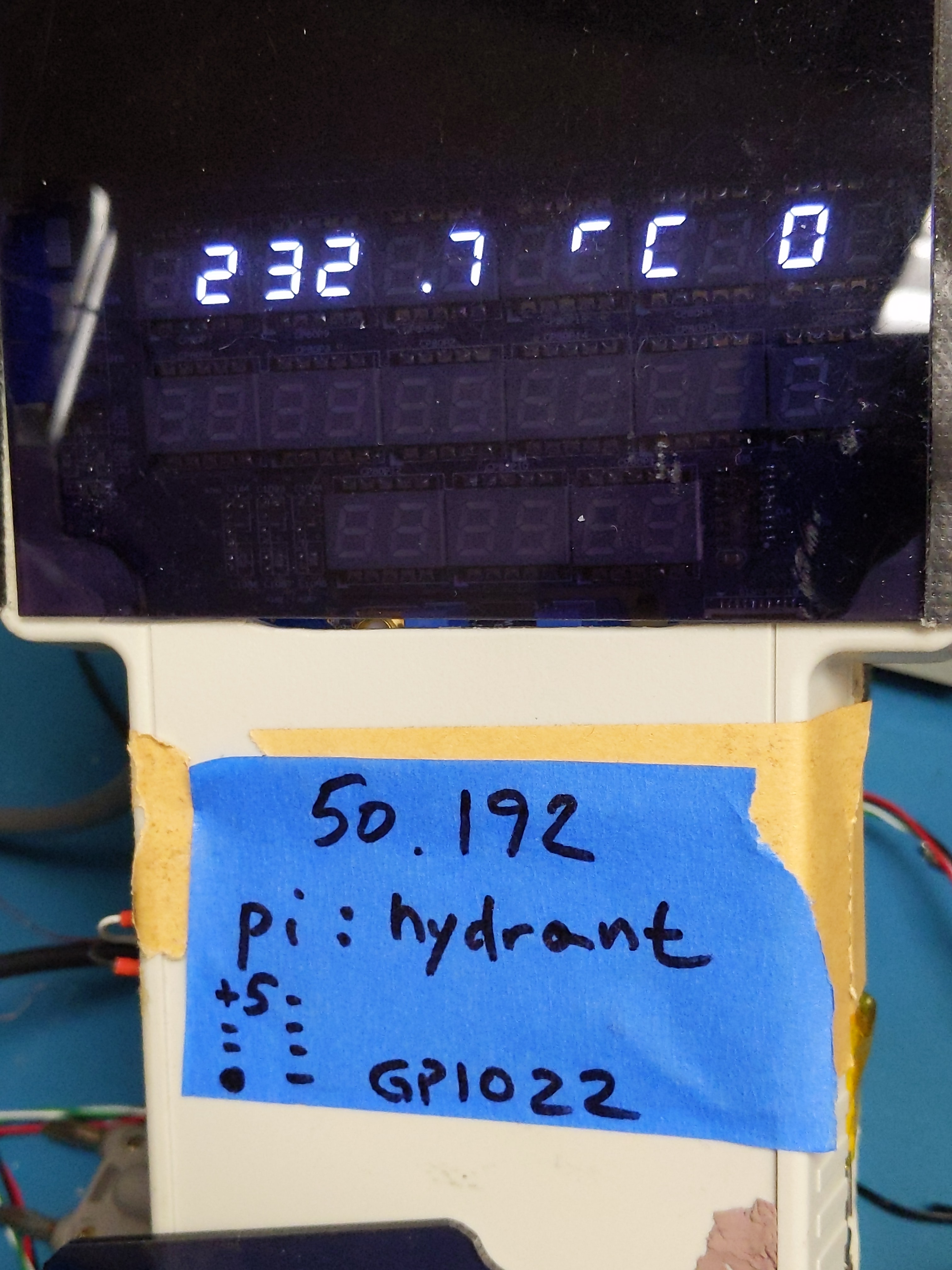
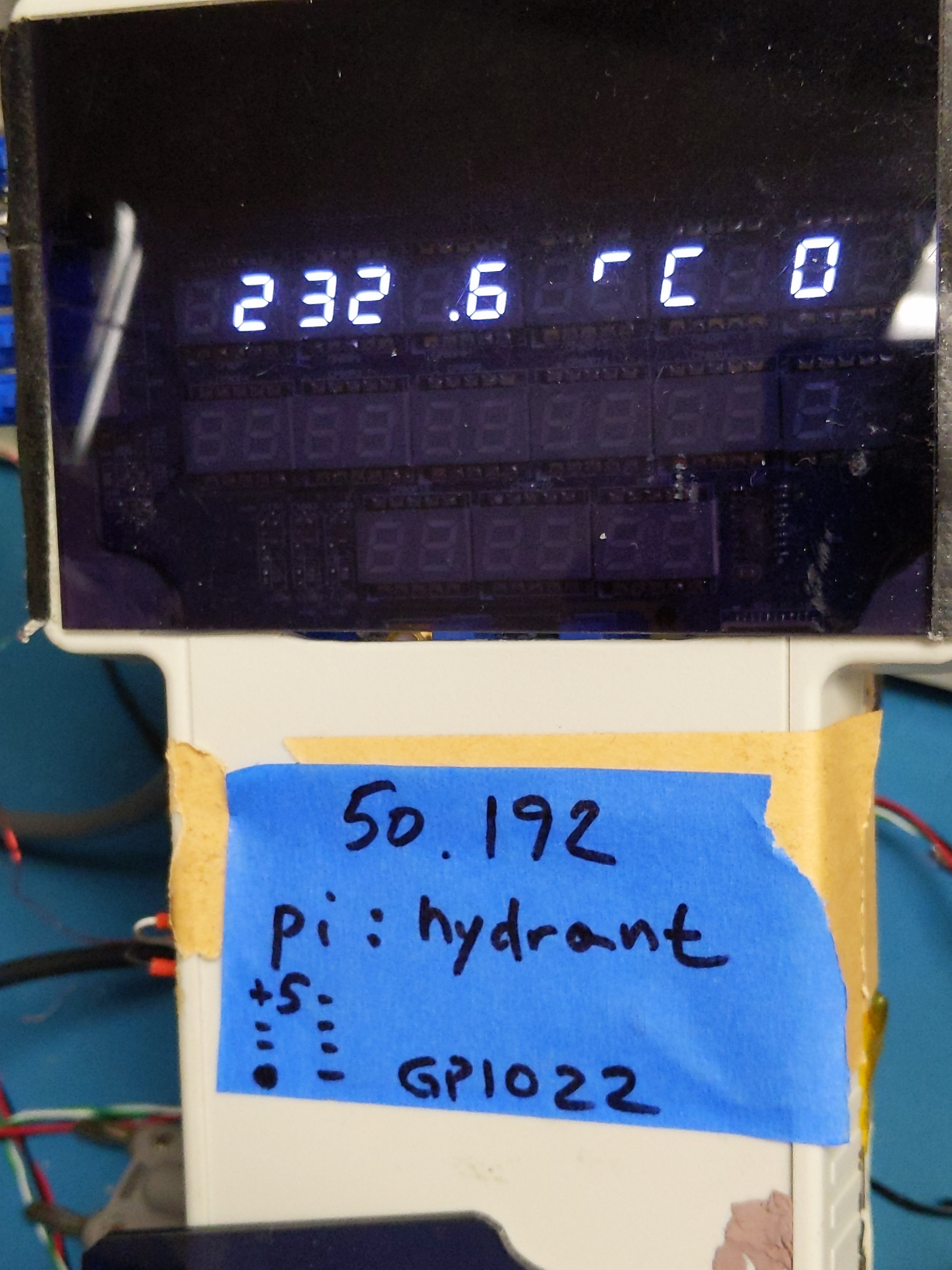
To control the station I’ve decided to reuse old project Hydrant hardware.
And on software level simple Python PID algorithm was implemented to toggle heater on or off depending on user programmed temperature readout by thermocouple.
Discussion about this article and related stuff is welcome in comment section or at our own IRC chat server: irc.xdevs.com (standard port 6010, channel: #xDevs.com).
Modified: March 8, 2024, 8:23 p.m.