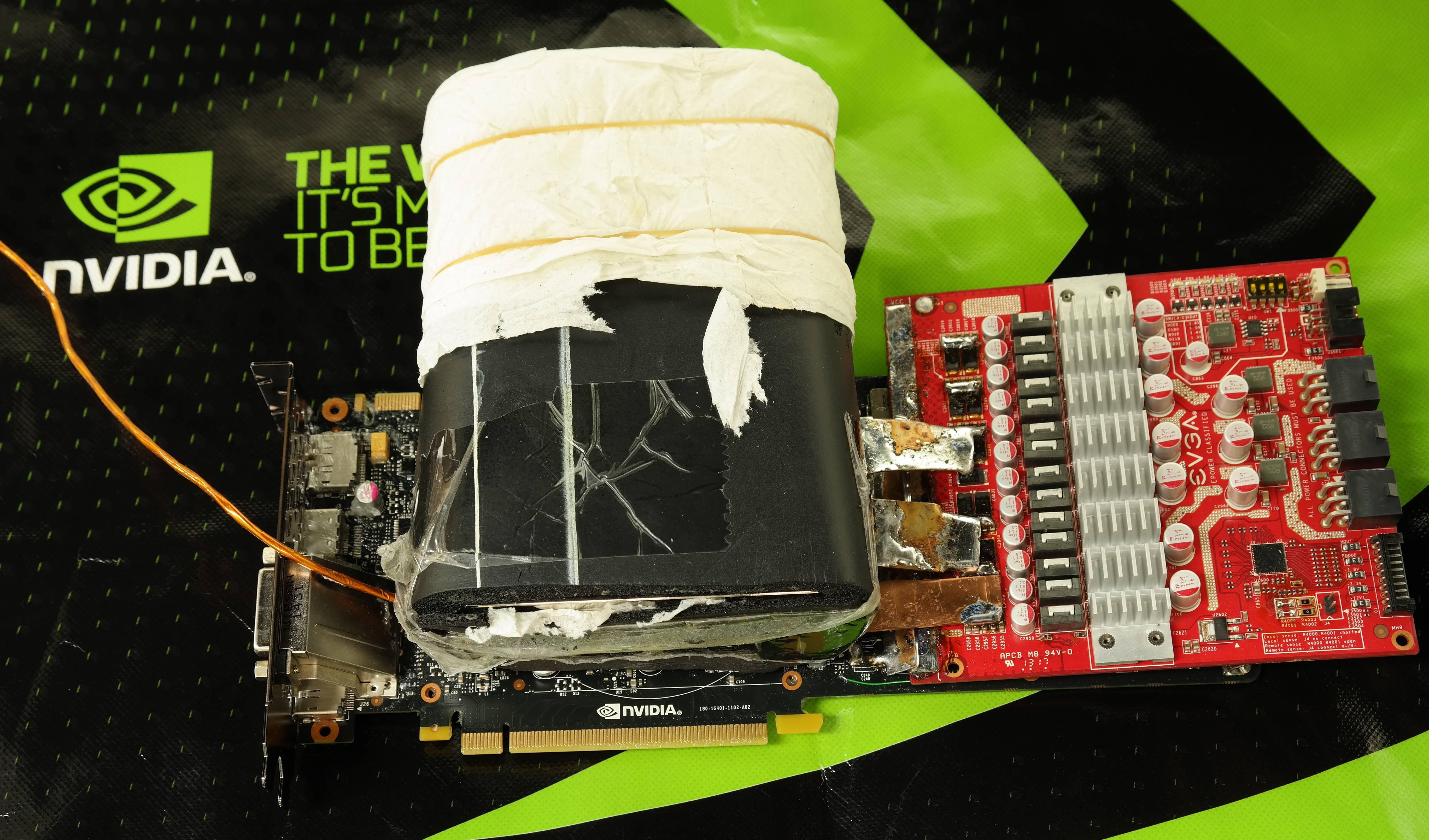
Those who followed up with us on NVIDIA GAME24 event , already know that new beast, NVIDIA Maxwell GM204 GPU is well capable of capturing some serious scores with extreme overclocking and liquid nitrogen cooling help.
We used EVGA GeForce GTX 980 reference cards together with EVGA EPOWER VRM module to reach out fearsome 2067 MHz clocks stable and clean over 3Dmark benchmarks :).
No doubt, modifying your GTX 970/980 to for these kind of results is not a five minute job and require some above-minimal soldering skill knowledge. Those heavy overclockers who are into this already got their EPOWERs, copper clads, soldering tools and Maxwell cards on operation table, but today here we talk about more broad range of pips, who just wanna max out Maxwell with simple trimpot modifications to bump voltages for everyday overclocking on air/water or even mild extreme cooling. We will also talk a little about removing power limits and overheat thermal protection.
Be very well aware, that even little simple mod, basically anything below this paragraph in this article is NOT covered by any kind of warranty, and provided AS IS, without any support from manufacturer or NVIDIA. You are on your own here, folks, so “don’t try this at home”.
Okay, enough talk, let’s blow it up! :)
STEP 1
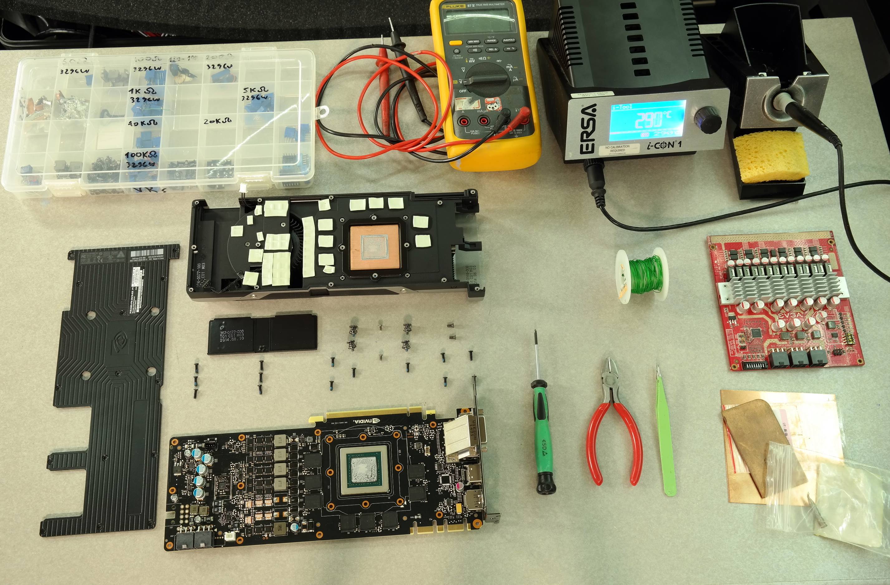
We will need basically next to get our successful modding of reference GTX 980 card.
Modification of GTX 970 follows same idea, but since layout is different, at this moment you will have
to find exact way by yourself. I’ll focus on GTX 980 first.
- Card itself. We got two EVGA GEFORCE GTX 980 (04G-P4-2978-KR) cards to play with.
- 3 × 50 ohm multiturn VRs (trim pots).
- 25-45W soldering iron for trimpot mods.
- Roll of 28-32AWG insulated wire
- Soldering FLUX
- Kingpincooling TEK9 FAT
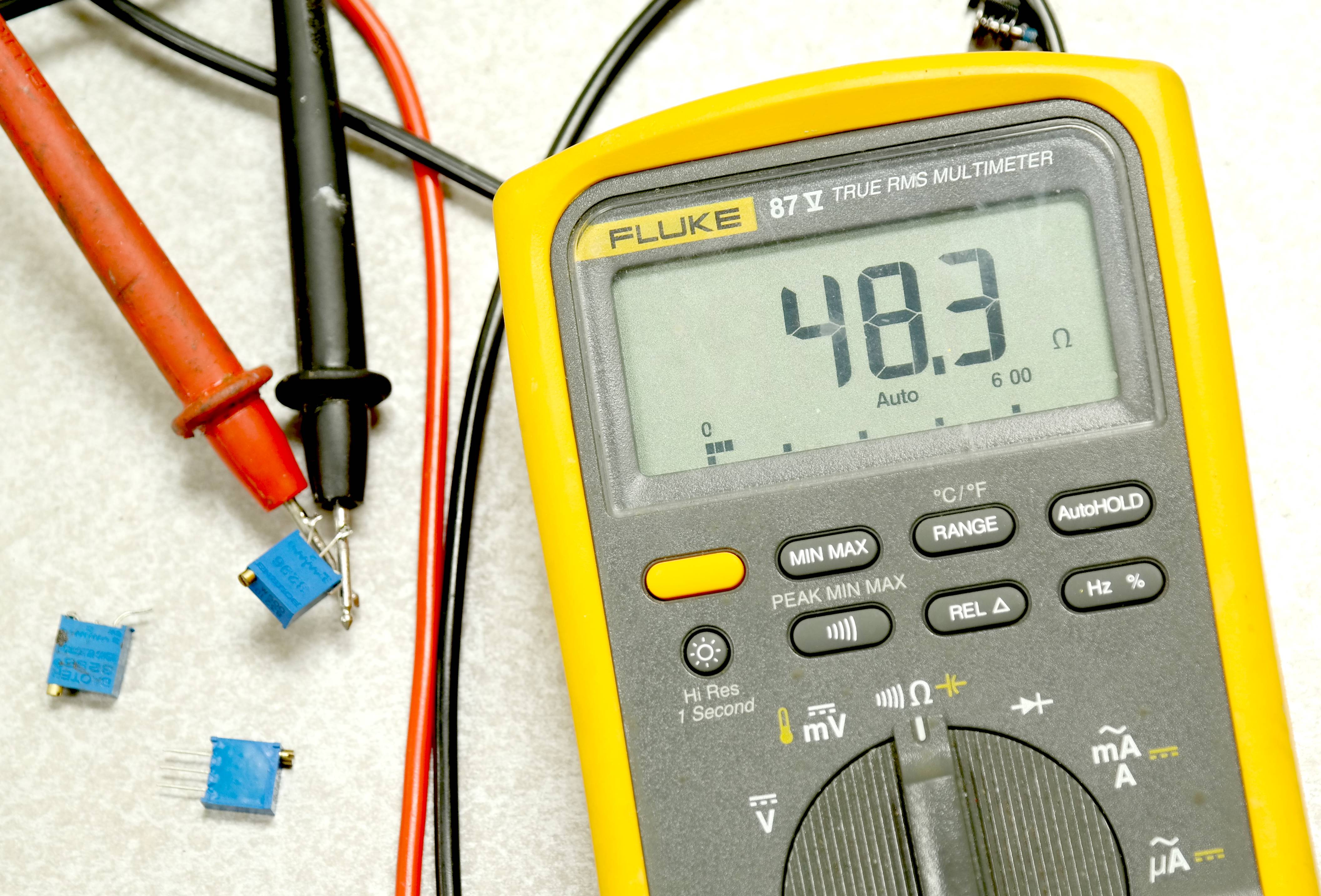
- DMM (I use my trusty Fluke 87V and Keithley 2002, but any DMM can fit this needs)
- Low-ESR capacitors (2.5 or 4V rated, 680-820uF , etc) if you like, but not required.
Since we don’t cover EPOWER connection to card this time, we don’t need to use high-power soldering iron,
so pretty much any soldering gear you have on table will fit the task.
I got an upgrade for my personal gear setup, so from now soldering with ERSA iCON-1 soldering station with 120W capable soldering. I used 102CDLF2.4 tip for this guide, temperature set to 290C.
Clean your mess on table, get all tools checked and ready, turn on enough lights to clearly see tiny parts on PCB. Your setup should look like next:
STEP 2.
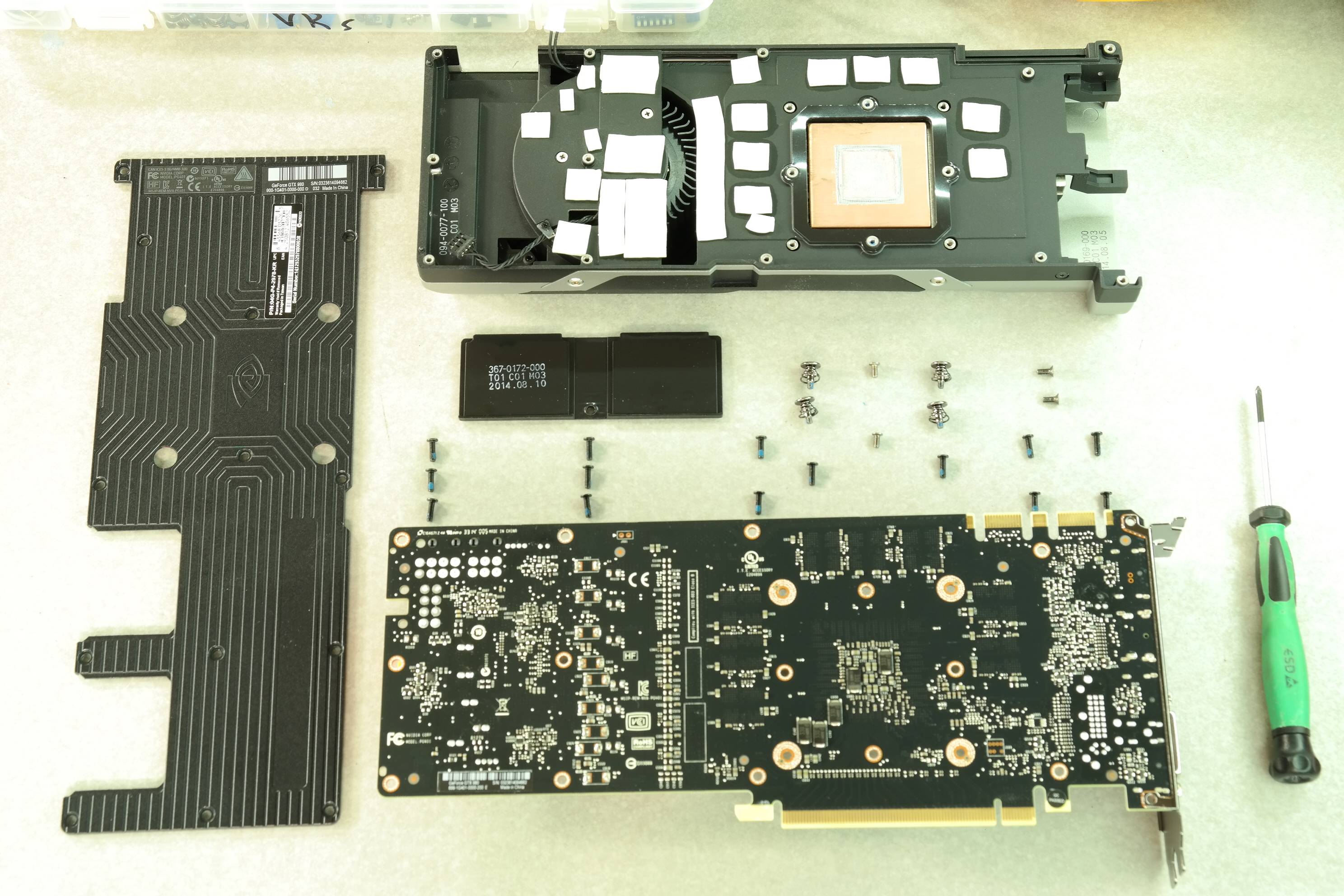
Remove cooler from the card, since we need access to front of PCB.
This time NVIDIA did not use TORX, so usual philips will do just fine. Better keep all those custom screws
in secure place together, so you can put heatsink back after you done if you will decide to do so.
Remember, after soldering your warranty will be surely violated, as every RMA center will easily see non-factory soldering specks, even if you very careful ;)
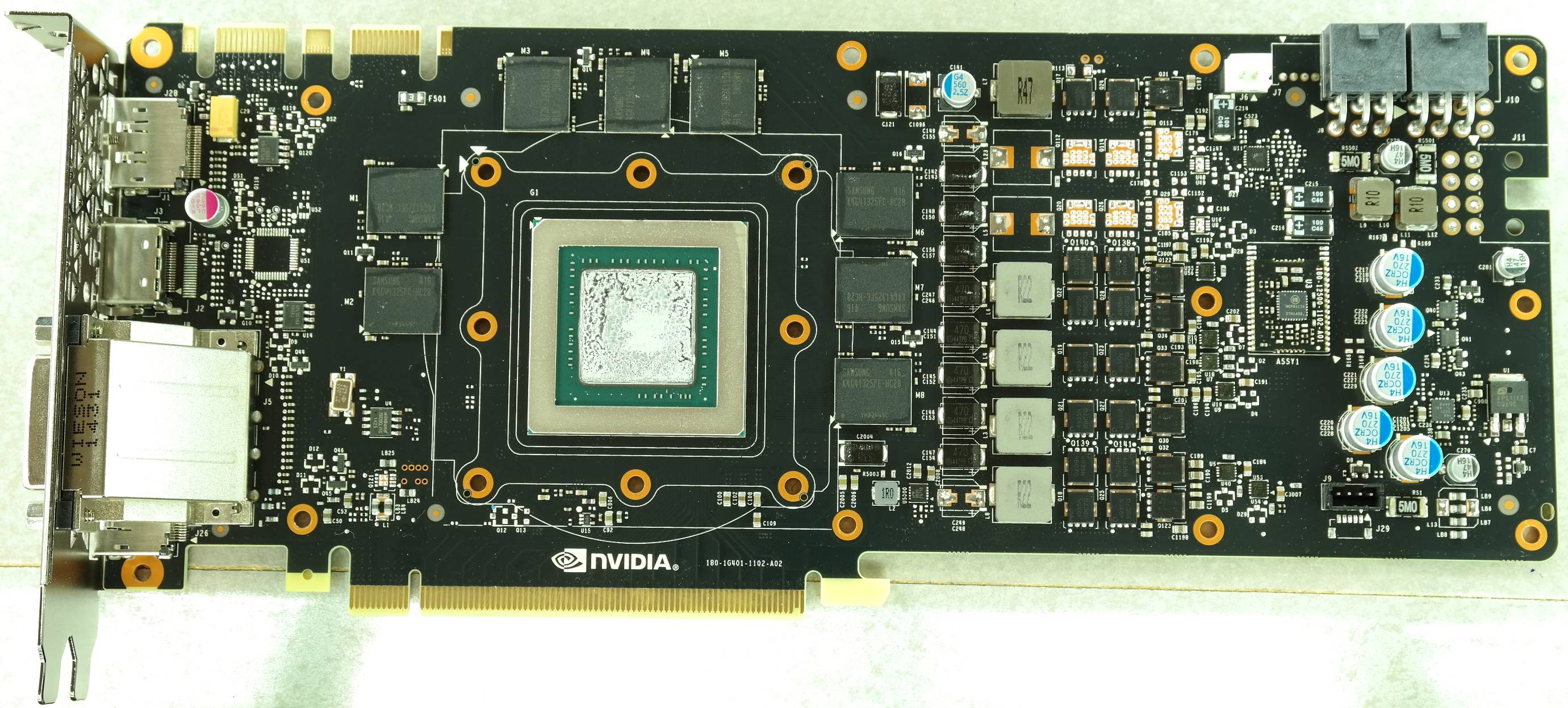
Our table now looks like this:
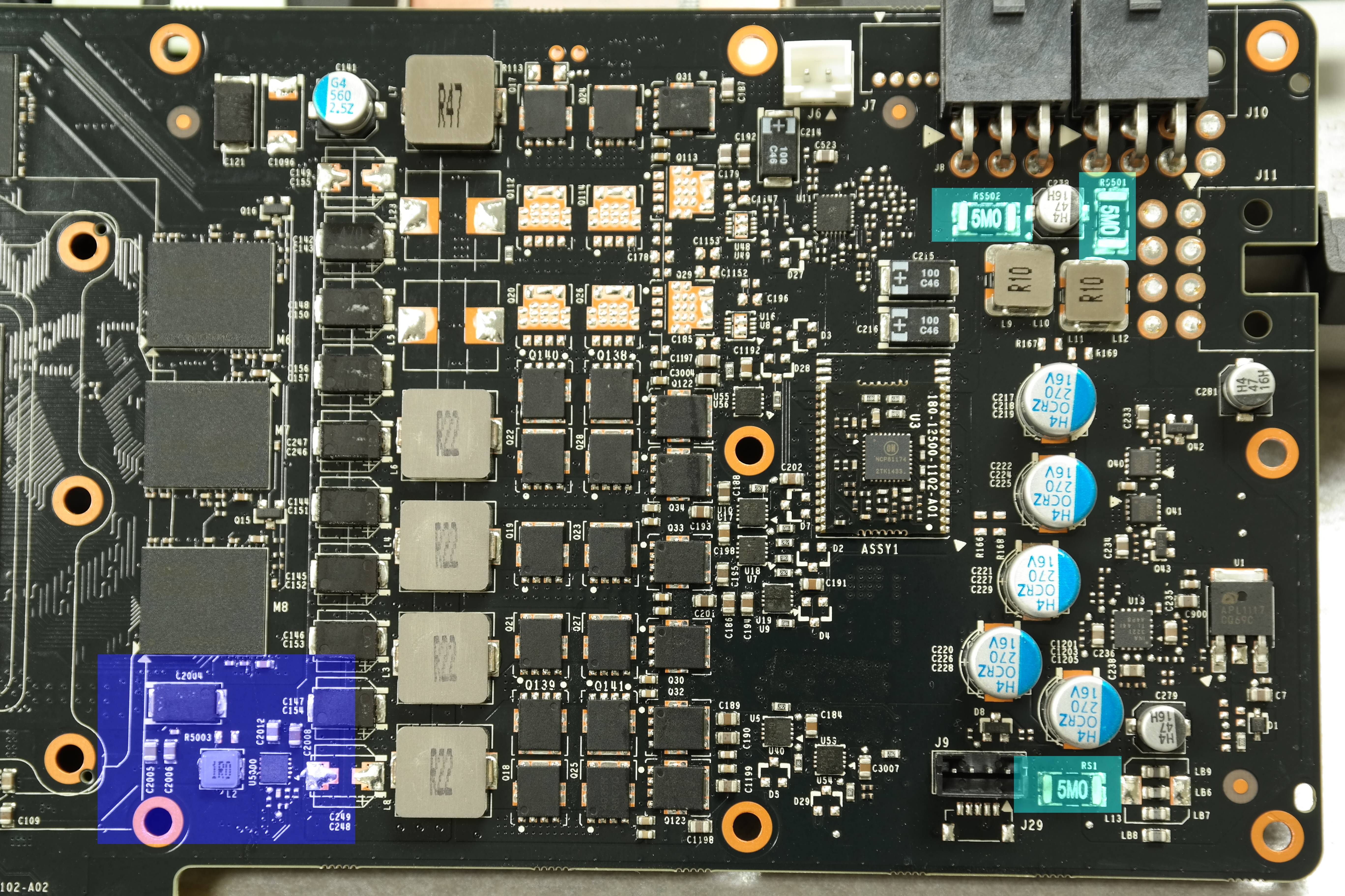
Primary areas to see are: Green – GPU voltage controller, Red – memory voltage controller area:
STEP 3.
Prepare VR’s. Find 50 ohm nominal resistance multiturn variable resistors (potentiometers). I use very common blue square 3296 type.
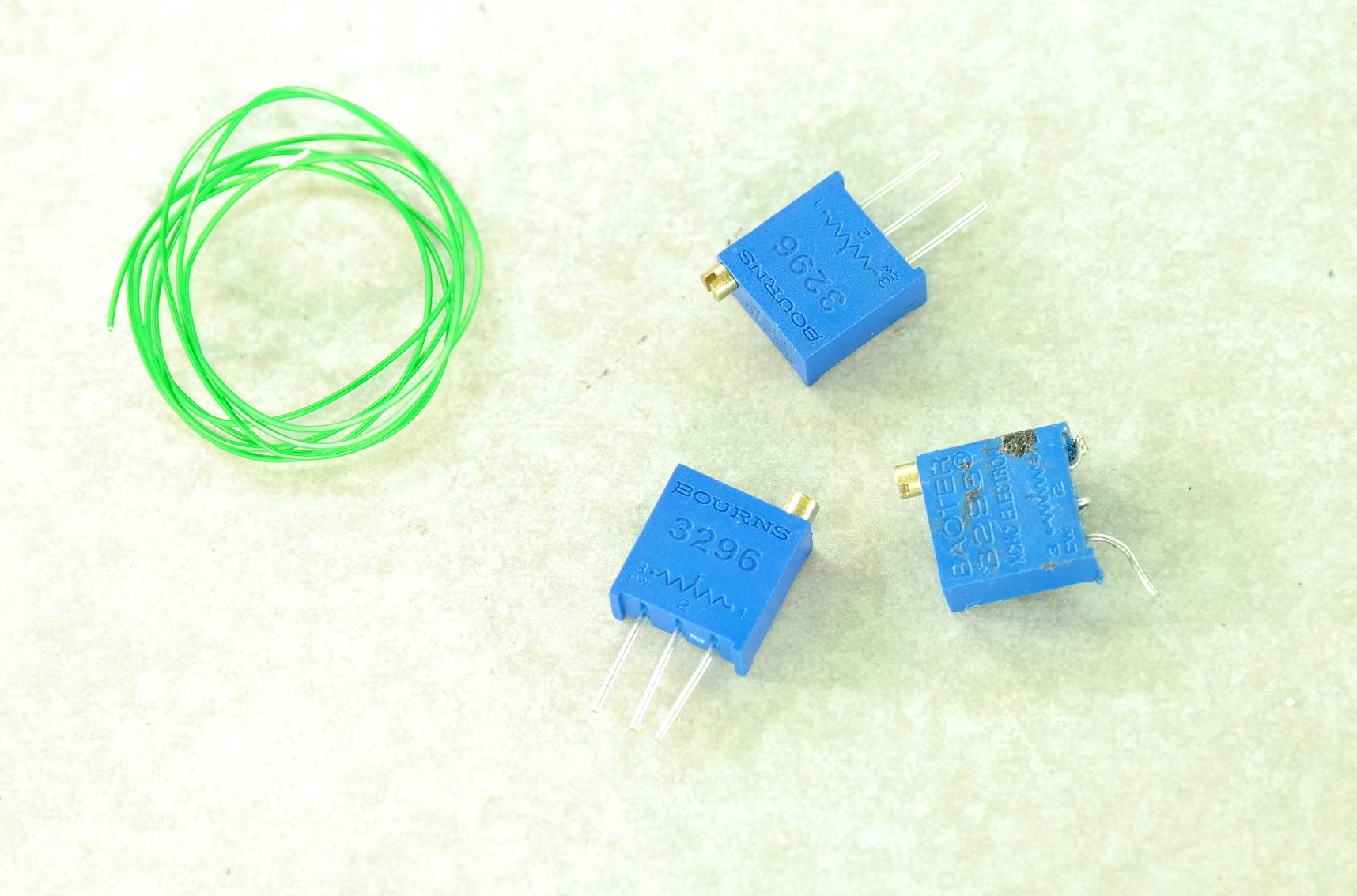
Use your DMM to turn pot all way to the max, so you will start from lowest bump on voltage after card is powered on. We will add them to adjust three main rails present on card:
STEP 4.
NVVDD trim-pot mod
Need to remove two resistors marked on photo below to enable adjustment on feedback sense.
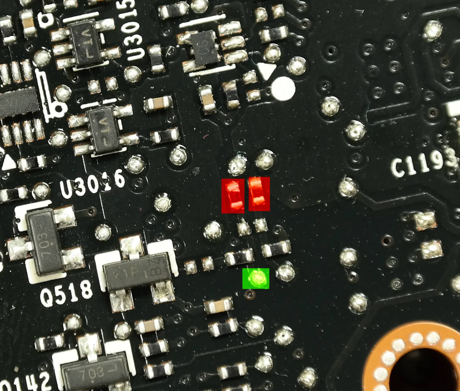
Now add 50 ohm trimmer to point as shown on photo below. Solder middle terminal of trimmer to marked point with thin AWG28-32 wire.
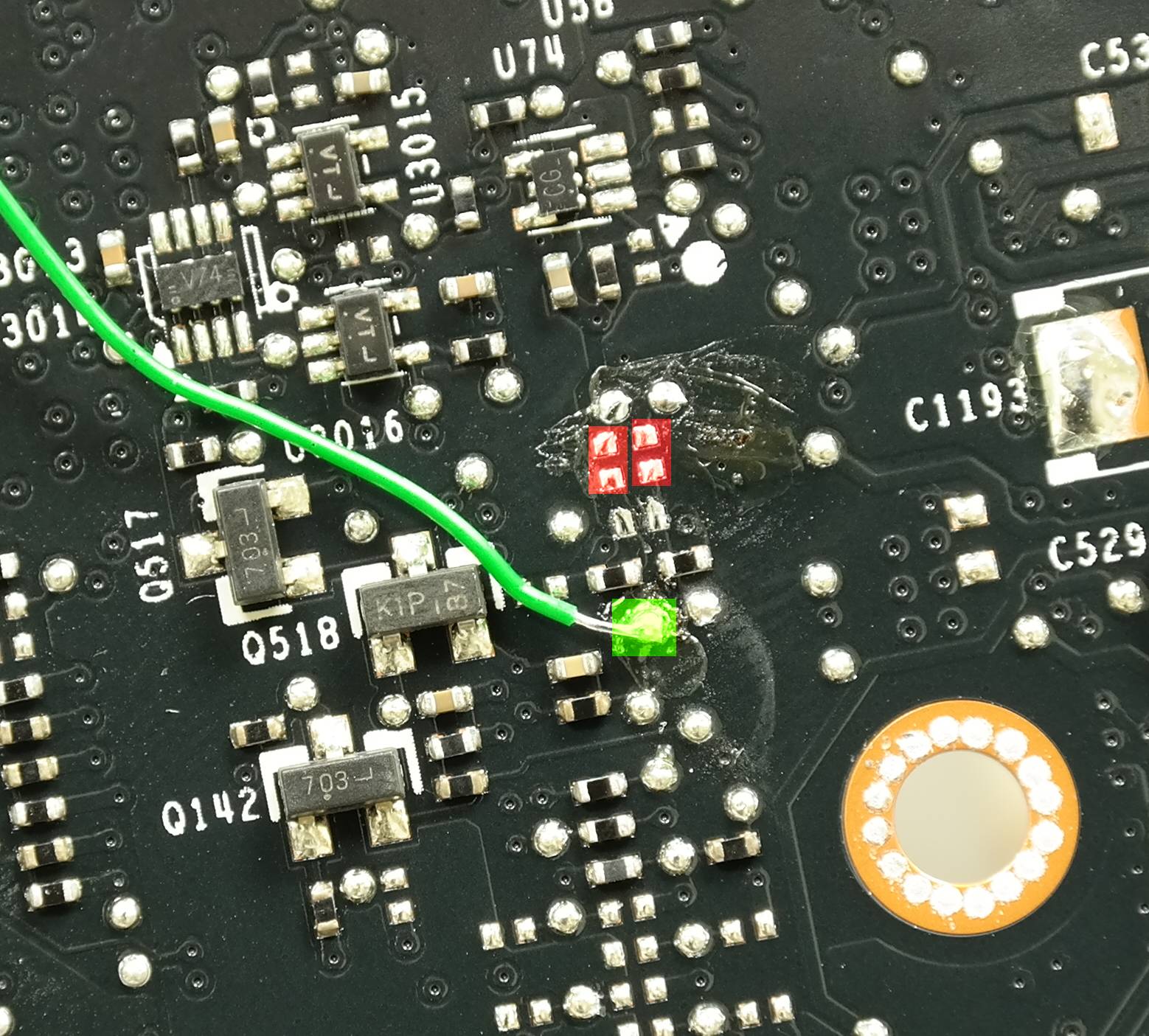
Solder second terminal of trimpot to ground nearby (you can use mounting hole for that, they all grounded as well).
You can go as high as 1.7-1.85V with this kind of modification, so it’s suitable for extreme overclocking.
But beware, safe voltages even on LN2 are rather around 1.5-1.6ish range, which is still enough to get decent overclocking on most of the cards. 1700-1800MHz clockspeeds should not be an issue.
Resistance at marked point on non-modded card is about 90-110 ohm with resistors removed, and about 4-8 ohm with resistors present.
STEP 5.
FBVDD (memory) trim-pot mod

Add 50 ohm trimmer to point as shown on photo below. Solder middle terminal of trimmer to marked point with thin AWG28-32 wire.
Solder second terminal of trimpot to ground nearby (you can use mounting hole for that, they all grounded as well).
Resistance at marked point on non-modded card is about 25-30 ohm.
STEP 6.
PEXVDD (PLL) trim-pot mod
PLL controller located near memory chips and PCIe edge connector.
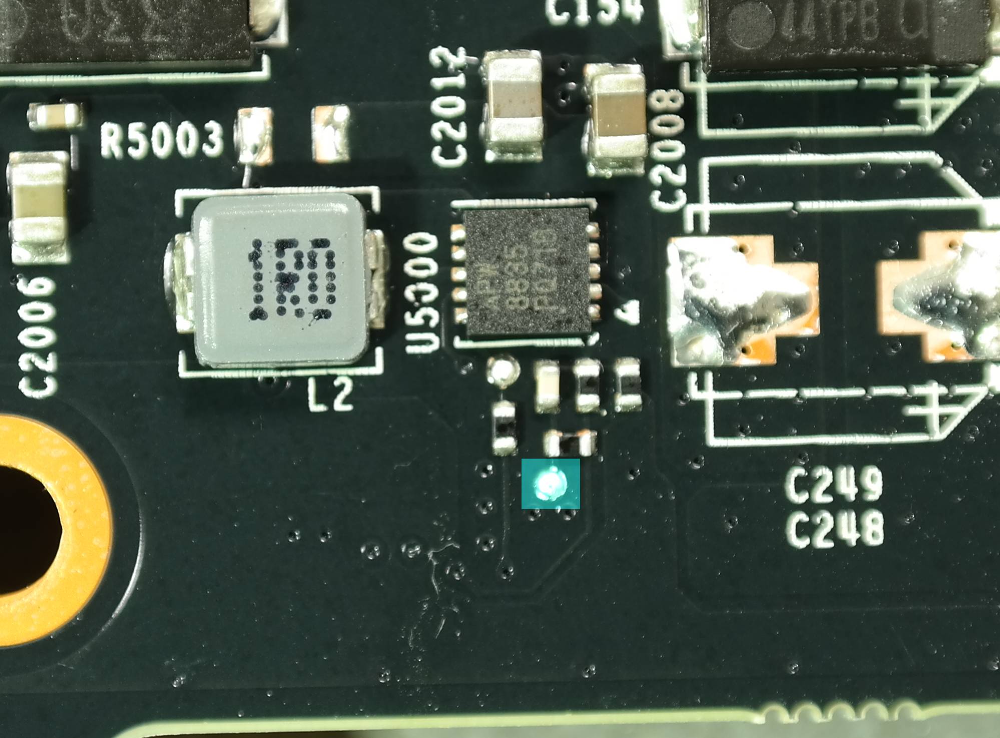
Add 50 ohm trimmer to point as shown on photo below. Solder middle terminal of trimmer to marked point with thin AWG28-32 wire.
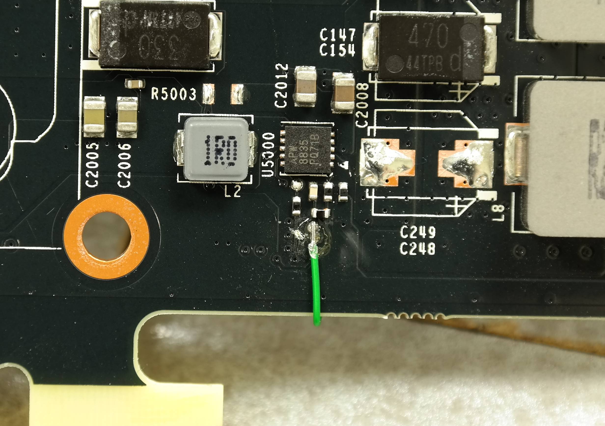
Solder second terminal of trimpot to ground nearby (you can use mounting hole for that, they all grounded as well).
Resistance at marked point on non-modded card is about 170-180 ohm.
STEP 7.
Check all resistances, and make sure everything is correct. All trimmer points must not be below 1 ohm, or you will get too high voltage on your rail, which can damage card very quick.

You can find grounds with your DMM by checking resistance. If you see less than 0.5 ohms (absolute) resistance between mount hole and your point – pretty sure it’s ground.
STEP 8.
Now we can remove power limit via hardware mod.
Guides before shown to add 5 ohm resistor on sense network, but it’s actually easier just short a shunt, as ones used on GTX 980 reference cards are big and easy to solder on top of them. So just short three shunts with piece of copper or solder blob, and you good to go, now your power limits will never be an issue on any clocks or voltages.
I’ll just show you shunt resistors locations here:
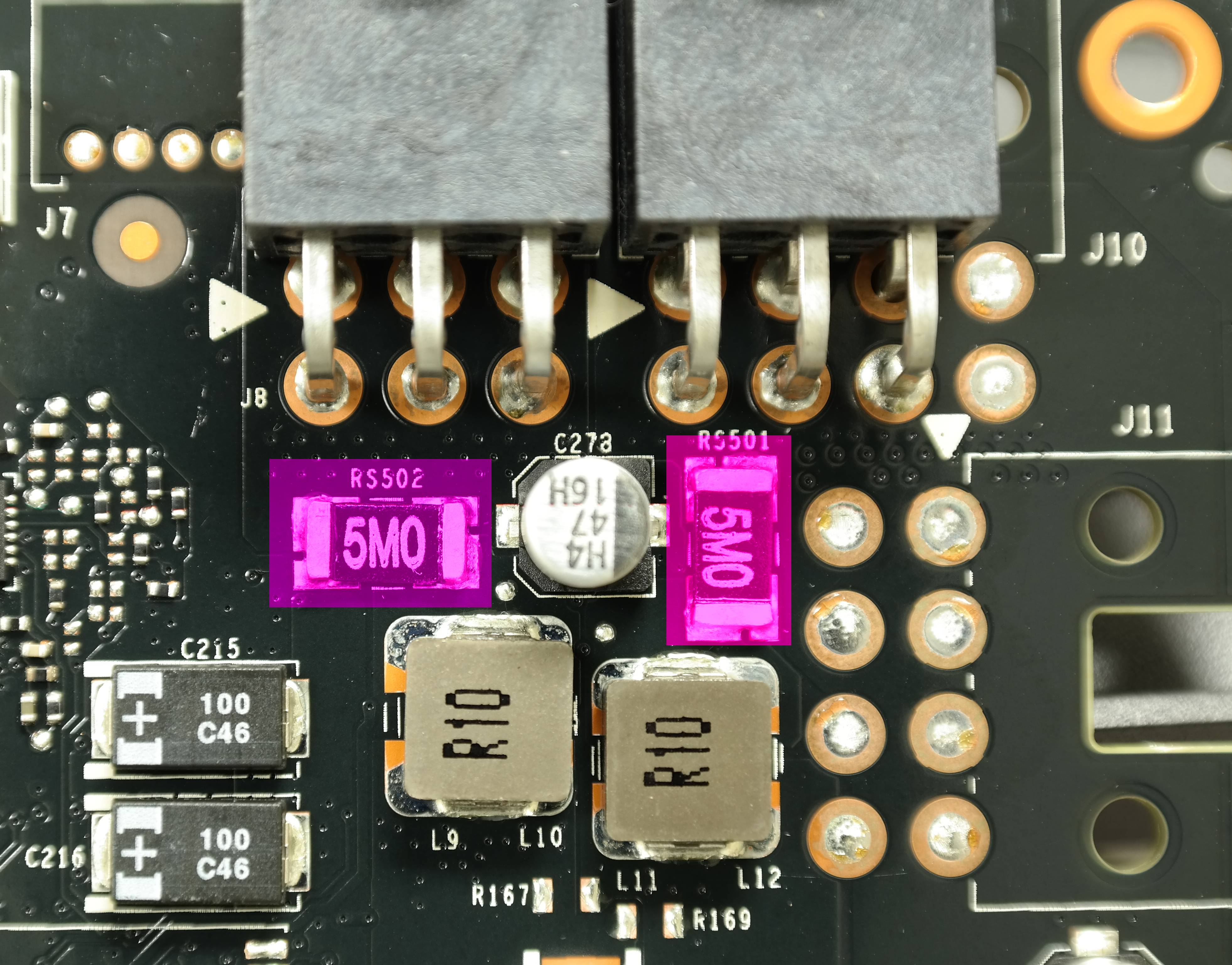
There is one 5M0 shunt (0.005 ohms, or 5 milliohms) below, but that one just from PCIe +12V rail for memory, you can leave it stock, or short it, both will do fine even for LN2 sessions, and will get you below 100% of your power limit in stock VBIOS. No, I don’t have any VBIOSes for GTX 980, no need to ask.
STEP 9.
Check again, if everything good, no shorts on the card or damaged parts, solder blobs or dirt. Make sure all trimpots are set to proper value.
Assemble your cooling solution to a card, test voltages and give it a spin on overclocking, using EVGA Precision X 16.
STEP Bonus.
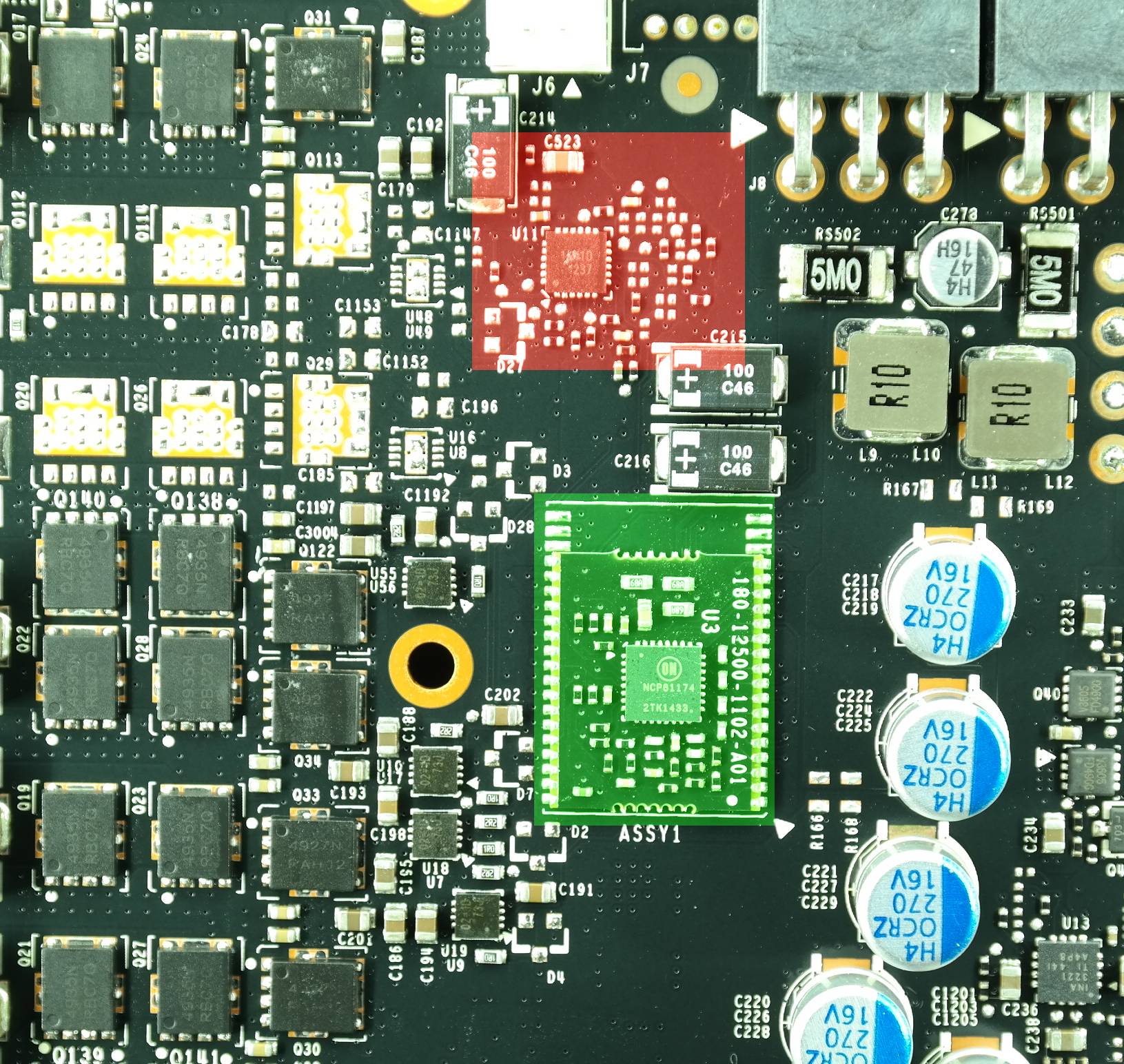
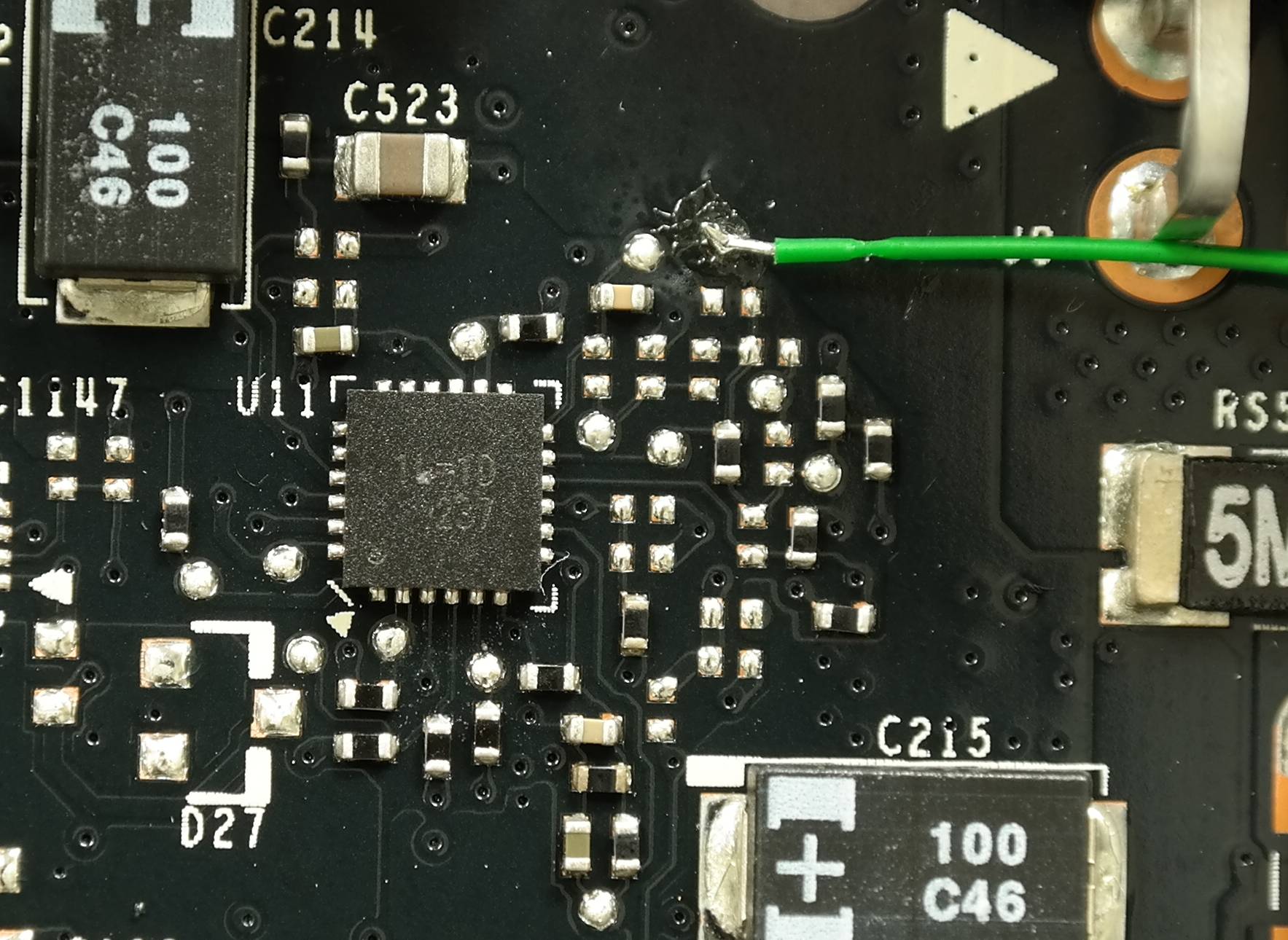
For die-hard EPOWER guys, like our friend in Brazil, here’s magic sauce to enable EPOWER function on this cards:
Locate VRM module with ONsemi NCP81174 chip, located on little board soldered to GTX 980 PCB.
Cut two traces marked red on photo below. Make sure not to cut anything else :D.

Now you can solder your EPOWER to GTX 980, and it will work just fine, exactly like it was on GTX680, GTX780, Titan, GTX780Ti, GTX770 and so on.
Have fun, and don’t forget to post scores and push for records.
P.S. Apologize for bad photos, was not in the homelab while making this guide.
Modified: Jan. 20, 2022, 5:56 p.m.