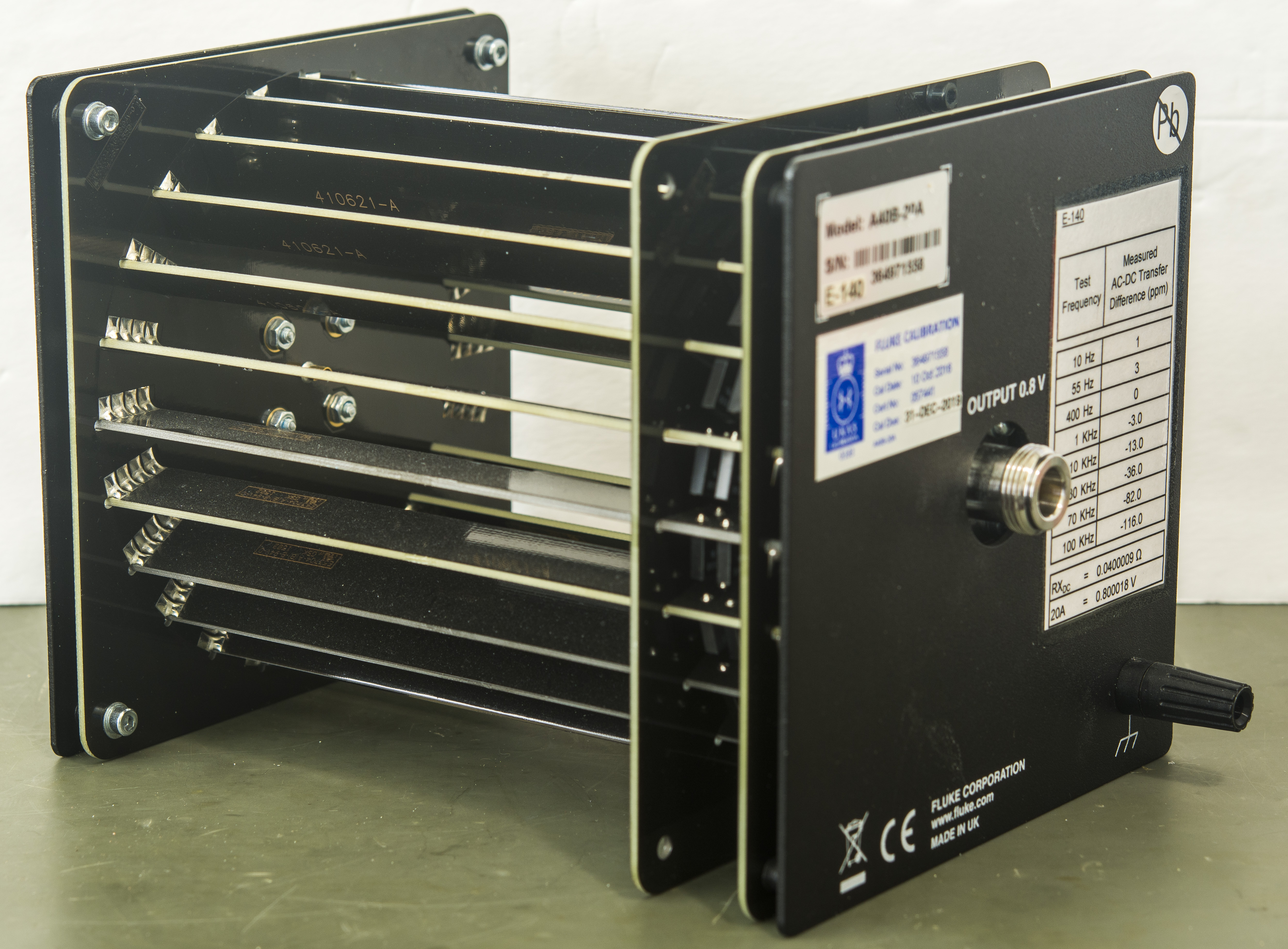
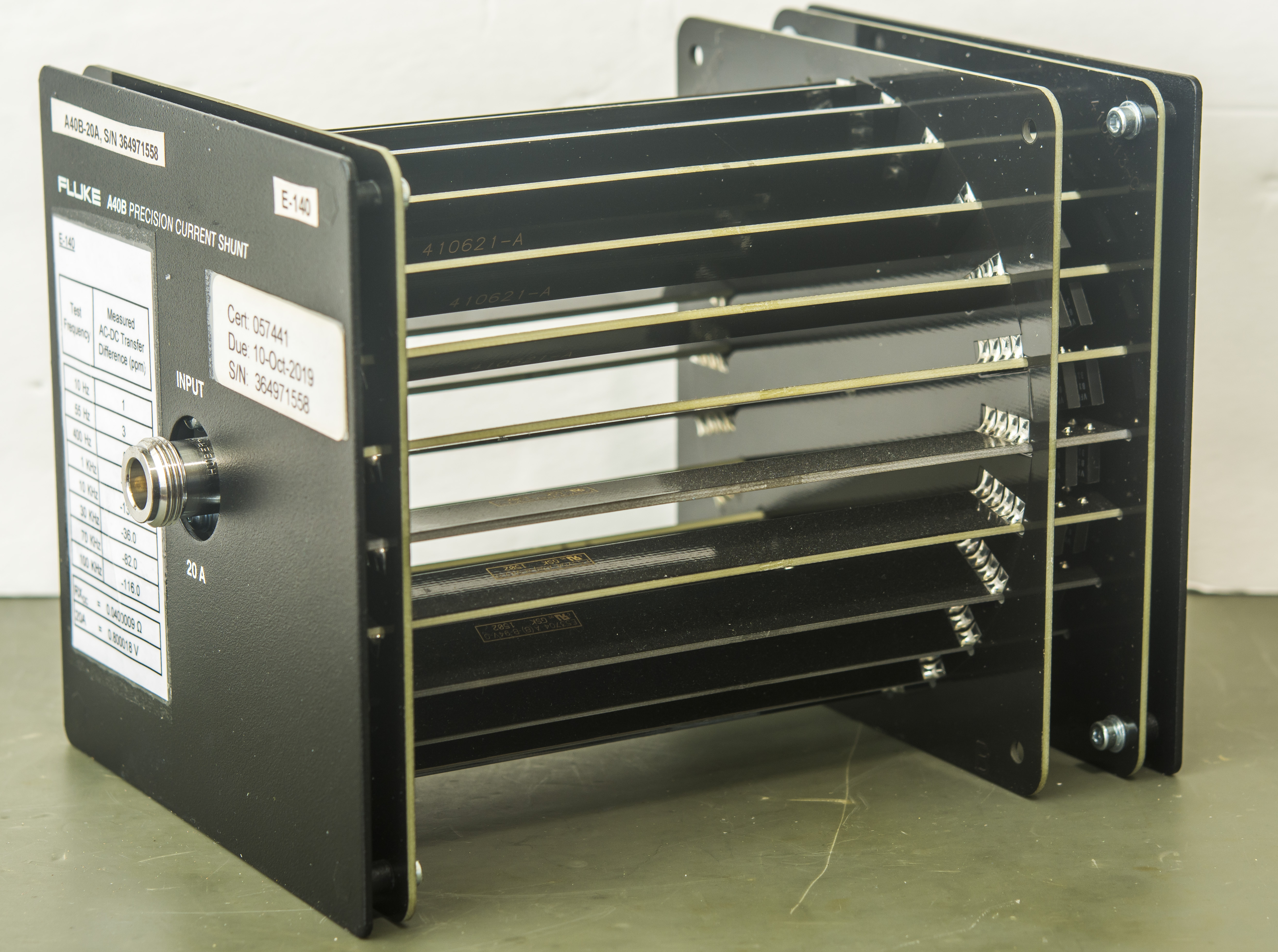
Initial failure
While testing Fluke A40B 20A shunt at half-power I needed 10A AC current source. For this high-end calibrator system with Fluke 5720A and Fluke 5725A amplifier was used. It worked fine for over a week testing Wavetek 4953 10A AC/DC shunt previously but actually developed a fault in a first day with A40B.
5725A had tripped output while switching between and sourcing +10 A DC, -10 A DC and 10 A AC current with frequency 40 Hz. Previous test steps with 30 Hz, 20 Hz and 10 Hz were recorded and measured currently. This can be observed on this datapage.
Upon verification 5725A was having a problem with fault “5725 Current Drive Path Open, error 3212”. This means something went terribly wrong with current output stage, responsible for 11A range. So time to take it apart and check what’s wrong. 5725A shows same fault with both primary 5720A and backup 5720A calibrators
The voltage output transistor heat sinks are at lethal voltage potential in ac v standby and ac v operate modes during normal operation, and possibly in any other mode after a failure. The heat sinks are exposed when any assembly is in the service position, and when the heat sink cover is removed. Use only non-conductive tools, and keep one hand behind your back to avoid making a circuit through your body. If you work on a 5725A with the power cord attached, and/or you are not certain the high voltage has not bled off, do not wear a grounded wrist strap. Wearing a strap increases risk of dangerous electrical shock.
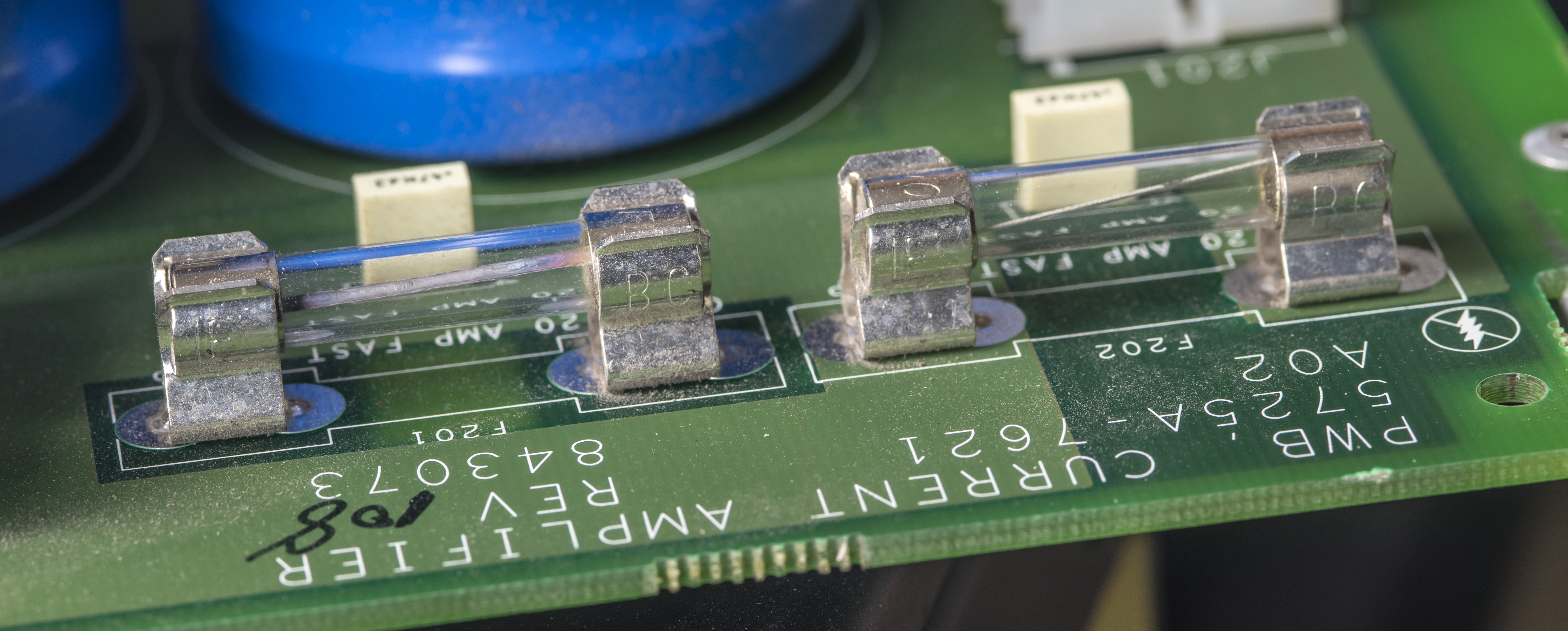
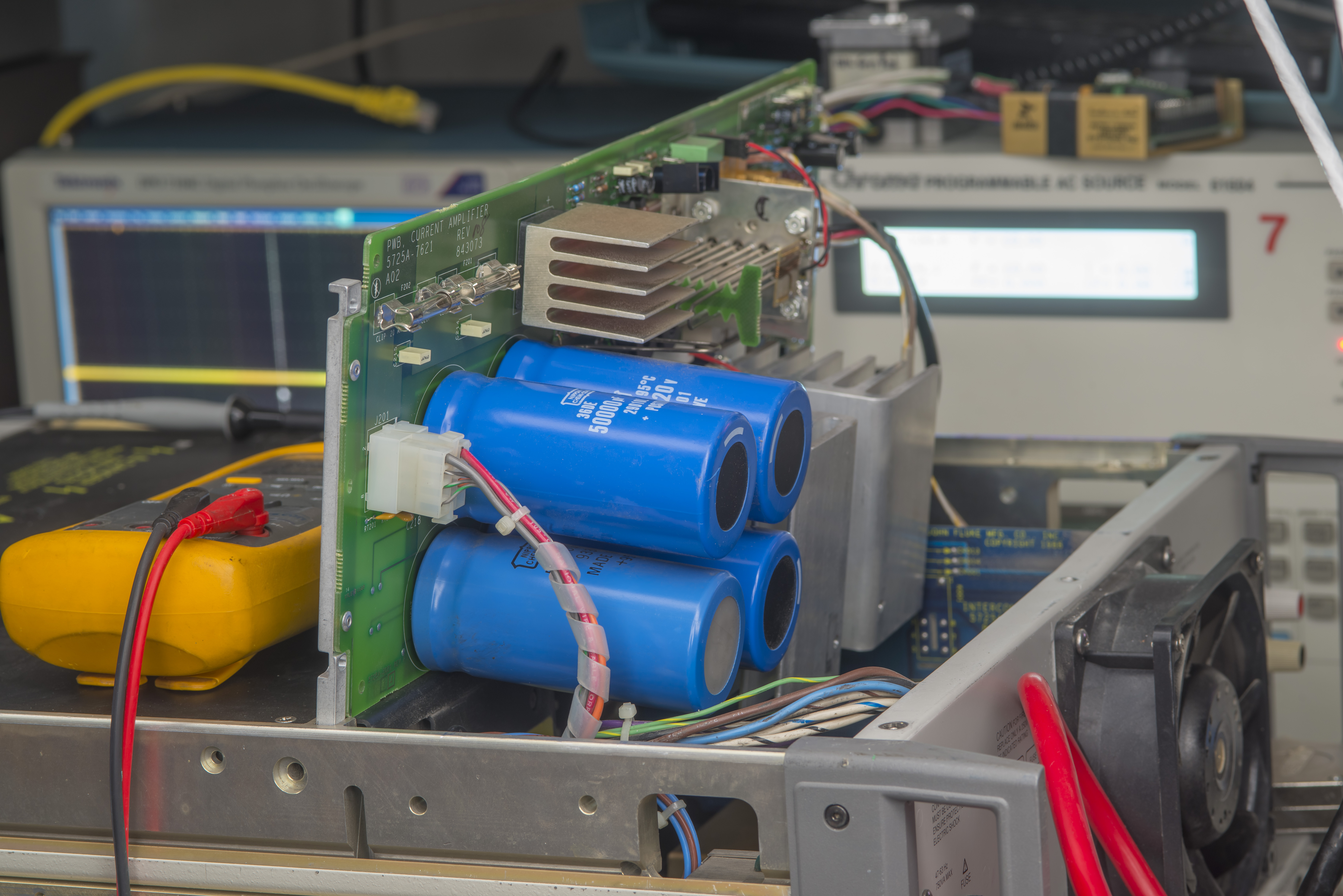
Quick teardown and quick look on A2 high current PCBA revealed at least obvious fault:
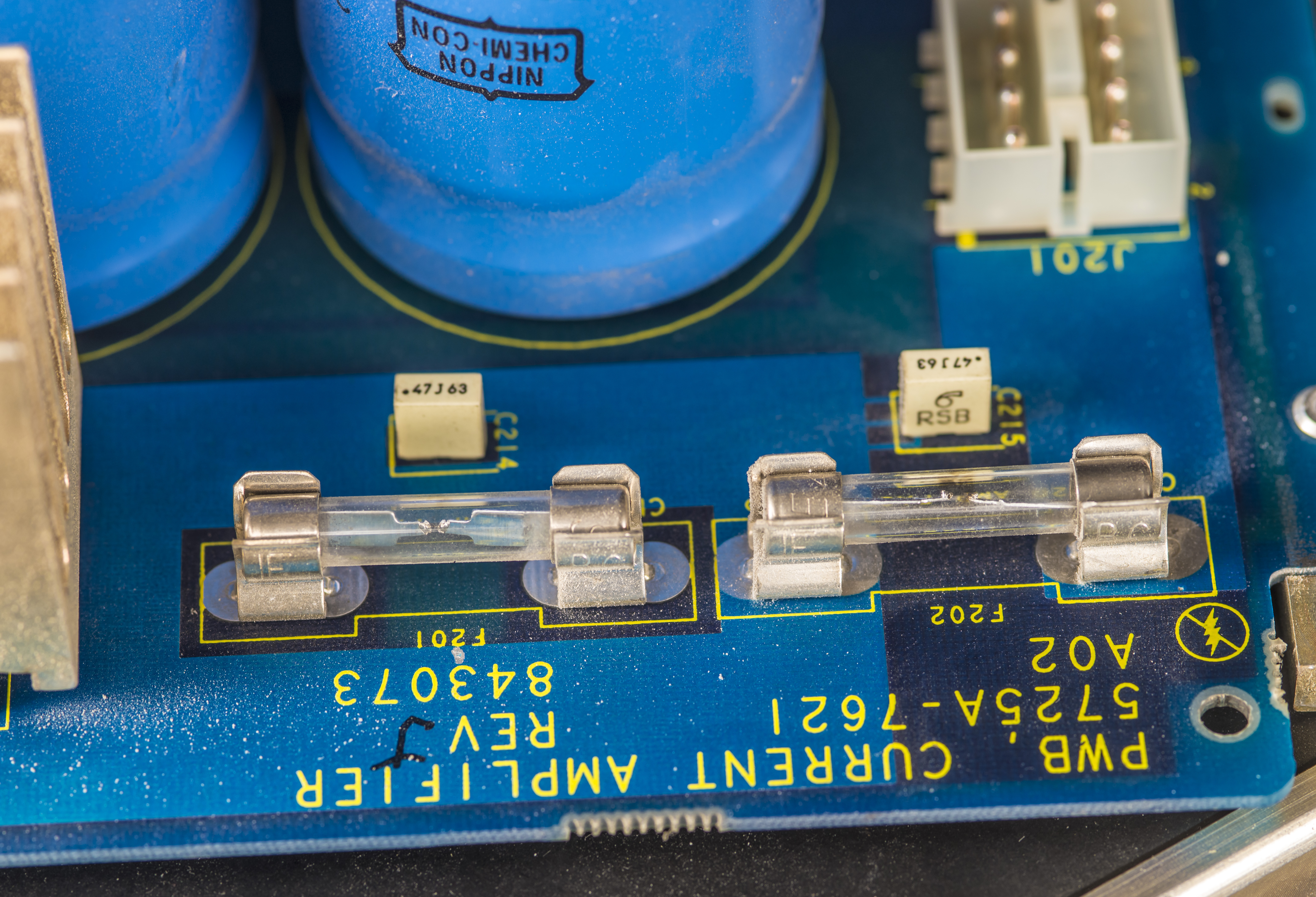
Both F201 and F202 fast-acting 20A fuses are very blown. These fuses are installed before high current CR206 diode bridge to protect power transformer. Massive 50000 µF capacitors are used to filter +12I and -12I rails levels. There is no voltage regulator used for these supplies since absolute voltage is not that important for current output stage.

Instrument also got pretty dusty since it was operated for number of years non-stop and to help with temperatures no filter was attached to large and fast 120mm x 38mm fan.
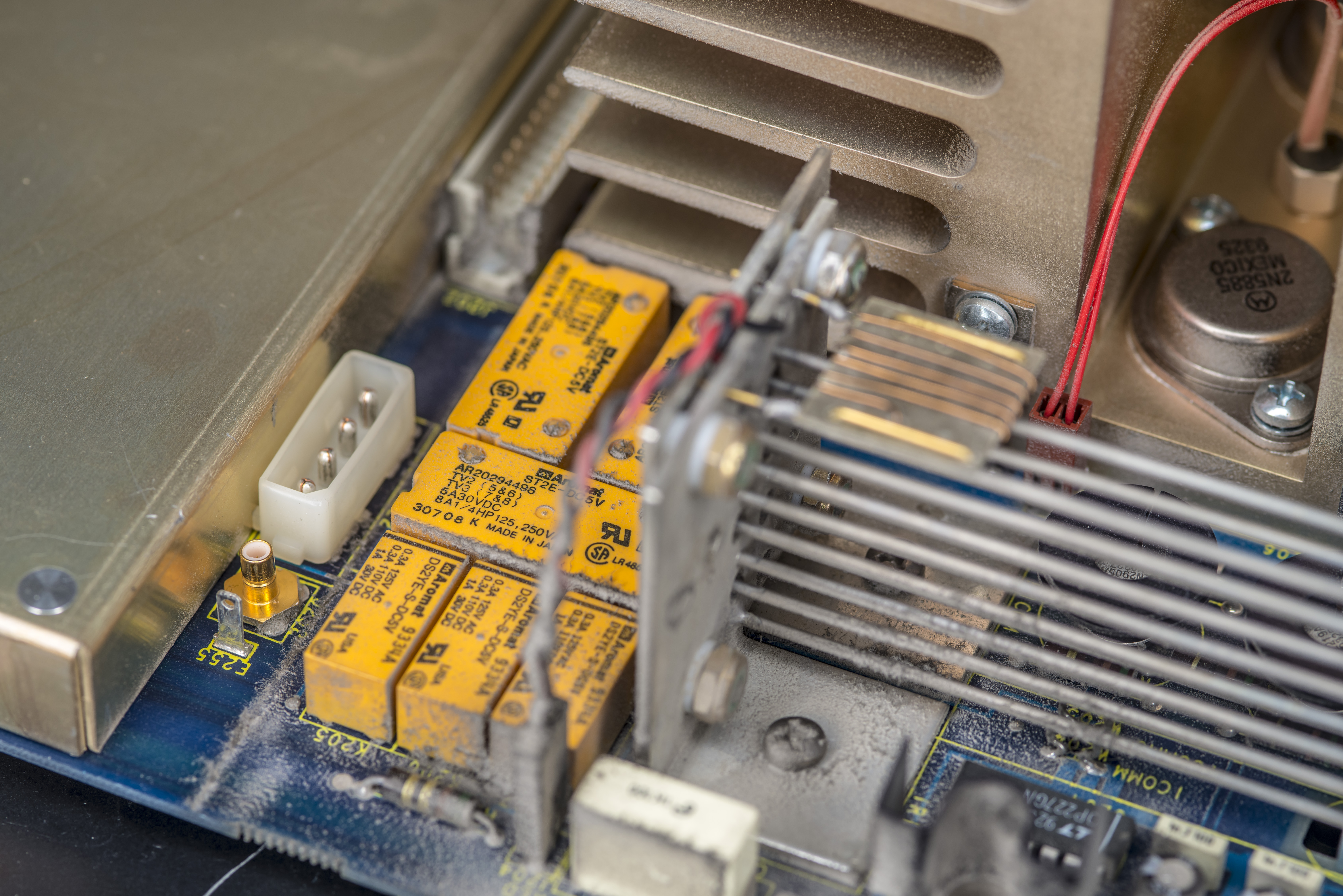
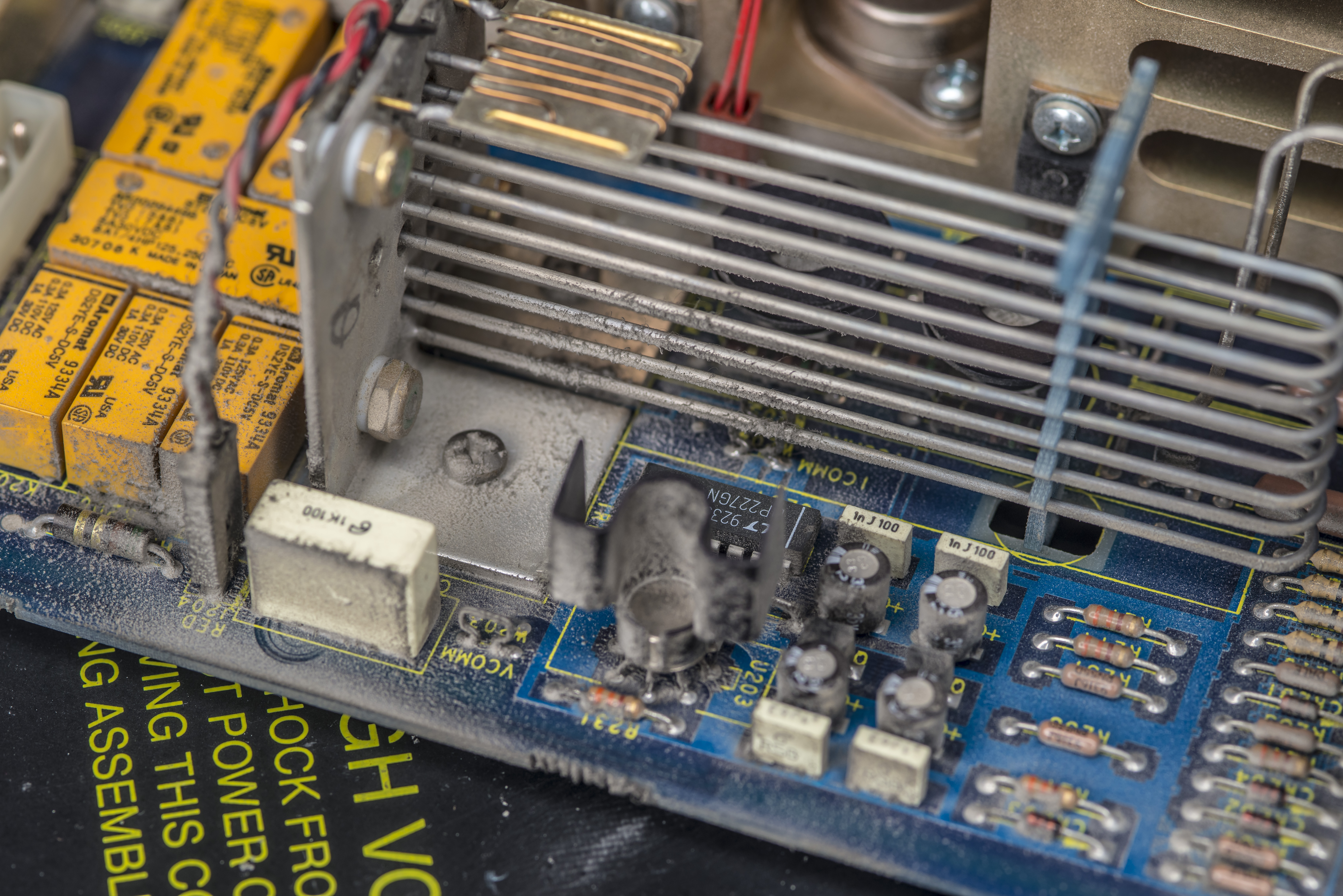
All this dust is cleaned up shortly after this photo was taken.
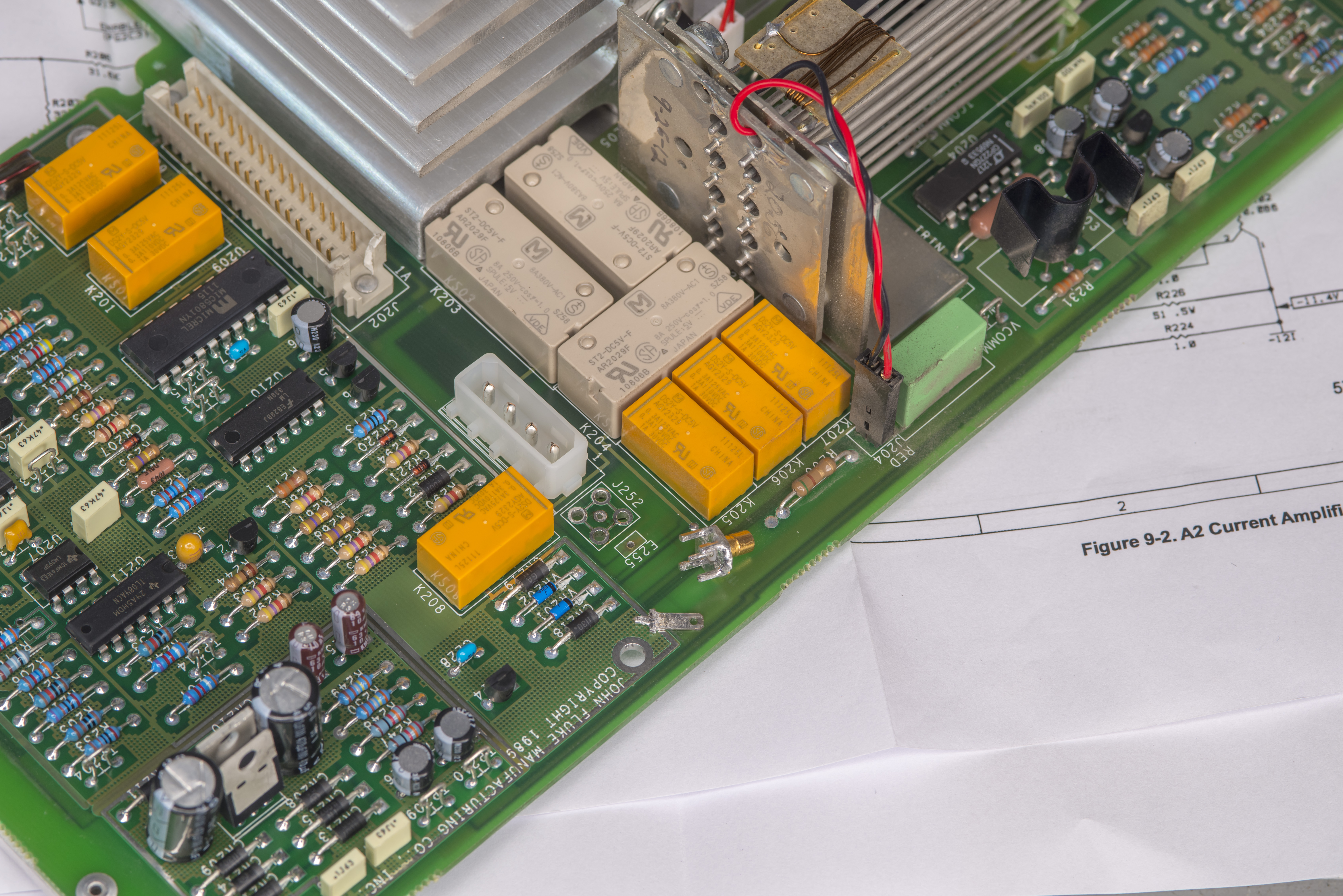
High current assembly is a linear transimpedance amplifier with stiff +/-12V rails and bunch of high power parts.
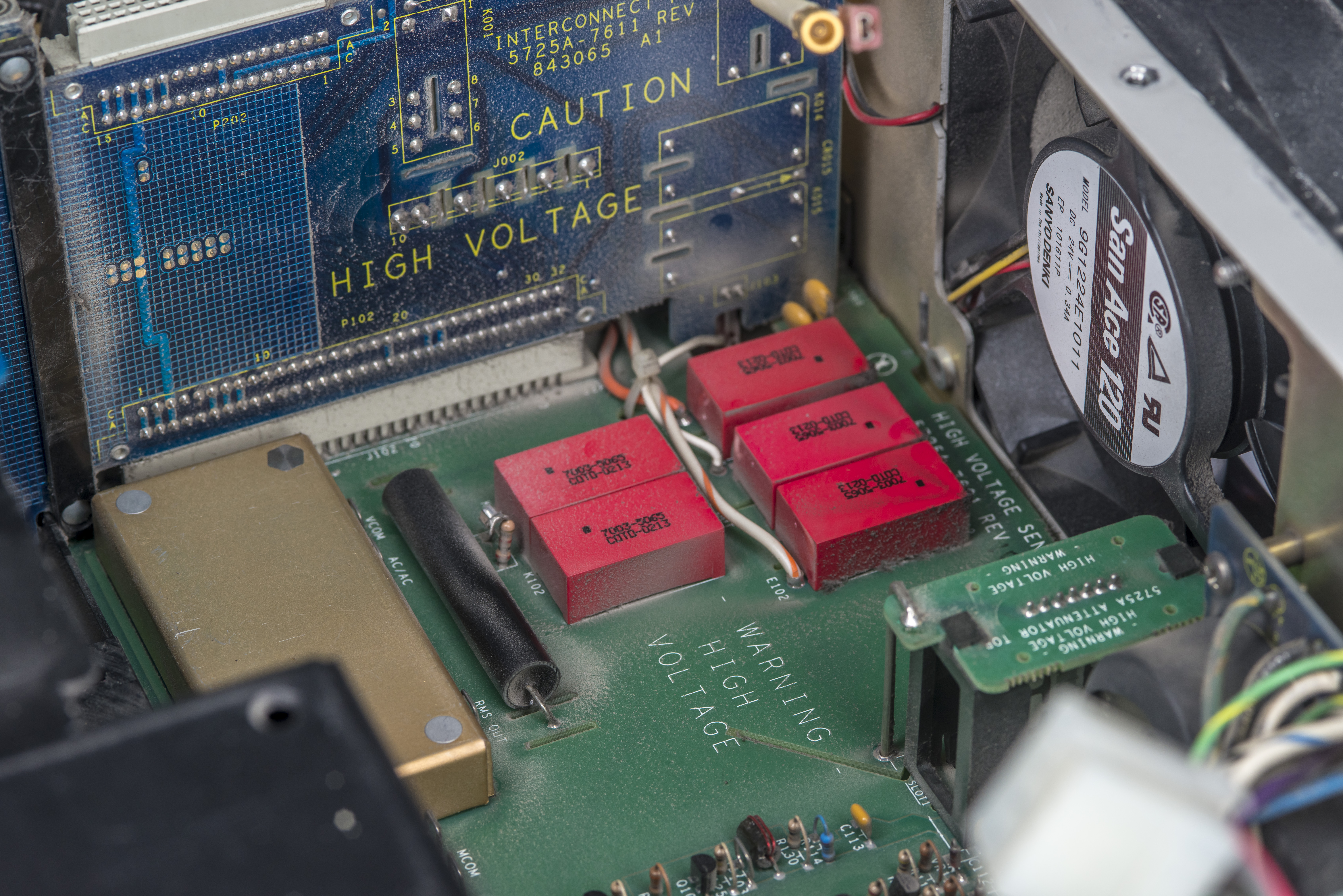
Green bottom on the board is separate section of the instrument, responsible for high-voltage 1100V ACV range.
Sadly after putting good fuses back into the instrument it still remained broken. Positive DC output on 11A current range started to work, but attempt to output any negative DC output voltage immediately tripped protection and shut off the output. So we have something really broken in the high-current output stage, perhaps pass transistors as they are first in line to get the damage?

Guess what, those suspect 2N5883 and 2N5885 transistors in TO-3 package are non-stocked anywhere and quite expensive at $44 and $68 USD. MJE15029 and MJE15028 are available though, little wins at least here.
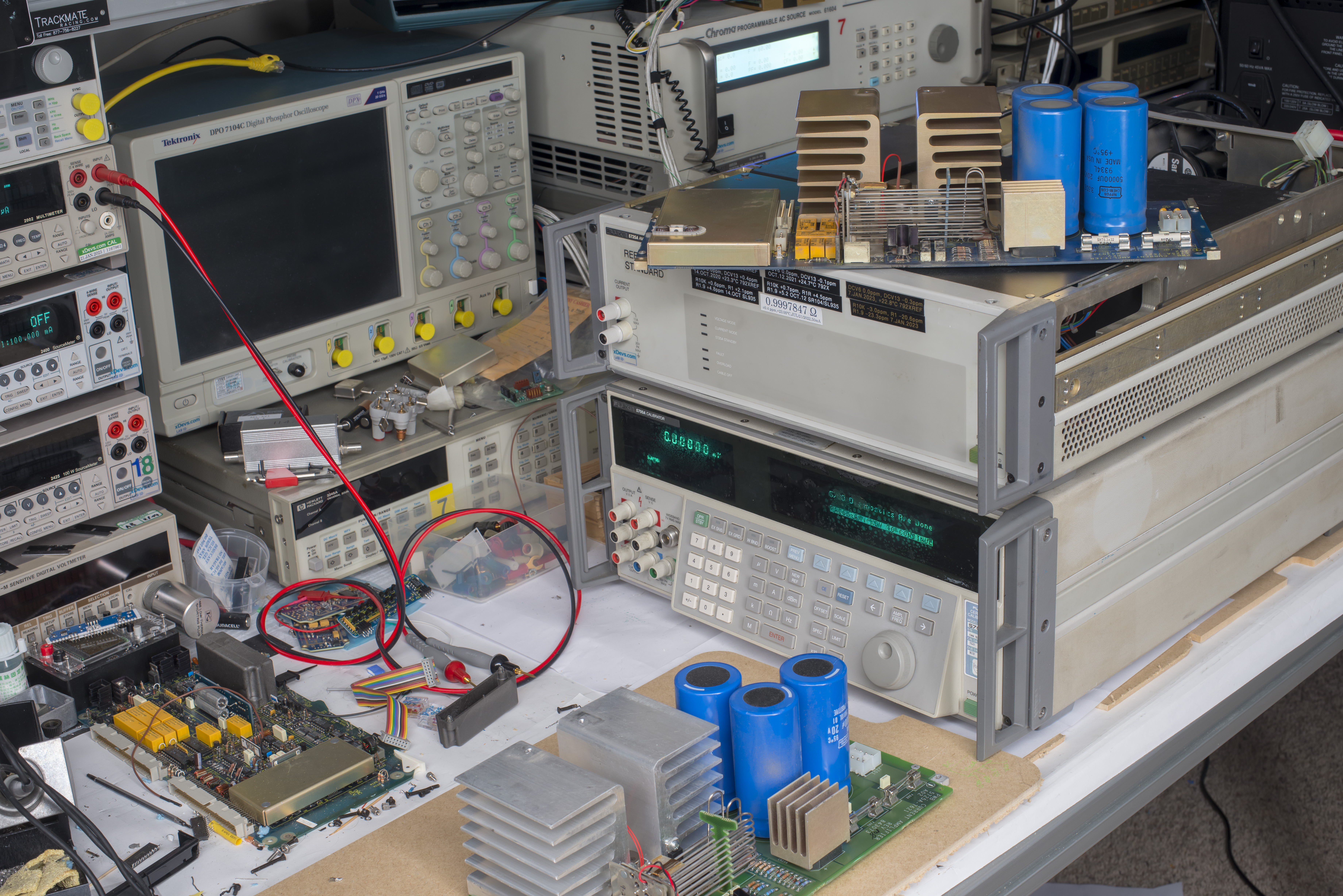
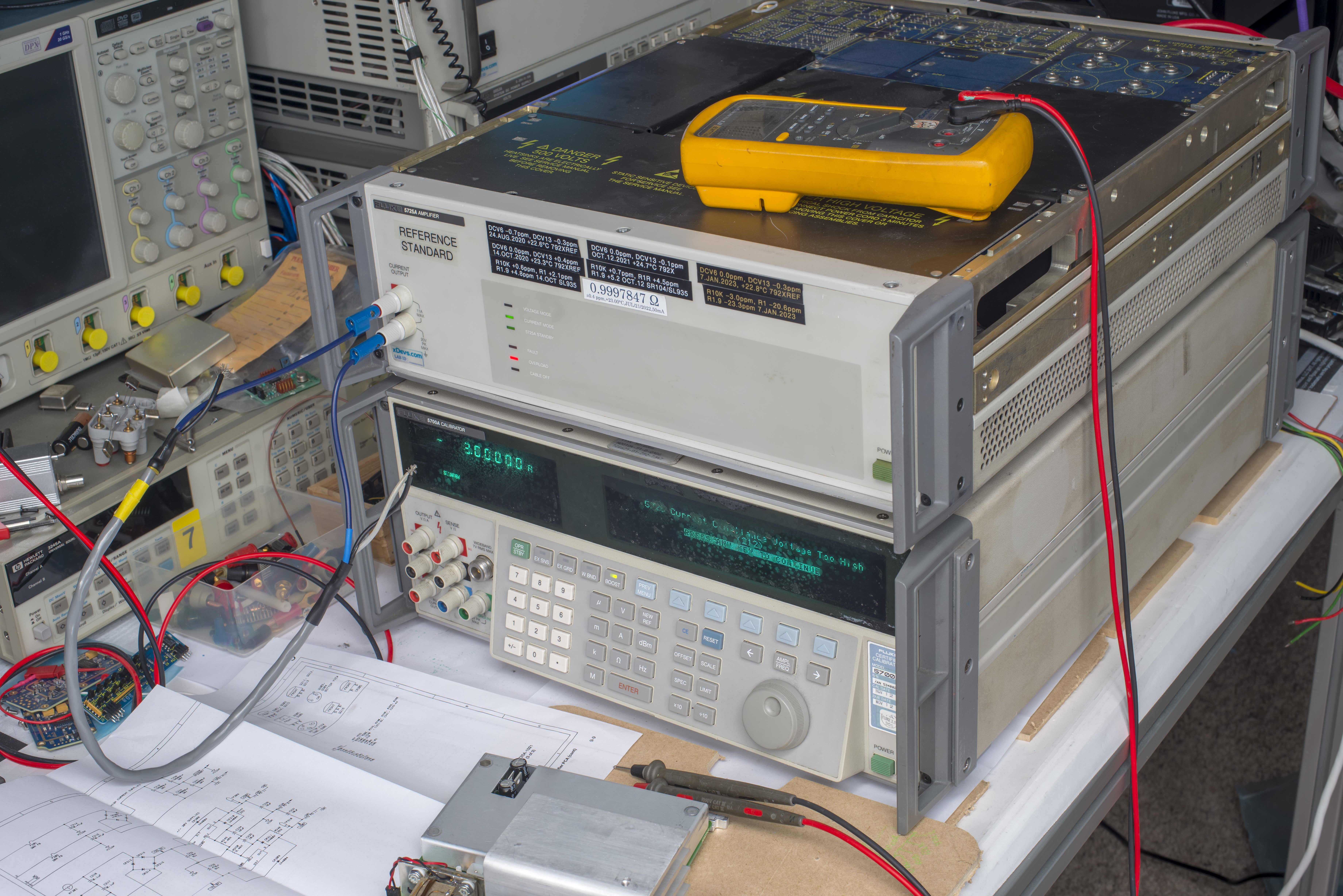
For now need to haul heavy 5725A onto the bench and have another 5700A available nearby to test the output stage next. 5725A can only be controlled by calibrator, there is no way to make it source currents on it’s own without the proper connection to calibrator, unlike more modern Fluke 52120A high-current amplifier.
Update from 13.NOV.2023
Thanks to friendly support I’ve got a separate test 5700A calibrator on a bench to troubleshoot sick 5725A amplifier. 5700A was verified to properly operate without amplifier to make sure there are no other problems that would prevent us good repairs and tests.
After connecting 5725A and operating with +3.0A DC test current it was confirmed working, just like with my primary 5720A. Negative or AC current of any value on 11A range would instantly trip the 5725A into protection mode with “5725 Current Compliance Voltage Too High, Error 212”.
At least we have now consistant behaviour with three different calibrators and two interconnect cables. I’ve measured bias voltages at the bases of output stage transistors and observed some disbalance in voltages. Base of Q205 was reading +11.2 V and base of Q206 was reading at -4.7 V. According to service manual bases should stay at same voltage around 9.9 V and -9.9 V. This is linear amplifier stage so it should be balanced pretty well around zero with output current near zero volts.
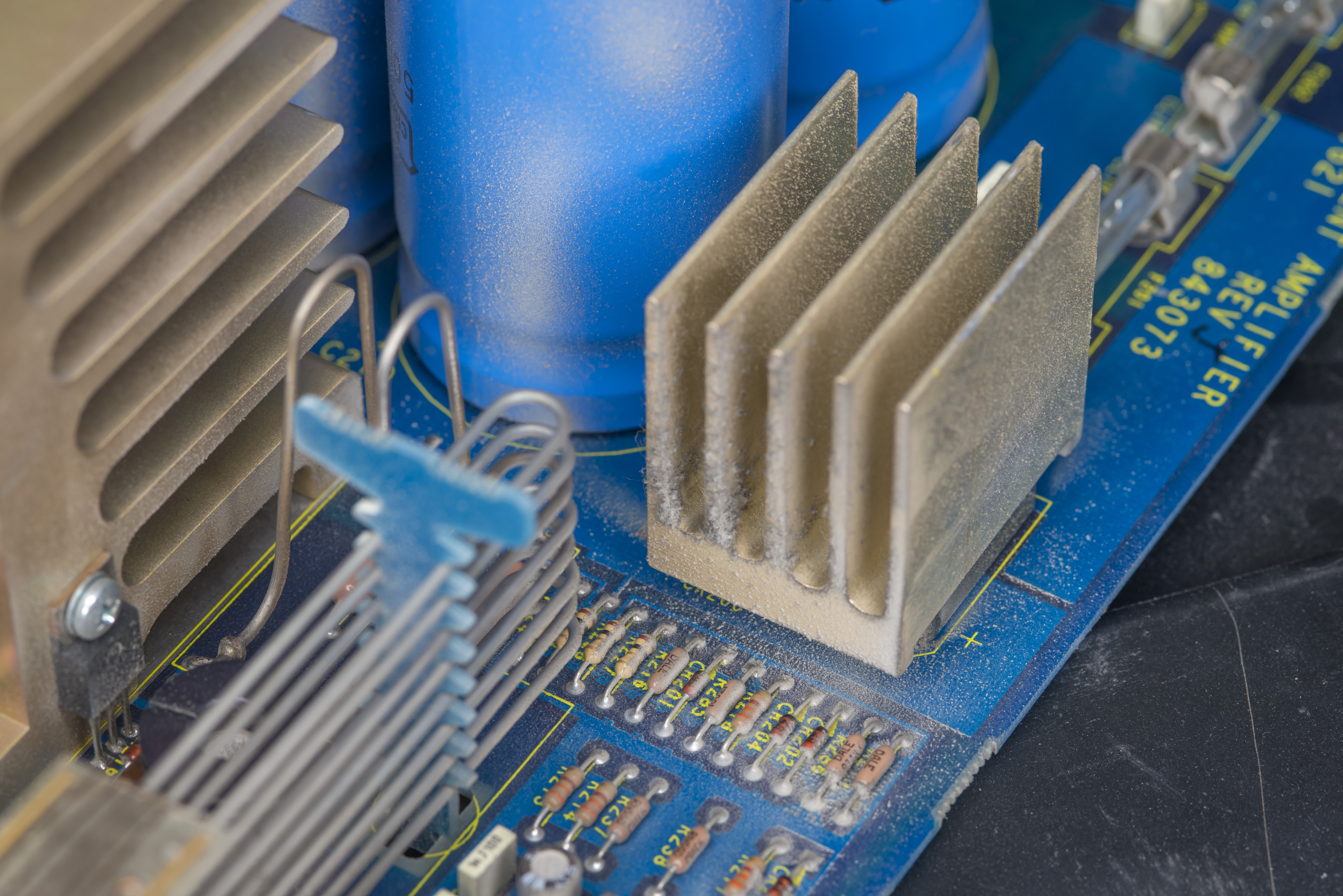
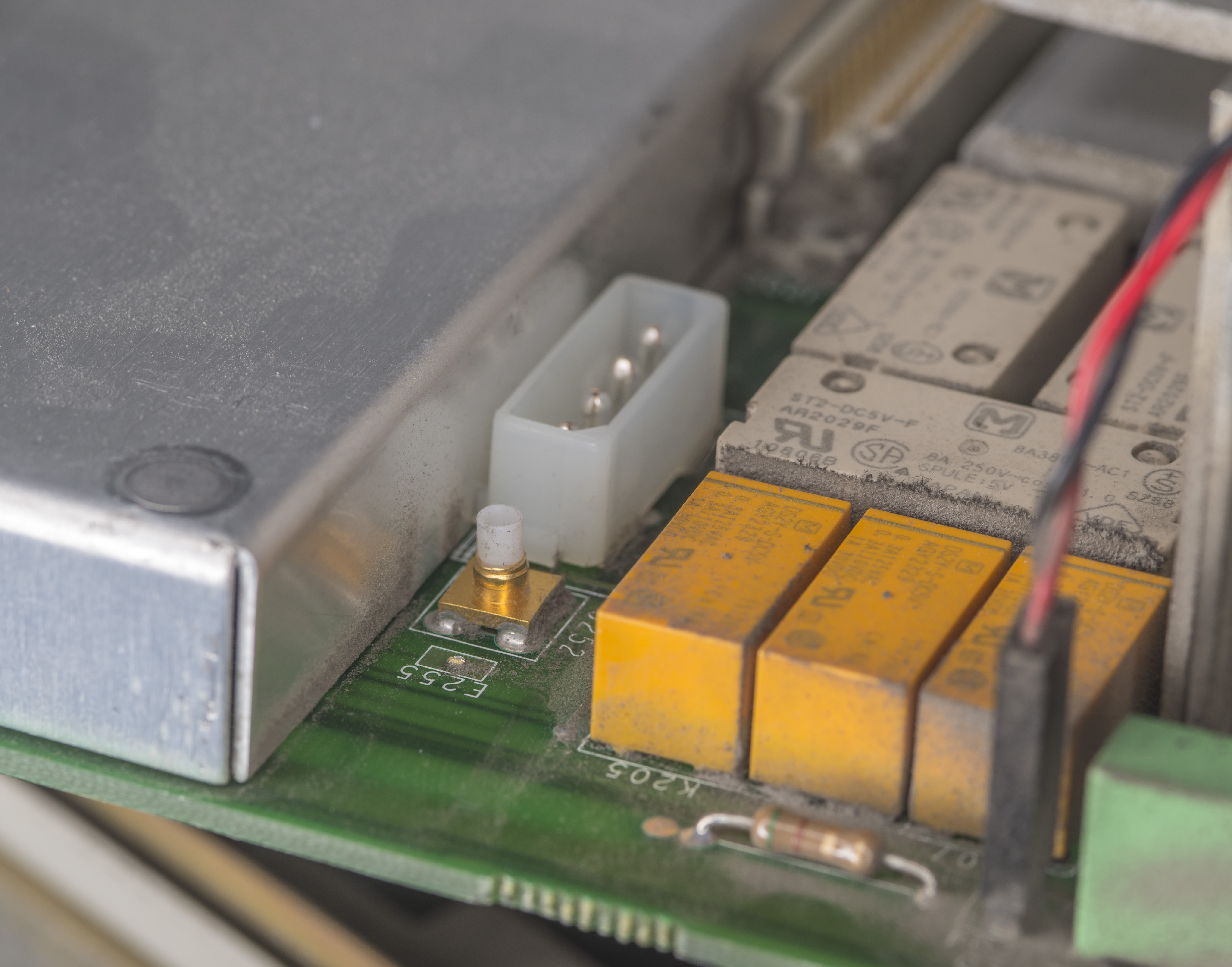
To aid with the troubleshooting I’ve also got another newer 5725A A2 Current assembly module. This green colored PCBA has label 5725A-7621 P/N 843073 and BOM revision 108 with PCB layout revision P. According to datecodes on chips this module was manufactured around week 17 in 2012. It is also came from broken and untested 5725A so we could at least test some parts from it and compare if needed. Interestingly second A2 amplifier also have damaged fuse, however it is not open (yet):
Another damage detected on this newer PCBA – busted up SMB connector and 3mm wide tab point for the cable from high voltage/thermal RMS board. And this green PCB also missing one of those huge 50000 µF 20V capacitors. Ofcourse these Chemi-Con 36DE503H020EL2A capacitors are now obsolete and unobtainable. Most of modern capacitors of similar specs and capacitance are larger in diameter and have different mount screw pin pitch. Original capacitors are U3L size which specify 44.5 mm diameter , 92.0 mm length and 19mm screw terminal tabs pitch. CGS series capacitor part-number with these parameters would be CGS503U020U3L3PL which would be a special custom order.
Possible replacement capacitor models from Cornell Dubilier would be something from series 101C, DCMC or CGS series such as 101C503U020EH2B, DCMC603U025EB2B, DCMC543U035EJ2B but none of them are available without MOQ of 50pcs and lengthy leadtimes. Usually this is fine for development of the product, but not for one-off repair like outlined in this article.
To mitigate broken connectors I’ve took them from my older PCB. Also I borrow capacitor as well to see if green board have issues or actually can work. I love how 5725A is designed with easy access to most of the test points and modules without need of any advanced disassembly. This is one of the differences between bad system design and good products.
Even chassis has little CNC-ed pockets in the side frame to fix heavy PCBA in a service position for connecting all cables and making sure nothing interferes in the assembly process later on. After powering both 5700A and 5725A with patched up green A2 PCBA system passed self-test and was able to output correct high currents in both positive and negative polarity. AC current was also checked and confirmed working.
Now that I got working module, I could remeasure same points at Q205 and Q206 for the good reference readings. Voltages were reading +10.5 V and -10.5 V according to my calibrated Keithley 2002 DMM. As expected output stage operated pretty well balanced.
Now time to get back to broken original blue board. Back in 2018 when I acquired 5725A I’ve replaced all capacitors and carbon composition resistors on high voltage PCBAs. But few of carbon composite resistors on current PCBA were left as original. These type of resistors are known to drift a lot (more than 20% in many cases) over the years and are common failure in older test equipment. Fluke replaced all carbon composition resistors in 5700/5720/5730/5725 BOMs starting from late 2000s years.
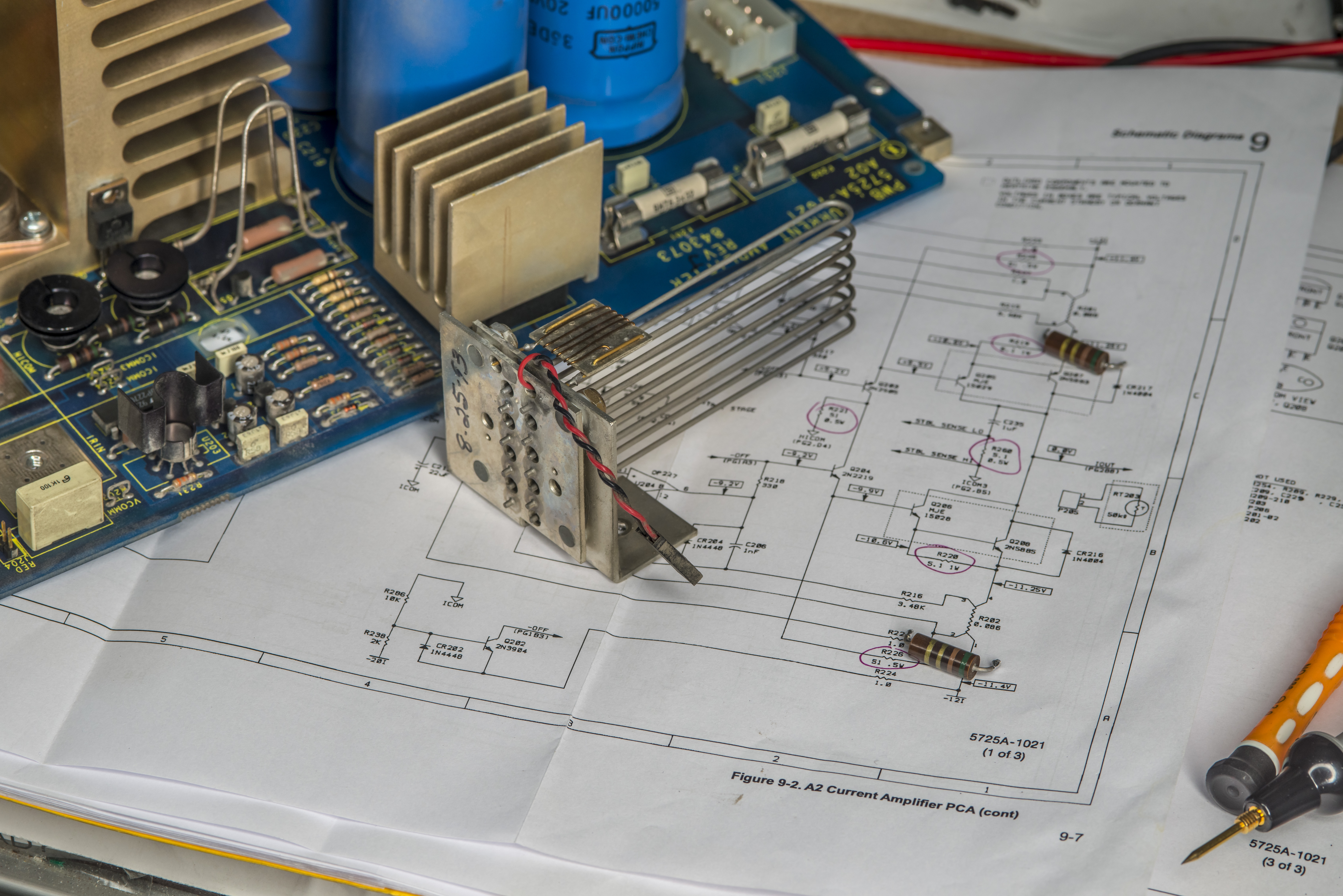
My old A2 PCBA from 5725A use three kinds of carbon composite resistors :
- 5.1 Ω 5% 1W for output power stage emitters
- 51 Ω 5% for bias current on transistors
- 5.1 Ω 5% 0.5W for sense feedback between output and ICOM3 return path
I’ve desoldered R219 and R220 and first measurements with K2002 revealed obvious problem:
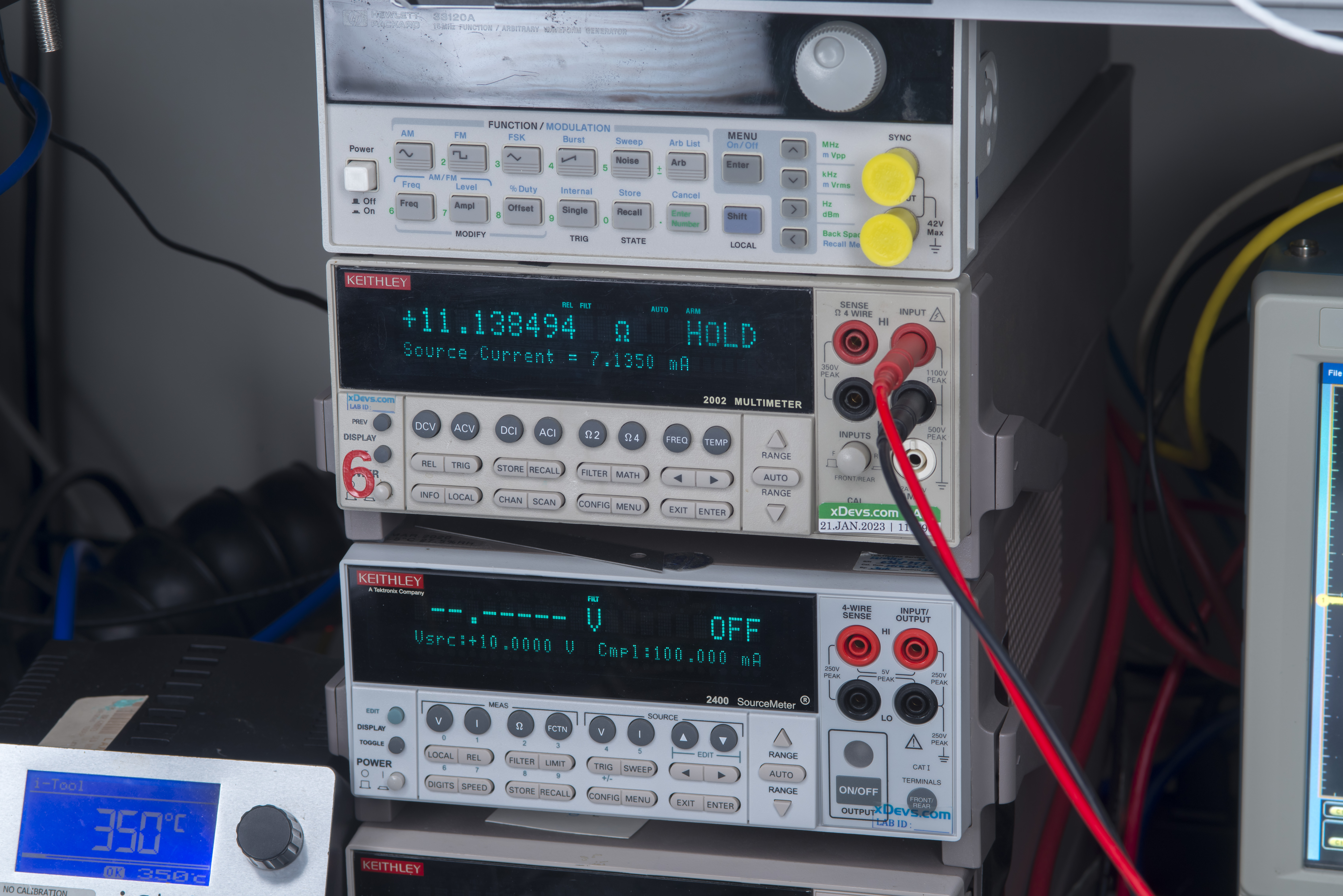
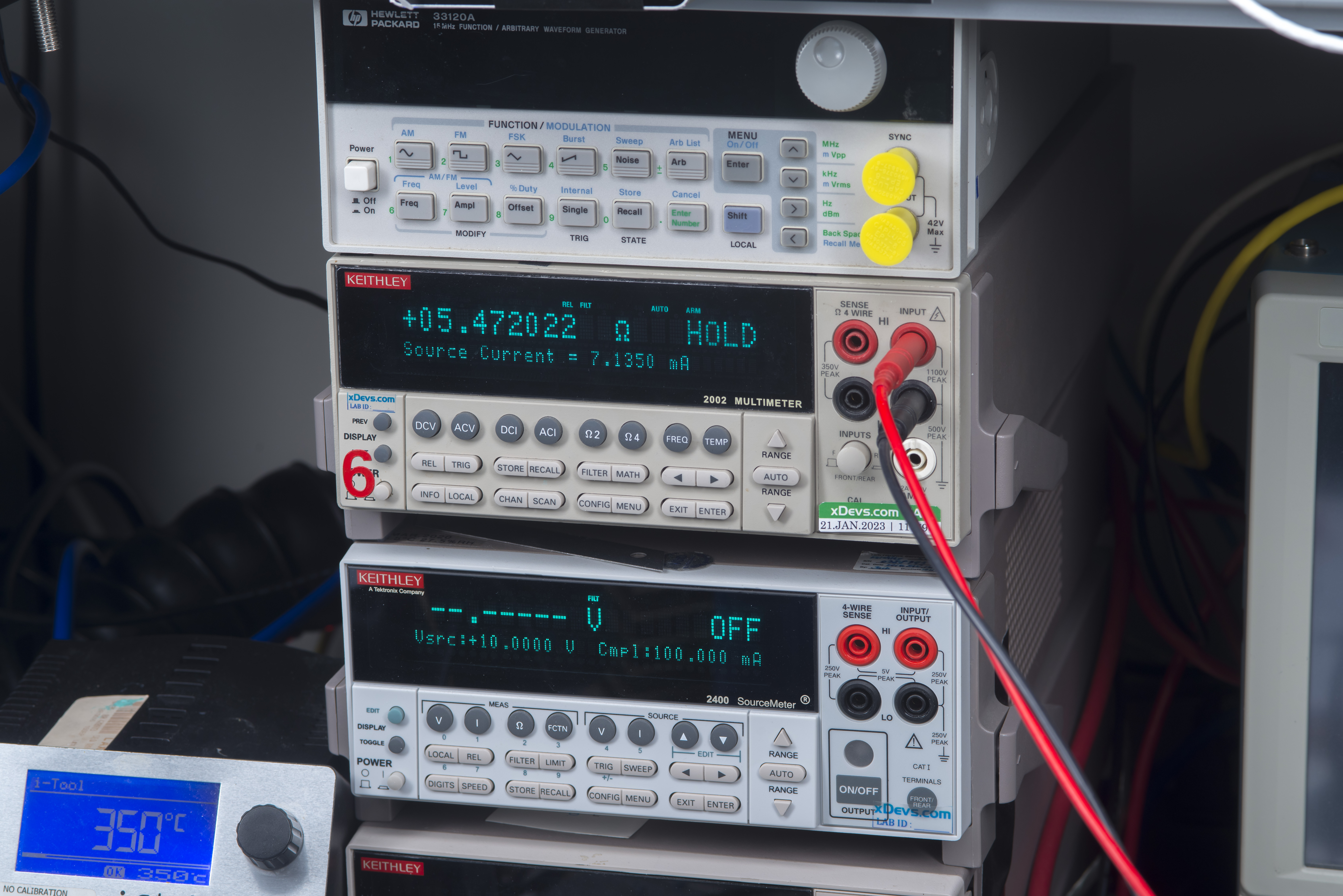
What supposed to be R220 5.1 Ω resistor is now 11.14 Ω one, which is off by huge 118%. Second R219 resistor measured at 5.47 Ω which is “only” 7.3% off the nominal 5.1 Ω. Not that it will save it anyway, all carbon composition type resistors will be gone next week before I continue testing, to see if any other parts are blown.
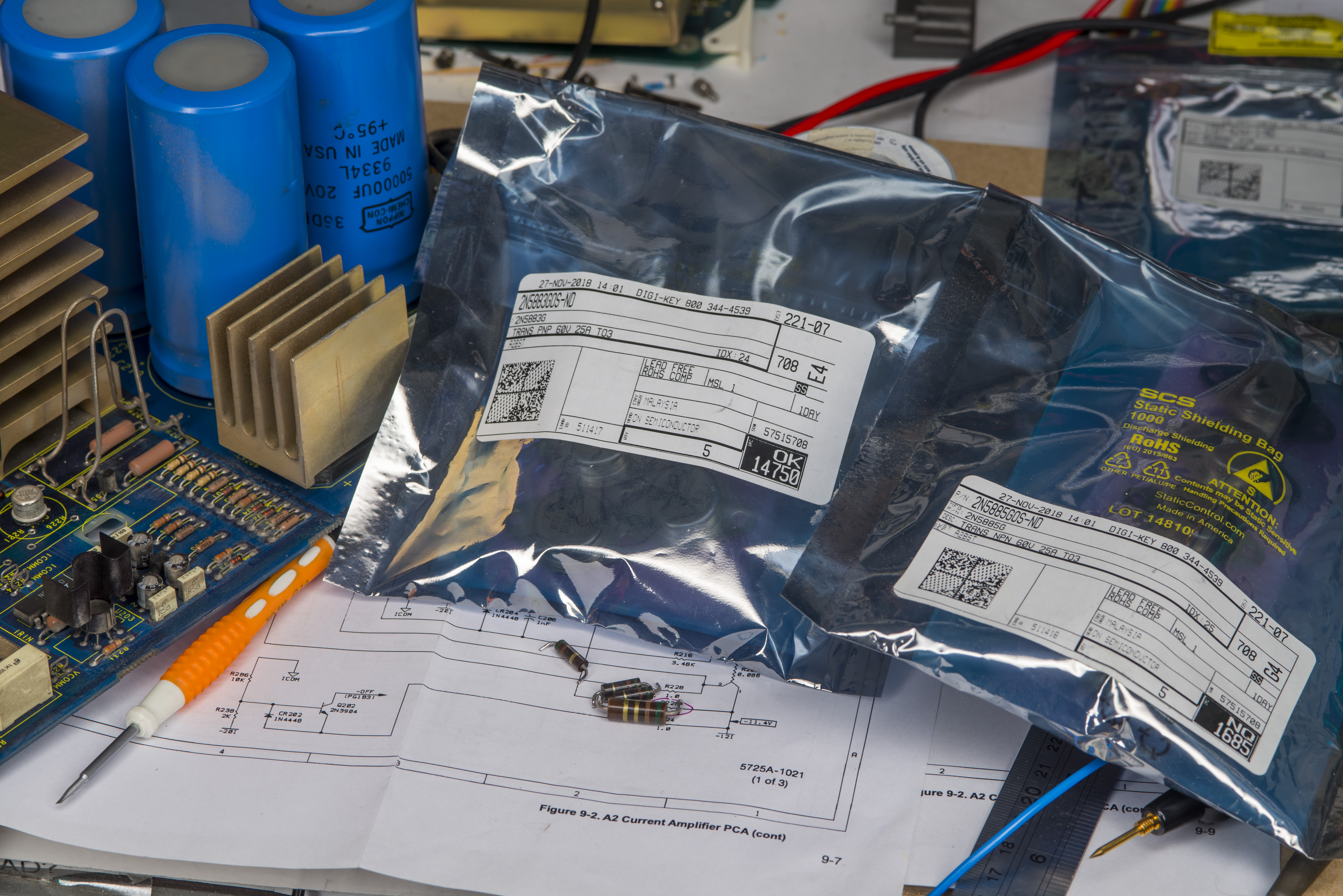
After checking my stockpiles I actually discovered my preparations for 5725A repairs from year 2018, which included hard to find TO-3 power transistors 2N5883 and 2N5885. Never underestimate power of hoarding electronic components, even when you don’t need them right now. With modern world progressing towards digital and commodified electronics finding old components in TO, DIP or even SOIC packages becoming harder and harder.
Now off to Digikey to order some replacement resistors and parts to continue with next step in repairs.
| Digikey P/N | Component | Qty | Cost (13.NOV.2023) |
|---|---|---|---|
| WM5528-ND | Molex, CONN SMB RCPT STR 50 OHM PCB | 1 | $3.18 |
| 36-1250-ND | Keystone Electronics, PC TEST POINT LOOP | 1 | $0.203 |
| PPC5.1W-2CT-ND | RES 5.1 OHM 2W 5% AXIAL | 3 | $0.801 |
| A129360-ND | RES 51 OHM 1% 1W AXIAL | 3 | $2.217 |
| 507-1622-ND | FUSE CERAMIC 20A 250VAC 3AB 3AG Fast Blow | 2 | $2.758 |
| 338-2090-ND | CAP ALUM 68000UF 20% 25V SNAP as bodged alternative | 1 | $14.63 |
| Total with shipping | $36 USD | ||
Modified: Nov. 13, 2023, 10:44 p.m.