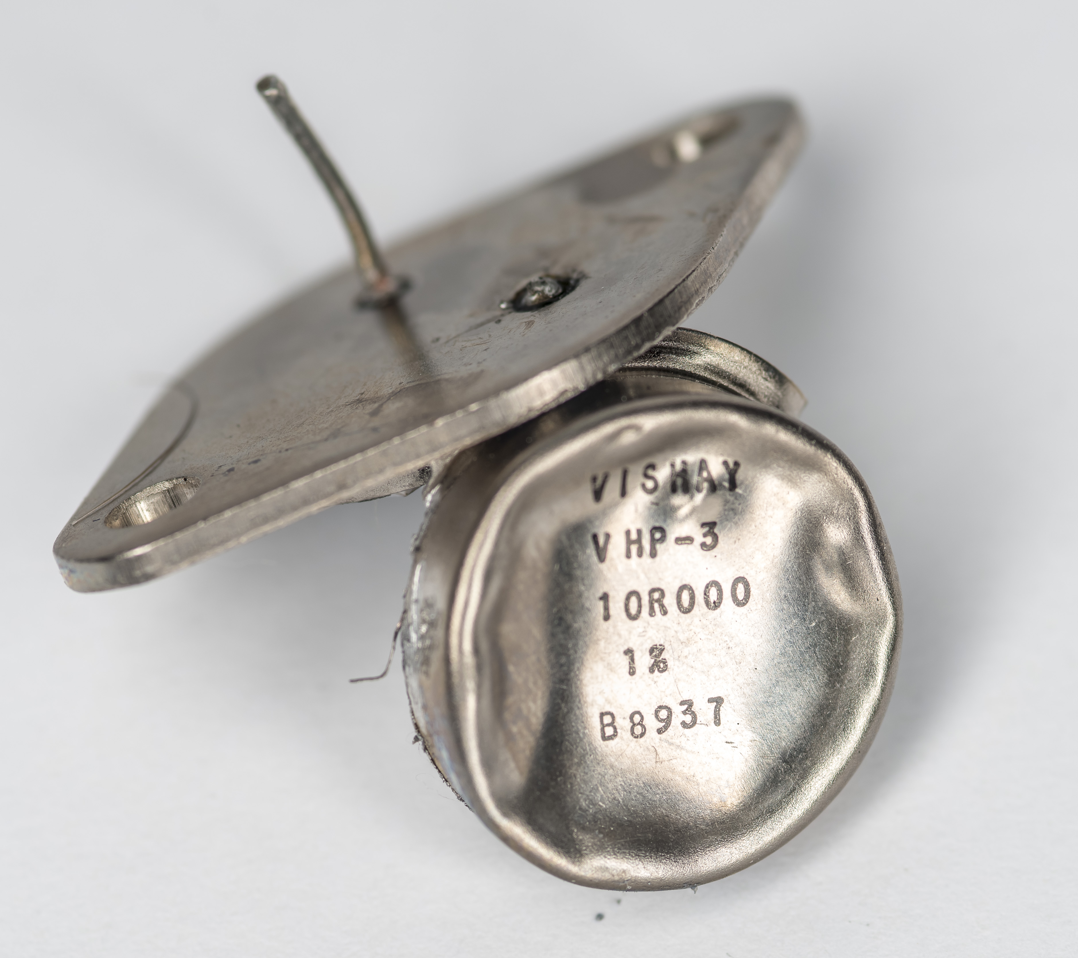
Returning back to resistance topic, this time Igor donated a damaged Vishay Precision Group VHP-3 10 Ω resistor for tear-down.
VHP-3, VHP-4 and VPR247 datasheet
It was crushed from the top and had one of the copper terminals broken off, so it’s time to cut it open and take a look inside. These resistors are also hermetically sealed with nitrogen fill for the protection against environmental stresses, thereby ensuring long term stability.
VHP-3 and VHP-4 are also using set of BMF elements but with main focus on low resistance and higher power rating, compared to more popular VHP100/200 series SKUs.
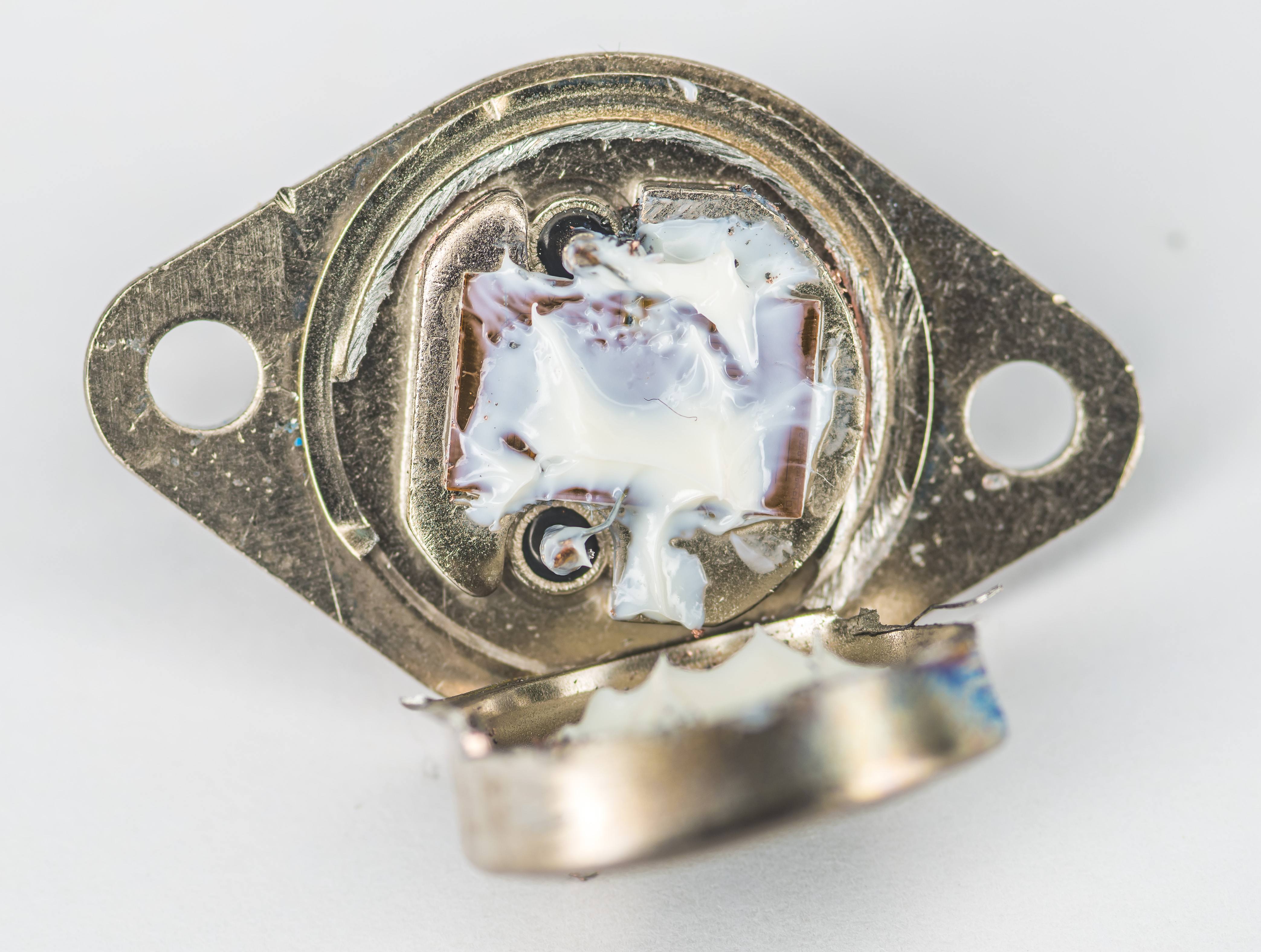
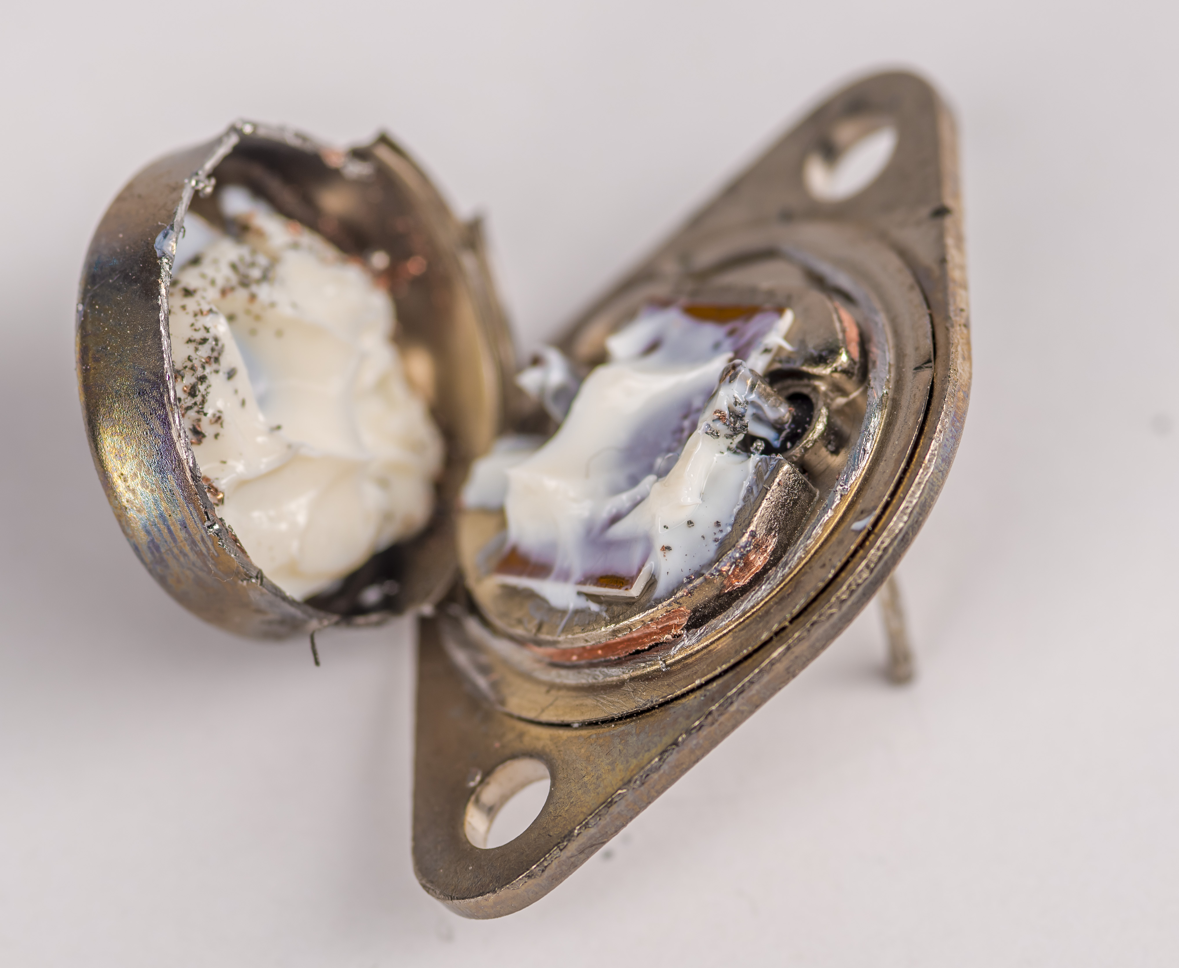
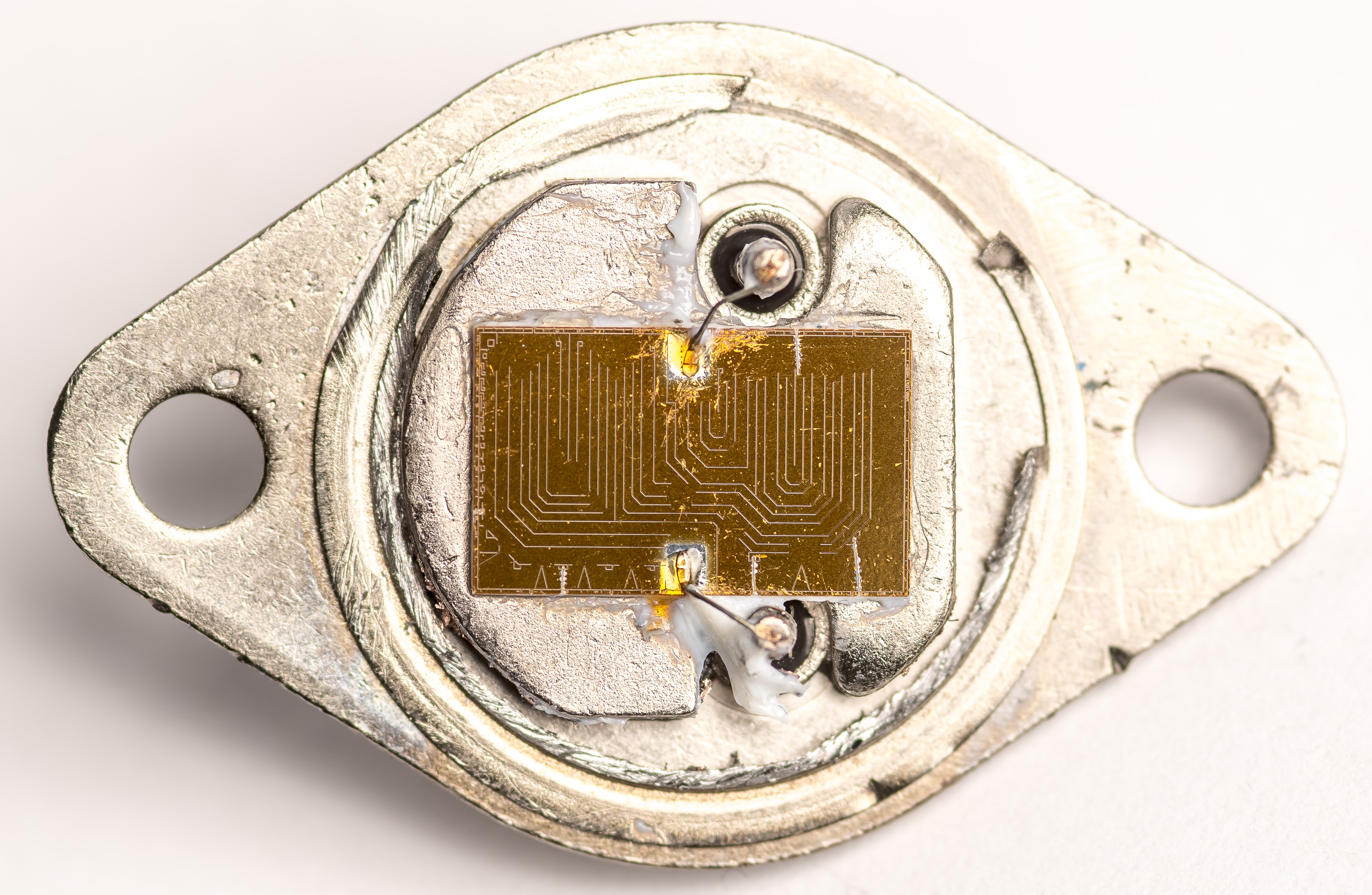
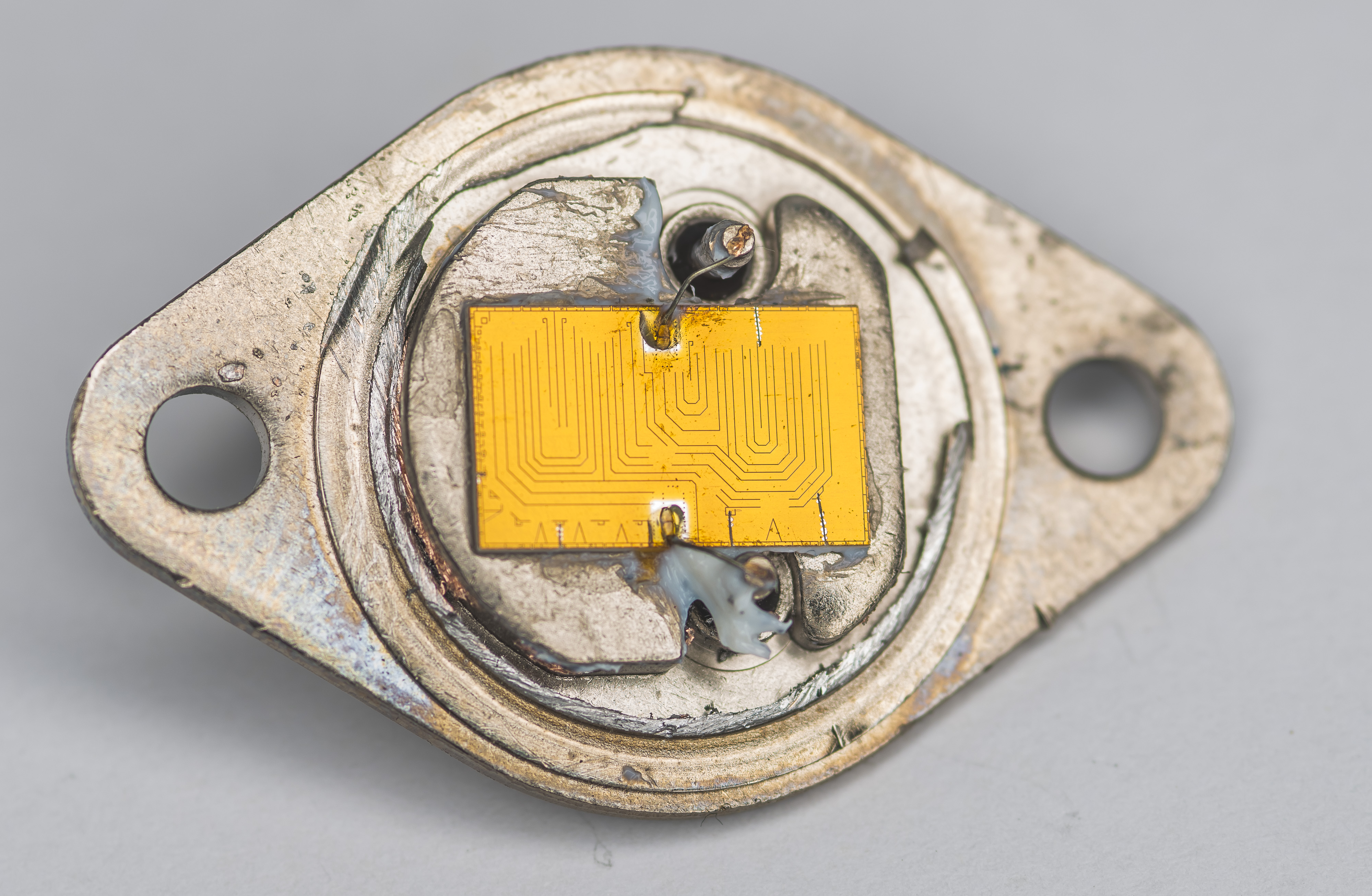
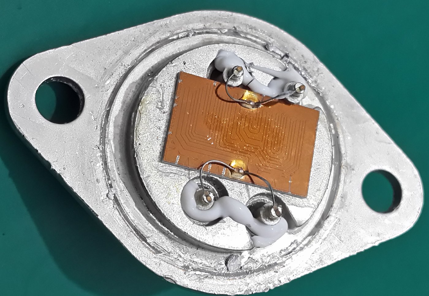
Rather large resistor element is mounted on thick copper nickel-plated heat spreader plate welded to the TO-3 case. On top we can see white thermal compound spread around. Much more of it remained in the cap lid as well.
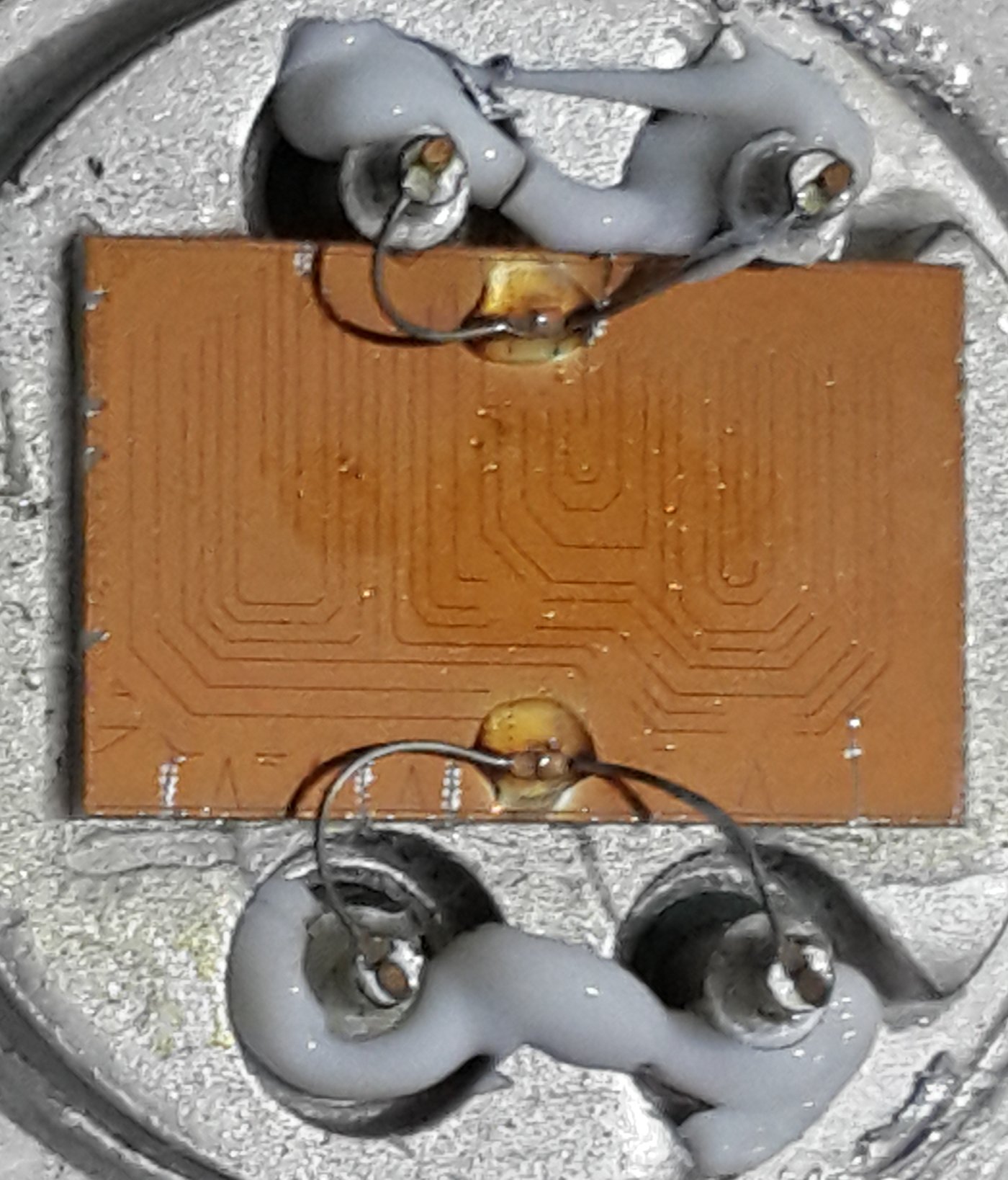
After cleaning the grease off we can see thick metal foil resistive element with some cut patterns. Thick wirebonds connect middle point of BMF element to the vertical copper terminal from TO-3 case.
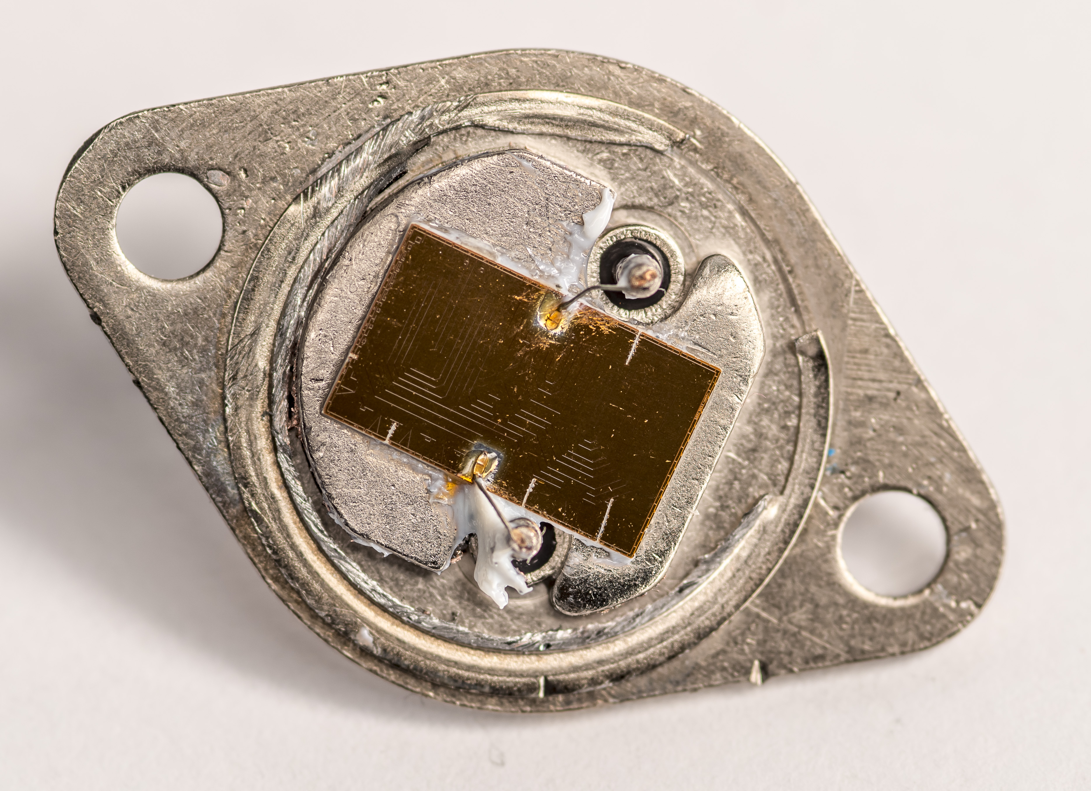
With light positioned on proper angle the element lithography pattern becomes very clearly visible, with some adjustment trims on the sides as well.
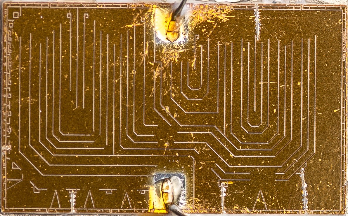
Pattern has features to laser cut and isolate various size segments to increase resistance of the element for fine-tuning final resistance.
VHP-3 and VHP-4 are available for nominal power around 10 W with heatsink or 3 A and can have much lower resistances, down to 0.05 Ω or even less for special order. Without heatsink these resistors capable to run with loading up to 3 W.
VHP-3 have best TCR ±5 µΩ/Ω and worst at ±50 µΩ/Ω depending on resistance value. I’ve summarized the specifications in a table below.
| Resistance | Best tolerance | Maximum TCR VHP-3 | Maximum TCR VHP-4 and VPR247 |
|---|---|---|---|
| 50 Ω – 80000 Ω VHP-3 only | ±0.01 % | ± 5 µΩ/Ω | |
| 25 Ω – 50 Ω | ±0.02 % | ± 7 µΩ/Ω | |
| 10 Ω – 25 Ω | ±0.05 % | ± 10 µΩ/Ω | |
| 10 Ω – 500 Ω | ±0.01 % VHP-4 | ± 5 µΩ/Ω | |
| 5 Ω – 10 Ω | ±0.1 % VHP-3, ±0.01 % VHP-4 | ± 13 µΩ/Ω | ± 6 µΩ/Ω |
| 2 Ω – 5 Ω | ±0.25 % VHP-3, ±0.05 % VHP-4 | ± 20 µΩ/Ω | ± 8 µΩ/Ω |
| 1 Ω – 2 Ω | ±0.5 % VHP-3, ±0.1 % VHP-4 | ± 25 µΩ/Ω | ± 10 µΩ/Ω |
| 0.5 Ω – 1 Ω | ±1 % VHP-3, ±0.25 % VHP-4 | ± 50 µΩ/Ω | ± 15 µΩ/Ω |
| 0.25 Ω – 0.5 Ω | ±2 % VHP-3, ±0.5 % VHP-4 | ± 50 µΩ/Ω | ± 20 µΩ/Ω |
| 0.1 Ω – 0.25 Ω | ±5 % VHP-3, ±1 % VHP-4 | ± 50 µΩ/Ω | ± 25 µΩ/Ω |
| 0.05 Ω – 0.1 Ω VHP-4 only | ±2 % VHP-4 | ± 30 µΩ/Ω |
Here are also few photos we got years back for 4-wire 0.1 Ω VHP-4 resistor. Interesting to note much different thickness of the foil bondwires used for current pins and sense pins.
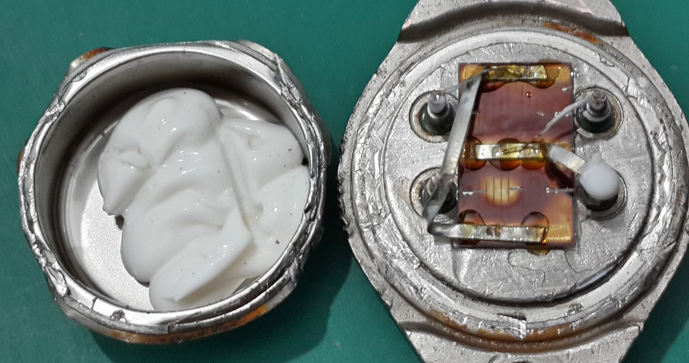
And photo of 10 Ω VHP-4 4-wire resistor. It use exactly the same chip element pattern as VHP-3 from today, but use four bondwires to provide kelvin connection to the element.
Unlike low 0.1 Ω type here each of the bondwires are same size.
Discussion is very welcome thru comment section or at our own IRC chat server: xdevs.com (port 6010, channel: #xDevs.com).
Modified: April 16, 2024, 3:29 a.m.