Contents
- Intro
- Exterior
- Interior
- Service
- Test software for scanner
- Some benchmarks of DataProof scanners
- Conclusion
Introduction
In this article metrology-grade multichannel scanner from Data Proof will be reviewed and serviced. Model evaluated is Data Proof 160, which feature 16 channels with direct cable input. The Data Proof low thermal scanner was designed to perform series opposition measurements of standard cells. The design is based on the recommendation from NBS (now NIST) published in the NBS Technical Note 430. The document was published in 1967 for use with standard cells, but it became the accepted method of measuring zener based references like the Fluke 732A or 732B.
The standard cells were sensitive to loads placed on them from lower impedance meters and accidental shorts. This could result in shifts in output voltages that could last weeks. The scanner has the ability to detect a relay is closed and will not allow another relay on the same side (A or B) to close. The signals come out to the rear of the scanner and can be connected to multiple scanners that are daisy chained to the system.
Specifications brief:
- Thermals typically less than ±20 or ±15 nanovolts, depending on option.
- Front Panel or GPIB remote operation
- Dual output configuration
- 16 inputs (32 for model 320)
- Four terminal measurements
- Standard cell protection
- Simple operation
Data Proof 160B/320B datasheet
Exterior
I’ve got two 16-channel units with two different input connection options. A couple of options were available with the scanner. Option 1 included pre-attached four conductor cables. These are basic telephone cables without shielding using a solid bare copper conductor. The cable listed in the parts list is a Belden 9794. They continue to use this cable with the B version.
Option 2 had 16 pairs of low thermal binding posts made by Pomona. These are the model 3770.
I have two option 1 and one option 2 scanners. The option 1 are more convenient as no additional cables are needed to connect voltage references. The wires, on one of the scanners, have insulation that has deteriorated. The plastic is cracking in multiple locations. The other scanner appears fine but it will be a matter of time before it suffers the same fate.
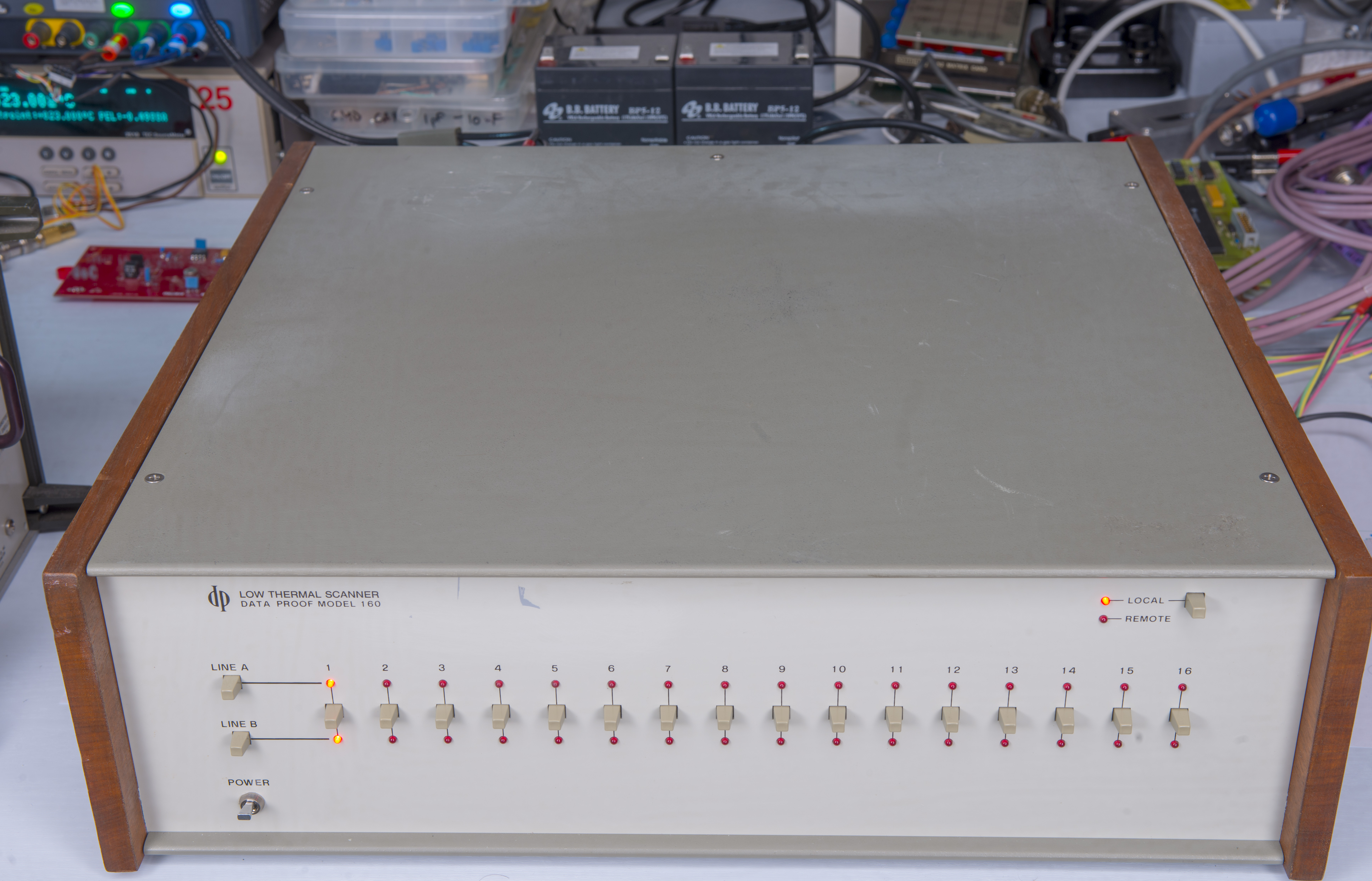
Front face look exactly same:

Image 1: Data Proof 160A
Rear panel is different:
Low thermal tellurium copper binding posts for Option 2 with gold flash.

Image 2: Data Proof 160A, Option 2 rear view
Cable version for Options 1, 3 and 4
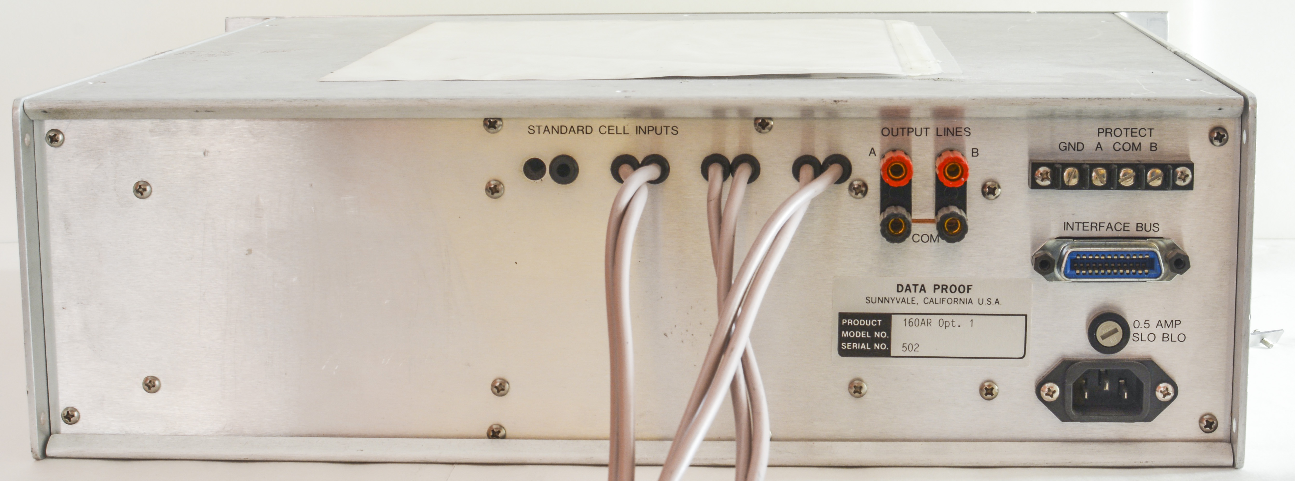
Image 3: Data Proof 160A, Option 1 rear view
Cable end is just unterminated bare copper wire available to connection with DUT.

Image 4: Data Proof 160A, Option 1 with cables
That’s it for appearance, operation is very simple with switch for each channel, and only rear connections available are power, output binding posts, protection terminal block and interface connector.
A 120ft quantity of Belden cable was purchased and the cables on both scanners will be replaced. One set of cables was removed and used to measure the length and location of the stripped ends. There is no mention in the manual of any special solder that was used. A new soldering iron tip and SN96/4 solder will be used to connect the new wires to minimize added thermal EMFs.
Interior
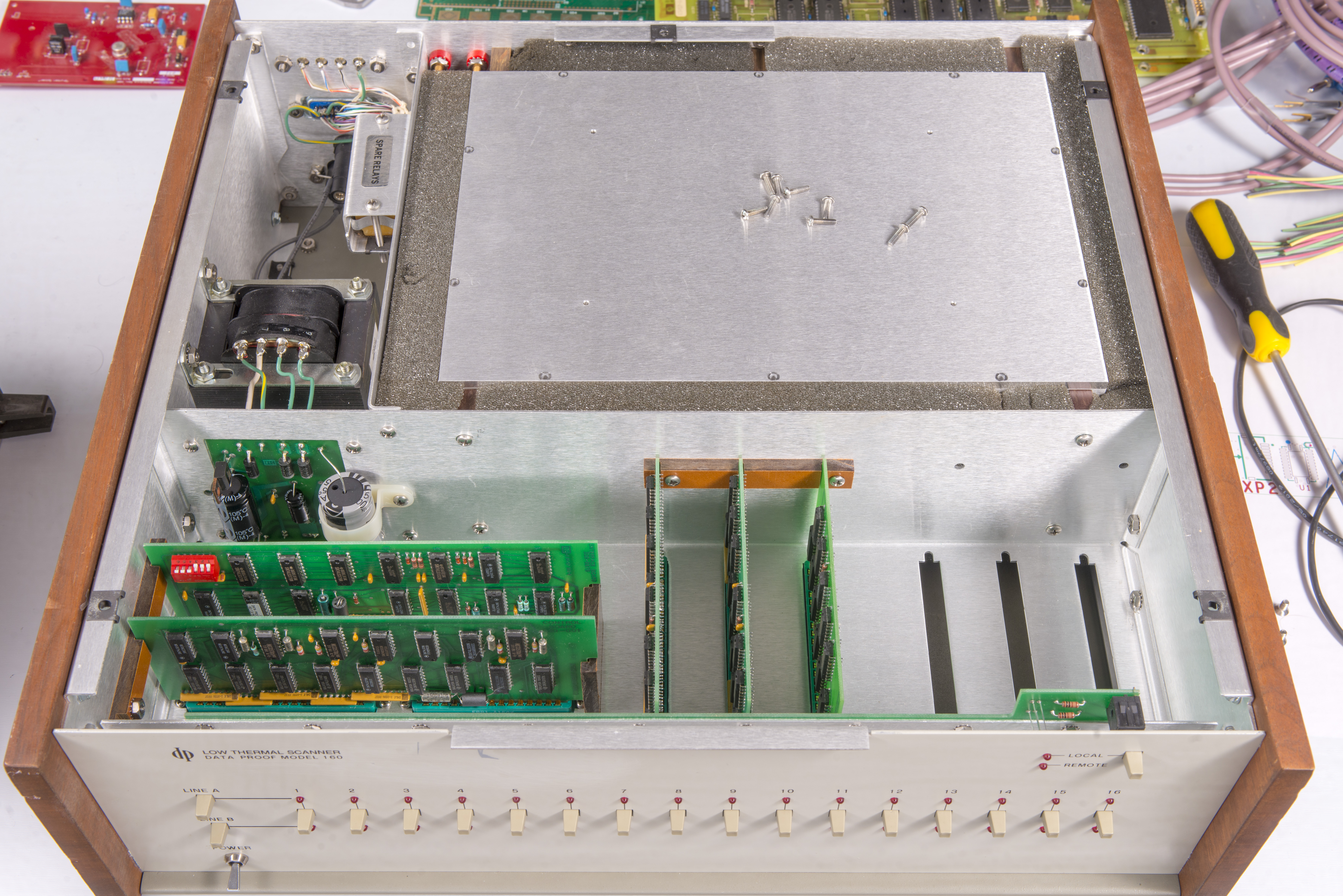
Let’s see what is inside of this switch box. Disassembly is simple, just remove screws holding covers in place and spacey interior is available for review.
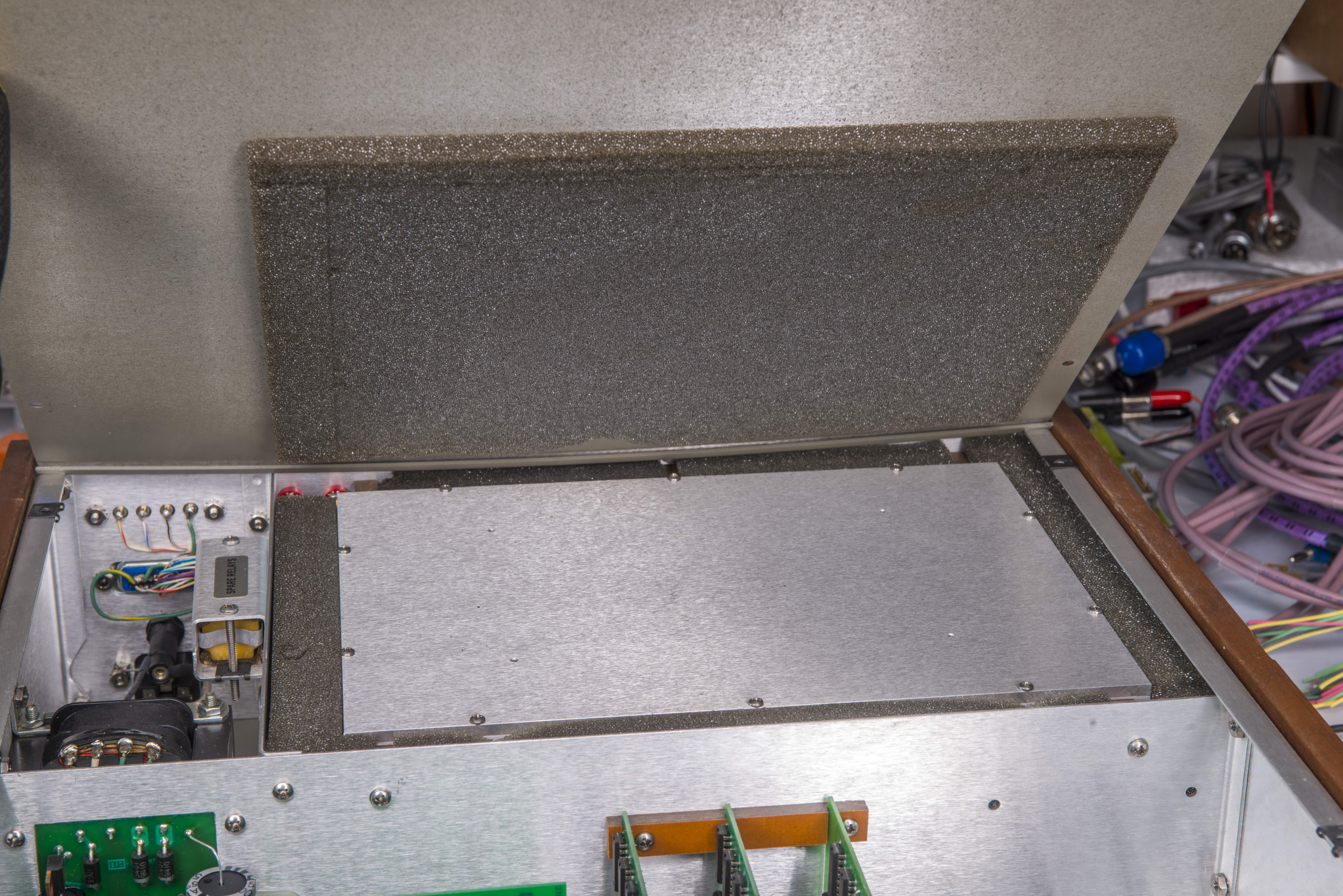
Immediately you can spot isothermal chamber where all the switching hardware reside, surrounded by foam to dampen temperature gradients and airflow around critical components inside.

Image 5: Isothermal chamber covered
Sensitive box with switches shielded by metal cage with two covers on top and bottom.

Images 6-7: Switch chamber covers
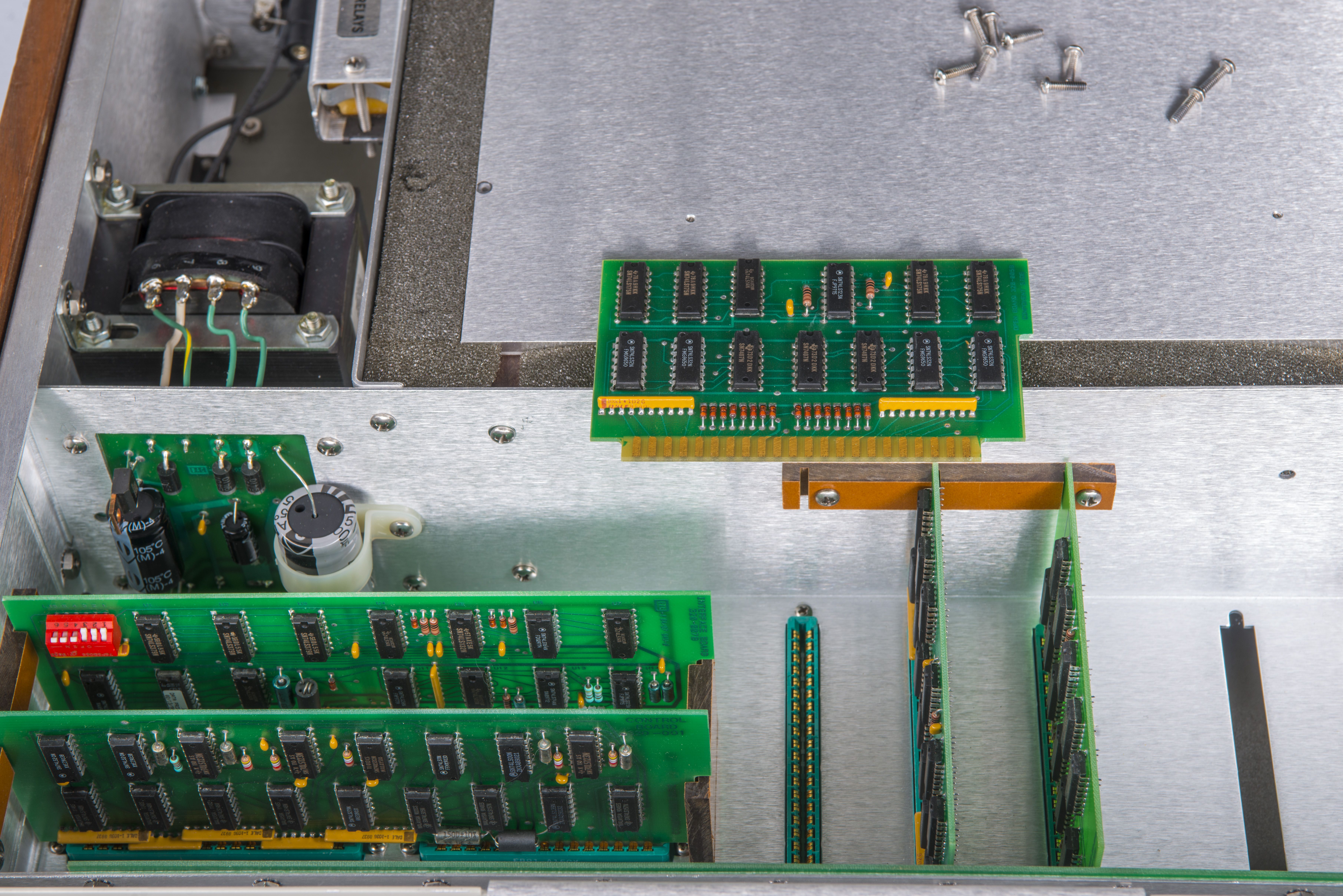
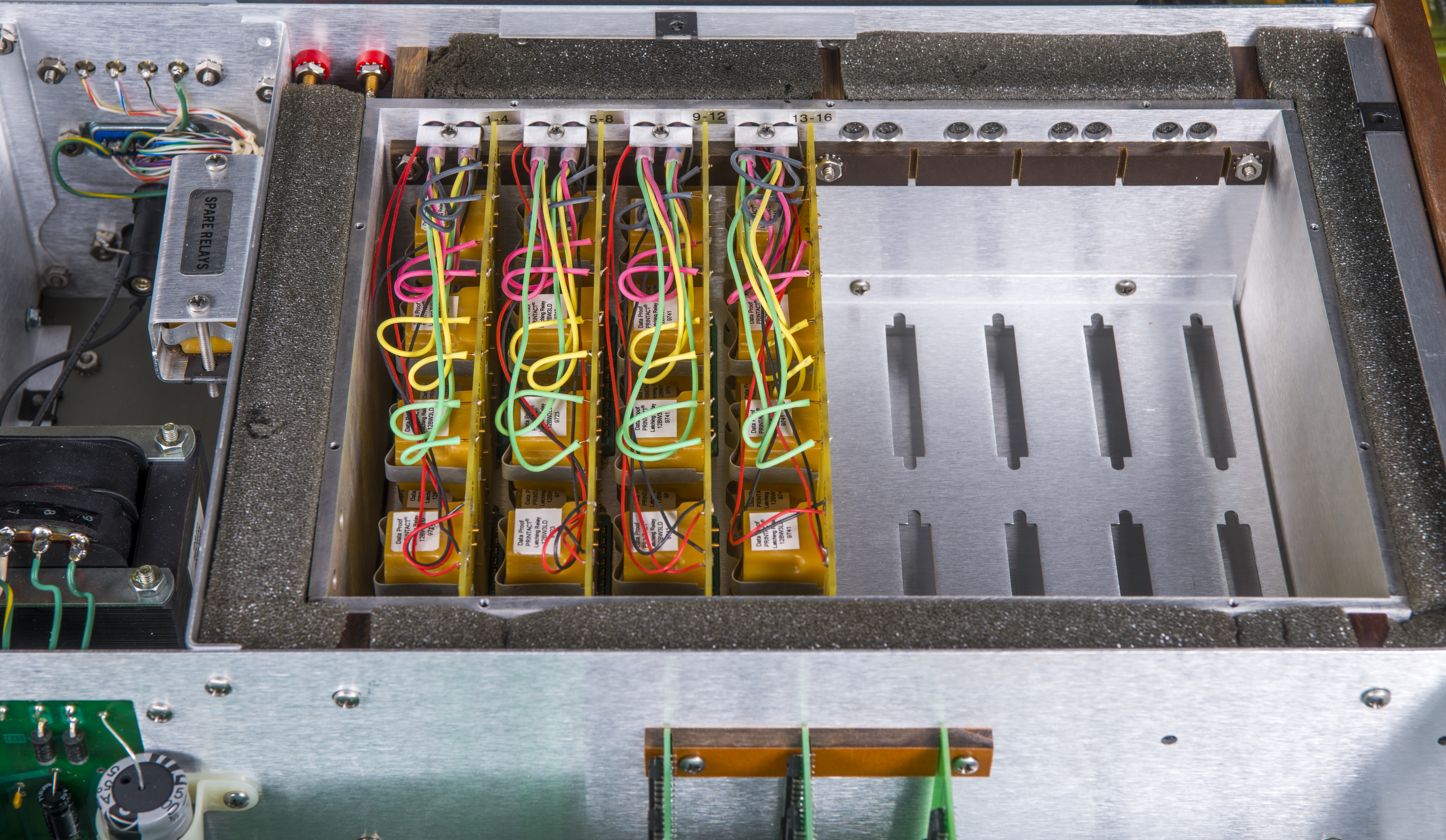
Removing metal shield cover from top allow to see inner boards:

Image 8: Exposed compartments of switch unit
Bottom side feature just tidy wiring to connectors and nothing else:

Image 9: Bottom wiring side overview
Binding posts version have wiring soldered directly to posts, without much special precautions.
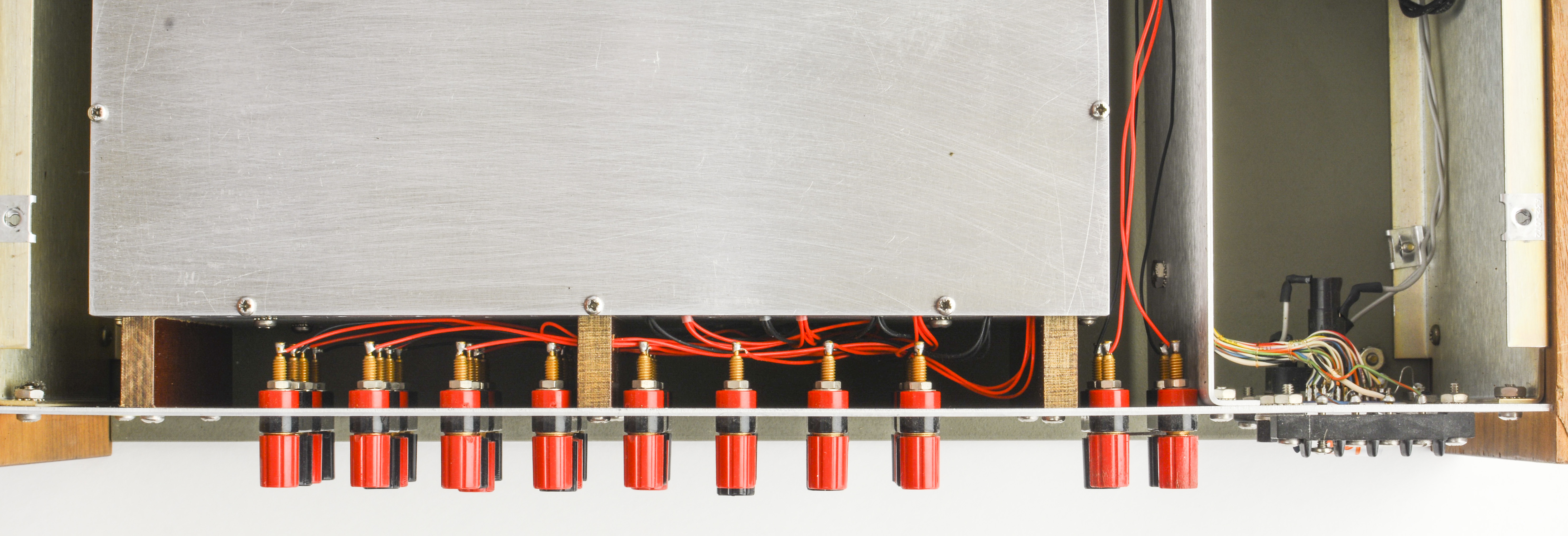
Image 10: Binding posts wiring
Worth to note few extra spare relays in special comparment available for servicing (nice touch, considering unique relay construction) and some protection switches?

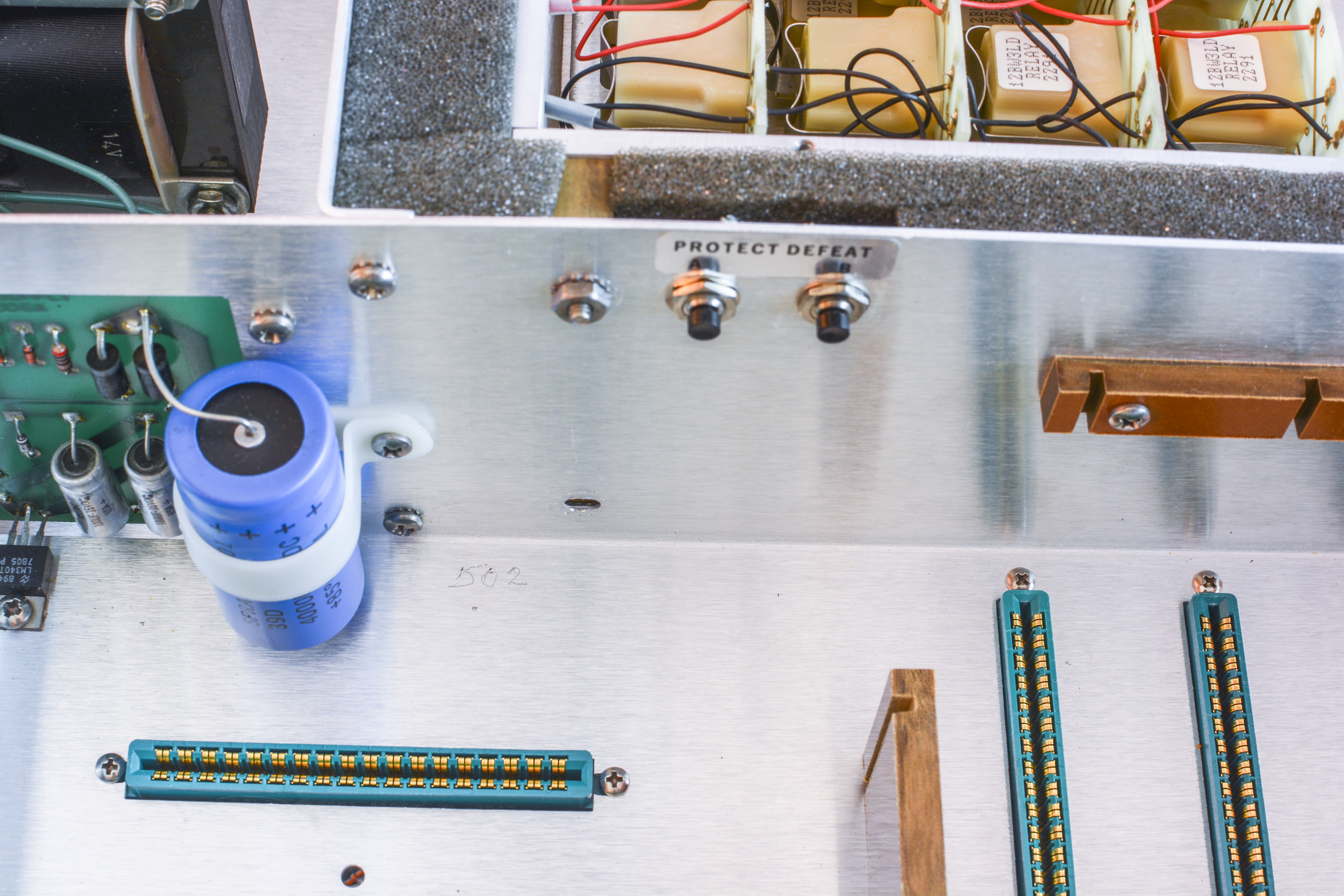
Images 11-12: Spare relays holder and internal switches
Power supply filtering and linear regulator mounted near mains transformer to serve voltage across digital control boards and relay drivers. The power supply has two outputs. There is a 5 VDC output for the digital logic and a 14.4 VDC output for the relays. The relay power supply cannot supply enough current to perform rapid switching of the relays. This is by design for the protection circuitry. It is recommended that a 200 ms delay be used in between switching of any positions.
The newer 160B/320B models of these scanners use an external power supply most likely to reduce added heat inside the scanner.
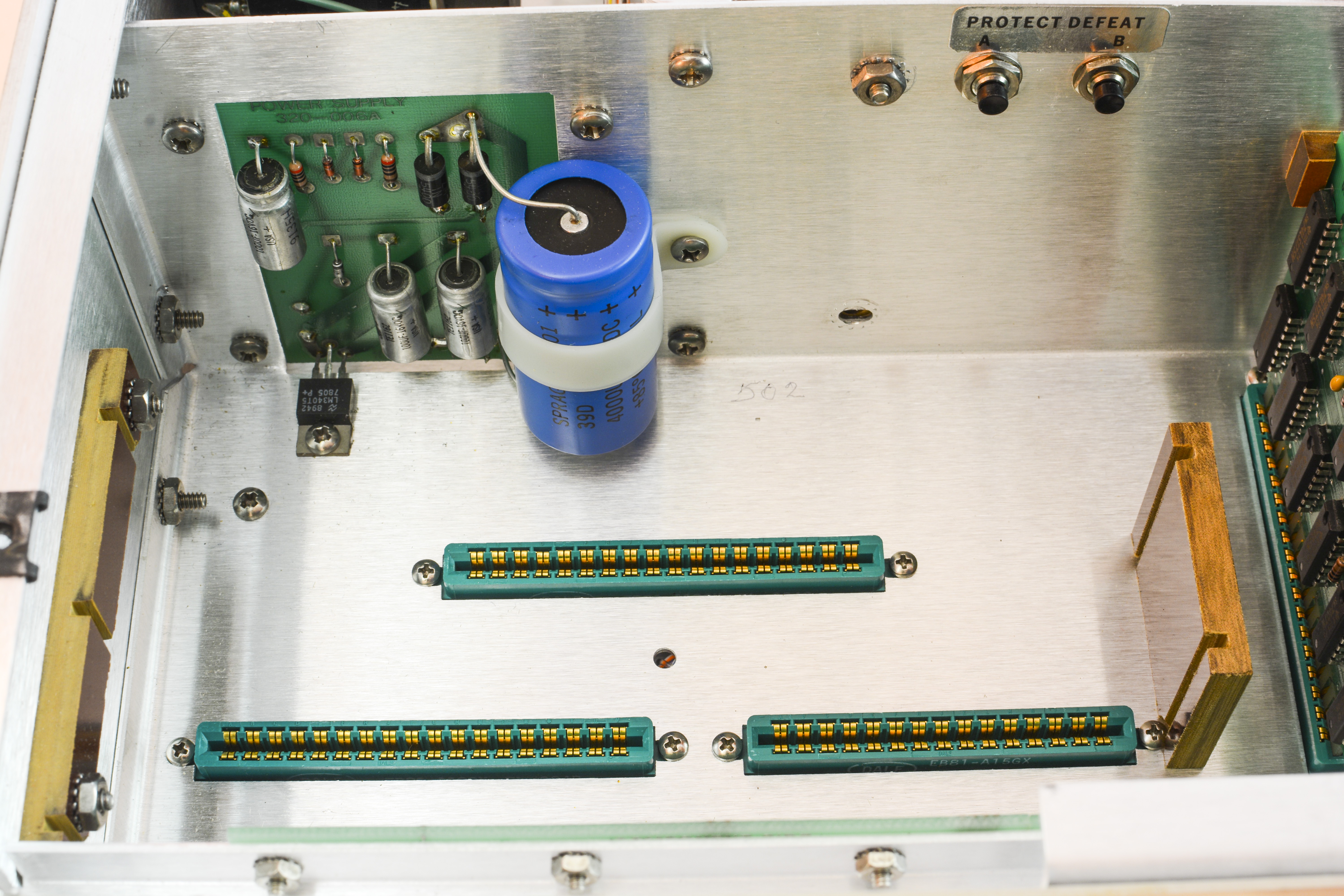
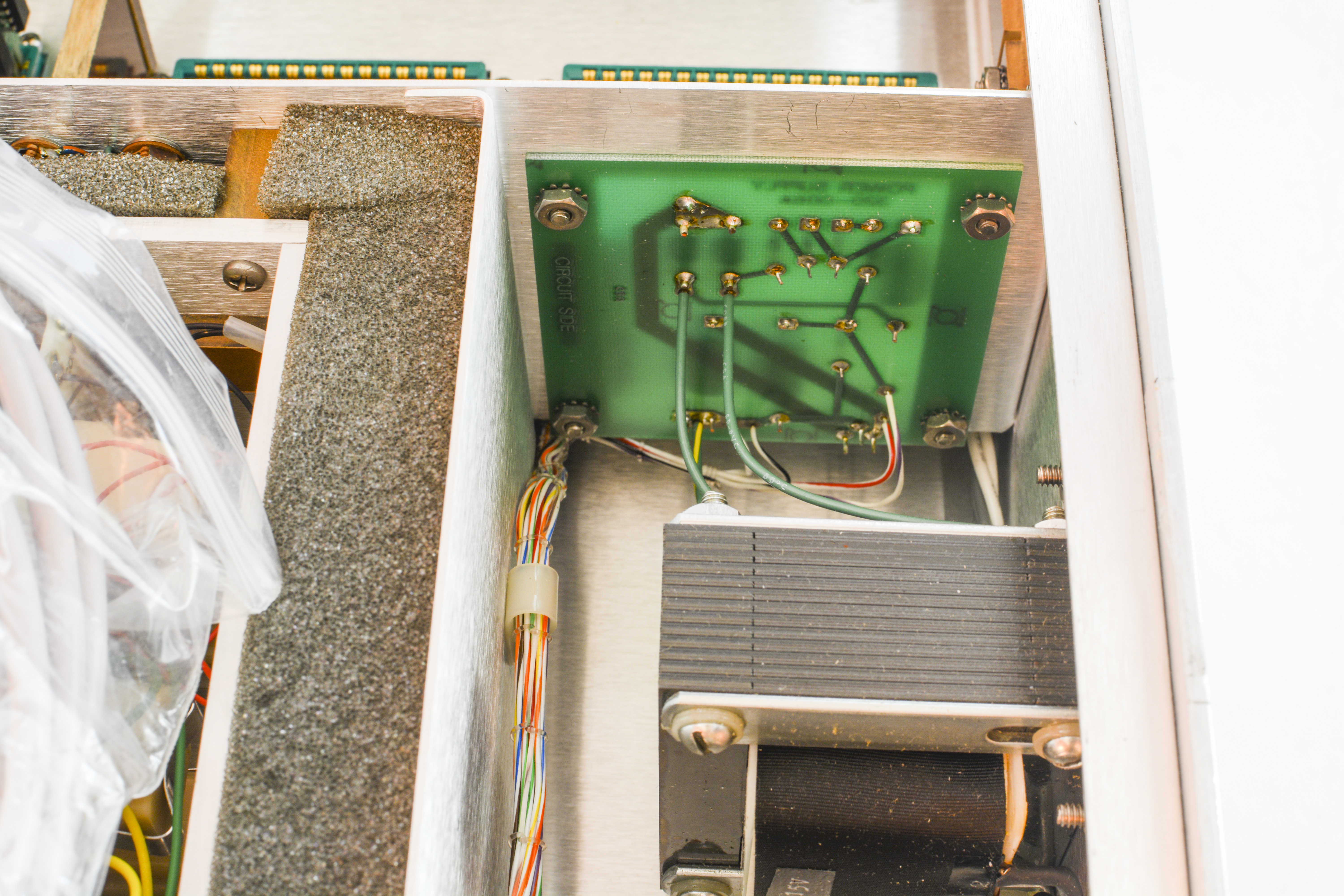
Images 13-14: Power supply regulator board
Front panel switches and indicator LEDs are mounted on four PCBAs. Each board routed to own edge connector, fixed by pair of screws.
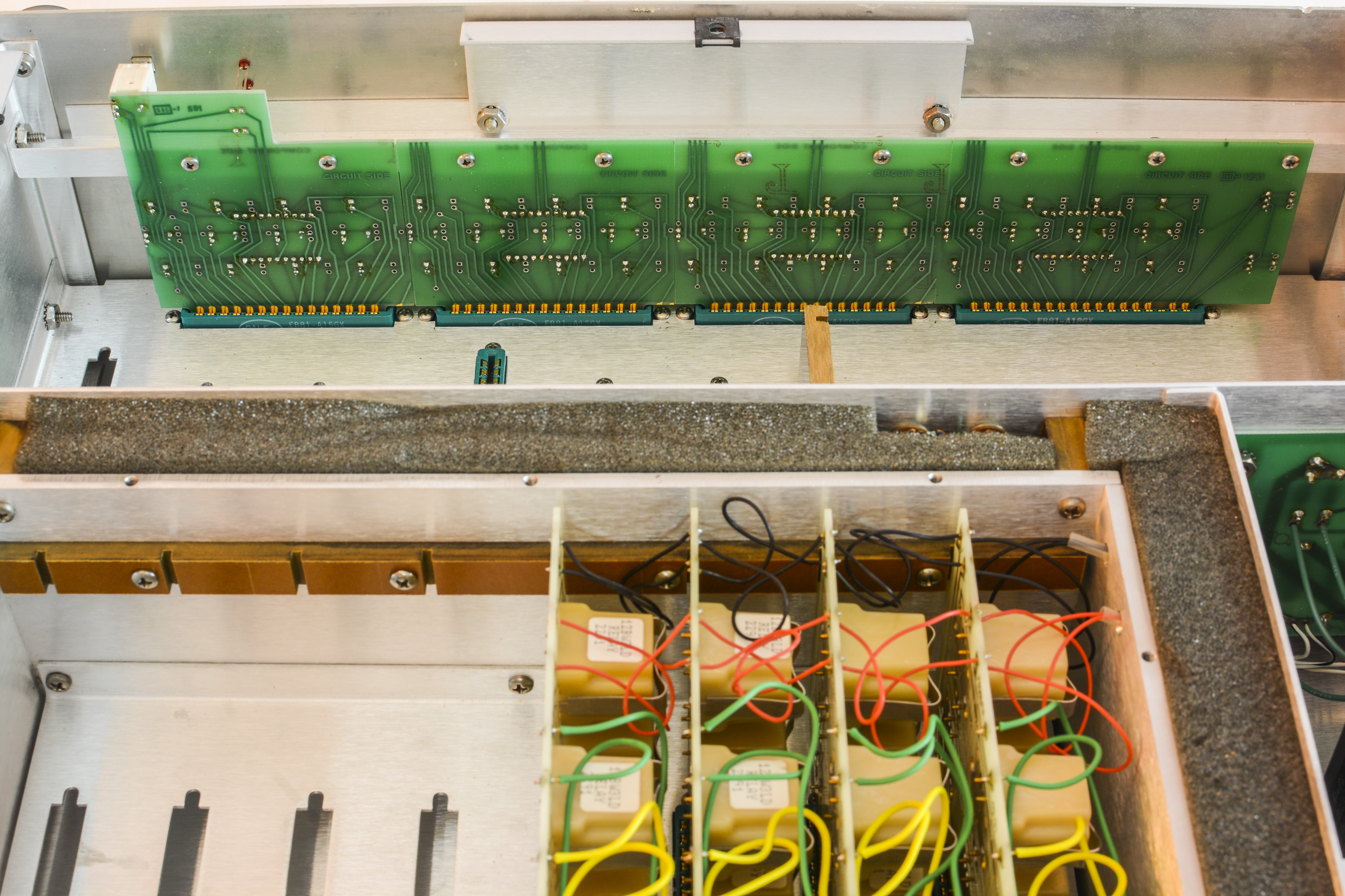
Image 15: Front PCB
There are no less than nine screws to keep front panel boards secure inplace.
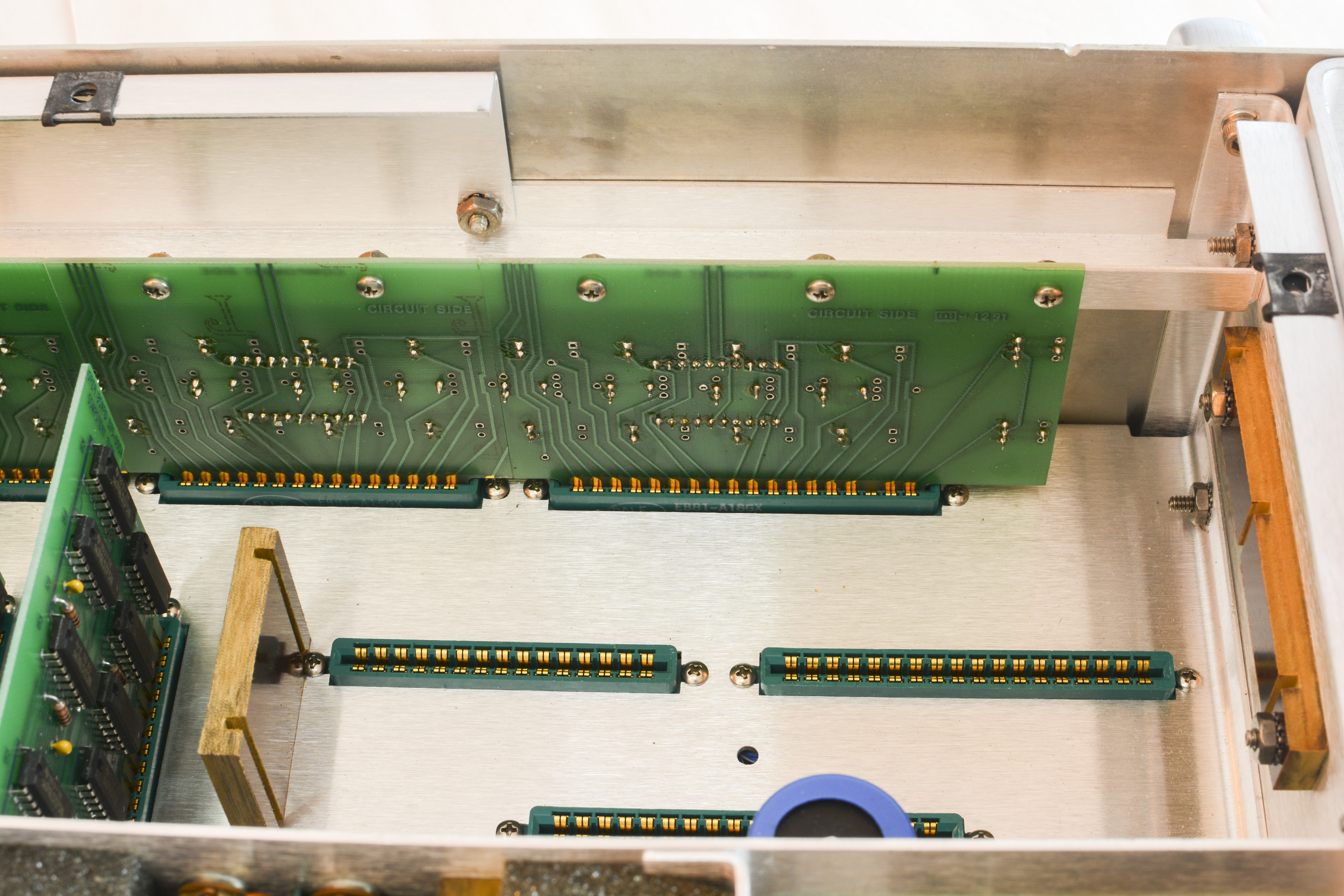
Image 16: Front panel back
GPIB interface connector is wired directly to terminal block and interface board.
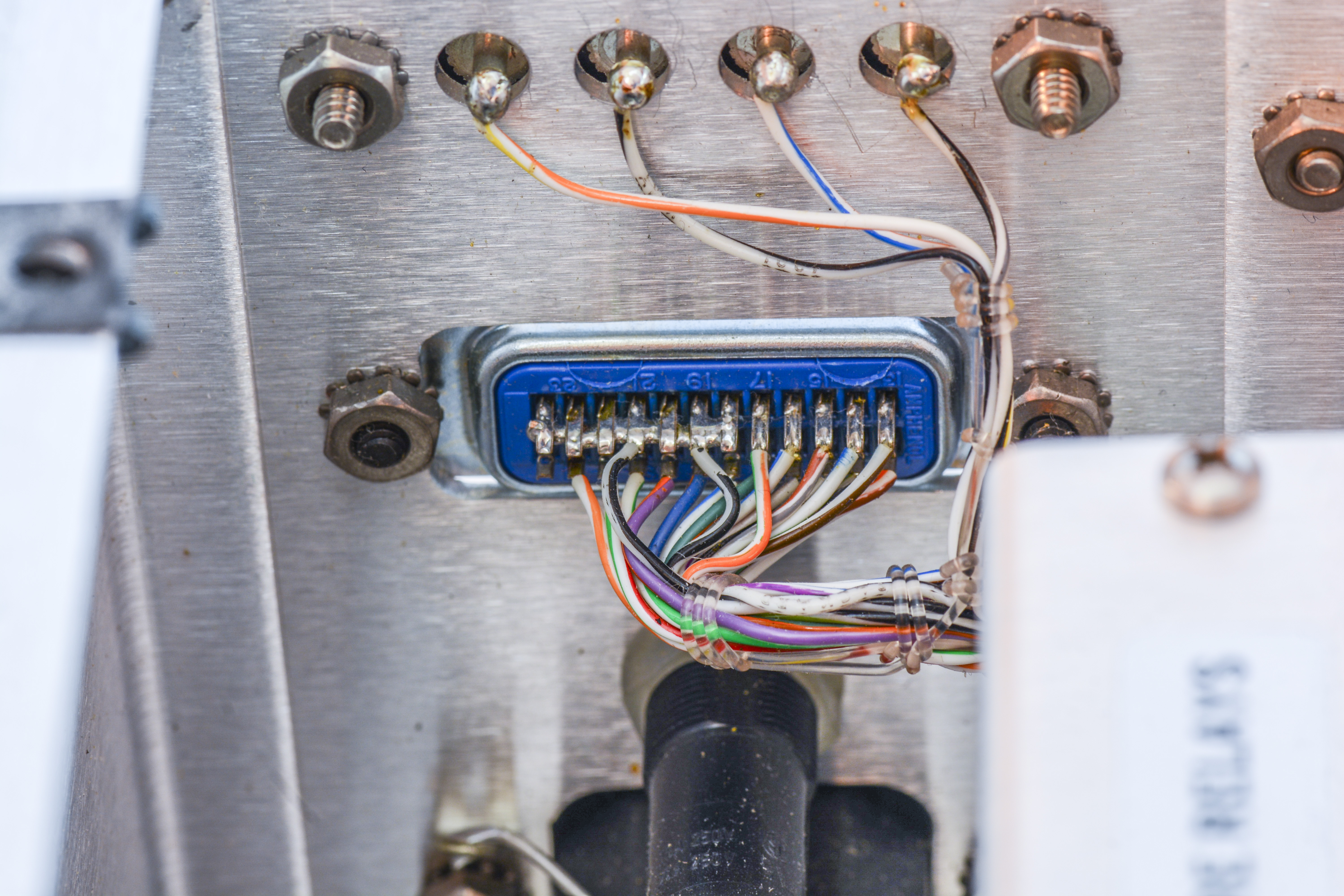
Image 17: GPIB port cable harness
Few extra shots:

Images 18-19: Switch mapping and linear regulator close-up
Internal control boards
Interface board 1
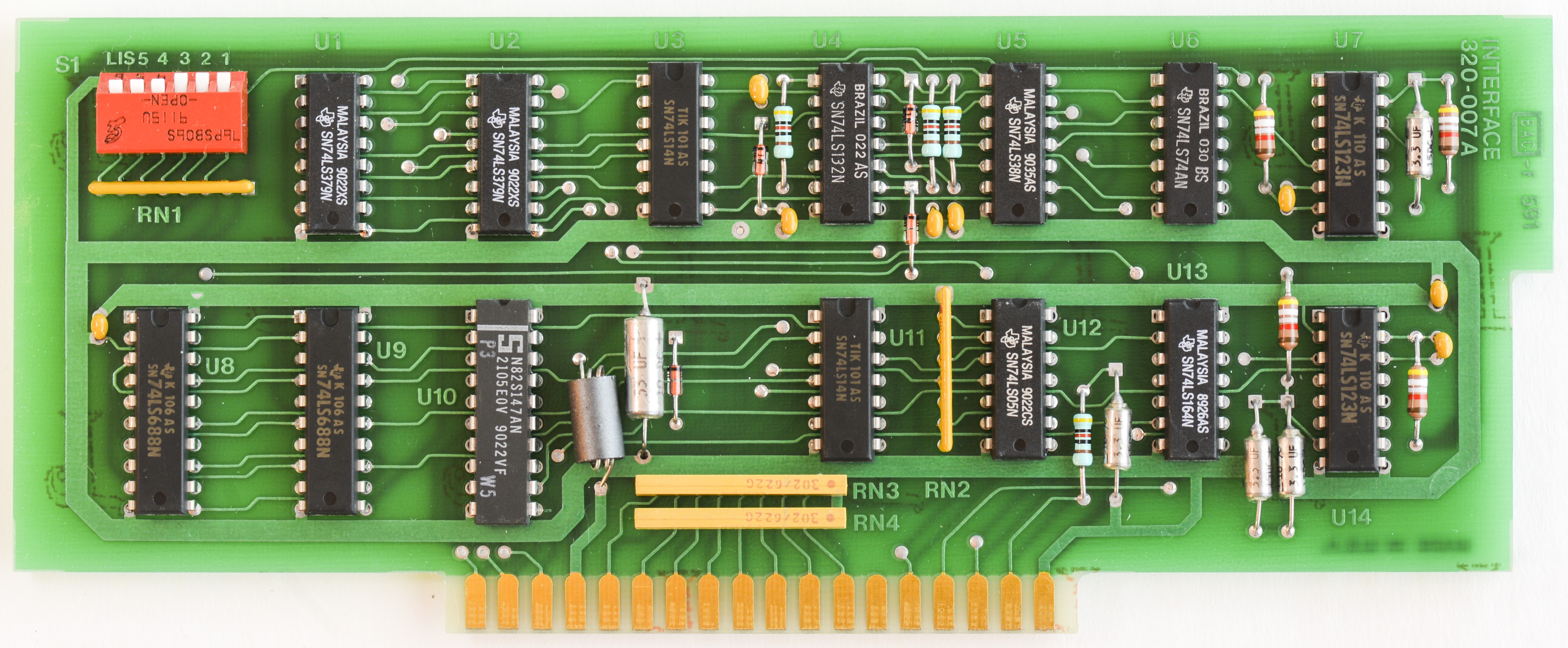
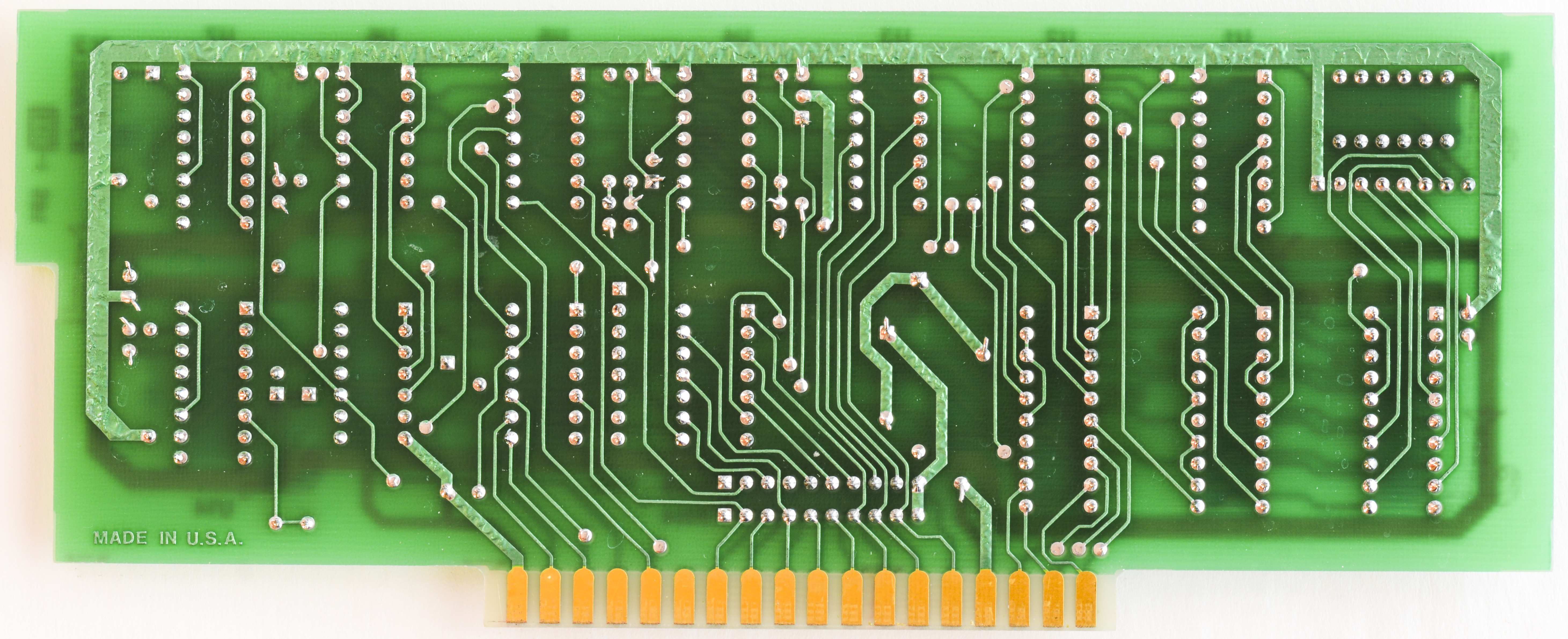
Older PCB Revision, manufactured in 1984 have some reworks and jump wires, as well as logic 7432 IC on the bottom side.
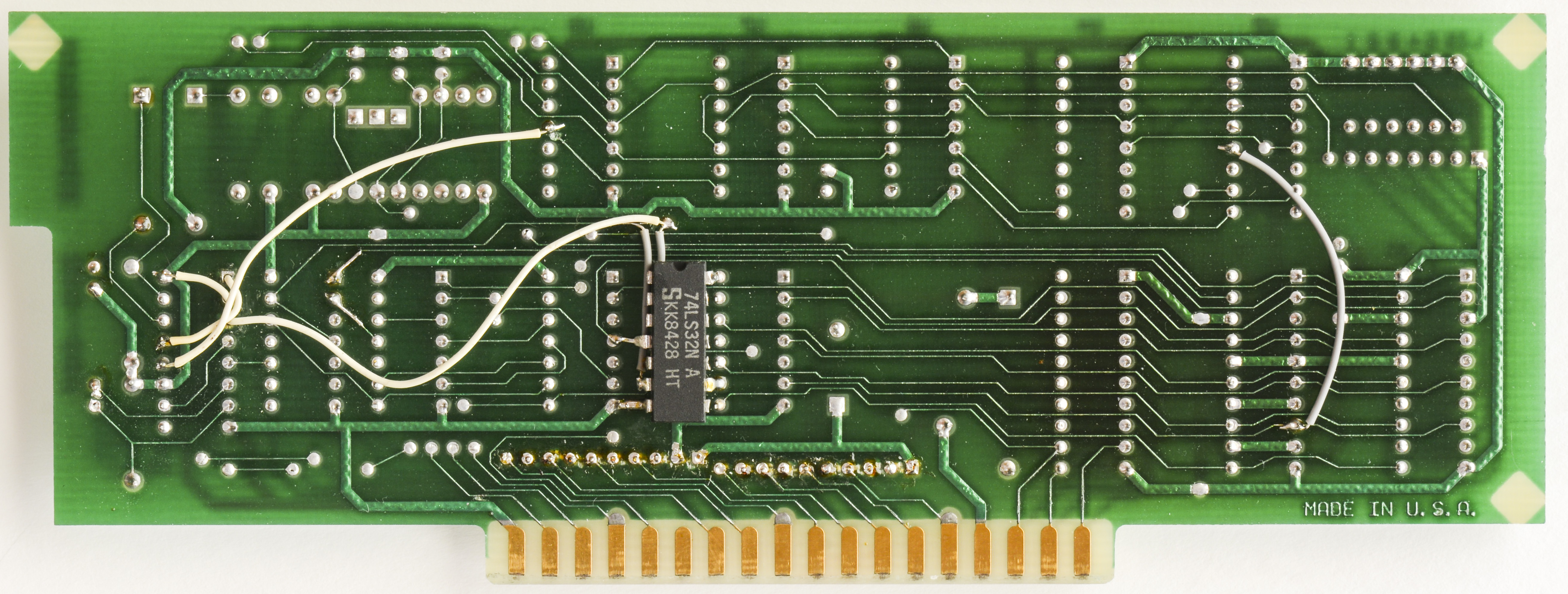
Images 24-25: Old revision of interface PCBA
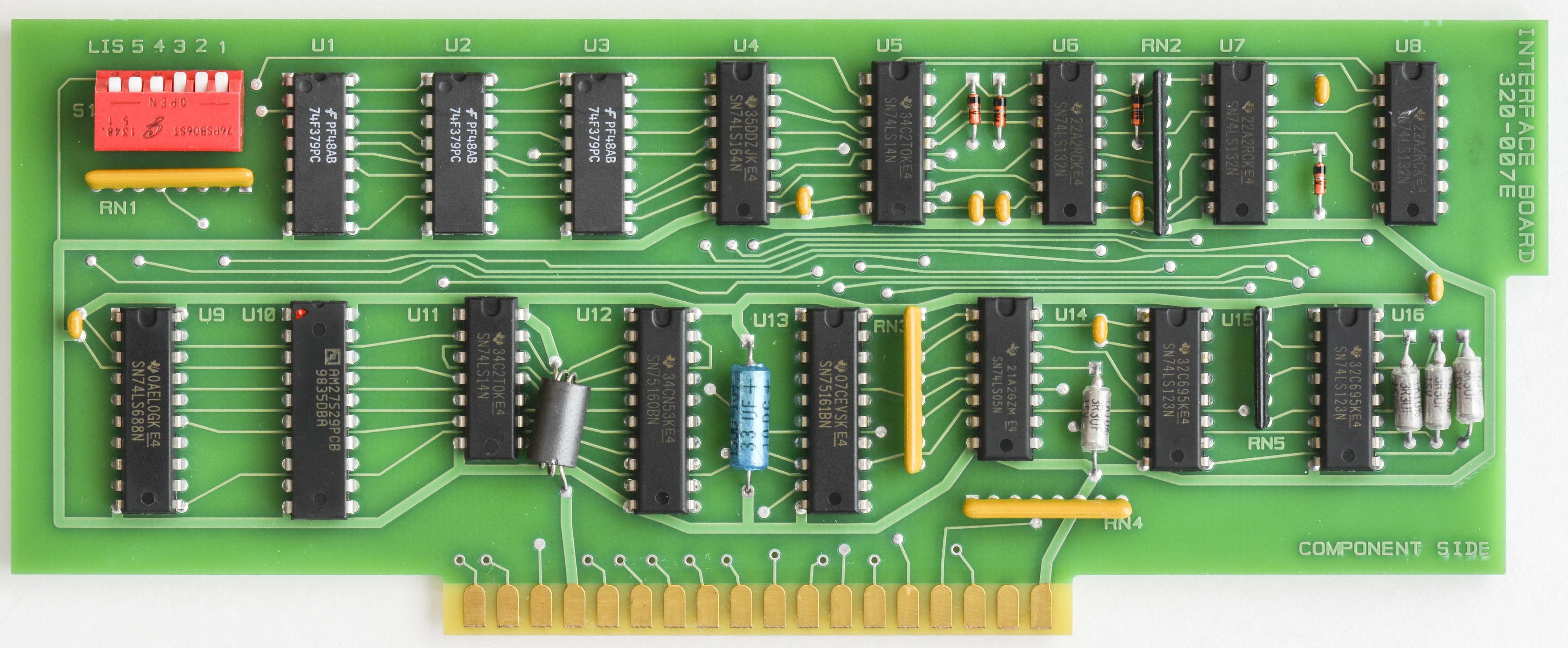
Data Proof acknowledges that there were some issues with older interface boards. A replacement was purchased and its Rev level is E. Their website lists the newer version as D.
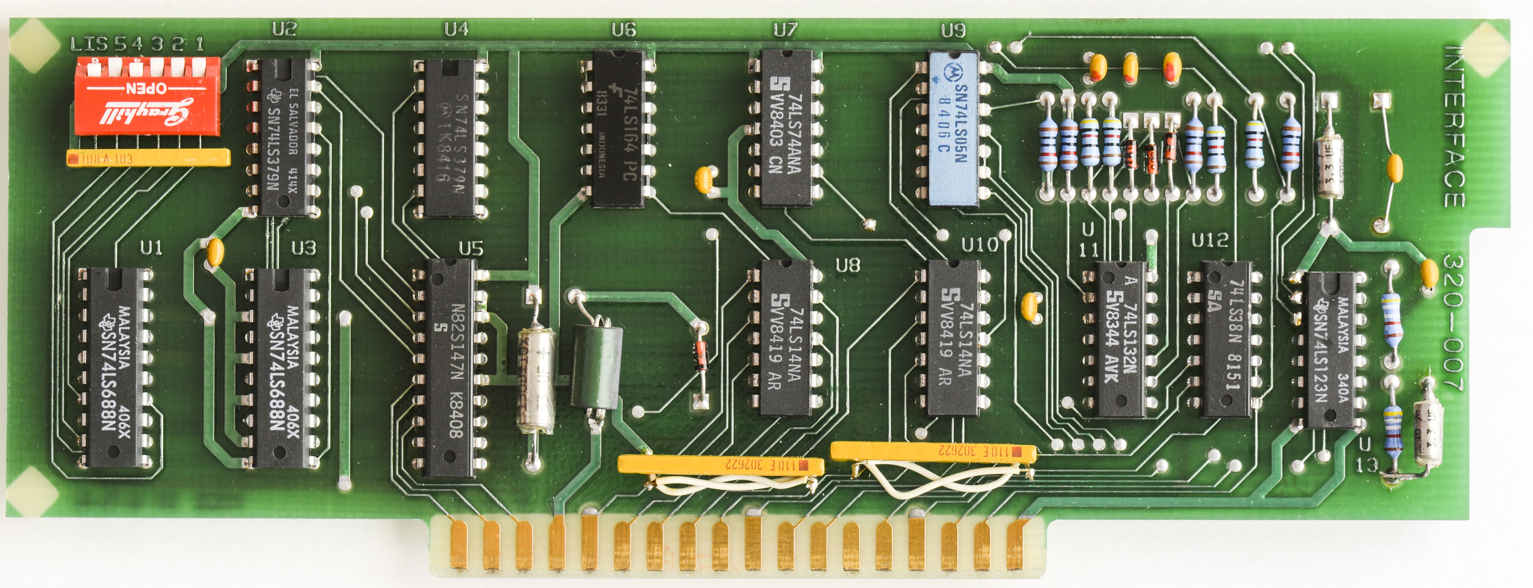
Interface board 3
Images 20-21: New revision of interface PCBA
The scanner communicates with the outside world using a very basic hard-logic GPIB connection. The board is a simple interface that only accepts incoming commands.
There was an issue with programming my scanner. I had to add a space after the string to get the relays to operate. Instead of “A01” I send “A01\n”.
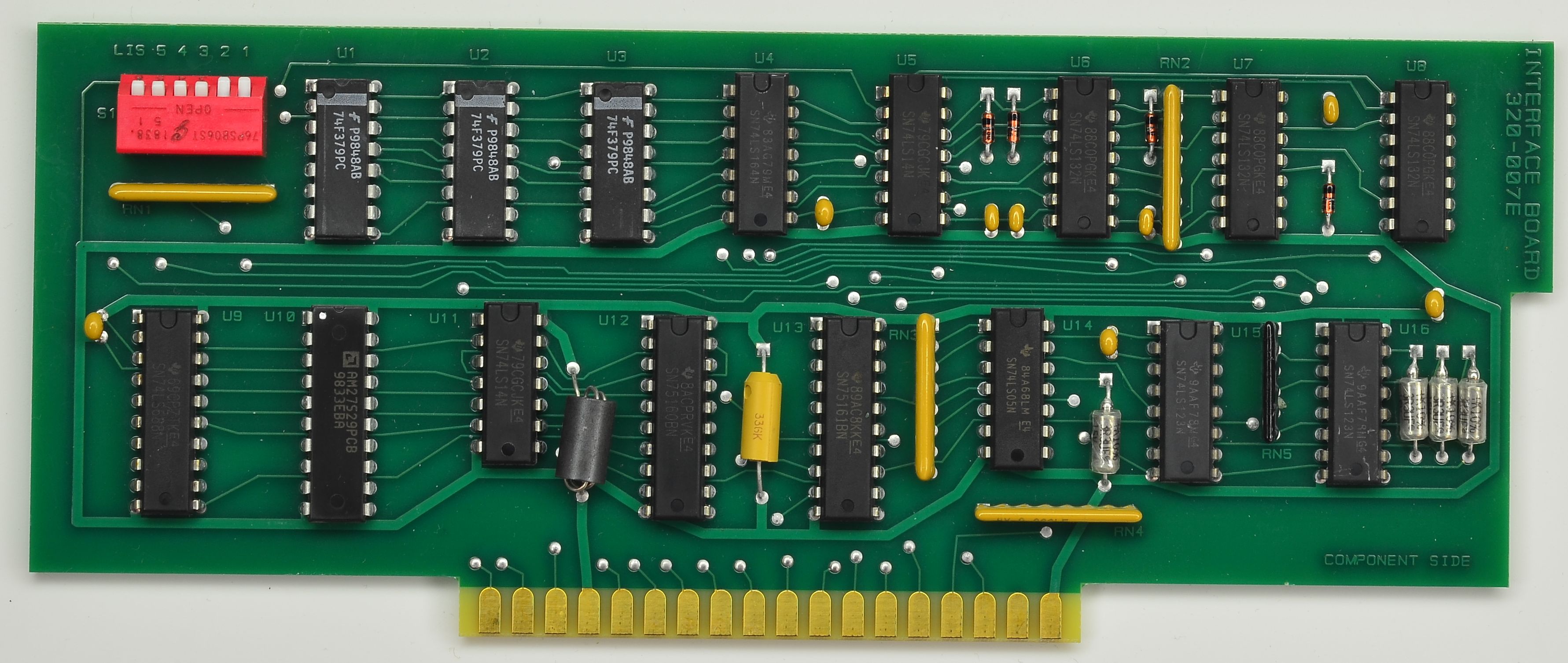
Interface board 2

Images 22-23: Revision E of interface PCBA
Additional photos of GPIB board Rev E from 2020.
Open relay driver board

Images 26-27: Open relay control board for switch drive
Close relay driver board

Images 28-29: Close relay control board for switch drive
Control board

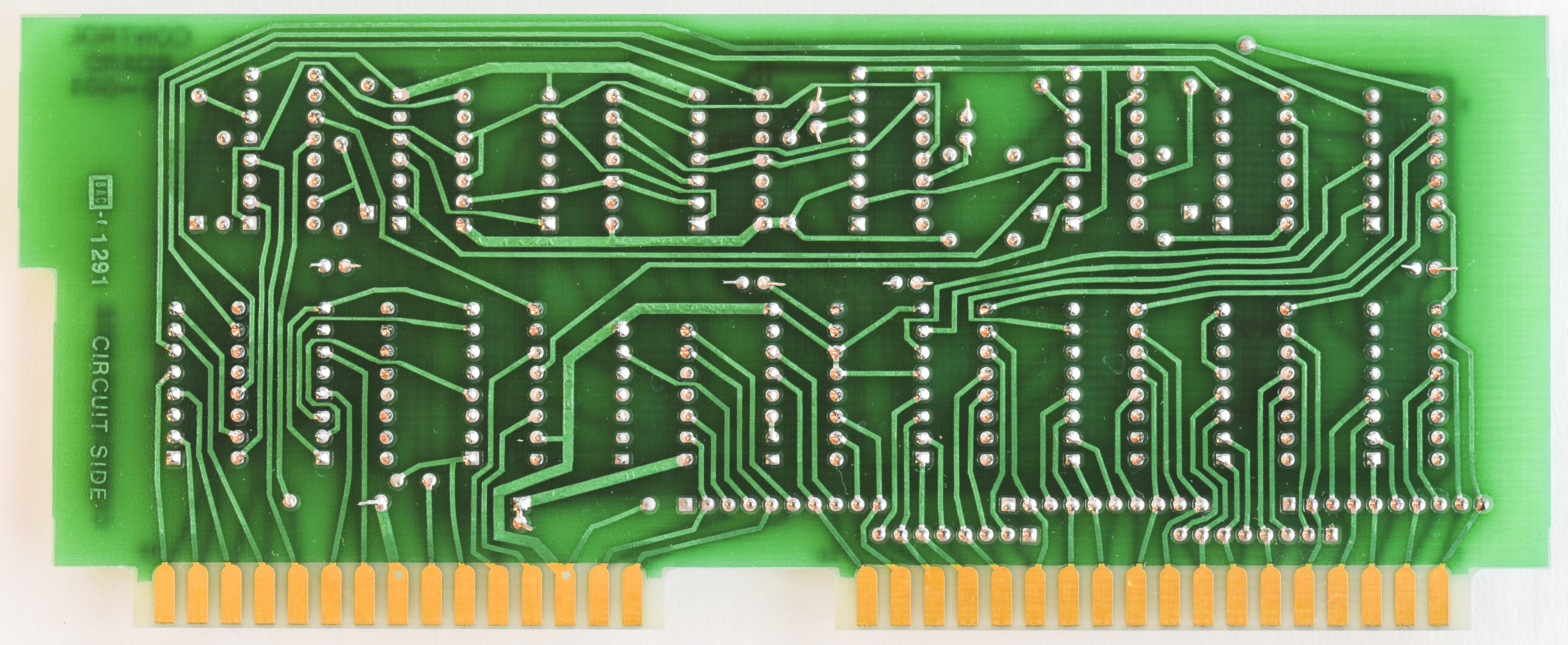
Images 30-31: Control logic assembly
Channel switch boards
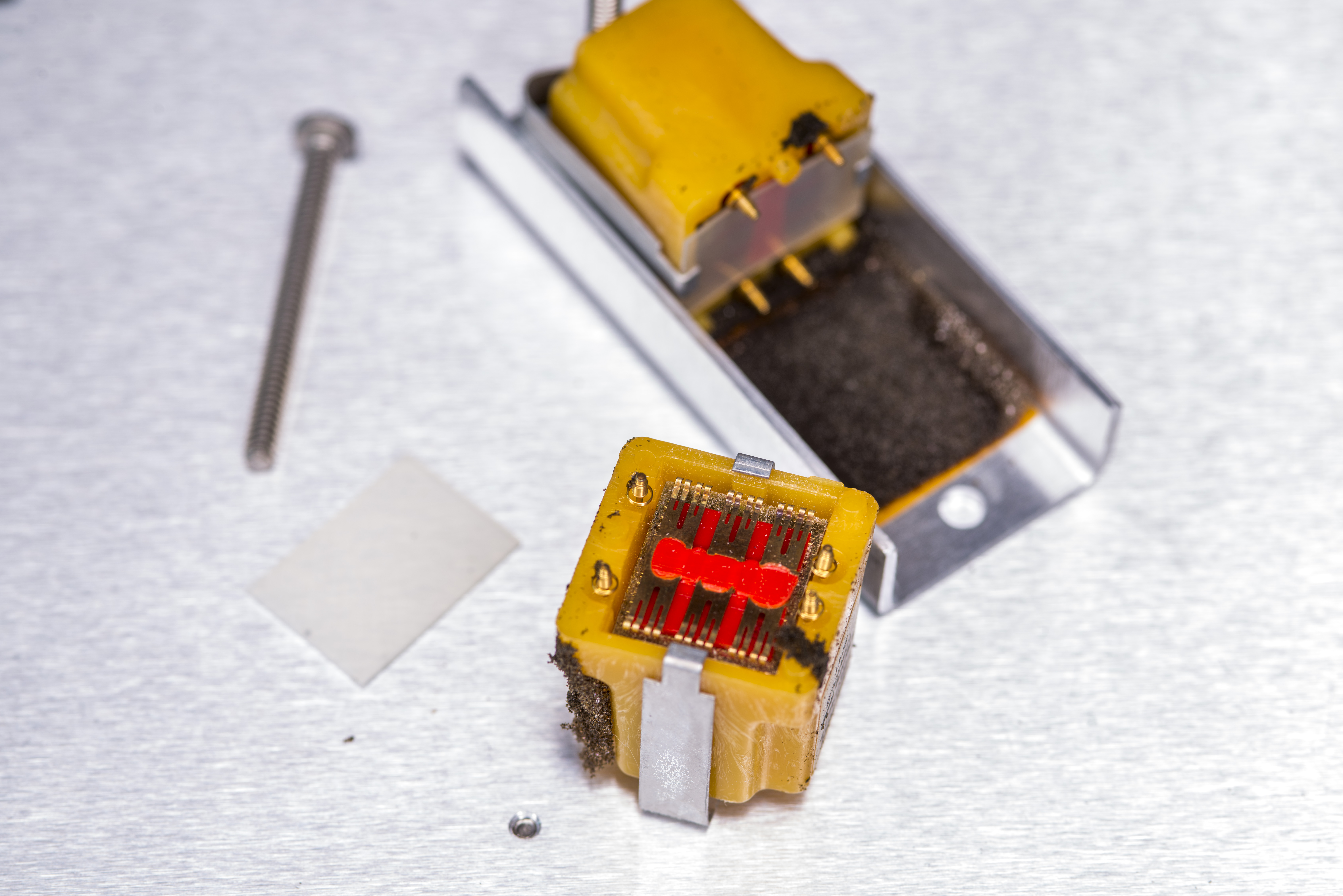
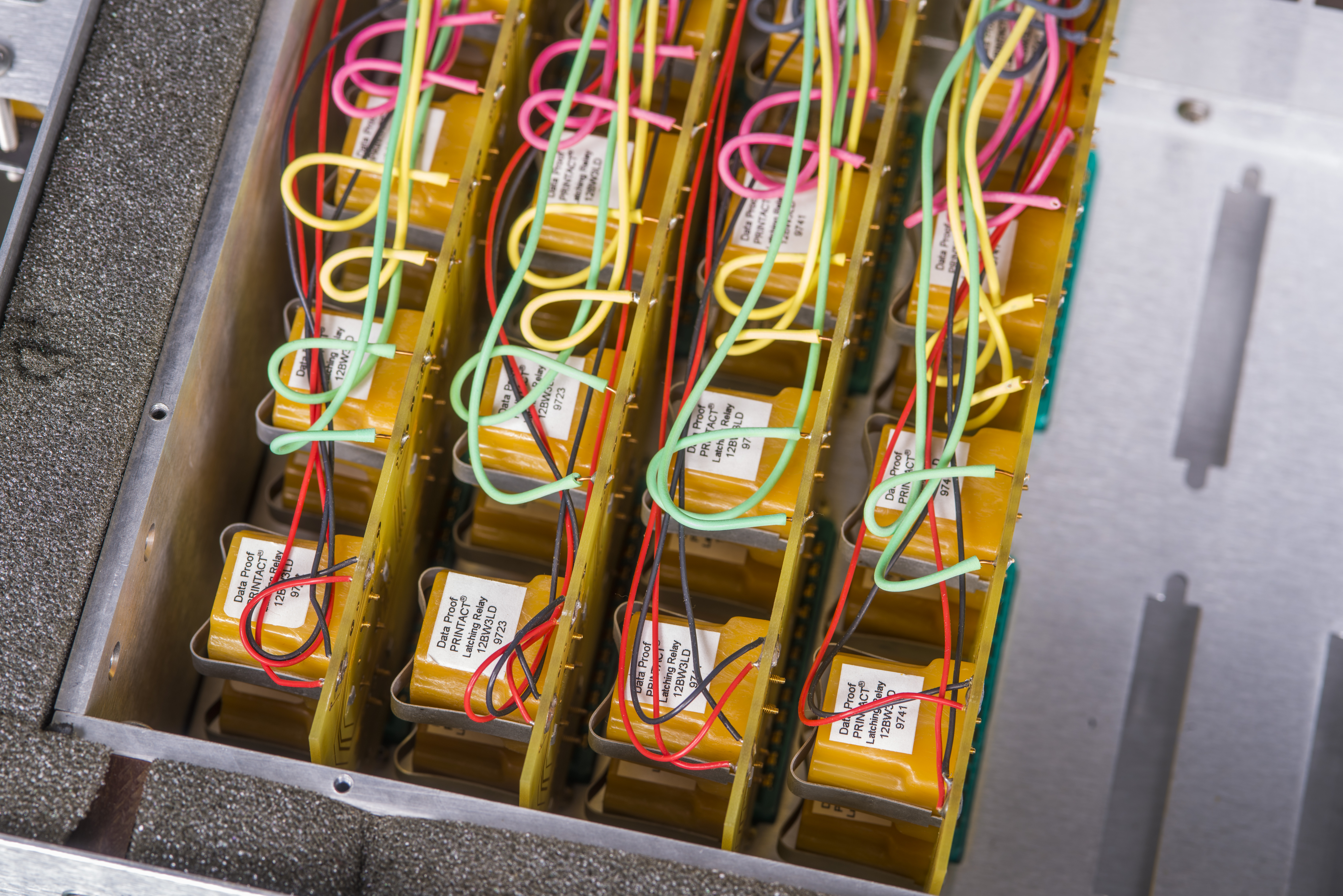
The heart of the scanner is based on a special relay that has no stationary contacts. The relay was designed to use the traces of a pcb as its contacts. I believe the relays had their origin in older POTS switches but cannot confirm this is true. The model of the relay is a PRINTACT Executone 12BW3LD. This model is a dual latching style and both sets of coil contacts can be seen from the bottom with small springs wound around them. The contact configuration is 3PDT but are not like a typical 3PDT relay.
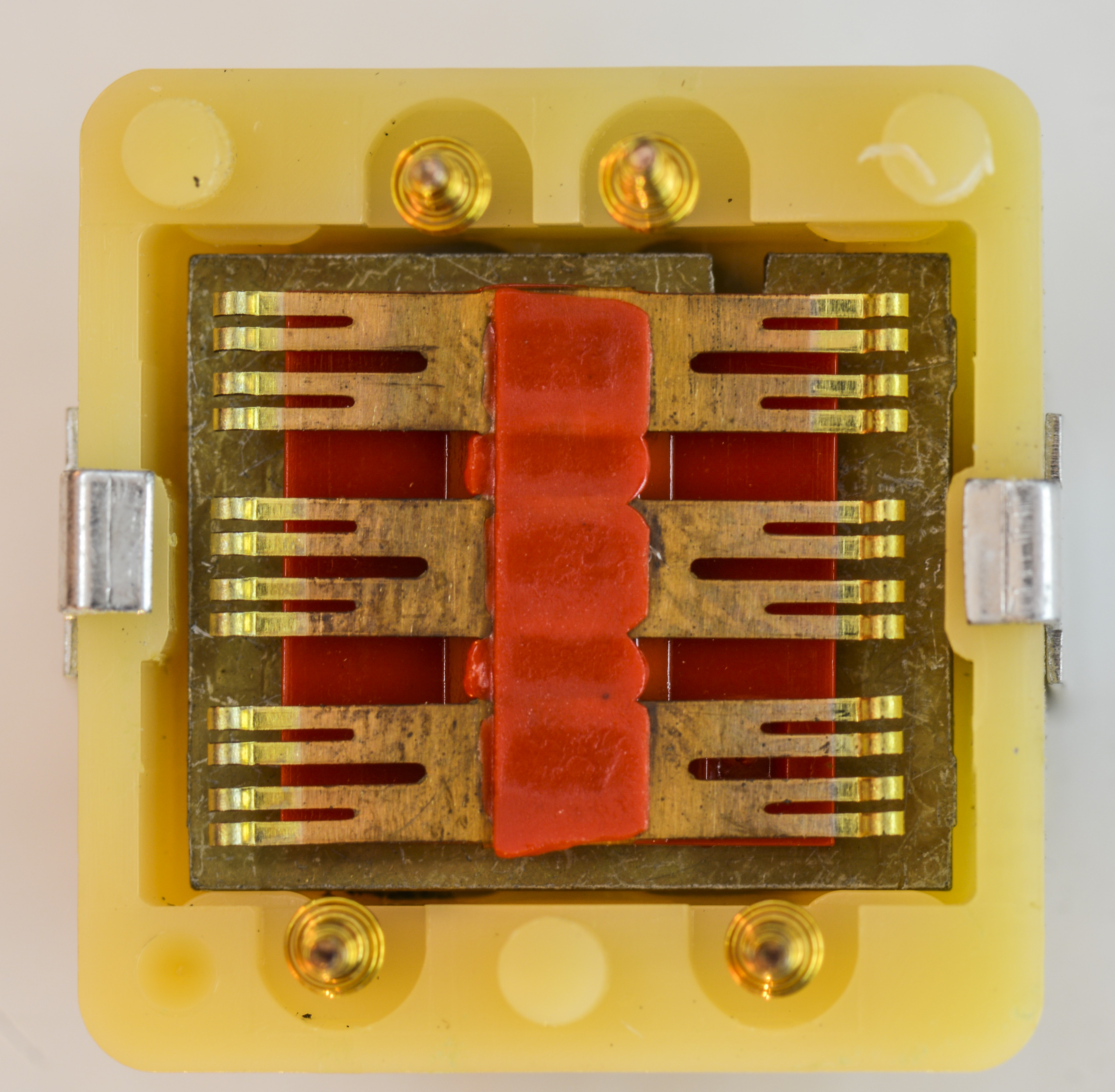
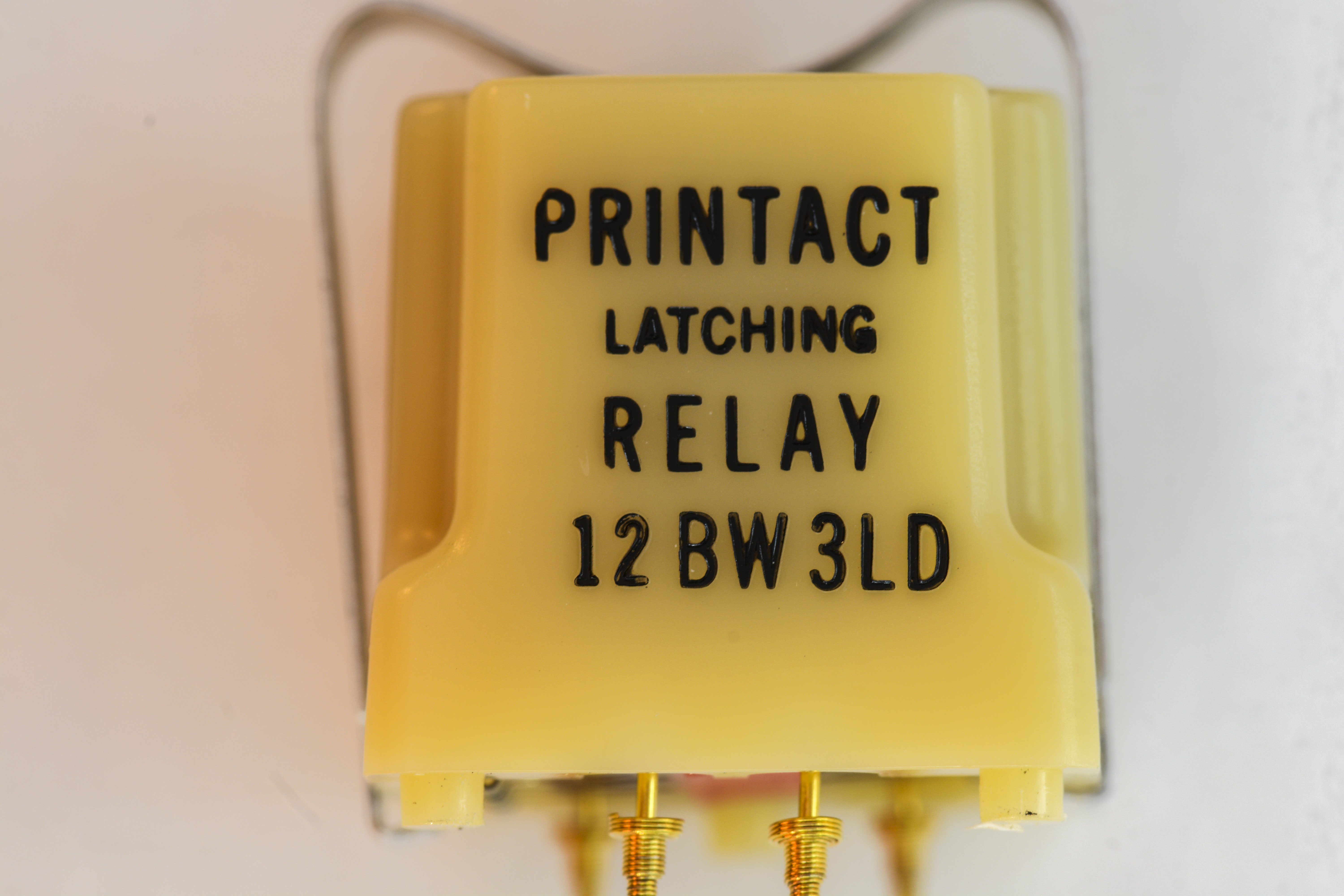
Images 32-33: Custom relay brush contact and label
The contacts do not have a common connection between positions. This allows the positive and negative inputs of each reference to become disconnected when not in use. The relays are manufactured by Data Proof and are still in use in their guarded scanners while the standard version uses newer DPDT relays that are custom made according to the manual.
Thanks to the Patent number, we can study some of construction aspects of these relays in related US2881365 Patent.
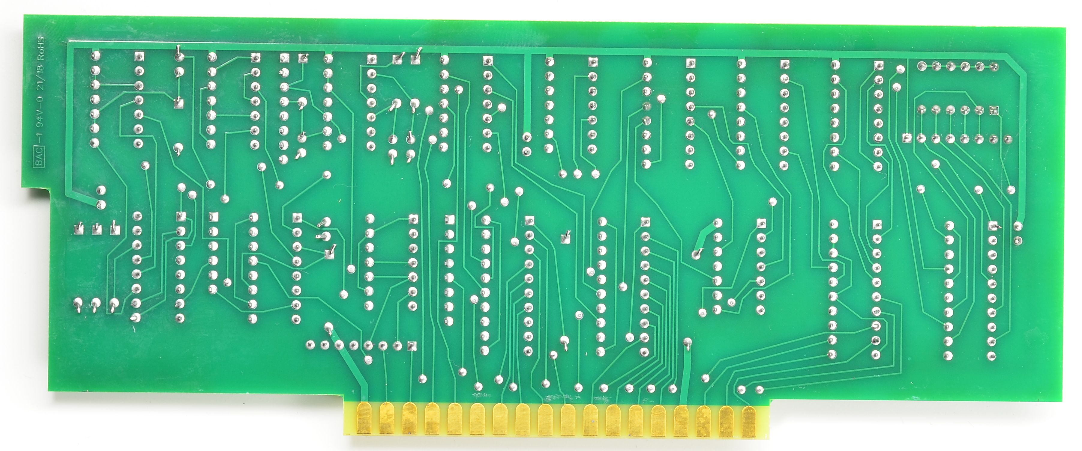
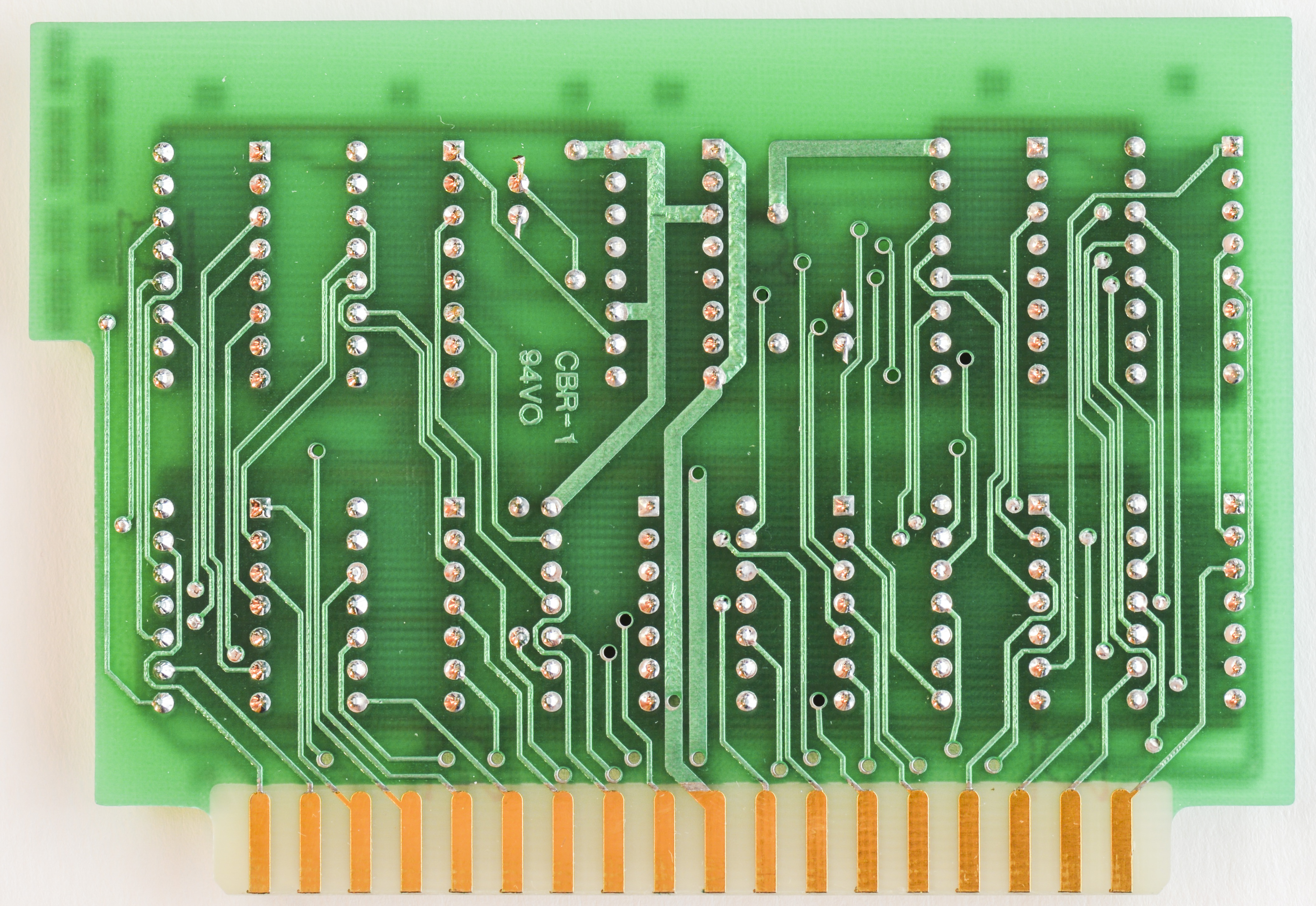
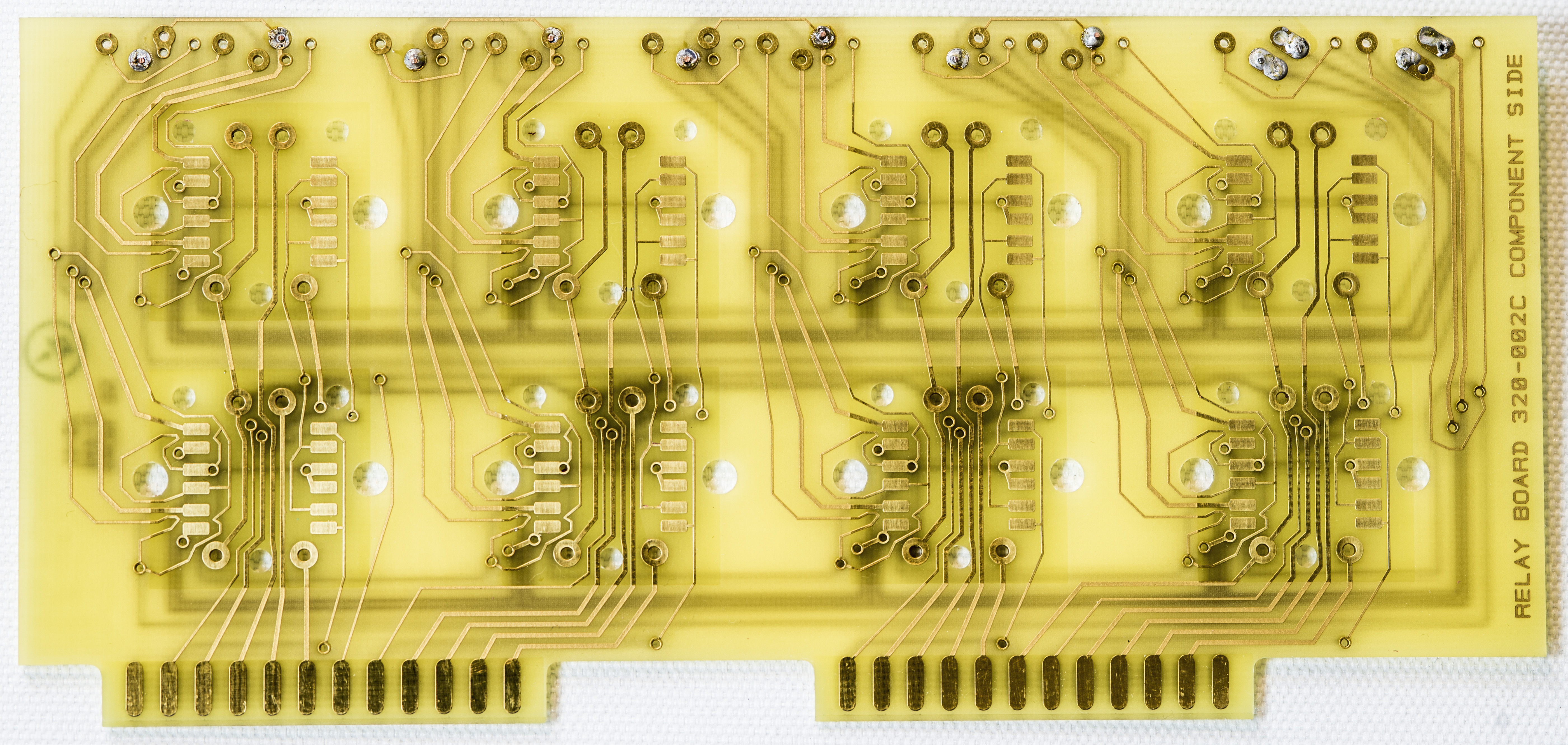
For better clarity below is bare PCB without relays installed.
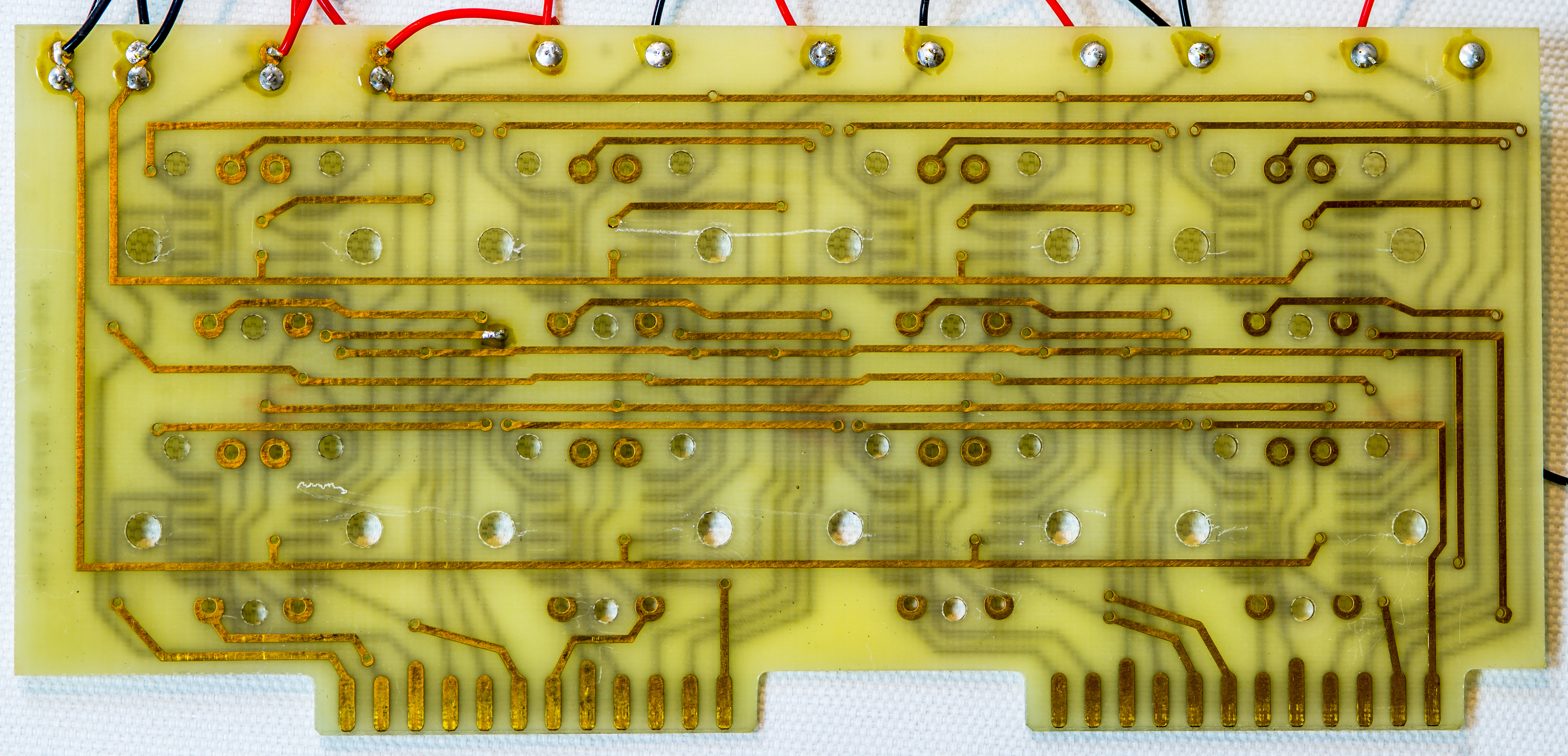
These relays are self-cleaning, so it is recommended to exercise them a few times if they haven’t been used for a while. Also no soldering used on switching board, as relays are pushed to PCB by spring clips. All signal routing and interconnection done by copper traces on PCB, which is also plated with gold to avoid corrosion and oxidation. This avoids using special, often toxic, soldering alloys in goal to keep thermal EMF low as possible.

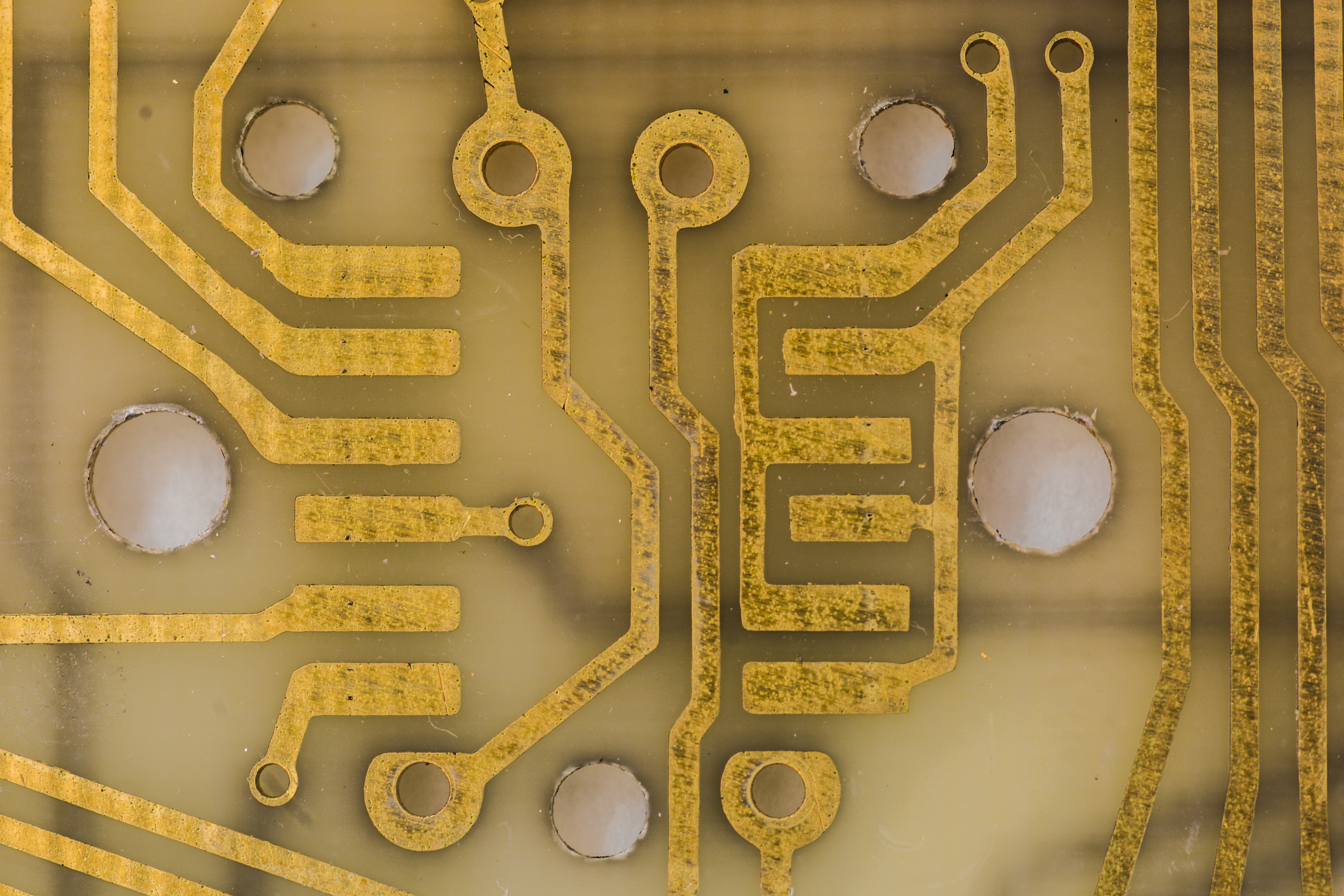
Images 34-35: Switch contacts on PCB and close-up
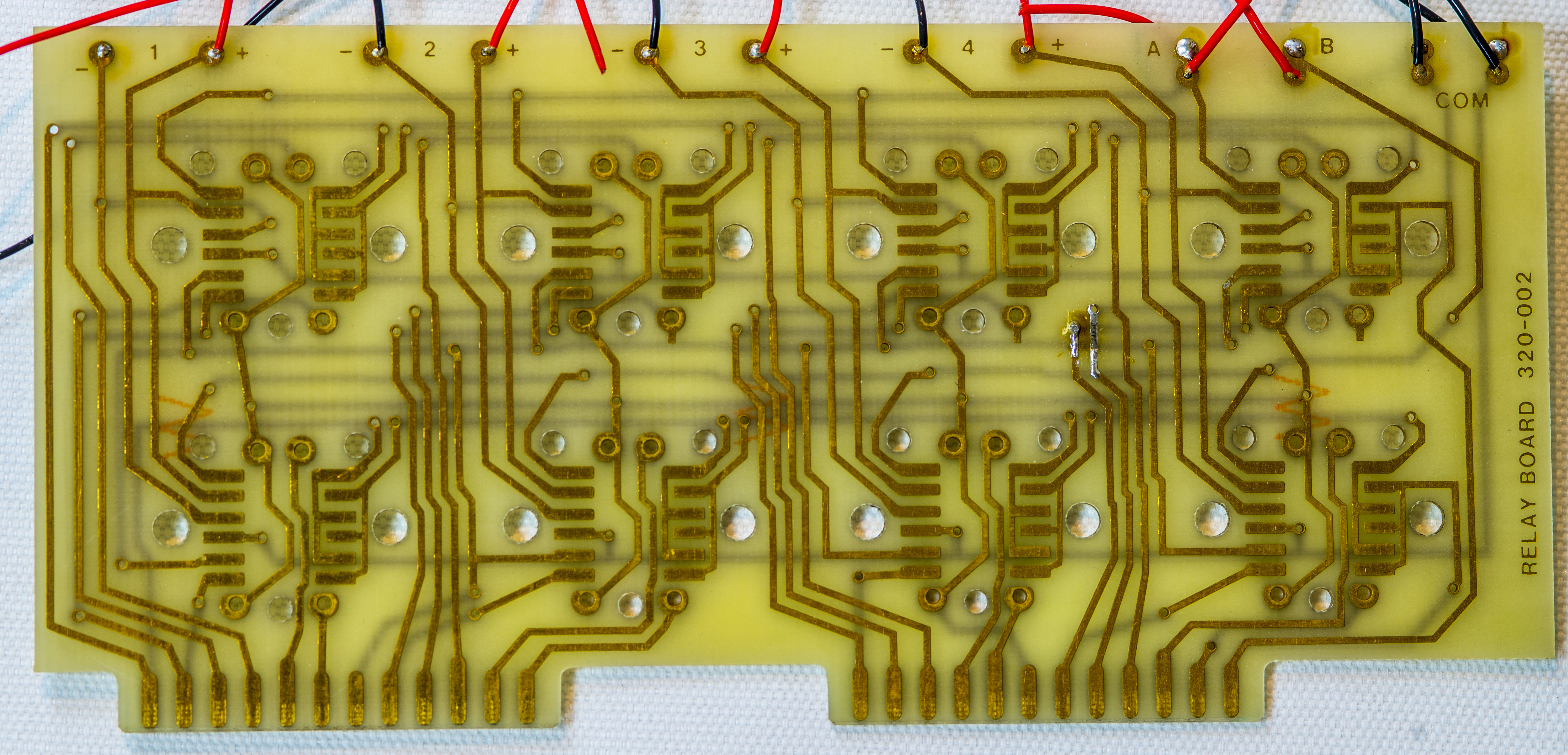
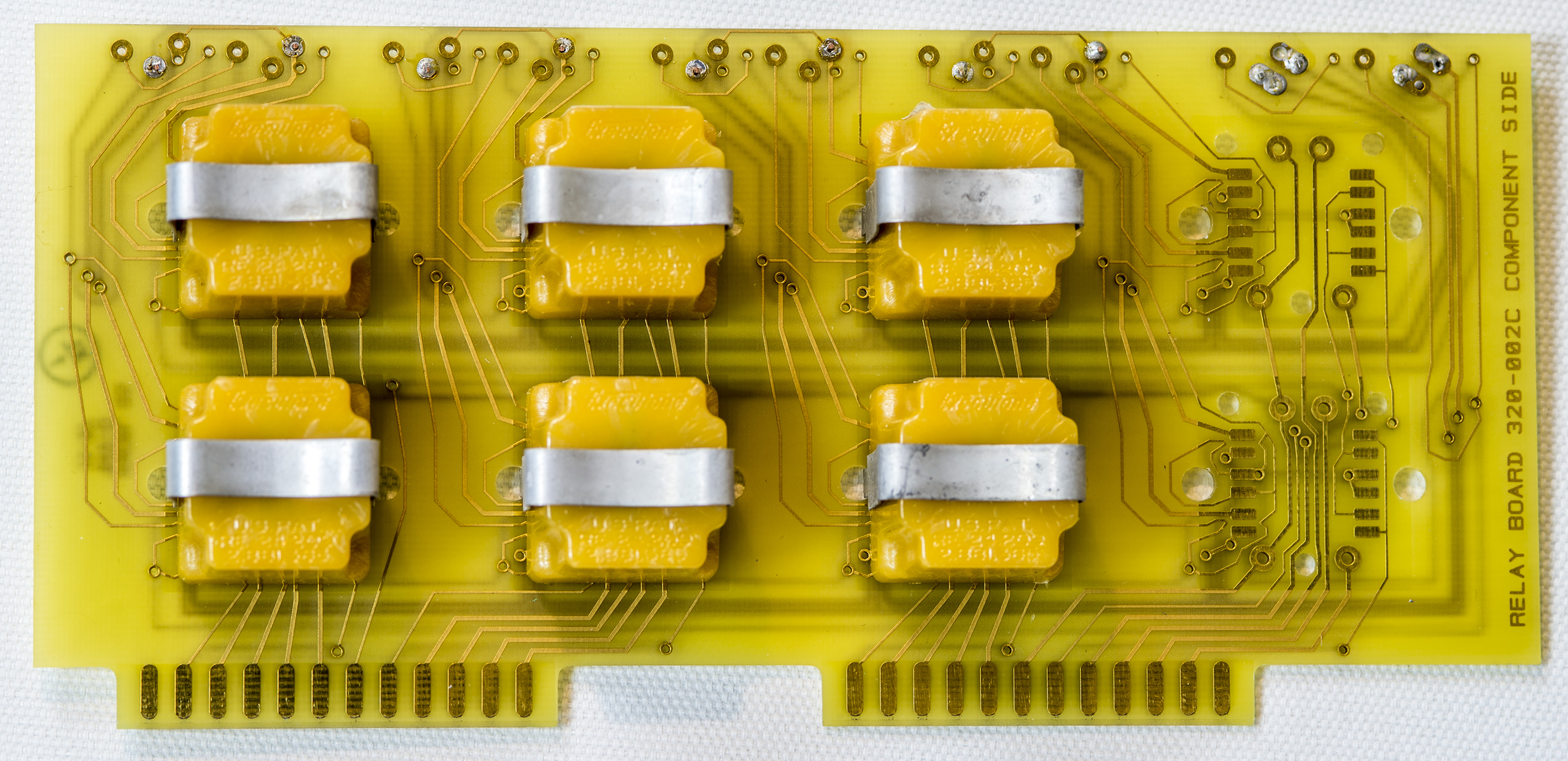
PCB photograph with eight latching relays, two per each contact pair for both A and B outputs:
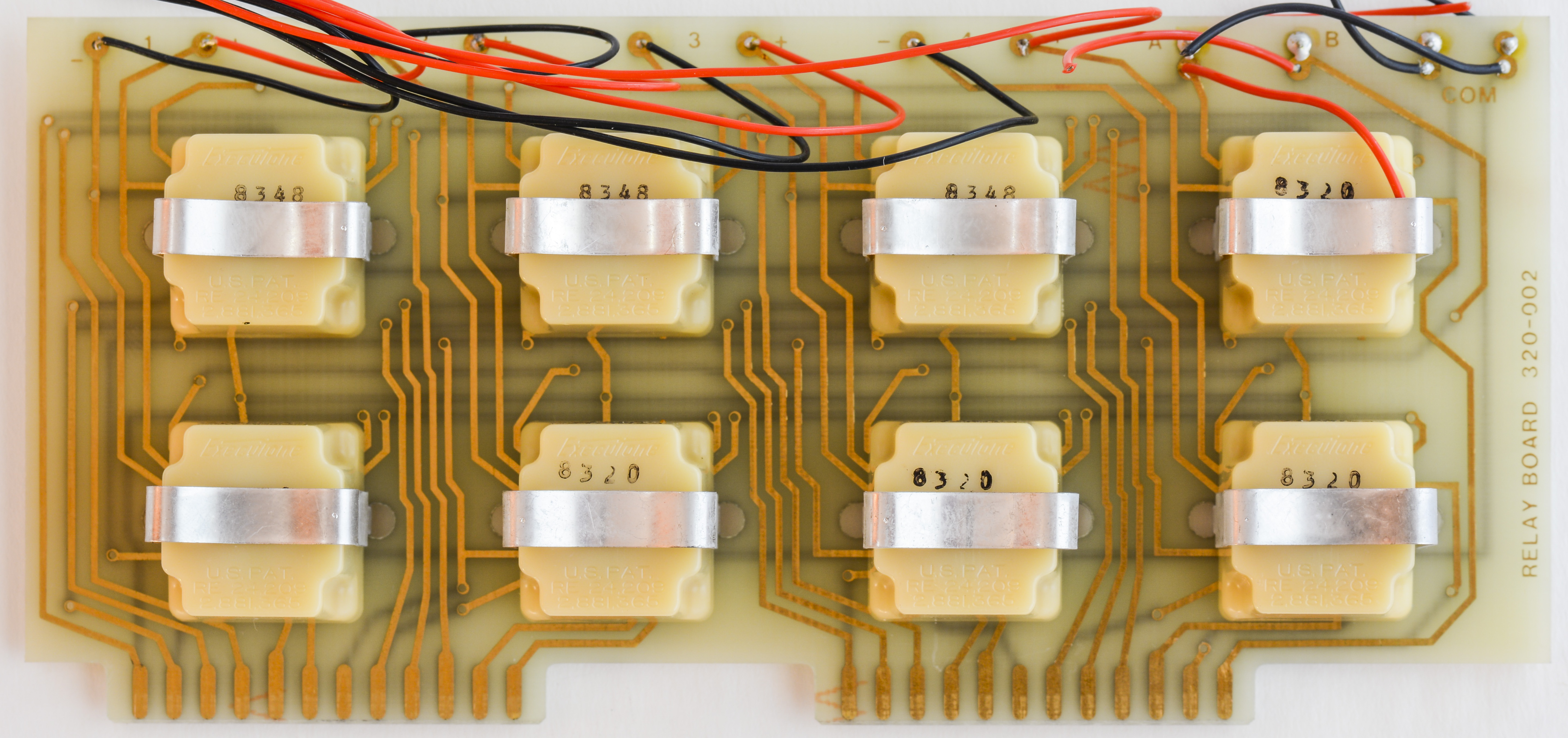

Images 36-37: Relay PCBA with all four channels
Schematics for this PCBA is available as well:
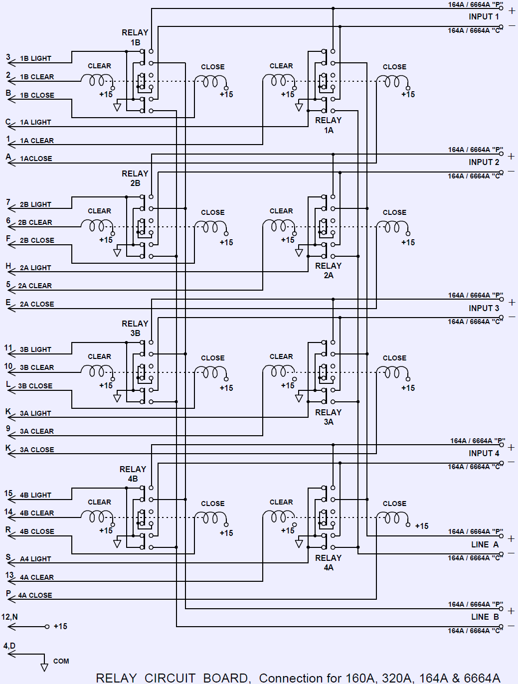
Special relay construction was used to achive stringent thermal EMF specifications. Both contacts and moving brush are gold plated to ensure long life and reliable connections over long term period.
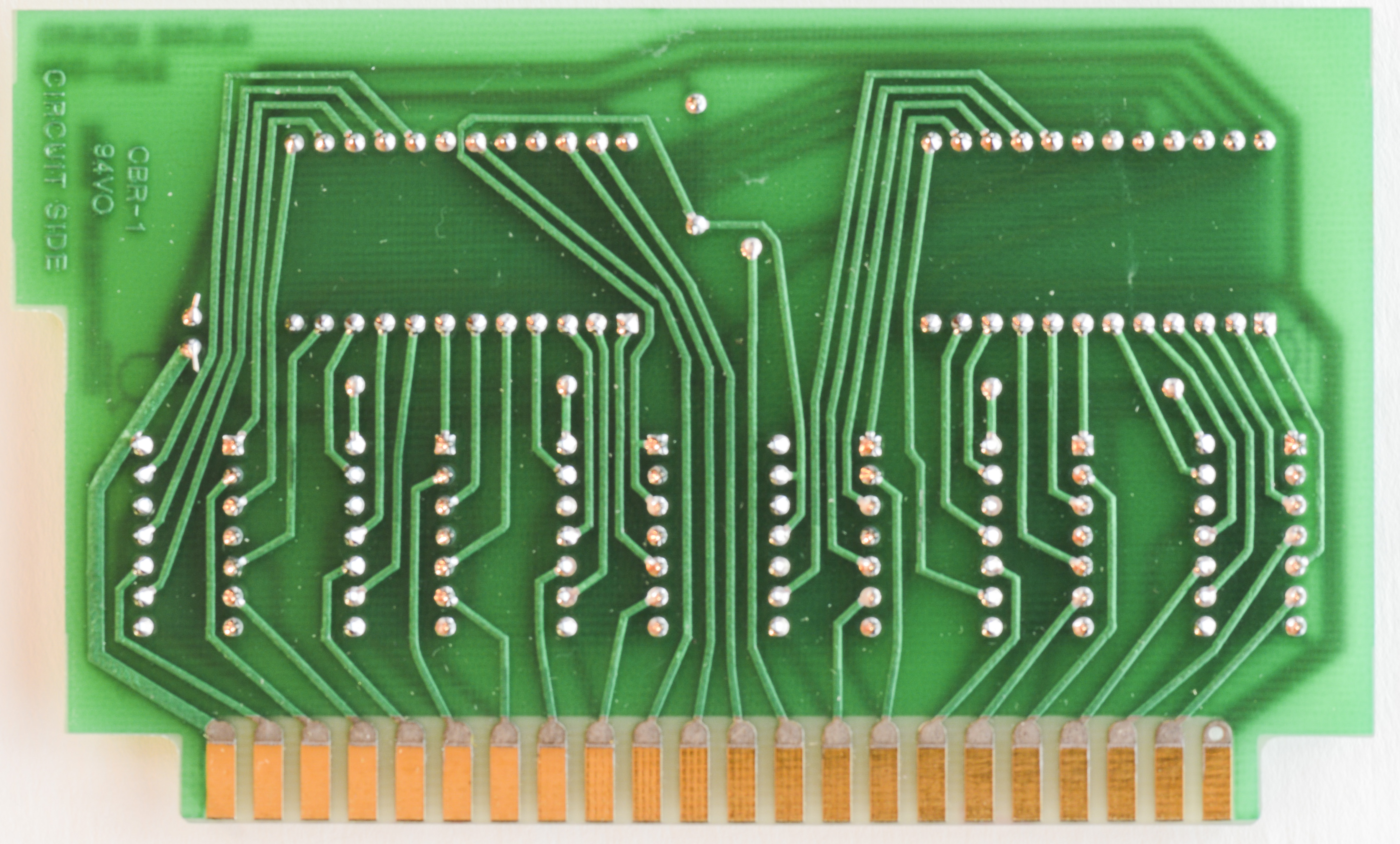
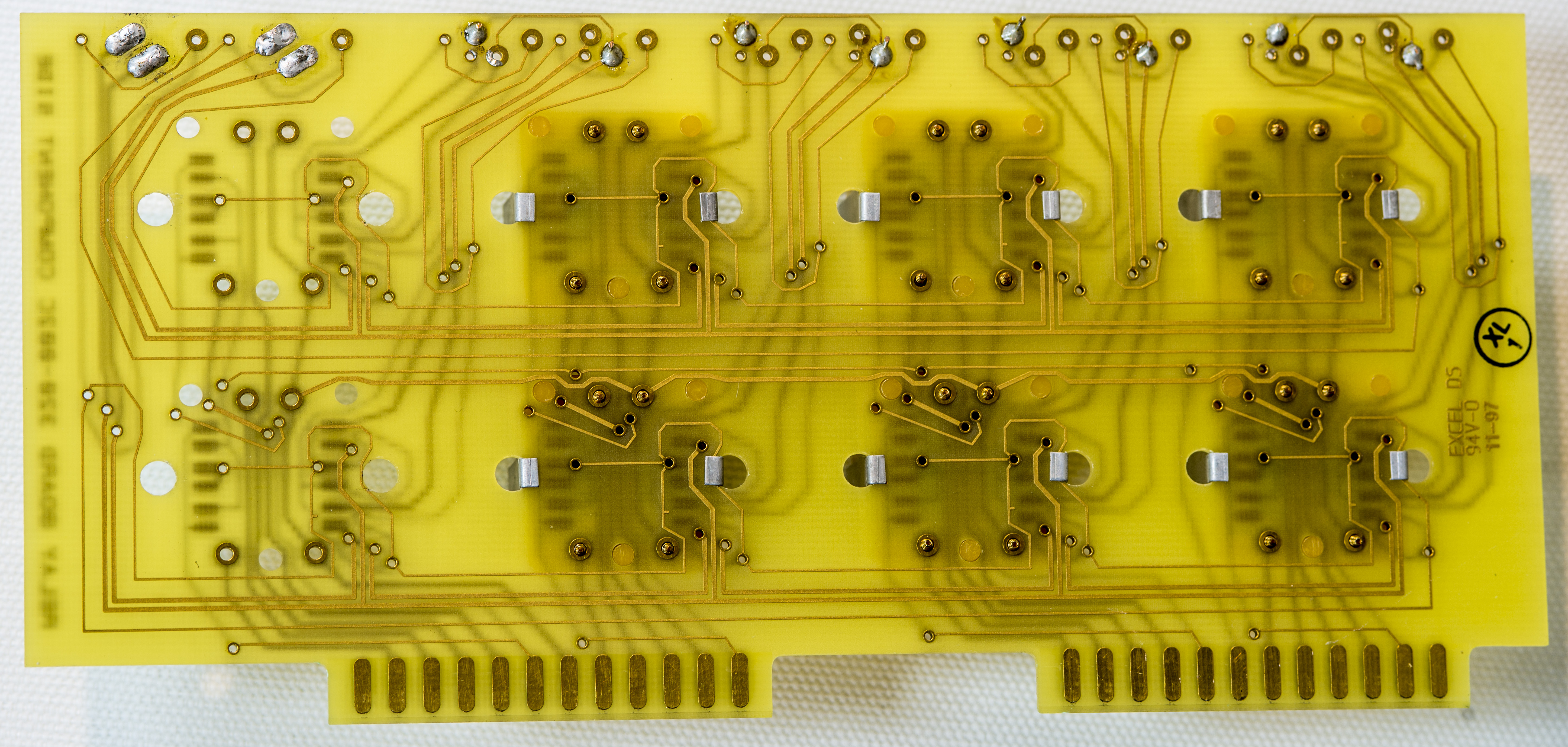
Guarded switch channel boards
There is also special Option 3 version of Data Proof scanner dedicated for resistance measurements. It is used modified layout of relay boards, PTFE guaded twinax cables and tested to provide much higher insulation resistance.
Below photos of such option boards with relays and also with relays removed to follow layout.
Actual relays used on both standard and low-leakage guarded boards are same.
Schematics of this board shows use of additional two contact pairs to route LO GUARD and HI GUARD nets to the output.
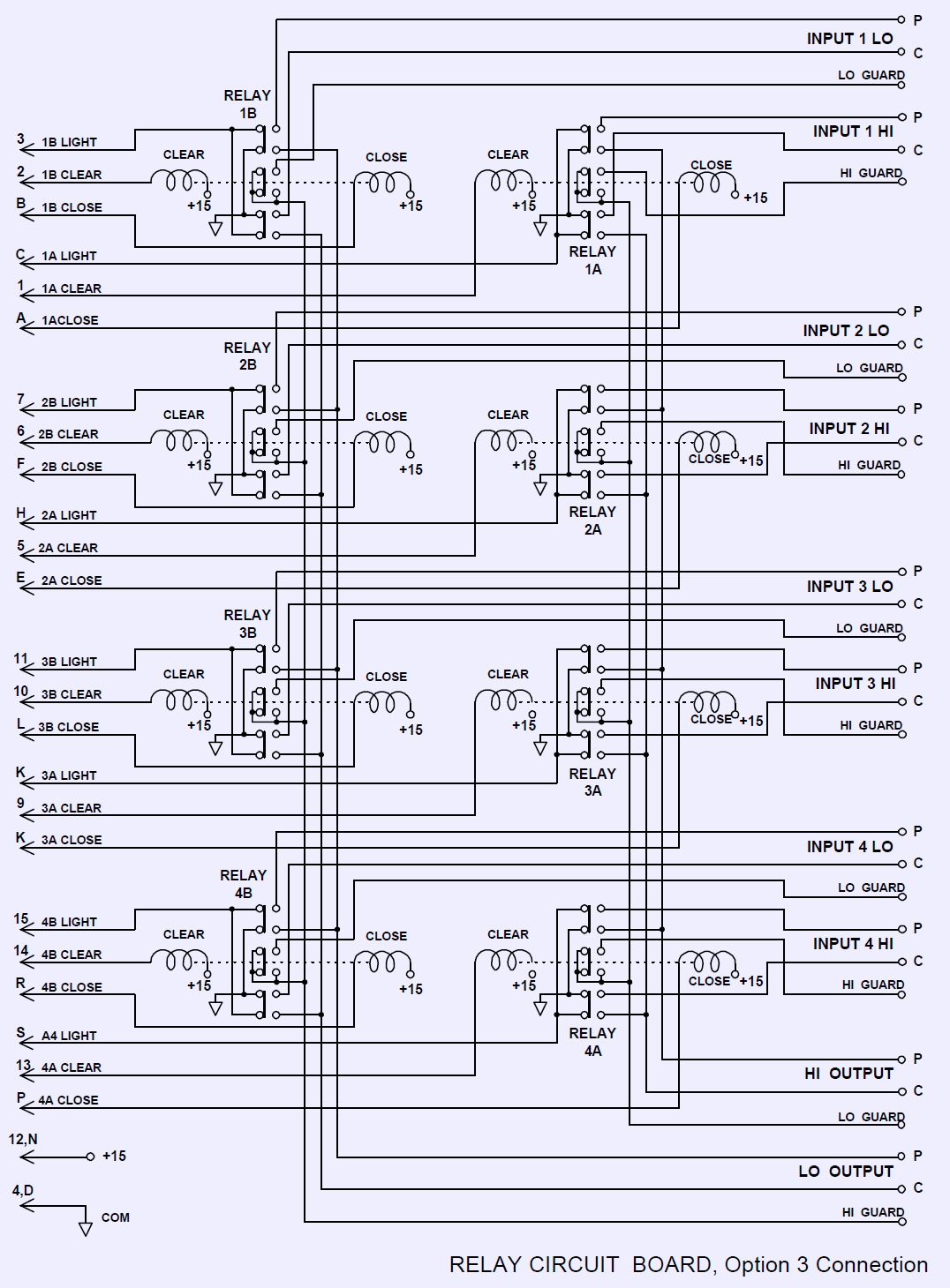
Remaining part of scanner is essentially identical to standard voltage scanner one.
This PCBA is NOT interchangeable with regular scanner (non-Option 3) because contacts and pinout map on edge connector is different to standard board. So scanner has to be wired to matching relay cards.
Service
The option 2 scanner is an older model that had dry rotted foam. It was all removed and new foam was procured to replace it. The interior floating chassis is surrounded by foam on all six sides.
One scanner was received with broken plastic pushbuttons. Data Proof was contacted for a quote on the needed buttons and they sent 10 new ones without charge even though the scanner is no longer manufactured. A big thumbs up to them for the kind service that is lacking in the high-tech industry.
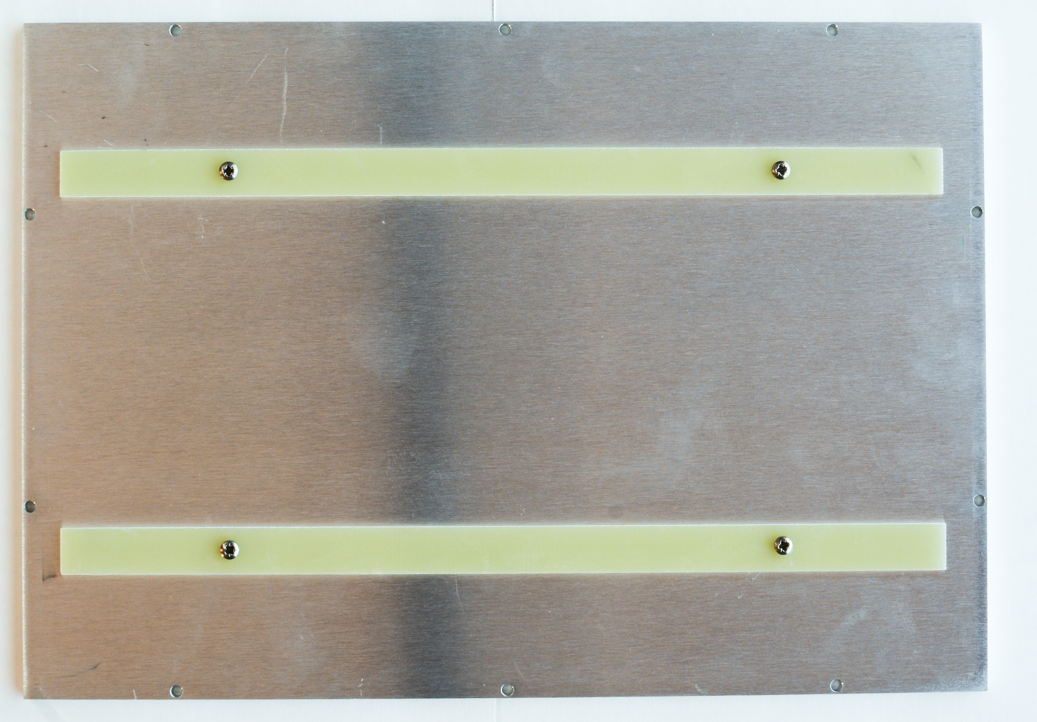
A lid was missing from the option 2 scanner and a new cover was cut at a local aluminum supply house. The cover is currently held in place with packing tape. It is not being used at the moment so no additional work was performed on it.
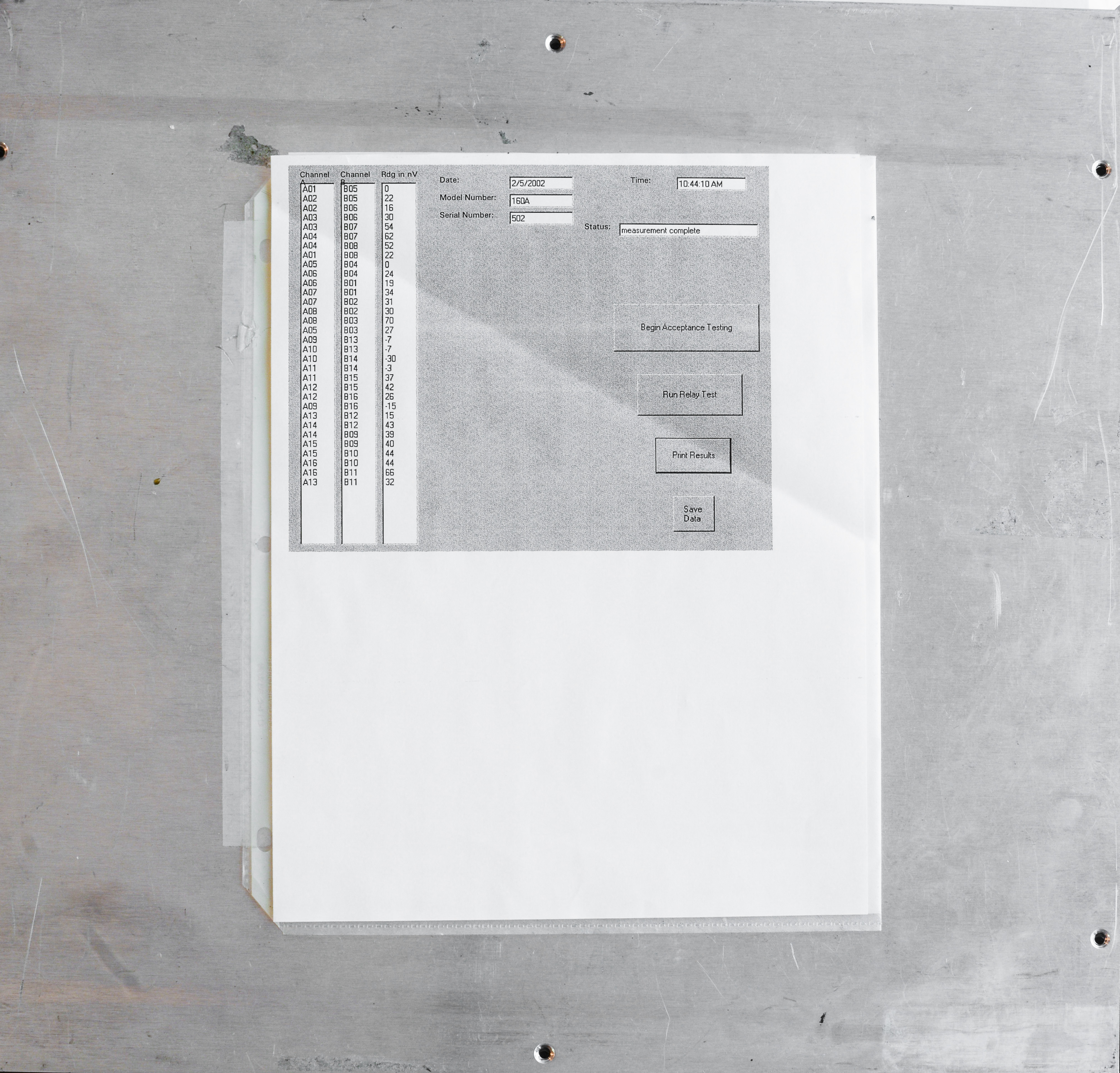
Test software for scanner
GPIB protocol
The commands are limited to enabling or disabling relays using a single letter and two digit number to represent all possible relays. For example, to close relay A1, a command of “A01” is sent over the bus . The B side is done the same way. To open all relays at once on the A side, the command “A00” is sent. The 0 is mandatory for all channels from 1 to 9.
Little helper Python class to interface scanner is presented below
class Timeout():
  """Timeout class using ALARM signal"""
  class Timeout(Exception): pass

  def __init__(self, sec):
    self.sec = sec

  def __enter__(self):
    signal.signal(signal.SIGALRM, self.raise_timeout)
    signal.alarm(self.sec)

  def __exit__(self, *args):
    signal.alarm(0) # disable alarm

  def raise_timeout(self, *args):
    raise Timeout.Timeout()

class scanner():
    temp = 23
    data = ""
    status_flag = 1
    temp_status_flag = 1

    def __init__(self,gpib,reflevel,name):
        self.gpib = gpib
        print "\033[1;4H \033[0;33mGPIB[\033[1m%2d\033[0;31m] : DP 160\033[0;39m" % self.gpib
        if cfg.get('teckit', 'interface', 1) == 'gpib':
            self.inst = Gpib.Gpib(0, self.gpib, timeout = 180) # GPIB link
        elif cfg.get('teckit', 'interface', 1) == 'vxi':
            self.inst = vxi11.Instrument(cfg.get('teckit', 'vxib_ip', 1), "gpib0,%d" % self.gpib) # VXI link
            self.inst.timeout = 180
        elif cfg.get('teckit', 'interface', 1) == 'visa':
            self.inst = rm.open_resource('GPIB::%d::INSTR' % self.gpib)
            self.inst.timeout = 300000 # timeout delay in ms

        self.reflevel = reflevel
        self.name = name

    def set_channel(self, port, number):
        self.inst.write("%c%02d\n" % (port, number))
        time.sleep(0.25)            # Necessary delay to allow DP scanner to actuate relay reliably
To use it initialize the class device scanner and then select desired channel following simple procedure scanner.set_channel(A,xx) where XX is a channel digit. For example setting CH5 would mean sending scanner.set_channel(A,05).
Some benchmarks of DataProof scanners
First test is to measure thermal EMF offsets with sensitive nanovoltmeter and bare copper shorts on all all relay channels (HI to LO shorted).
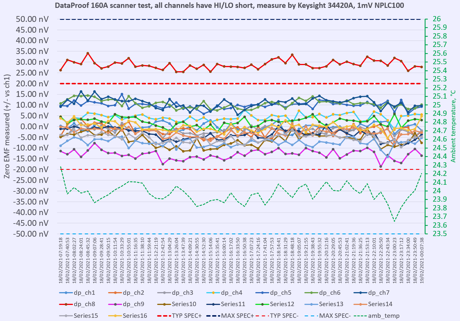
Pretty happy with results. Relay board that has CH5,CH6,CH7,CH8 relays show some higher offset, with CH8 being the worst out of typical spec. This was resolved after replacing whole board with spare.
But even before swap, bad CH8 was within maximum vendor spec, just a tiny bit under 35nV. 35nV error in case of 10V DC voltage measurement error would translate into 0.0035 ppm, which can be ignored for all practical reasons and purposes.
Also it was interesting to verify warm-up time after scanner sat for some time cold during relay board replacements.
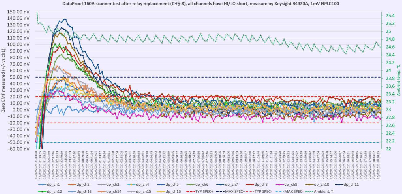
It took about 8 hours to fully settle under typical +/-20nV limit. Yet another indicator why it is best to keep equipment always powered on, even if not used in actual measurements when it comes to high-end metrology and high performance requirements.
Actual scanner used in measurements is 160A with 4 standard cards:
Practical experiment was setup to measure 12 different 10V DC voltage references available in the lab.
xDevs.com’s custom 792× 10V LTZ1000ACH-based reference was used as calibrated standard with voltage 9.9999698 VDC ±0.4ppm and all voltages of other standard were calculated from this value.
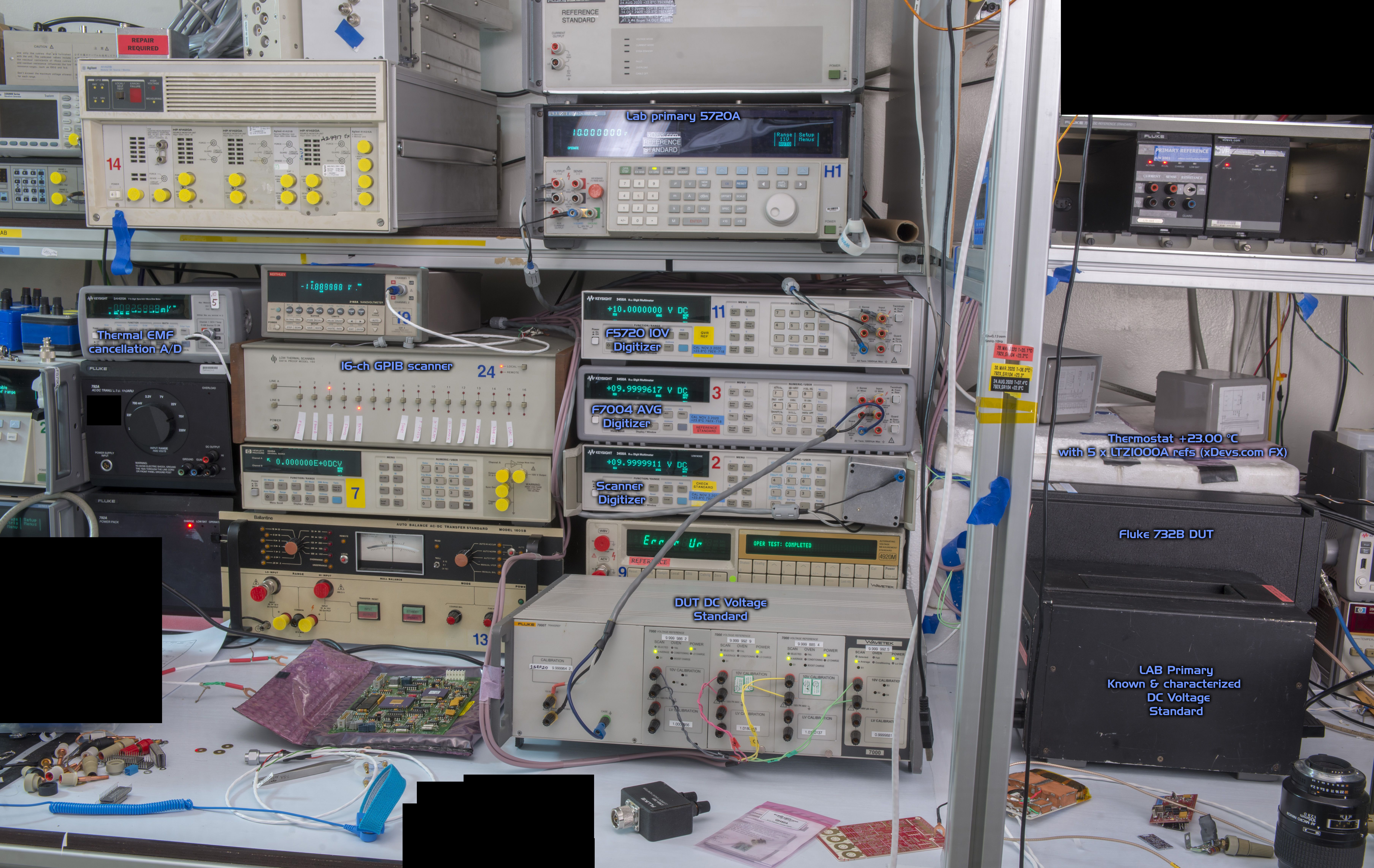
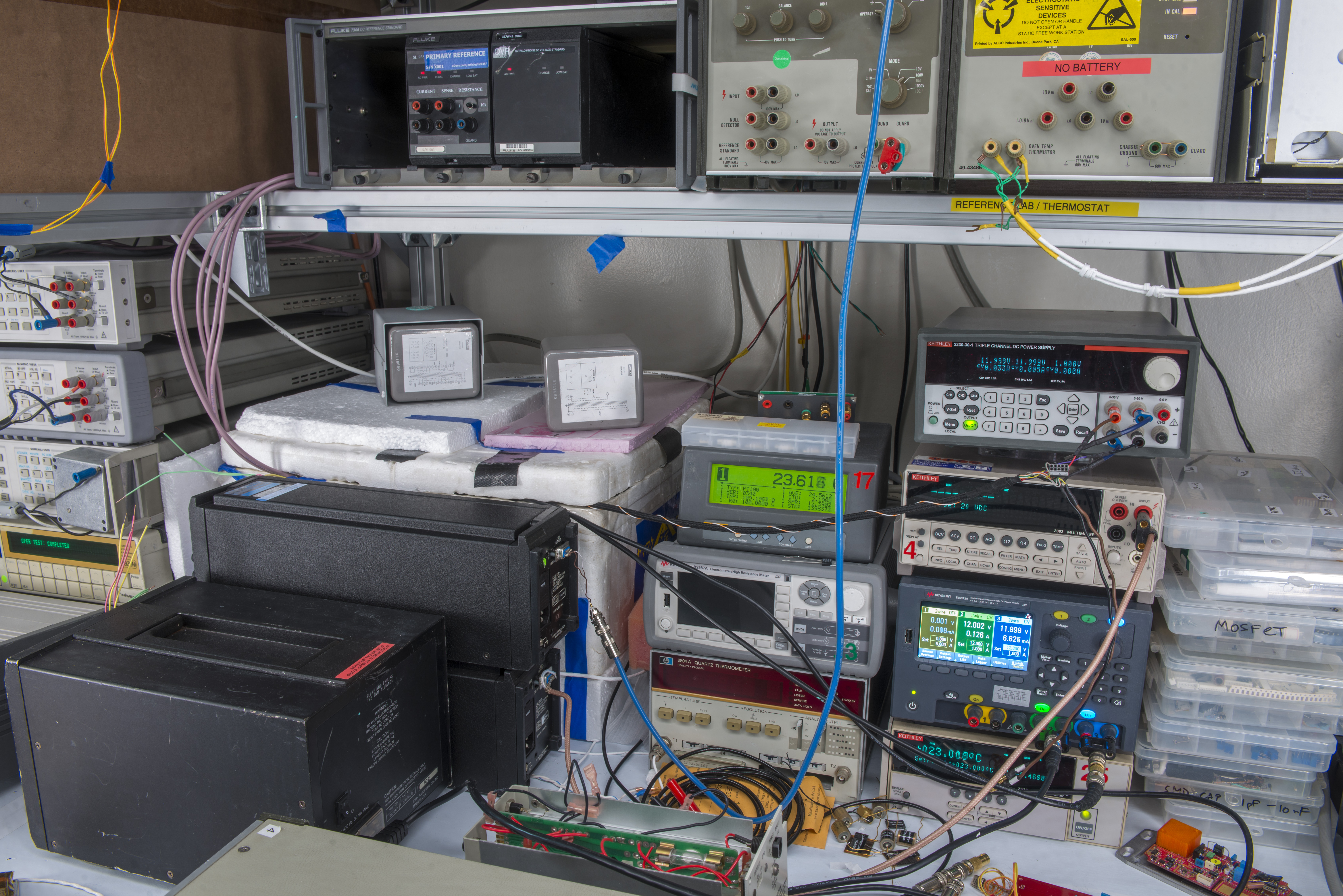
Rest of references and power supply section:
Stability over 2 days show average peak to peak deviation about ±0.2ppm. There was no special shielding or isolation methods used during this measurement experiment.
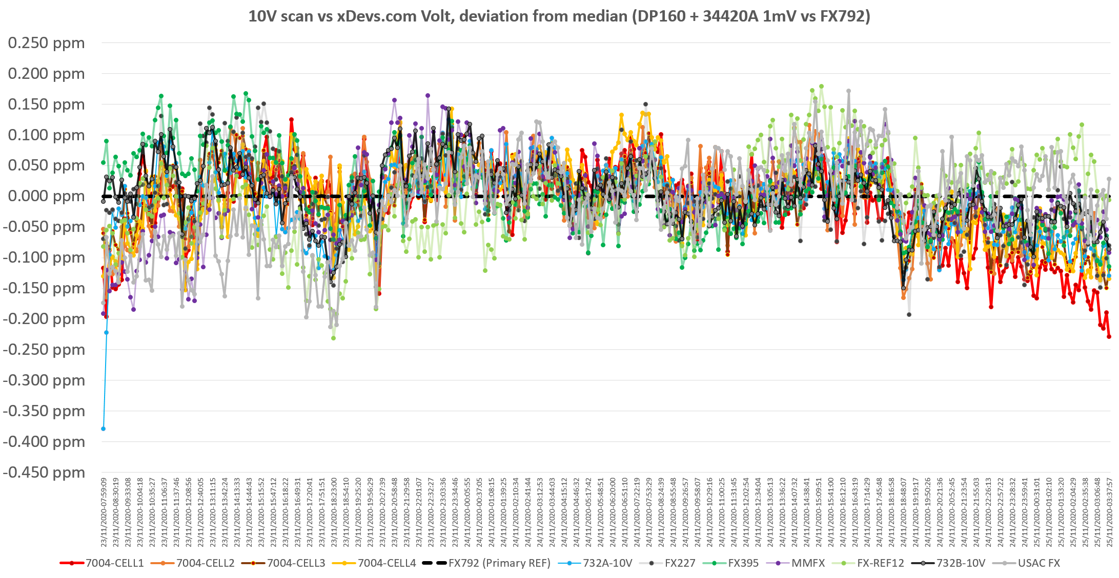
Actual RAW data file in Excel format is also available:
Excel-file with RAW samples from voltage bank scan
Conclusion
Both of these Data Proof switch units are planned for use in multiple resistor standards evaluation and performance testing, as well as some voltage reference comparisons and experiments. Stay tuned and post any comments or feedback.
Modified: Jan. 23, 2024, 5:10 p.m.