Contents
Intro
We had no luck to get infamous 3458A affordable enough (Update in 2015, I got broken 3458A for repair project now), so went to very familiar route, with Keithley Instruments. Like some say, it can’t be enough DMMs, no matter how many one have. We already have dozen of Model 2001 meters, which we abuse and tear down to pieces on daily basis, covering journey in this thread at EEVBlog and our own Redmine tracker.
Welcome Model 2002 in it’s beauty, probably smallest 8.5 digit meter on market. It’s still current model, and officially avalable thru official manufacturer website, just like 20’year old 3458A :). To my surprise this one don’t require any fixing/repairing or other mess, very unlike my 20 year old 2001’s :D
Everybody who saw Keithley 200x/7001/24xx/26xx ones, will know how 2002 look like, so I’ll post overall view and menu/settings tricks later.
Disclaimer
Redistribution and use of this article or any images or files referenced in it, in source and binary forms, with or without modification, are permitted provided that the following conditions are met:
- Redistribution of article must retain the above copyright notice, this list of conditions, link to this page (/review/kei2002/) and the following disclaimer.
- Redistribution of files in binary form must reproduce the above copyright notice, this list of conditions, link to this page (/review/kei2002/), and the following disclaimer in the documentation and/or other materials provided with the distribution, for example Readme file.
All information posted here is hosted just for education purposes and provided AS IS. In no event shall the author, xDevs.com site, or any other 3rd party, including Keithley or Tektronix be liable for any special, direct, indirect, or consequential damages or any damages whatsoever resulting from loss of use, data or profits, whether in an action of contract, negligence or other tortuous action, arising out of or in connection with the use or performance of information published here.
If you willing to contribute or add your experience regarding test instruments repairs or provide extra information, you can do so following these simple instructions
Manuals
Here are available manuals from KI so far.
Model 2002 Calibration certificate example
Model 2002 Repair manual, Rev B
Model 2002 User’s Manual, Rev E, Feb 2009
Model 2002 Getting Started Manual, Rev A, May 1994
Model 2002 Calibration Manual, Rev D, May 2004
Model 2002 Multimeter Specifications, Rev I, Nov 2009
As with all recent Keithley gear, schematics or detailed construction information is not available. Best we have is repair manual troubleshooting hints, self-test diagnostics description and part list (which is helpful too).
Teardown
For now we start with real stuff, teardown and I actually shoot video-review.
And resources + hi-resolution photos of things inside below:
All photos clickable/zoomable :D
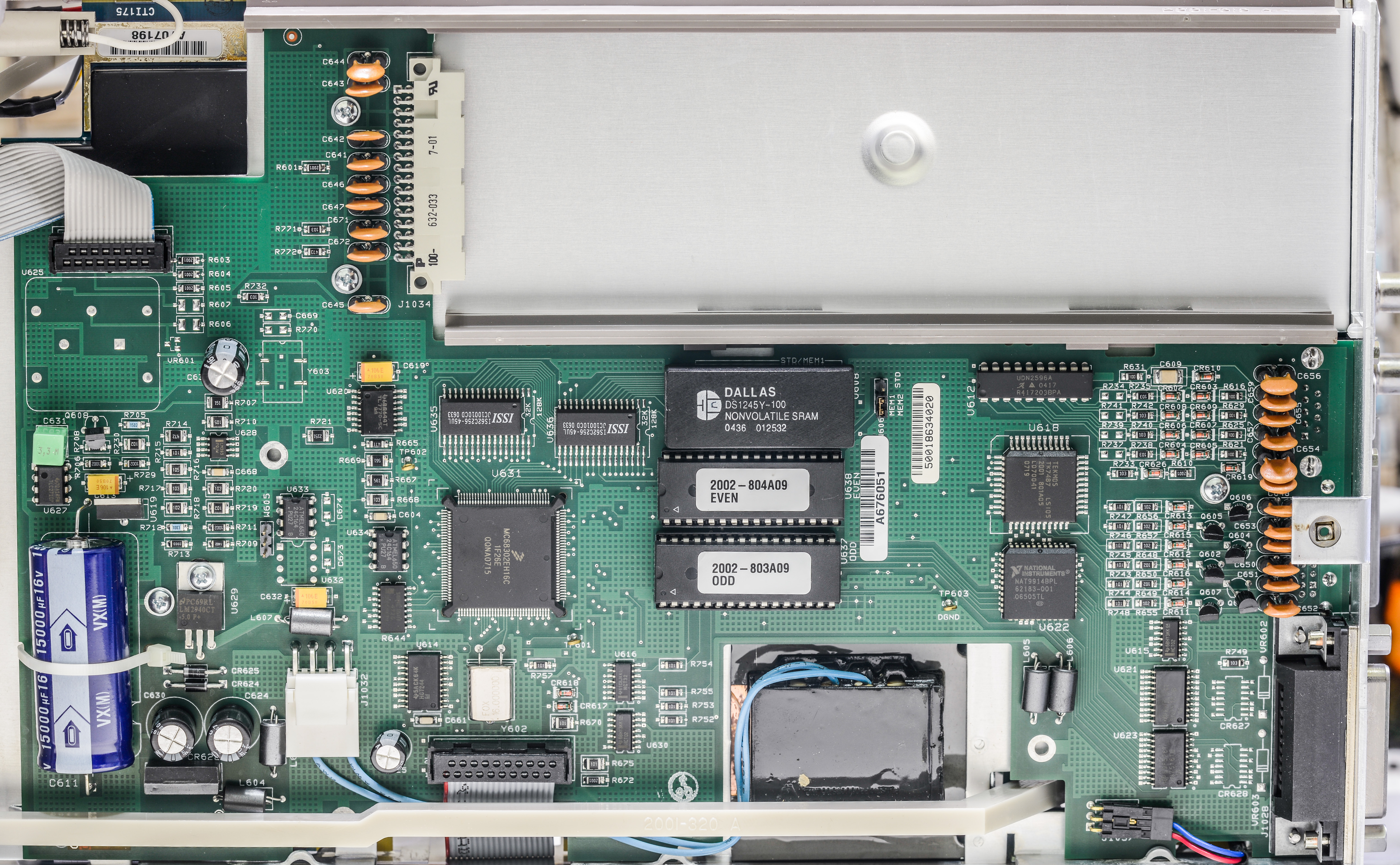
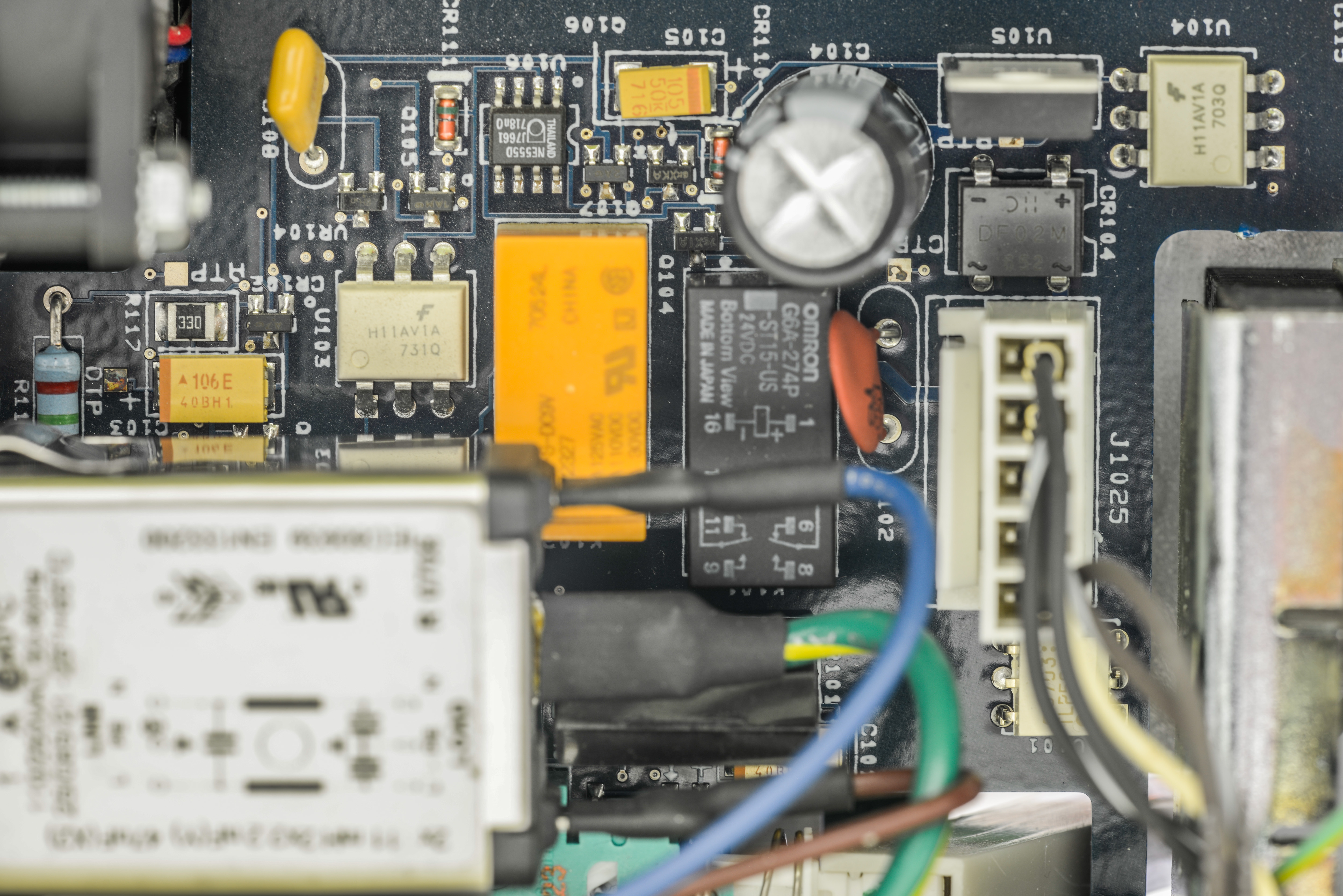
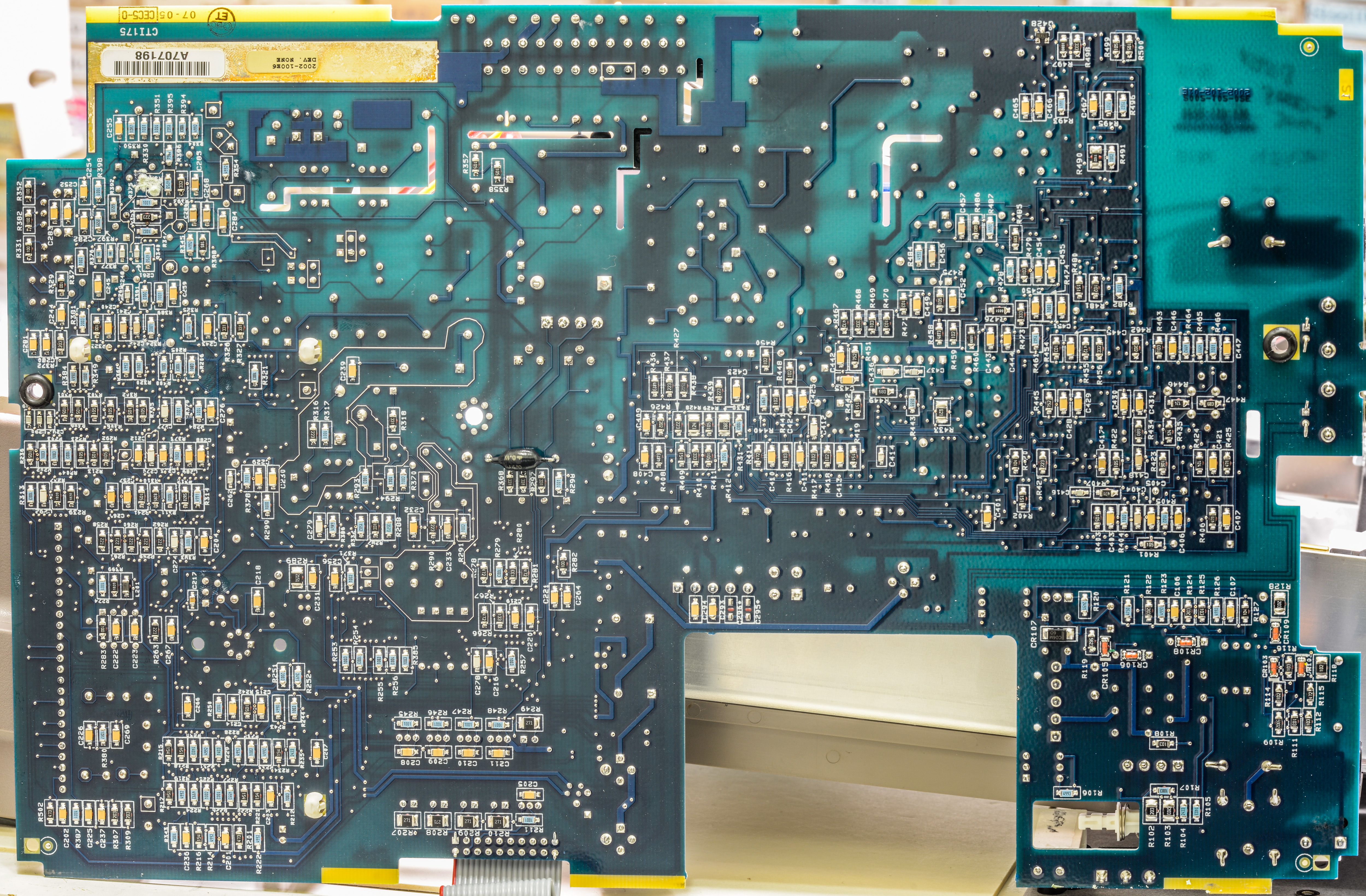
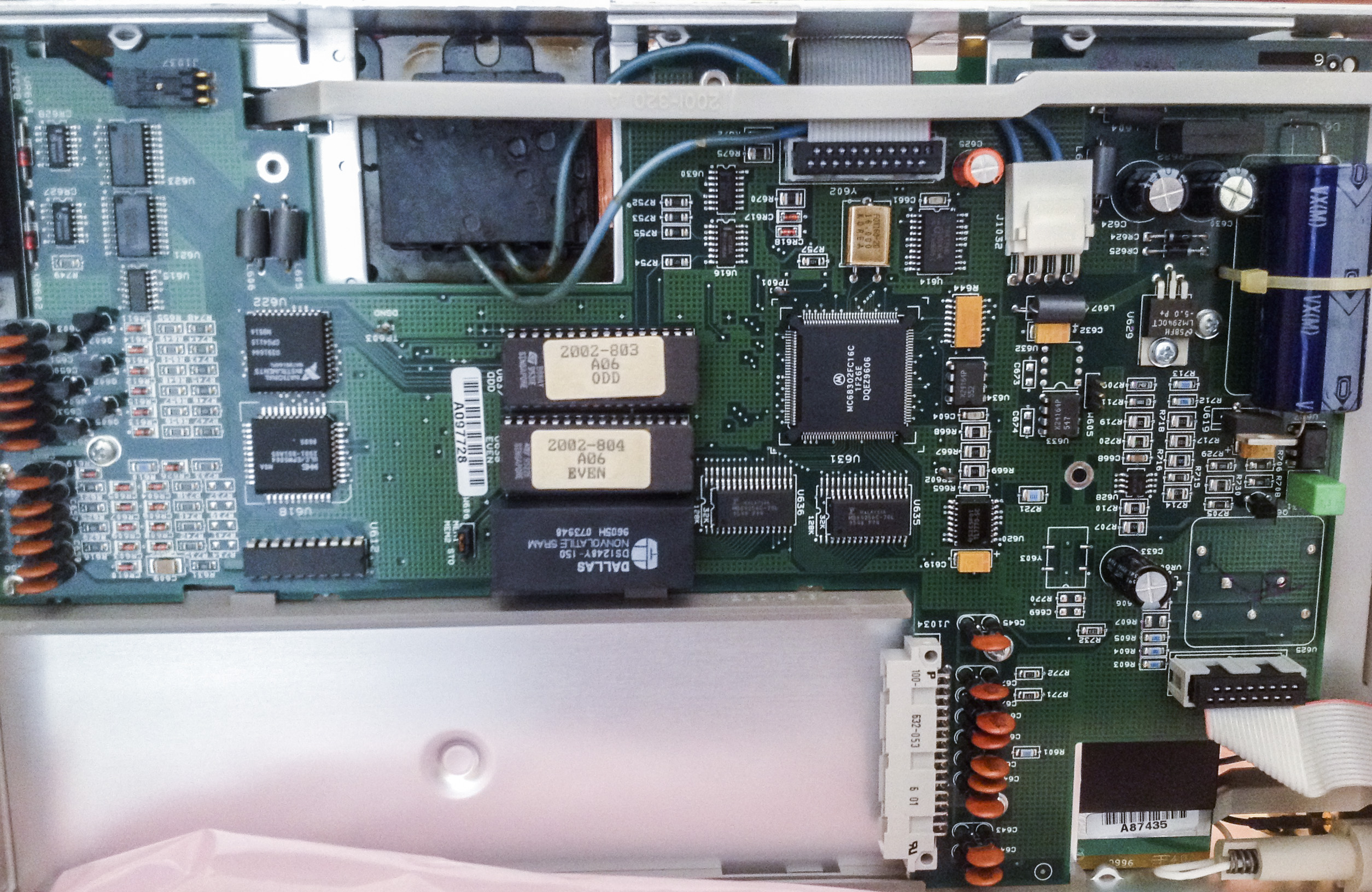
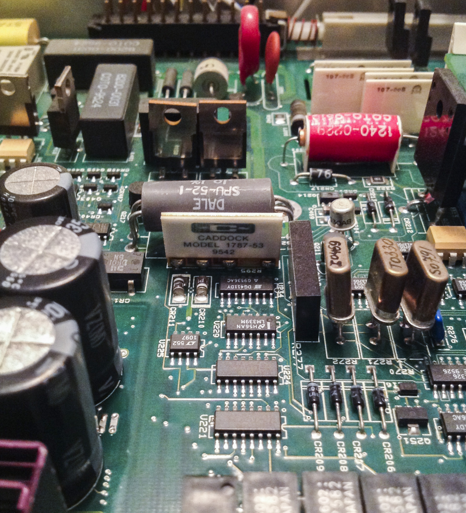
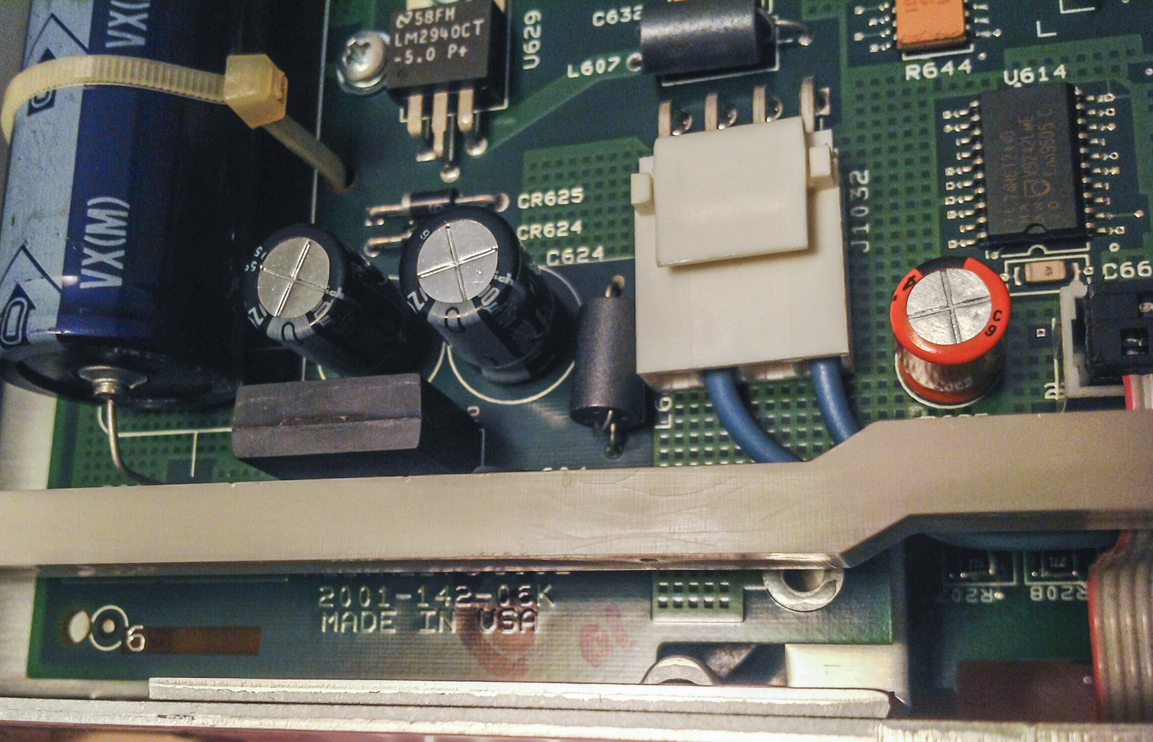
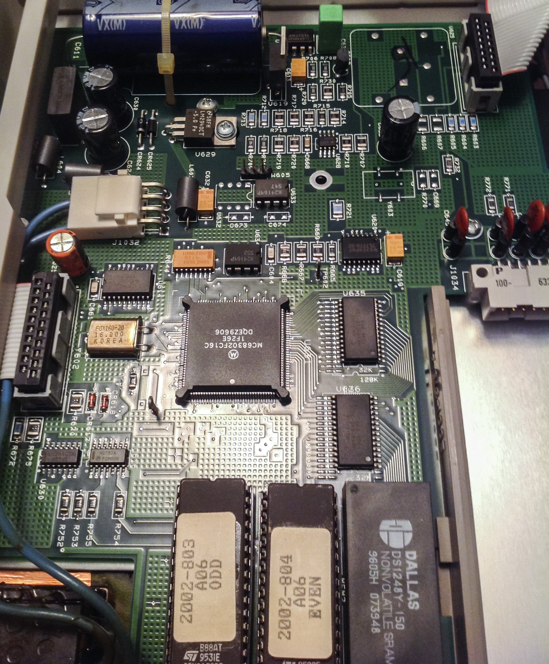
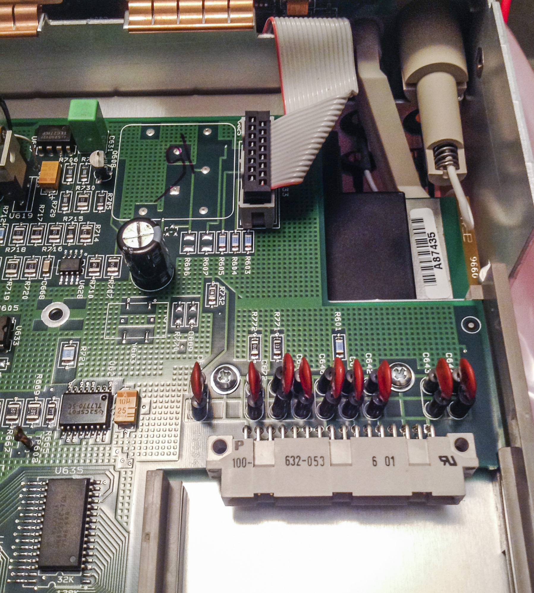
Digital board. It’s 2001-142, Revision K. Very same board as in my second Keithley 2001.
Differences on BOM level:
- High-voltage DC-DC module (block near front panel connector) (+5V to filament VAC and +60VDC for VFD) moved from digital board to front panel.
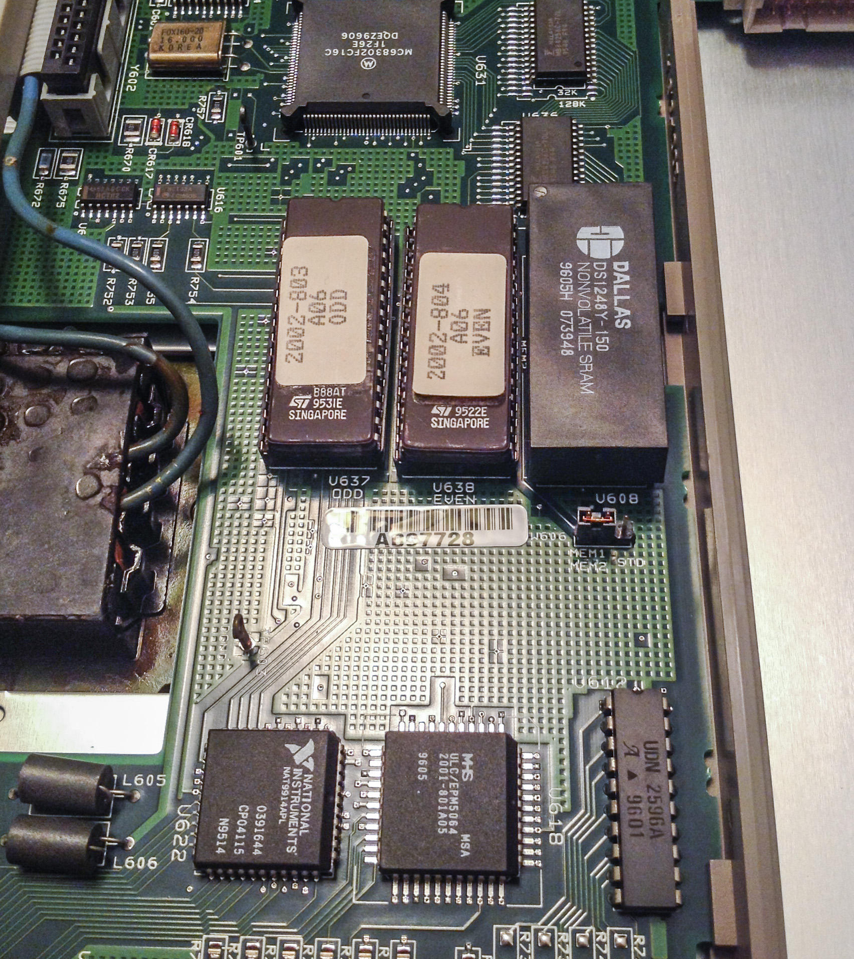
- STD option used DALLAS DS1243 (NVRAM with Phantom RTC clock), MEM2 likely to use bigger version, such as DS1248 or DS1251
- Extra I2C 24C16 EEPROM on position U633 for calibration constants/data?
- Firmware for Model 2002
- Missing protection diodes on GPIB port interface (while www.38hot.net BBS 2002 had them on)
- Small ALTERA MAX5064 CPLD for trigger-link replaced by TEKMOS 2001-801-A05 ASIC
- 4MHz clock moved to front panel too.
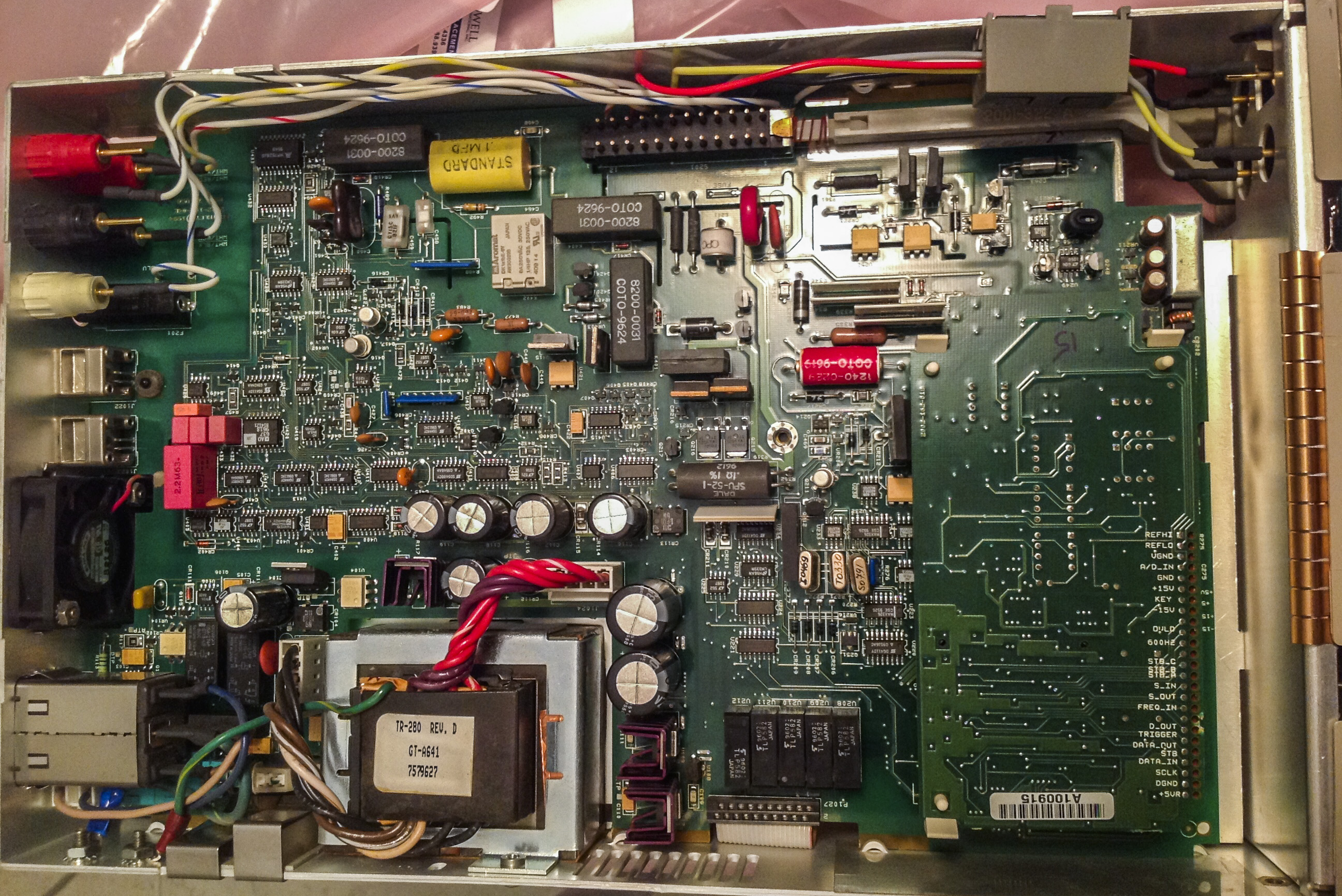
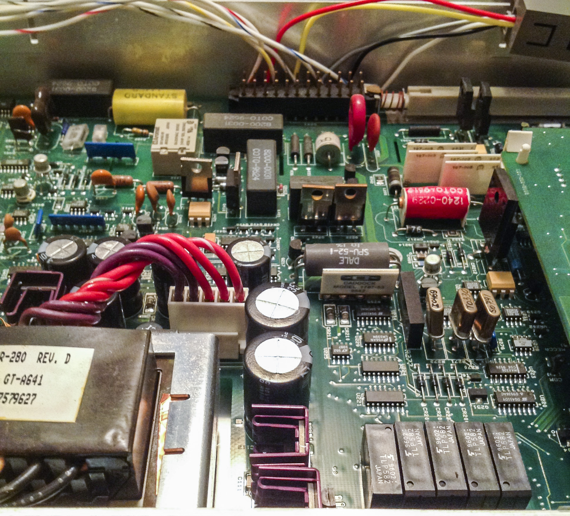
Analog board is different story…

In general construction and functional units are same, but in critical areas using more precise components with tigther tolerances/less tempco. Voltage reference changed from aged/selected LM199/399 to LTZ1000ACH.
There are now two switching capacitor building blocks (Linear LTC1043CSW) paired with KEMET PC or PP film capacitors. Current source for resistance is using Vishay foil’s. Switching between ranges now using MAX326’s. Ohm measurement is almost same, 0.1ohm 1% kelvin resistor (but better tempco, +-10ppm by label on it) + 0.91ohm and Caddock 1737-53 network (same as 2001).
Same bootstrap circuitry as 2001’s (four big caps near transformer) with avalance diodes between them, same True-RMS AD637JR.
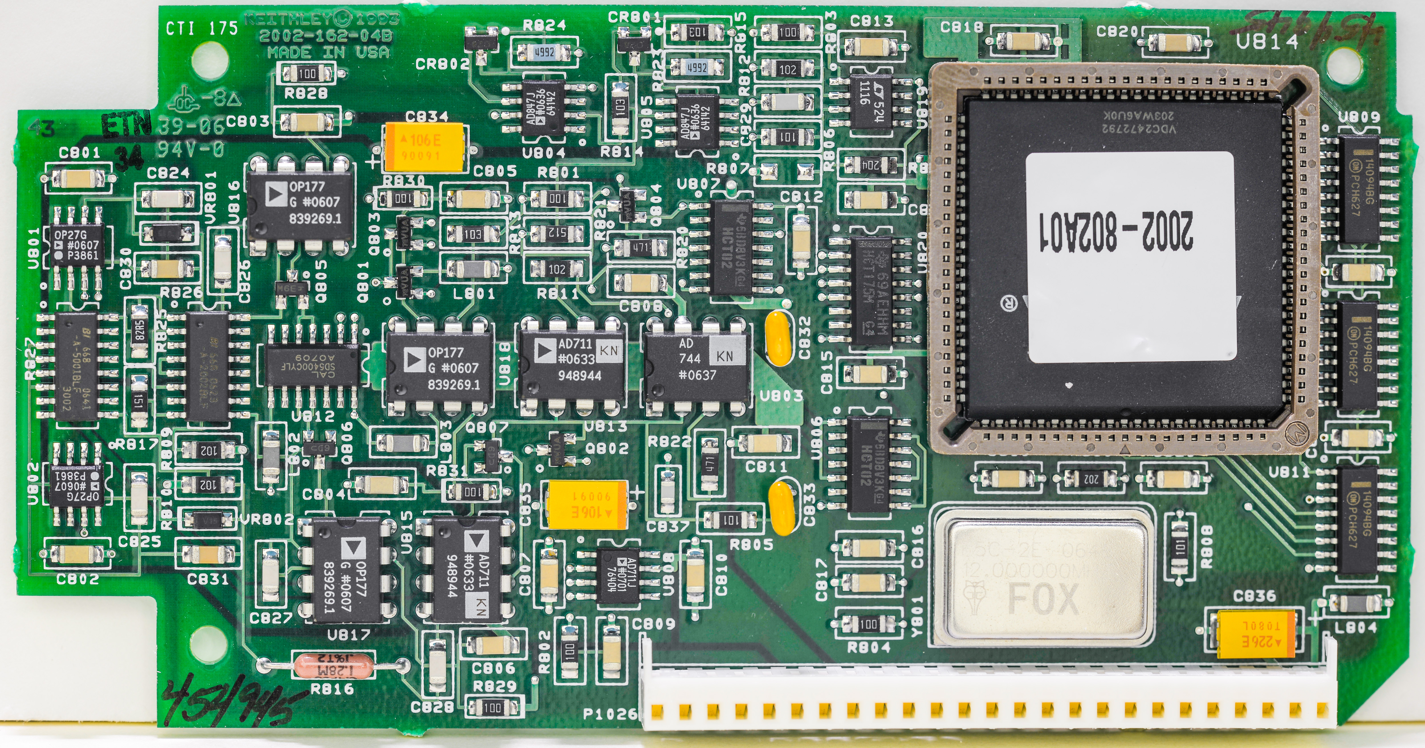
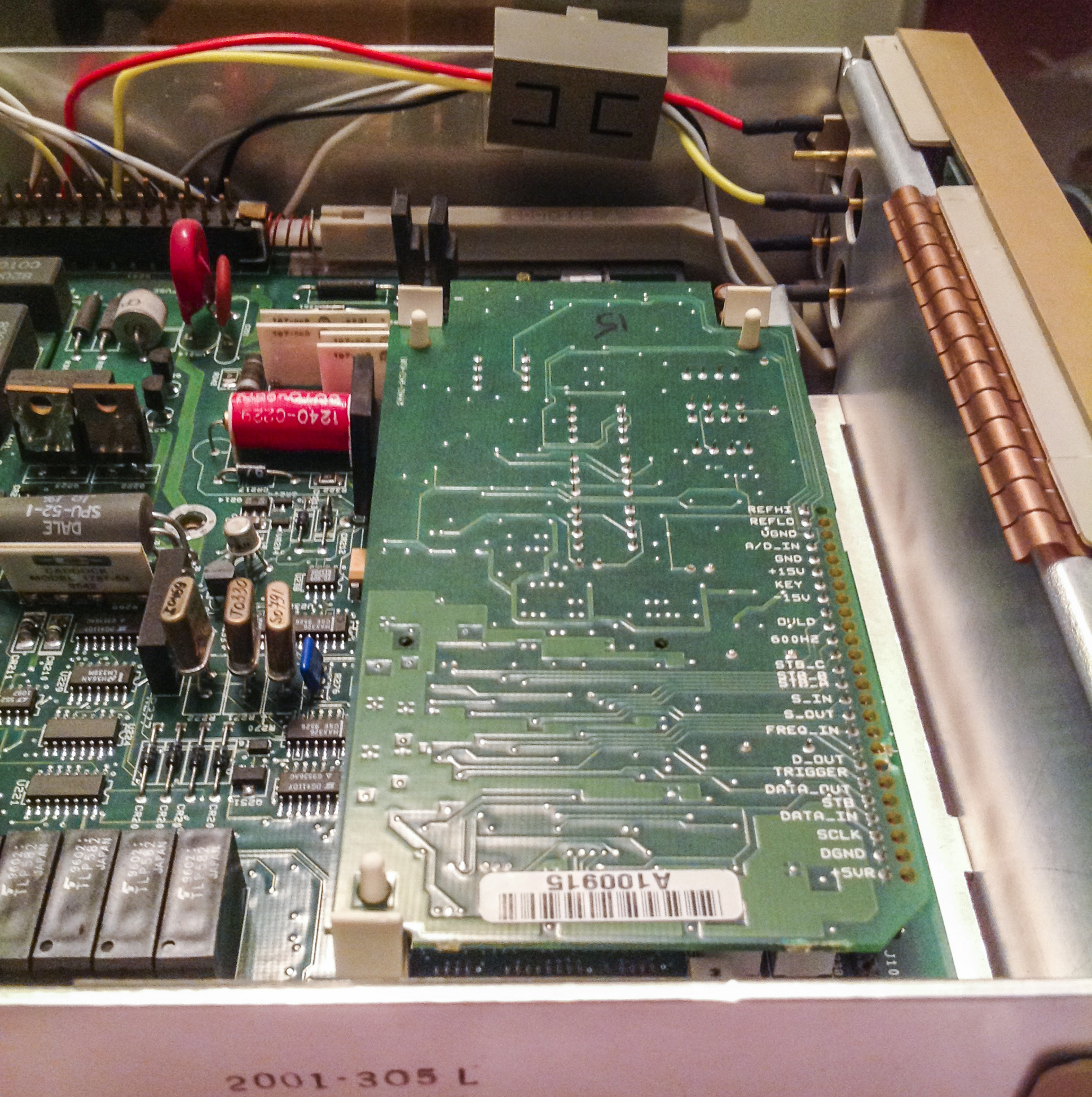
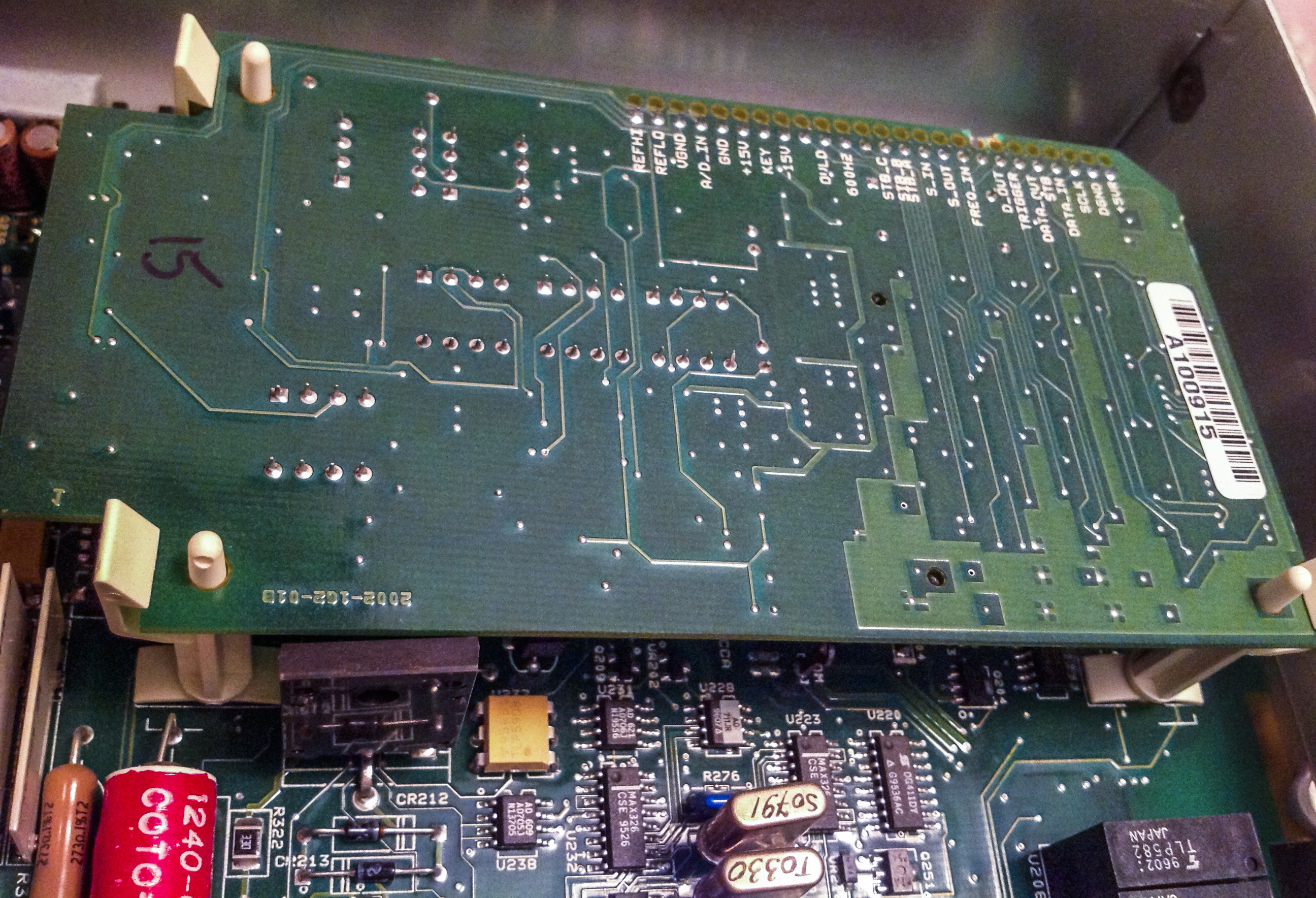
2002-162 4-layer PCB with ADC module now mostly completely SMT, designed in 1993 (yes, 21 years ago!).
It’s revision B.
Featuring ALTERA EPM7160 in PLCC84 package, configured to 2002-802-A01 RTL, and clocked from 12MHz FOX XO.As reminder, Model 2001 was using 7.68MHz with EPM7128 in PLCC64 :)
Some resistors now are in SO-16 networks (R827 and R825 on left side) Also I could not spot integrating capacitor, it’s probably one of NP0 SMD caps. Model 2001 ADC was using bulky film thru-hole cap rated to 400V.
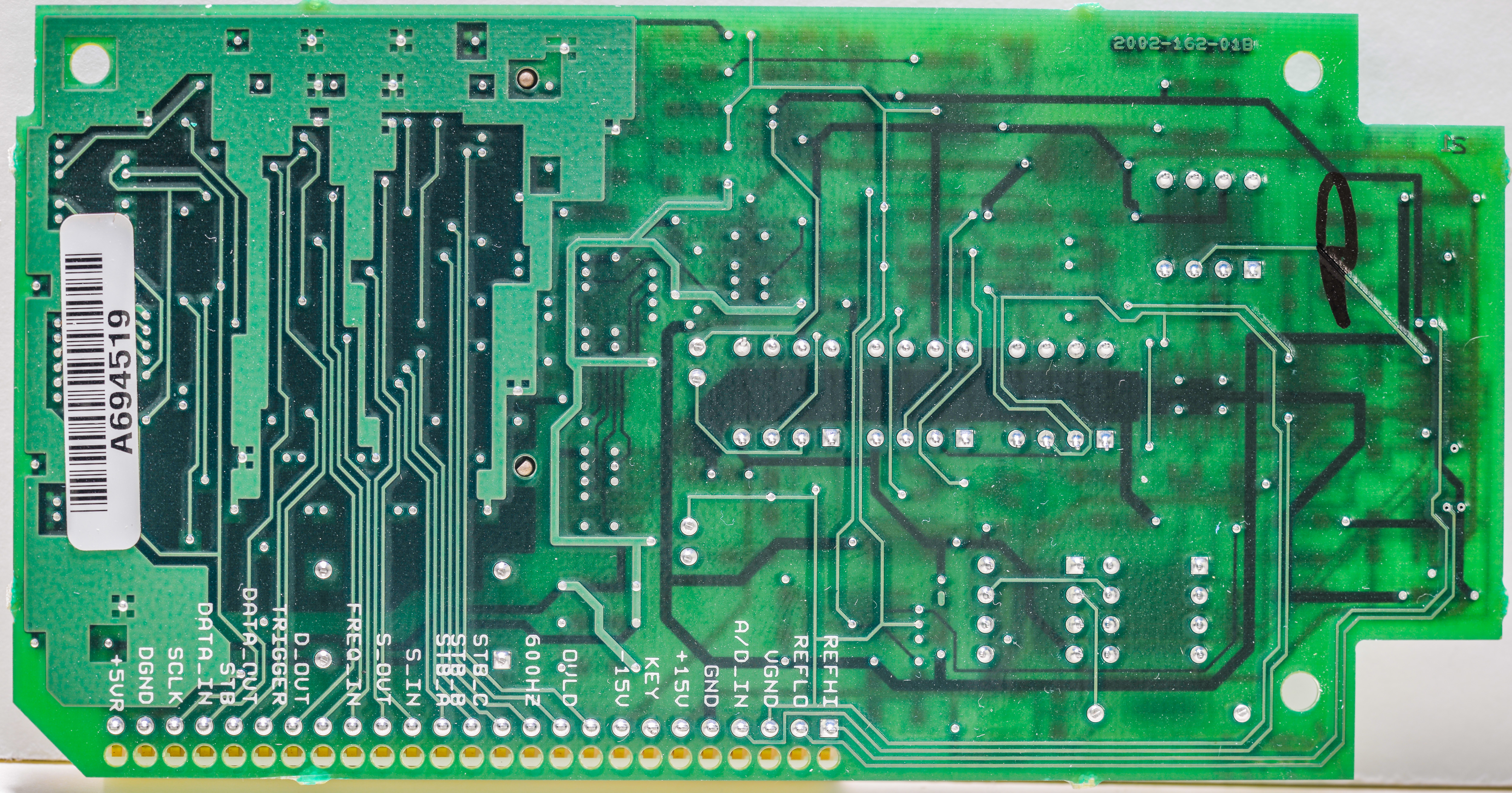
No components on back side, only nicely labelled interfacing connector. Reference voltage supplied differentially, REFLO and REFHI? with measured,it’s 7.13..V
Let’s go back to analog board…
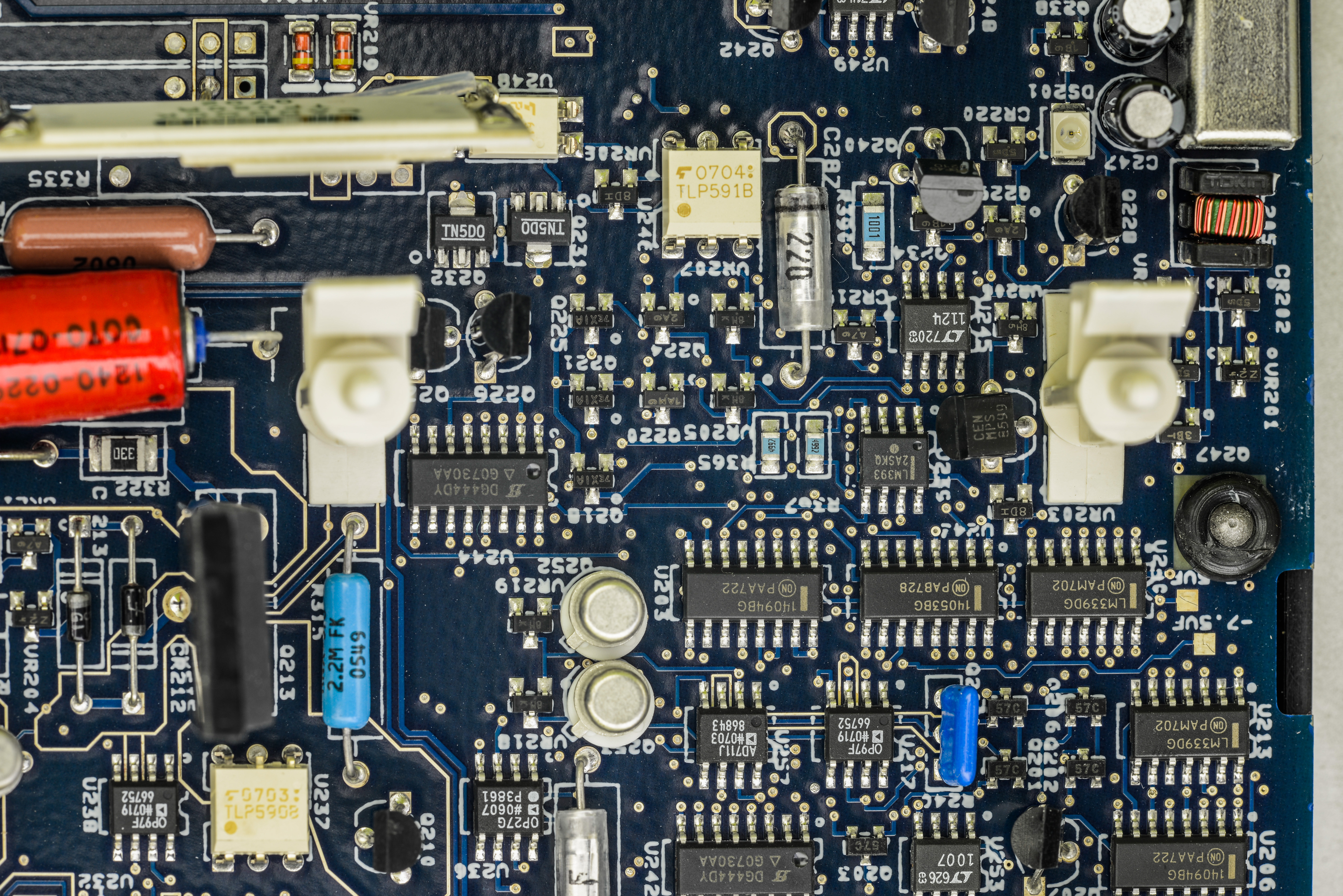
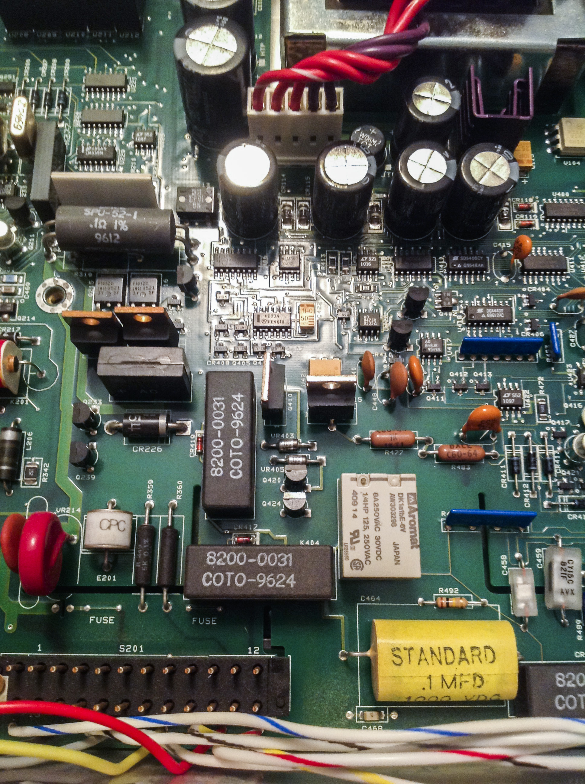
Mains switching / control curcuitry is same as in 2001. It handles selection 90-132 or 180-250VAC ranges automatically, as well as provide frequency zero-cross signal for ADC to trigger in right at required NPLC cycles, to increase CMRR and PSRR.
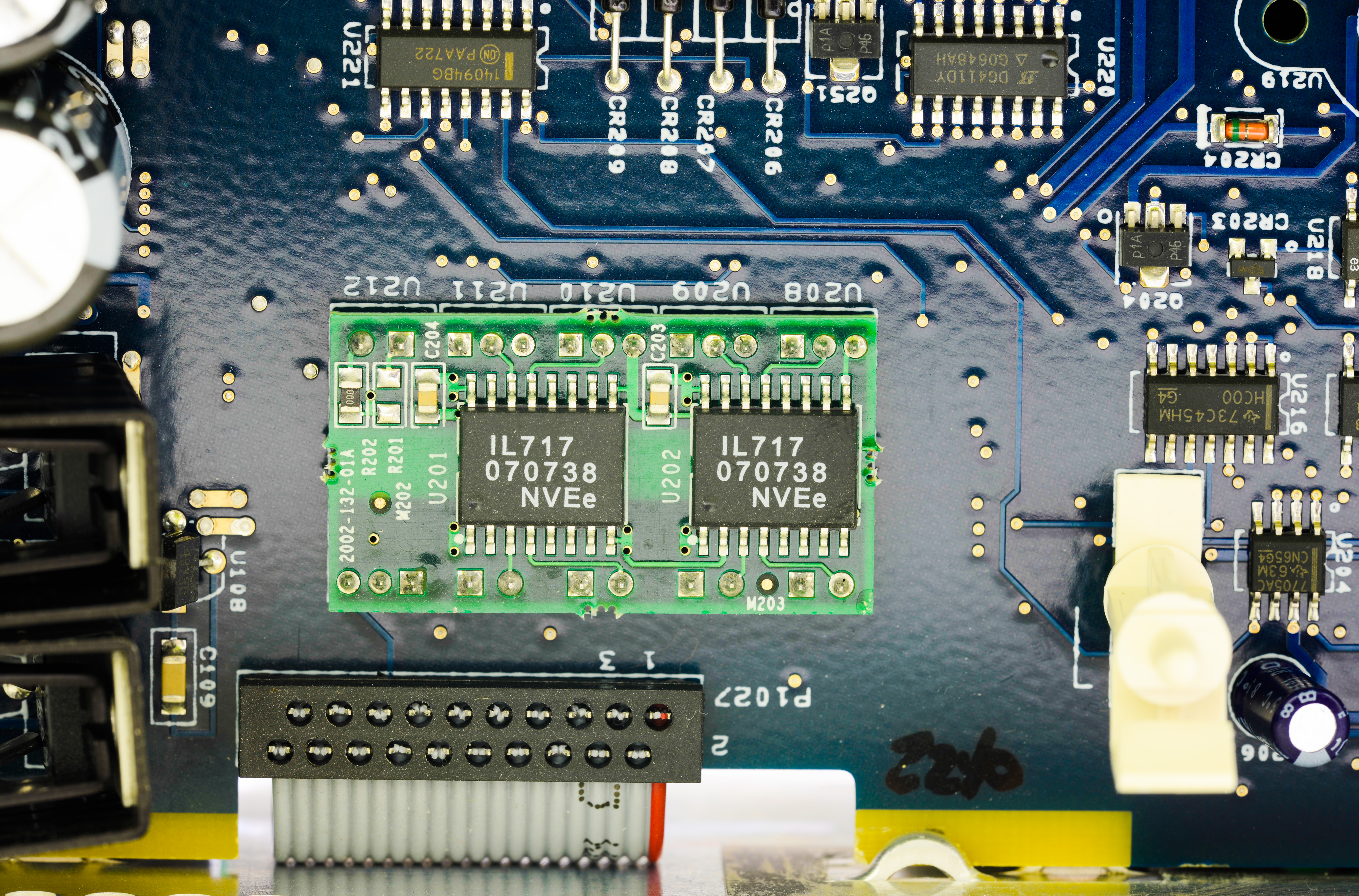
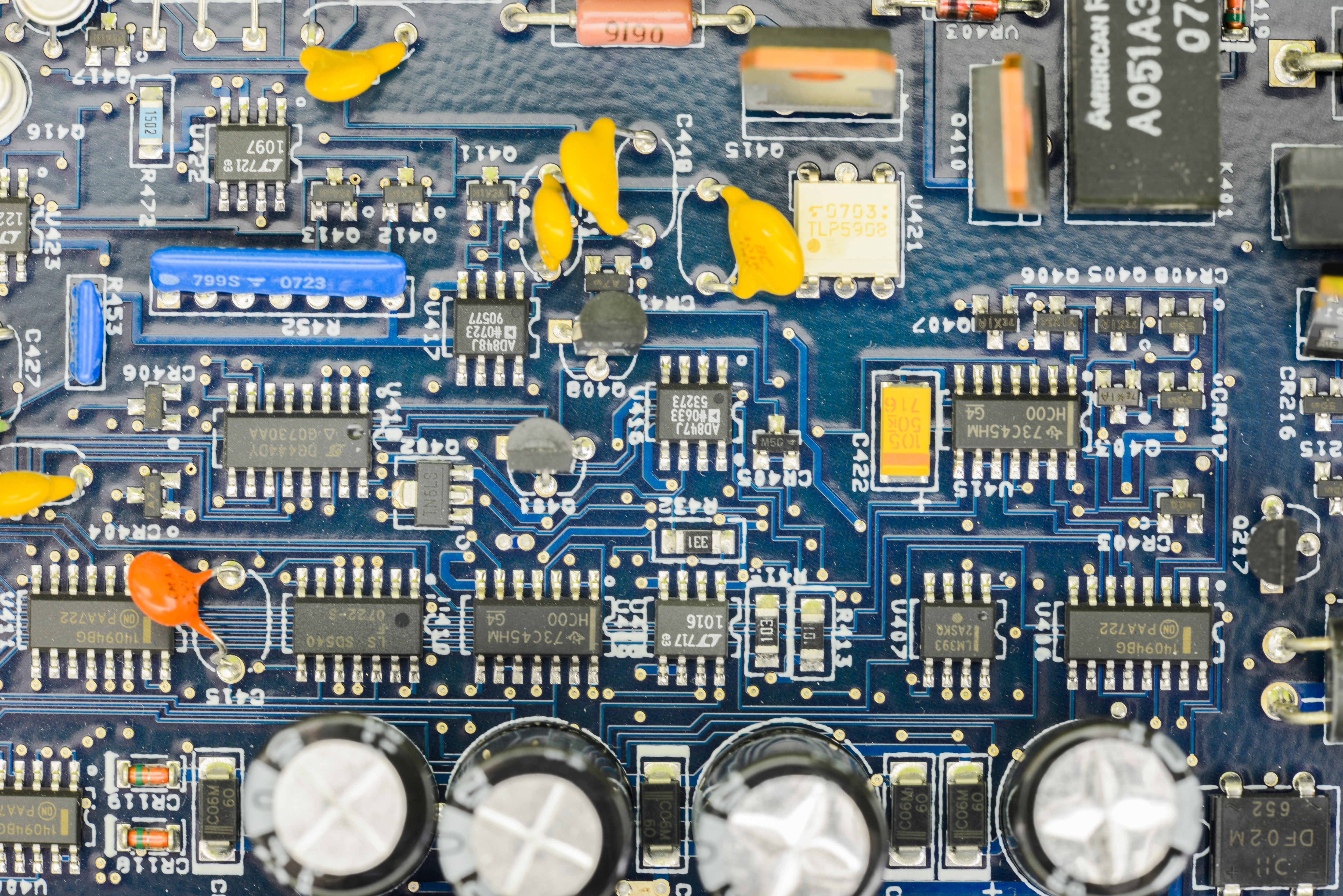
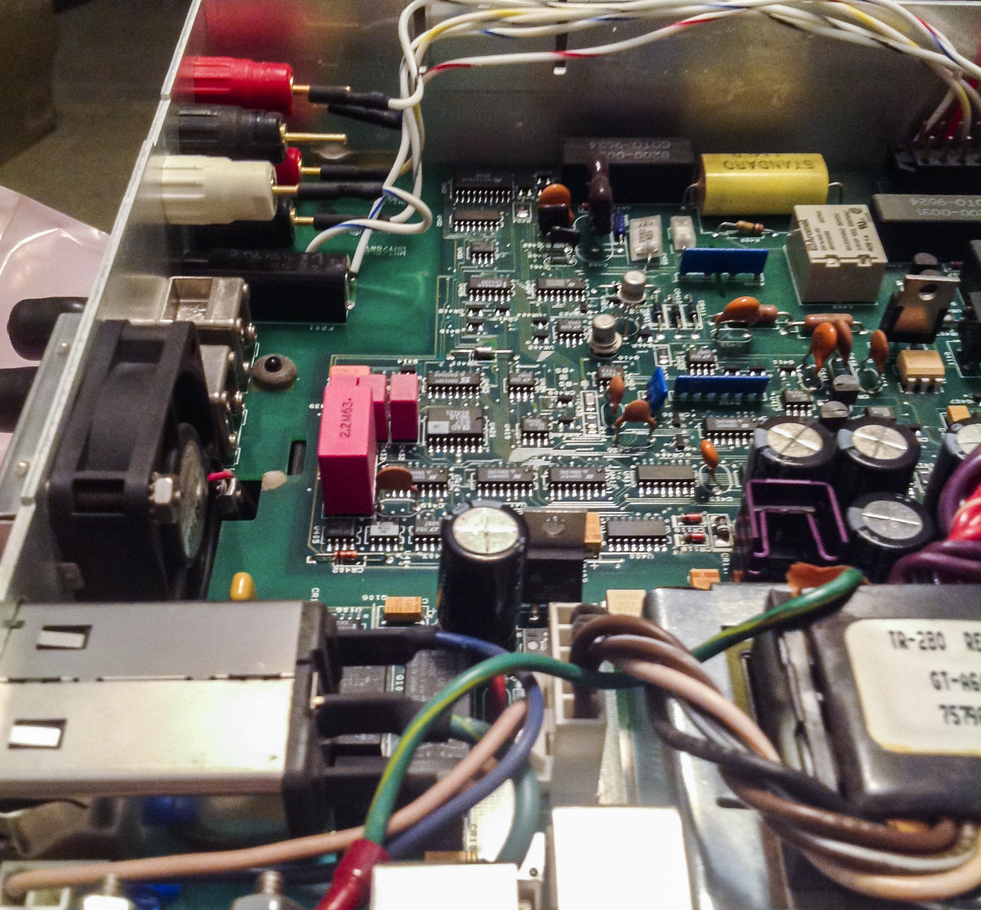
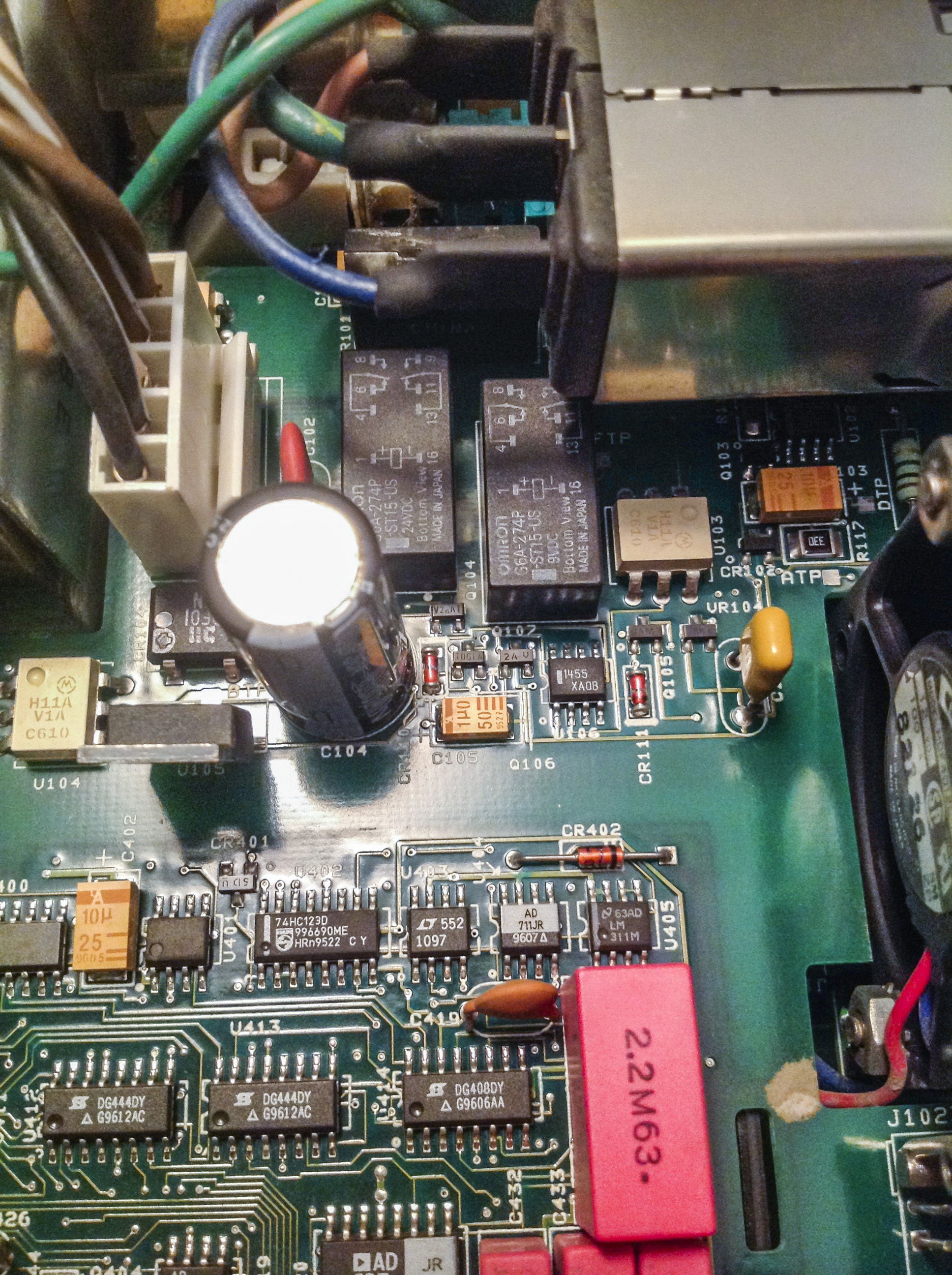
Optical isolation with digital board was done with separate daughterboard, labelled 2001-132-01A. It carry two NVE IL717, which are four-channel 110Mbps digital isolators. But if look closely – pin interface between boards matching original TLP582’s, so my guess that TLP582 couples were difficult to get in stock, so they added this adapter board, to keep analog board design intact.

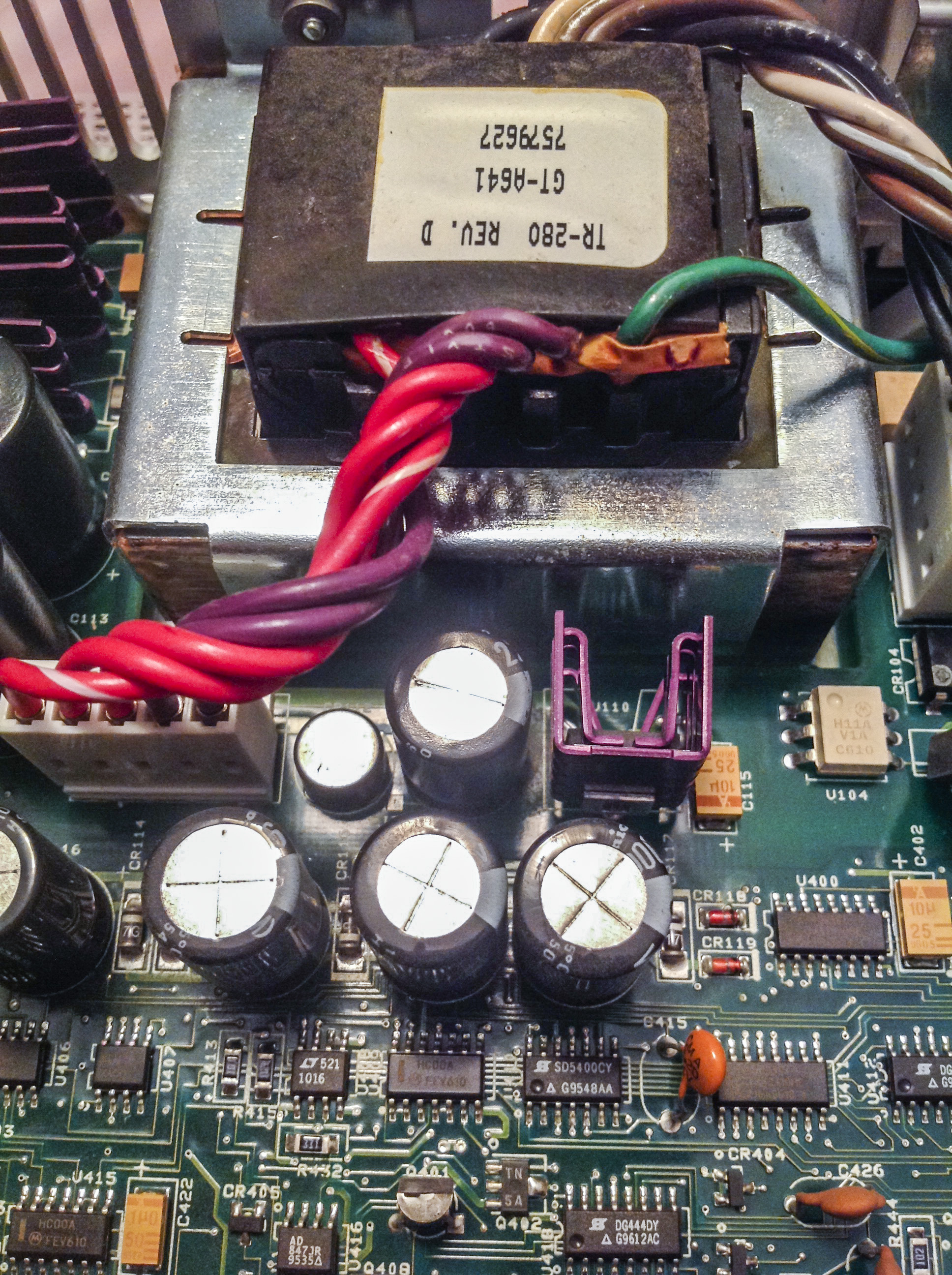
Power transformer have same configuration and pinout as 2001, marked HIREL systems, TR-280 Revision D. It have magnetic shielding with copper foil around winding.

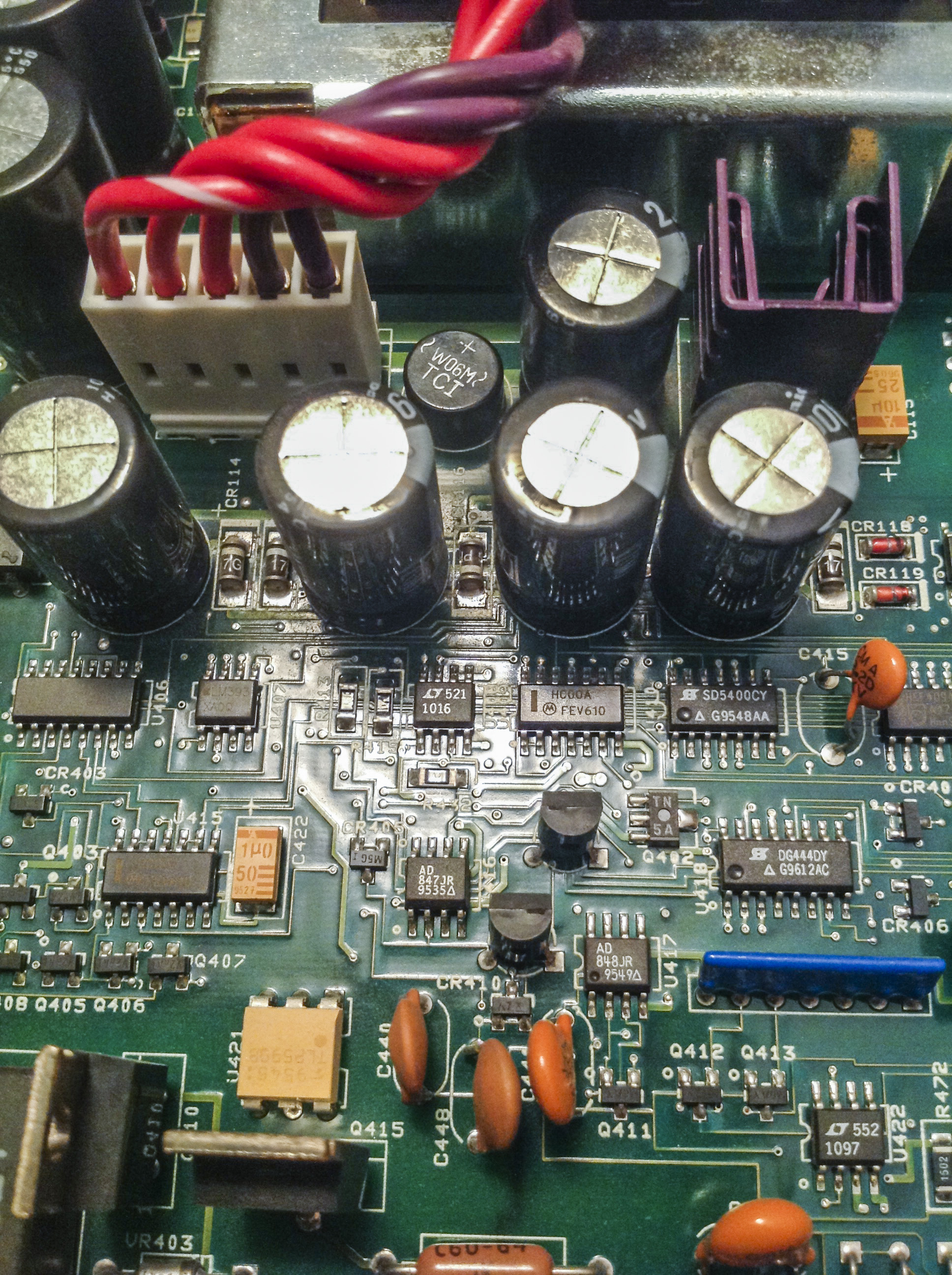
2002 equipped with very similar or same bootstrap circuitry, which provides +39 and -39V for analog needs, as well as +8/-8VF for ohm/amps measurements. Those pesky C116,C115,C118,C119 capacitors tend to leak with age/elevated temperatures and commit complete disaster on PCB, eating traces, leaking electrolyte all over precision circuits…
This meter is only 8 years old, so they are still fine, but next year I will replace them to freshies for sure :)
Input side.
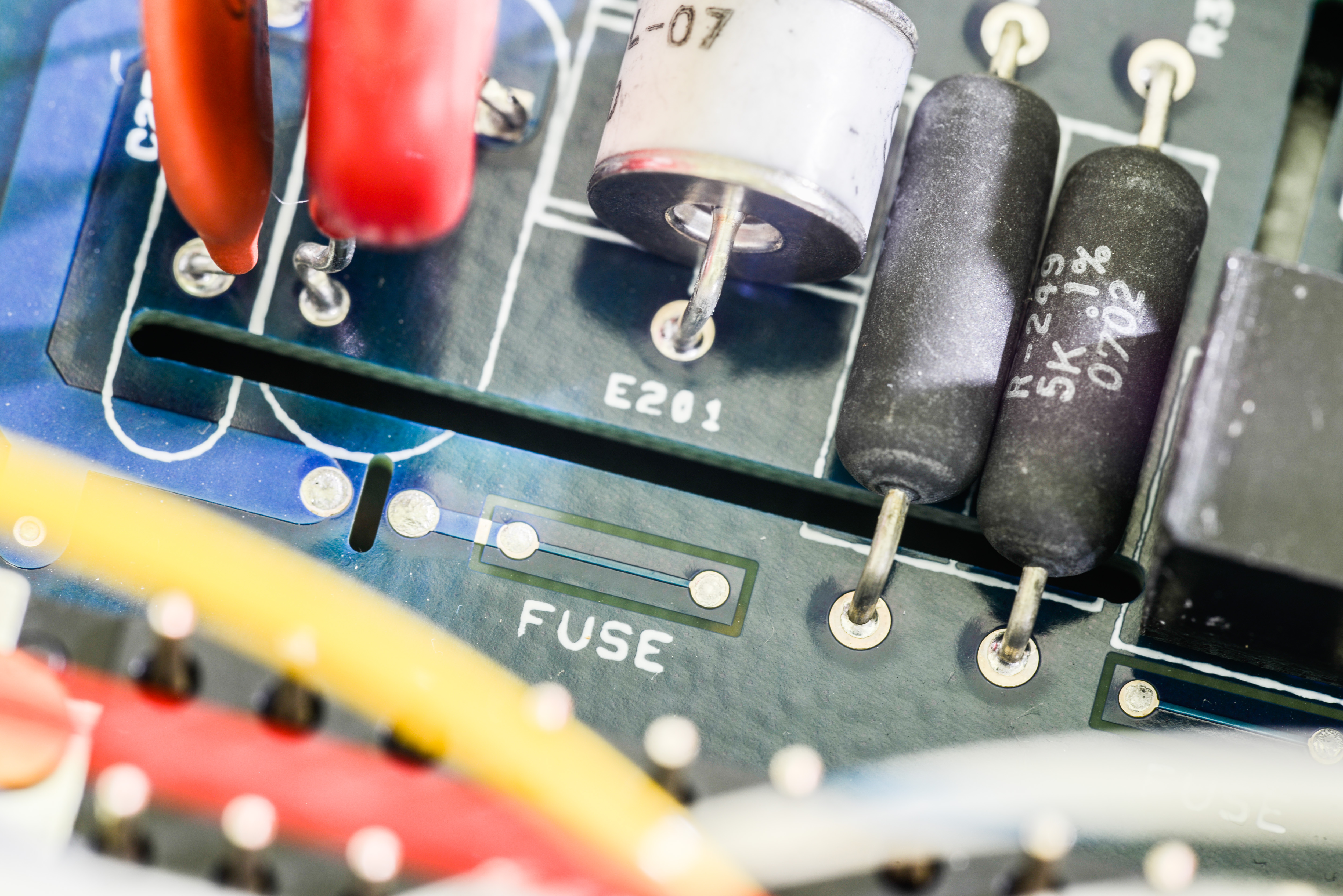
PCB Fuse :) Old 2002 analog board don’t have this, at least from what I can say looking on crappy photo from chinese forum mentioned before. 2001 also don’t have this. Wonder what that one does, maybe some last step emergency protection?
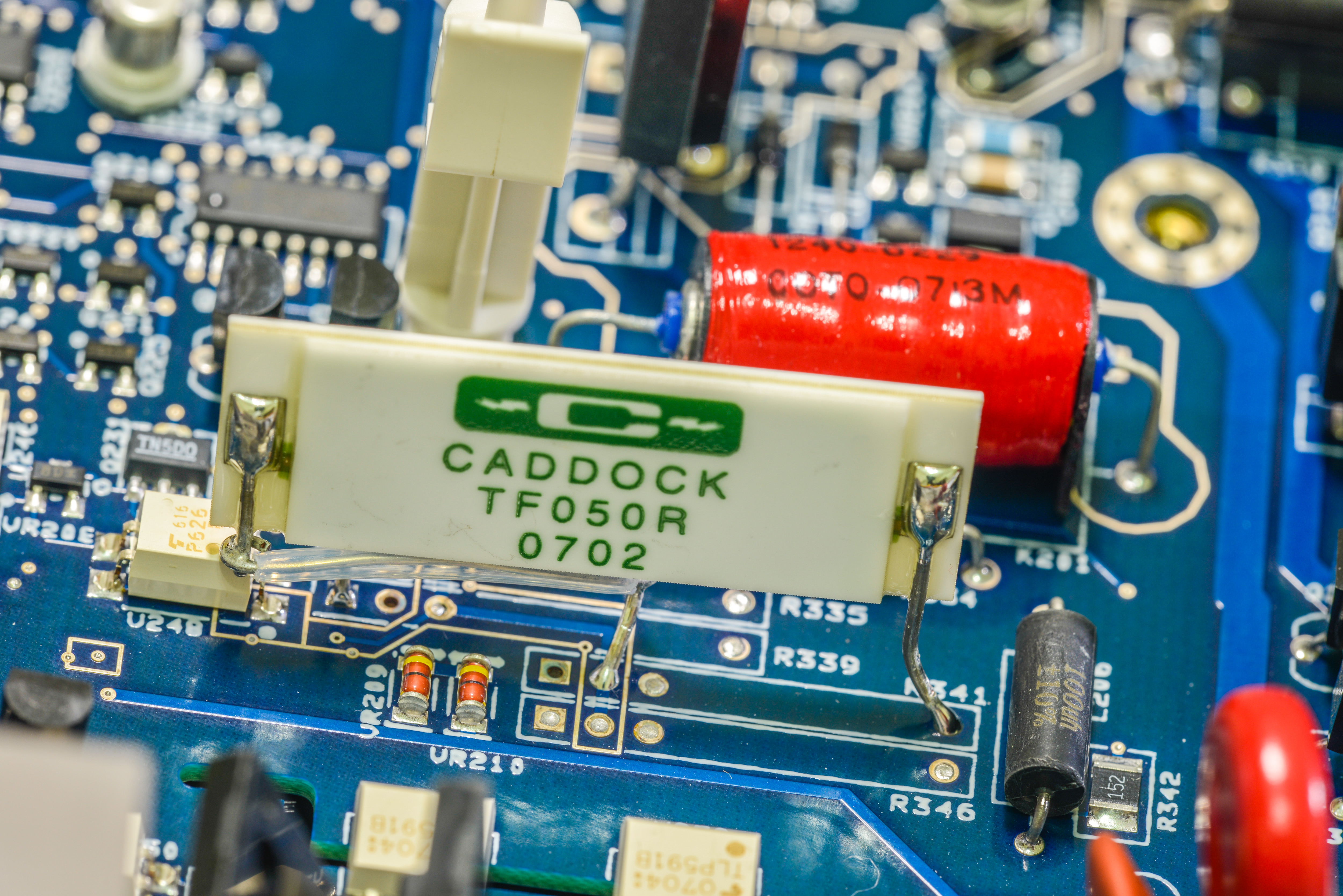
Combined Caddock resistor network.

Consists from two resistors, bigger TF050R, and glued TF020R on back of it.
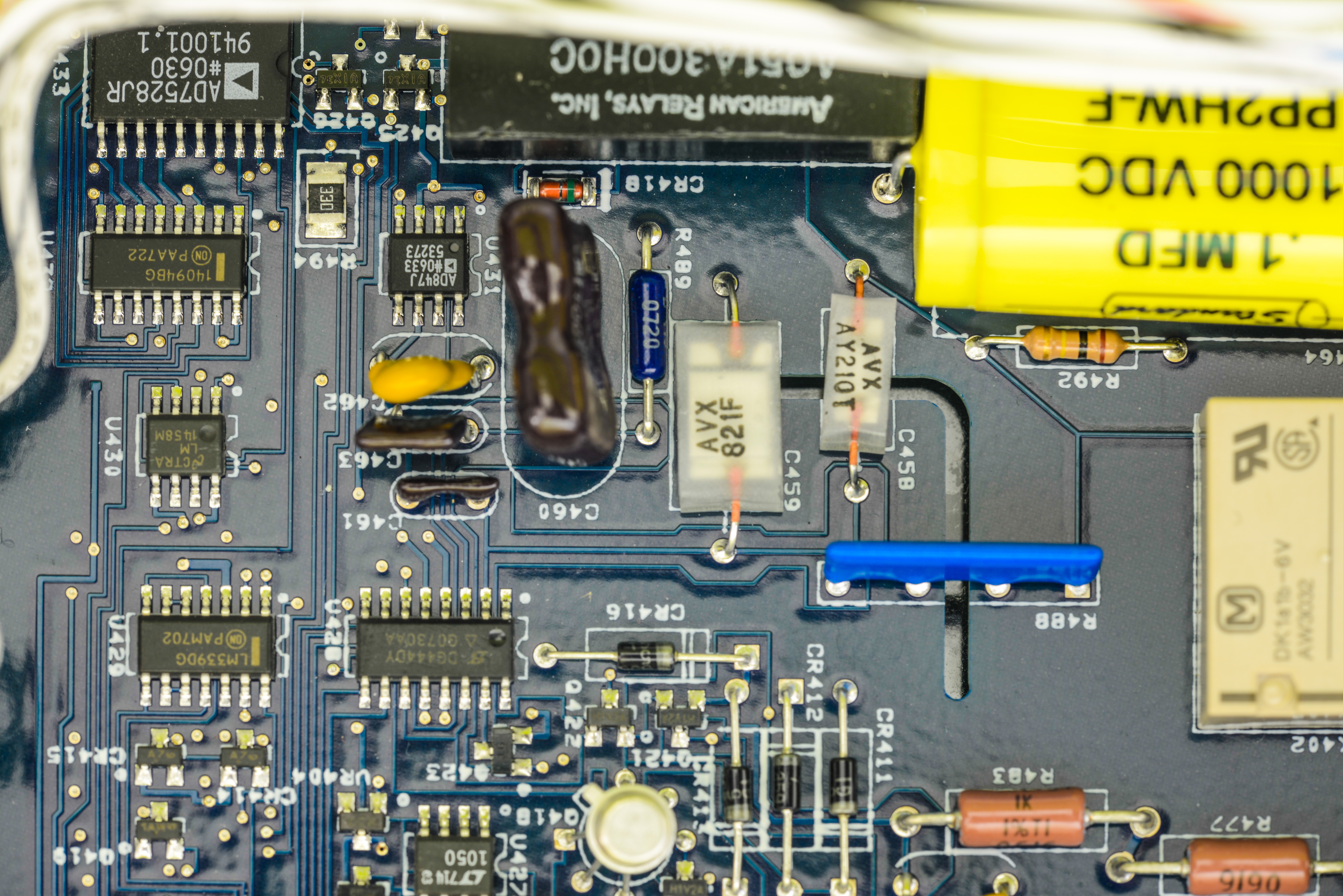
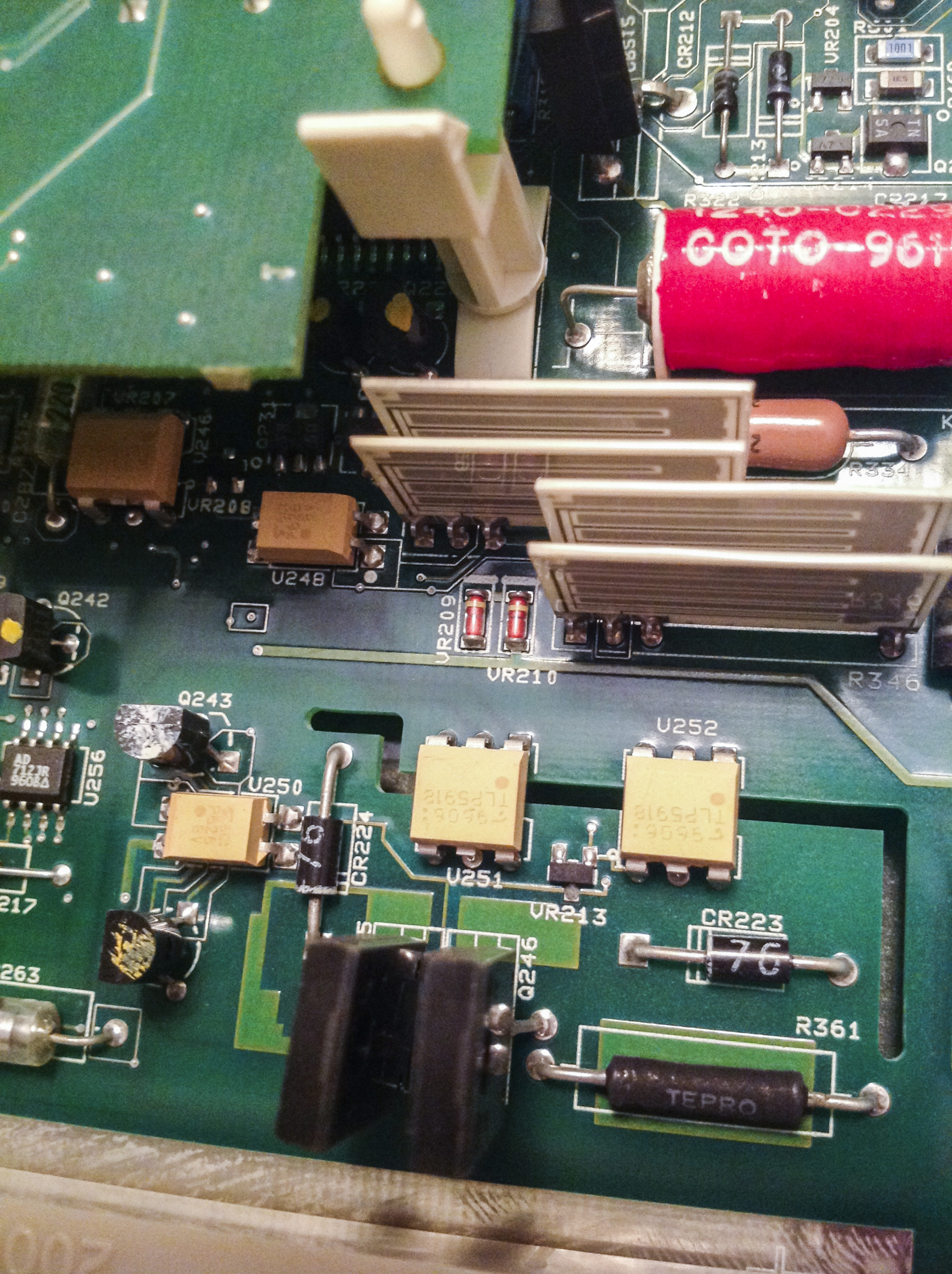
Reed relays made by Americal Relays Inc in this meter, A051A300H0C model, which likely to be custom, and usual DK1a1b-6V relay. Circut here same or almost same as 2001.
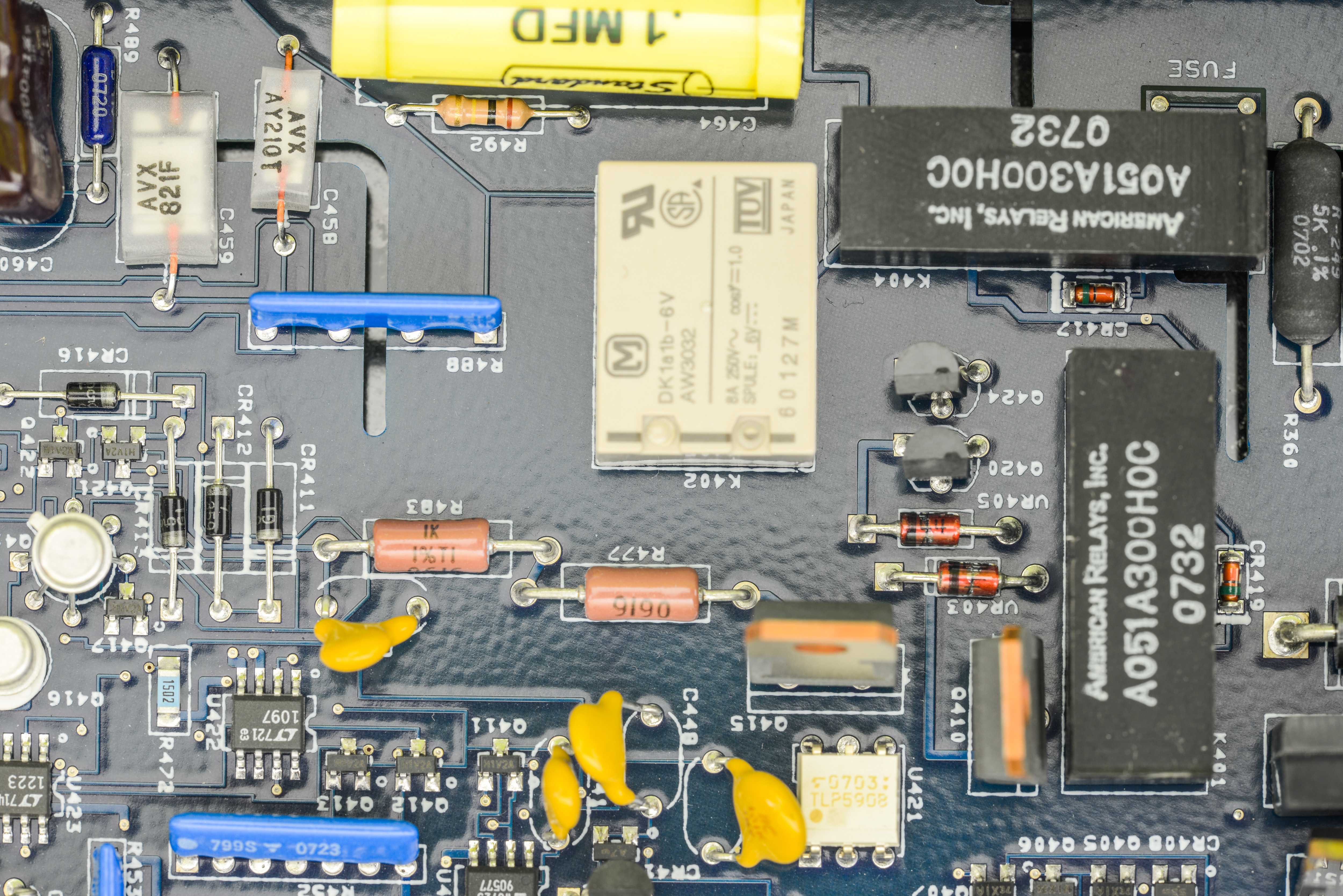
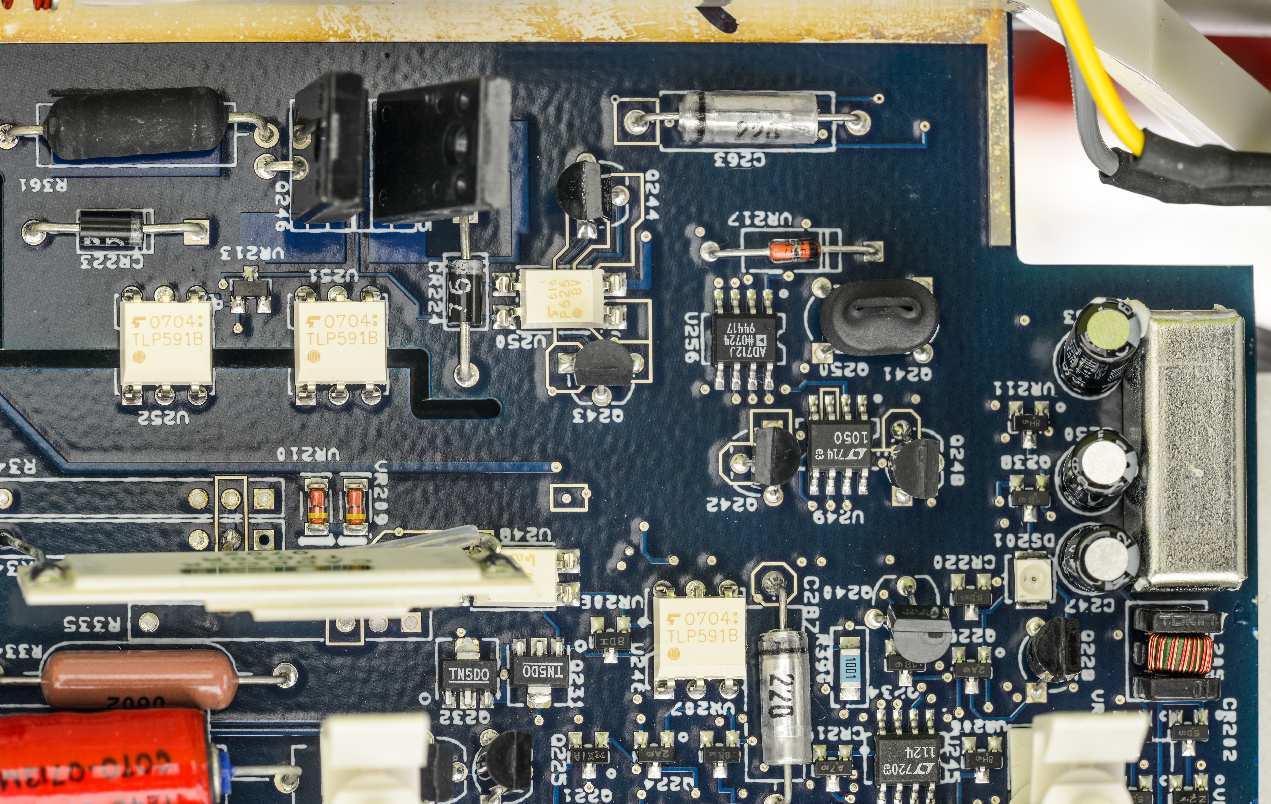
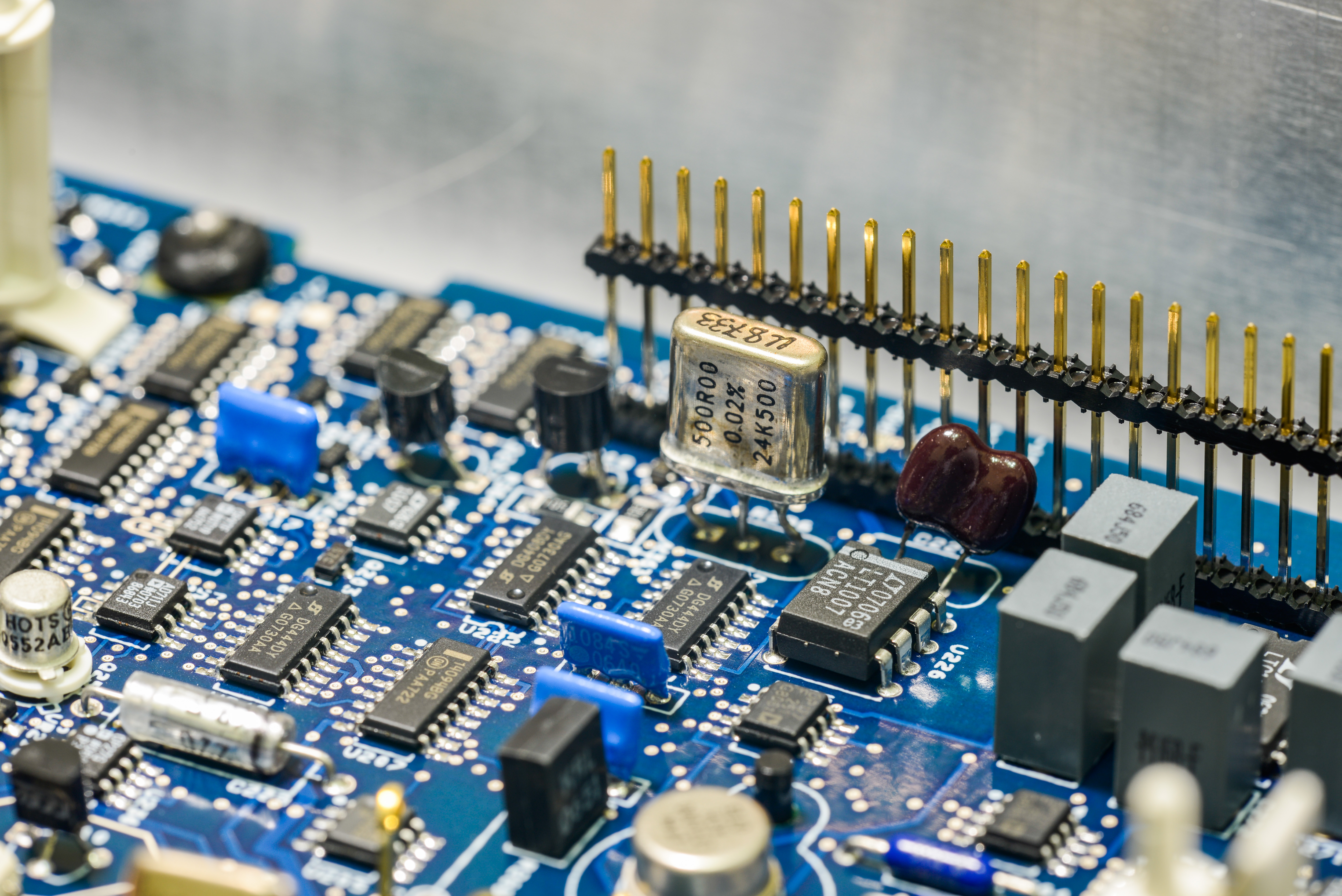
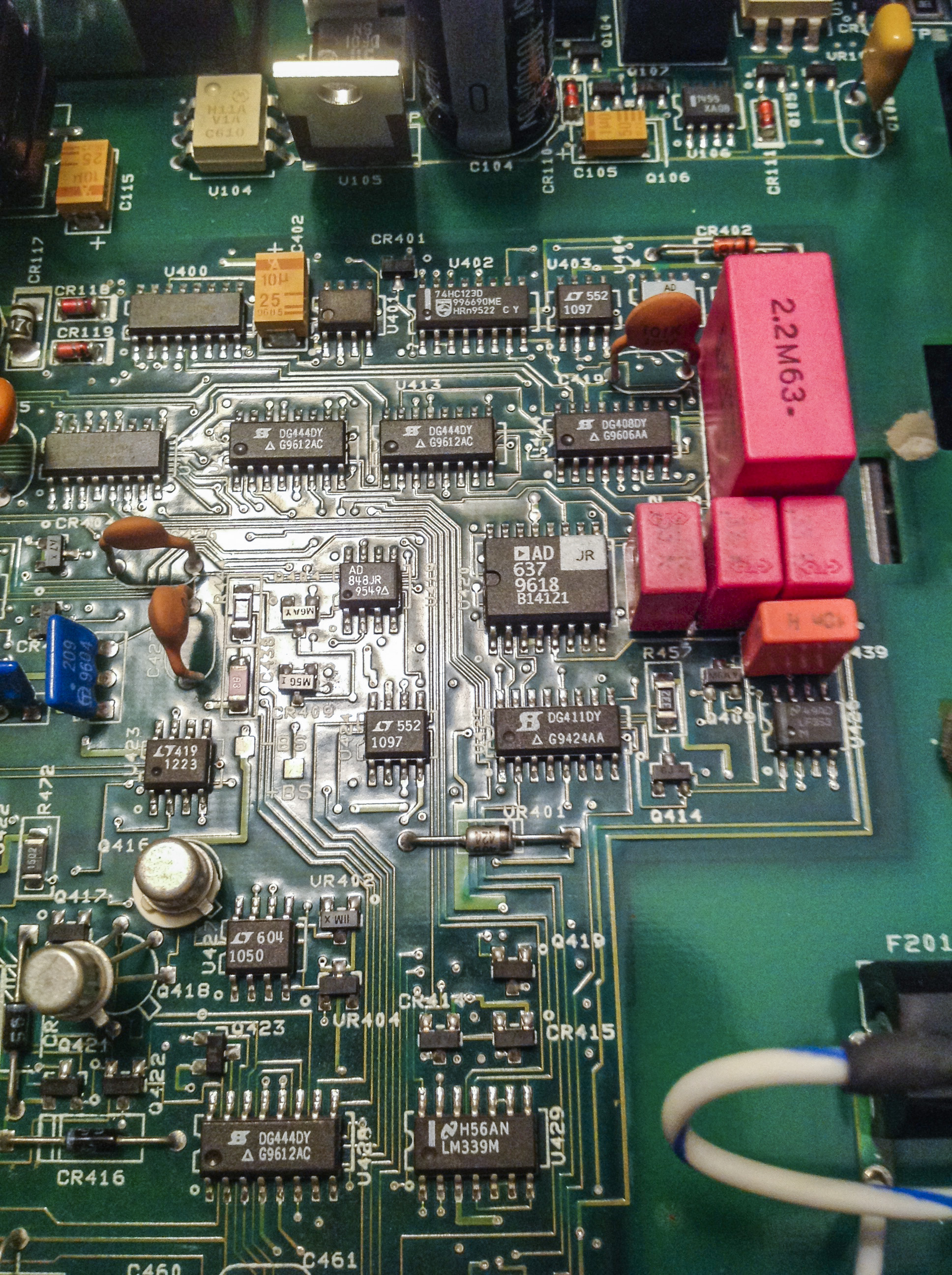
Old 8-bit DAC from 2001 meter (MP7528) got replaced by same thing, which is Analog Devices AD7528, dual matched DACs, which are used for TRMS filter circutiry to adjust operation of meter’s AC conversion block. This section is very similar or same to 2001.
Same with TrueRMS convertor itself, which is AD637JR with bunch of DG444,DG408 and DG41 switches around. There are also AD848J, LT1097, LT1223, AD711J and LM79L05A -5V negative LDO in this area. All same stuff as 7.5 digit Keithley brother.


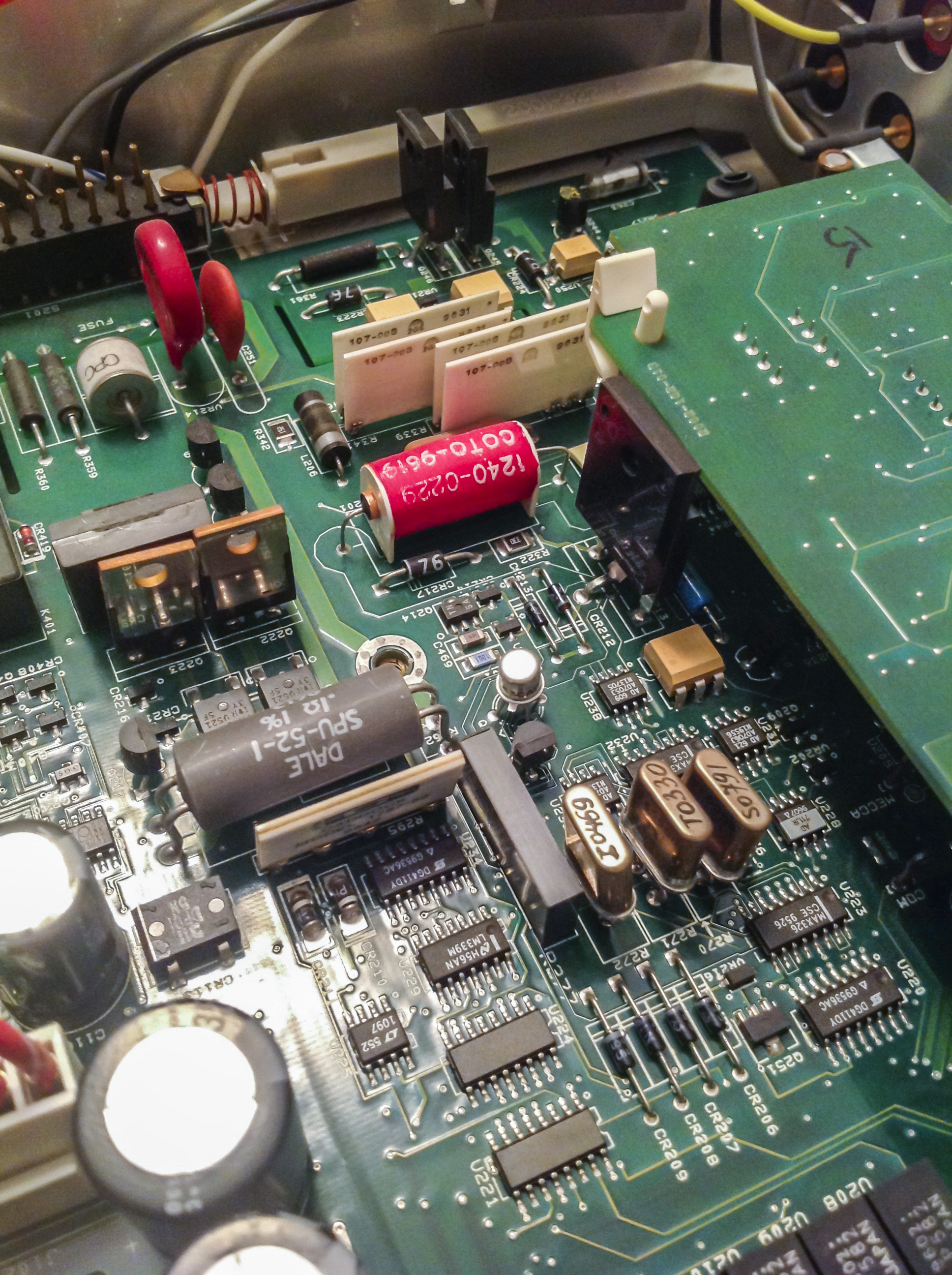
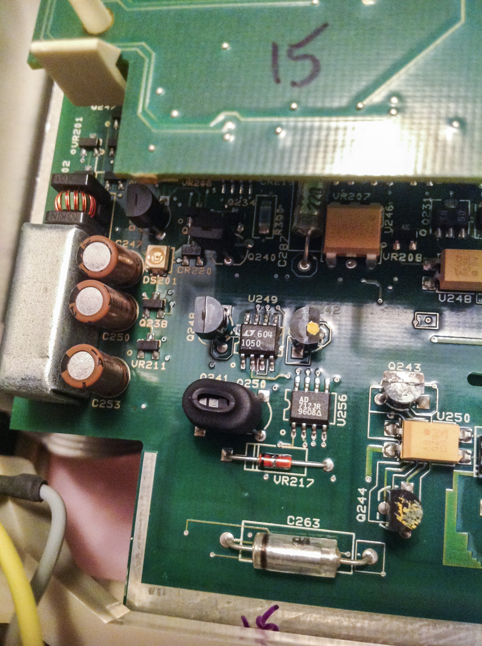
Primary ultra-stable +7V VREF:
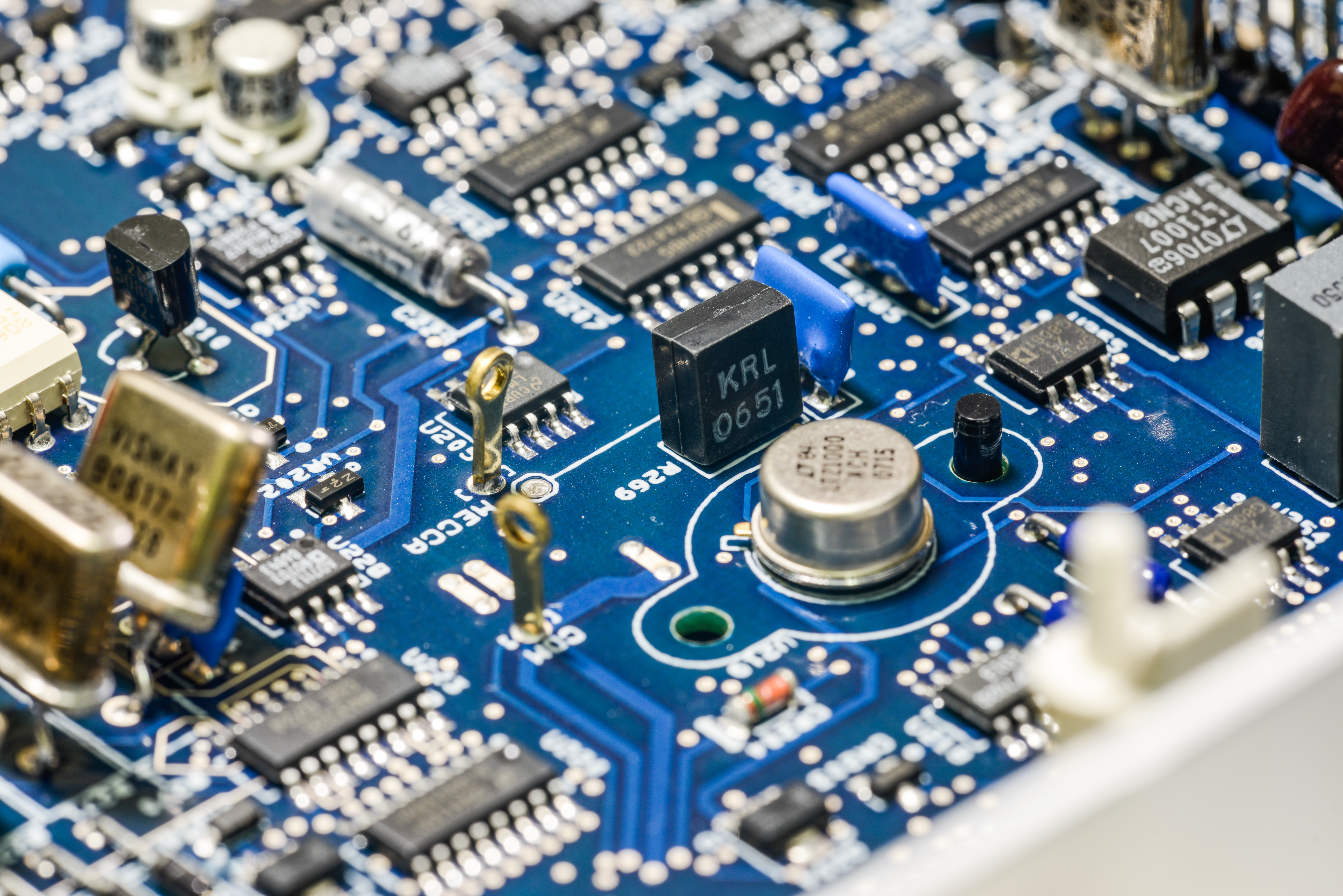
Famous Linear ultra-zener reference, LTZ1000.

It have dedicated plastic cup from both sides of to seal reference from any airflow and reduce temperature influence from rest of the world. Probably it’s reference standard connection, can see 120 ohm 0.1% resistor nearby, as well as few PTF56 low-tempco resistors. Also two blue resistors networks nearby, but those may not be related to voltage reference, at least one of such networks can be found in 2001 too.
Back side of PCB with LTZ.

LTZ have popular companion Linear LT1013 in SO8 package with Q204 is heater drive transistor in SMT package.
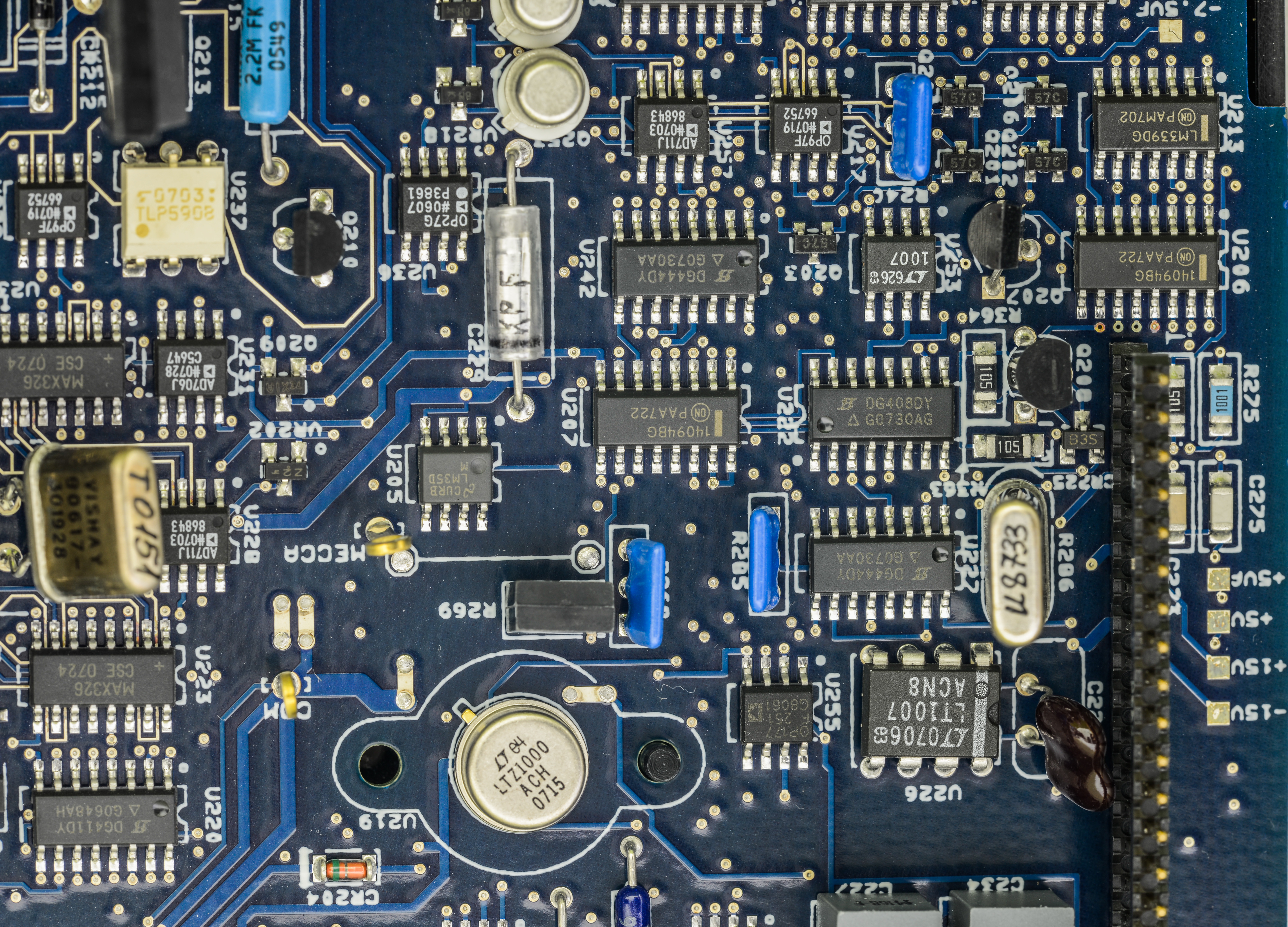
There is also temperature sensor somewhere on board, as Keithley 2002 can measure it’s internal temp, which it reports as delta to calibration temperature. This measurement is readily available by temperature function, by selection INTERNAL TEMP mode. In my case, reported value was -3.4°C , with ambient temp +24°C, while meter run around half-hour. If I just power on cold meter it says -23.2°C and descreasing (to lesser delta) while meter warms up.

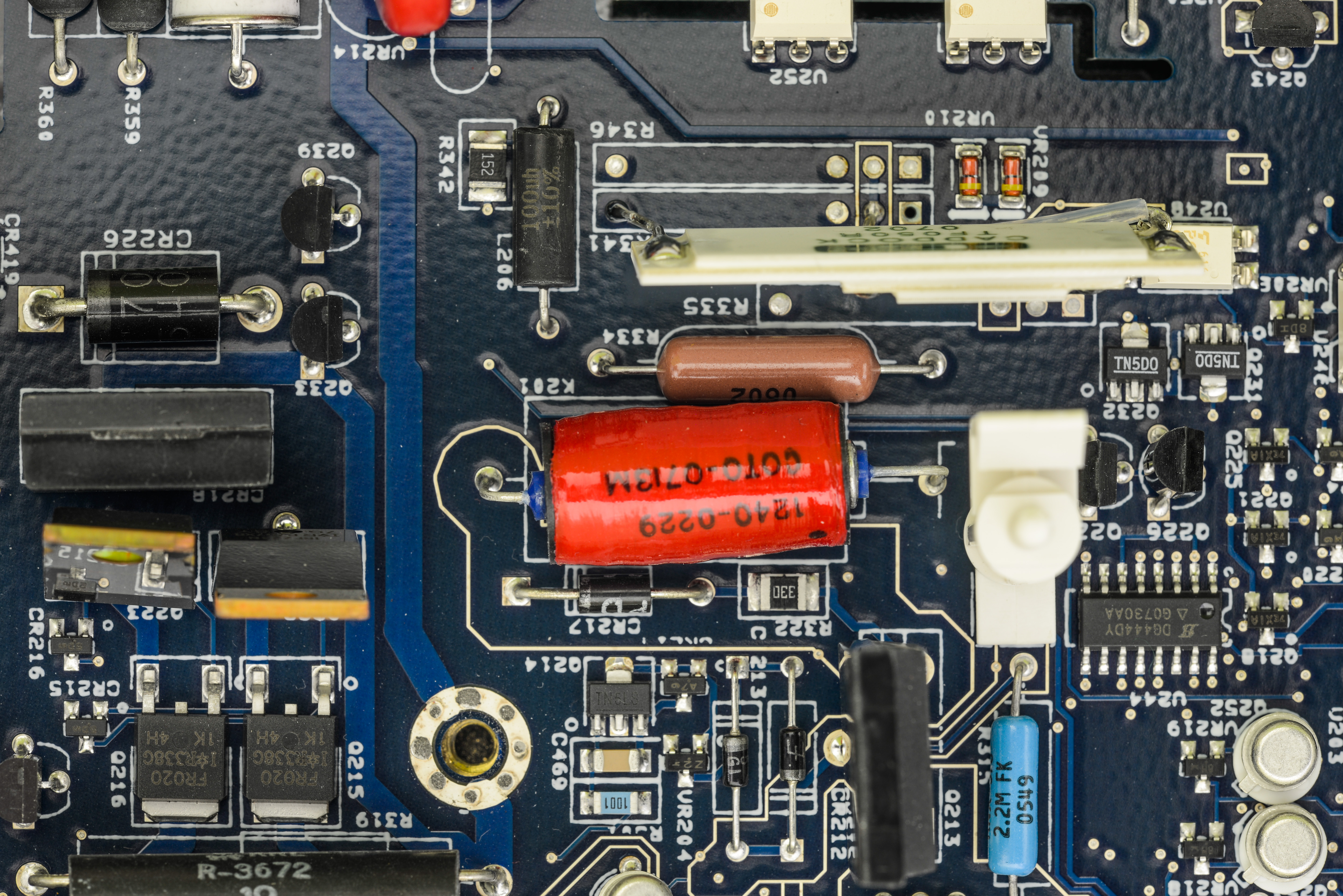
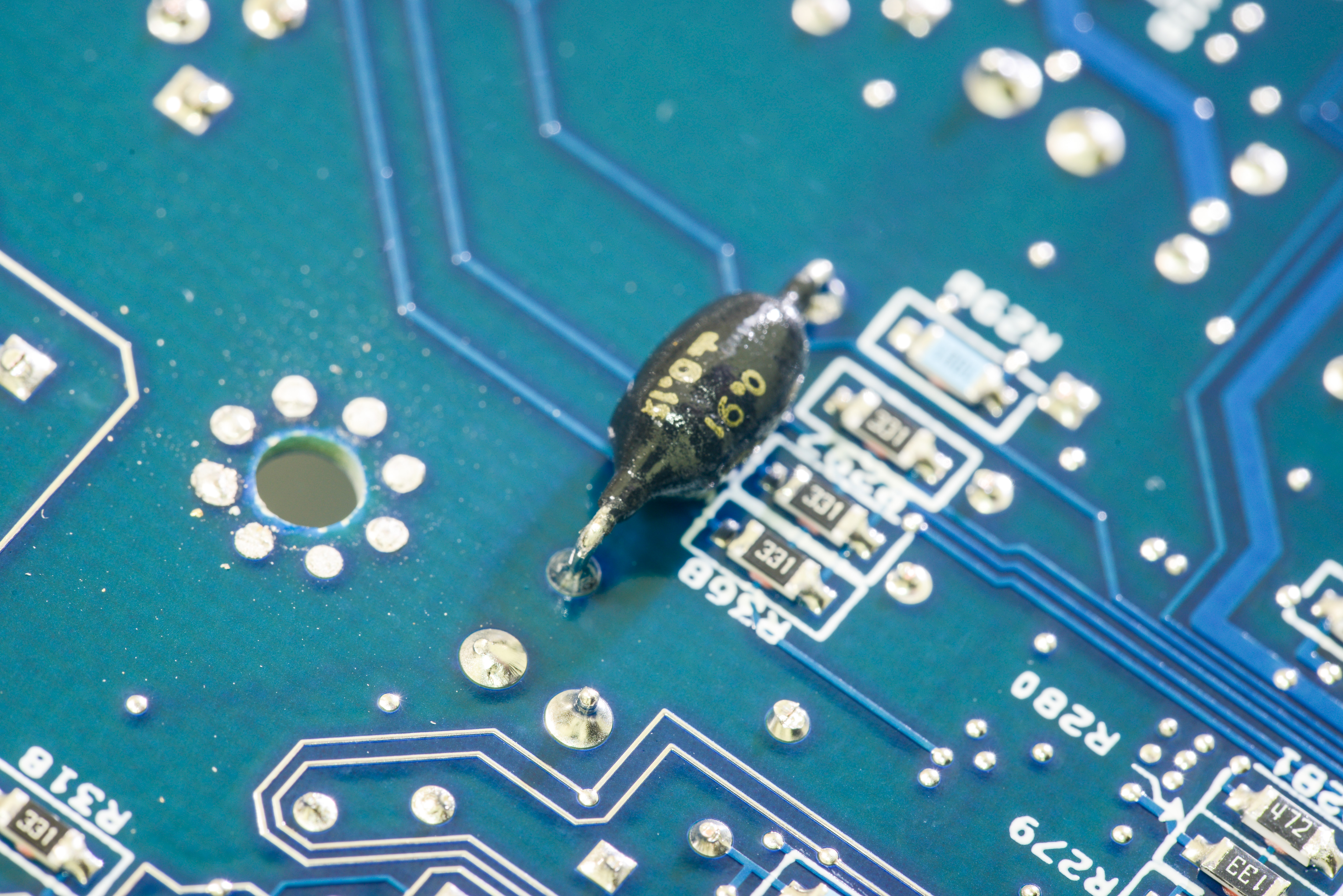
Current measurement parts, two MOSFETs to switch ranges for high amp ranges, long Vishay Z201 resistor (R277).
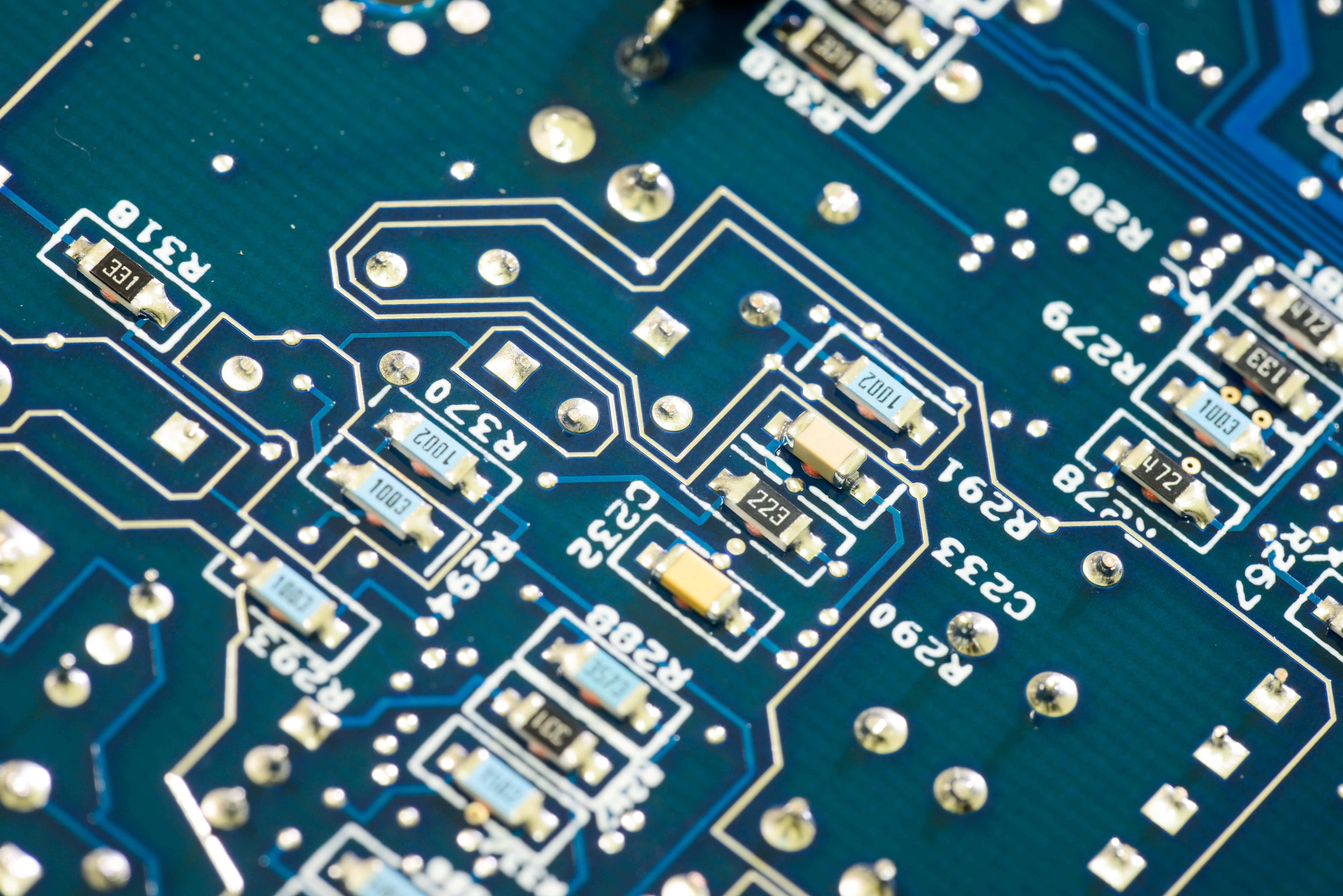
Right side of photo is for resistance measurements.
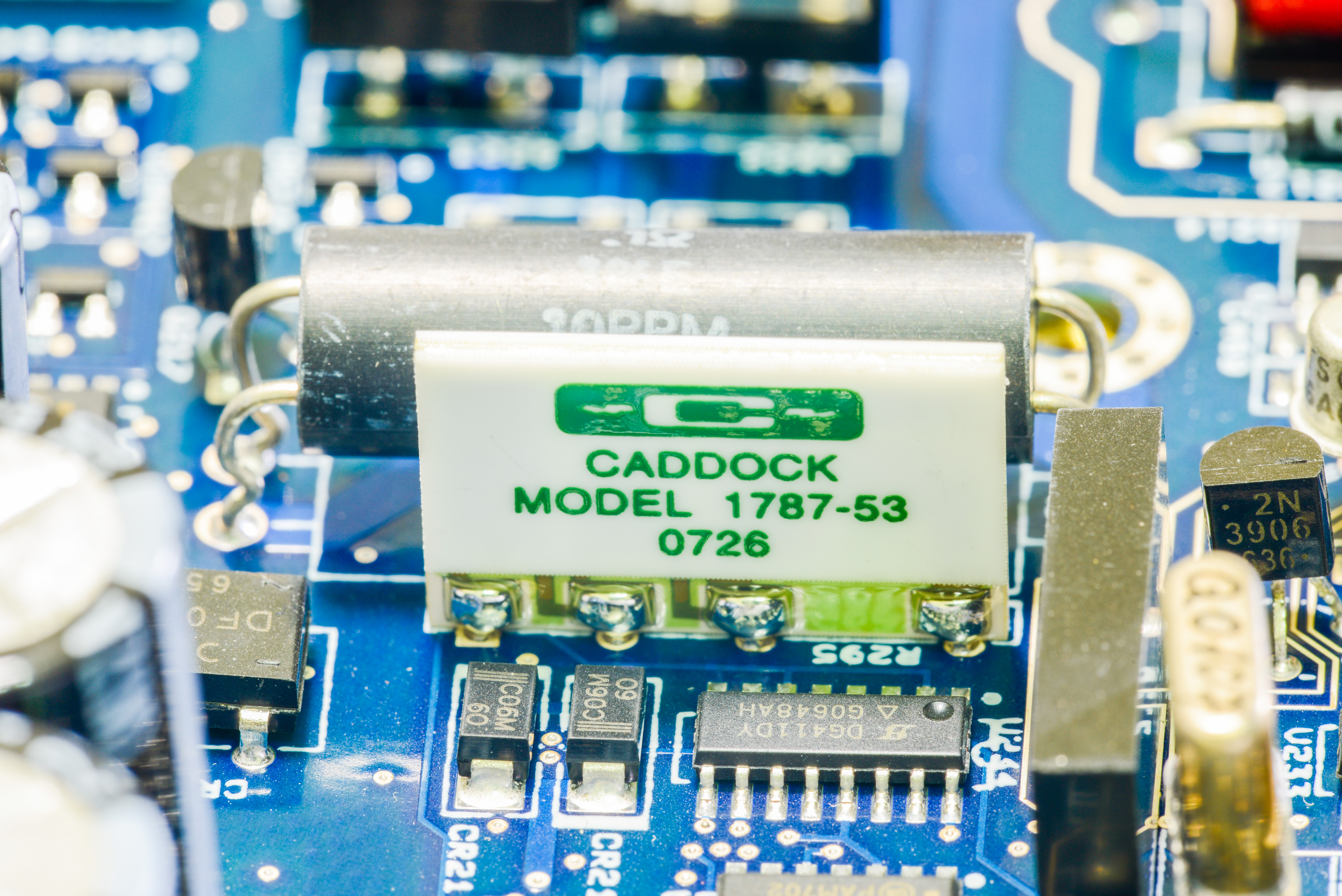
Same CADDOCK as in 2001 for low current ranges. This is actually standard network 1737-53, available even on Digikey :)
And not so standard Vishay PG hermetic oil-filled bulk foil resistors, with tolerance 1%. Absolute tolerance is not so important in this case, as it’s software calibrated anyway, but stability and tempco is what needed most. And there are only few resistors on market which are better than these.
Resistors here used to set precise currents for sourcing thru unknown resistance for measurement. Switching is done by MAX326’s nearby. All heavily guarded and carefully designed precision voodoo.
There is also lonely Vishay PG hermetic oil-filled resistor network with tolerance 0.02% and 500.00 + 24500 resistances in it, likely setting gain for buffer amplifier (which is LT1007ACN8 in DIP8 package nearby). Switching of different gains done by DG444 and DG408 switch IC’s nearby.
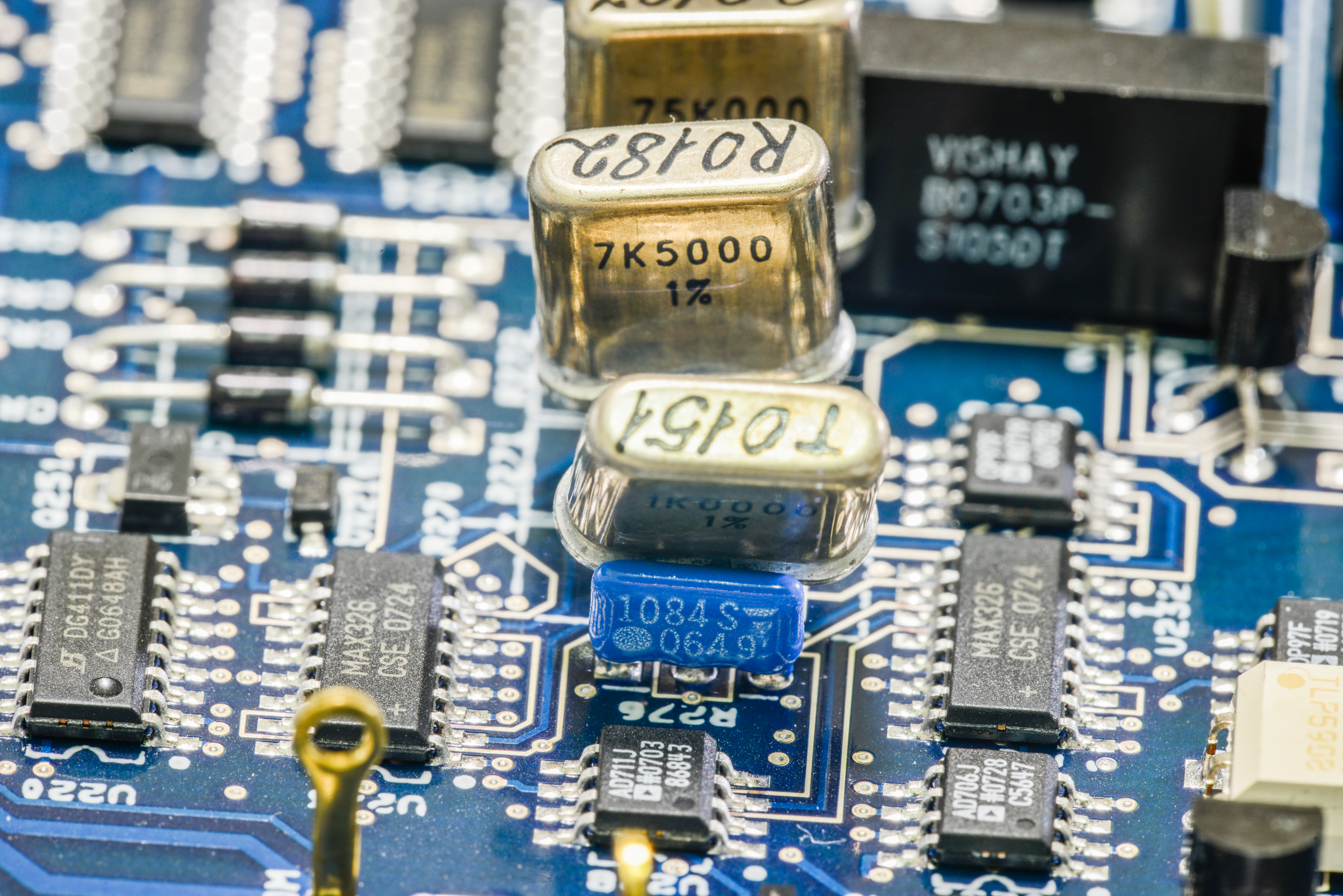
Circuit block around Linear LTC1043 are precision flying capacitor ratio generators, which are taking stable +7V from reference and generate secondary references used in meter. One of these is doubled 14V for resistance function operation. Second is divide by 4 to get ~1.8V for low ranges ADC conversions. These circuits have very low temperature coefficient and are quite stable blocks.


Switching capacitor dividers/multipliers, using film KEMET capacitors and Linear LTC1043CSW blocks. Keithley 2001 meter have only
one LTC1043 in DIP package.
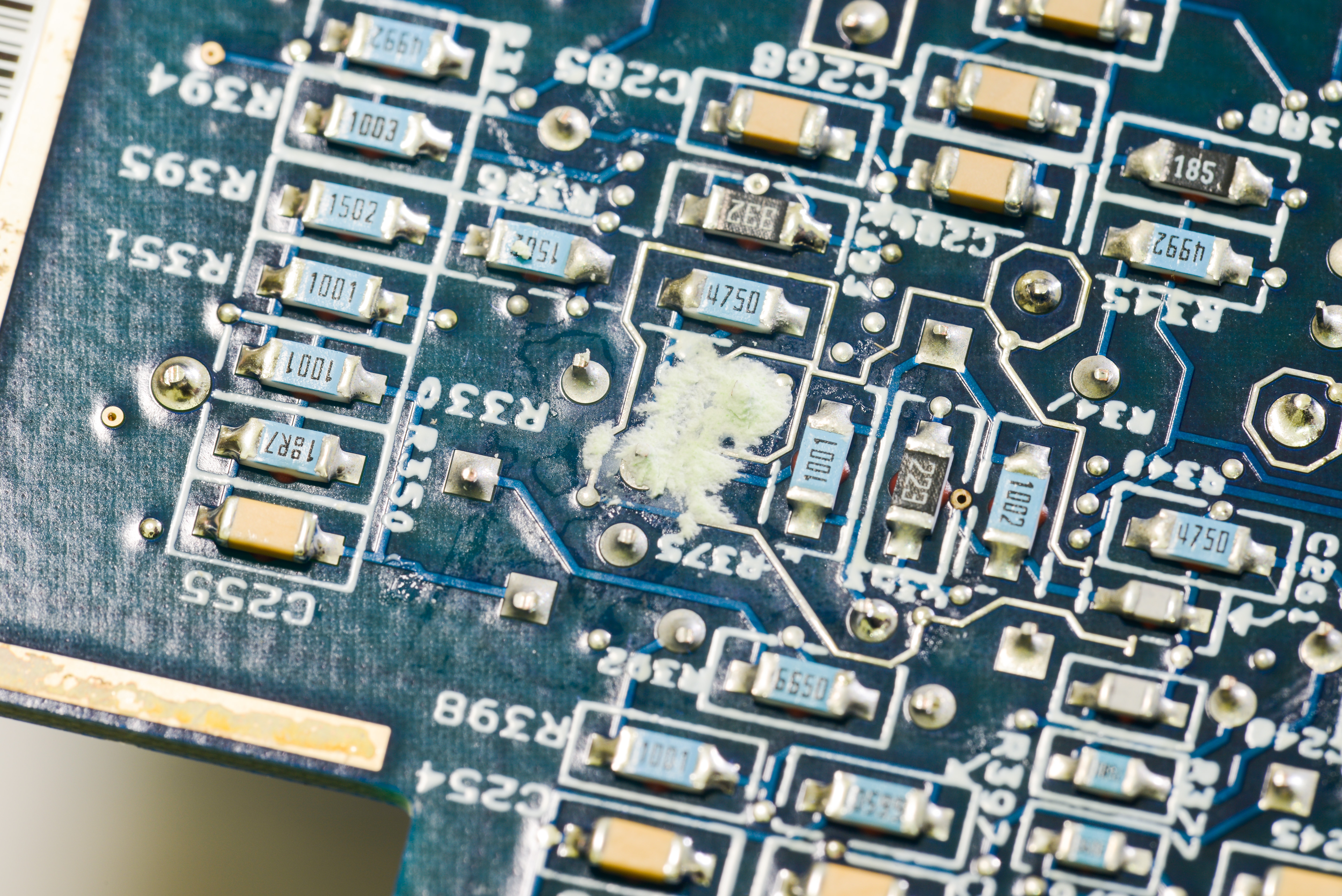
Blob in center look like corrosion/salt, and I actually cleaned it carefully, but that was waste of time. Why? Because it is from insulator sponge, placed on protective/shielding/thermal bottom cover.

More bottom side components.
0.91 Ω current sensing resistor shunt, unlike 2001, here its populated on bottom side of PCB. On 2001 it was right under 4-wire
resistor.

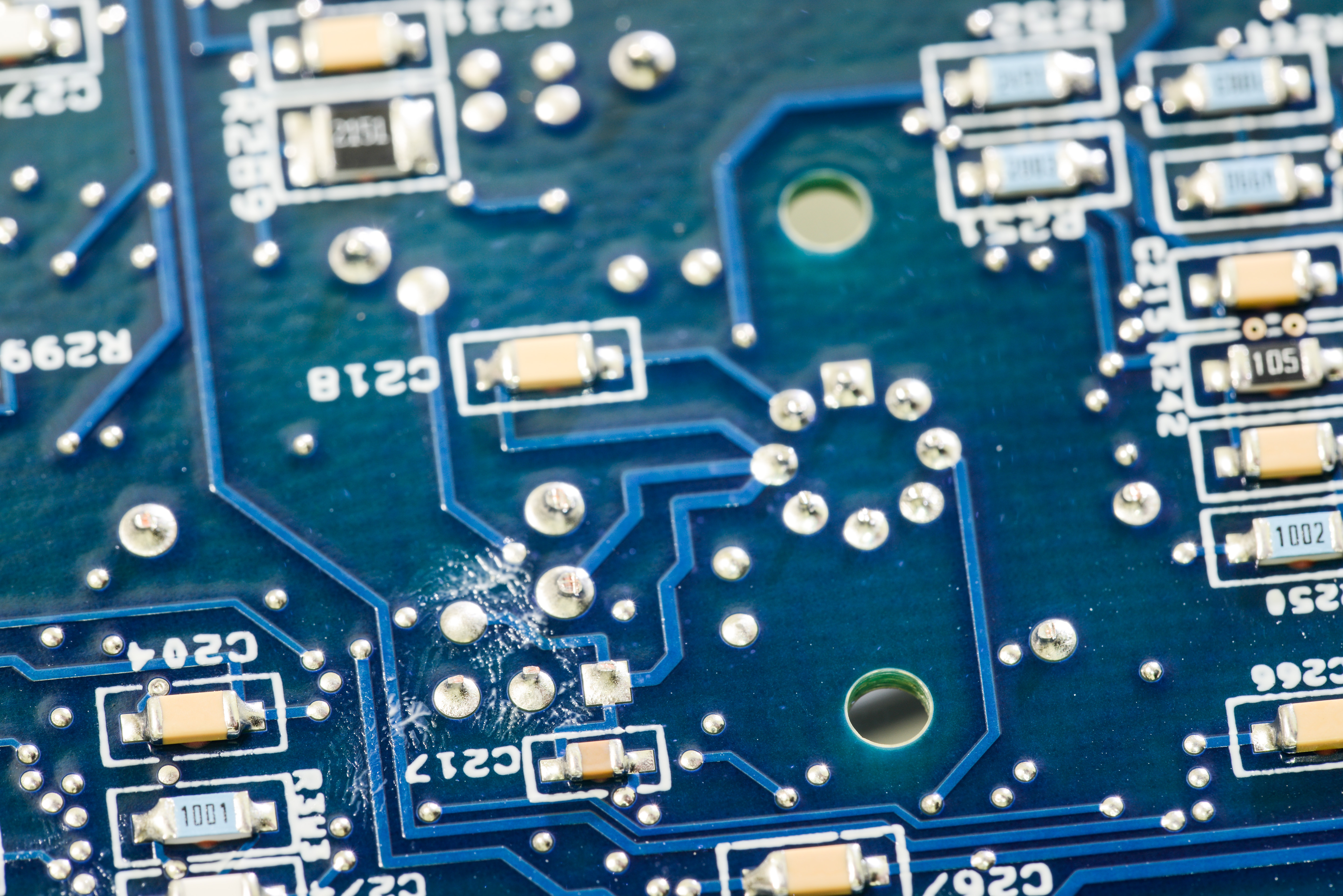
Those smudges/fingerprints seem to be on soldermask, as they are not erasable with alcohol. Looks dodgy, but it seem
not affecting performance..
Dual guard traces around sensitive high-impedance resistance measurement circuitry. Beauty!
Overview of bottom side of analog board, without cover.
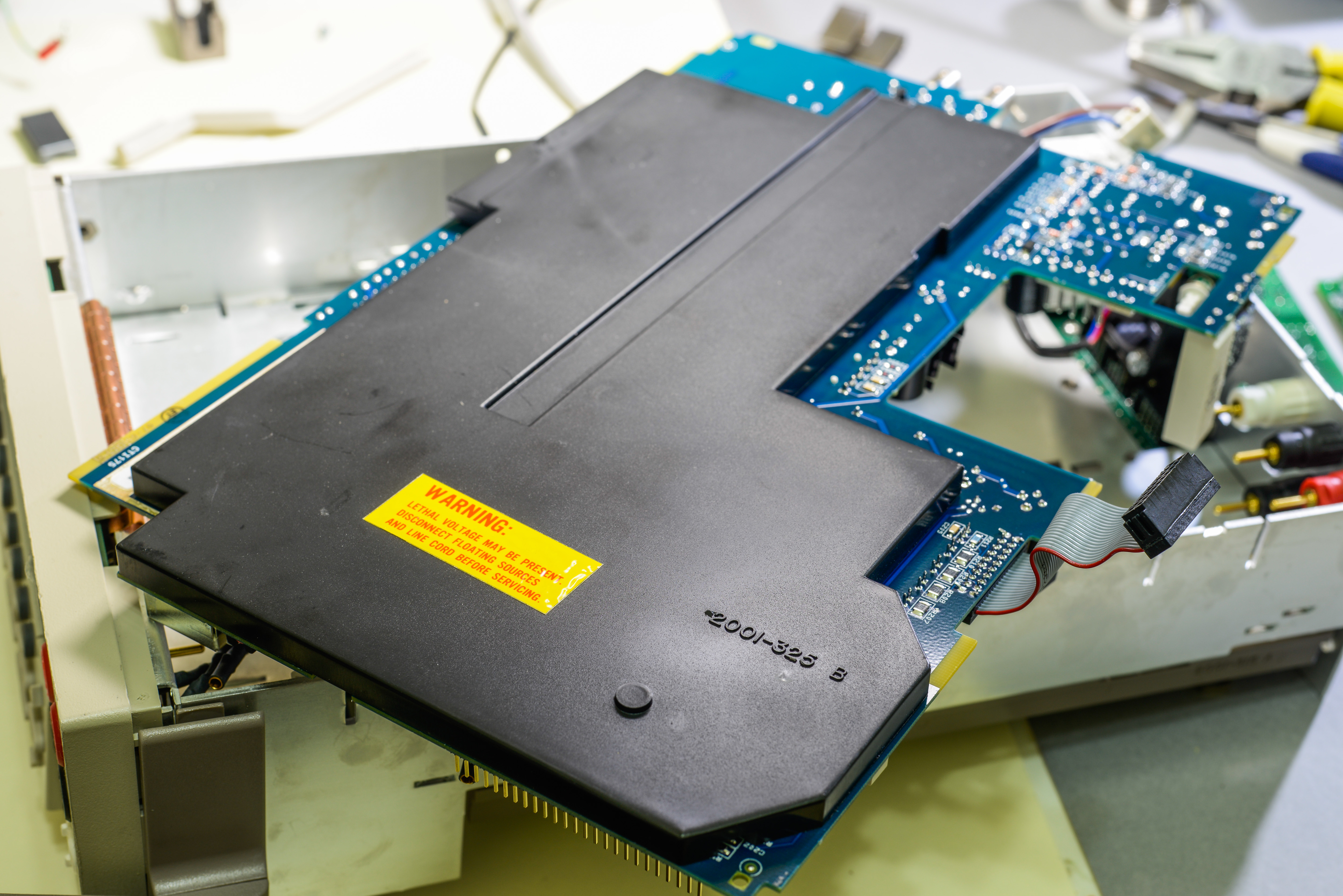
Back cover/shield is same as 2001’s, and actually bearing 2001-325 Rev.B tag on it.
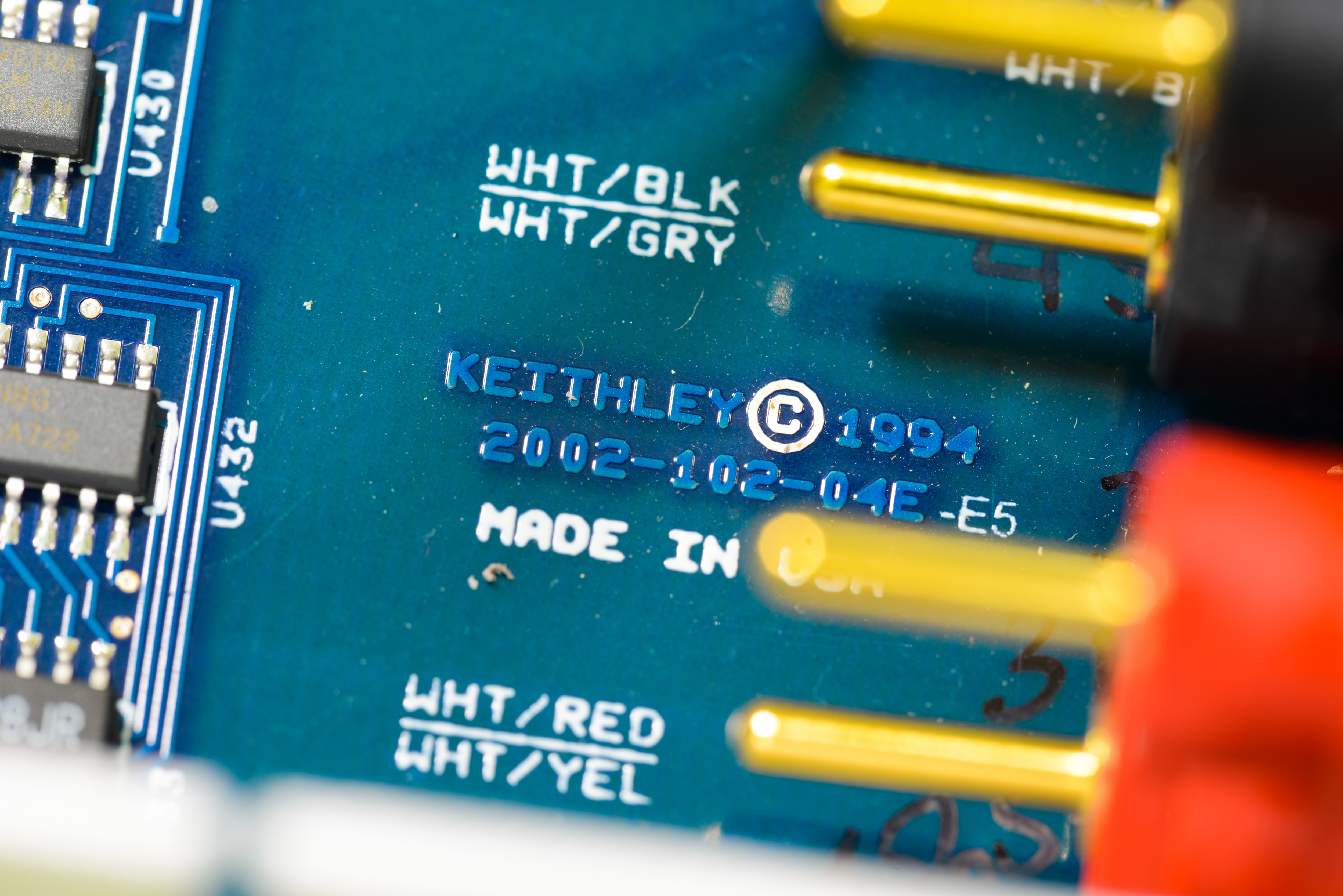
Analog board is labelled 2002-102-04E-E5, designed in 1994, made in USA :)
Firmware
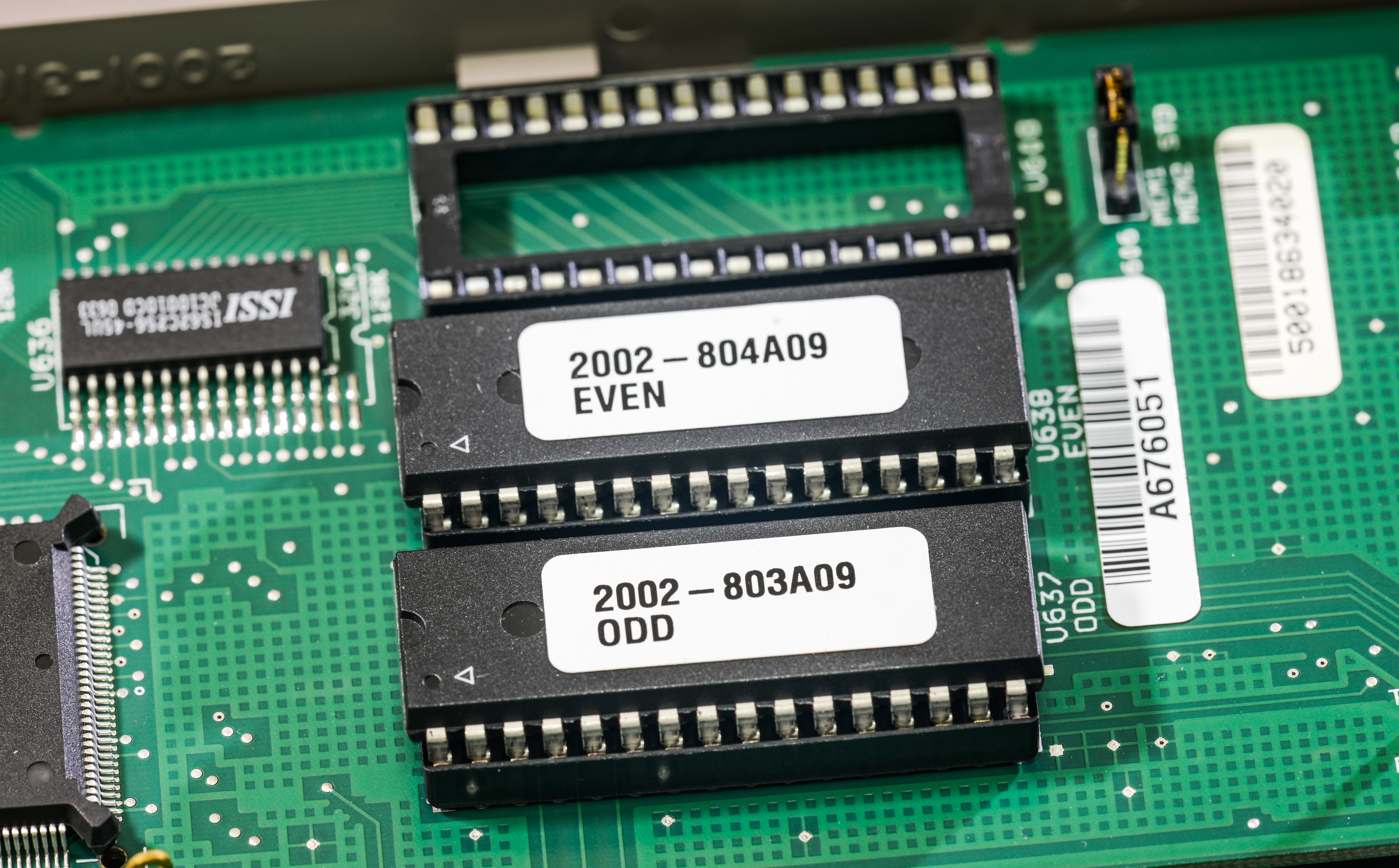
Firmware stored in standard JEDEC-compliant memory ROMs which can be UV EPROM or OTP PROMs. Some, but not all, compatible ROM ICs:
- ST 27C4001-15F1
- AMD 27C040 (UV EPROM)
| Firmware version | Combined binary | ODD ROM | EVEN ROM |
|---|---|---|---|
| Model 2002 A05, Ver. 52.1, May 11 10:34:54 EDT 1995 | 2002-A05 | 2002-803-A05 | 2002-804-A05 |
| Model 2002 A06, Ver. 56.1, Feb 26 11:26:54 EST 1996 | 2002-A06 | 2002-803-A06 | 2002-804-A06 |
| Model 2002 A09, Ver. 69.1, Oct 23 09:26:16 EDT 2000 | 2002-A09 | 2002-803-A09 | 2002-804-A09 |
| Model 2002 A10, Ver. 74.1, Jun 10 14:30:55 EDT 2008 | 2002-A10 | 2002-803-A10 | 2002-804-A10 |
Based on binary comparison, firmware version A09 added support for Type N thermocouples and SPRTD which was absent in A06, at least based on text strings difference. Also there is new extra strings – HPR.HPRECISION, ISN, A4, B4, A7, B7, C7, RZERO, RZER. It seems that A06 have also only 9 settings profiles (SAV0 to SAV8), while A09 and later have 10 (SAV0 to SAV9).
HPR string is related to GPIB readings format, as explained in User’s manual:
:EXPonent <name>
:FORMat:EXPonent <name> Set exponent format.

<name> = NORMal Normal format
         HPRecision High-precision format

:EXPonent? Query exponent format

This command defines the exponent format. The default setting is NORMal, in which case the returned value is formatted according to the engineering units of the present range (for example, 0.0012341E+03 on the 2k, 20k, or 200k range). Choosing HPRecision selects the highest precision possible, so the above example would be returned as 1.2341234E+00 with three extra digits of precision.

Example command:

PRINT #1, "output 16; :form:exp hpr" ' Set high precision.
As for other items, User’s manual also list them:
:RZERo <NRf>

[:SENSe[1]]:TEMPerature:RTD:RZERo <NRf> Specify resistance at 0°C

<NRf> = 0 to 10000 Specify RTD Resistance at 0°C (in ohms)

:RZERo? Query RTD resistance at 0°C

This command is used to check and/or change the Resistance at 0°C. Keep in mind that changing the current resistance value changes the Type to USER (see :RTD:TYPE).

Example command:

PRINT #1, "output 16; temp:rtd:rzer 200; rzer?" ' Specify RZero value
PRINT #1, "enter 16" ' Get response from 2002
SPRTD (RZERO, A4, B4, A7, B7, C7) settings are explained on page 233-234 as well.
One more person mentioned in A09’s credits: Justin Noble
I do not know what is difference between A09 and A10 version, as there are no public revision logs available.
Combined binary images were merged using simple python tool:
# xDevs.com Firmware combine tool
# https://xdevs.com/review/kei2002/

import os

with open('2002_804_a06_even_0150fa76.bin','rb') as a:
    with open('2002_803_a06_odd_01c9ab74.bin','rb') as b:
        with open('K2002_A06_FULL.bin','wb') as x:
            for cnt in range(0, 1048576):
                x.write ("%s%s" % (a.read(1),b.read(1) ) )
There are also NVRAM dumps for reference:
| Memory option NVRAM | Dump |
|---|---|
| Option MEM2, DALLAS DS1248Y-150 | Binary, CHK:00D8D1FE |
| Option none, DALLAS DS1243Y | Binary |
| Option MEM2, DALLAS DS1248Y | Binary |
Calibration ROM dumps:
| Calibration ROM | Combined CALROM | Dump U633 | Dump U634 |
|---|---|---|---|
| xDevs.com’s original, Caldate 2007 | Binary | U633 Binary | U634 Binary |
Many other Keithley Instruments firmware dumps are available on xDevs.com documentation site
Article about different MEM options for Keithley 2001/2002 might be useful for those who want maximize memory without paying official service cost.
As usual, now have tracker and documentation project on our redmine project for Keithley 2002.
Anybody welcome to download available stuff or participate in related endavours.
That’s it for now..
Feel free to ask any suggestions, requests what can do/test with this meter. I don’t plan to do official calibration for it (as it’s double price of 2001) at this moment, and it seem to be pretty spot on already, at least it matches both Kei2400 and Kei2001 (which are still
only 3 weeks period from adjustment/cal) closely.
I do plan to work later on recovering schematics of Model 2002 as well, but have to finish 2001’s prior to that.
Few measurement results around LTZ1000 voltage reference covered in video below:
Perhaps some brave engineer with enough time could modify some functions from 2002 into 2001 (such as extended NPLC range, mod for LTZ1000 reference, 8.5 digit native mode), as actually already digital side and many other sections of both meters are same.
If anybody around have Model 2002 too, and can open it and remove analog board cover for internal photos – such work greatly appreciated! I want collect photo of different revisions/years for 2001/2002 series, but not going to buy every single meter out there. Only 2002 photos found online were some old unit (1997 datecode) on bbs.38hot.net.
Obviously not much owners tear down 6K$ MSRP DMM’s, so that’s why…
One of readers, Todd, shared his Keithley 2002 internal photos:


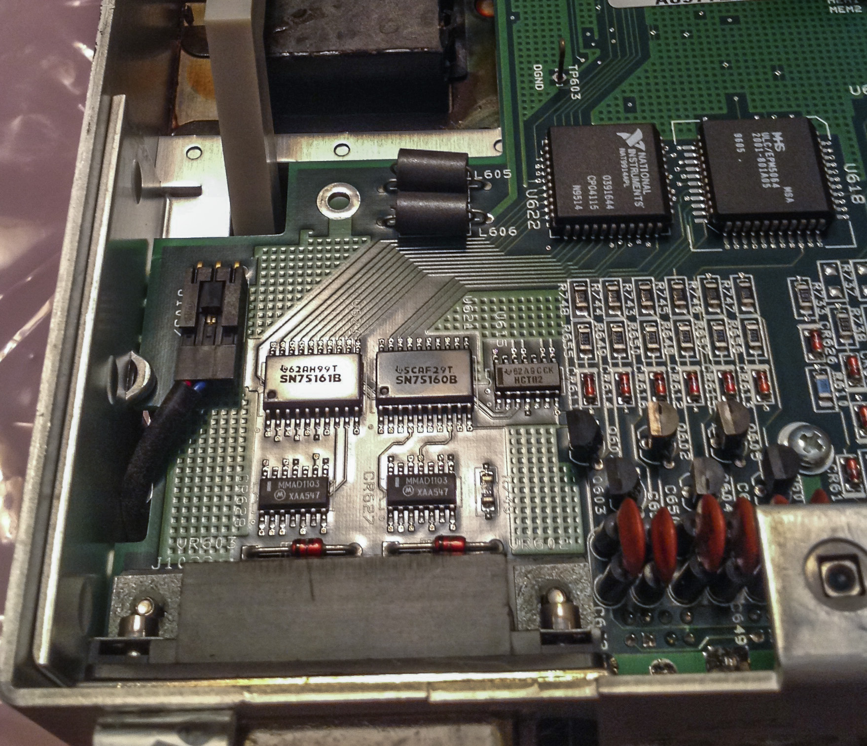
Almost exactly same, except R394 resistor network arrangement, optical isolation devices between boards, and missing CR627,CR628,VR603,VR602 protection diodes at GPIB port on our unit.
NVRAM is DS1248Y, MEM2 optioned, so we can try secret menu to enable extra memory again
Modified: March 1, 2018, 8:02 a.m.
References
- EEVBlog forum : K1801 nanovolt preamp thread
- Secret menu settings in Keithley gear
- Documentation and firmwares
- xDevs.com : HP 3458A 8.5 repair log
- xDevs.com : Experiment to reducing noise of Keithley 2002 ADC
- xDevs.com : Keithley 200x memory options
- xDevs.com : Nanovolt preamp EM10 review
- xDevs.com : Repair of old Keithley 2002