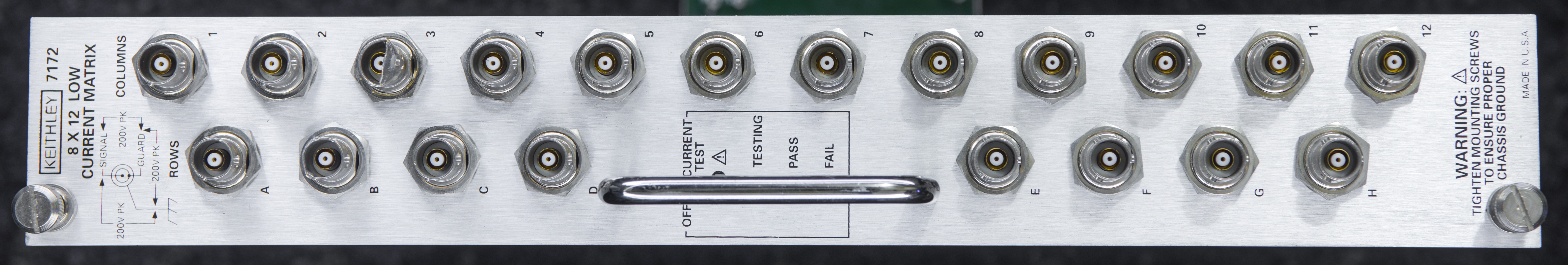
Keithley Model 7172 8 × 12 Low Current Matrix Card
Model 7172 Low Current Matrix Card is designed for semiconductor I-V and C-V measurements. It is configured in an 8 × 12 matrix of two-pole switching with triax 3-lug connectors. An on-board electrometer circuit allows measurement of the offset current and self-test. Today this matrix card is replaced by Model 7174A, which provides similar specifications with lower offset current (10 fA typical) and higher isolation (1014Ω!).
Specifications
| Parameter | Value |
|---|---|
| MATRIX CONFIGURATION | Single 8 rows × 12 columns. |
| OFFSET CURRENT SELF TEST | An onboard electrometer circuit measures offset current when the rear panel switch is pushed. Fail LEDs indicate offset above 500fA |
| Onboard electrometer output | The onboard SMB connector outputs voltage proportional to current (1mV/10fA) |
| CROSSPOINT CONFIGURATION | 2-pole Form A (Signal, Guard) |
| CONNECTOR TYPE | 3-lug TRIAX (Signal, Guard, Chassis). |
| MAXIMUM SIGNAL LEVEL | Pin to pin or pin to chassis: 200V. 1A carry/0.5A switched, 10VA. |
| CONTACT LIFE | Cold Switching: 108 closures. At Maximum Signal Level: 105 closures. |
| PATH RESISTANCE (Per Conductor) | <1.0Ω initial, <1.5Ω at end of contact life. |
| CONTACT POTENTIAL | Differential (Signal to Guard): <30µV, Single ended (Guard to Guard or Signal to Signal): <60µV. |
| OFFSET CURRENT | <500fA, 150fA typical. |
| ISOLATION | Path (Signal to Signal): >1013 Ω, 0.4pF typical. Differential (Signal to Guard): >109 Ω, 170pF typical. Common (Signal and Guard to Chassis): >109Ω, 430pF typical. |
| CROSSTALK (1MHz, 50Ω Load) | <-70dB. |
| INSERTION LOSS (1MHz, 50Ω Load) | 0.22dB typical. |
| 3dB BANDWIDTH (50Ω Load, 50Ω Source) | 30MHz typical. |
| RELAY DRIVE CURRENT (Per Crosspoint) | 30mA |
| RELAY SETTLING TIME | <2ms. |
| EMC | Conforms to European Union Directive 89/336/EEC. |
| SAFETY | Conforms to European Union Directive 73/23/EEC (meets EN61010-1/IEC 1010). |
| ENVIRONMENT | Offset Current and Path Isolation Specifications: 23°C, <50% R.H, Operating: 0° to 50°C, up to 35°C at 70% R.H., Storage: -25° to +65°C. |

Manuals
Instruction manual include full operation instructions, schematics, assembly drawing and BOM.
Model 7172 Low Current 8 × 12 Matrix Card, Instruction Manual, Rev.C, 1991
Model 7172 Instruction Manual Addendum, Rev.B, 1996
Model 7172 Specifications, Rev.B
Firmware
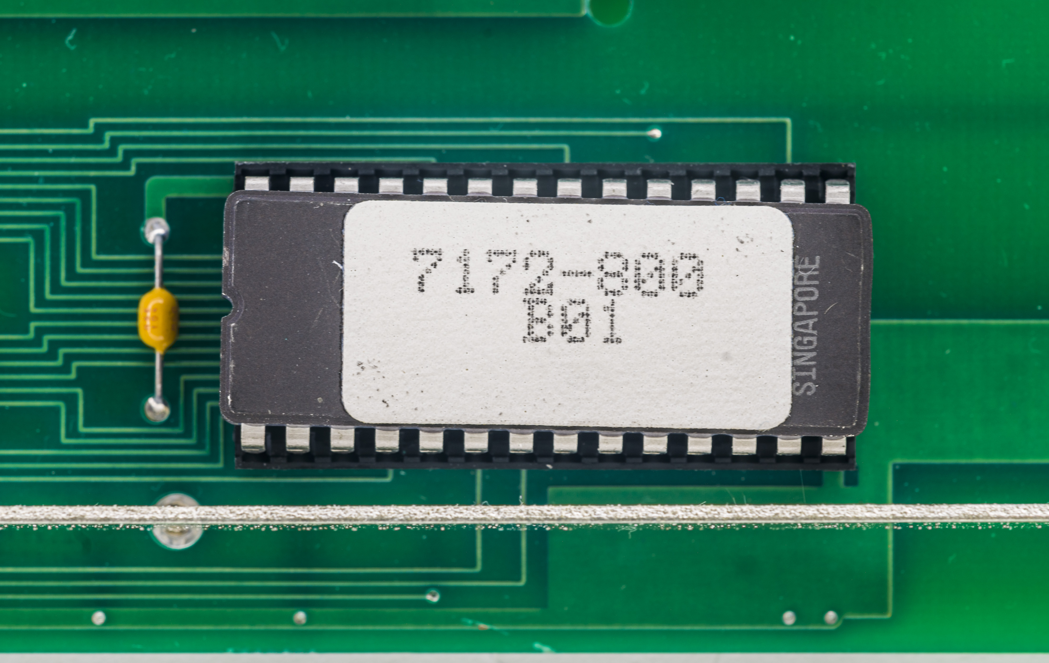
ST M2764P DIP28 ROM binary dump 7172-800-B01.
Review and teardown
This matrix card is designed for use in high-end mainframes, such as Model 707 (6-slot unit) and 708 (1 slot unit) semiconductor switching systems. This module is not compatible with Model 7001 or 7002.
It’s enough to take a look on both 7001 and 7172 sizes to get that straight and clear.
Brief look at block diagram of the matrix board:

It’s fairly simple interface to convert serial control data into parallel I/O to drive lot of relay drivers, with some fail-safe logic and ID ROM. There is no relay actuation counts, so there is no easy way to tell how hard relays were being used in this module.
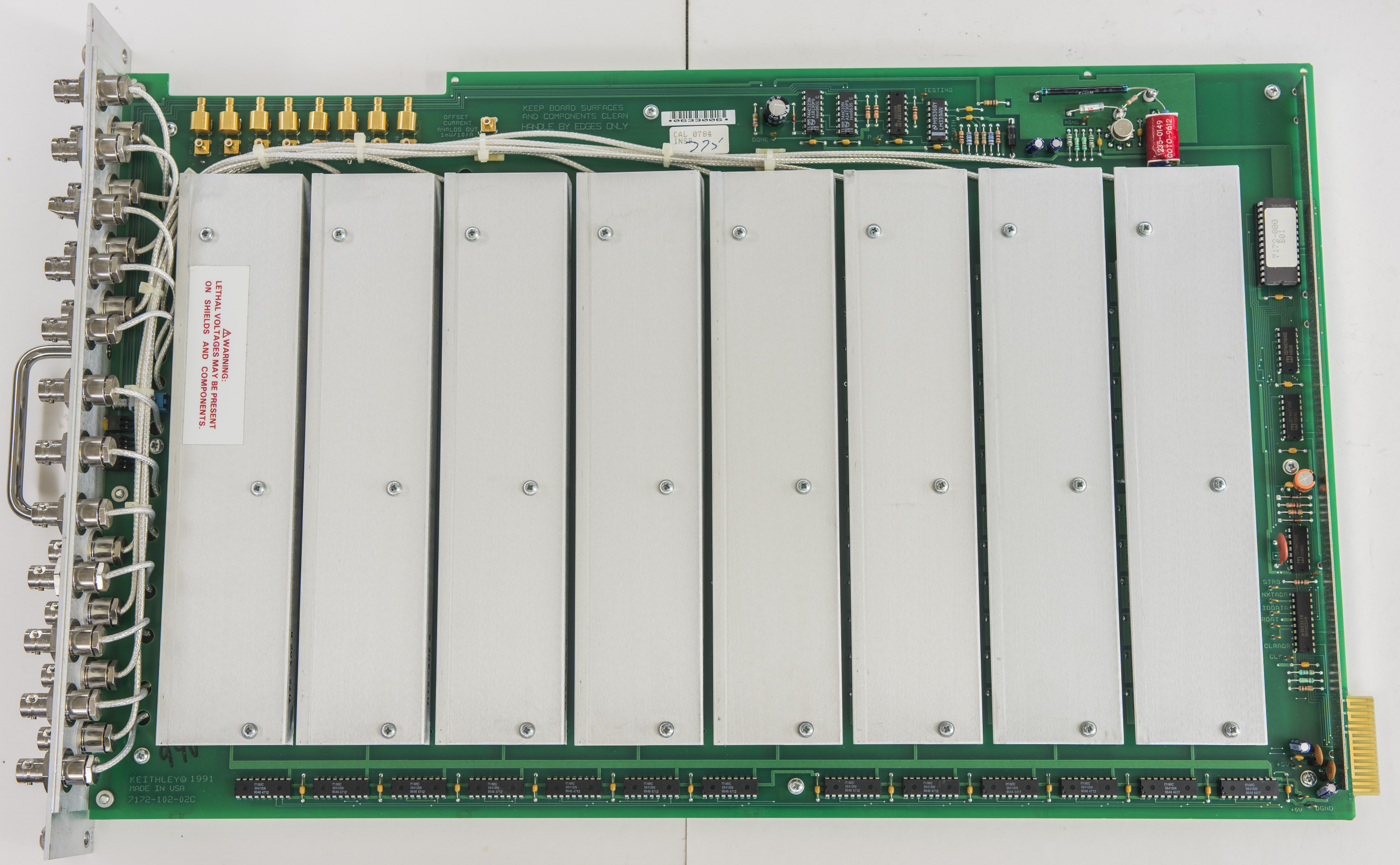
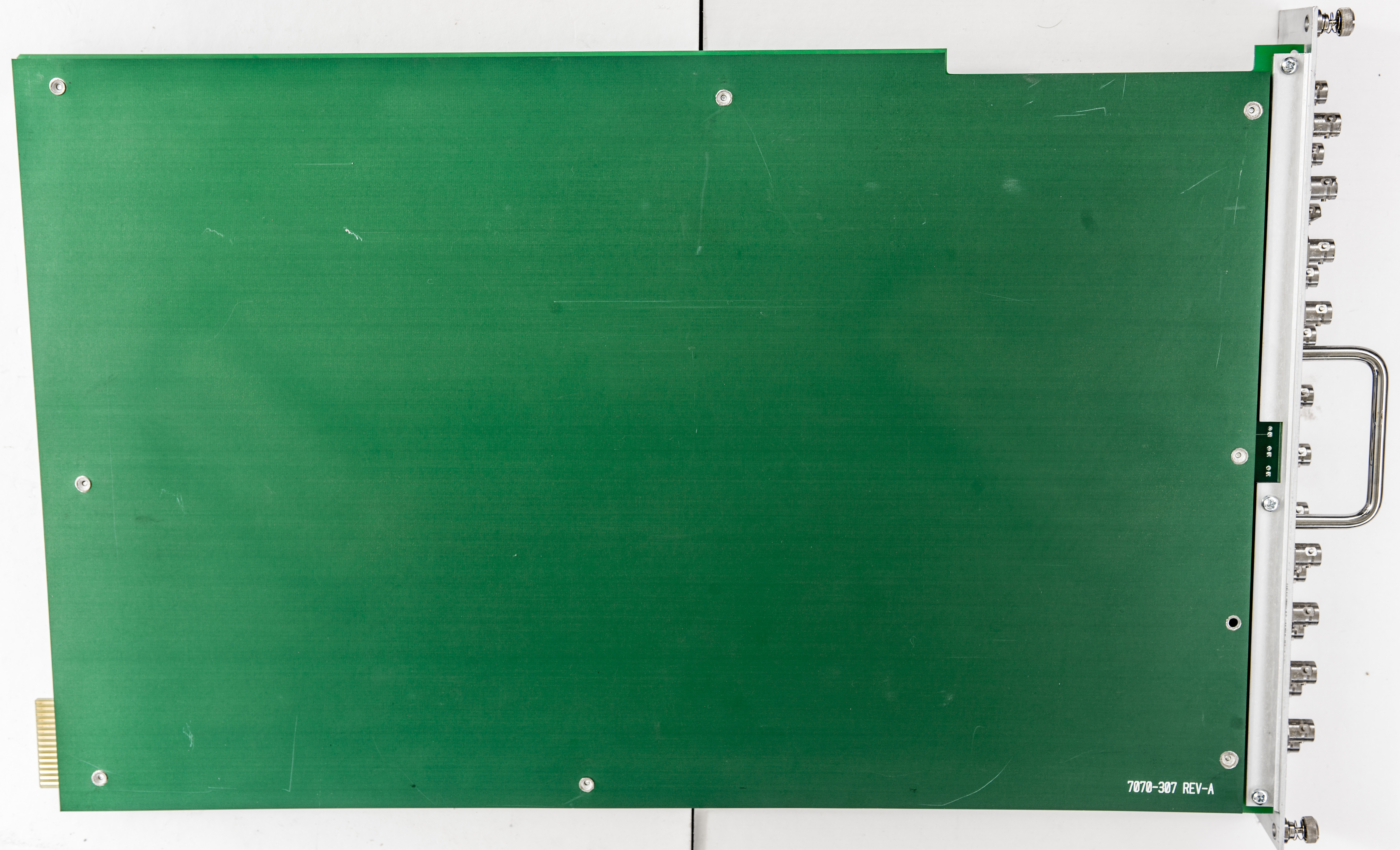
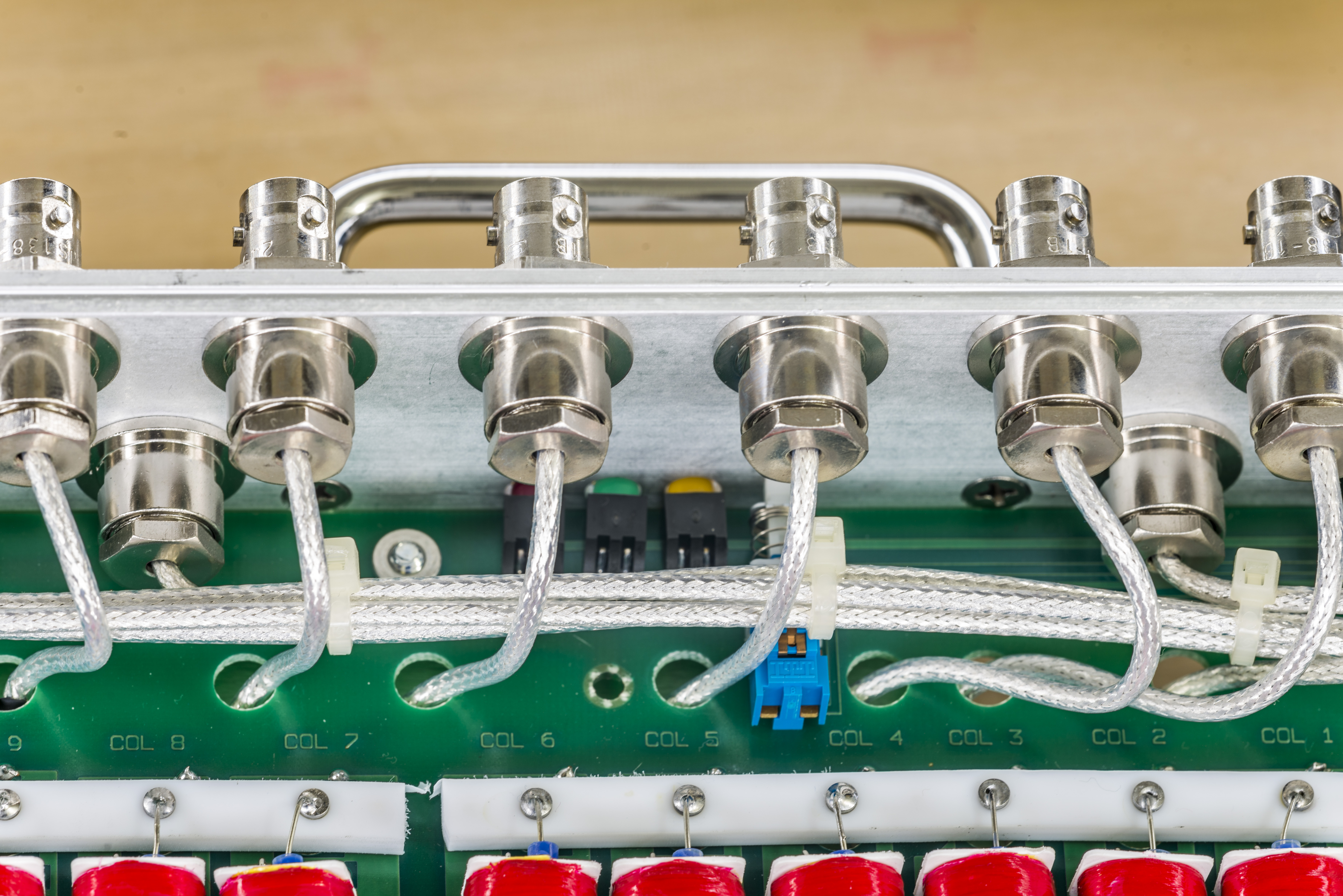
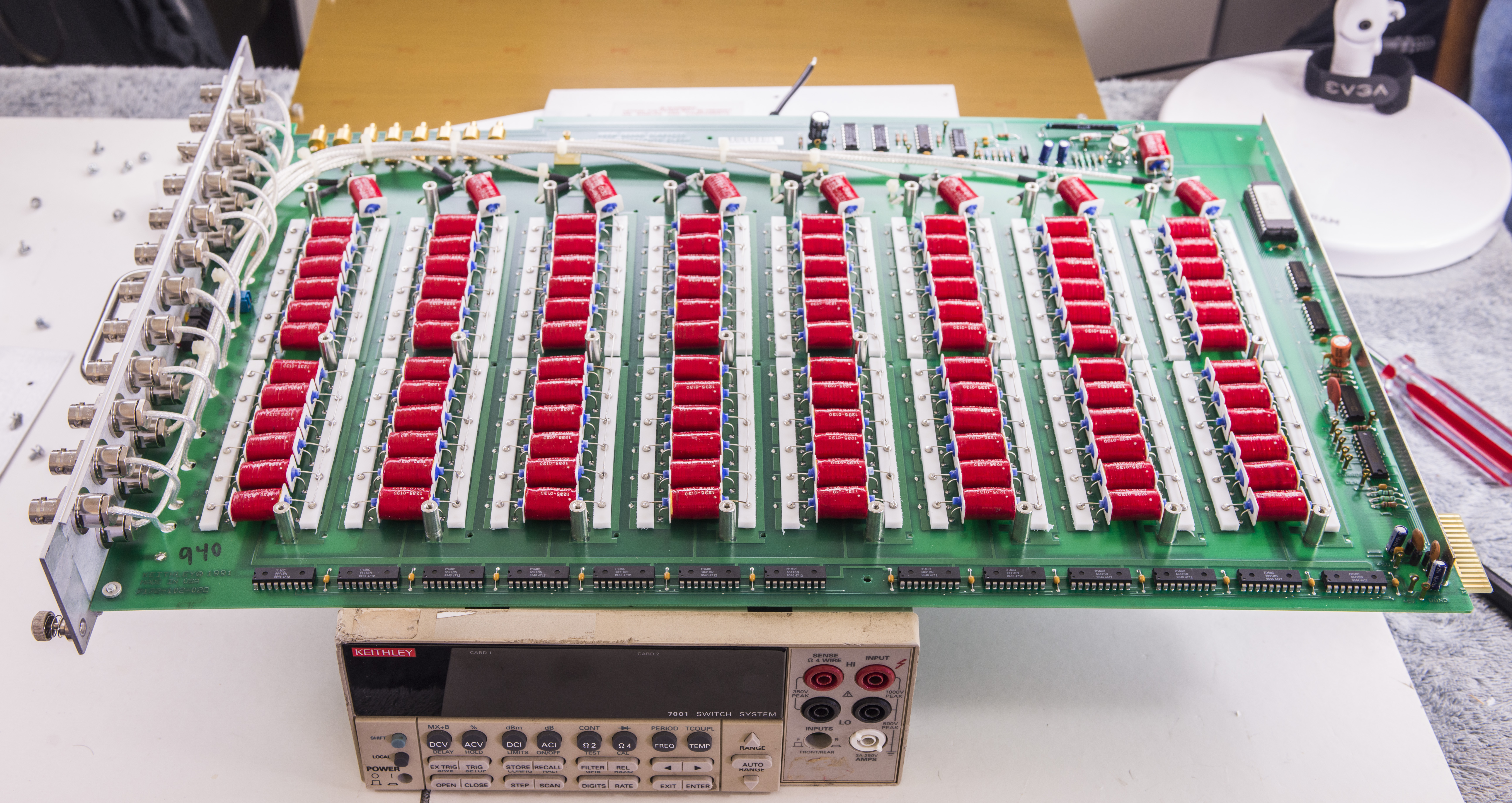
Huge sized card have all components on single PCB, with single-layer bottom shield attached for protection of sensitive nodes. Not much can be seen due to individual aluminum shields on every row.
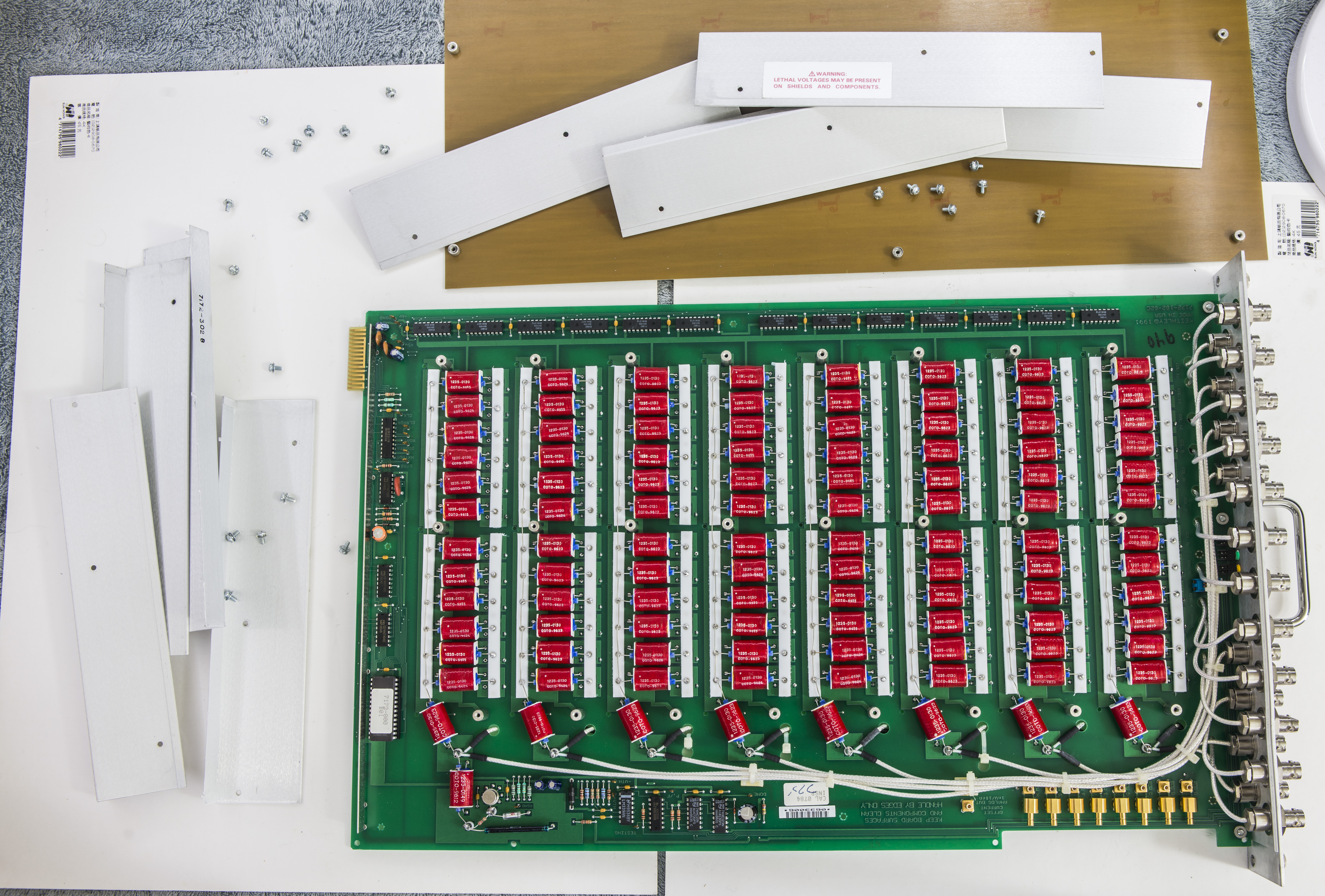
Let’s carefully remove shields:


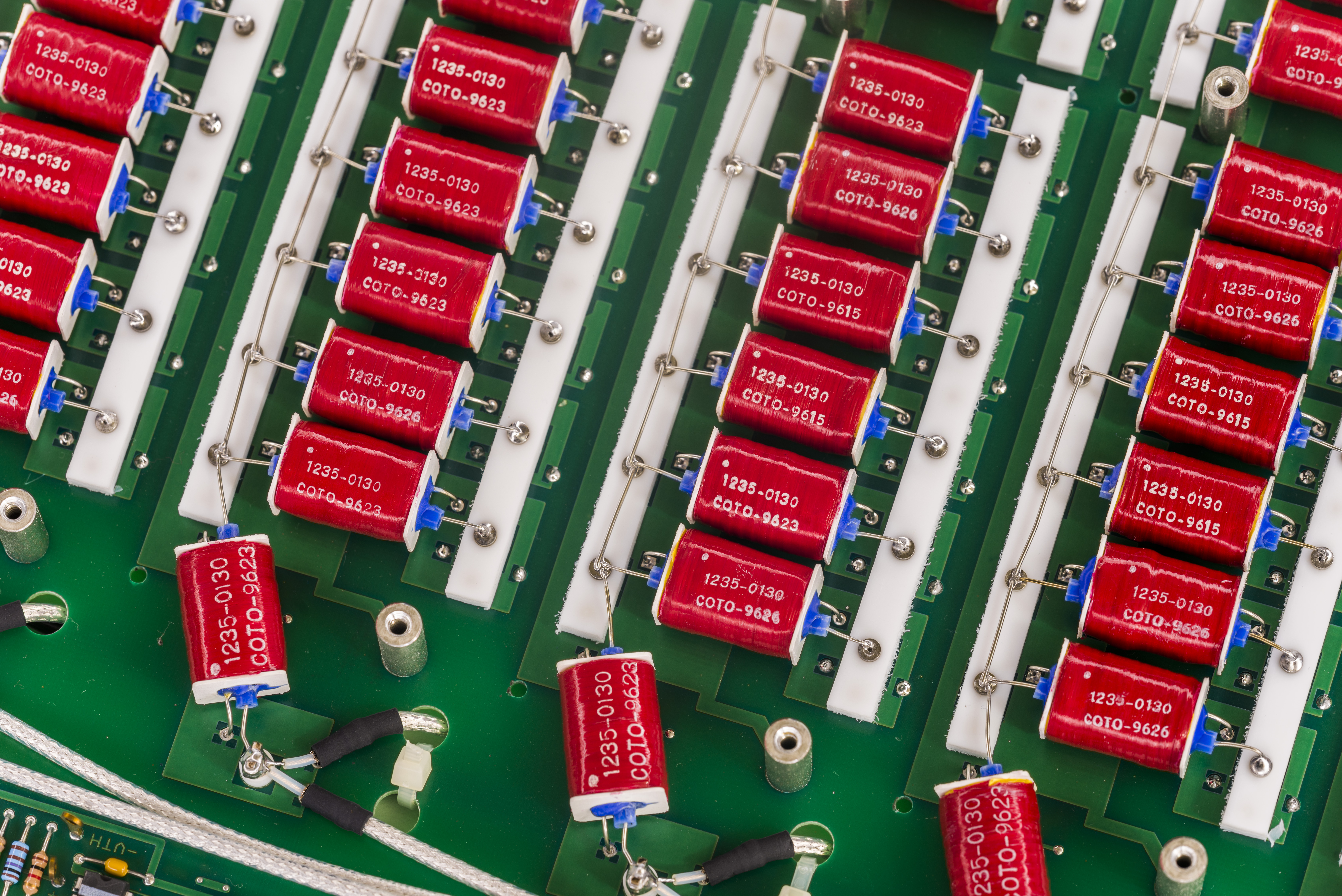
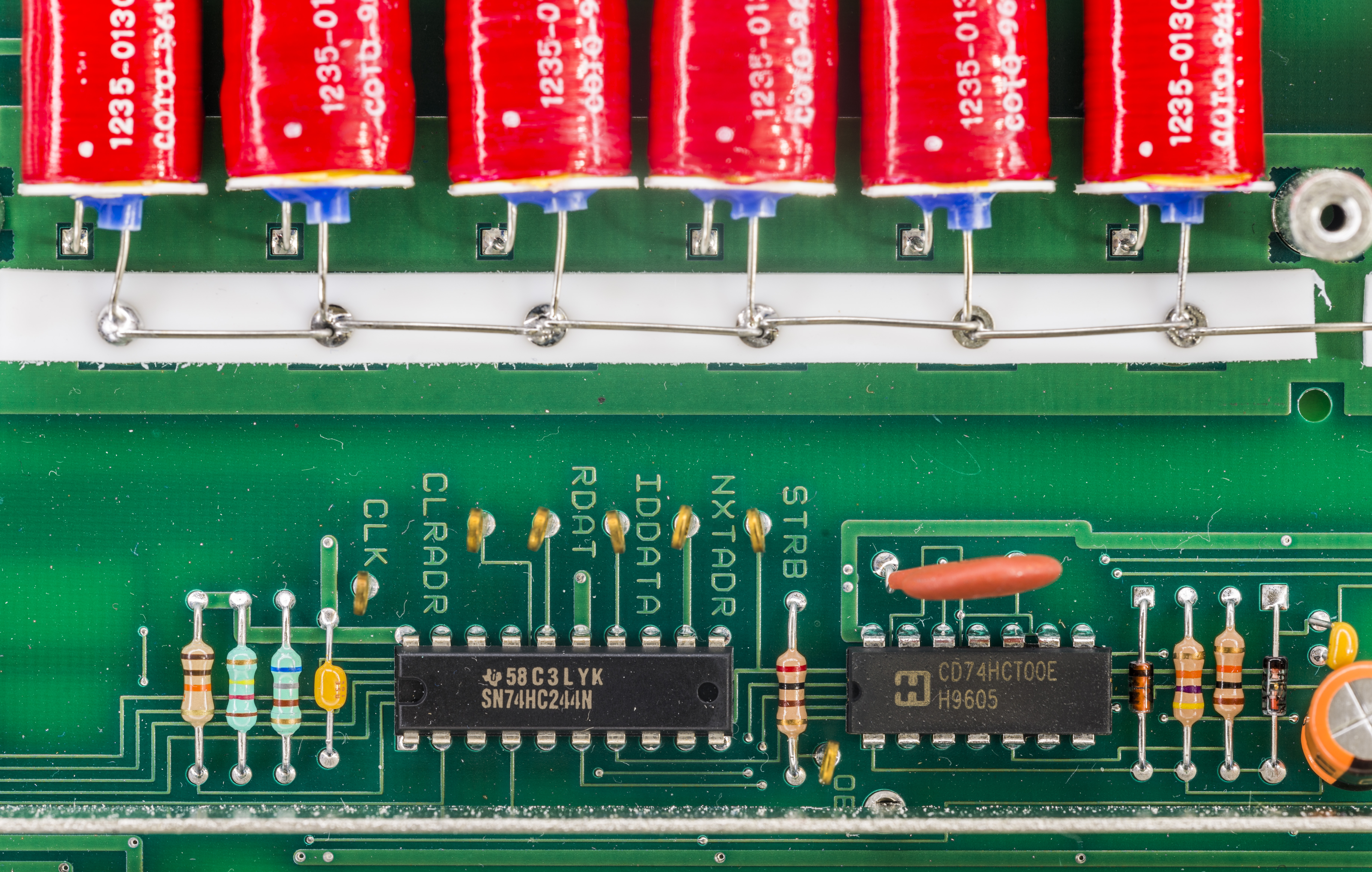
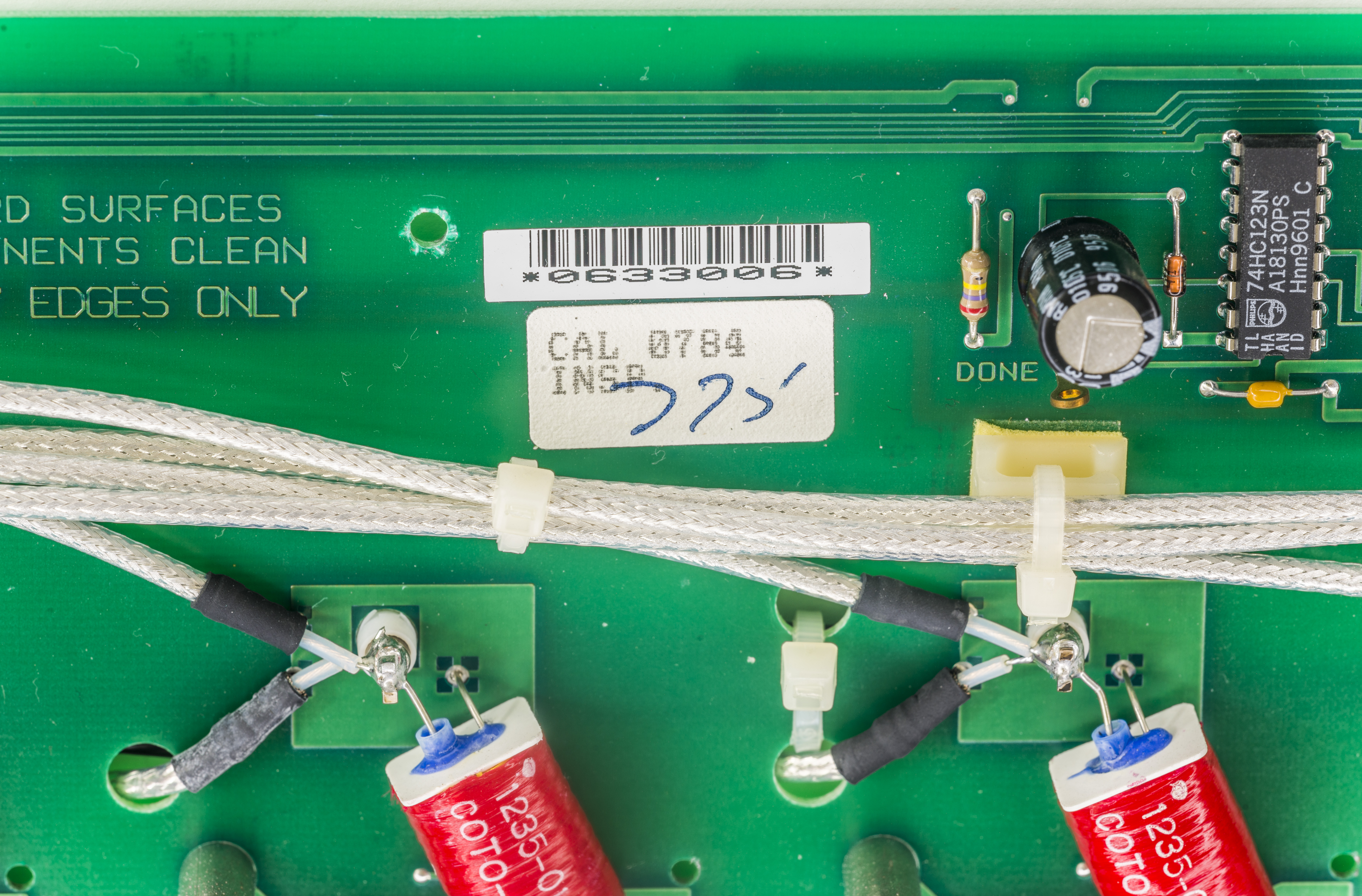
All those vivid red COTO reed relays of 1235-0130 type are just gorgeous.
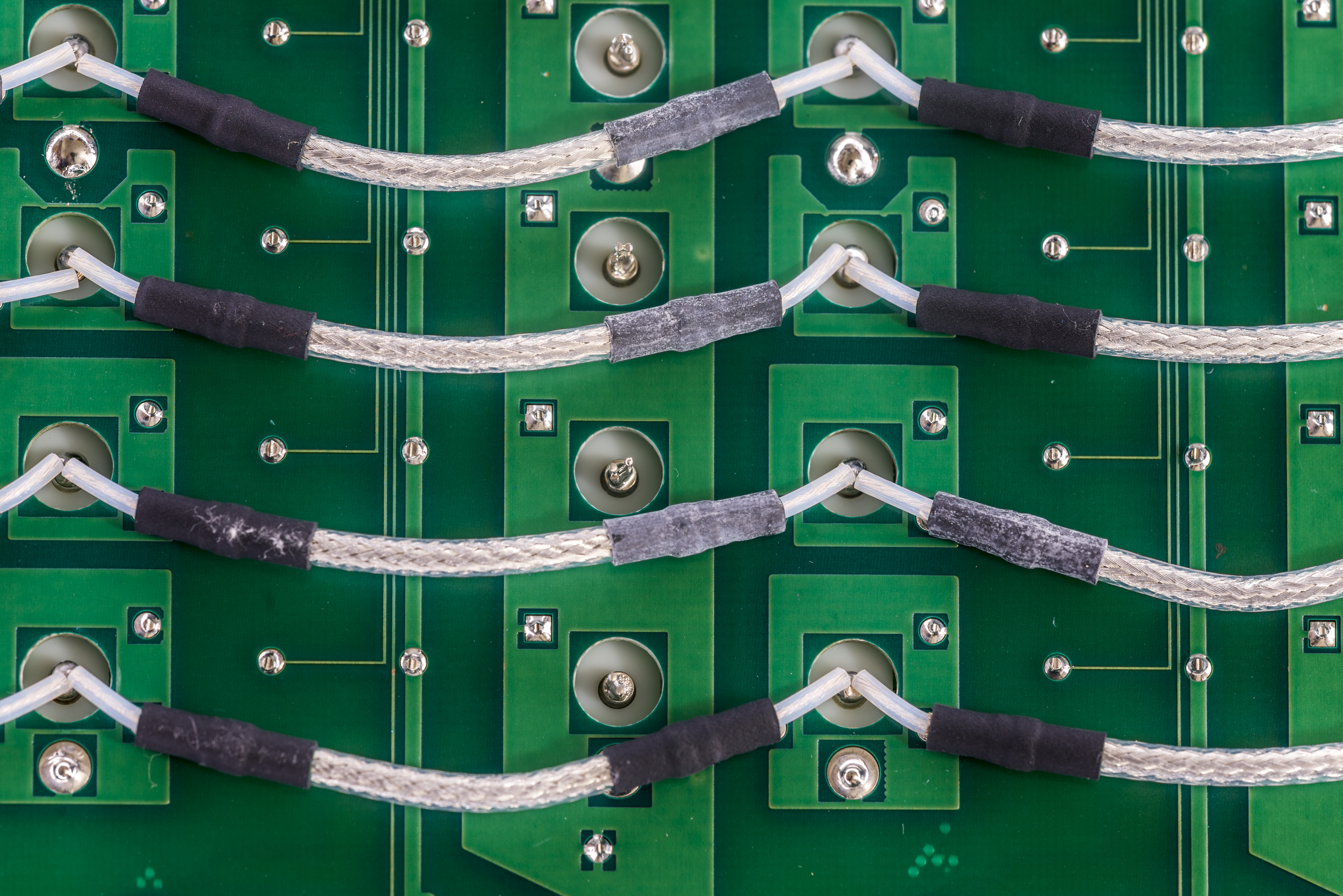
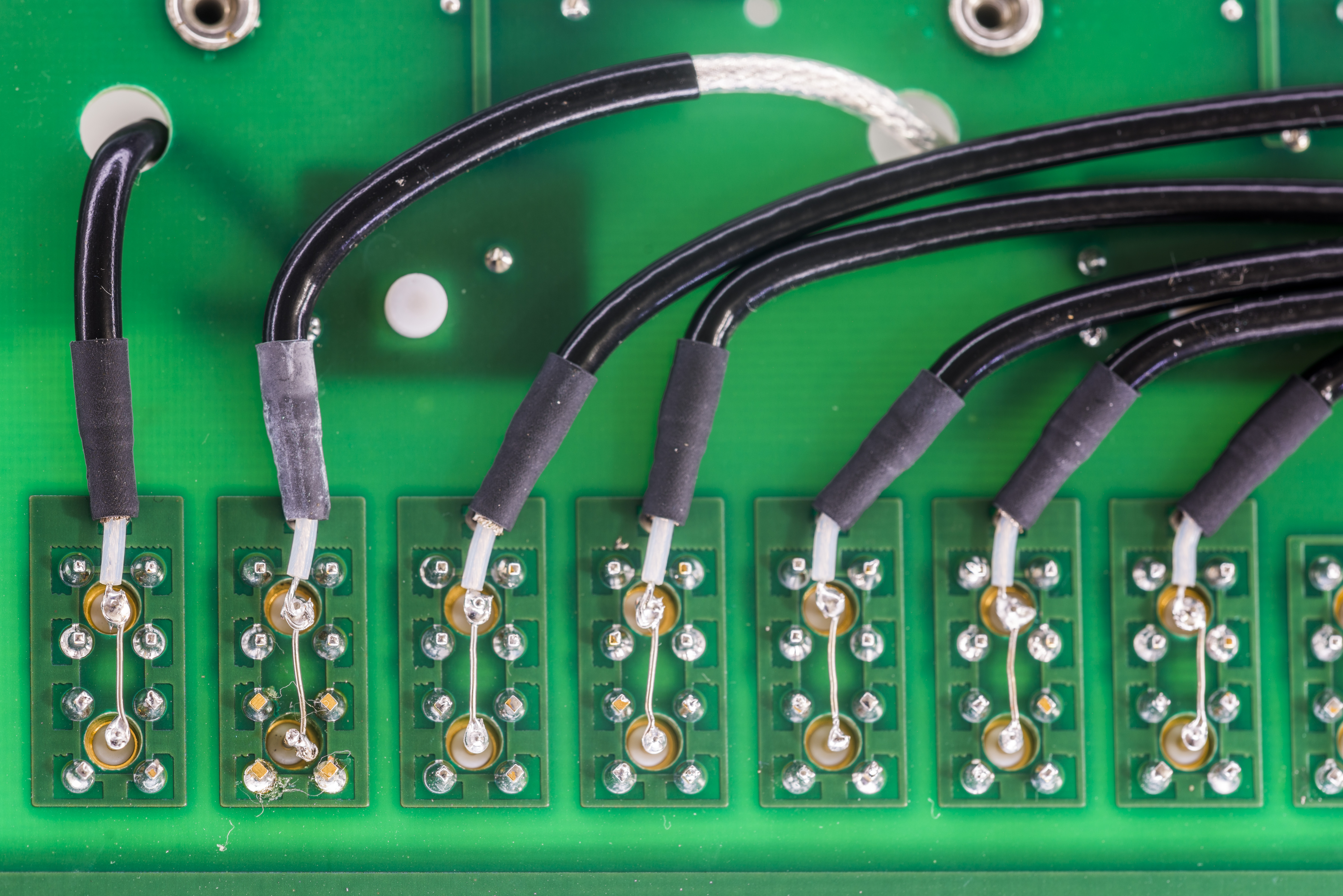
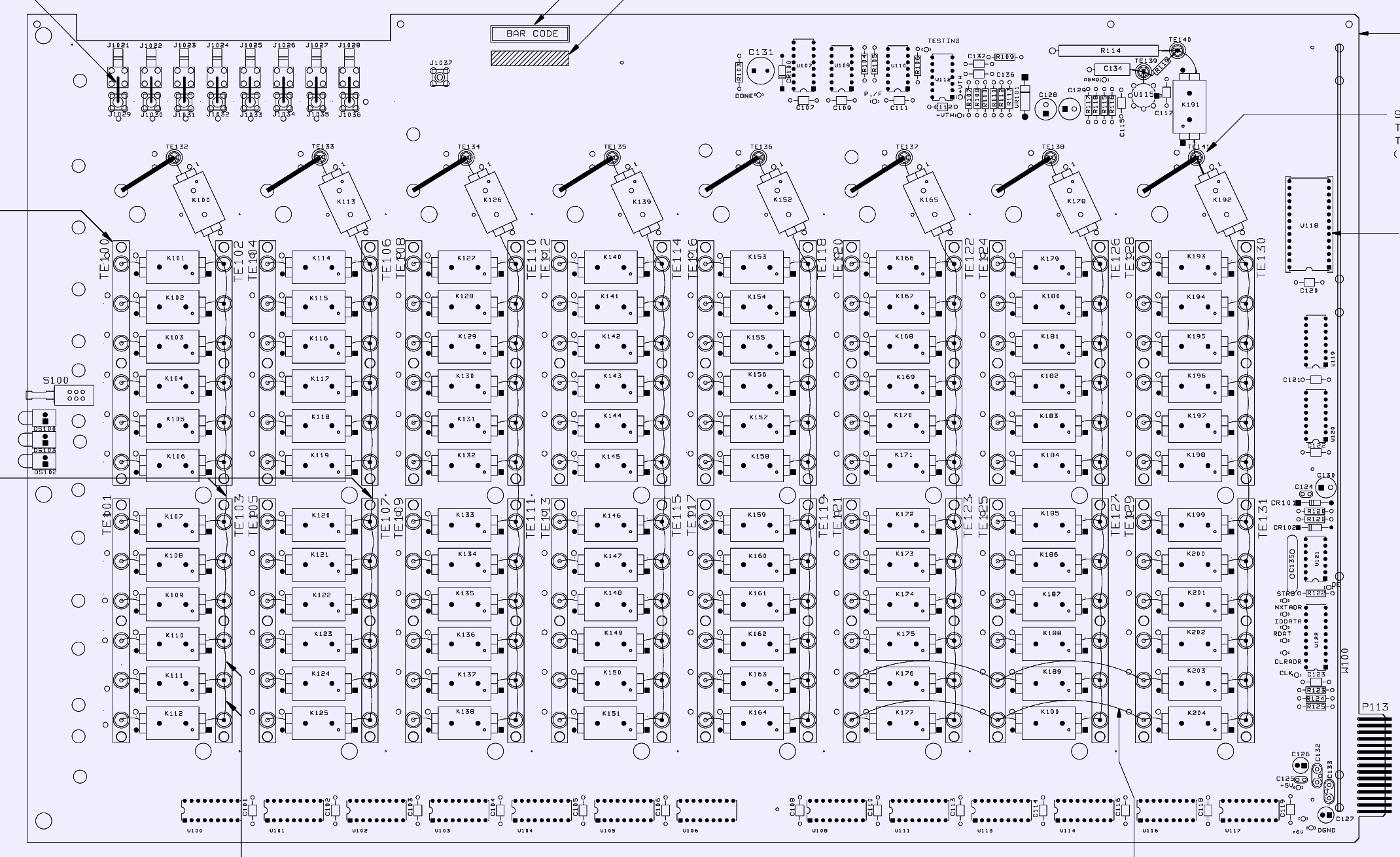
All signal nodes are wired on teflon standoffs to prevent leakage from PCB surface. All wiring connections are routed using teflon-insulated coaxial wire, with shield braid connected to low-impedance guard. Schematic part below shows column connections example:


Here are connections to each reed relay on column at bottom side of the board:
Digital control logic circuits:
Card can be interconnected with other modules in mainframe by internal SMB ports routed to each ROW.
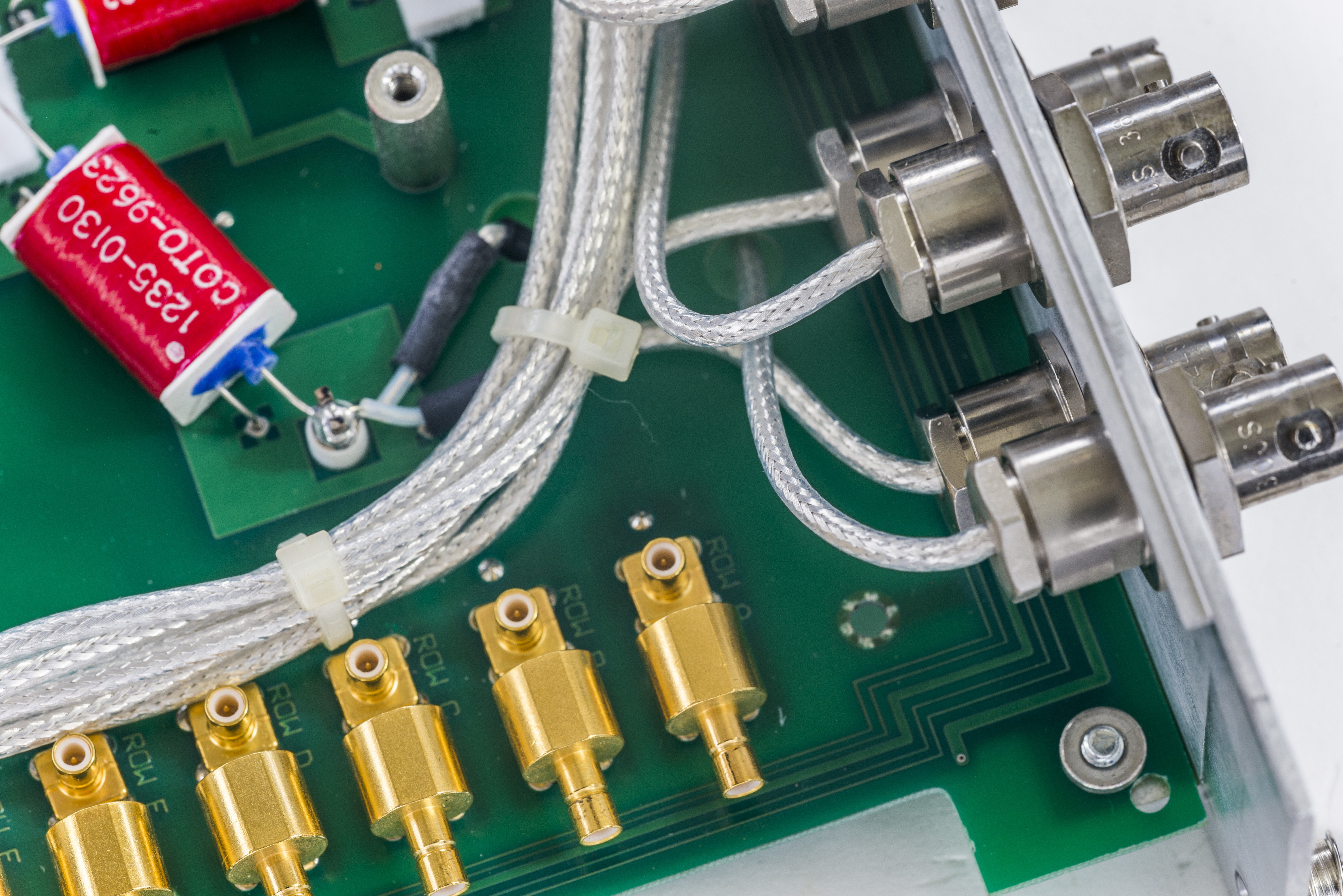
Each row and column routed to one of 20 triaxial panel-mount 3-lug connectors. For these connectors alone this matrix card worth at least 800$USD. Triax connector system is not cheap, most of connectors of this type cost in range of $30-60 USD per piece, but often is one of best solutions for very low current sensitive signal interconnects. It’s a common connector on electrometers and picoamp-level instruments.
To get idea of triax connector internal construction I took damaged connector off and disassembled it:
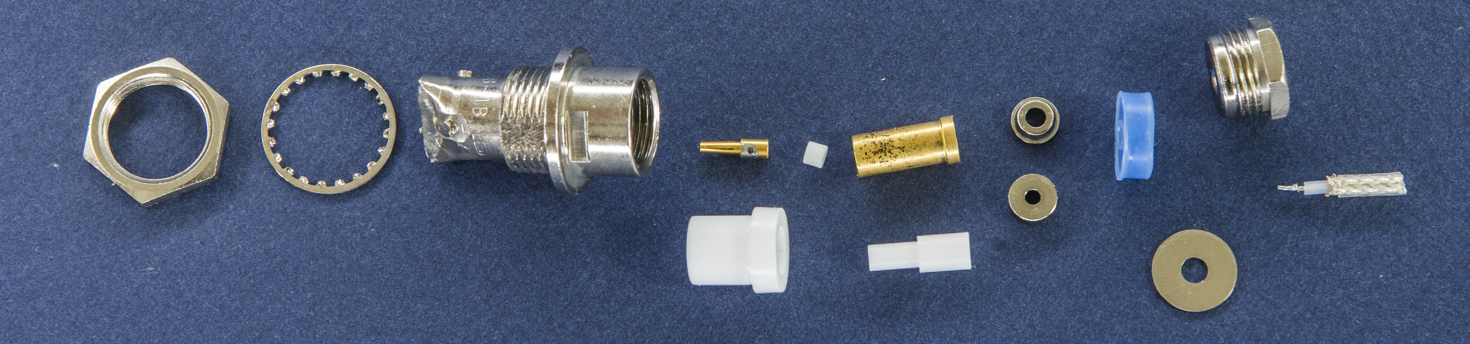
As you can see, it’s much better machining quality compared to generic BNC-type ones, have multiple teflon insulation inserts.
This specific matrix card was sold as broken, and now it’s visible why – column 3 and row B connectors are damaged. But rest are totally fine, so it’s still very useful if there are no other issues.
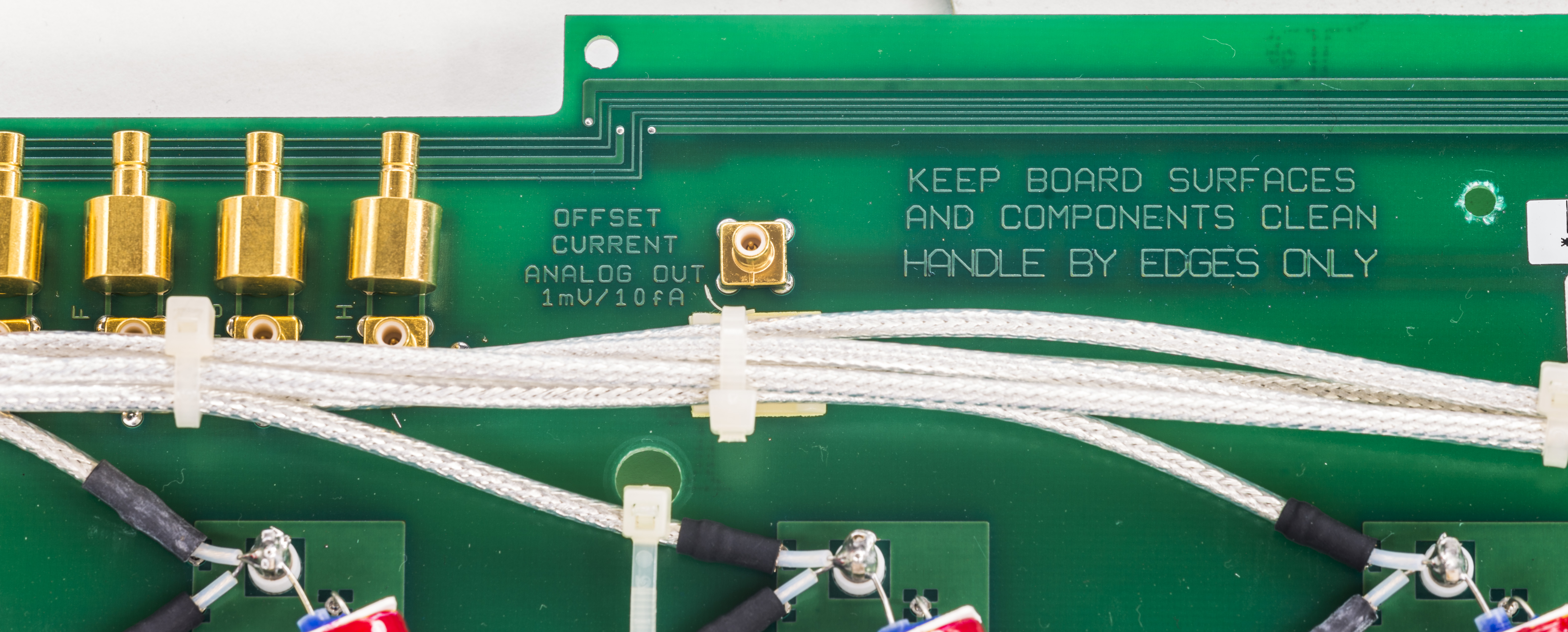
Digital interfacing is rather simple, and connection will be easy, thanks to nice labels of all control signals and voltages directly on PCB.
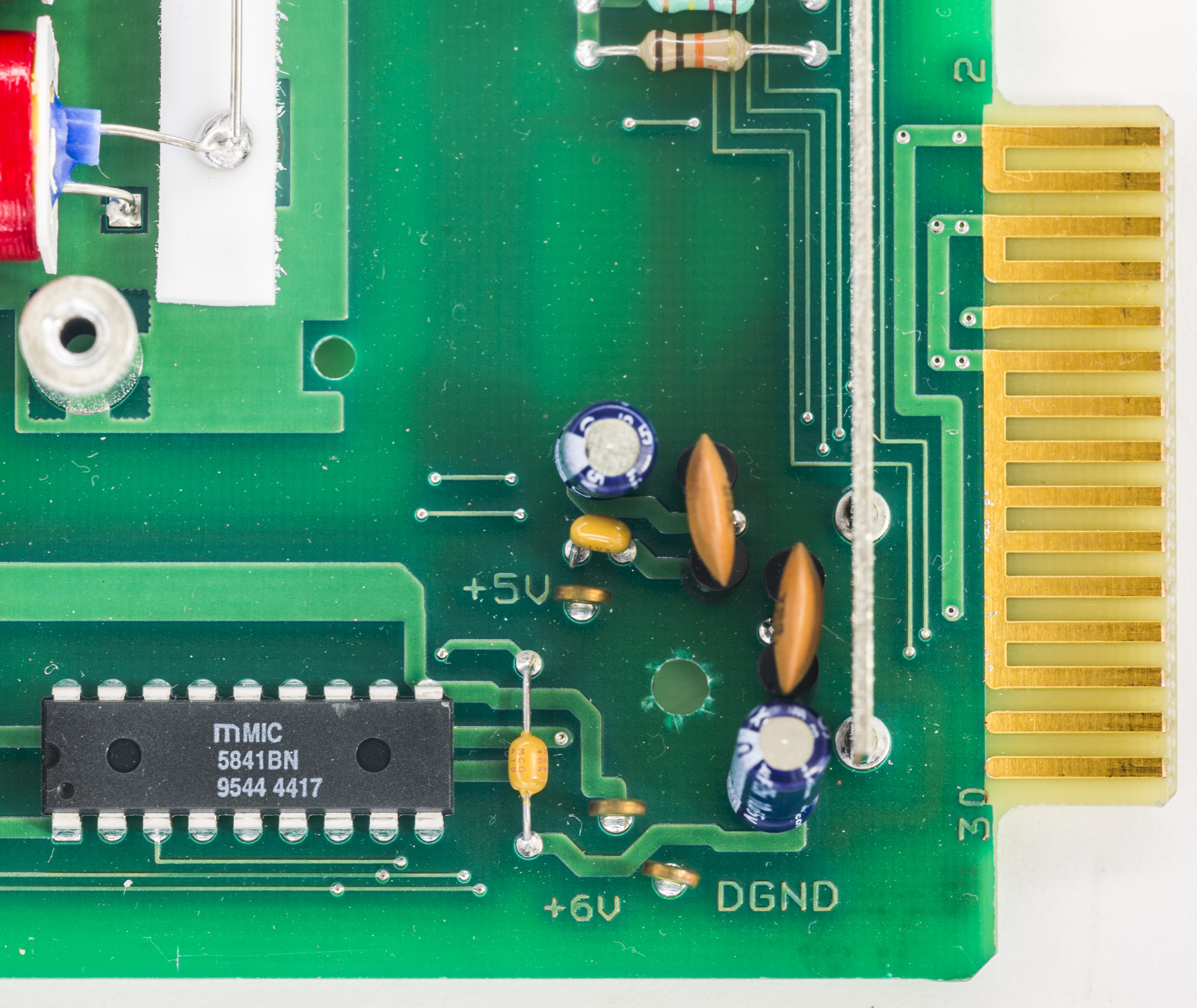
Our card is manufactured in 1996, based on IC’s date codes.
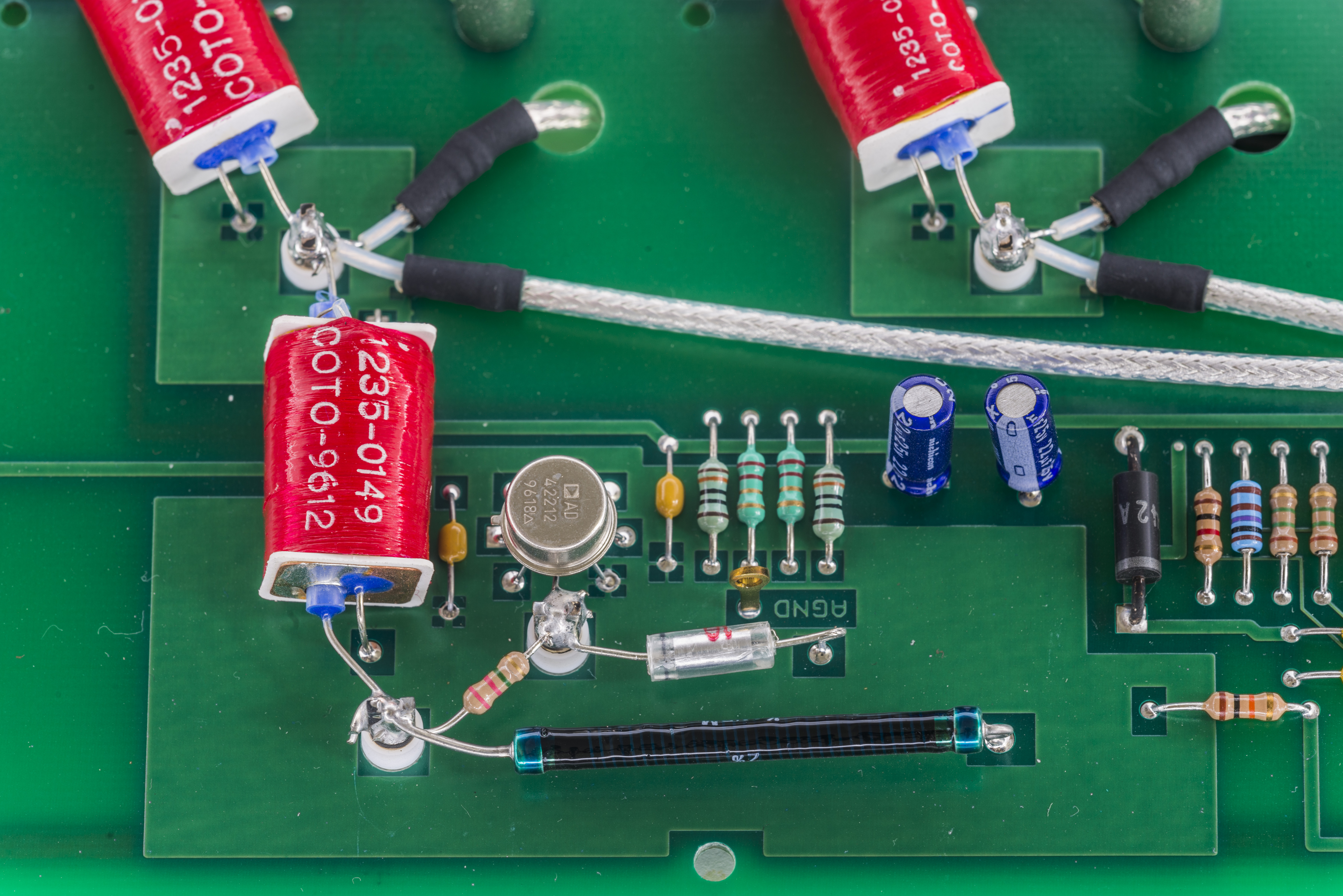
But really special part of Model 7172 is presence of onboard transimpedance amplifier with 100GΩ 2% resistor!

This circuit is used as part of onboard self-test mechanism to measure offset current of row H input, and provide test output with ratio 1mV to each 10fA of leakage current.
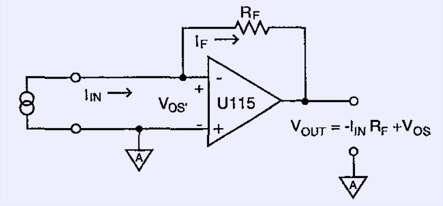
High-value 100GΩ 2% RF resistor and electrometer-grade hermeric metal TO-99 packaged operational amplifier from Analog Devices, AD549L (custom marking AD42212 used for Keithley, we saw this very same part before in Keithley 236 SMU) used to convert this low input current into voltage. This circuit is called transimpedance amplifier. AD549L is specified for 60 femtoamps of maximum input bias current, 0.36 fARMS noise and have common mode input impedance typically 1015 Ω with just 0.8 pF of input capacitance.
It’s rather amazing opamp, even modern ADA4530-1 did not improve these specs much.

Of course all sensitive nodes are lifted above PCB surface using Teflon standoff, be sure. Actual schematics from instruction manual:
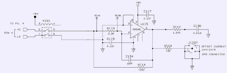
Test voltage available at test SMB connector port.
Overall assembly drawing:
On final note, comparison of Keithley 7172 card with Keithley 7001-sized unit. It’s hard to tell size from photos, so hopefully this will give you a correct scale.

To be continued

Modified: Jan. 9, 2021, 10:11 p.m.