Contents
Introduction
Logic analyzer mainframes and systems like Tektronix TLA704, TLA714, TLA715 and their related modules are very old by modern standards, but not yet obsolete. If engineer need many channels and flexible triggering, often useful for parallel systems debug, there are no much alternatives to real logic analyzers like these TLA700 series. Even though modules which we will review today are back from 2000-2005’s, they still can be handy today for complex system debug. Unlike TLA7AA4 which I use in my own TLA714 these modules use regular 2.54mm pitch headers as input ports, and do not require expensive probes to get started.
There also deeper memory TLA7Q2 and TLA7Q4 modules, which similar to TLA7Nx series but with extended sampling memory to 64M
TLA7M3 module
- 102 Channel Logic Analyzer with up to 2 Mb Depth
- Up to 200 MHz State Acquisition Analysis of Synchronous Digital Circuits
- 2 GHz Deep Timing Analysis with up to 512K Depth per channel
- MagniVu™ Acquisition Technology Provides 2 GHz (500 ps) Timing Resolution to Find Difficult Problems Quickly
- Glitch and Setup/Hold Triggering and Display Finds and Displays Elusive Hardware Problems
- Transitional Storage Extends the Signal Analysis Capture Time
- Full Range of General-purpose and High-density, Non-intrusive Probes
Exterior and interior
Let’s take a look on the module exterior.
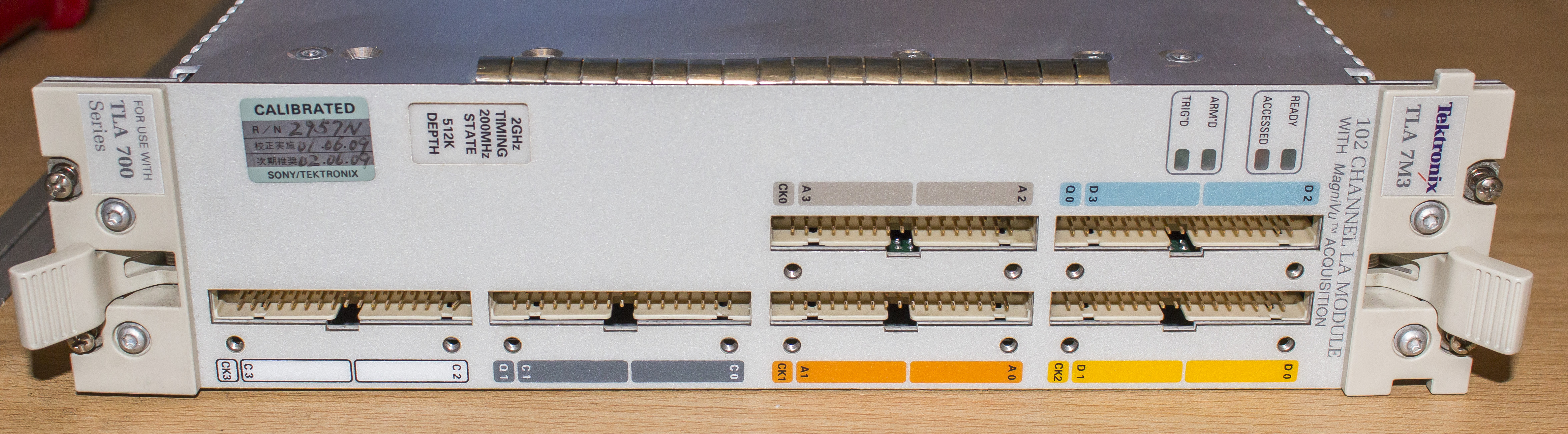
7M3 is 102-channel VXI module for TLA 700 and TLA 7000 series logic analyzer mainframes. Since it’s reduced version with only 102 input channels, there are 6 input connectors, each with 34 pins. There are four LED indicators for various module status reports, and label with speed and depth configuration. Module locks in mainframe with four screws on sides.
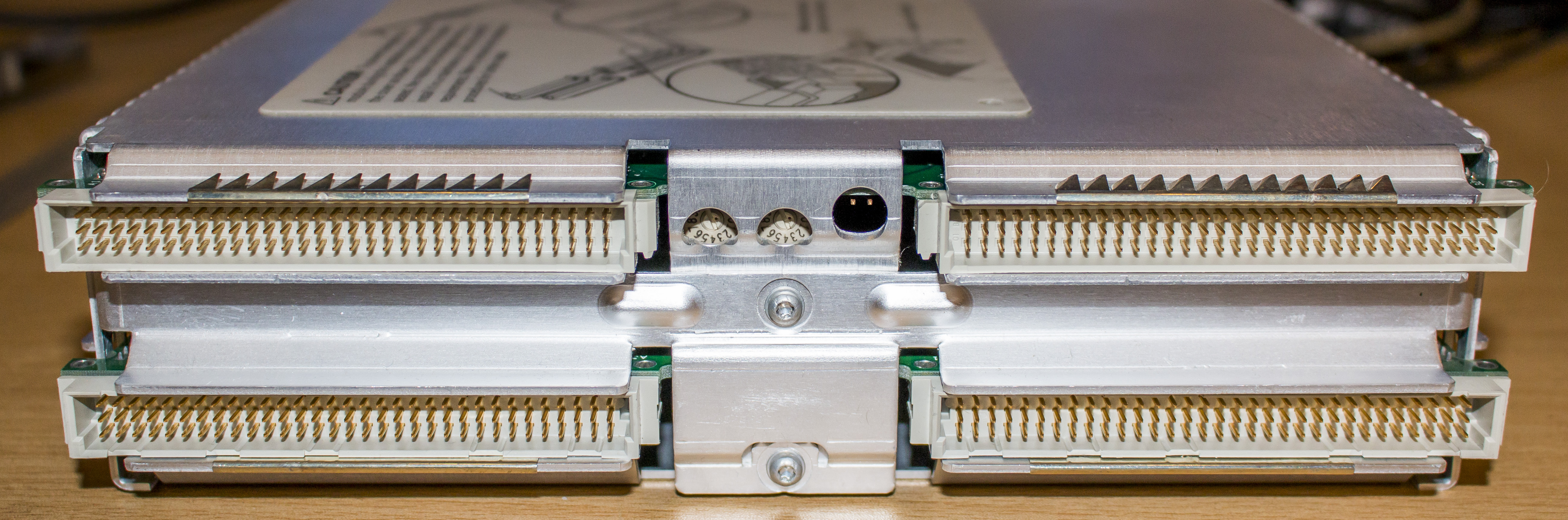
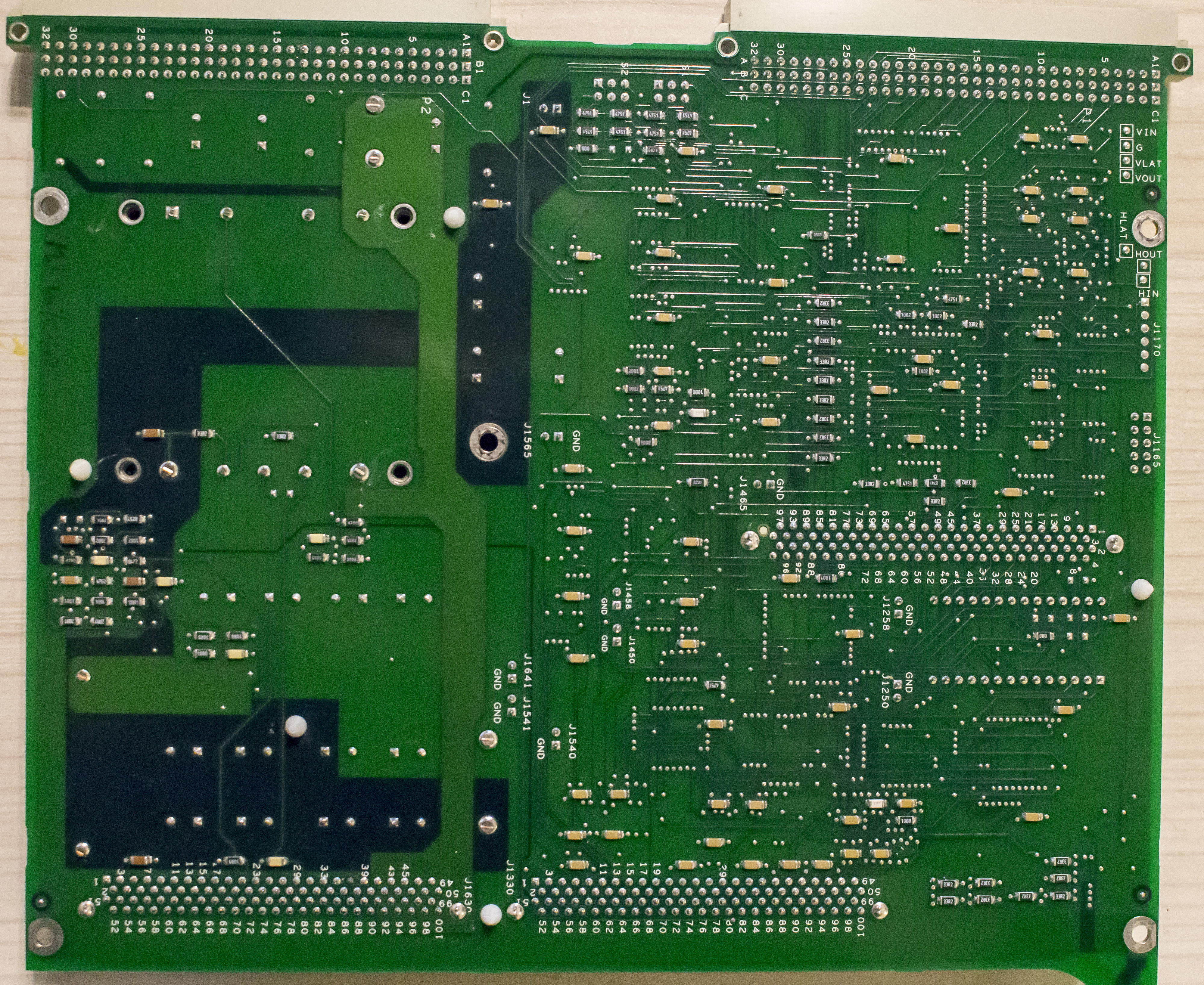
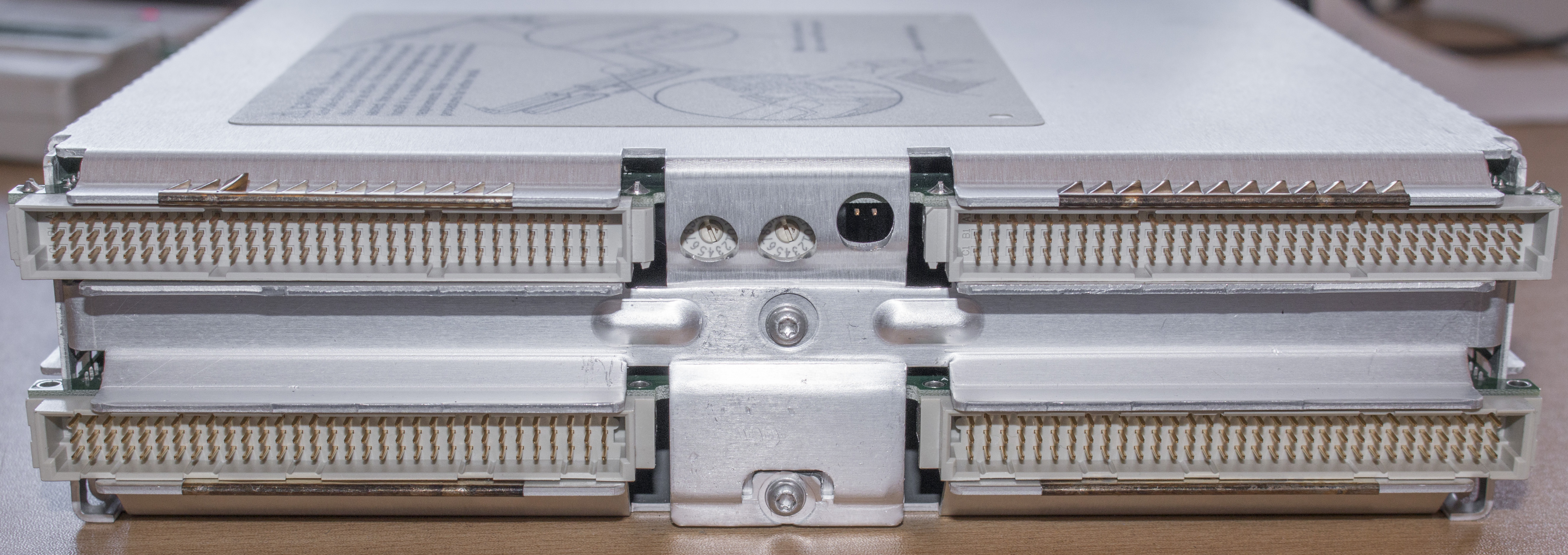
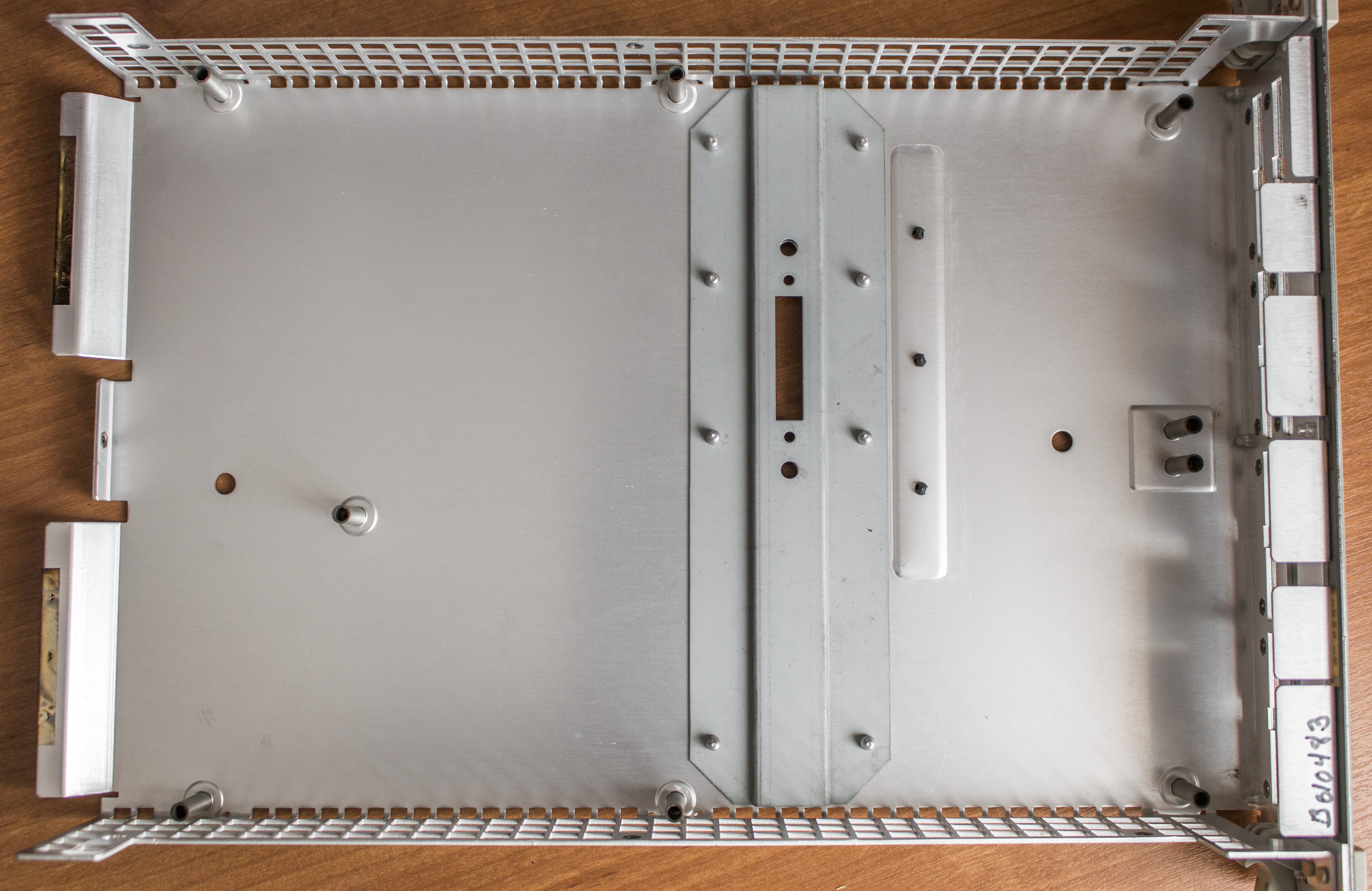
Rear side just have VXI connector ports for interface and power and ID configuration selectors in center.


This module series have only two possible options, with 100MHz state speed and 200MHz. Module here is already 1S with 200MHz state timing speed and 512K samples of depth.
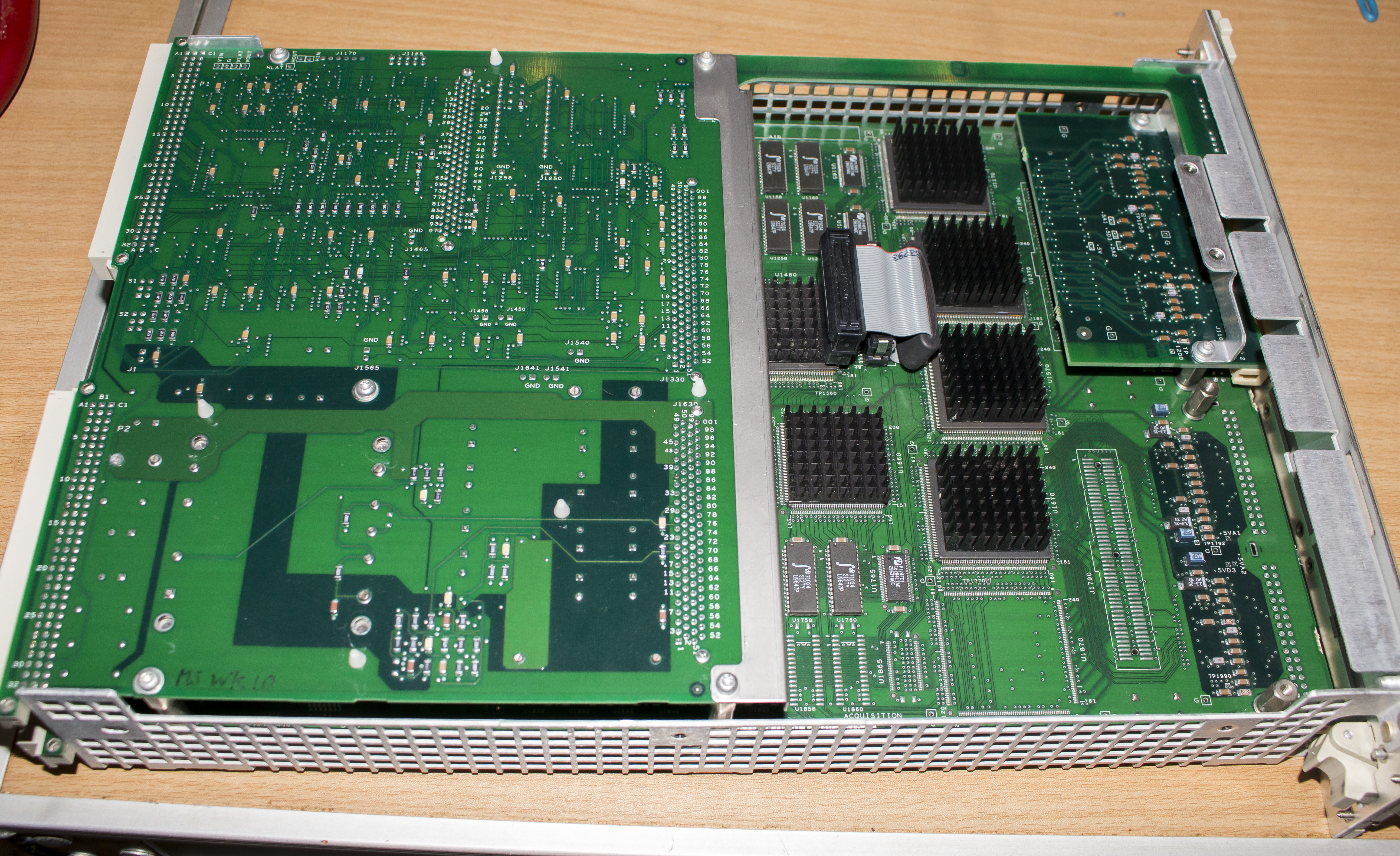
Sandwich of PCBAs inside, with controller on top smaller board and acquisition hardware on bottom bigger board. Take a closer look.
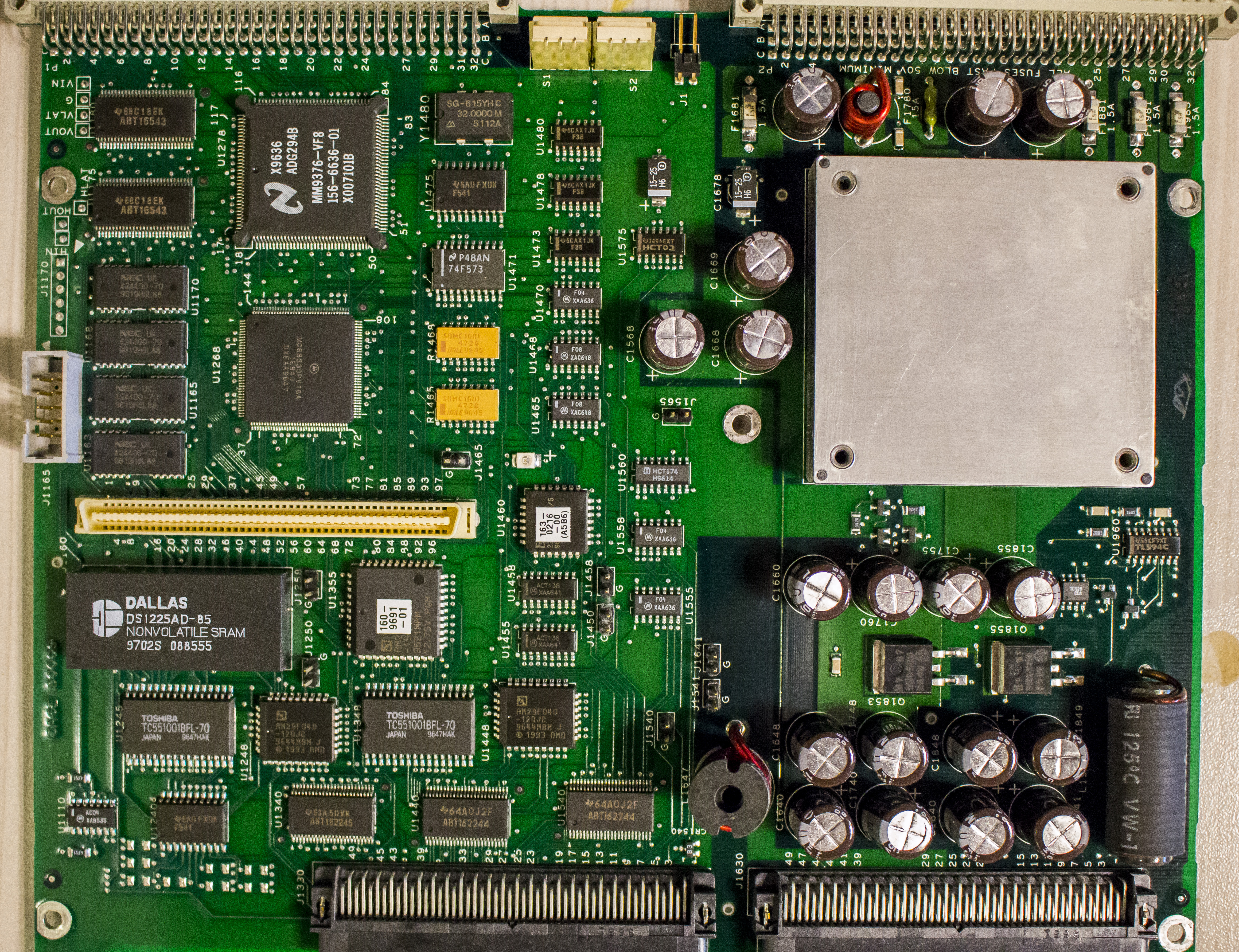
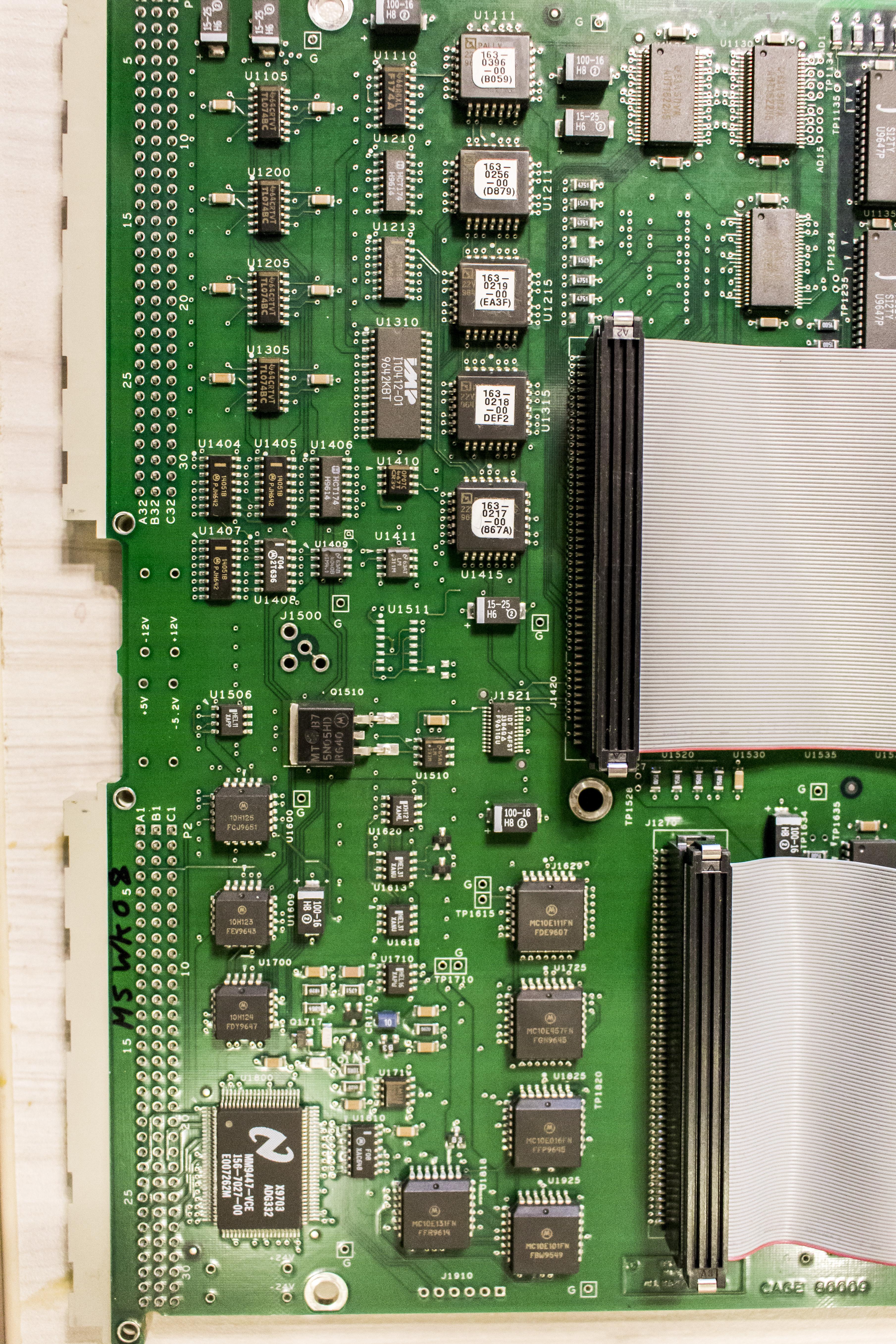
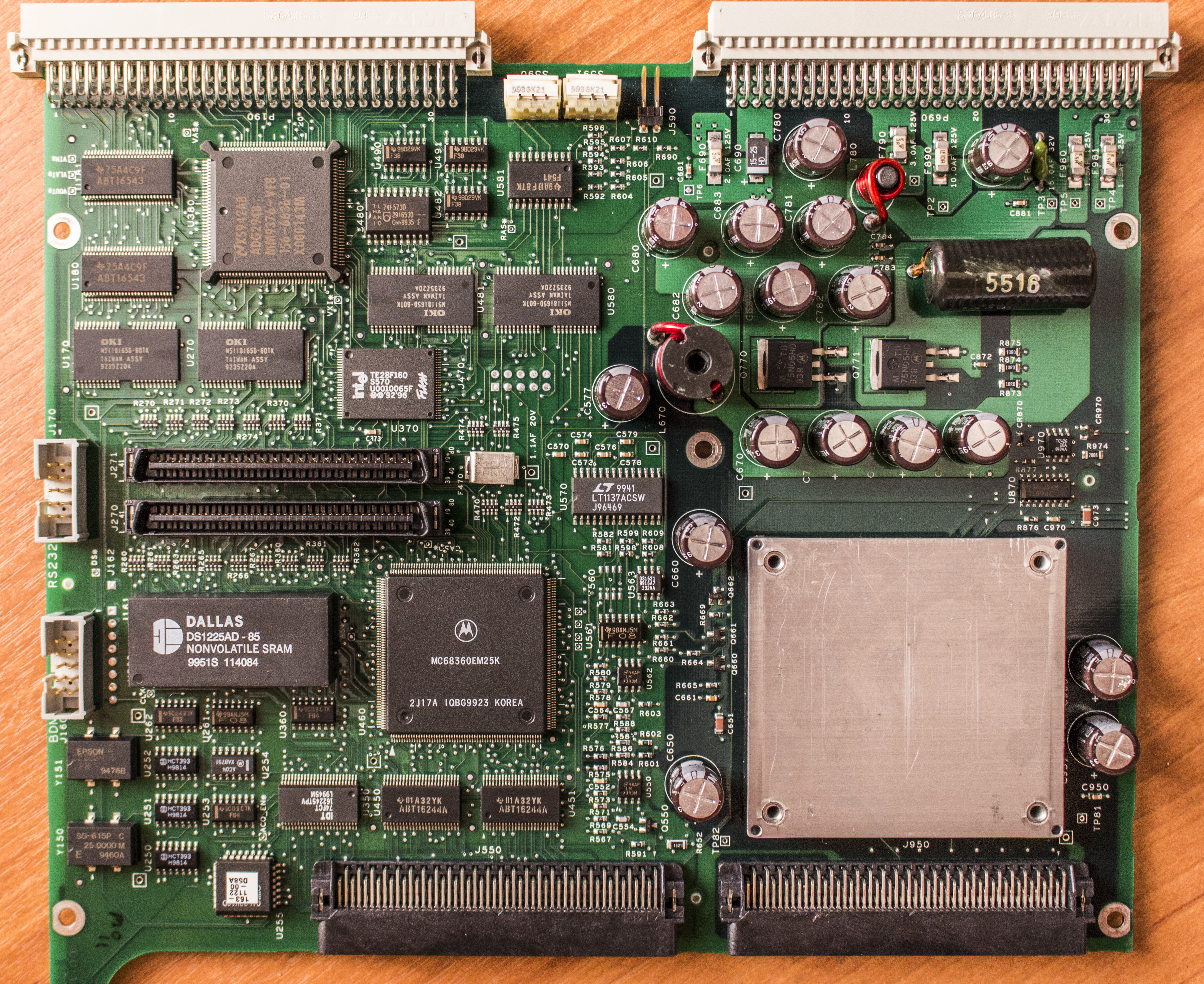
This board features microcomputer with all control and glue logic, to talk with mainframe and pass commands to high-speed logic on bottom board.
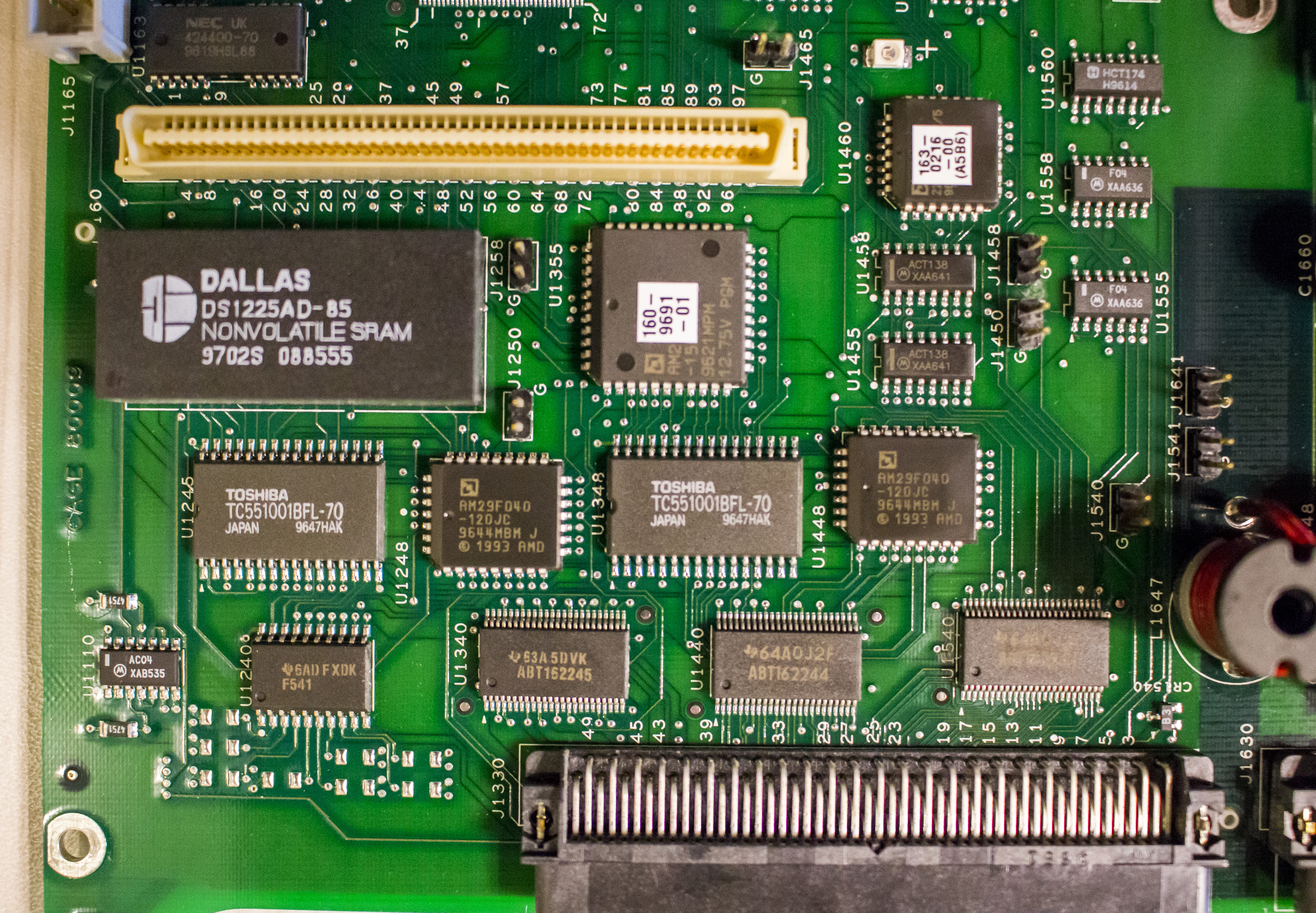
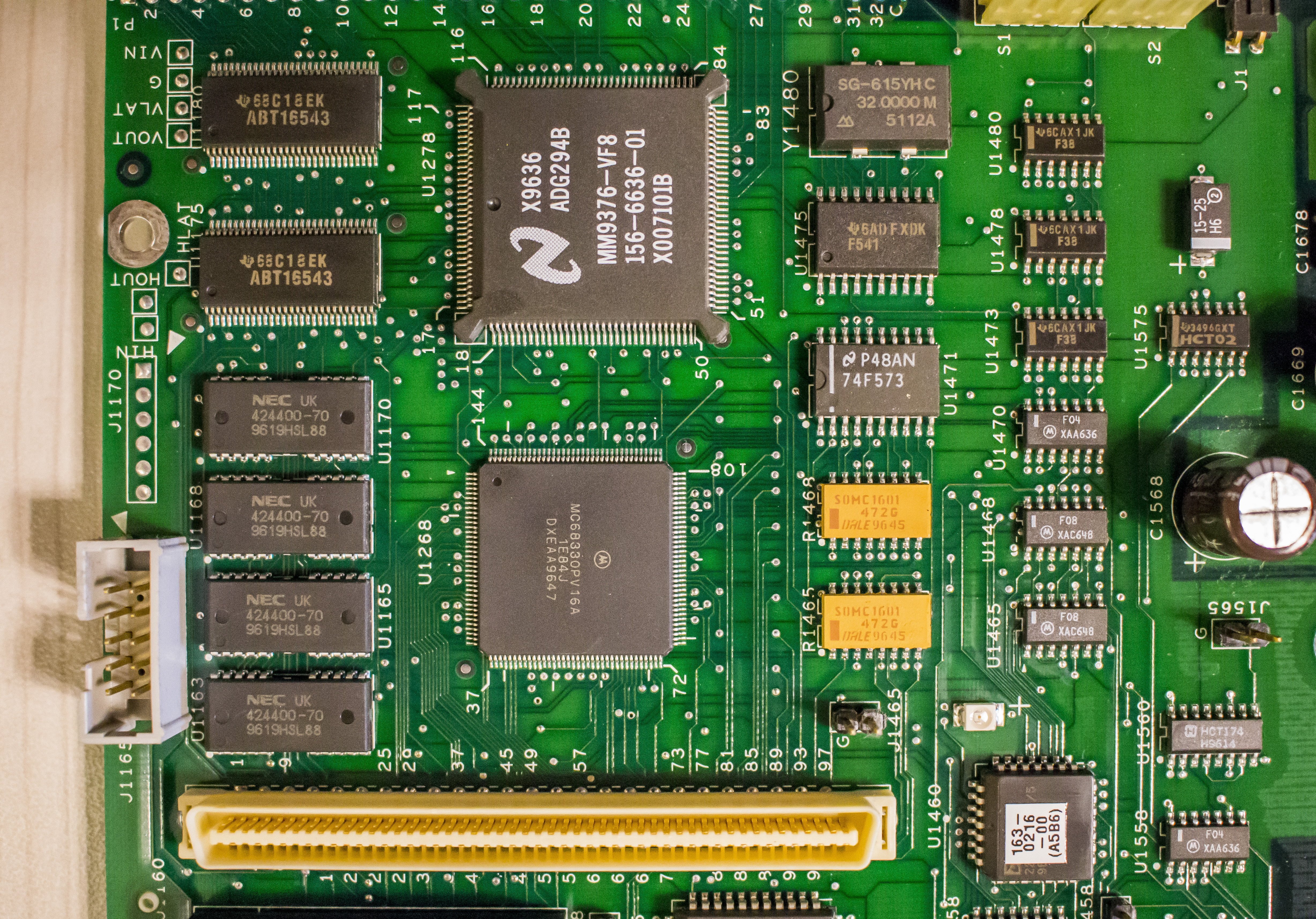
It is using MC68330PV16A processor, some National Semi custom logic chip ADG294B and bunch of NEC memory chips. All these chips are dated 1996, so this module is 20 year old. There is also Dallas NVRAM, DS1225AD-85, with date code 1997. It’s used to store calibration data, but since module can re-calibrate without need of external equipment, it’s not a big deal if NVRAM data get corrupted on these modules.
10-pin header connector J1165 seem to be serial console or a debug trace port.
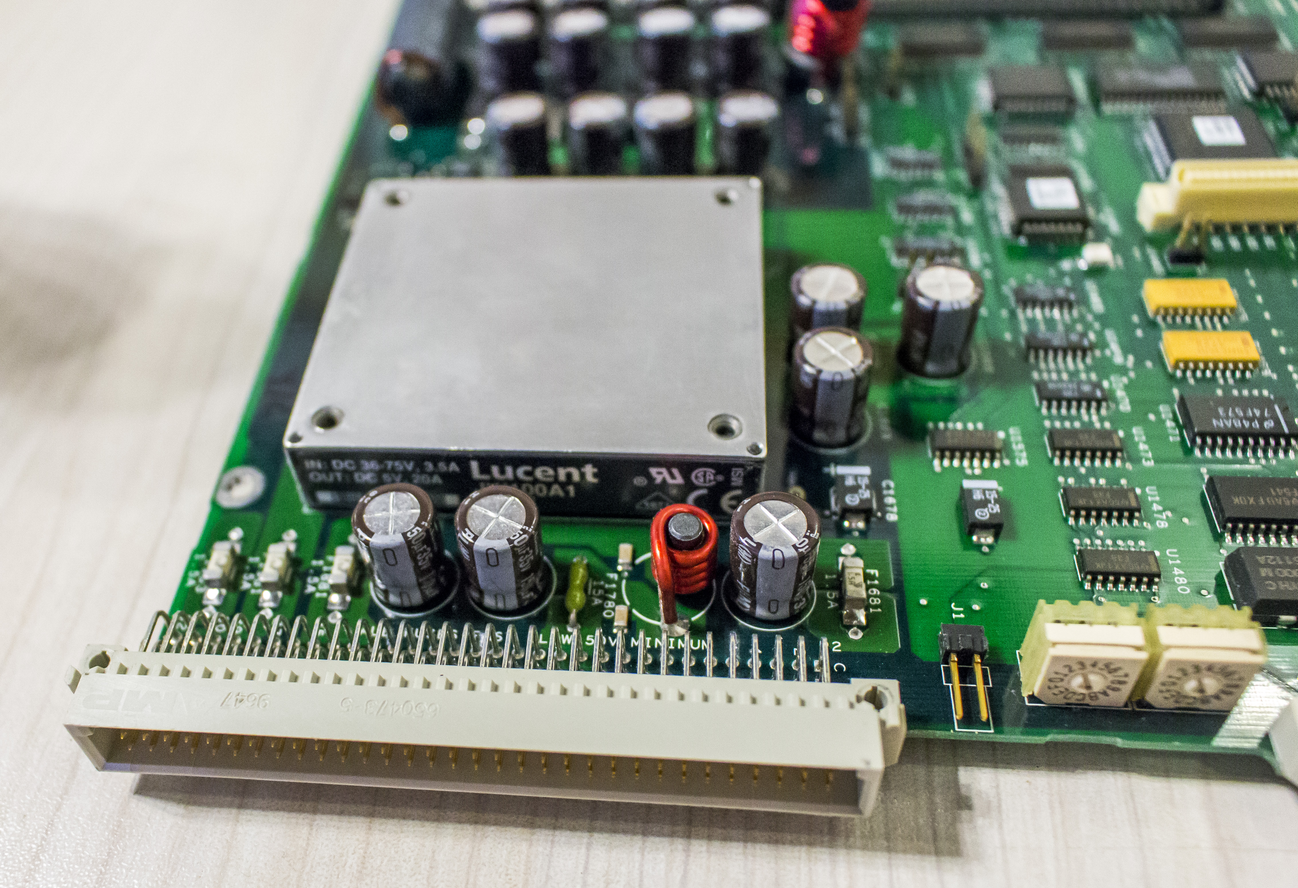
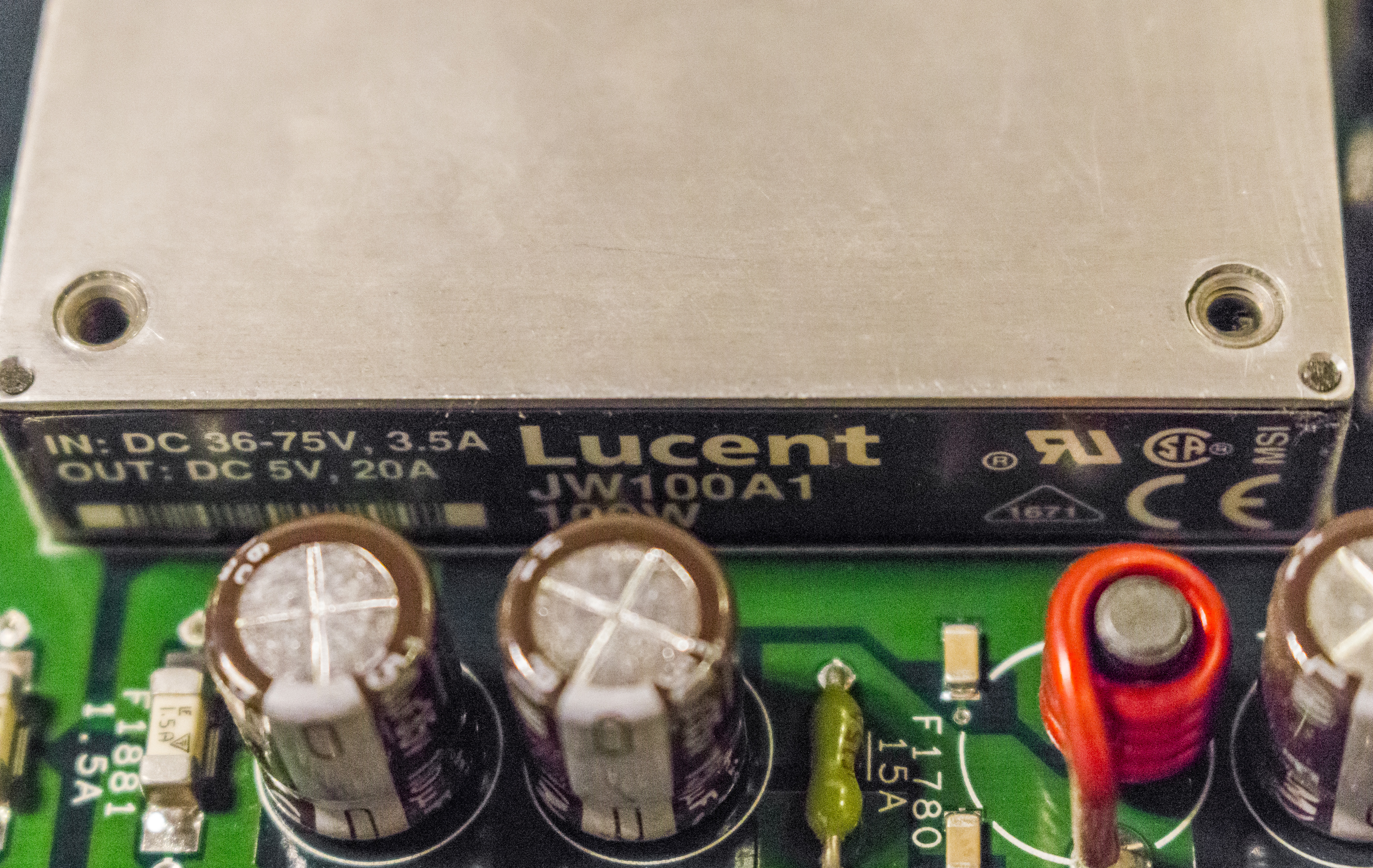
Big solid DC-DC module with input voltage rating 36-75VDC and 3.5A made by Lucent. It’s responsible for providing power to all parts in module, with it’s powerful 20A +5VDC output.

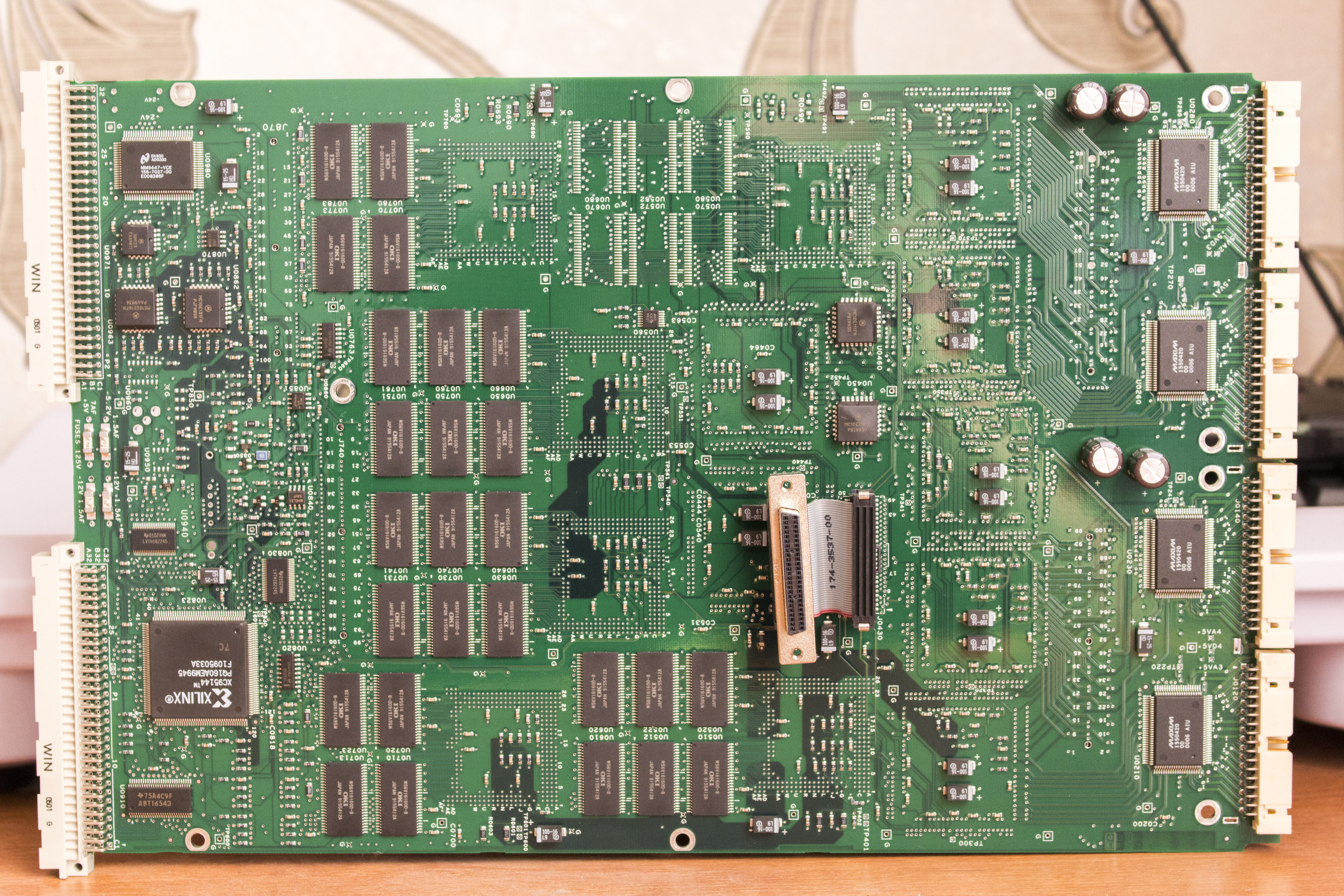
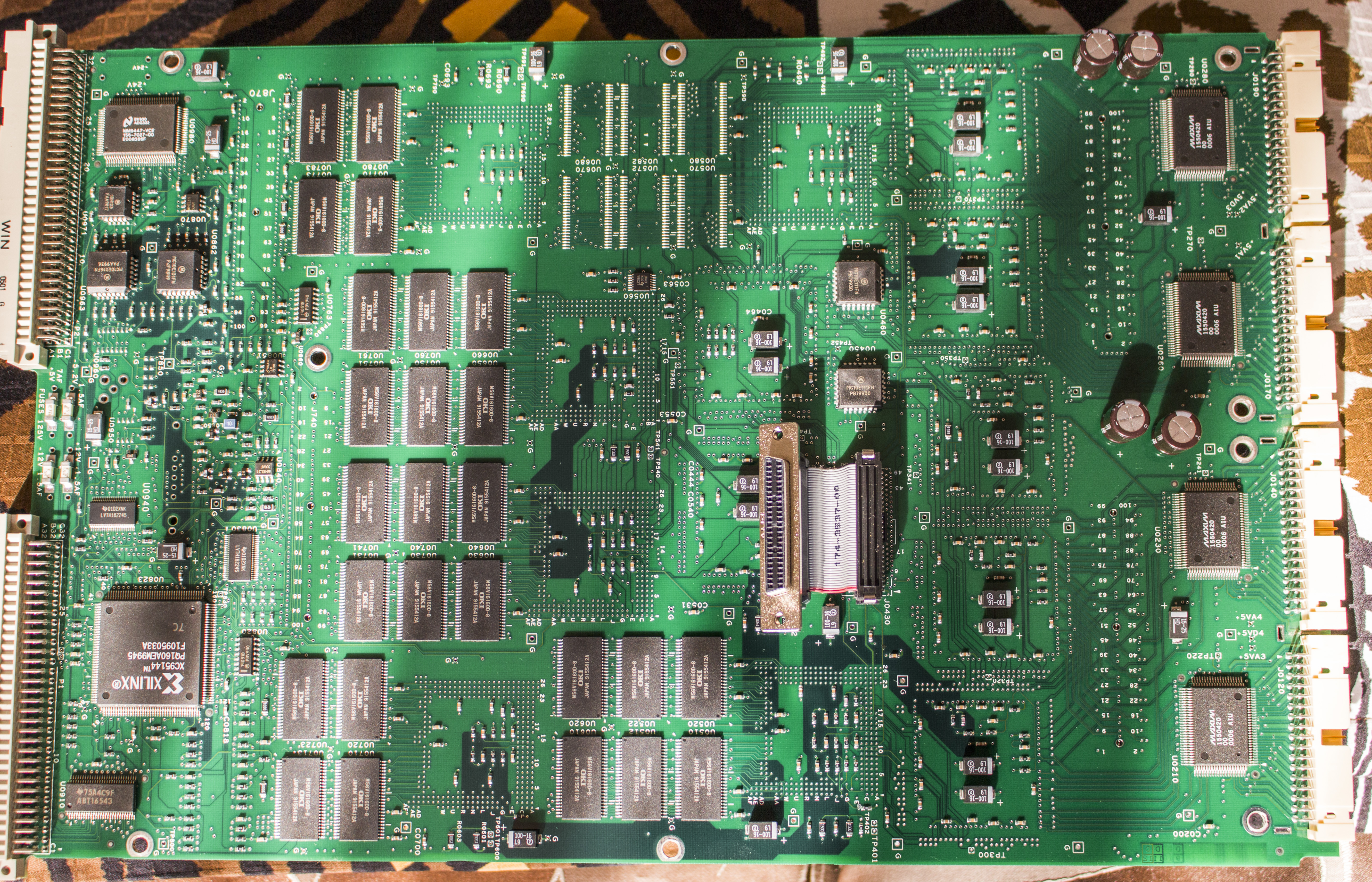
Let’s go back to main 12-layer board with all digital magic:
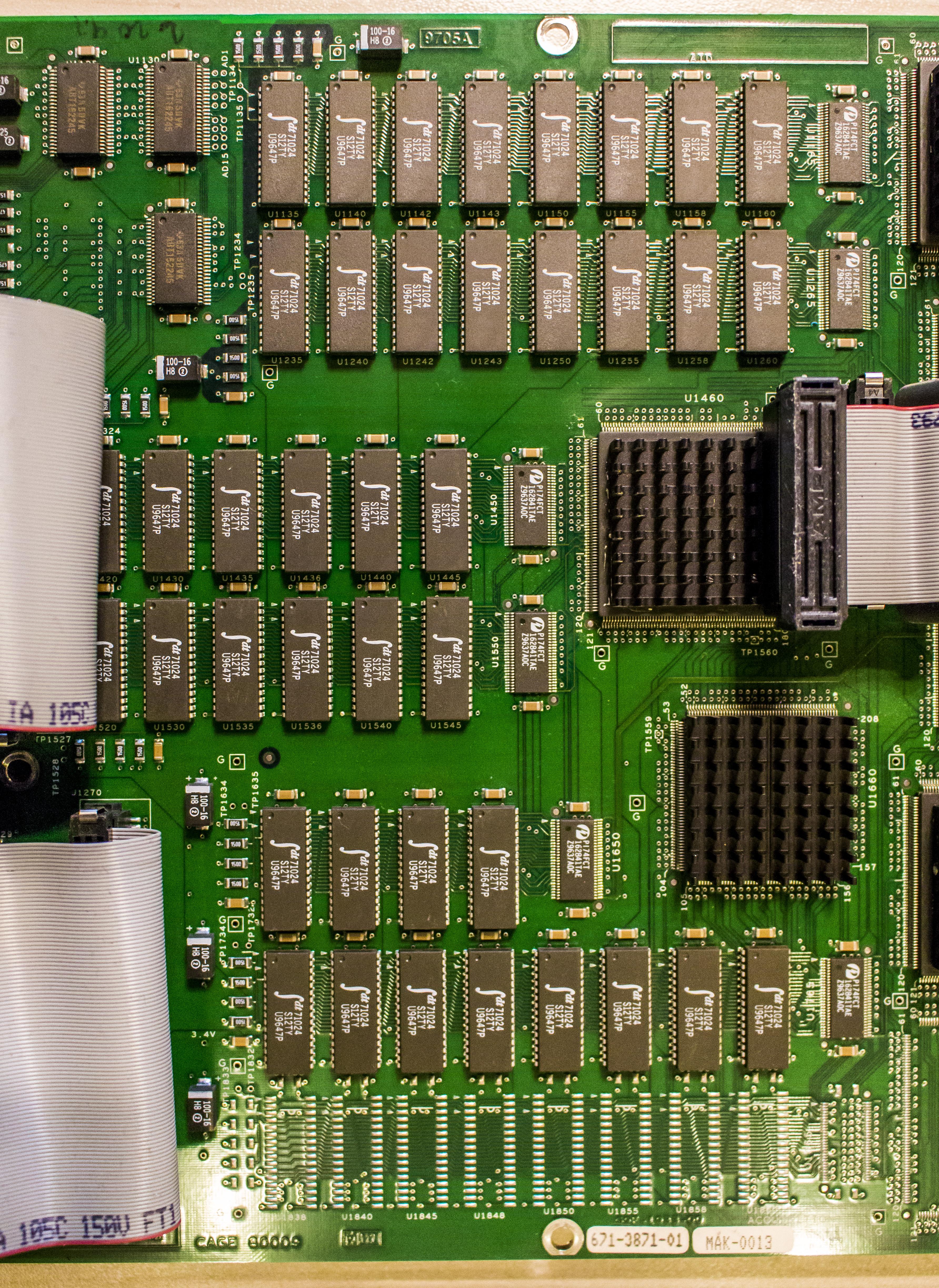
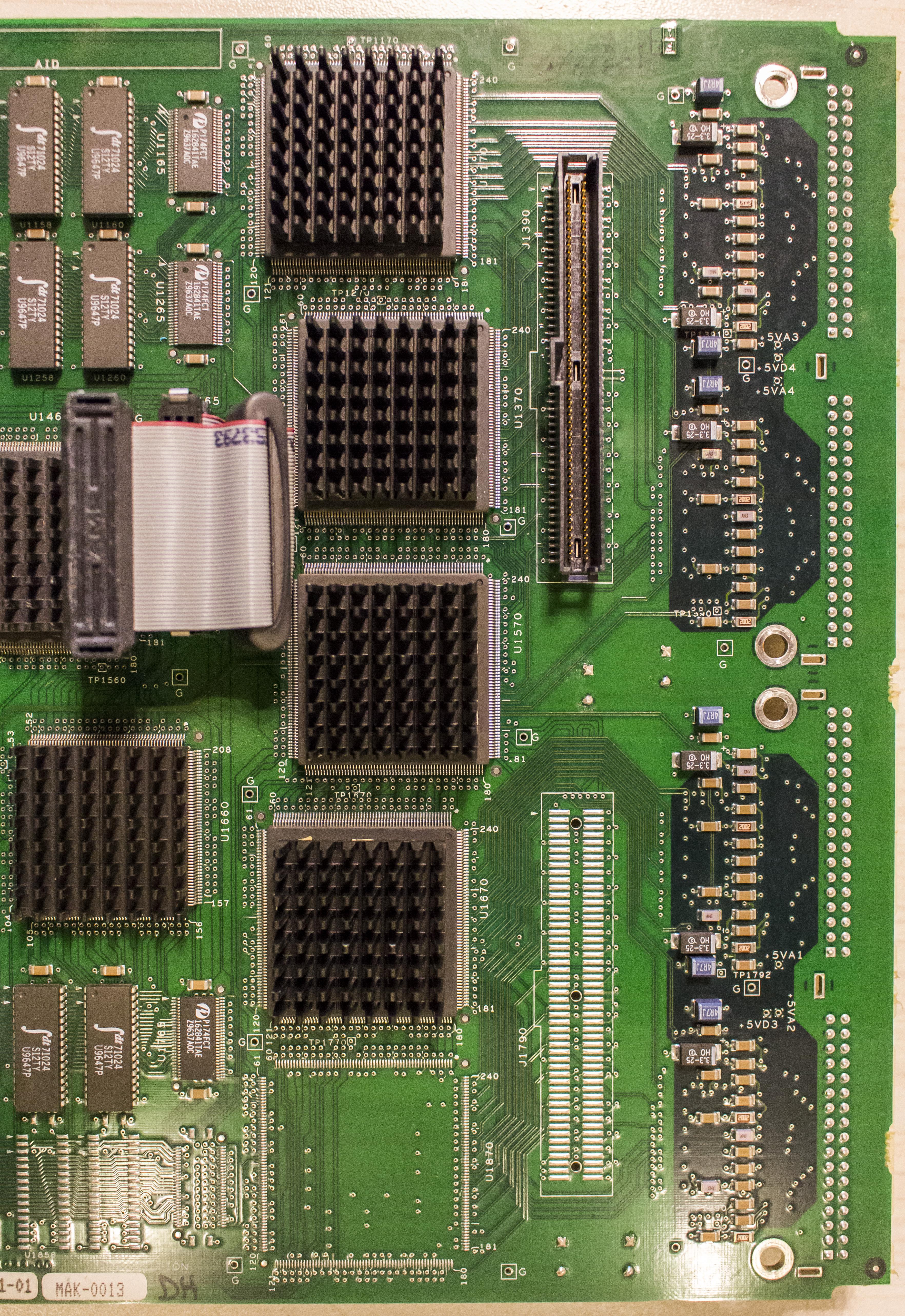
Input data is processed and converted by front end chips in large QFP package, cooled with massive heatsinks. Trigger chip is likely U1570 in center, tied to all front end ASICs. Also lot of memory in SOJ PLCC package populated around logic chips to store all those samples. One of banks is empty due to absent 34 channels. Some AMD PALs in PLCC and National Semi ADG332 do some glue logic for VXI bus. Module using +5V, -5.2V, -12V and +12V supplies, according to test points and related silkscreen marks on PCB.

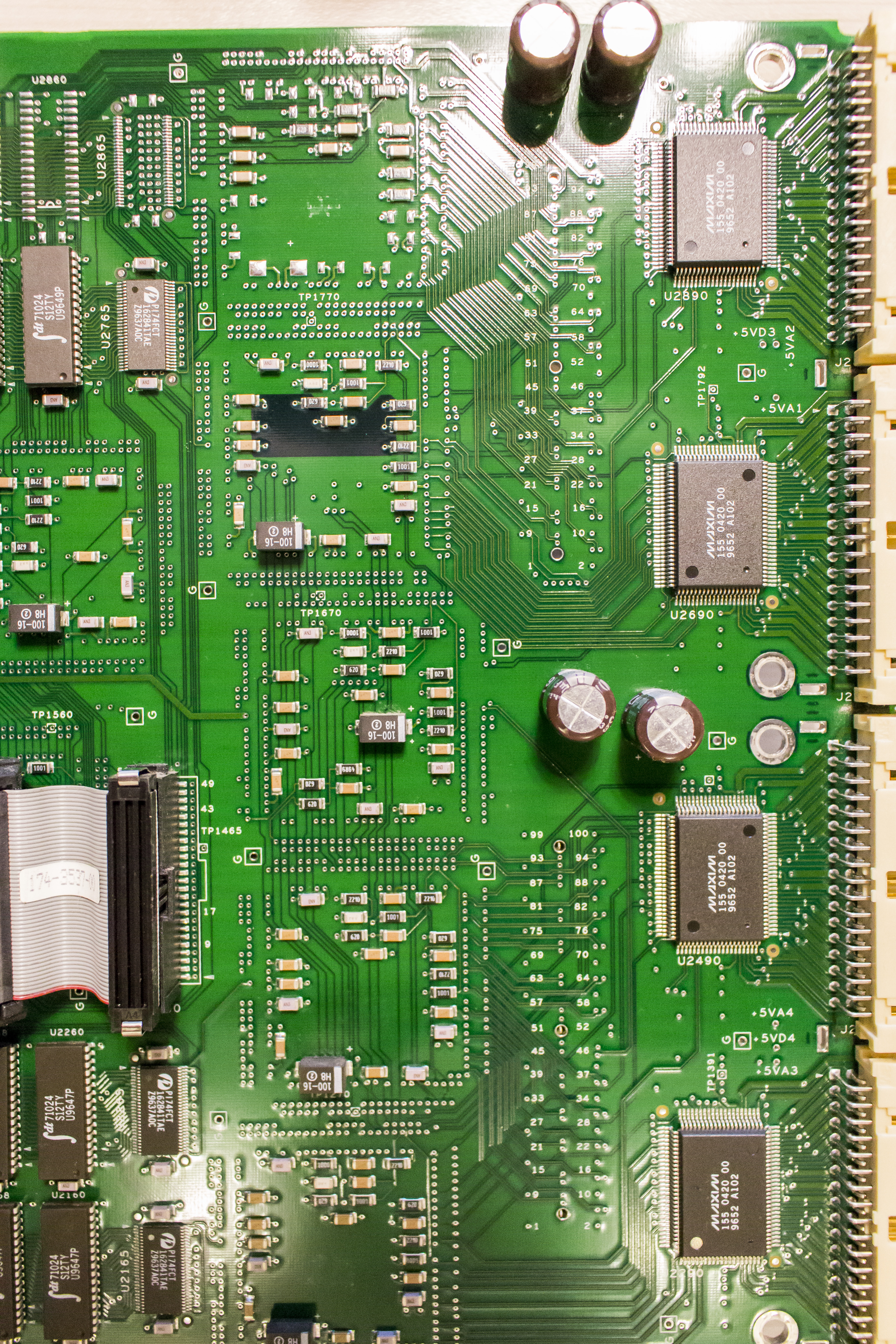

MAXIM chips in TQFP right at input channel connectors are high-speed custom comparators, to pass input signals with according to preset trigger level. There are one chip per every 34 channels. There few more digital buffers and also lot of SRAM banks on bottom side.
TLA7N3 module
Tektronix TLA7Nx series logic analyzer modules were released in 2005, some 11 years ago and can fit any TLA700/7000 series mainframes. These modules have 0.1” (2.54mm pitch) headers at input ports making custom pods interfacing easy and cheap. Probes which Tektronix sale for these modules are P64xx series.
- 102 Channel Logic Analyzer with up to 4 Mb Depth
- MagniVu™ Acquisition Technology Provides 2 GHz (500 ps) Timing Resolution to Find Difficult Problems Quickly
- Up to 200 MHz State Acquisition Analysis of Synchronous Digital Circuits
- 500 MHz Deep Timing Analysis with up to 4M Depth per channel
- Glitch and Setup/Hold Triggering and Display Finds and Displays Elusive Hardware Problems
- Transitional Storage Extends the Signal Analysis Capture Time
- Full Range of General-purpose and High-density, Non-intrusive Probes
Exterior and interior
Let’s take a look on the module exterior.
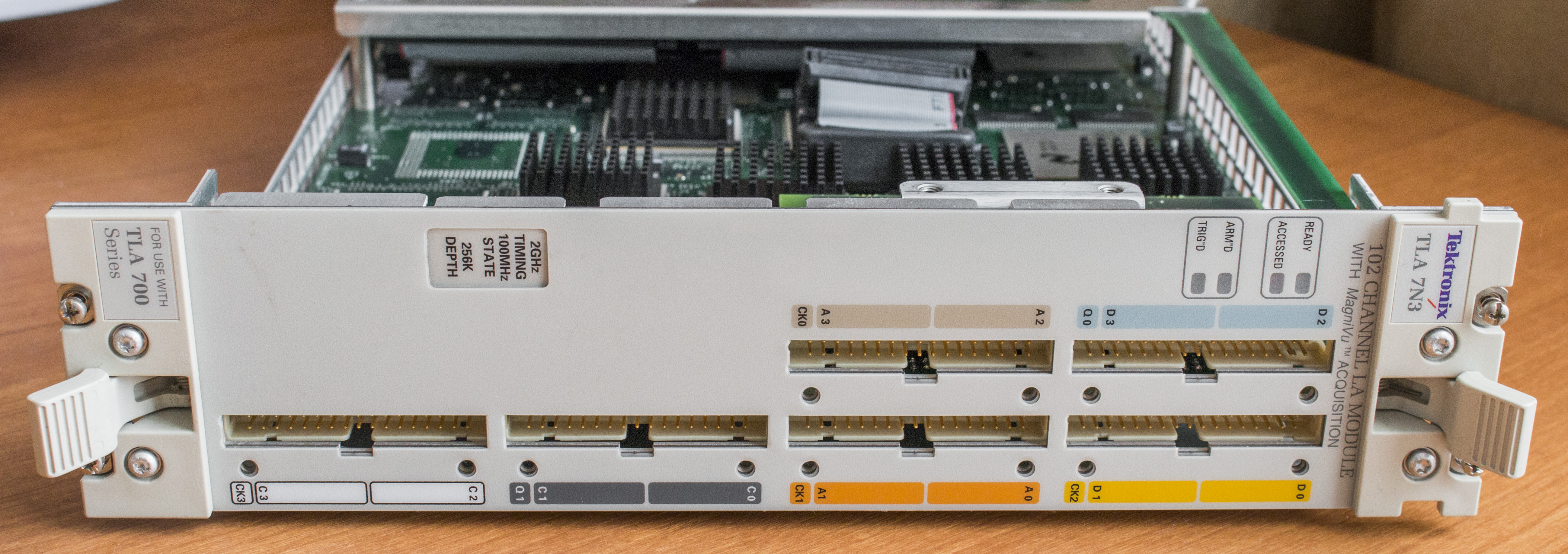
Face is similar to any other double-size VXI module, designed to fit TLA 700 and TLA 7000 series mainframes. Since it’s reduced version with only 102 input channels, there are 6 input connectors, each with 34 pins. There are four LED indicators for various module status reports, and label with speed and depth configuration. Module locks in mainframe with four screws on sides.
It’s all very same looking to older 7M3.
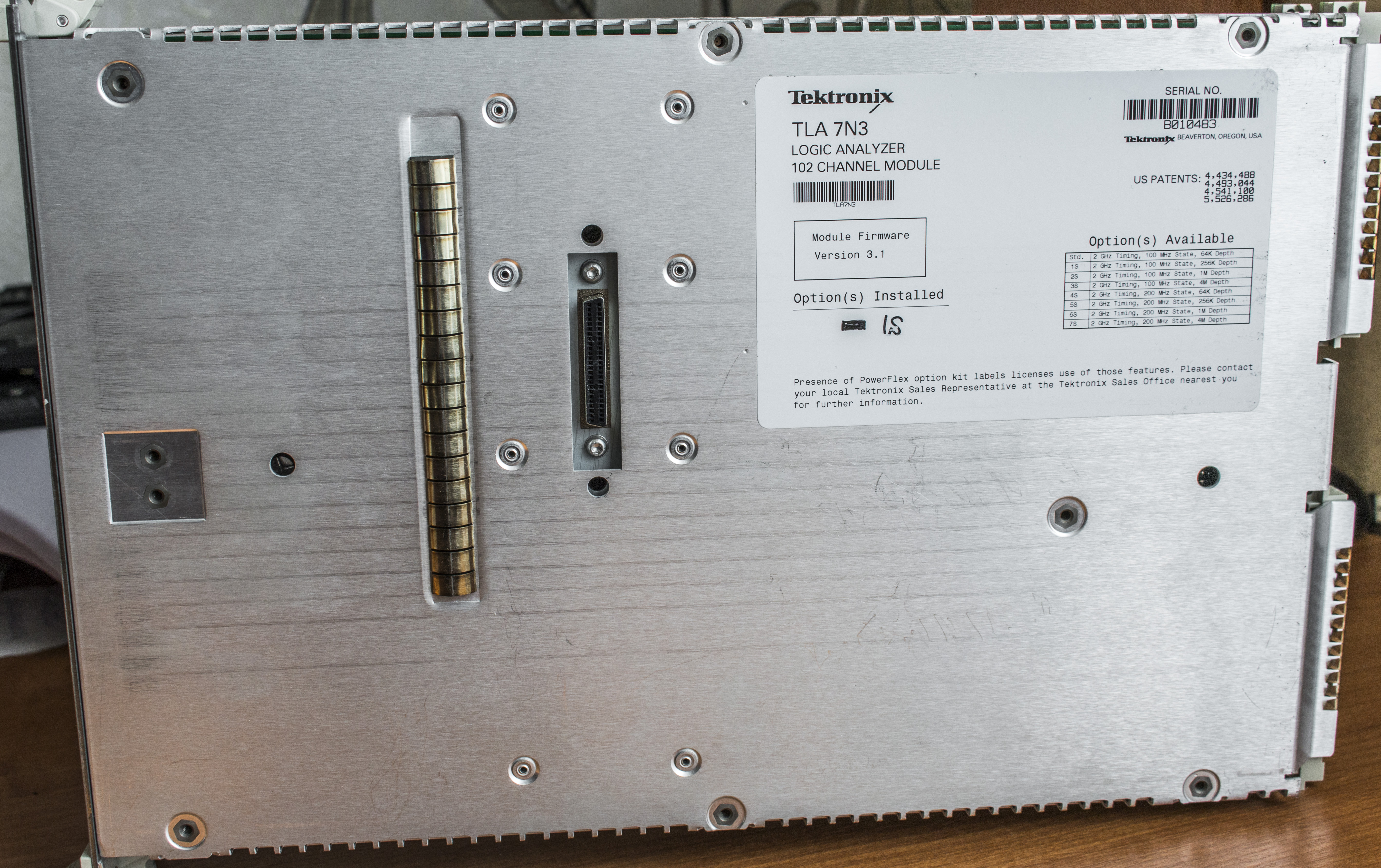
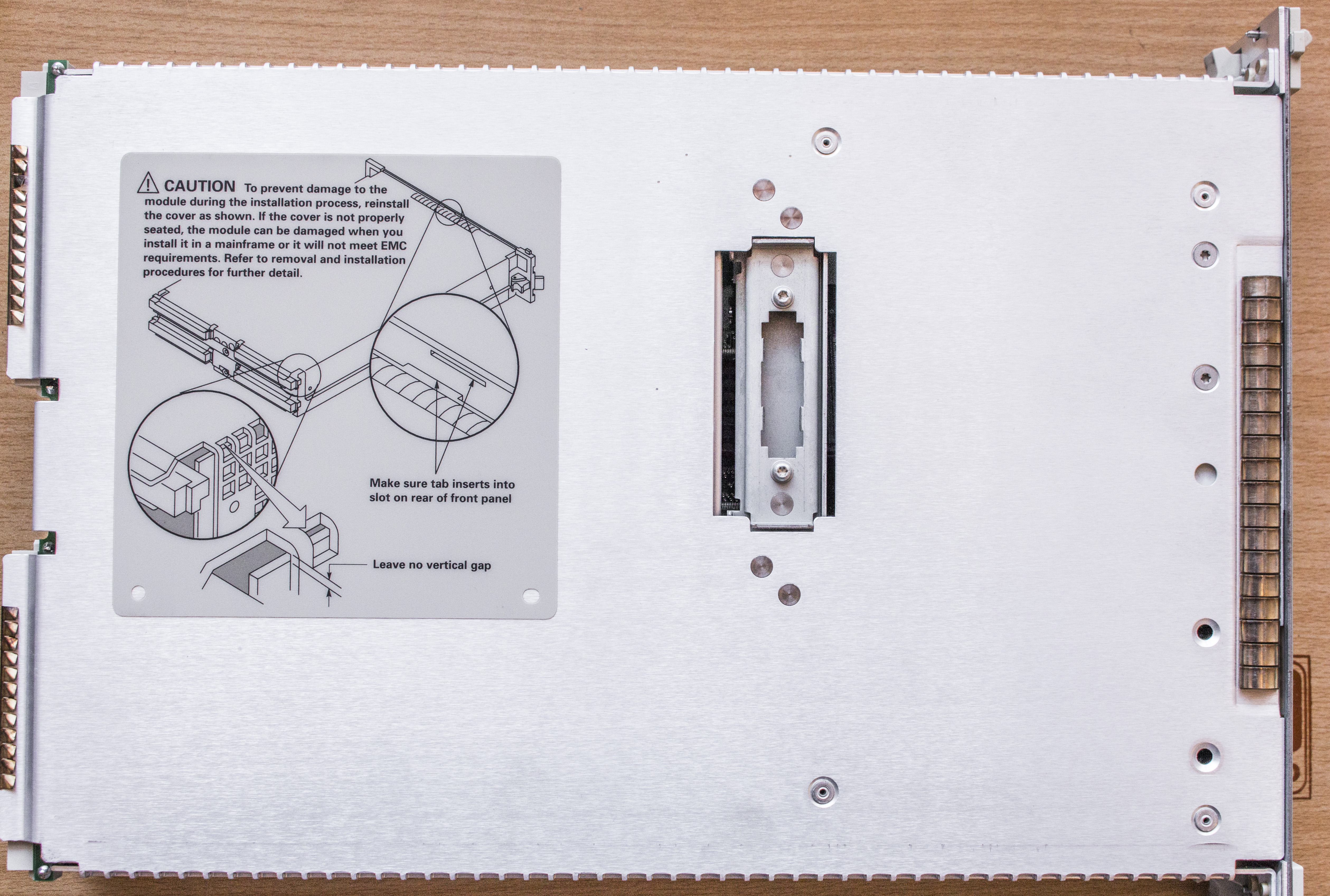
Side aluminum panels have installation note and label with module name, serial number and option configuration. There is merge module connector, to allow inter-module triggering and sync.
Module is easy to disassemble with Torx screwdriver.
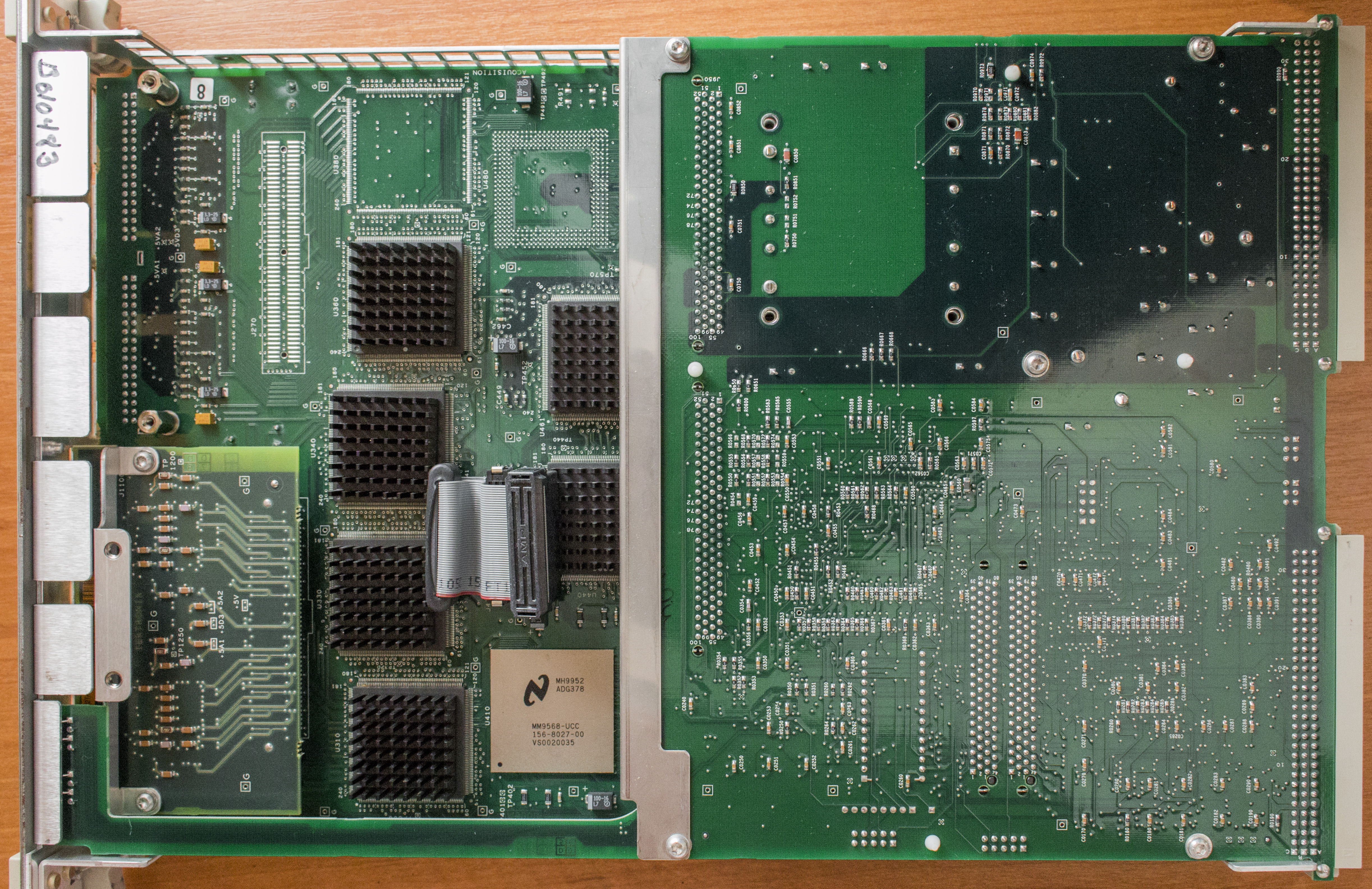
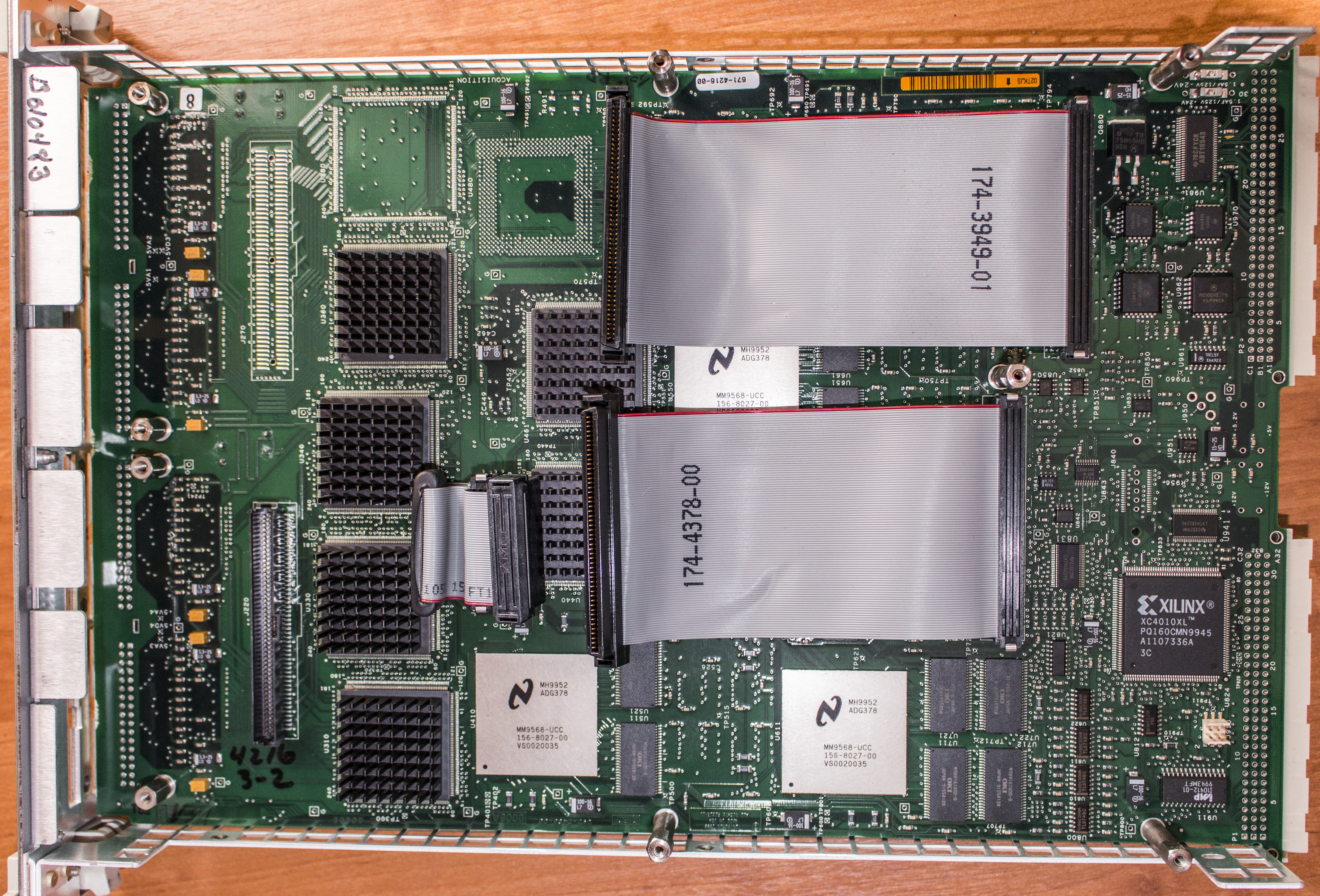
Inside it’s rather packed with two large multilayer PCBs. Smaller TOP PCB is digital controller, very similar, if not same to one we can find in newer TLA7AA4 modules.
Bottom PCB have all main acquisition logic, triggering system and storage memory, as well as input signal conditioners. Second level inputs are routed thru small daughter PCB. TLA7N4 module would have two of those instead for additional 34 channels.
It’s very similar to previous module, TLA7M3
Now, take a look at digital controller:
It’s based on familiar Motorola (today NXP) 68360EM25K Coldfire series processor. We already saw very similar board in TLA7AA4 review There is RS232 serial console port (J170) at board side, and BDM debug port.
This system runs vxWorks real-time OS, as many other Tektronix instruments and scopes of that timeframe.
Date codes on this module are year 1999.
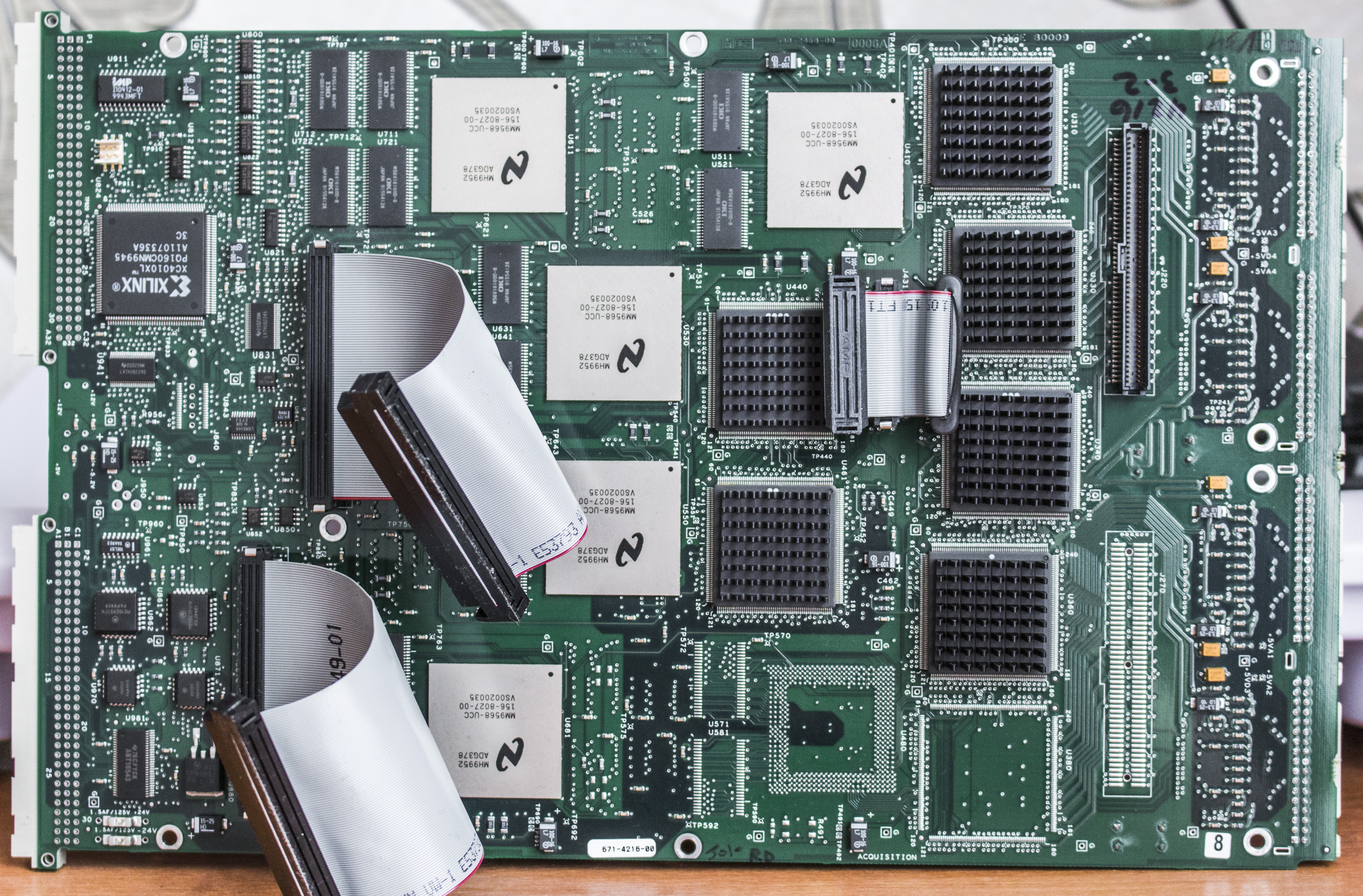
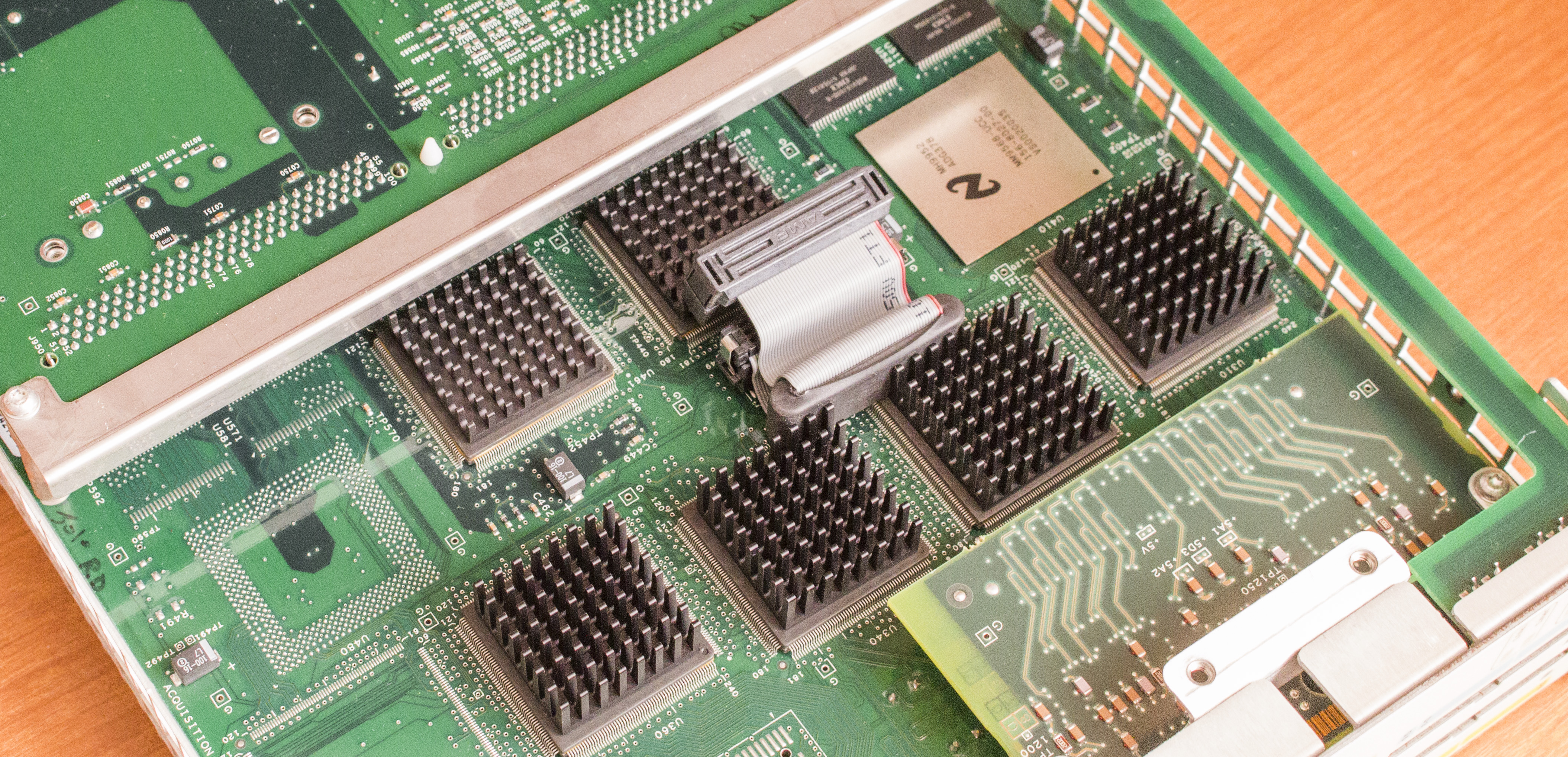
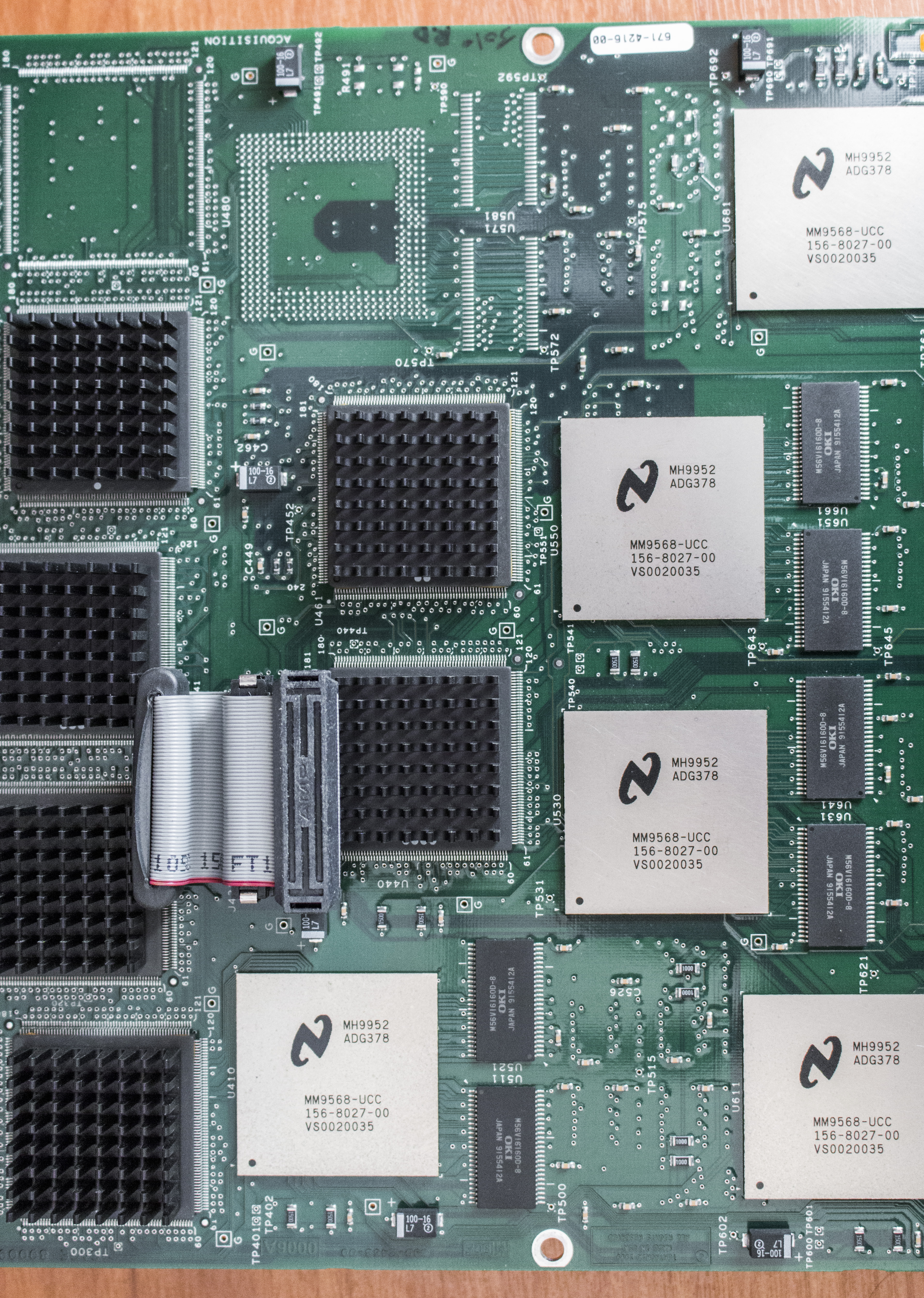
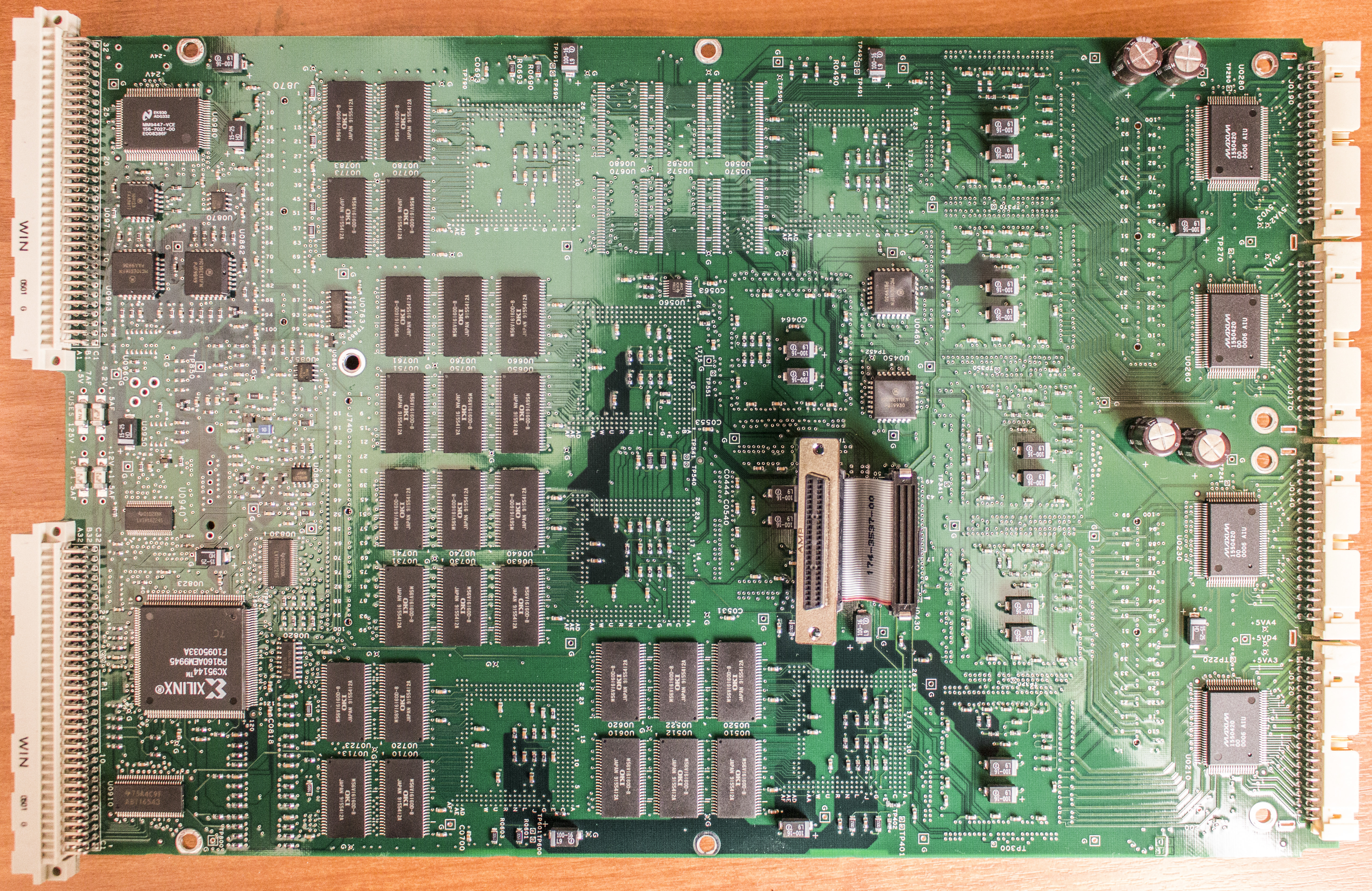
Main PCB have bunch of large National Semi ASICs, likely for fast memory storage and processing. Three QFP chips in center are triggering logic, tied to front end. Front end have one large QFP per every 34 channels. Since one bank is absent, related components are not populated on PCB. This board connects to digital controller board with two flat-ribbon cables.
Few close-ups :
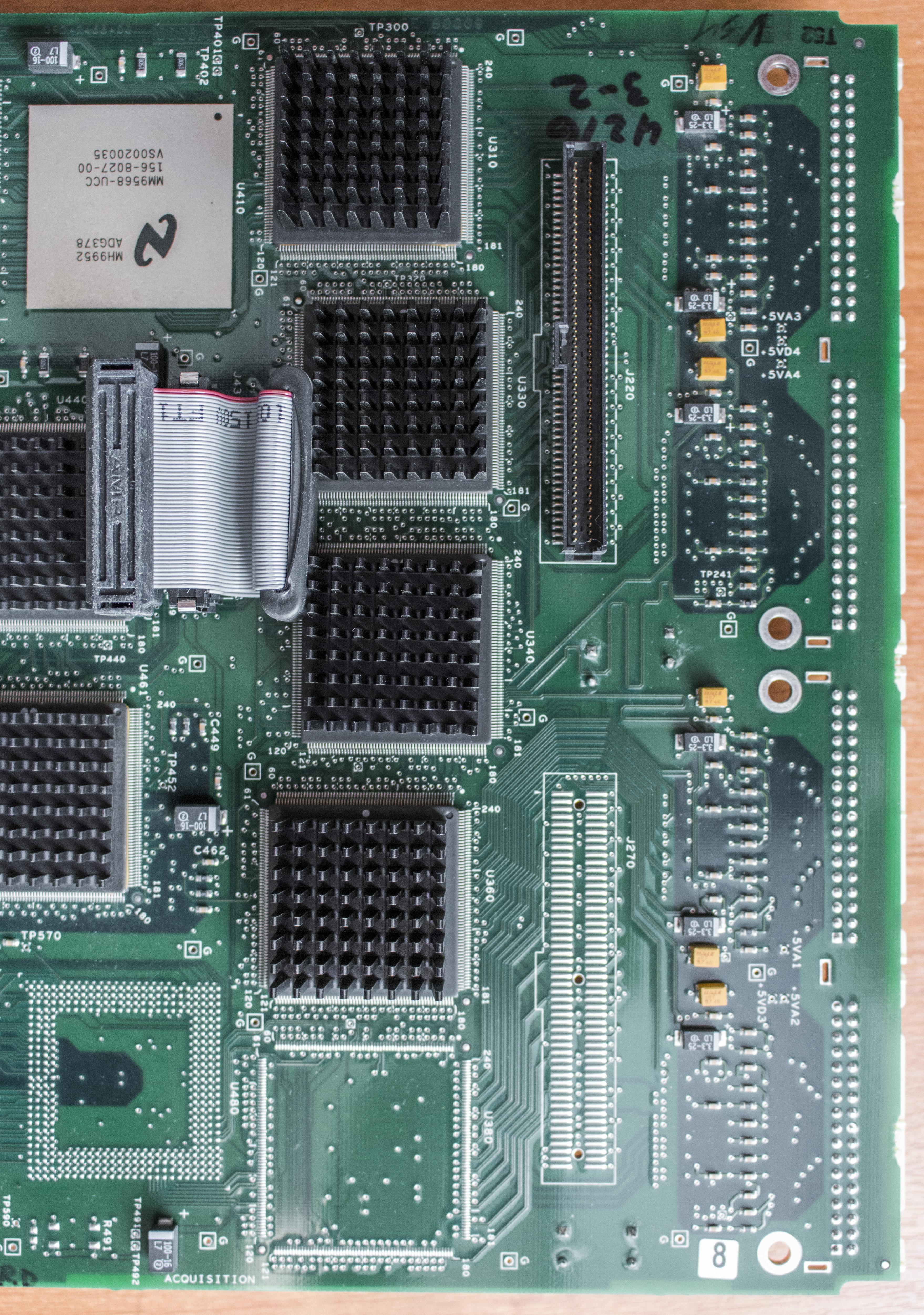
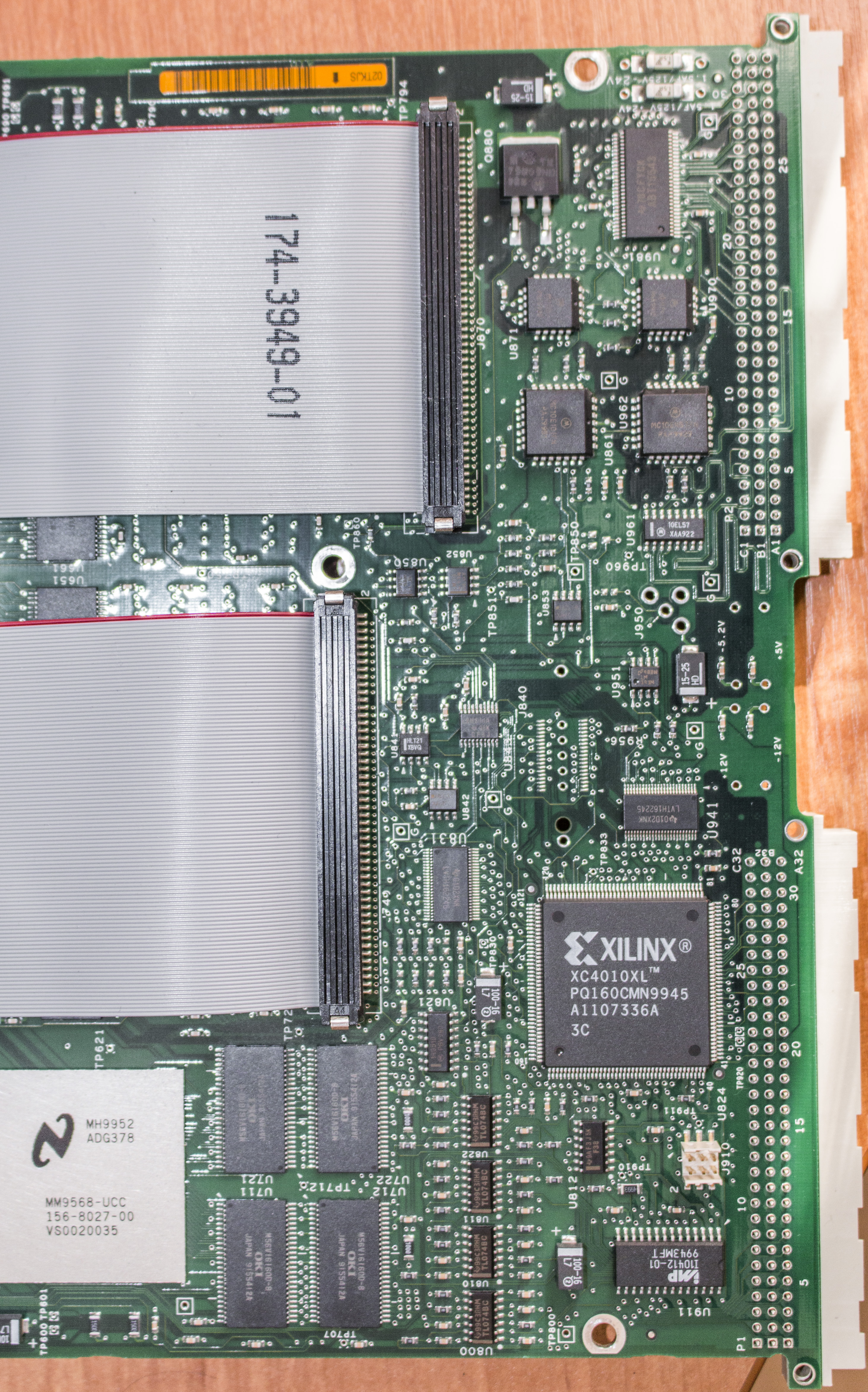
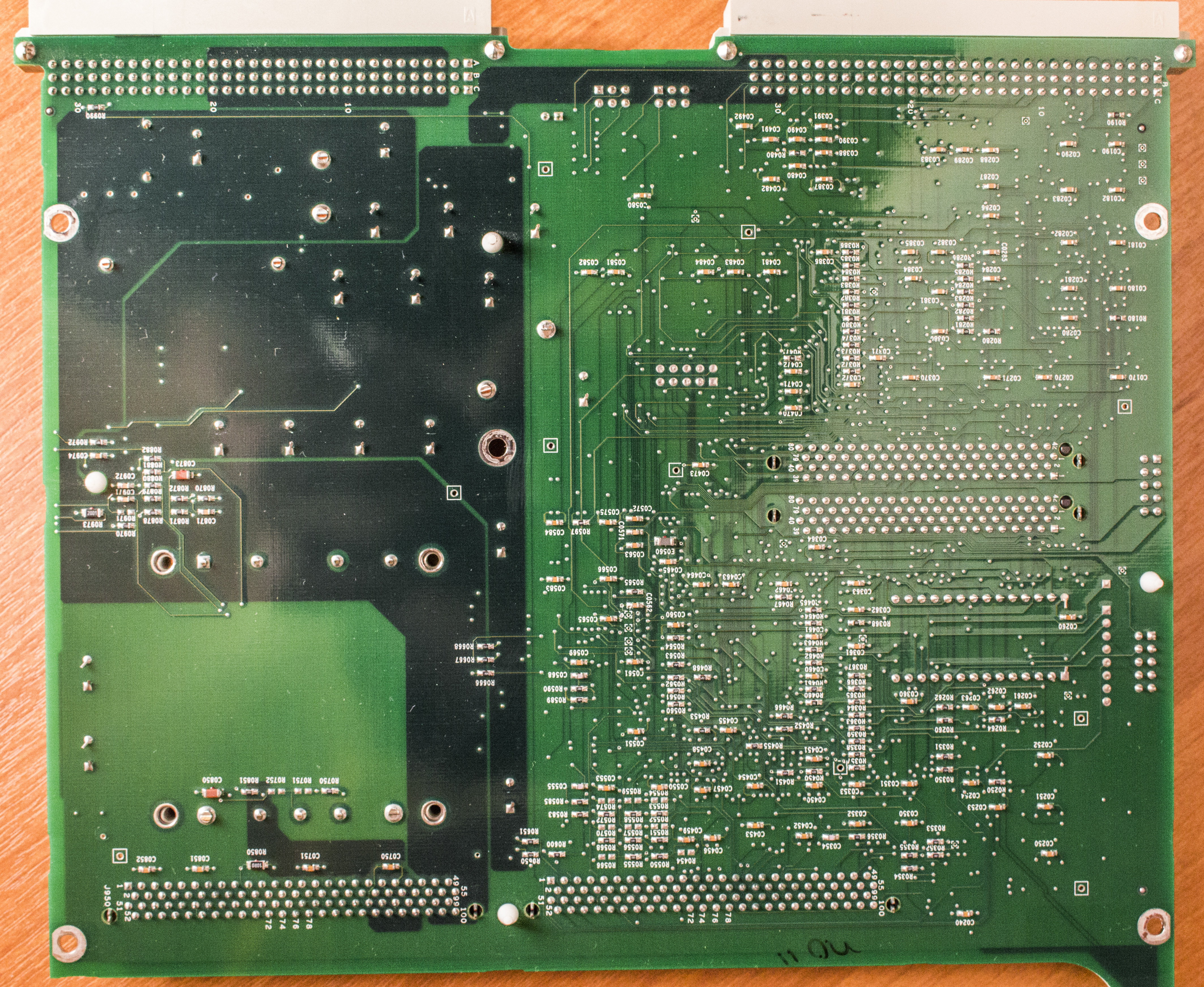
There is also some Xilinx FPGA clue logic for VXI interface and lot of small logic packages around. Few extra photos of rear side with memory banks are also taken, pick best one (one, second, third photo).
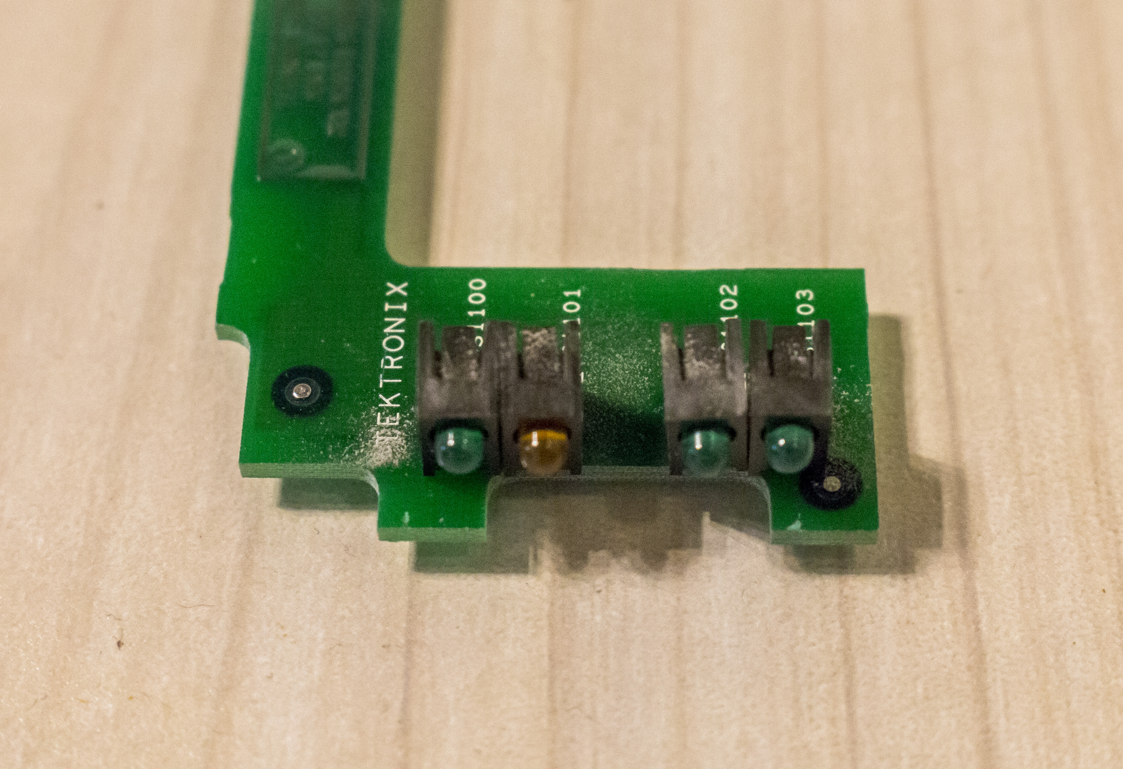
Same front-end daughter board, as we saw in TLA7M3:
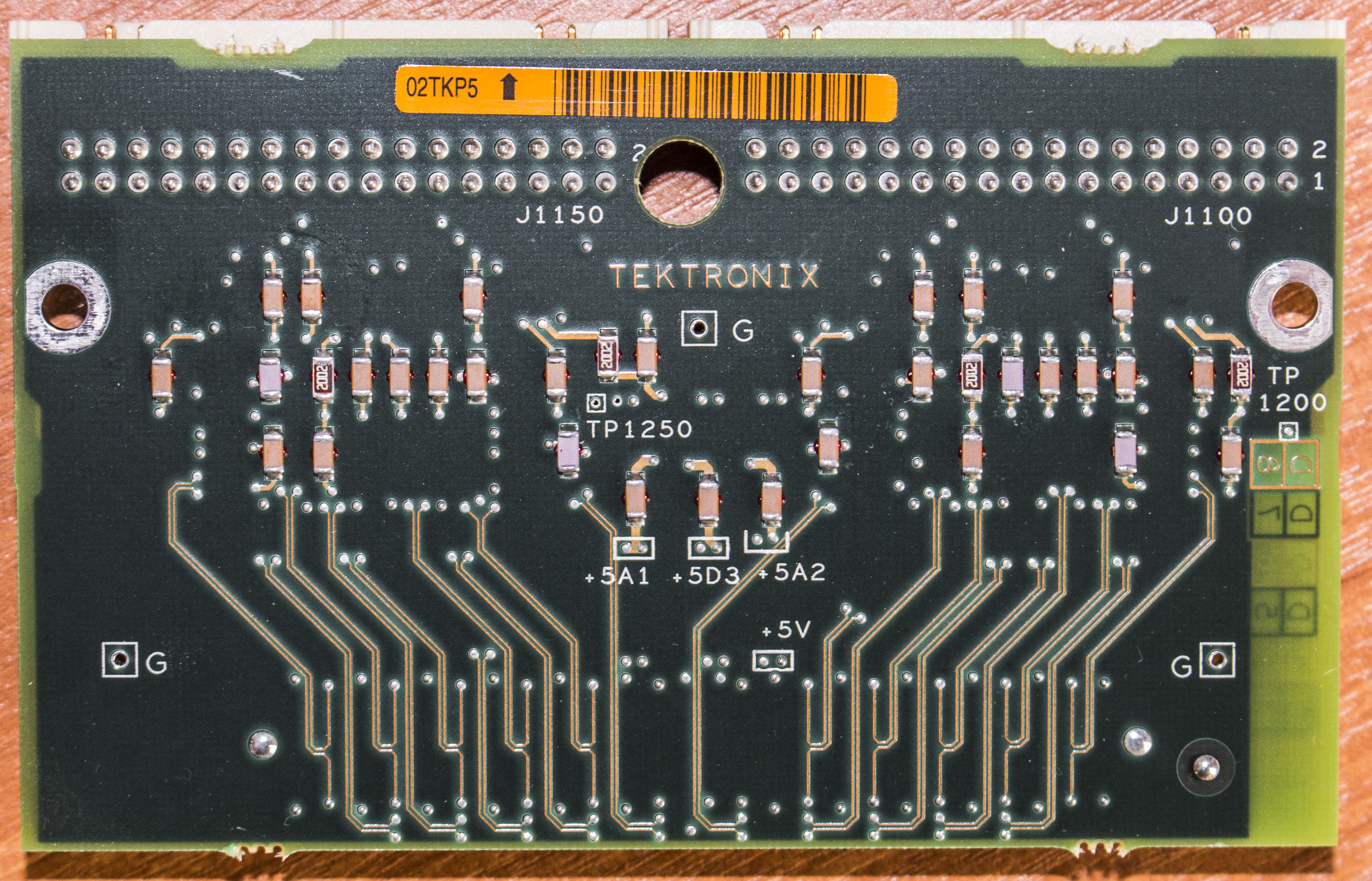

It just have two comparators for level triggering and detection.
Options
Since both modules and TLA714 are all out of support and EOL long time ago, here are procedures to test various options with TLA7Mx and TLA7Nx modules:
- Start the TLA instrument and then connect to it locally or remotely. In examples below remote operation was shown.
- Run “OpenChoice Talker Listener”. If you are doing this remotely, IT IS IMPORTANT you quit the TLA Application once the Openchoice Talker Listener shows your remote modules, both applications cannot access same mainframe simultaneously.
- Under the upper leftside pane “Instruments” you should be able to see your various modules listed.
- On the upper right side you will see an entry field titled “Enter Command or Script” referred from now on as COMMAND. Enter in the COMMAND field *IDN?
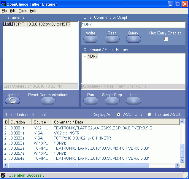
- Module should reply with it’s ID, like TEKTRONIX,TLA7N3,B010483,SCPI:94.0 FVER:5.5.001. Value of firmware version FVER will be needed later, so it’s important.
- We can check if module supports upgrades with TLA PowerFlex Utility:
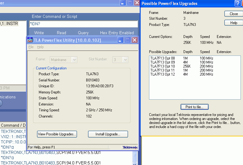
- Target is visible now, we need 4M depth with 200MHz state speed, which is maximum possible on TLA7N3
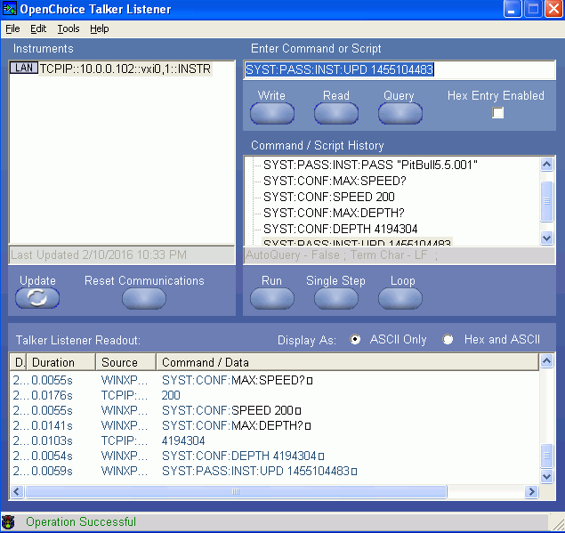
- To determine your maximum State speed in MHz issue this COMMAND then click “Query” and make note of it as
:
SYST:CONF:MAX:SPEED?
- To determine your maximum Memory depth in bytes issue this COMMAND then click “Query” and make note of it as
:
SYST:CONF:MAX:DEPTH?
- Time-stamp is required. For 1/01/2016 you can use 1451649600, if not create a new unix timestamp. You can visit this website to get current unix time stamp.
- Make sure the correct module is selected under “Instruments” and enter the following commands into the COMMAND field. After each line, press the Write button under the COMMAND field. An Example of all commands will be shown after all the lines. Note: do not include the < > just the value. Use quotation marks when shown. Commands are case sensitive.
Total commands list would be:
SYST:PASS:INST:PASS "PitBull<VERSION>"  // Set Parameters Code: [Select]
SYST:CONF:DEPTH <DEPTH>
SYST:CONF:SPEED <SPEED>                      // Save Parameters: Code: [Select]
SYST:PASS:INST:UPD <TIME>
And working example, used on TLA7N3 above:
SYST:PASS:INST:PASS "PitBull5.5.001"
SYST:CONF:DEPTH 4194304
SYST:CONF:SPEED 200
SYST:PASS:INST:UPD 1451649600
- After commands are entered, you can exit OpenChoice Talker Listener and run the TLA Application and note your new upgrades. No reboot is required.
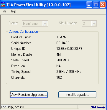
We can check correct upgrade by running TLA PowerFlex Utility again:
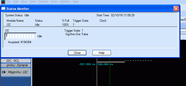
And just to make sure that everything is working fully, let’s run few tests on TLA Application:
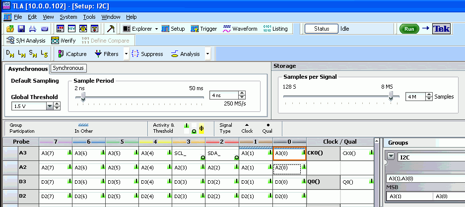
Here’s data capture with 4M depth set, showing 4194304 samples indeed captured:
Credits
xDevs.com would like to thank mariossd for provided photos and testing with his TLA714 and TLA7M3, TLA7N3. Also last section would be impossible without contribution of EEVBlog member dxl.
Modified: Feb. 11, 2016, 7:21 a.m.