In LEM (former Danfysik divison) precision current transducers, named ULTRASTABs, flux gate principle and state of the art wideband precision current measurement performance is archieved by Zero-flux detection technology.
Zero-flux detection
In the ULTRASTAB current transducers the magnetic field generated by the current flowing in a primary conductor is measured by counter balancing this field by means of the electromagnetic field generated by a toroidal coil. The precise counterbalance (the “zero flux”) is detected by a very sensitive magnetic flux detector. This detector in turn drives the current source, feeding the necessary value of ampere-turns in the field compensating toroidal coil.
There are usually two additional sensing cores, total making three-core inductor system. A magnetic modulator drives two of the sensing cores in and out of saturation. If there is DC flux in cores, current peaks will be unequal. This current peak asymmetry is measured and combined with the AC component measured by the third core. A control loop generates a opposite compensation current that zero the total flux. This compensation current is a fractional of the primary current going thru sensor.
This unique feature behind the compensation principle allow current measurement at extremely high accuracy. The limit is only set by the obtainable sensitivity in the magnetic field detector. Here’s reach the core capability of the UTRASTAB current transducers. Today a refined and proven zero flux technology able to detect magnetic field with a resolution of about 0.0000003 of the absolute value! Or said in other terms we can measure a DC current to better than 3 parts in 10 million (0.3ppm).
If you not impressed by now, check some of features which these current sensors have:
- Extremely high linearity in current measurement
- Very high absolute precision
- Very high reproducibility
- Extremely low temperature coefficient
- Very low intrinsic noise data
- Unsurpassed dynamic range
- Very wide bandwidth
- High common mode rejection
Let’s take a look on this mighty device more closely, on example of LEM ULTRASTAB IT 600-S , 600Amp variant. This is direct refresh of older Danfysik 866-600 unit.
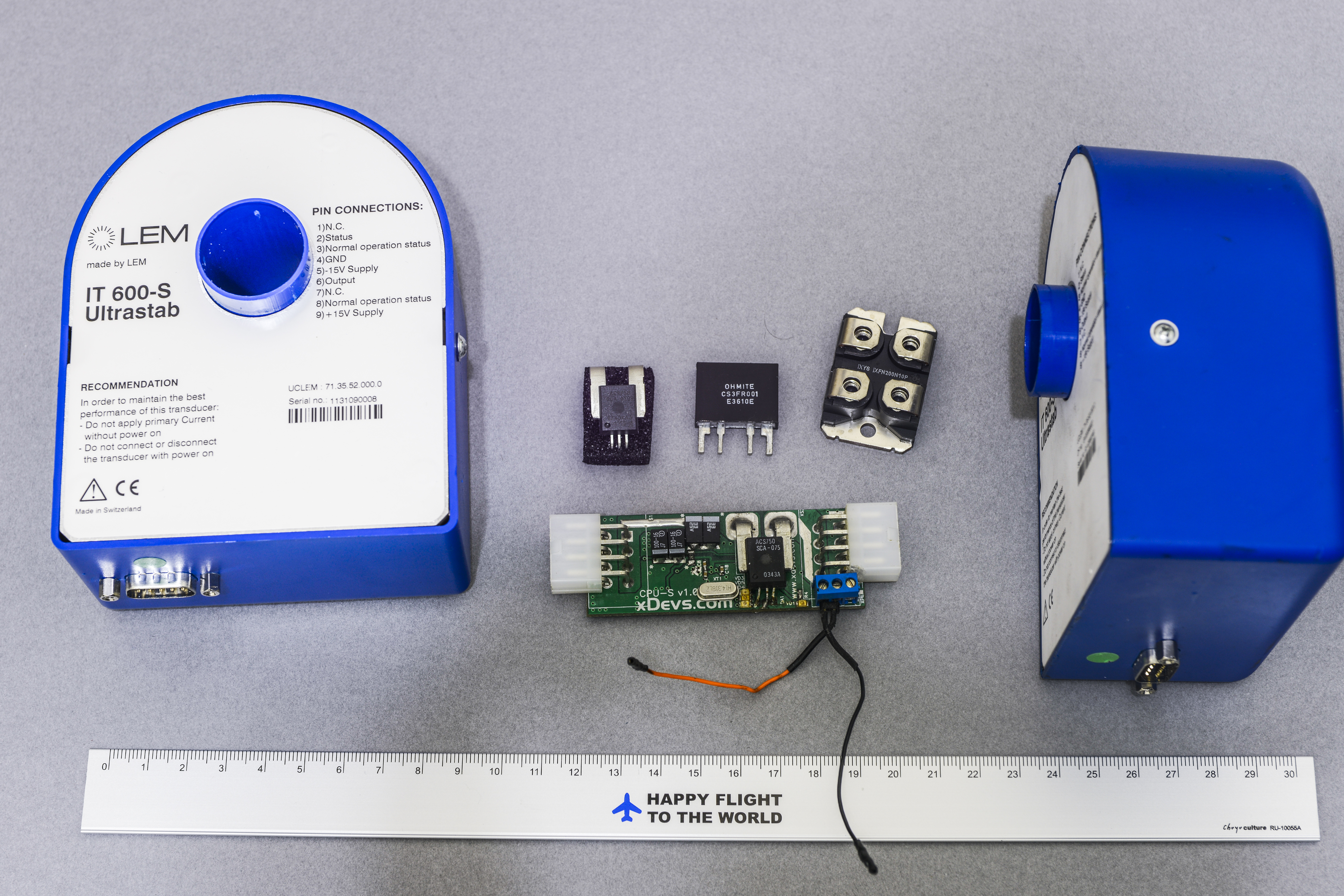
Here’s overview photo of two LEM sensors (blue big things on left and right) with few other current measuring devices, listed from left to right:
- Allegro ACS750 , Hall IC current sensor, linearity ±5%, total error ±2%, 13kHz bandwidth.
- OHMITE CS3F current sense resistor , Kelvin-terminal 1 mΩ specialized resistor, tempco 60 ppm/°C, resistance tolerance 1%
- MOSFET in SOT223 package, widely used in industrial applications
- Small power measured module with Allegro ACS750SCA-075 and ATMEL AVR ATmega8 microcontroller
ULTRASTABs pretty big, well suited into account of it’s enormous current rating.

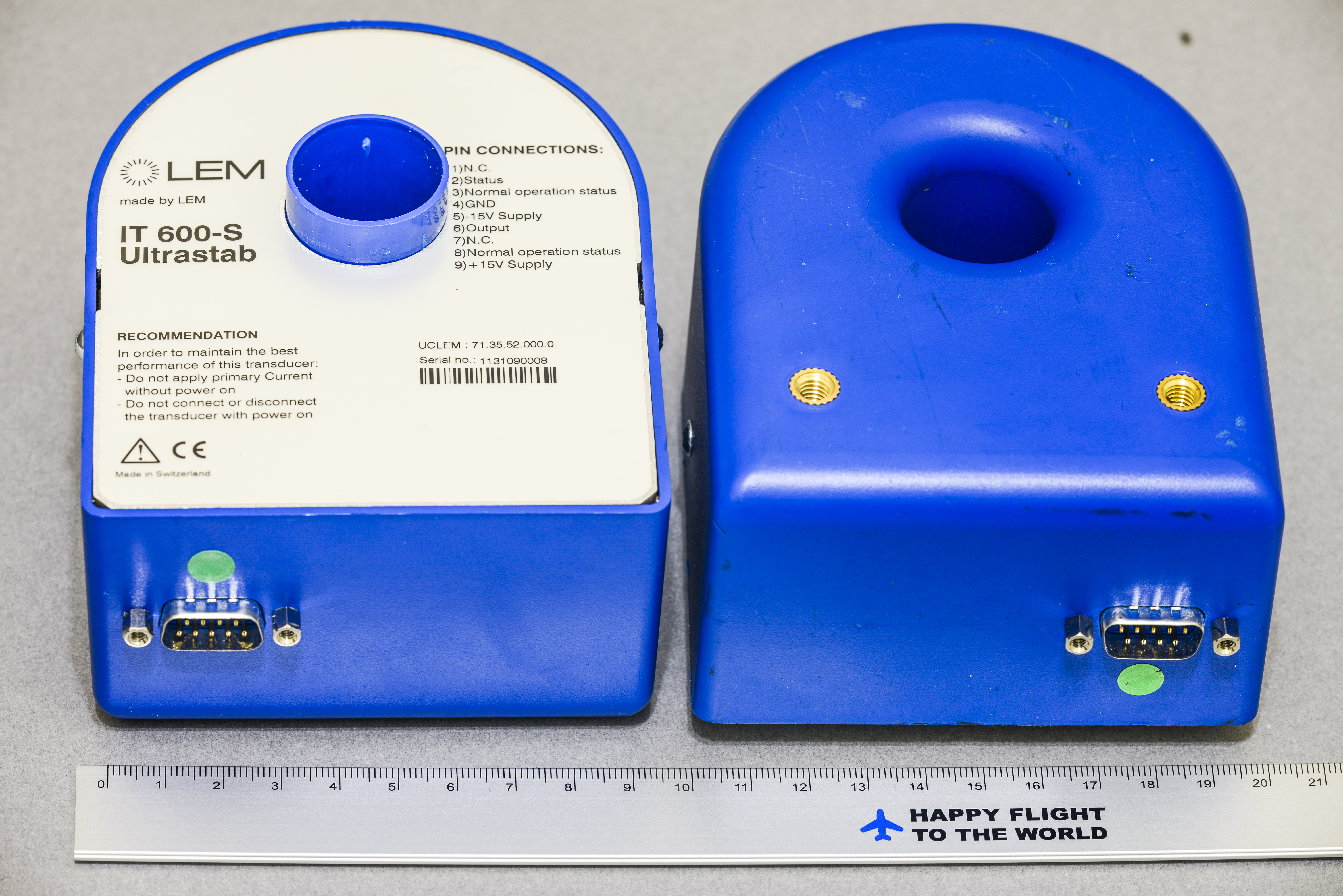
There is single DB-9 type male interface port to deliver power, connection burden resistor for secondary current output and status signaling.
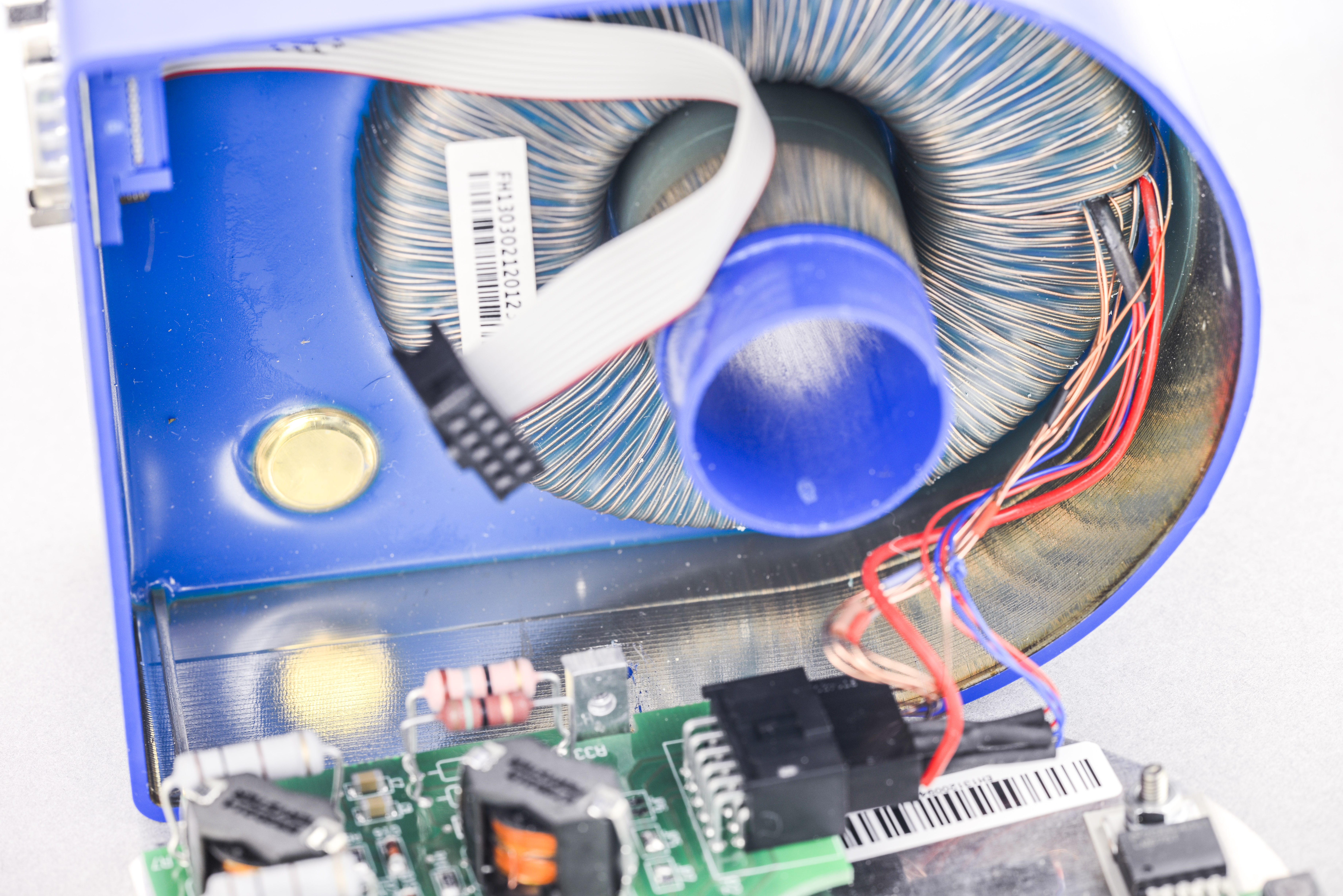
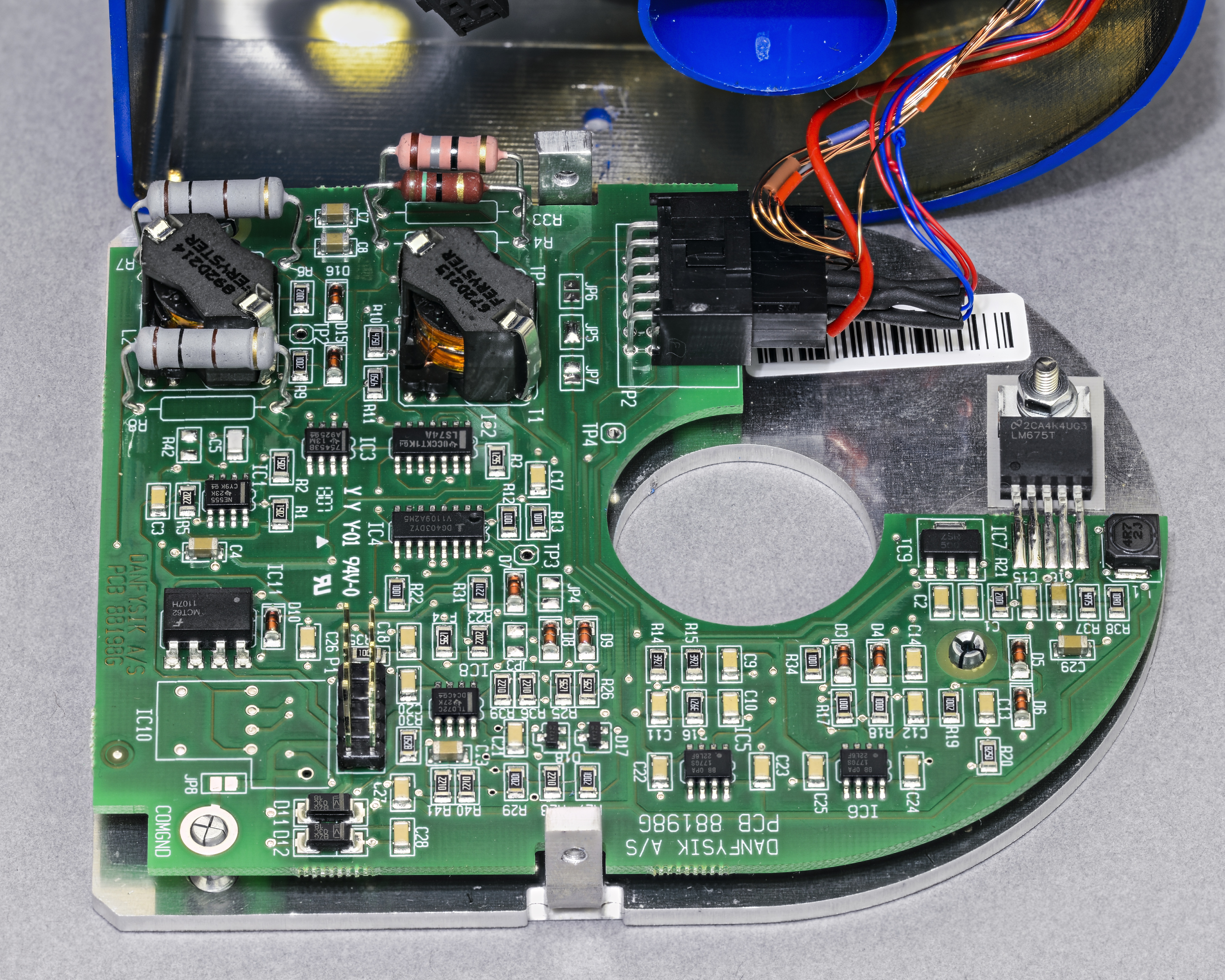
Face with label is solid aluminum plate used for heatsinking as well, as you can see after removing two screws. Coil is embedded in casing with single mold.

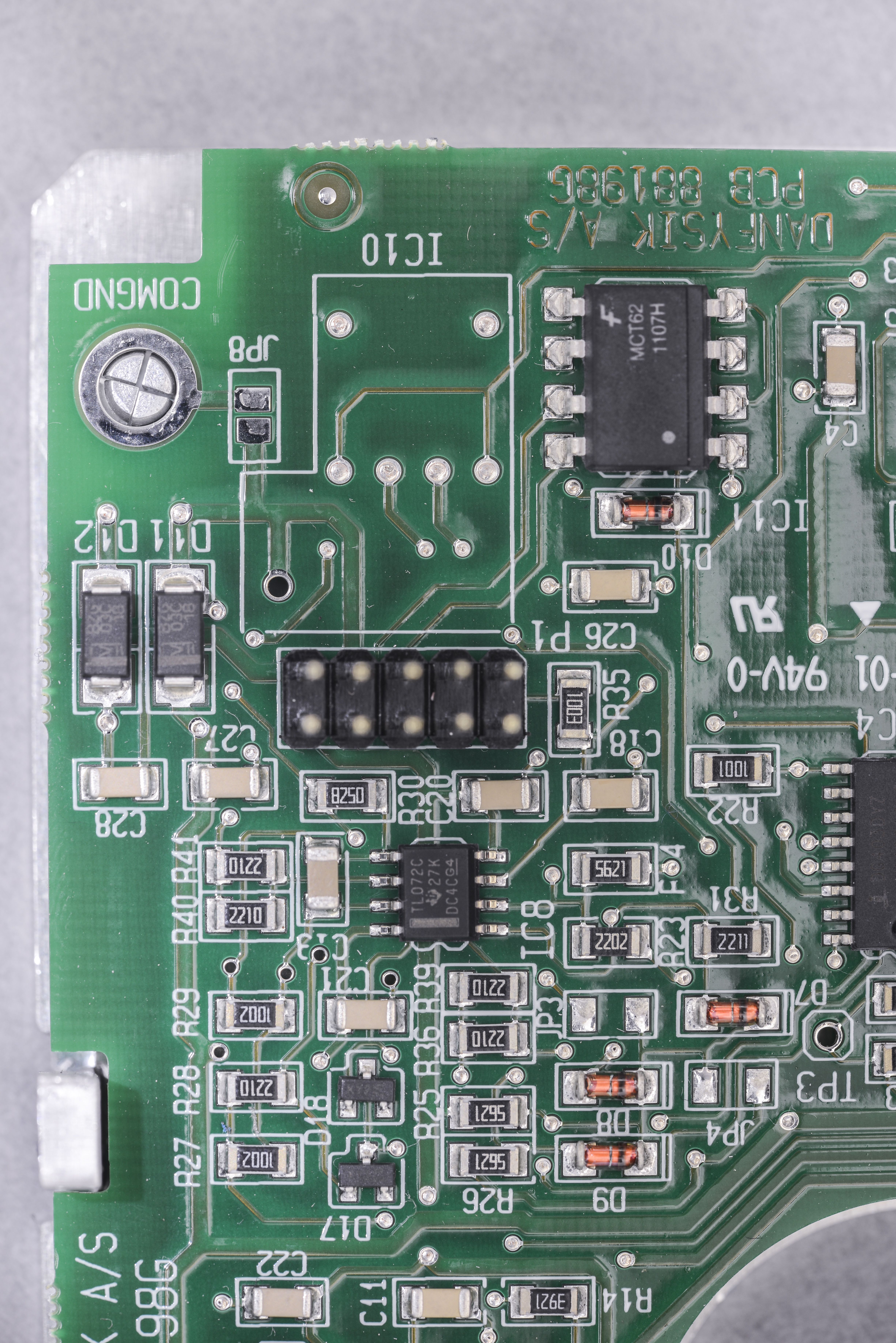
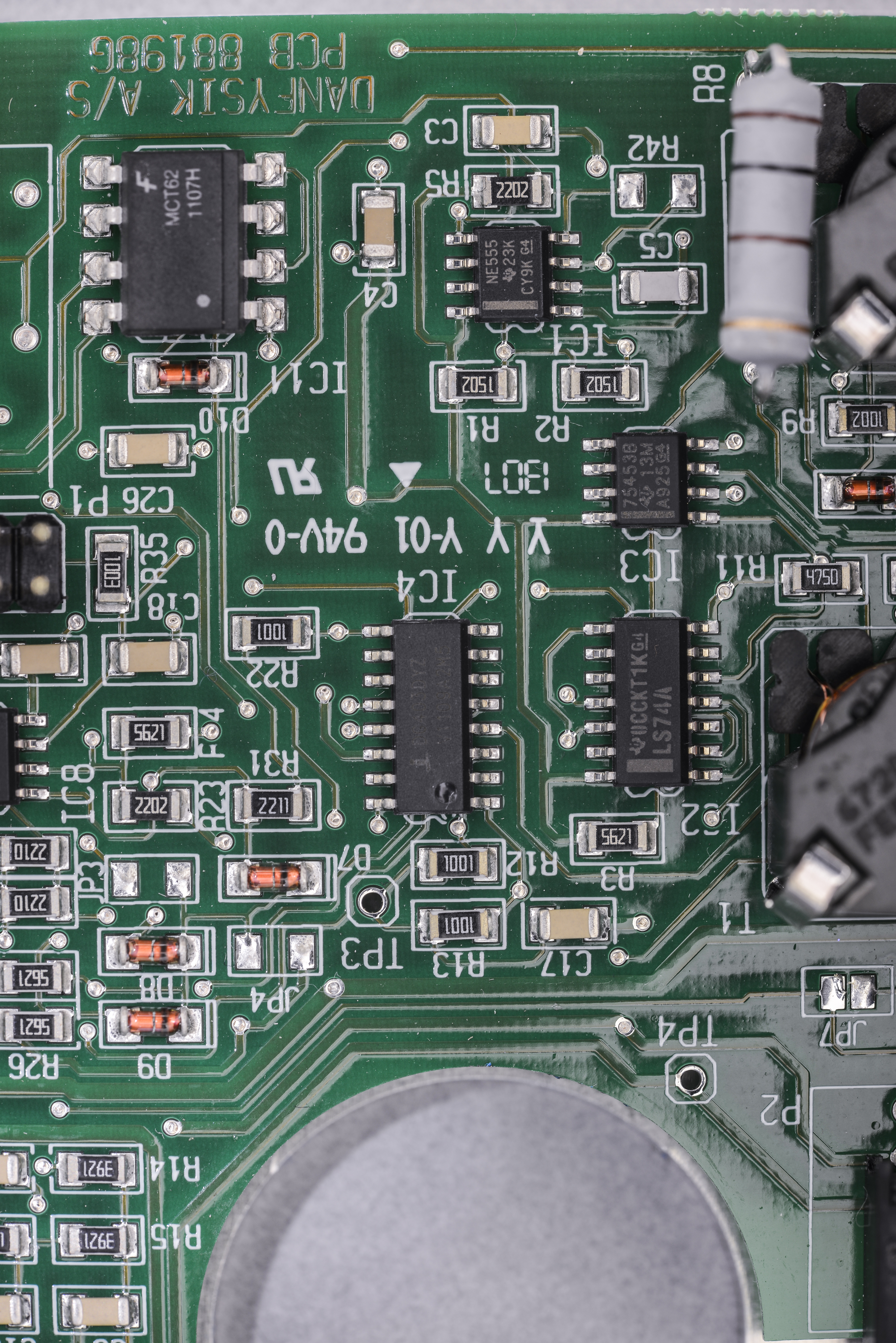
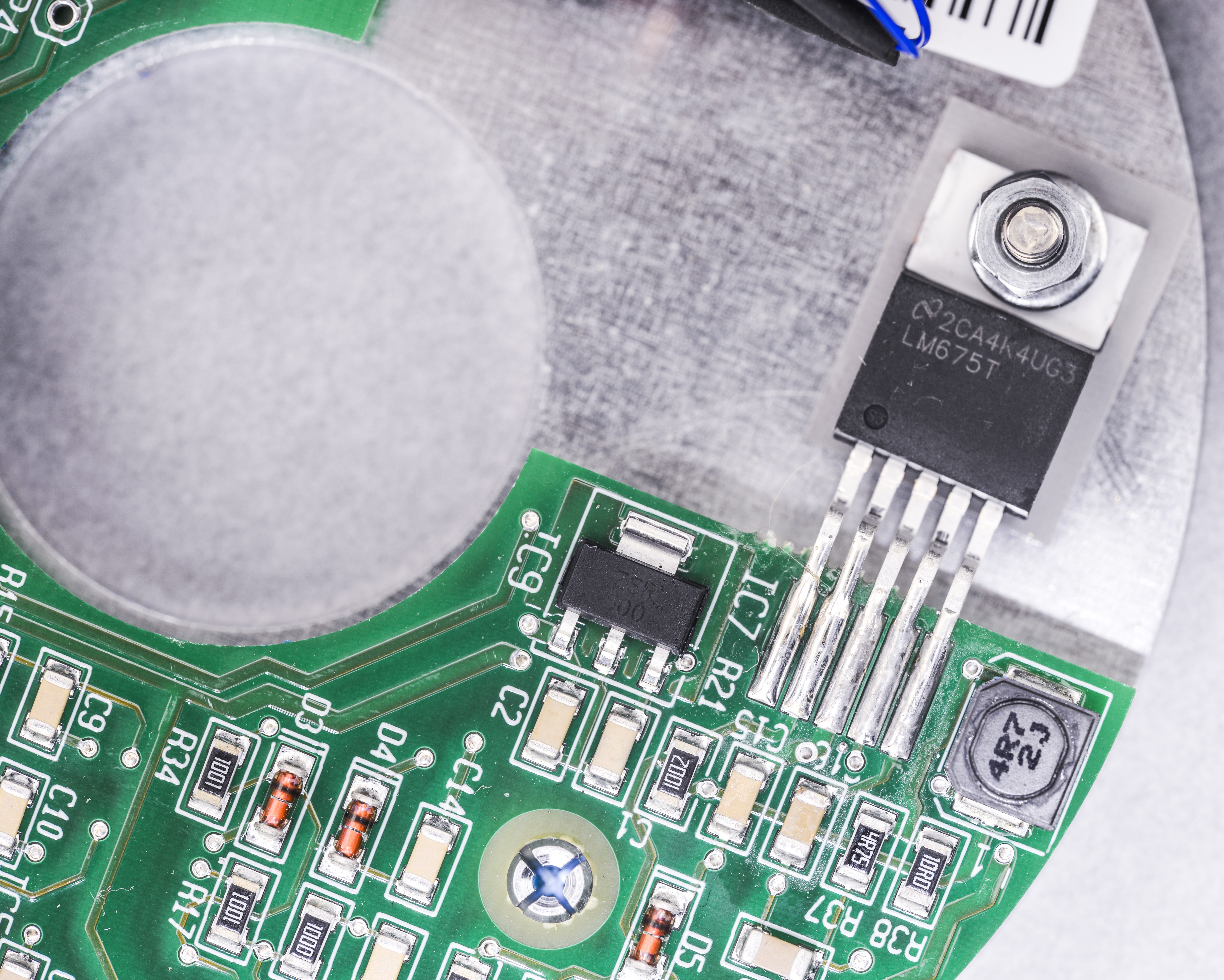
As you can see this current sensor technology using some fair amount of electronics to do it’s magic. PCB still have marking from DANFYSIC.
LEM has acquired the transducer Danfysik Advanced Current Products (ACP) A/S with in 2008. DANFYSIC is based near Copenhagen, Denmark, and still in business for high-power application.
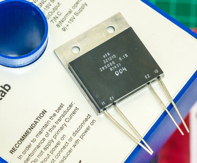
As accuracy and tempco would depend on secondary burden resistor, I chose not to compromise on this and got these custom 74$/piece CSNG Foil from Vishay Precision Group. Yes, you can buy them in single piece quantity. I heard these are same type resistors as used in LHC magnet control systems.
Performance quick check
One of sensors was tested with very stable current source, such as Fluke 5700A high performance multi-function calibrator.
Current source 1: Fluke 5700A
Current source 2: Fluke 5700A + 5205A
Configuration : 7 turns thru LEM
Burden shunt: 2.5 Ω Vishay PG foil 1ppm/C 9W, CSNG
Meter: Keithley 2002 on 200mV range
All gear was freshly calibrated and kept within 2 °C of cal temp.
| Current sourced from MFC | Measured voltage on burden resistor |
|---|---|
| 0A | 0 mVDC, nulled |
| 214.1942 µA | 0.00250 mV |
| 2.141942 mA | 0.02505 mV |
| 21.41942 mA | 0.249960 mV |
| 200mA | 2.33431 mV |
| 214.1942mA | 2.49986 mV |
| 1A | 11.6719 mV |
| 2A | 23.3434 mV |
| 2.141942A | 25.00005 mV |
High current tests with Fluke 5220A amplifier (uncalibrated) + 5700A (calibrated)
| Current sourced from MFC + AMP | Measured voltage on burden resistor |
|---|---|
| 1.000000 V(MFC) | 11.64732 mV |
| 2.000000 V(MFC) | 23.31058 mV |
| 2.142857 V(MFC) | 24.98688 mV |
| 3.000000 V | 34.99193 mV |
| 4.000000 V | 46.66403 mV |
| 5.000000 V | 58.33468 mV |
| 6.000000 V | 70.00847 mV |
| 7.000000 V | 81.68046 mV |
| 8.000000 V | 93.35251 mV |
| 9.000000 V | 105.024558 mV |
| 10.000000 V | 116.69671 mV |
| 11.000000 V | 128.36888 mV |
| 12.000000 V | 140.04104 mV |
| 13.000000 V | 151.71314 mV |
| 14.000000 V | 163.37437 mV |
| 15.000000 V | 175.05746 mV |
| 16.000000 V | 186.72914 mV |
| 16.300000 V | 190.23057 mV |
5220A could not go higher, as it’s not suitable for large inductive loads and was losing stability after 16A.
Will use these current sensors in further experiments later on, to check their performance. If you interested, feel free to join in comments.
Modified: Jan. 30, 2019, 4:59 p.m.