Contents
Introduction
Dimensional metrology is the science of measuring physical dimensions, such as length, width, height, and depth. It is a foundation of all industries working with physical objects, from building a house in the woods to nanotechnology making chips in your computer device. In dimensional metrology, the concept of a “unit of measurement” is essentially representation of the fundamental unit of length metre in the International System of Units.
The definition of the metre has evolved over time as technology has advanced, from a physical artifact like a precious metal bar to a precise, reproducible standard based on the speed of light. Today, the meter is defined as the distance that light travels in a vacuum during a specific time interval. This precise and universal definition ensures consistency and accuracy in measurements across the world, enabling the development of technologies and industries that depend on reliable and standardized length measurements.
As a practical result, the optical systems stands at the forefront of precision measurement of length, offering unparalleled accuracy in scientific and industrial applications. Optical interferometer experiment proven existance of gravitational waves in LIGO project. Utilizing the principles of laser interferometry, such system measures tiny displacements, vibrations, and changes in position with exceptional resolution. This article explores such system using old HP/Agilent components and their underlying technology, applications to see how it is practically possible to make precise dimensional measurements, if all the components are functioning properly. Samuel M. Goldwasser built a legendary source of information and knowledge about such systems on his website.
Disclaimer
Redistribution and use of this article or any files referenced in it, in source and binary forms, with or without modification, are permitted provided that the following conditions are met:
- Redistribution of article must retain the above copyright notice, this list of conditions, link to this page (https://xdevs.com/article/hpi/) and the following disclaimer.
- Redistribution of files in binary form must reproduce the above copyright notice, this list of conditions, link to this page (https://xdevs.com/article/hpi/), and the following disclaimer in the documentation and/or other materials provided with the distribution, for example Readme file.
All information posted here is hosted just for education purposes and provided AS IS. In no event shall the author, xDevs.com site, or any other 3rd party, including HP/Agilent/Keysight be liable for any special, direct, indirect, or consequential damages or any damages whatsoever resulting from loss of use, data or profits, whether in an action of contract, negligence or other action, arising out of or in connection with the use or performance of information published here.
If you willing to contribute or add your experience regarding any test instruments or provide any extra information, such as firmware dumps, internal photographs, you can do so following these simple instructions
Manuals and articles
System design and principle of operation
Laser Interferometer is a precision measurement system designed for accurate displacement measurements, commonly used in machine tool calibration and dimensional metrology. Its setup consists of several key components arranged to form a stable optical measurement path.
At the core of the system is the laser head, which generates a highly stable, frequency-controlled laser beam. This beam is emitted toward a set of optical components, typically including beam splitters, interferometers, and retroreflectors. The laser beam is split into reference and measurement paths, allowing displacement to be determined by comparing the phase difference between the two beams. It’s possible to use one beam with different frequency or properties to obtain interference with same optical path as well.
The interferometer optics is usually mounted on a fixed reference point, while the retroreflector (or mirror) is attached to the moving axis of the machine or object being measured. As the machine axis moves, the retroreflector returns the measurement beam back through the interferometer. Any change in position causes a shift in the interference pattern, which is directly proportional to the displacement.
Environmental factors such as air temperature, pressure, and humidity can affect laser wavelength. To maintain accuracy, the source in such systems is typically integrated with environmental compensation sensors, which automatically correct measurements based on environment conditions. The measured signals are processed by the measurement electronics and software, which convert the optical interference data into precise linear or angular displacement values. The system can be configured for different measurement modes, including linear positioning, straightness, flatness, and angular errors, depending on the optical setup used.
All this concept is not new and been achieved and built by A.A. Michelson in year 1887. Two frequency laser based systems were commercialized by Hewlett-Packard in 1970’s with a 5525A system.
Here’s a description of the HP/Agilent interferometer system components that I’ve aquired from friend Mike for this article.
Main source (Two-Frequency HeNe Laser)
This is the heart of the interferometer, providing the very stable two-frequency optical beam necessary for displacement measurement. Typical HP interferometer setups use variants in the 5517 and 5519 series of laser heads. Head I’ve acquired is a 5517B variant with serial number 2451B010301, manufactured on 14th December 1989 by 02877 :).
Front aperture where light comes out is equipped with a simple mechnical gate. This contunous-wave laser helium-neon gas laser generate very stable Zeeman-split emission with nominal frequency 473.61254 THz with output power under 1 mW which puts it in Class II safety laser product.
Based on sticker at the back this unit was probably recalibrated/readjusted by Agilent under new serial number US44100443 with calibrated power 248 µW and Zeeman split frequency 2.24 MHz in December 2004.
Sam’s Laser FAQ is amazing dive into all the various lasers that HP and Agilent made for use in such measurement systems. I can only contribute with my own high-resolution photograph captured with my revived GFX 100 II Poseidon camera

Rear has four status LED inficators to show power supplies condition and laser status.
The only electrical interface on laser head is large mil-style circular port with 18 pins. Each pin has letter designator with clear marking.
Pinout of the signals for my 5517B head is presented in table below.
| Pin letter | Designator | Purpose/connection |
|---|---|---|
| A | No Connection on 5517 | |
| B | ~MEAS (Not used on 5517) | No connection |
| C | MEAS | Measurement path signal |
| D | Signal Return (MEAS) | Return for pins B and C |
| E | ~REF | Differential to F |
| F | REF | Zeeman beat signal from internal optical sensor |
| G | Ground | Power ground |
| H | Ground | Power ground |
| J | +15 VDC Sense | Positive supply sense |
| K | +15 VDC | Positive supply |
| L | -15 VDC | Negative supply |
| M | +15 VDC | Positive supply |
| N | Cable Shield | Shielding braid |
| P | Cable Shield | Shielding braid |
| R | Signal Return (REF) | Return for pins E and F |
| S | Ground | Power ground |
| T | +15 VDC | Positive supply |
| U | Cable Shield | Shielding |
Mating connector for this interface is PT06A-14-18PX.
Receiver

Front has bit dirty optics window but no other mechanical features.

On the back we get power pin/connector (?) and four pin circular bayounet connector somewhat similar to LEMO 1S series with both genders. I’ve got matching piece of cable to couple with this connector. If anyone knows this particular model/manufacturer for this connector please let me know.
Detect interferometer output signals and interface with measurement electronics/software:
HP Receivers (various models depending on axis and system configuration).
Measurement counters, interface boards, and conversion electronics (e.g., HP-IB, PCI, compensation boards).
repairfaq.org
Digitizer/electronics
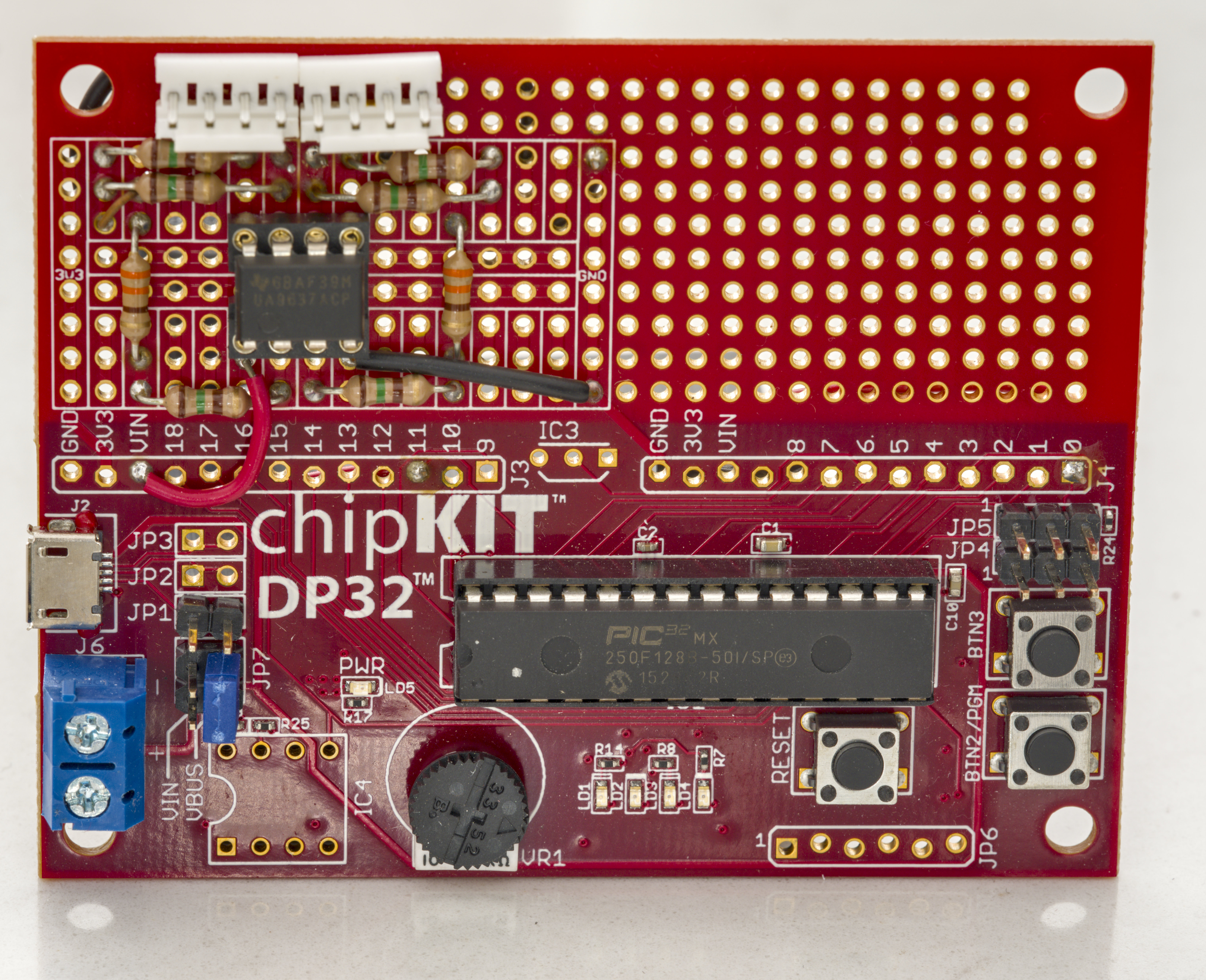
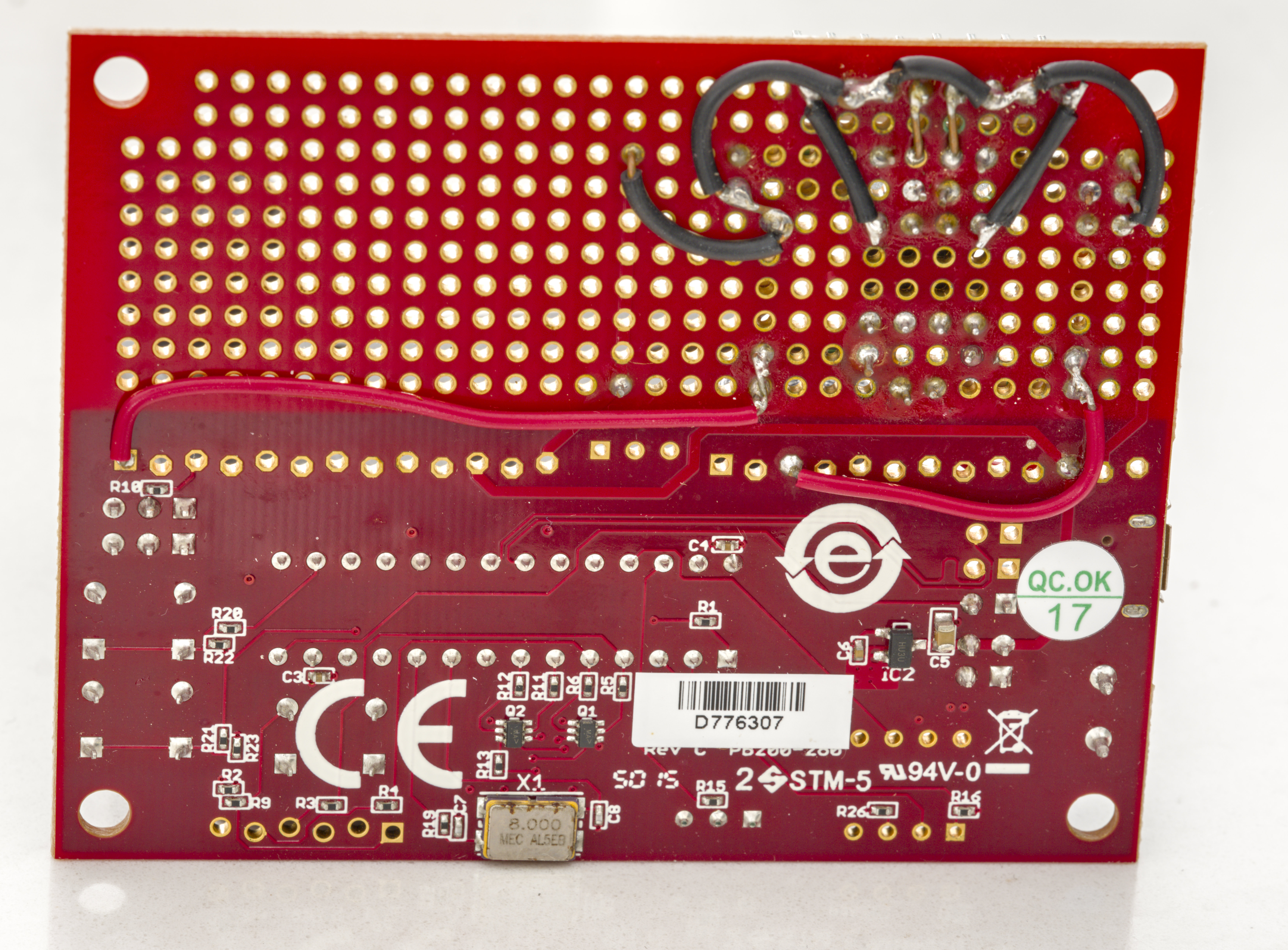
Originally such HP systems used dedicated HP display/monitor instrument which is bulky, expensive and rare to find on secondary market. Instead of that I’ve acquired modern electronic kit that Sam and Jan made, called uMD-1. It is older electronics built reusing chipKIT DP32 Arduino board.
2. Beam Splitters
Create the reference and measurement beams from the laser output:
HP 10700A 33% Beam Splitter
HP 10701A 50% Beam Splitter
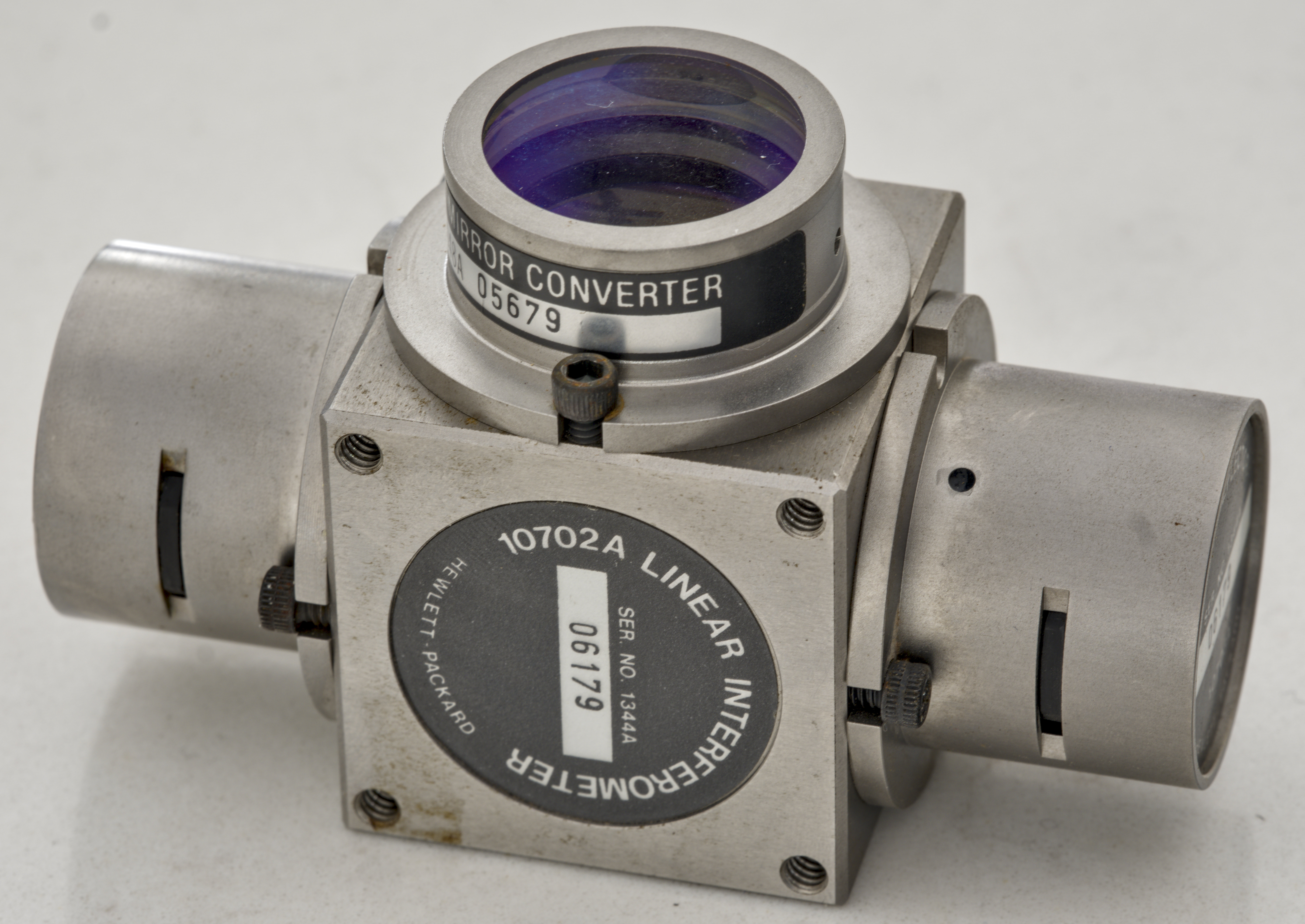
Interferometer Optics
These include the beams and reference path optics that comprise the actual interferometer assemblies:
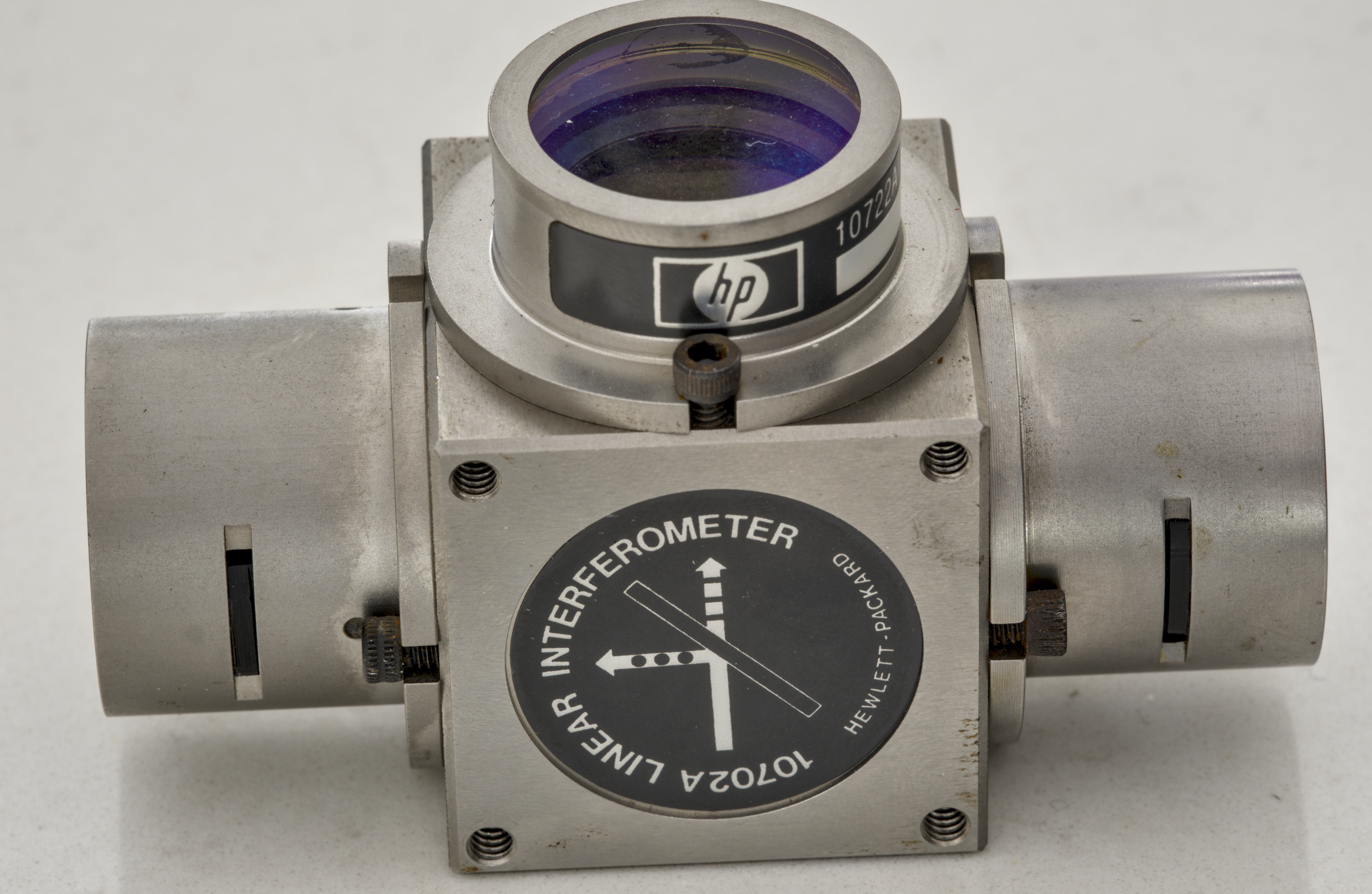
HP 10702A Linear Interferometer – linear displacement measurement optics.

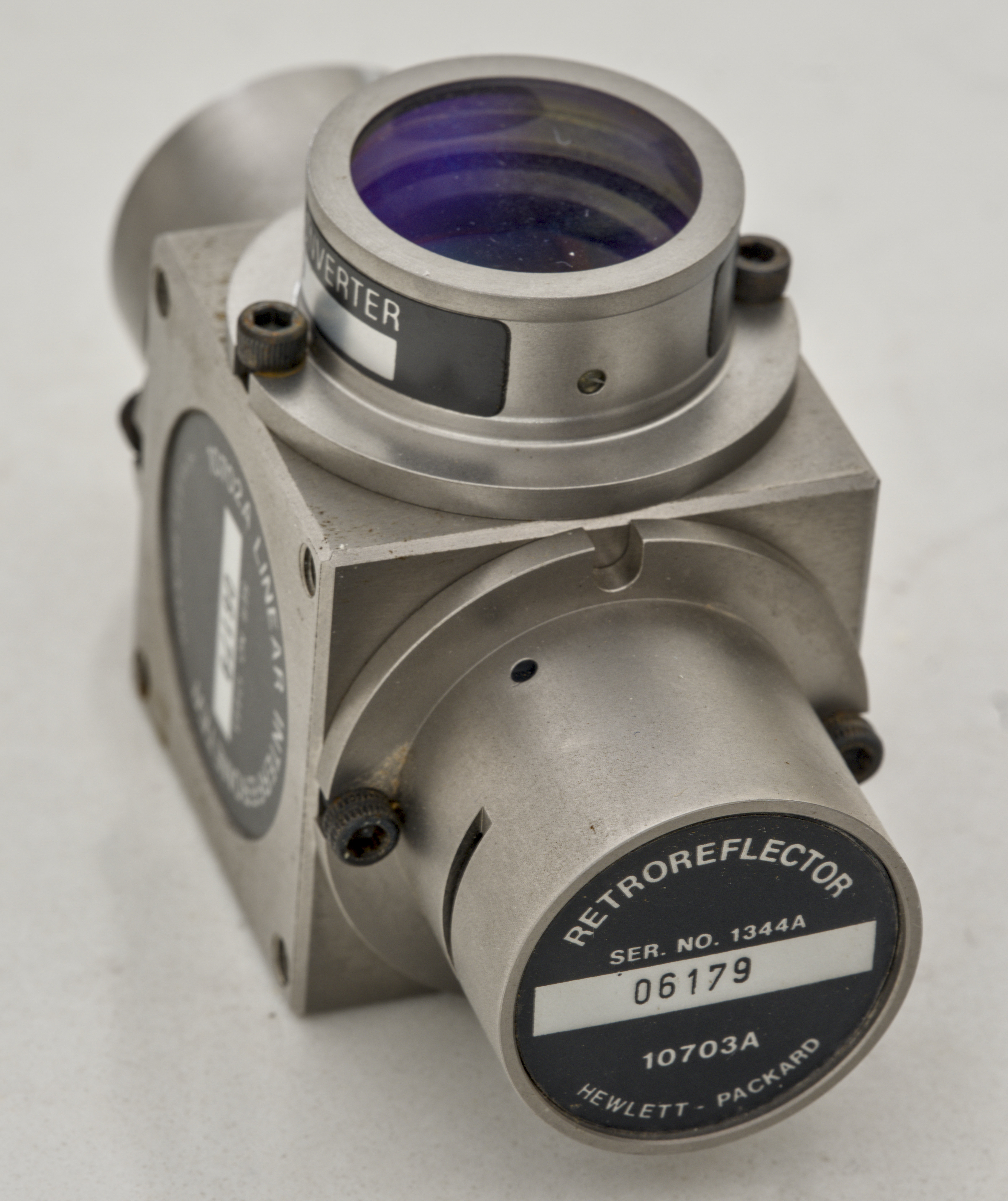
Interferometer cube came with two mounted HP 10703A Retroreflectors as primary retroreflectors.
There is also 10722A plane mirror unit on the forward path.
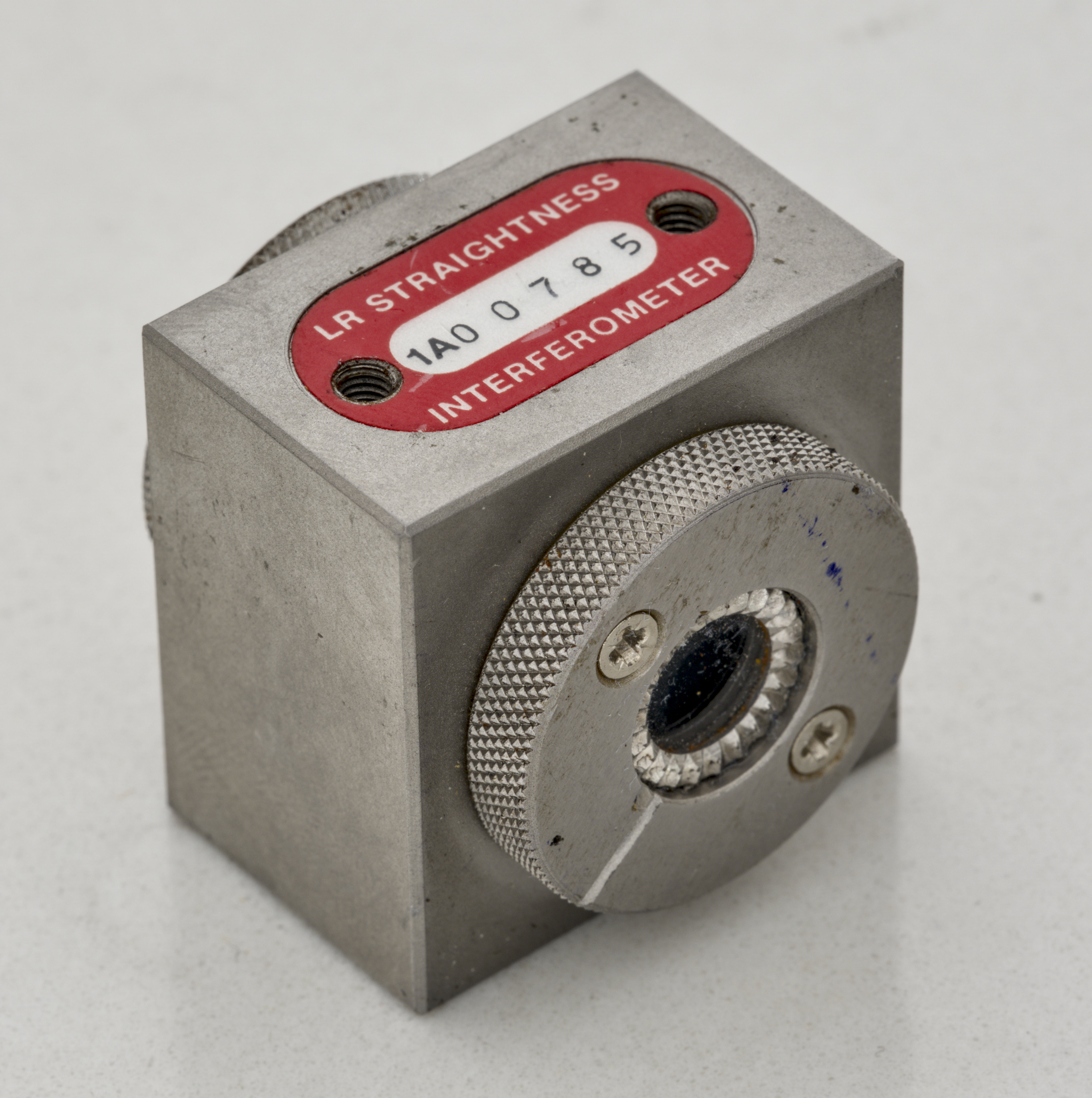
There is also second interferometer cube similar to HP 10702A but made by Excel, model 1012A.
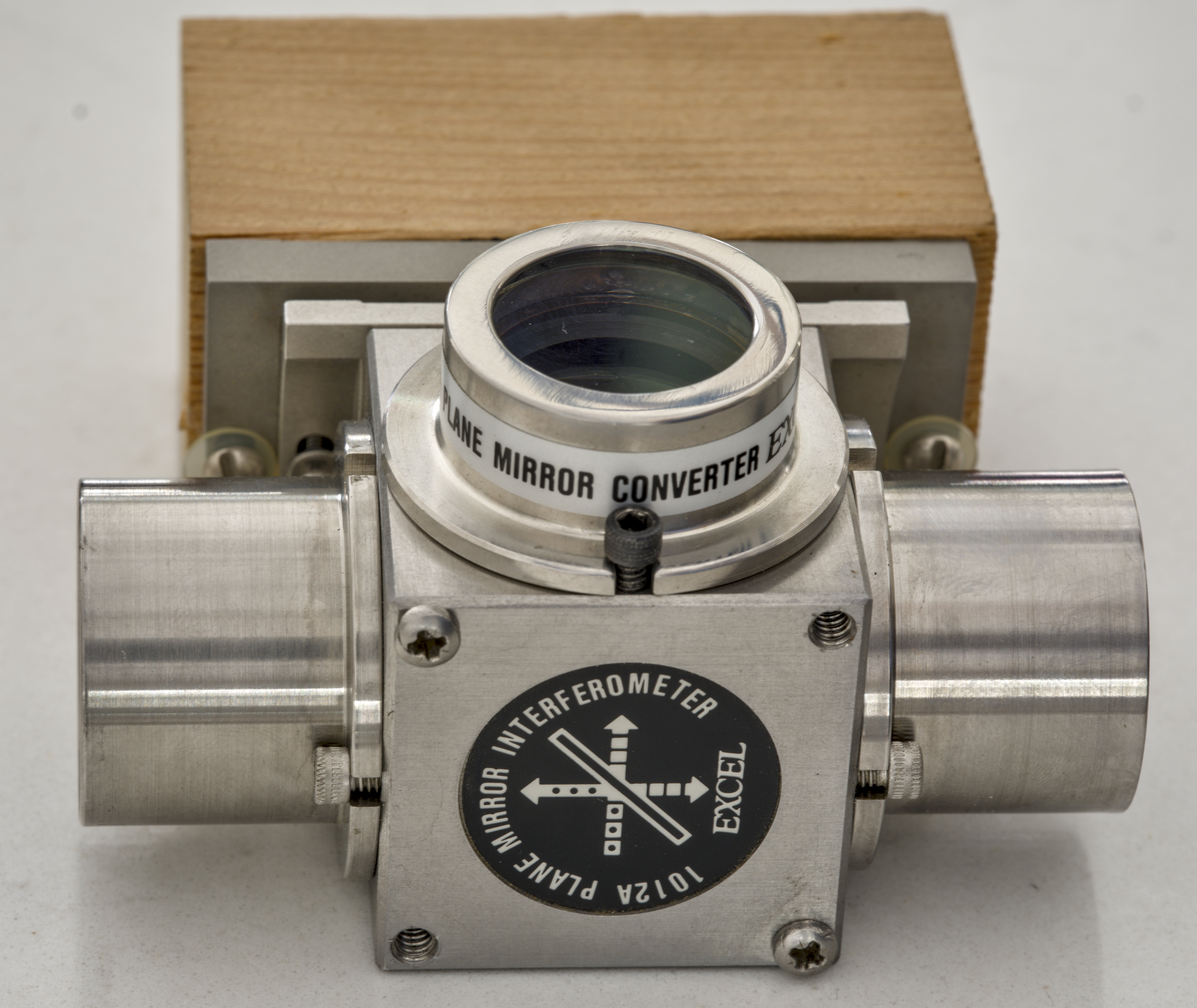
It’s physically very similar to 10702A above, but mounted on a tiltable plate and wooden block :)
Retroreflectors for reference and measurement paths are model 1013A also made by Excel.
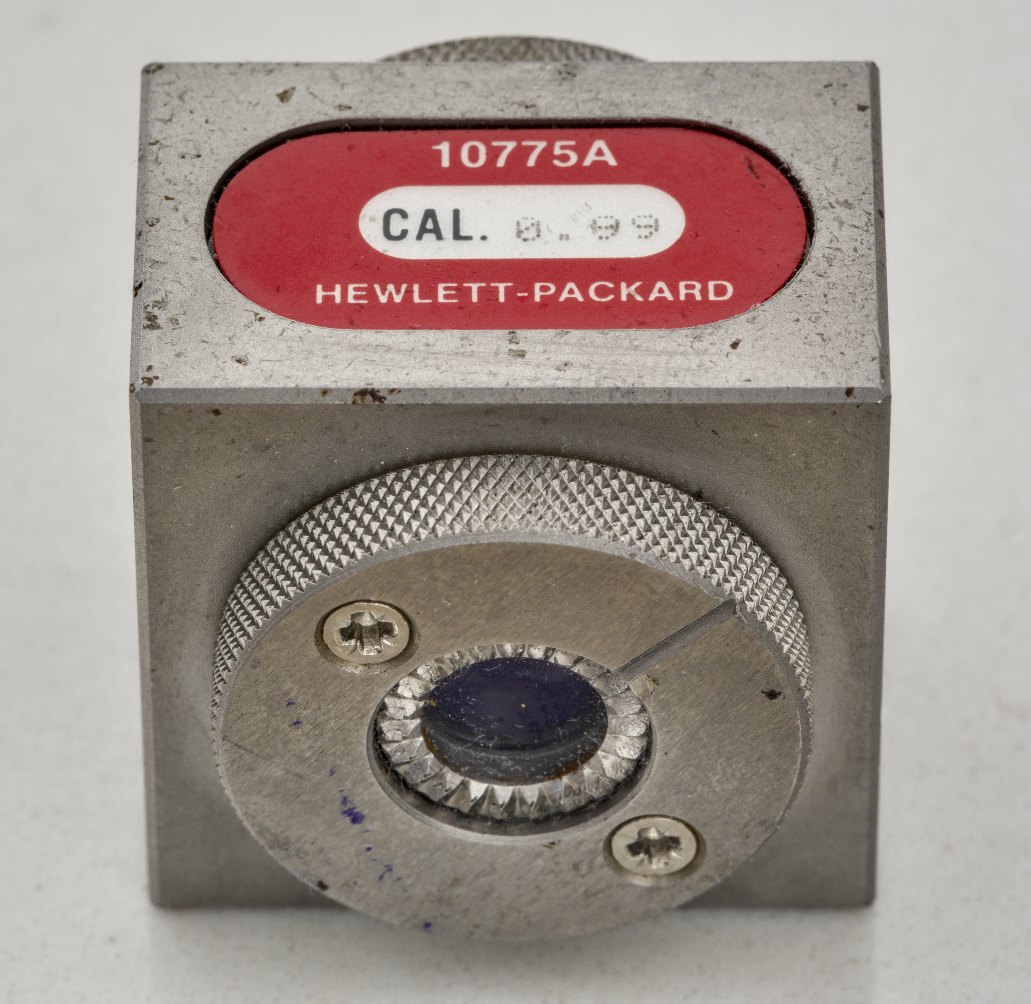
Beam Benders & Alignment Aids
HP 10707A 90 degree Beam Bender – for routing beams in compact setups. I have three of these bender cubes.
Partial teardown of the laser head

Conclusion
Projects like this are born from passion and a desire to share how things work. Education is the foundation of a healthy society - especially important in today's volatile world. xDevs began as a personal project notepad in Kherson, Ukraine back in 2008 and has grown with support of passionate readers just like you. There are no (and never will be) any ads, sponsors or shareholders behind xDevs.com, just a commitment to inspire and help learning. If you are in a position to help others like us, please consider supporting xDevs.com’s home-country Ukraine in its defense of freedom to speak, freedom to live in peace and freedom to choose their way. You can use official site to support Ukraine – United24 or Help99. Every cent counts.
Modified: Dec. 20, 2025, 10:43 p.m.