Contents
- Intro
- Model 2510 internals
- Repair
- Performance check and calibration
- Failure on TEC LO+ Force pin
- Other user’s units
- Options and extras
Intro
TEC is a semiconductor module working based on Peltier thermoelectric effect principle, which is basically describing forces heat transfer effects by using electrical P-N junctions from cold side to hot side.
This Keithley SMU is capable of directly controlling 10V@5A TEC element, to a specific temperature set-point. MSRP for Model 2510 is around US$4380, so it’s definitely not a average hobbyist lab gear spectrum, but rather a professional application tool.
Main features of TEC SouceMeter are:
- 50W TEC Controller combined with DC measurement functions
- Fully digital P-I-D control
- Designed to control temperature during laser diode module testing
- Wide temperature setpoint range (-50°C to +225°C) and high setpoint resolution (±0.001°C) and stability (±0.005°C)
- Compatible with a variety of temperature sensor inputs like thermistors, RTDs, and IC sensors
- Maintains constant temperature, current, voltage, and sensor resistance
- AC Ωs measurement function verifies integrity of TEC
- Measures and displays TEC parameters during the control cycle
- 4-wire open/short lead detection for thermal feedback element
- IEEE-488 and RS-232 interfaces
- Compact, half-rack design
Here is project tracker as usual when doing repairs, to keep things up to date.
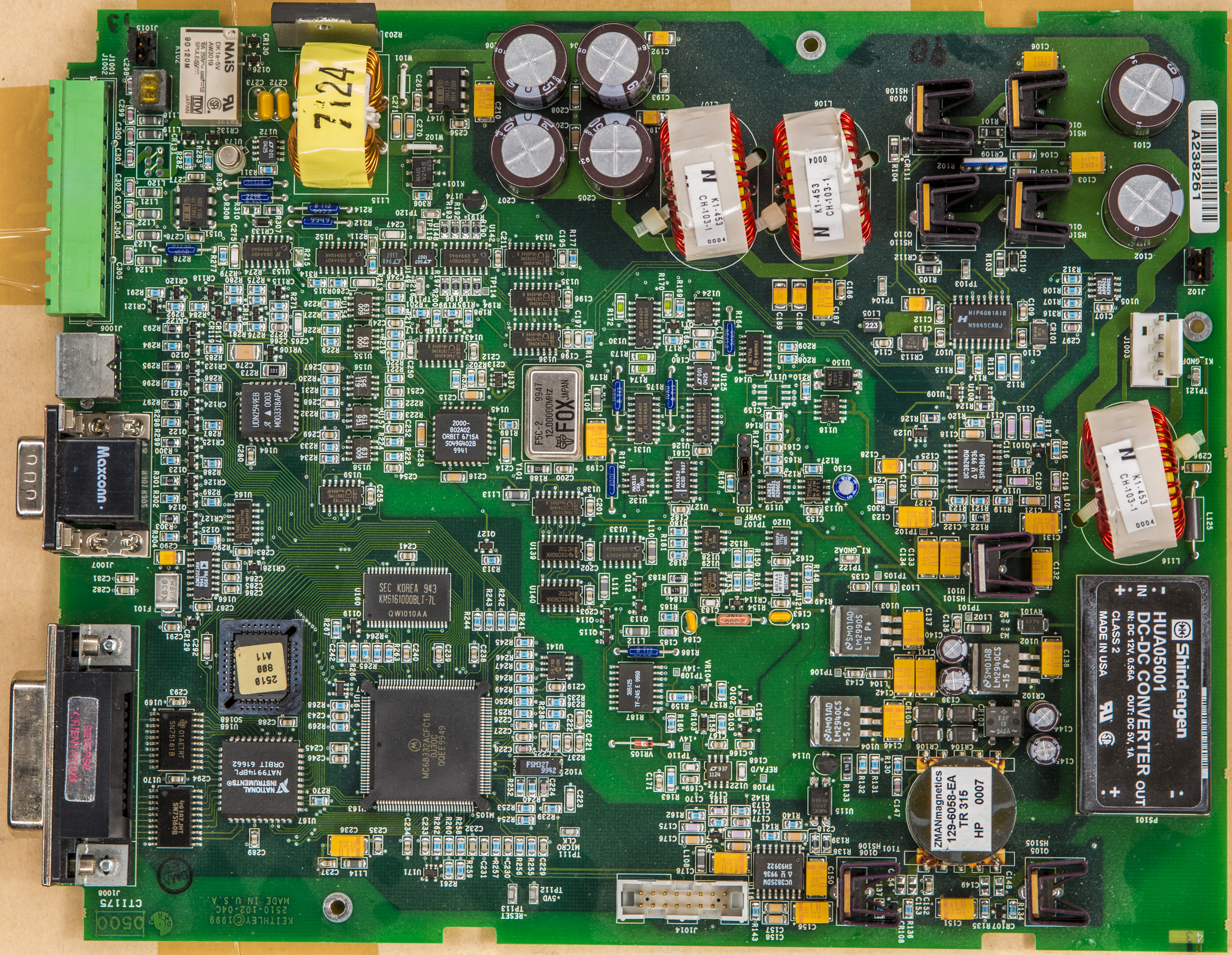
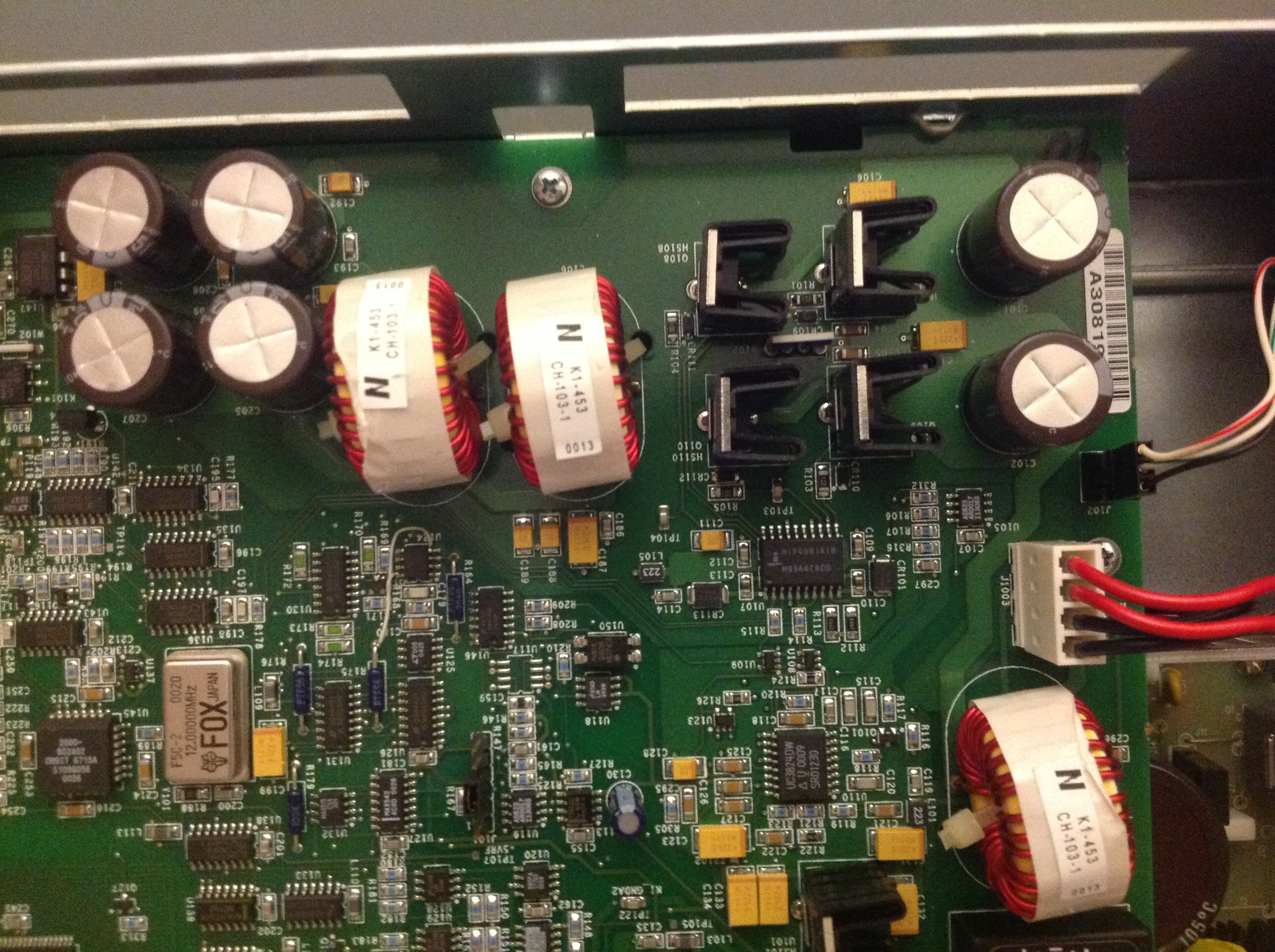
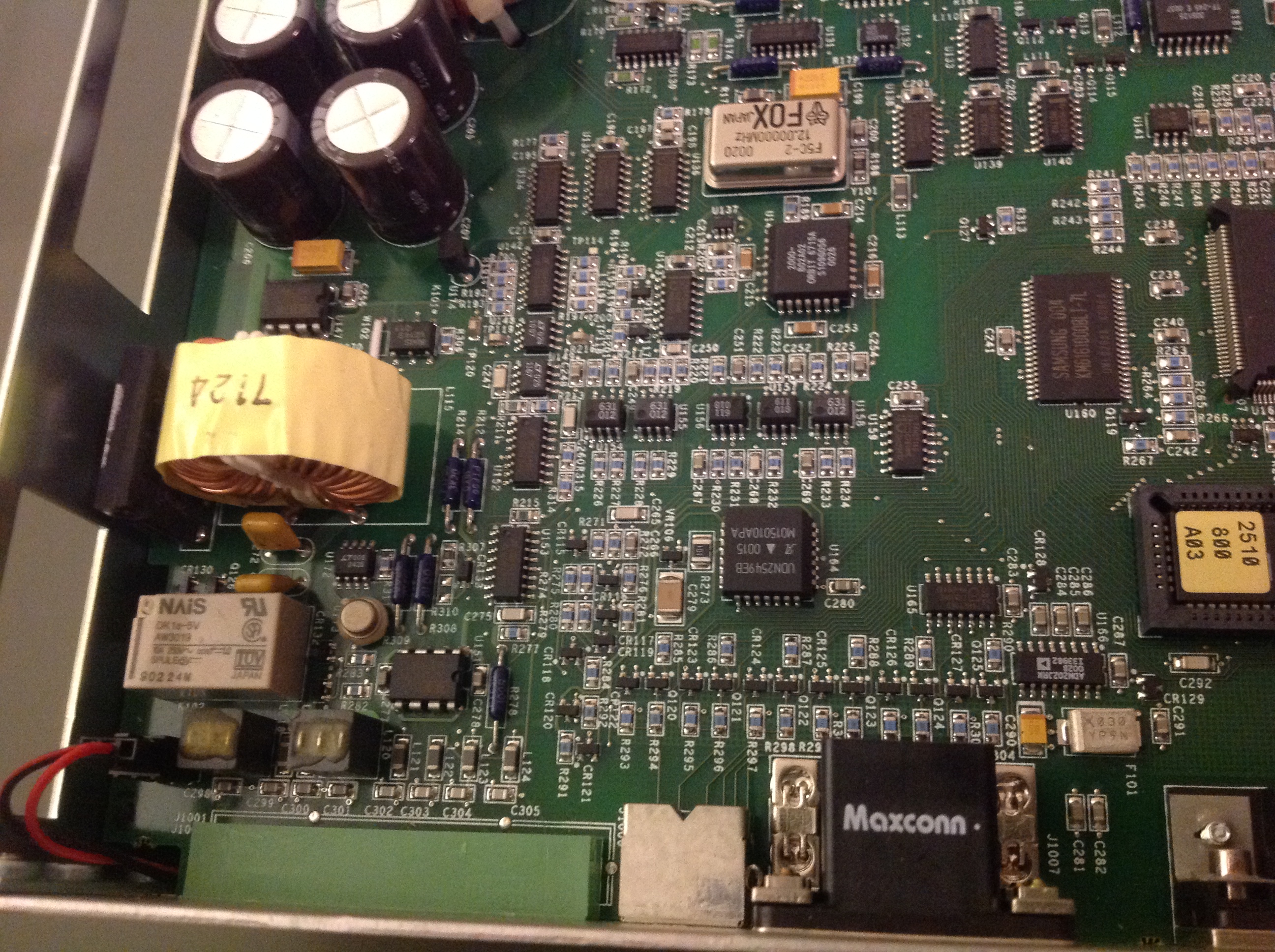
Model 2510 internals
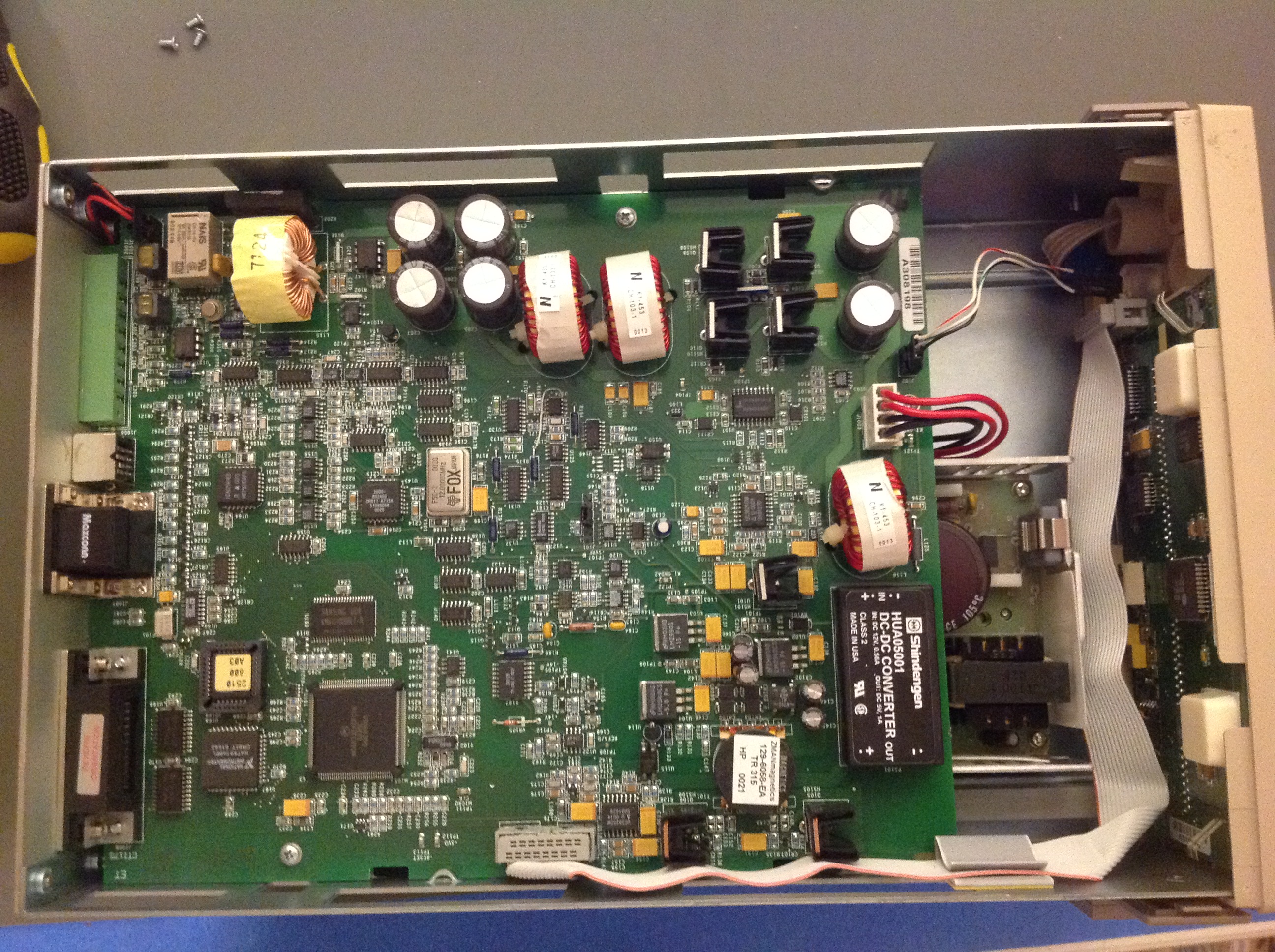
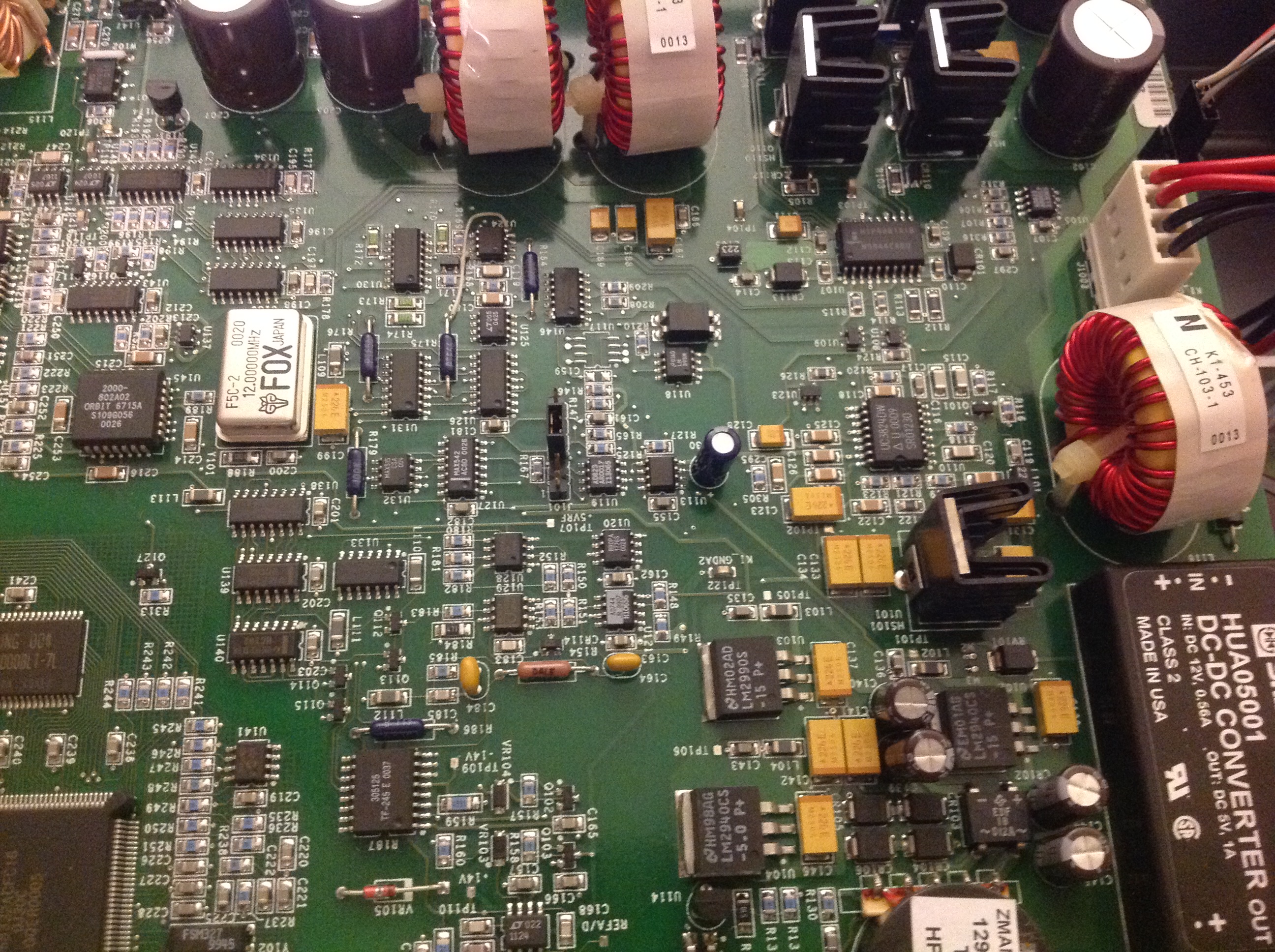
Overview on mainboard:
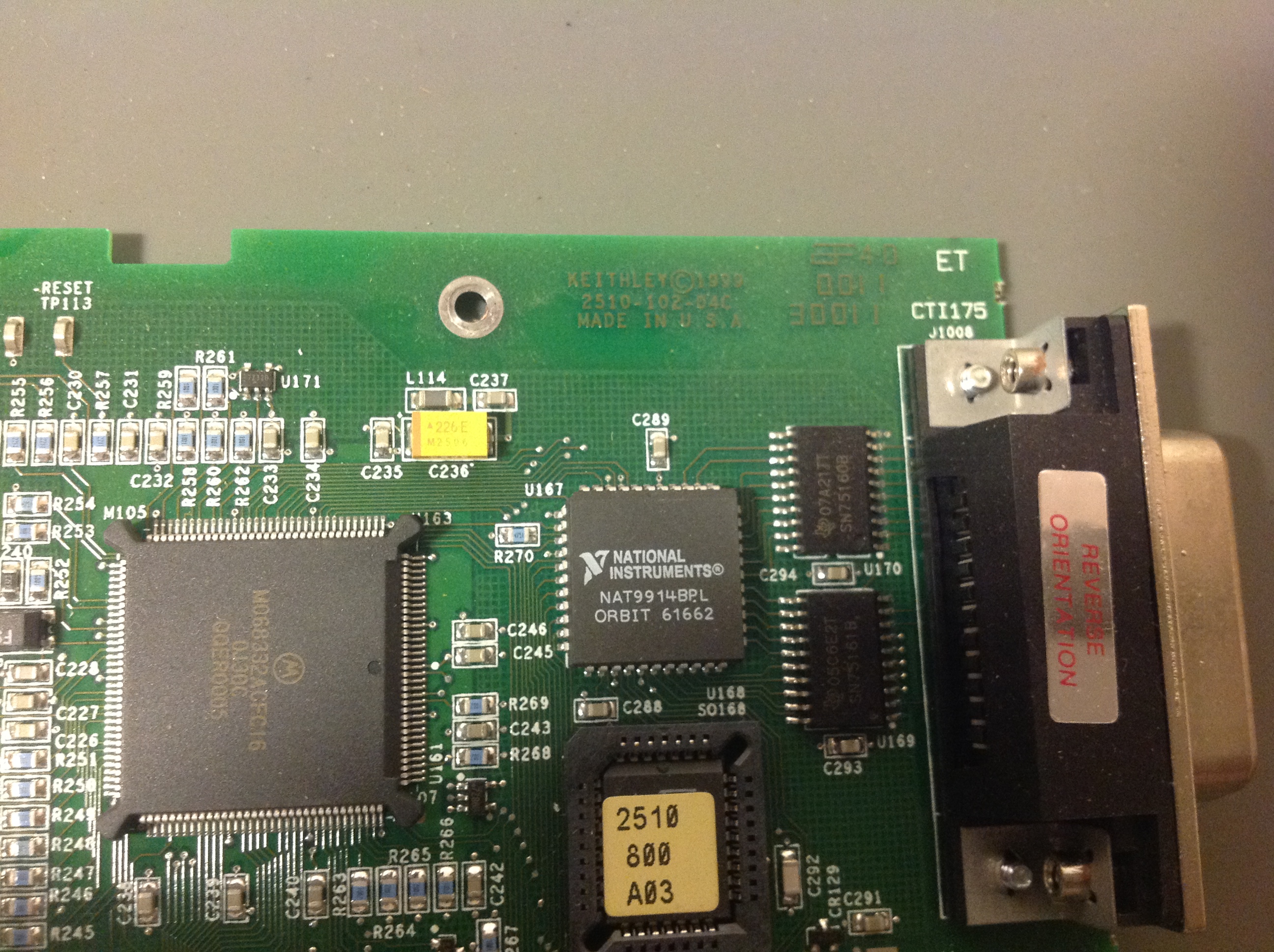
GPIB and firmware flash chip (ATMEL AT49F040).
Isolation and digital I/O
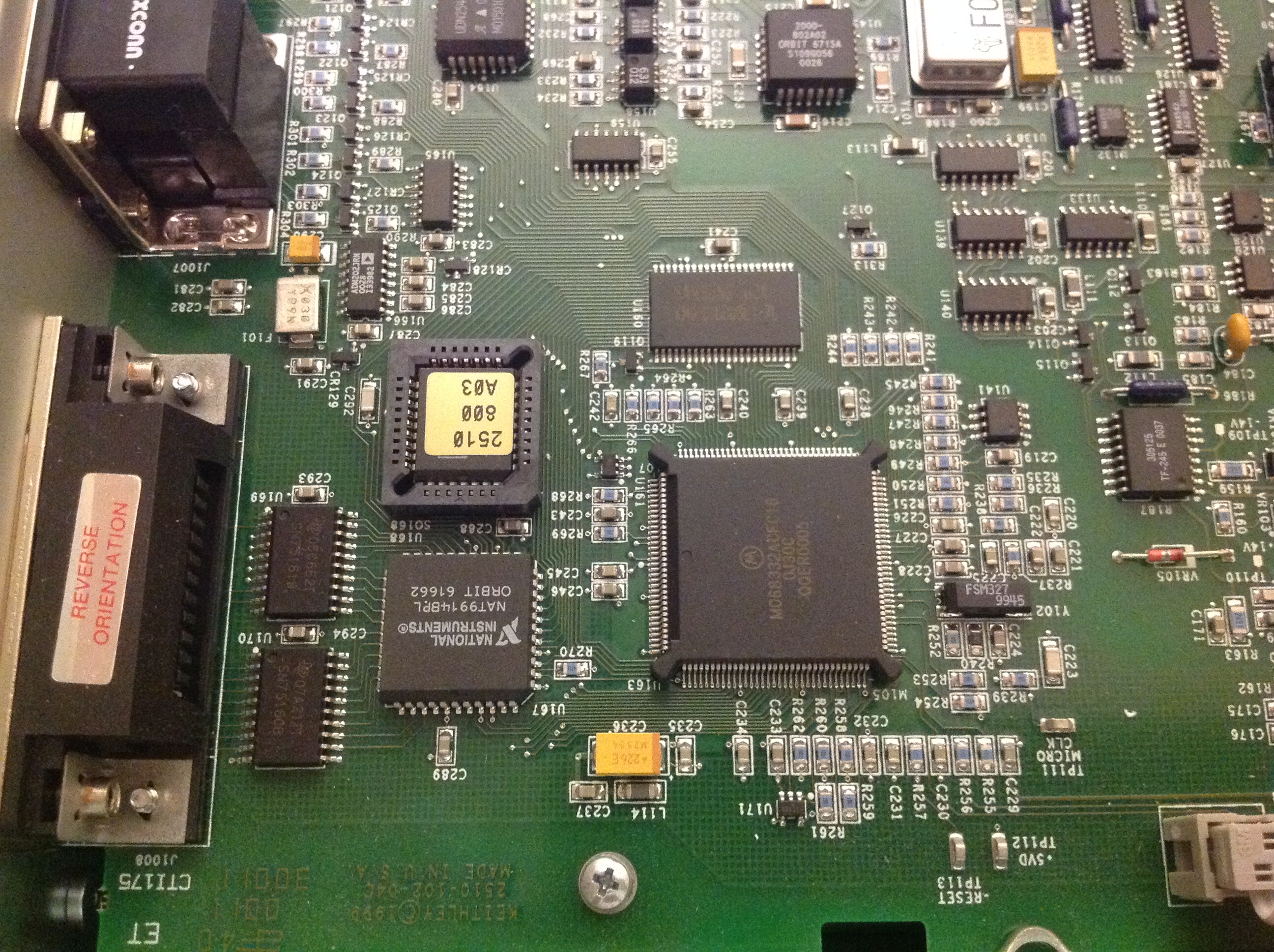
Output connector and circuitry around it. According to service manual, U172 is voltage reference. Anyone knows what that part is?
Multislope custom ADC chip leveraged from Keithley 2000.
CPU and SRAM

Infamous TF-245 resistor network, same as Keithley 2000. Some analog stuff around..

Voltage regulator circuits and front panel connector.
Voltage regs switcher
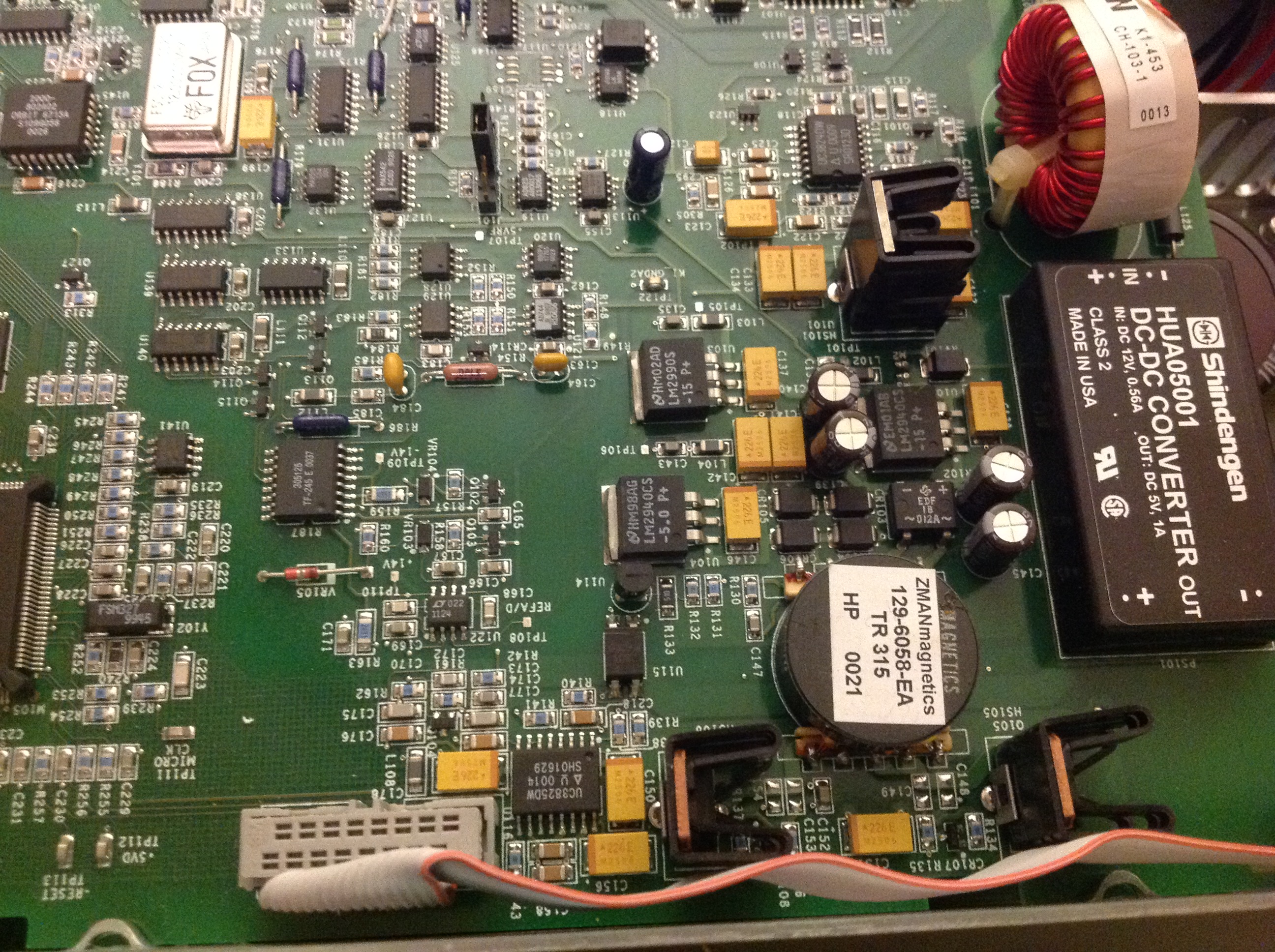
LDO’s for +15. -15 and 5V.
Another switcher.
Amp controller
Voltage reference (U125), some PTF56 resistors and analog circuits.
More output circuitry..
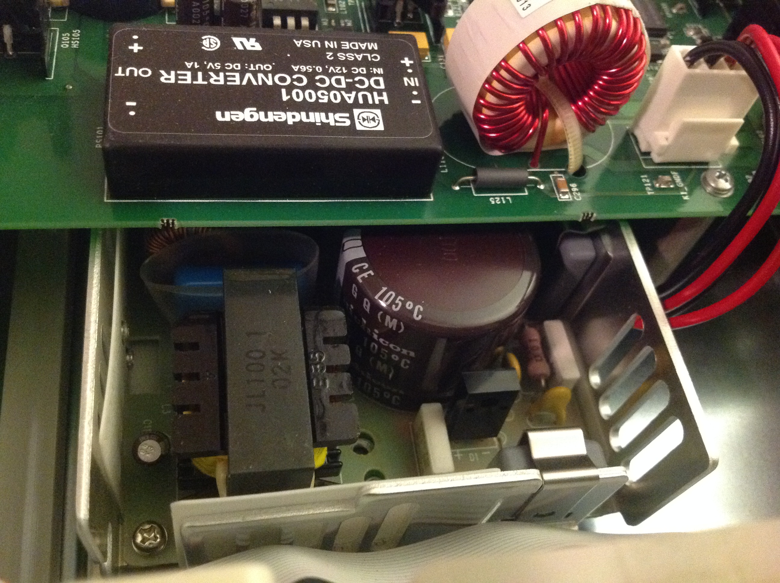
DC-DC taking +15V from mains AC/DC and downconverting into +5V
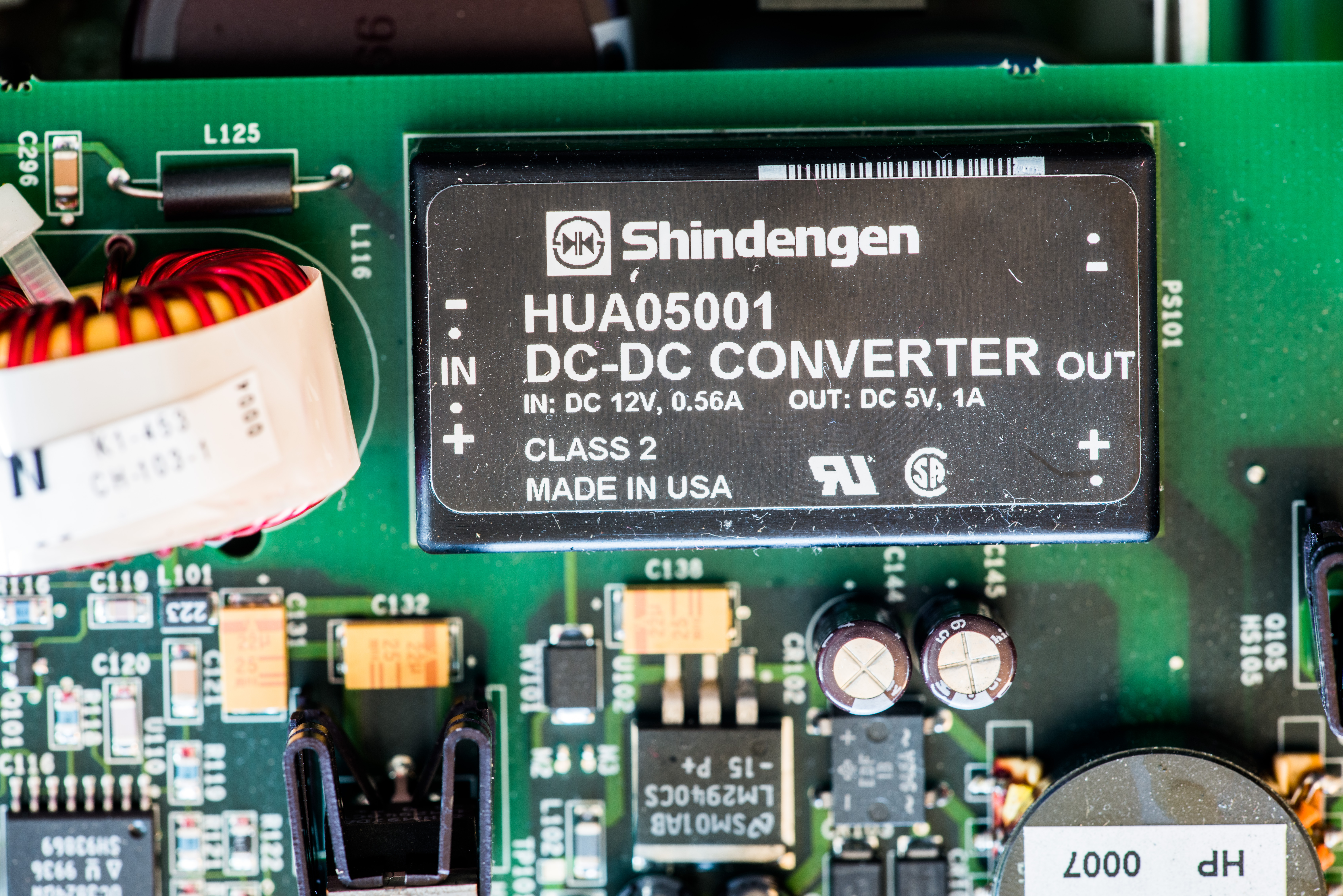
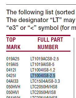
As Linear Top markings document shows, 0425 code corresponds to LT1004CS8-2.5 20ppm/°C voltage reference
Repair
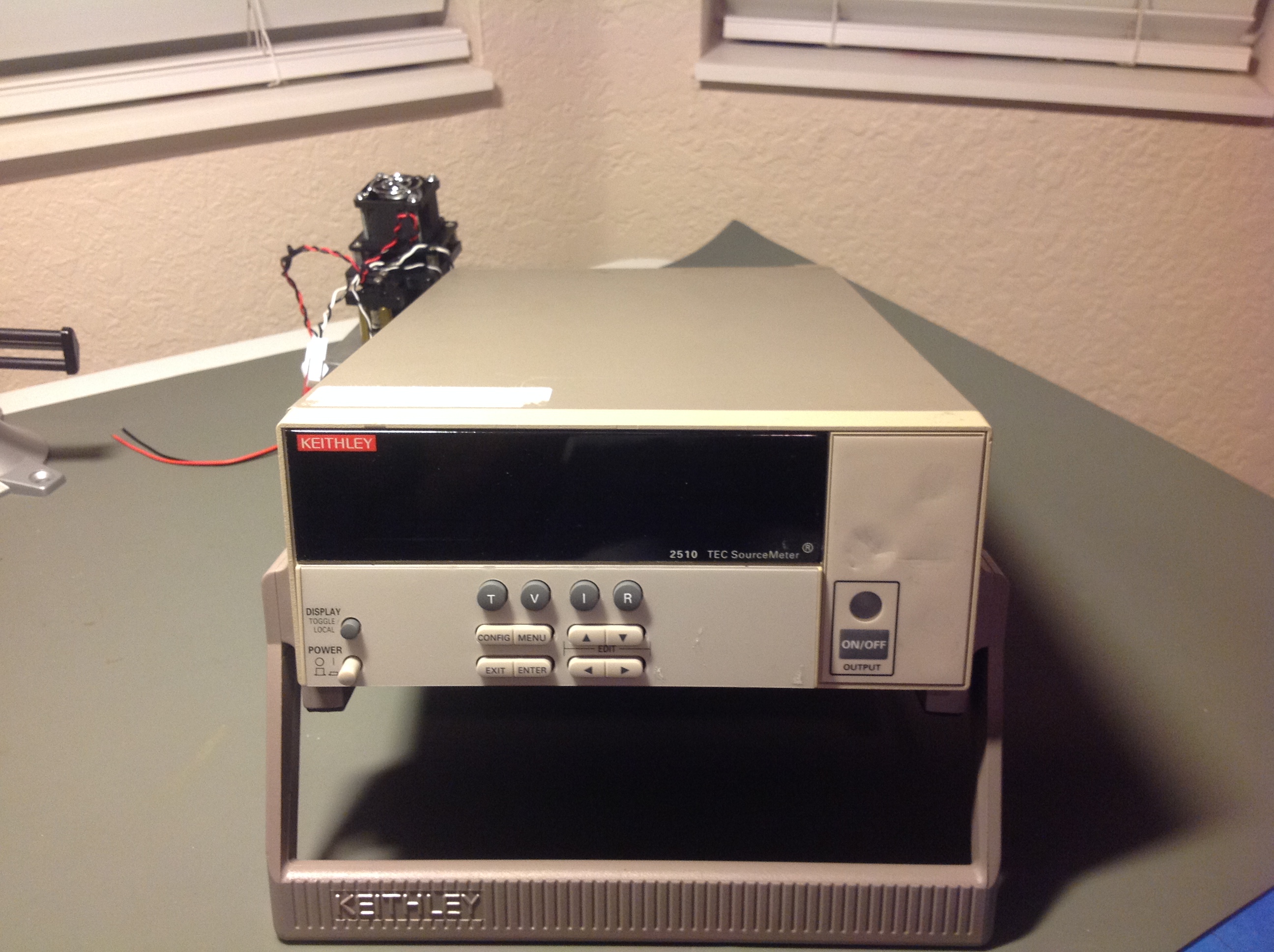
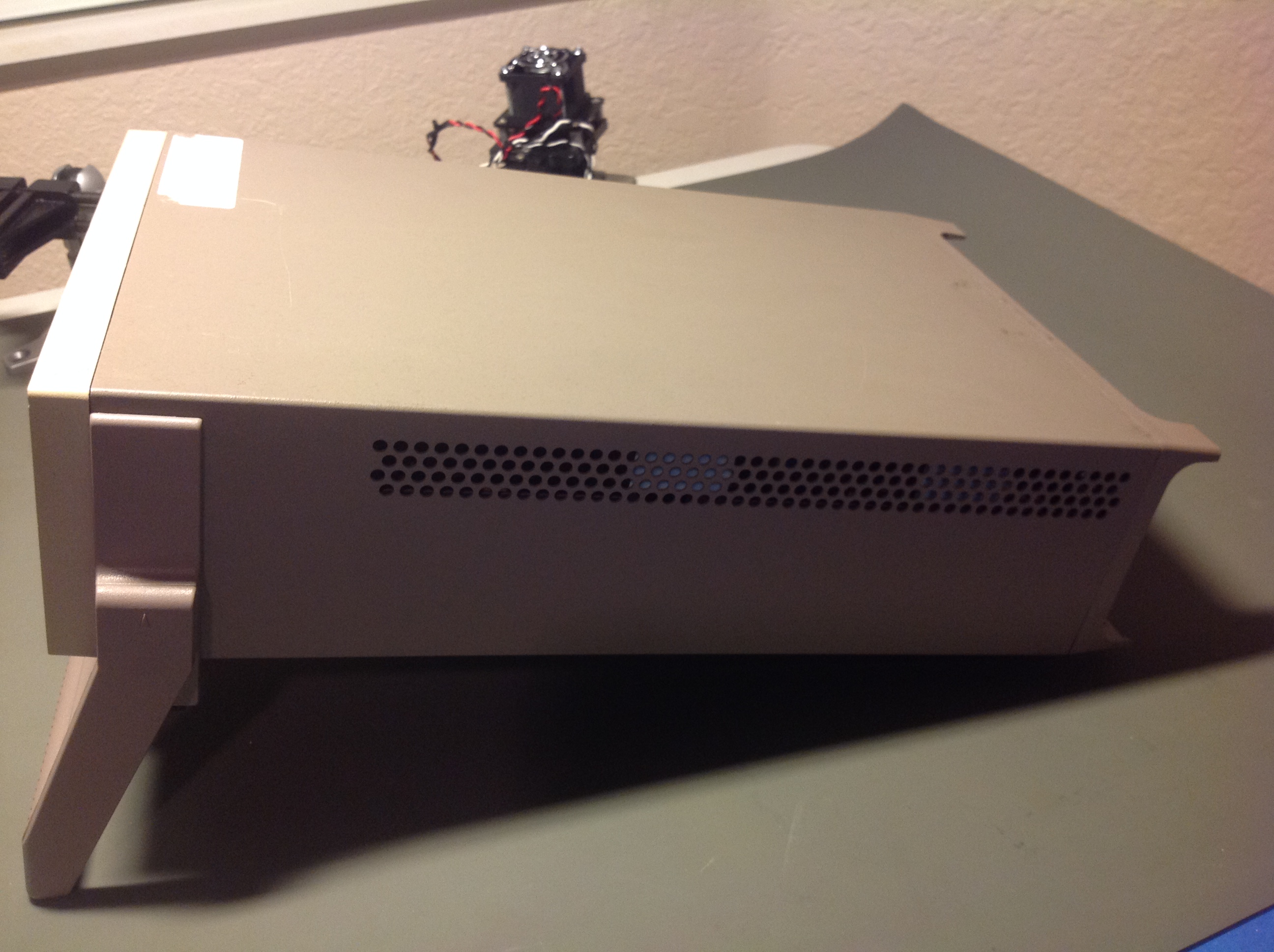
- Get a unit, check for any physical damages. Check VFD.
Done.. No visual damage anywhere. Little dirty outside, but everything nice and clean inside.
Front display board seem to be replaced previously, as datecodes on it are from 2007 year, but mainboard components are dated way older, 1999.
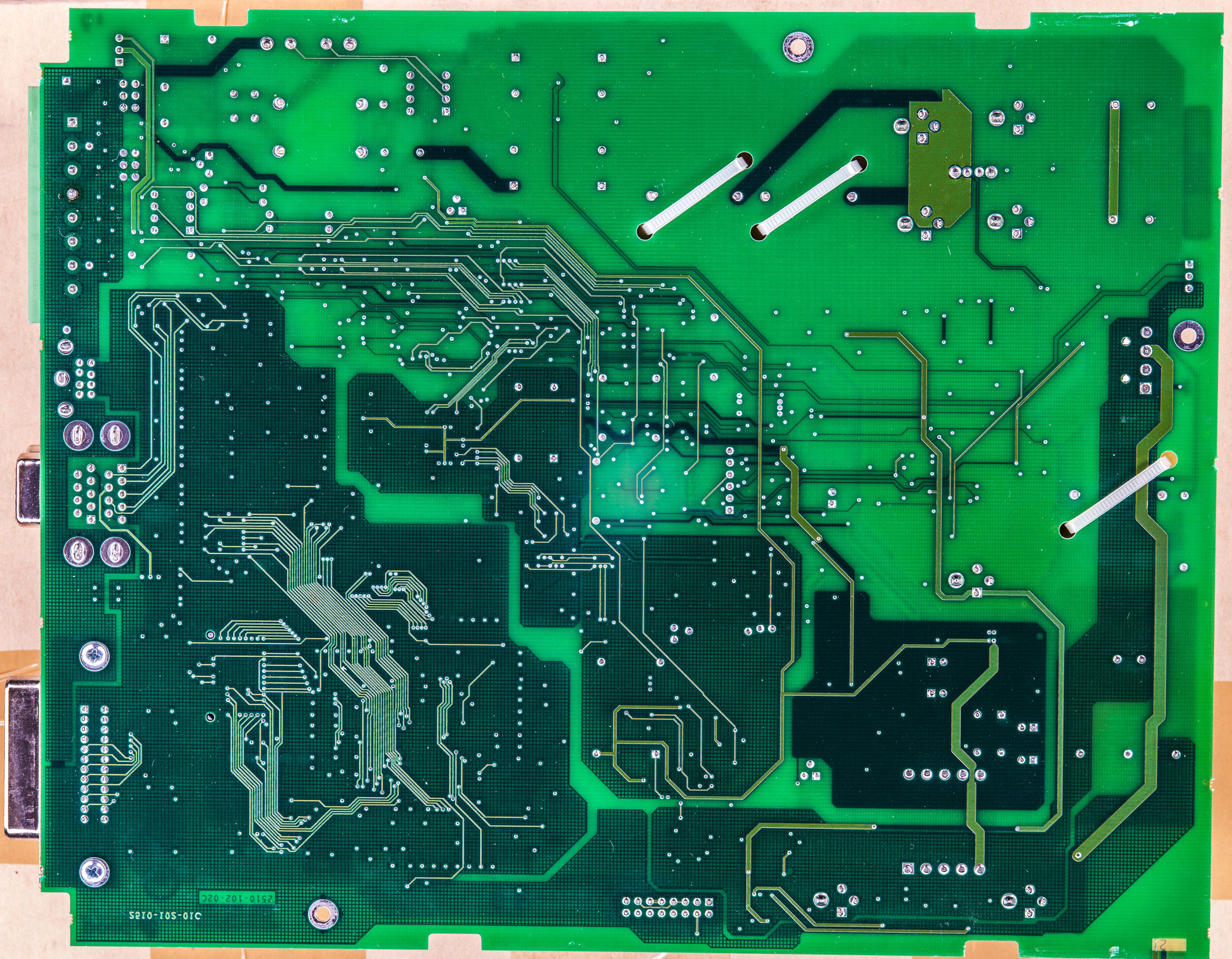
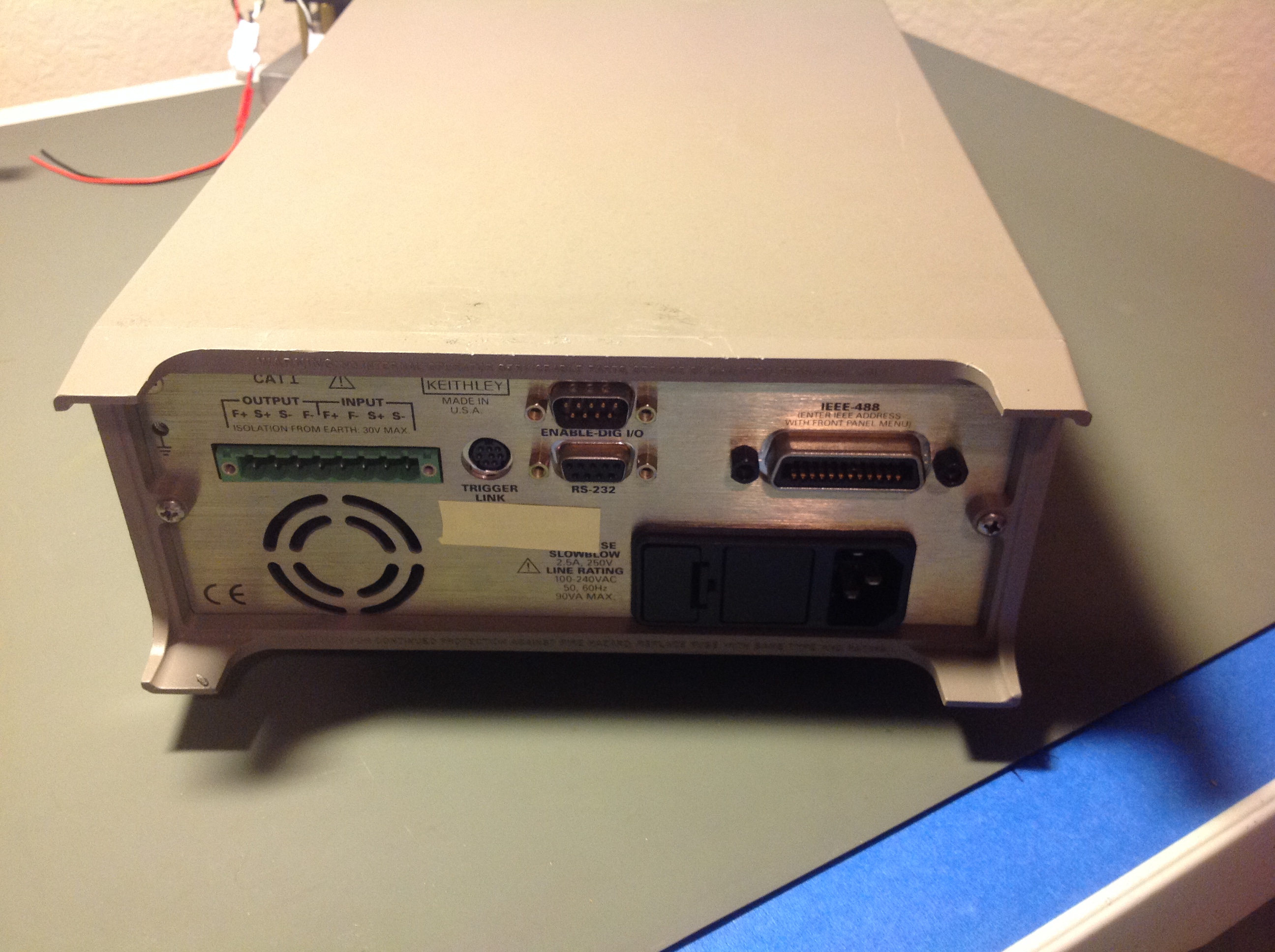
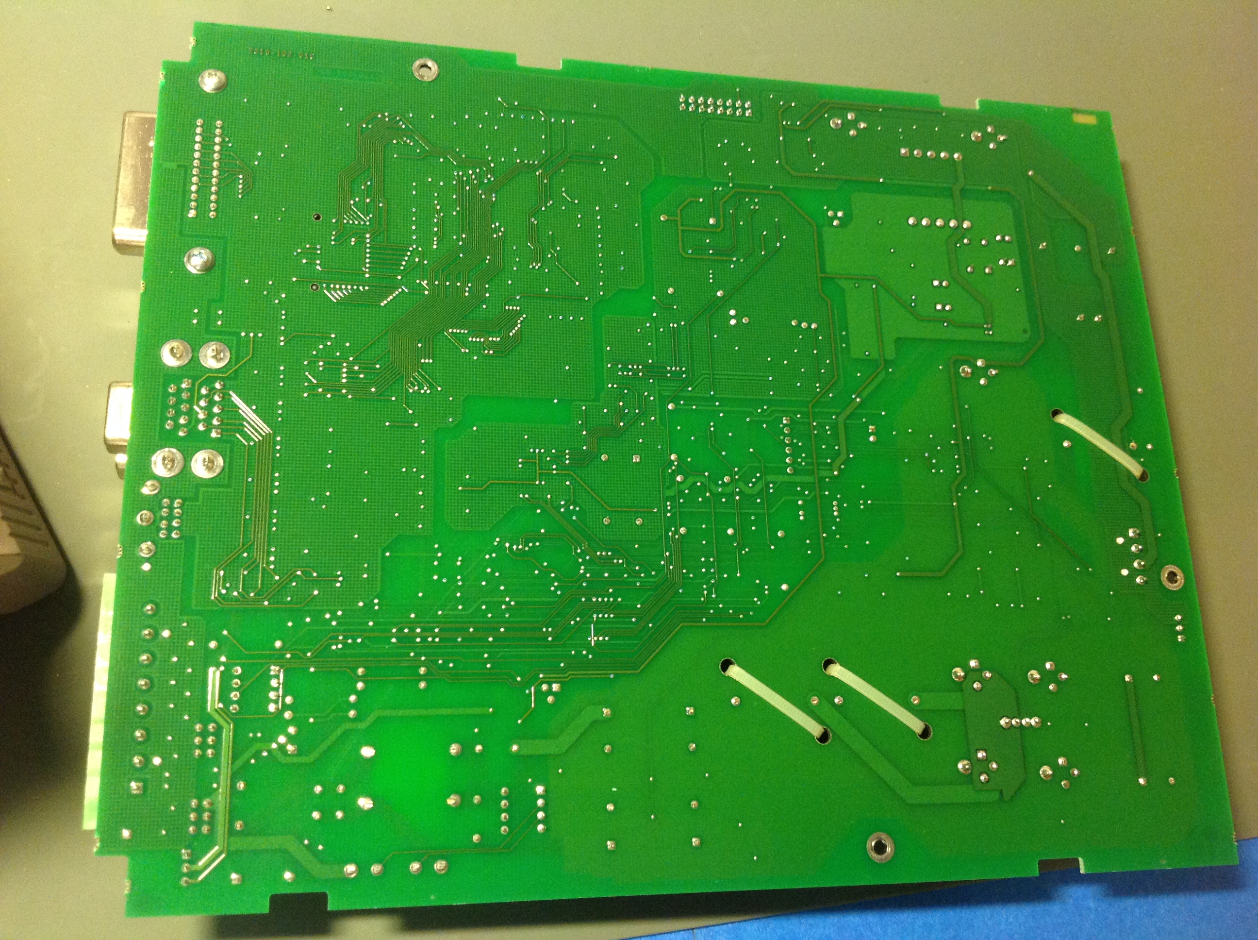
Back of it:

Same board with onboard HV voltage boost is used in Keithley 2002 and 2400. 2001,7001 have HV voltage boost for VFD on their boards, not front panel board.
Face:
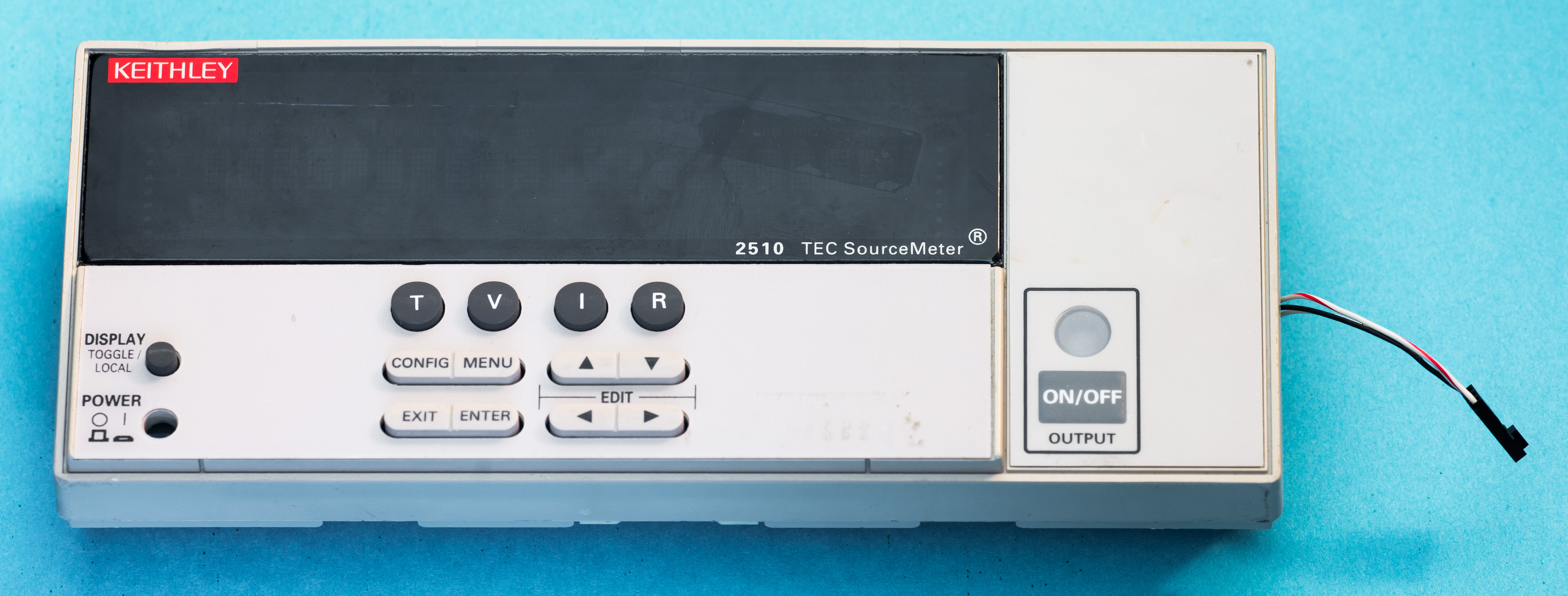
Display board and VFD are fine and working (supplied +5.000VDC from KI2400, VFD draws 0.45ish Amps, and showing “No Comm Link” which is what MCU on display board outputs if no serial link data received.

- Check any leaking caps, burnt/missing components, relays.
Done, everything seems fine visually. Relay coils are likely fine, no shorts/opens.
- Power unit on, check voltages, +10.4V, +4V, +6.3V, -12.5V, +12.5V, 0V, 0.5V, 5V
Power on – no visible changes are happening. None segments lit on front panel display, no reaction on output button toggle, no buzz or fuzz.
Time to do some checking test points using Keithley 2001 as per service manual.
| Test point | Measured | Result |
|---|---|---|
| J1033 front panel +5V | 4.715 VDC | (below -5% specified in manual, but I think it’s OK, just voltage for front panel) |
| J1003 p3 | 14.985 VDC | OK |
| TP102 | 4.980 VDC | OK |
| TP112 | 5.010 VDC | OK |
| TP101 | 14.958 VDC | OK |
| TP105 | -15.162 VDC | OK |
| TP106 | 5.020 VDC | OK |
| TP107 | 4.974 VDC | OK |
Popped firmware PLCC32 into MiniPro to read it (ATMEL AT49F040 chip), as it have sticker 2510-800-A11, and
tada…
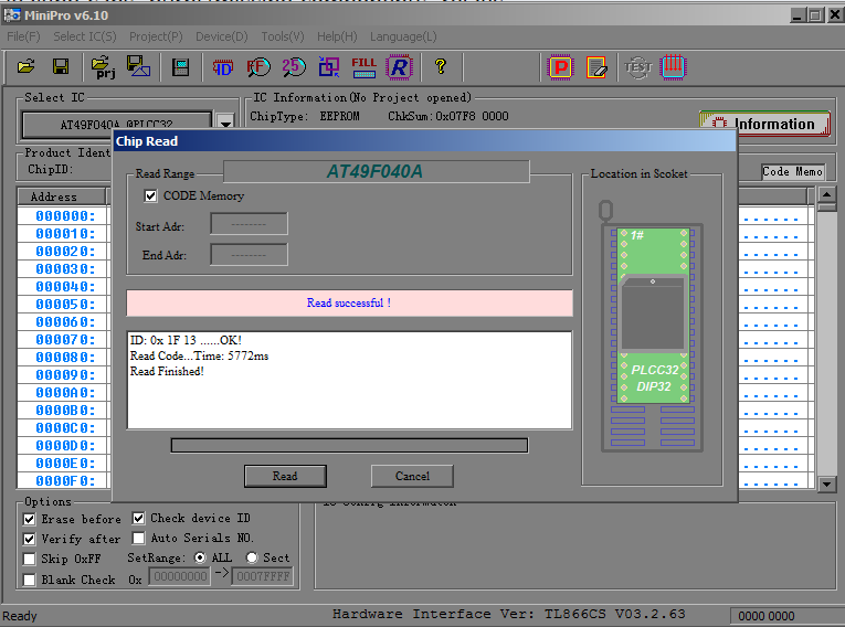
It’s blank (all bytes 0xFF).. Definately not normal!
![]()
Flashed it with C32 firmware from Keithley 2400, now it shows No Comms Link…
So it’s a “progress”, meaning it might be just missing firmware…
Time to get some community help, a firmware dump of AT49F040 PLCC32 ROM to be exact.
And help come from Keithley/Tektronix forums shared firmware for 2510, so as expected, everything booted up fine after flashing.

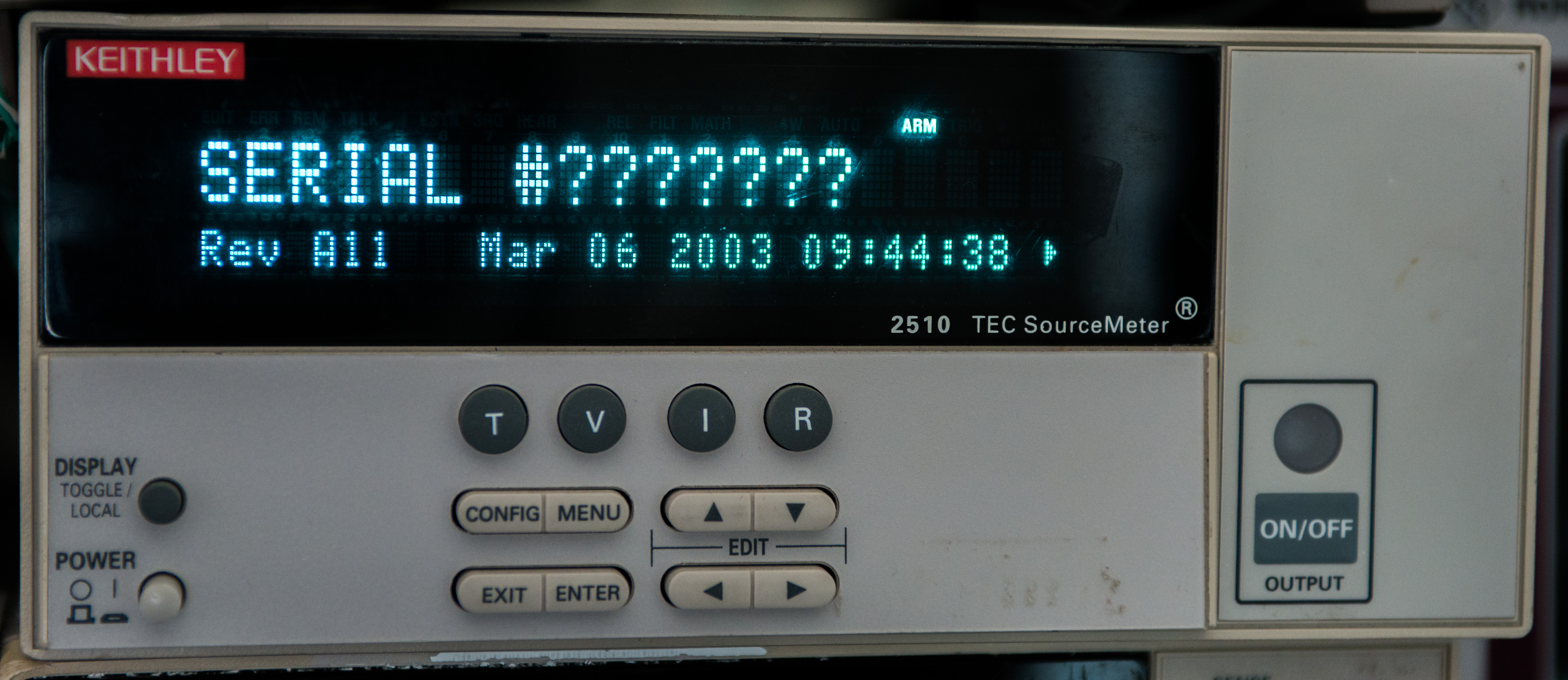
Boot message
Performance check and calibration
Now since unit able to power on and responds to all commands and controls normally, it’s time to check if it’s actually working properly and sourcing/measuring signals.

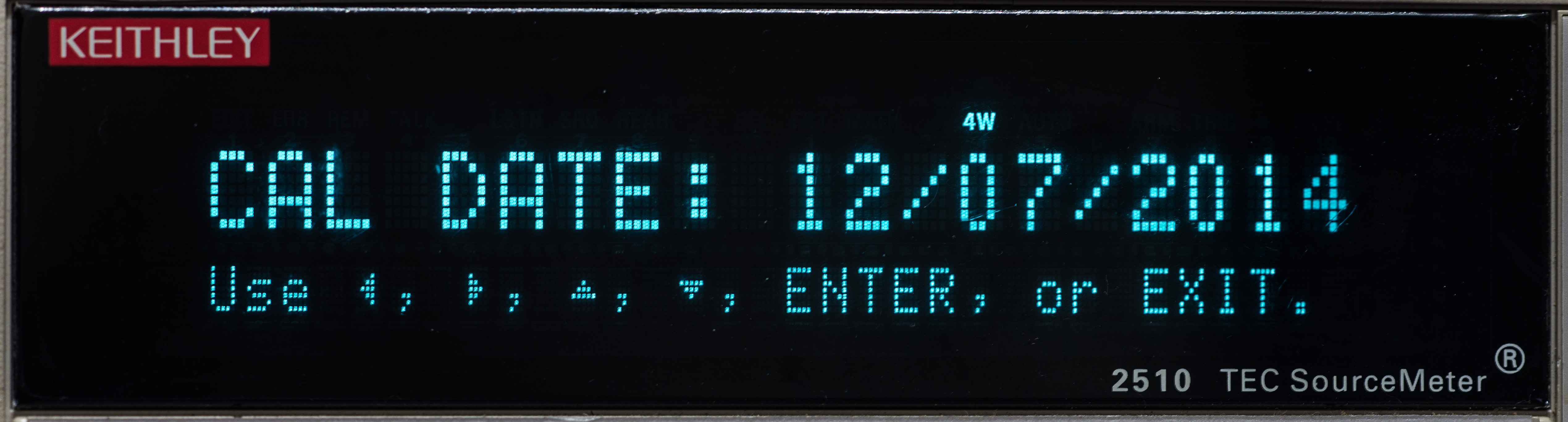
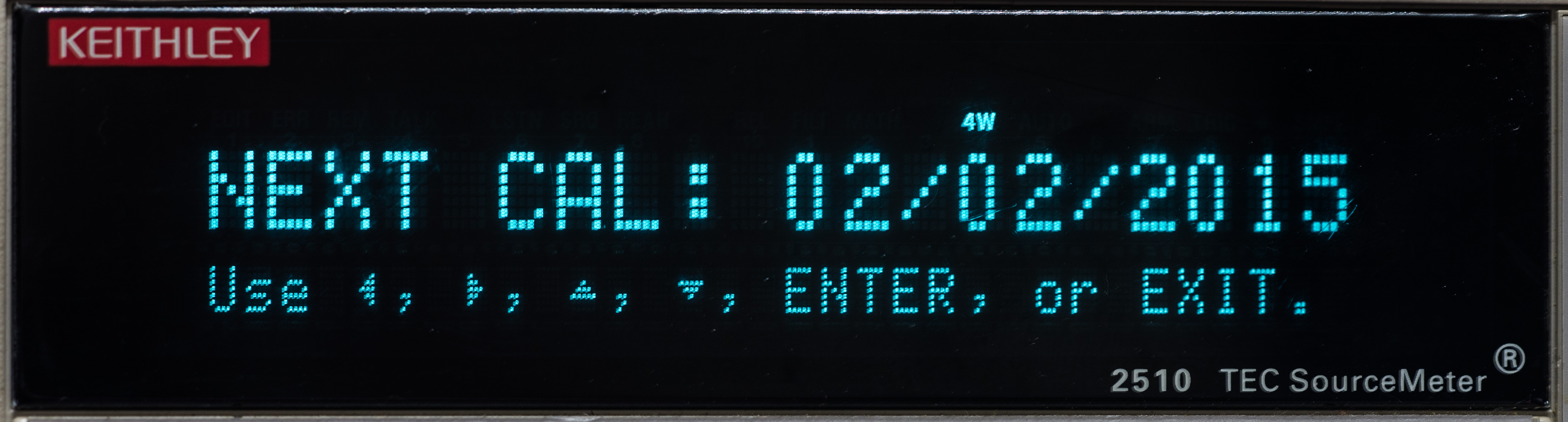
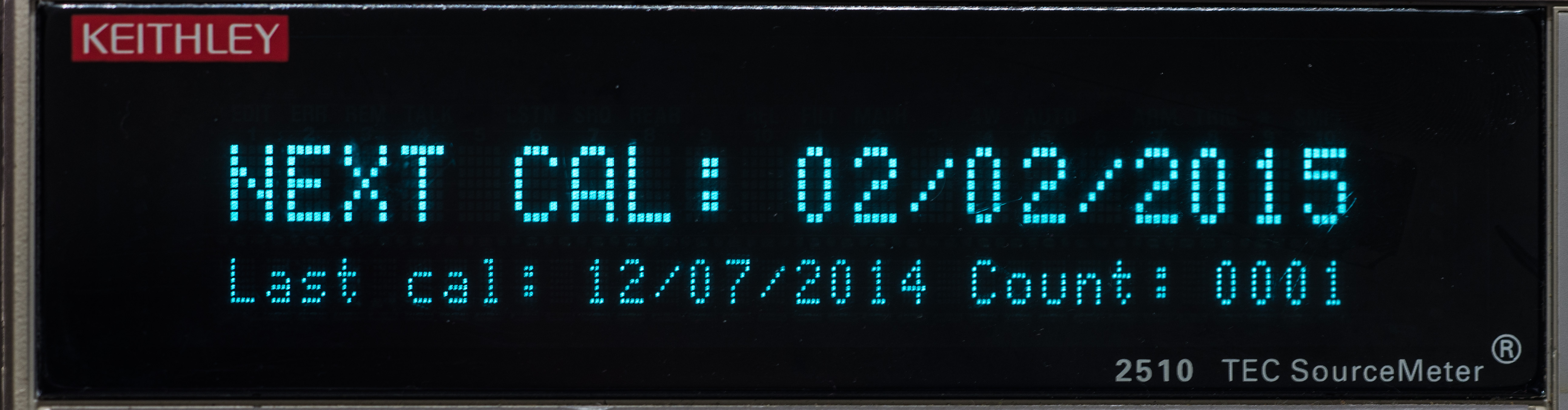
Calibration dates

Calibration might be corrupted, as serial number is lost.

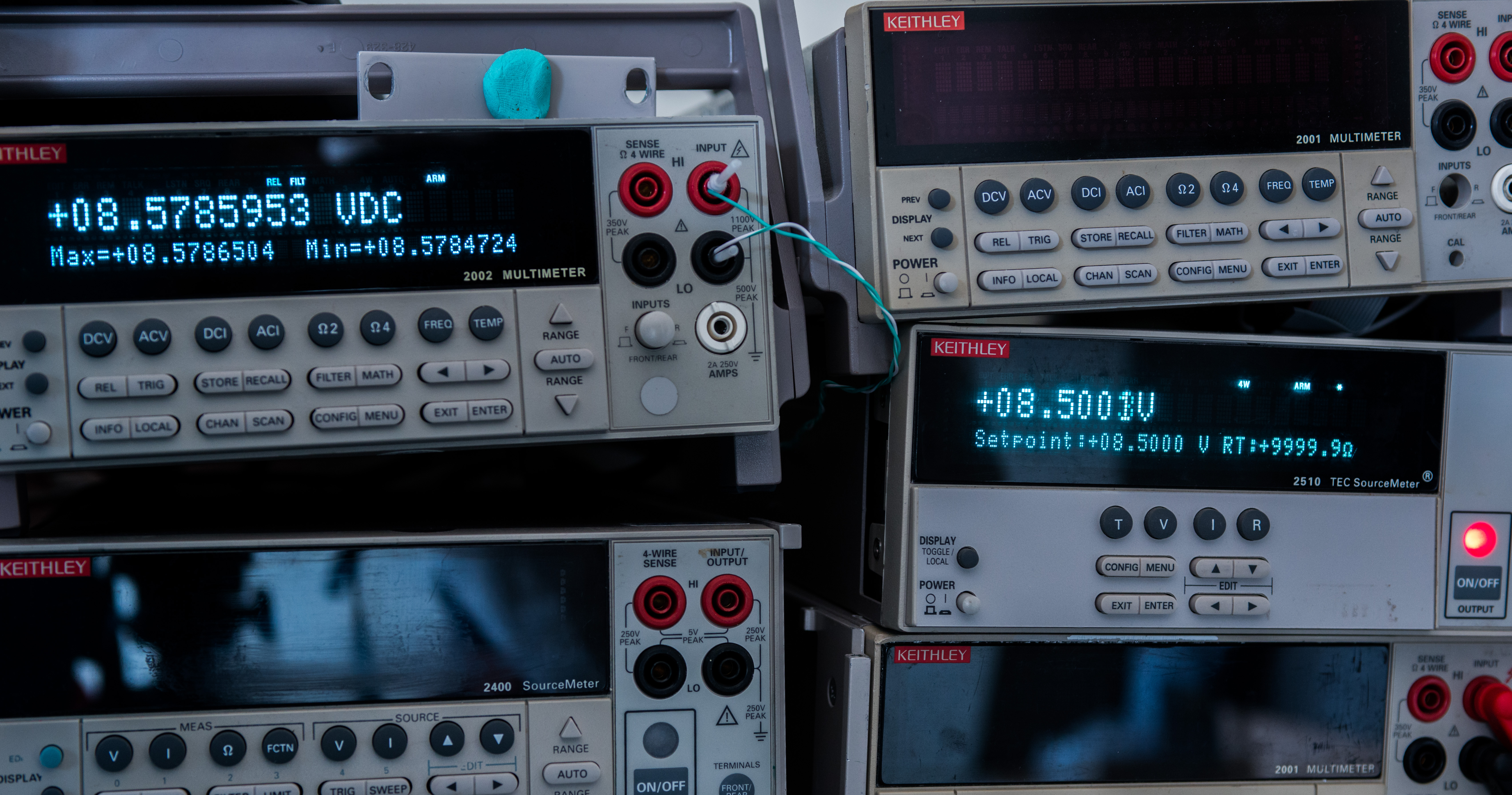
Initial test with 2002 shows that output voltage levels are out of tolerance and specifications.
For calibration of Keithley 2510 need next standards, per calibration manual:
| 1 Ω resistor | ±0.1%, 100W |
| 100 Ω resistor | ±1% |
| 1k Ω resistor | ±1% |
| 10k Ω resistor | ±1% |
| 100k Ω resistor | ±1% |
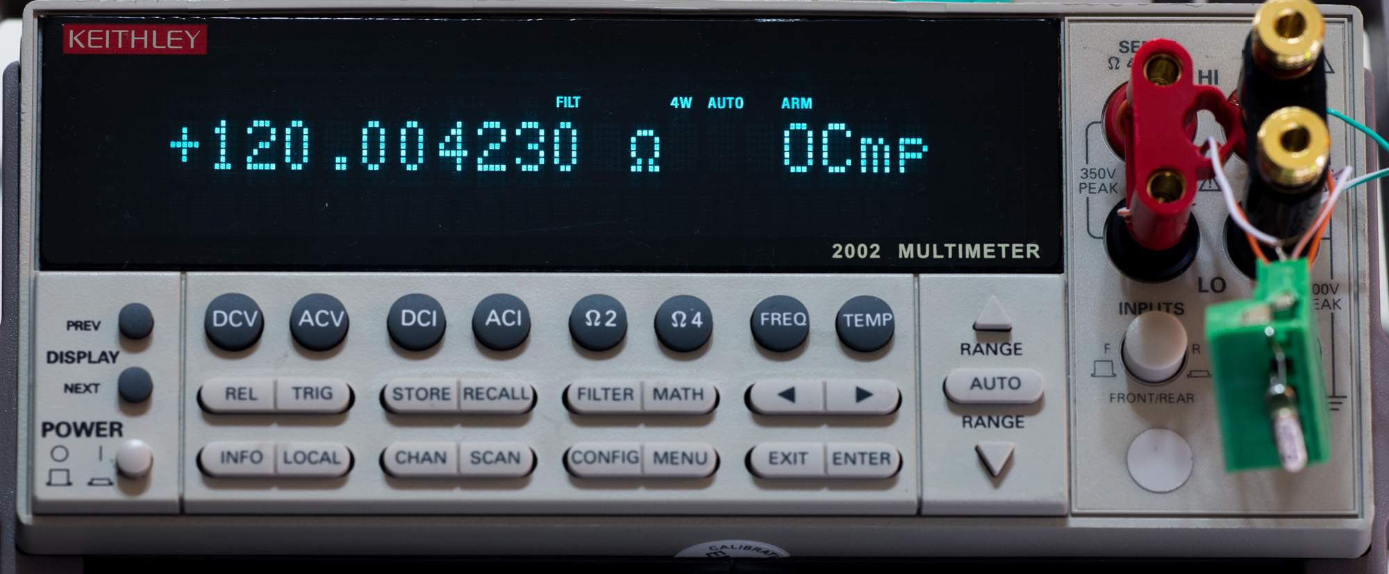
For measurement they recommend using Keithley 2002:
Specification 2002’s ranges:
| DC Voltage | 20VDC | ±6.8ppm |
| Resistance | 20Ω | ±23ppm |
| Resistance | 200Ω | ±19ppm |
| Resistance | 2kΩ | ±7.4ppm |
| Resistance | 20kΩ | ±7.4ppm |
| Resistance | 200kΩ | ±29.8ppm |
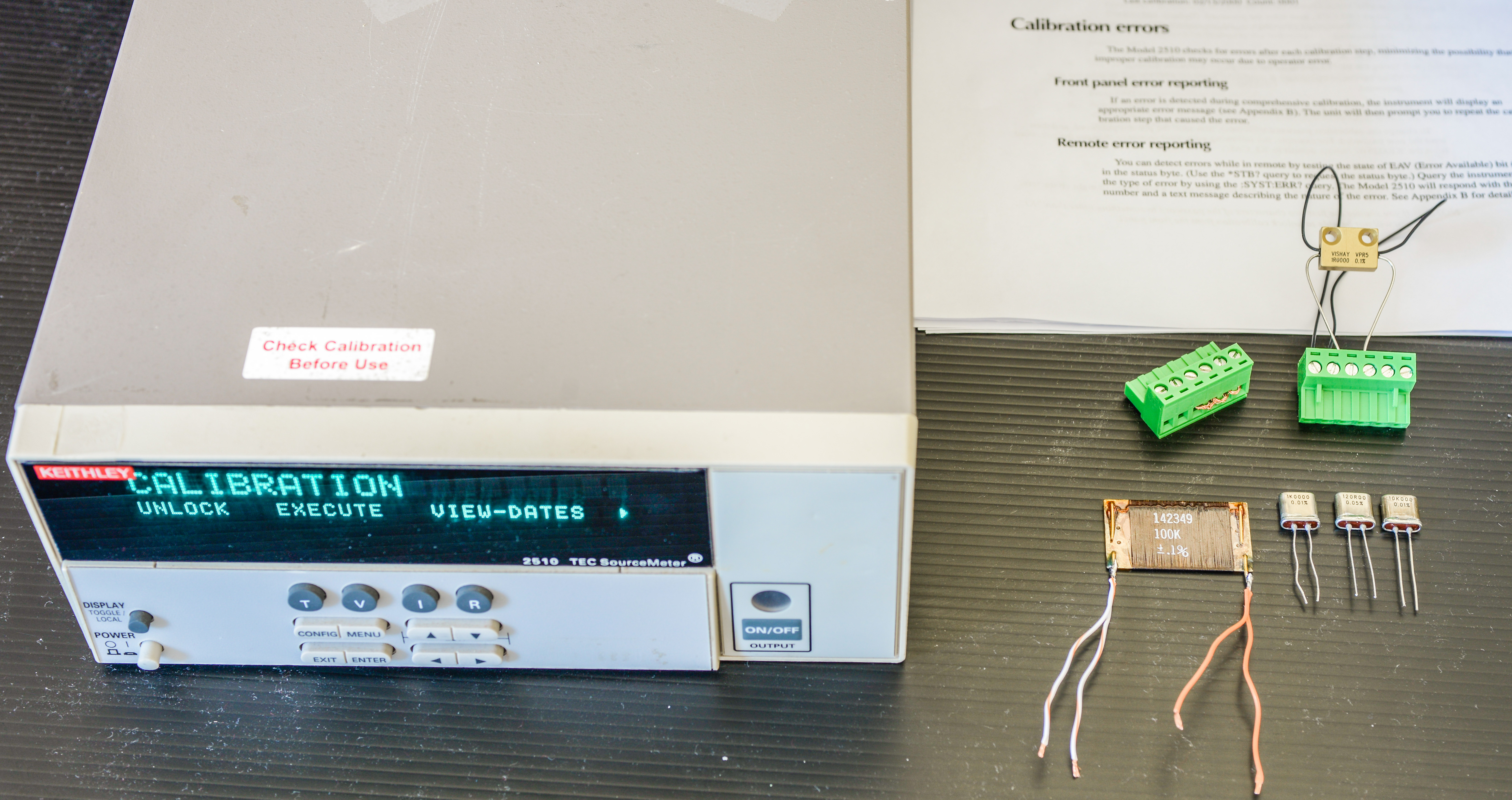
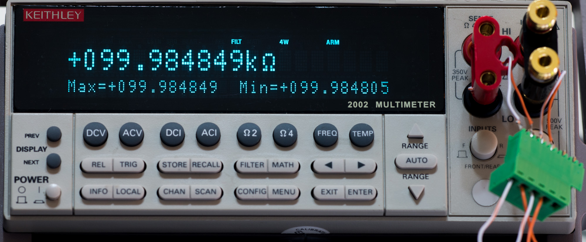
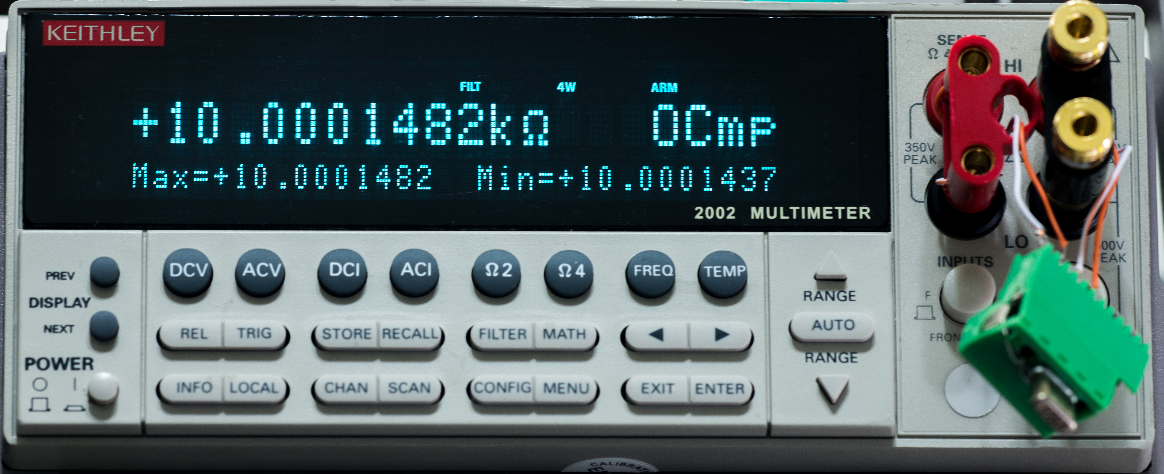
Resistors used for calibration as standards:

| Resistance | Measured | Type |
| 1 Ω | 0.9999061 Ω | Vishay VPR5 1R0000 0.1% 5W 10ppm/K |
| 100 Ω | 120.00420 Ω | VPG VHP202Z 120R00 0.05% 0.2ppm/K |
| 1 KΩ | 1.0000113 kΩ | VPG VHP202Z 1K0000 0.01% 0.2ppm/K |
| 10 KΩ | 10.000143 kΩ | VPG VHP202Z 10K000 0.01% 0.2ppm/K |
| 100 kΩ | 99.984827 kΩ | Fluke wirewound 142349 100K 0.1% 5ppm/K |
Resistors characterization, +26°C room temp, 10 NPLC, 8½-digit Keithley Model 2002, +3.52°C from Tcal.

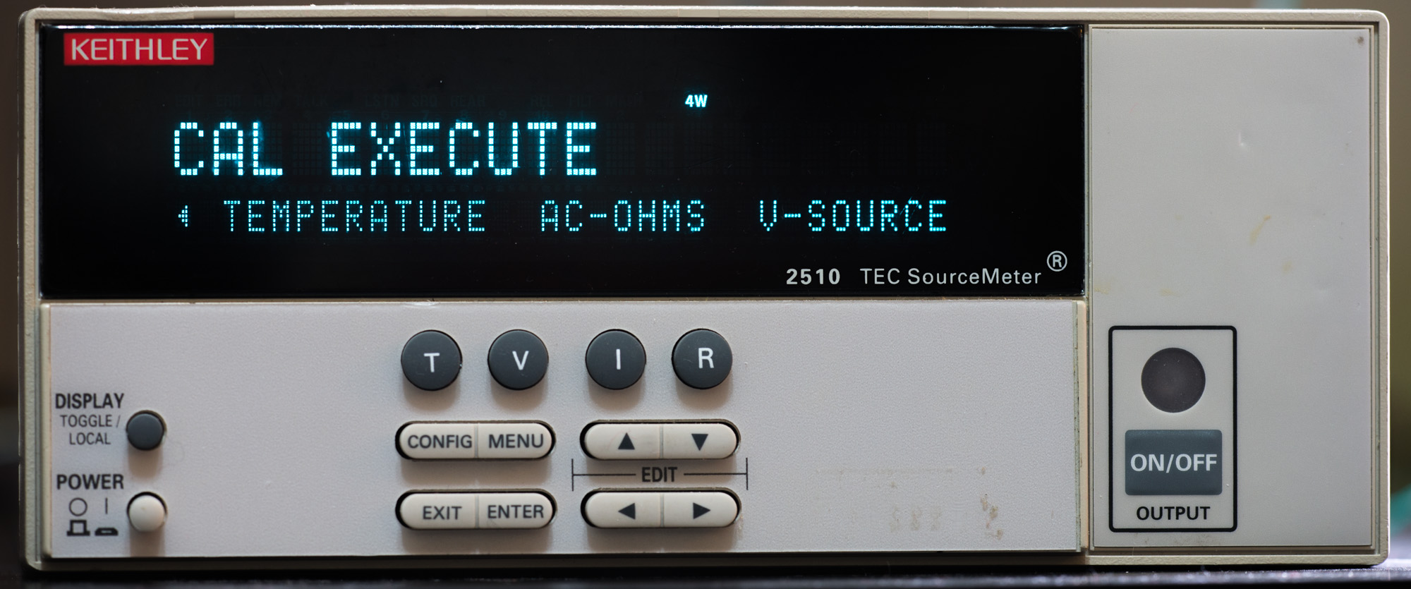
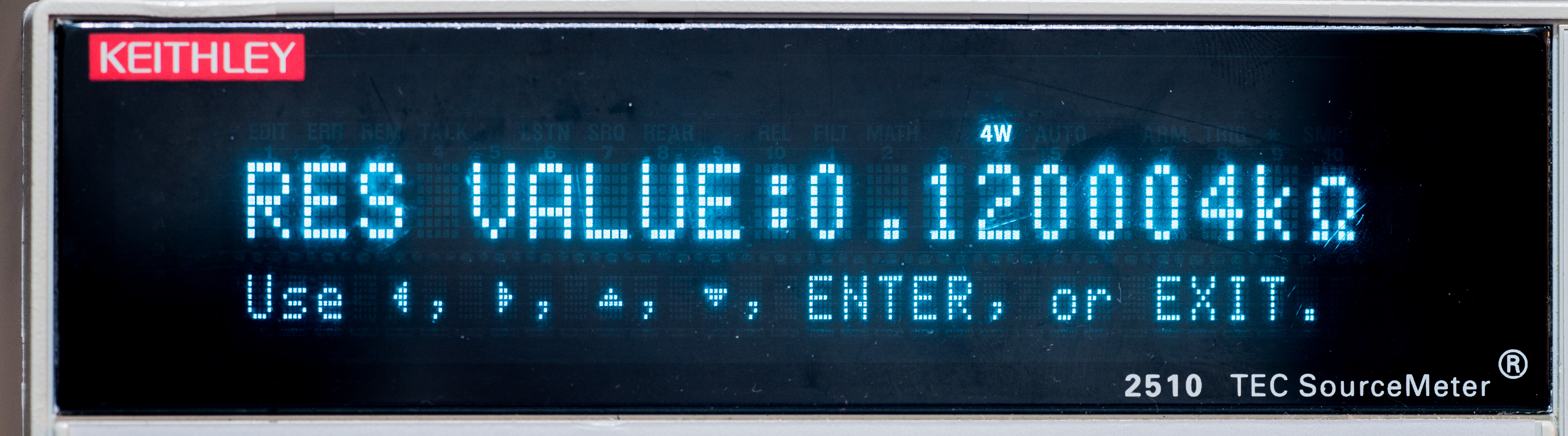
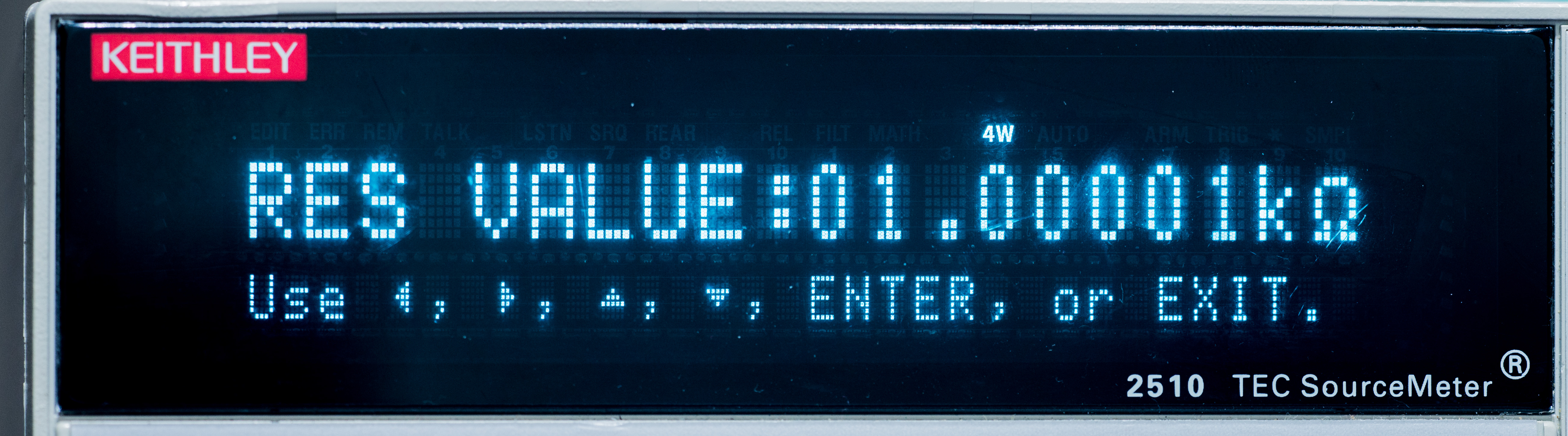
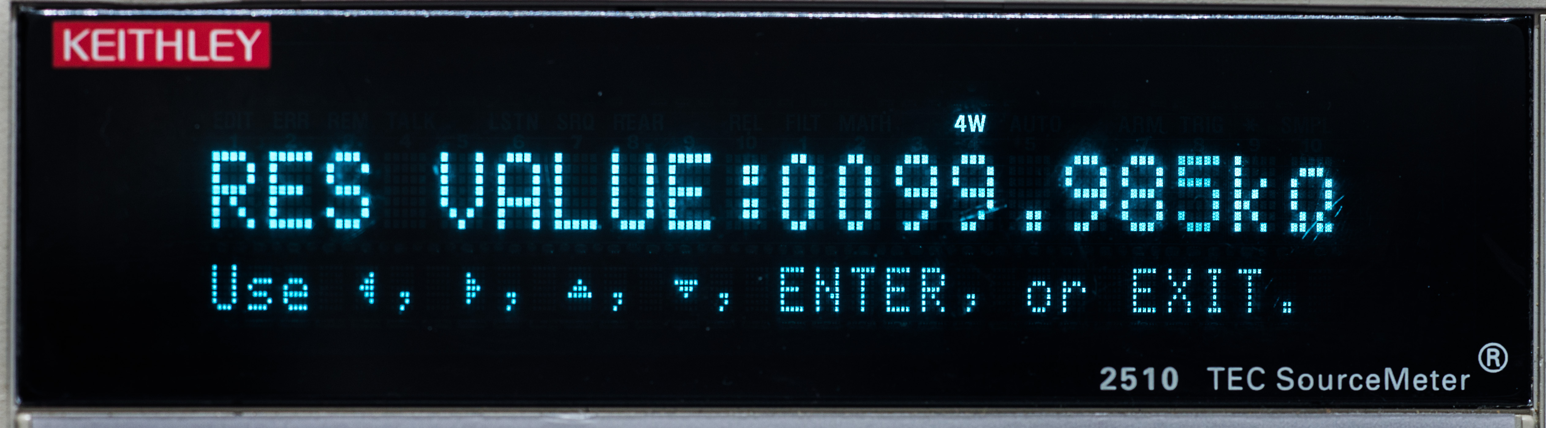
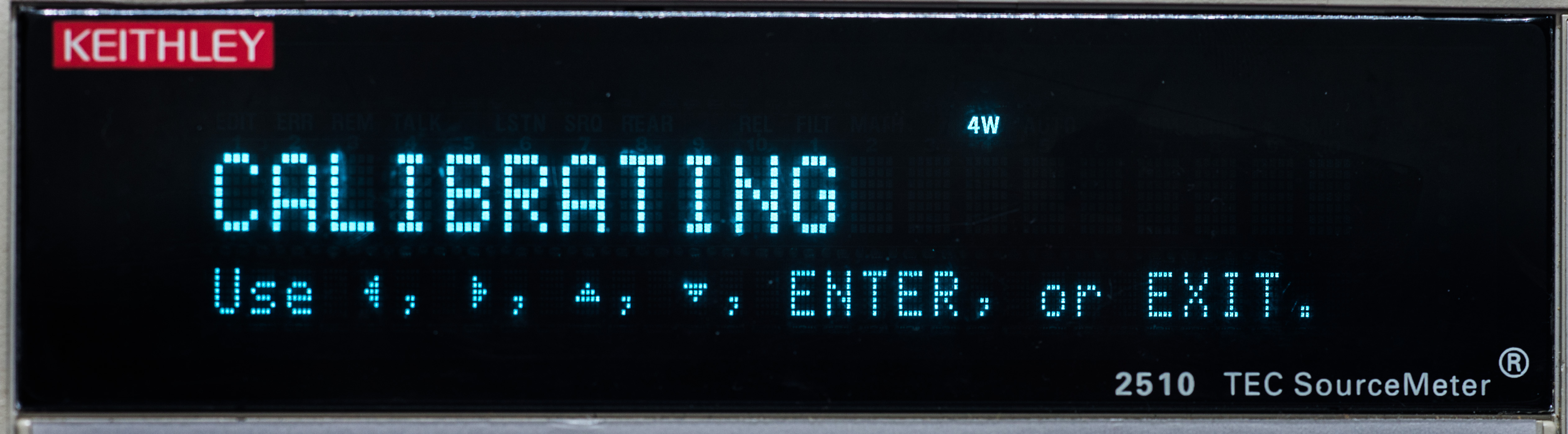
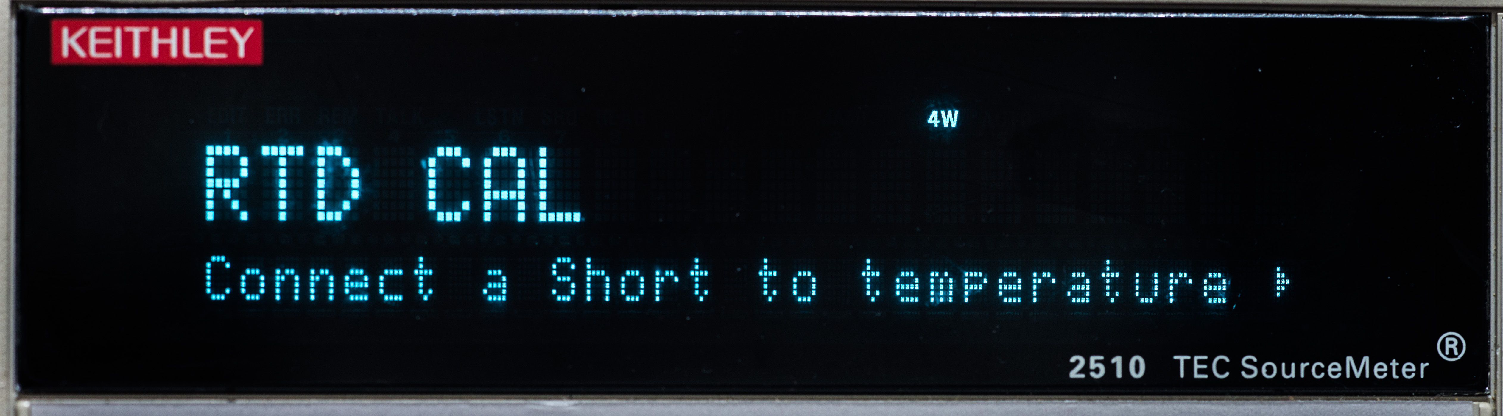
Various calibration steps, entering measured resistance values into K2510


Finish, enter new dates…
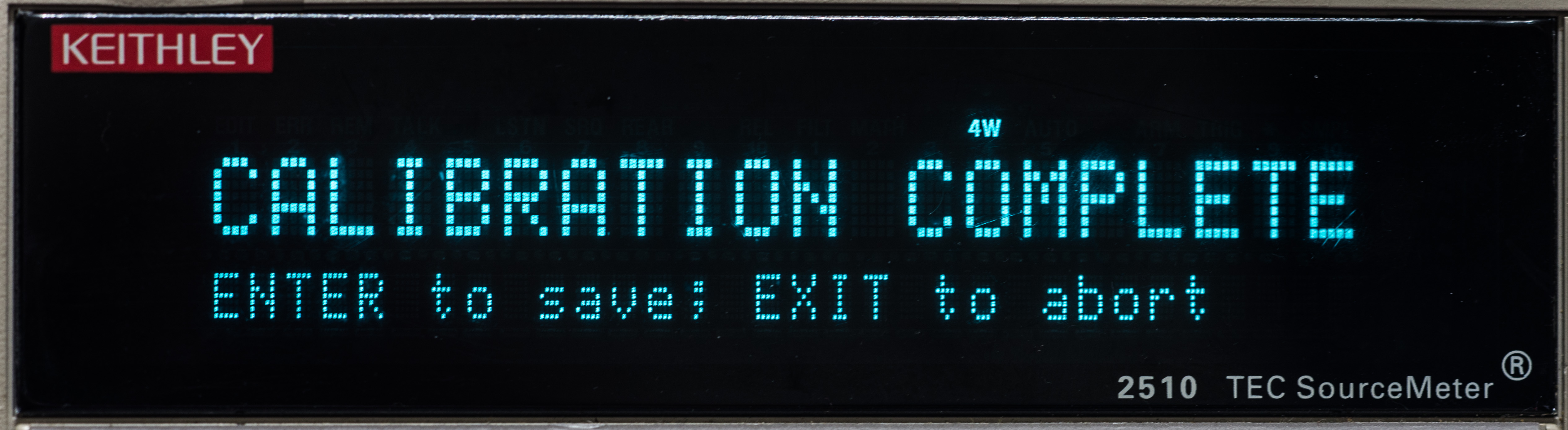
Result constants are:
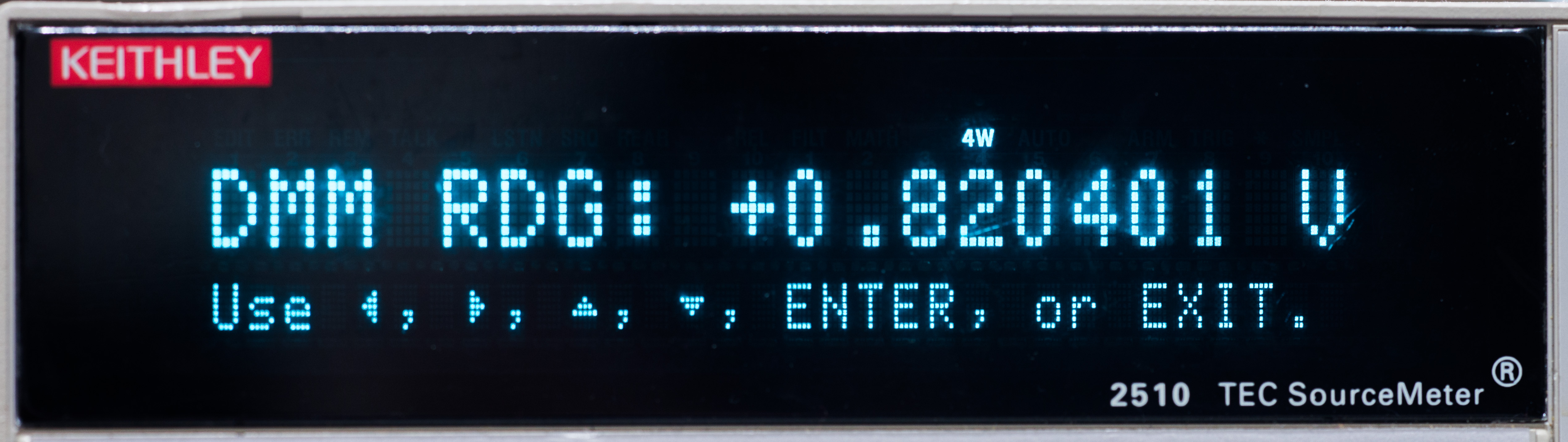
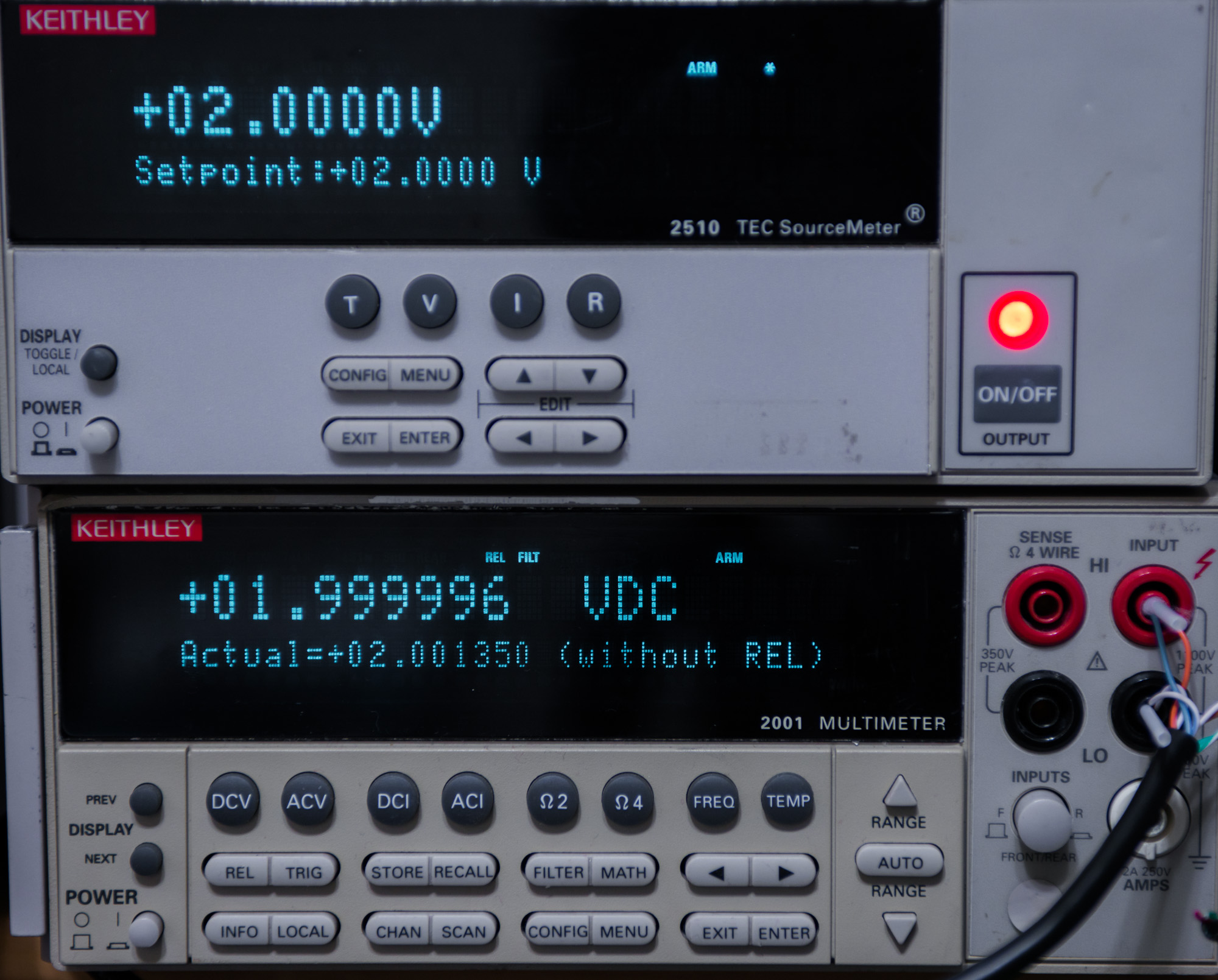
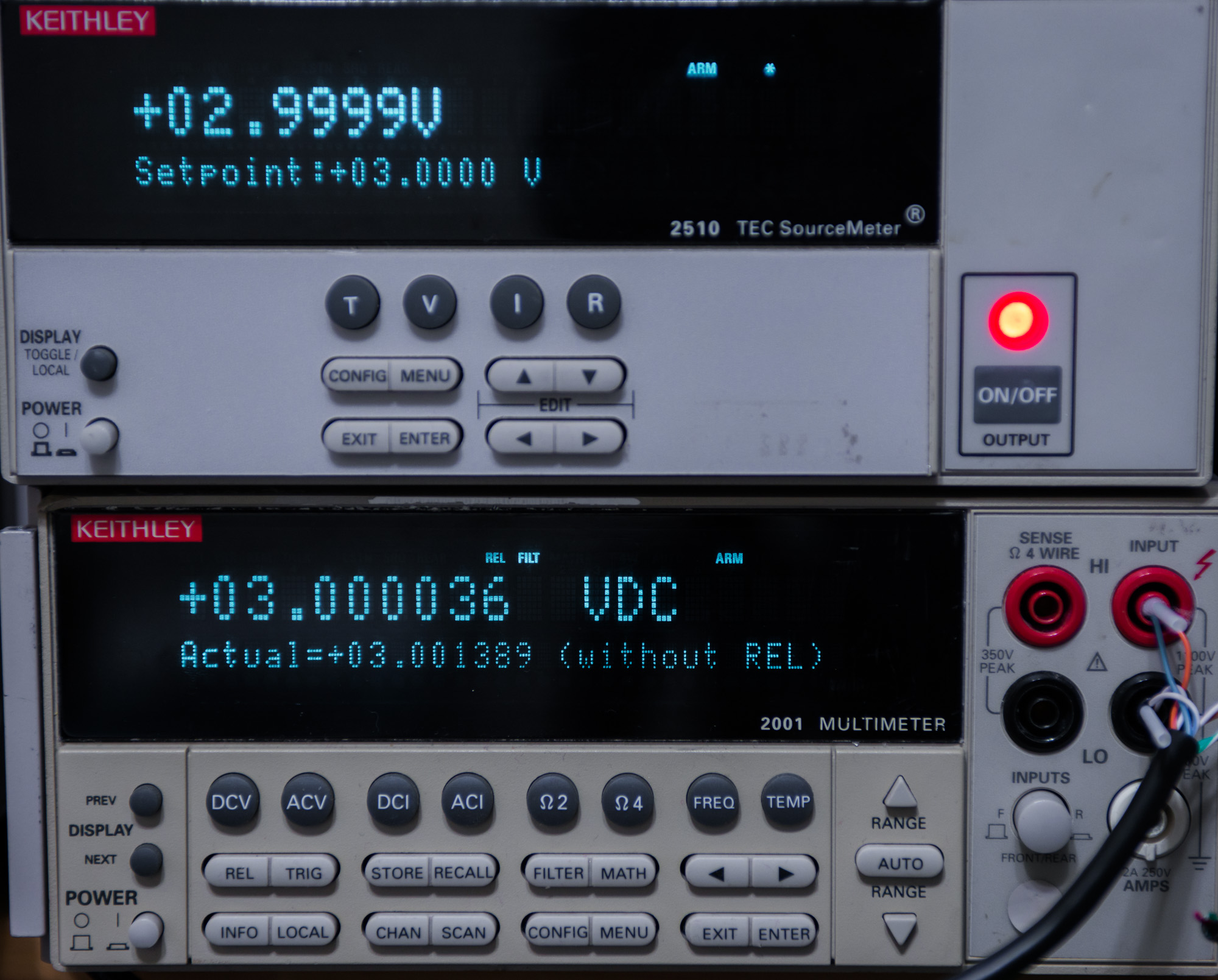
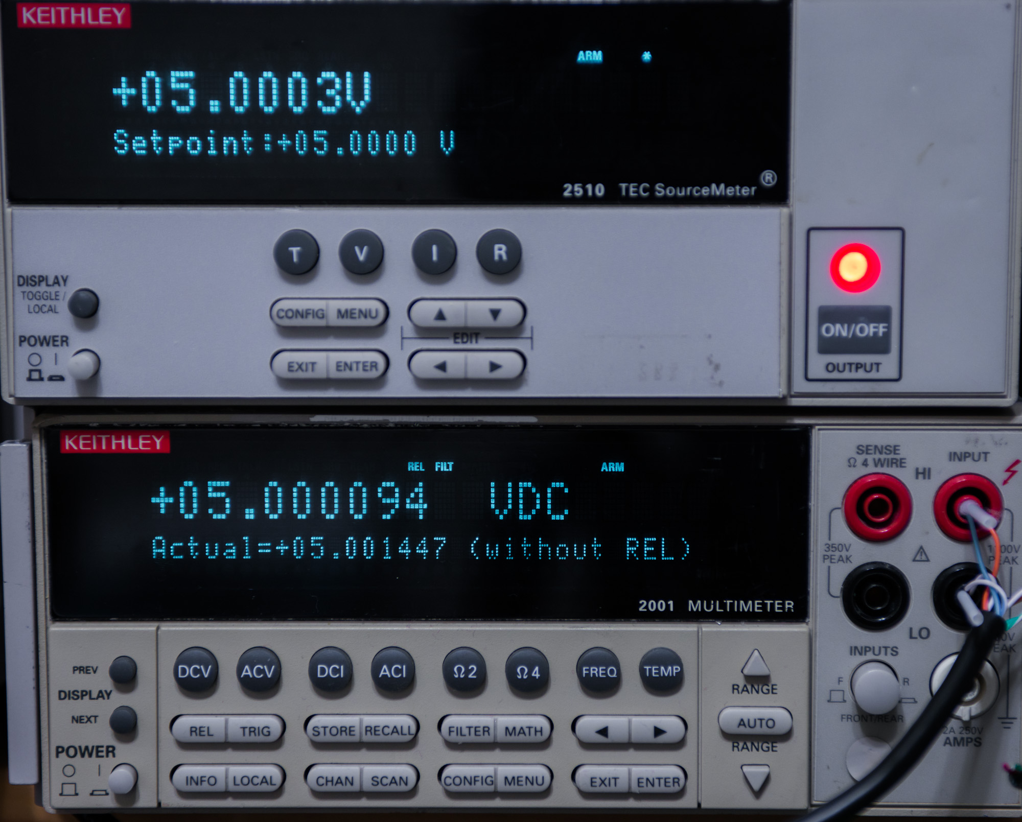
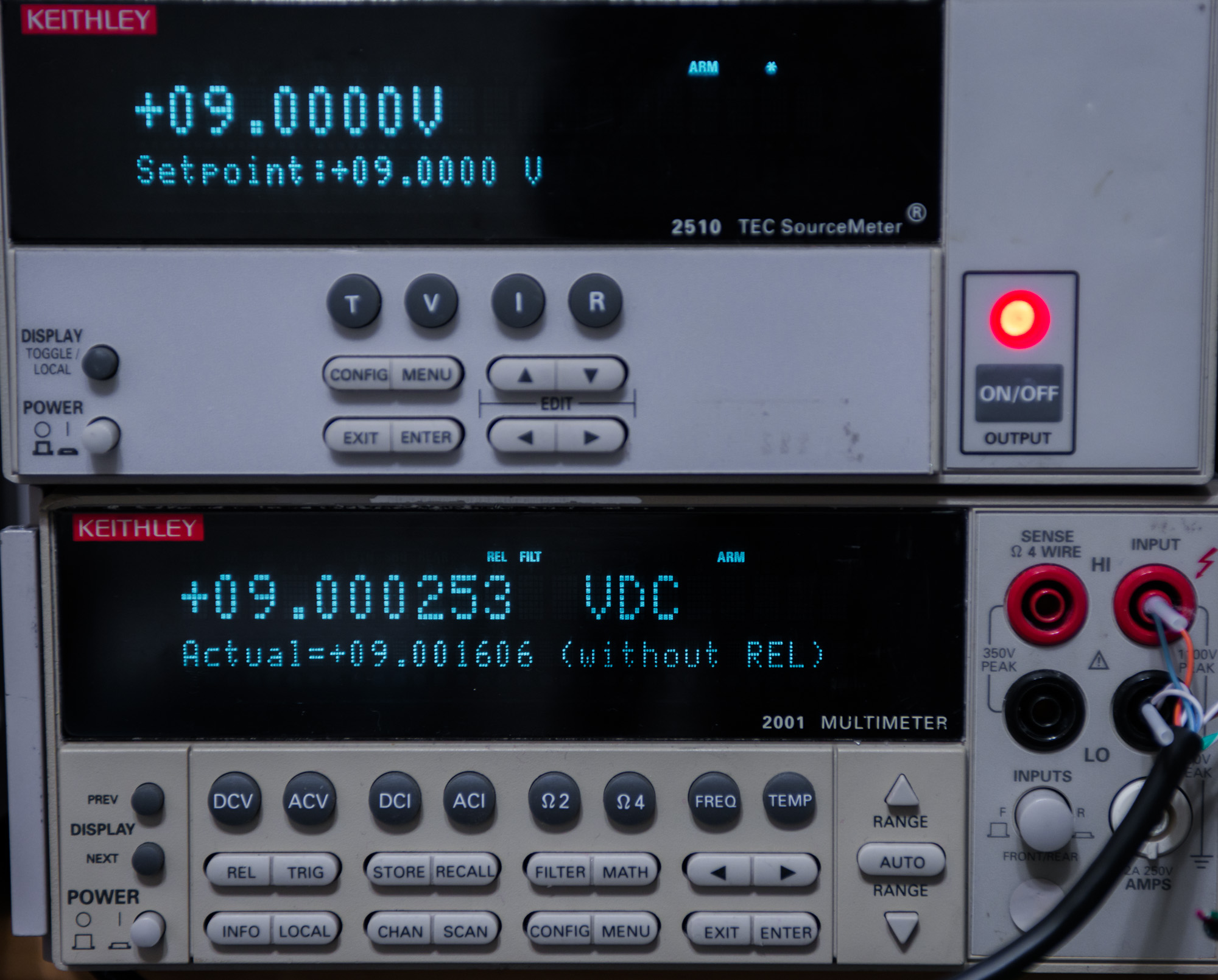
Checking now output voltage with calibrated (in Feb 2014) Keithley 2001.
REL to null output offset (2510 output ON, Set voltage 0.00000 VDC)


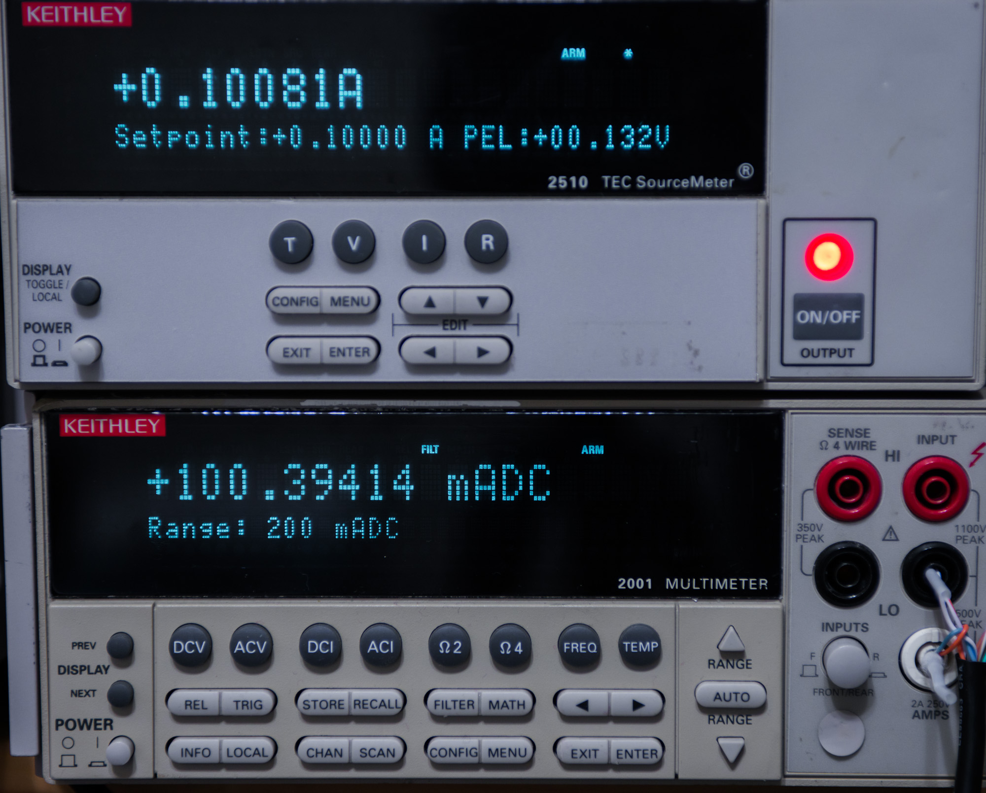
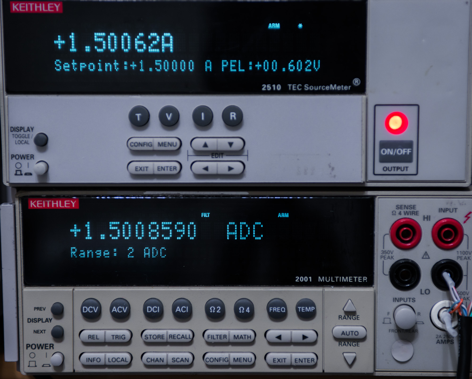
Checking current output source accuracy:


Video of stepping from 0V to +10V and to -10V
Scope screenshots of voltage and current behaviour on turn on/turn off source.
It’s pretty slow during ramps, doing it in steps, but when it get’s there, it’s pretty damn accurate :)


Ramp to 2.0000 Amps into 1.7 Ω resistor

Turn off ramp down

Step measurements.

Repair and calibration is complete.
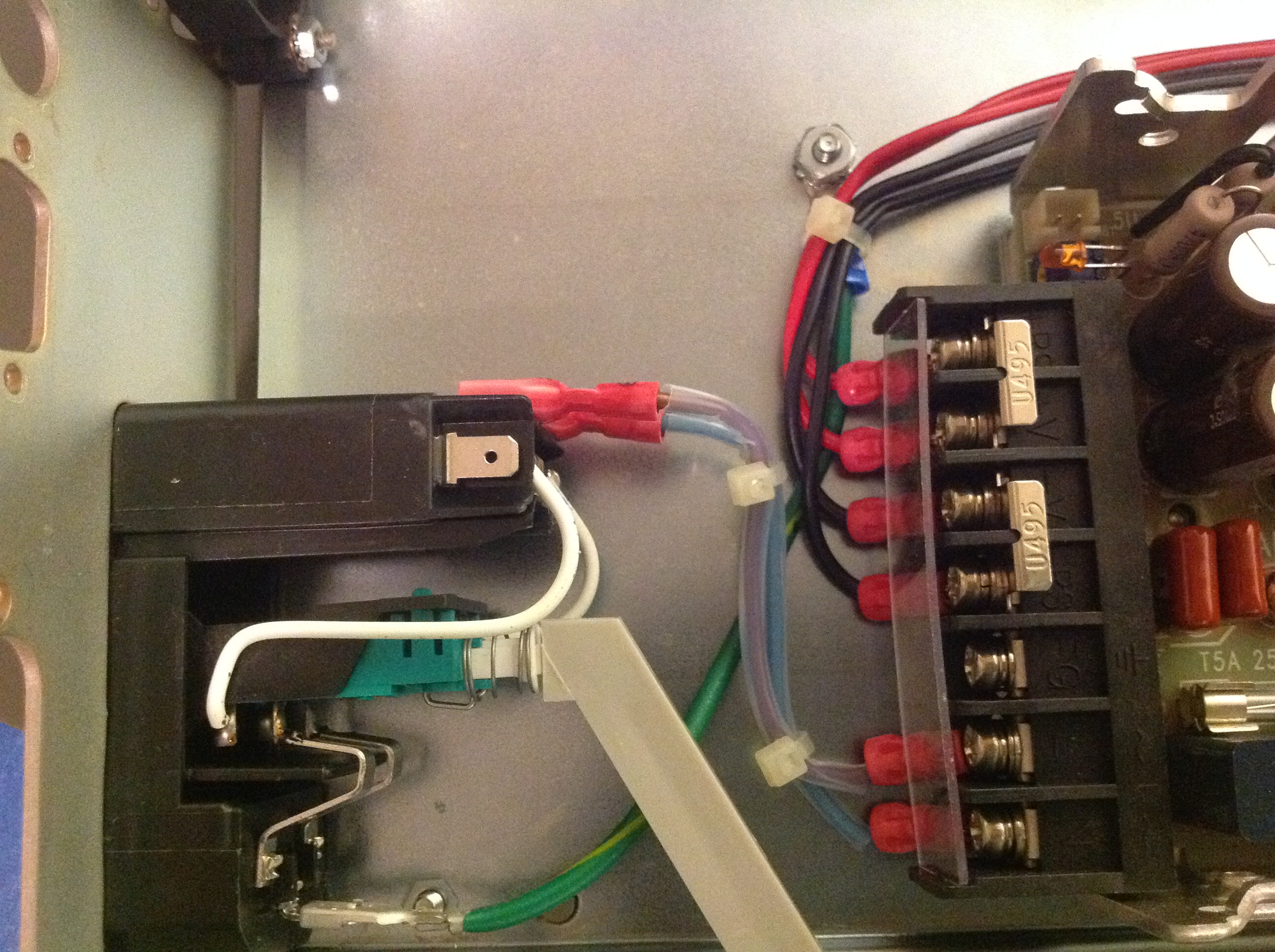
Failure on TEC LO+ Force pin
After years of non-stop operation with TECbox DIY chambers this poor Keithley 2510 failed in June 2022. Output was unable to provide any current into TEC element, but without anything connected was able to supply voltage (still with nearly zero current drive capability). Initial inspection revealed no electrical issues. Closer inspection revealed discolored Force LO pin in Phoenix screw terminal block. This pin connected to TEC output.
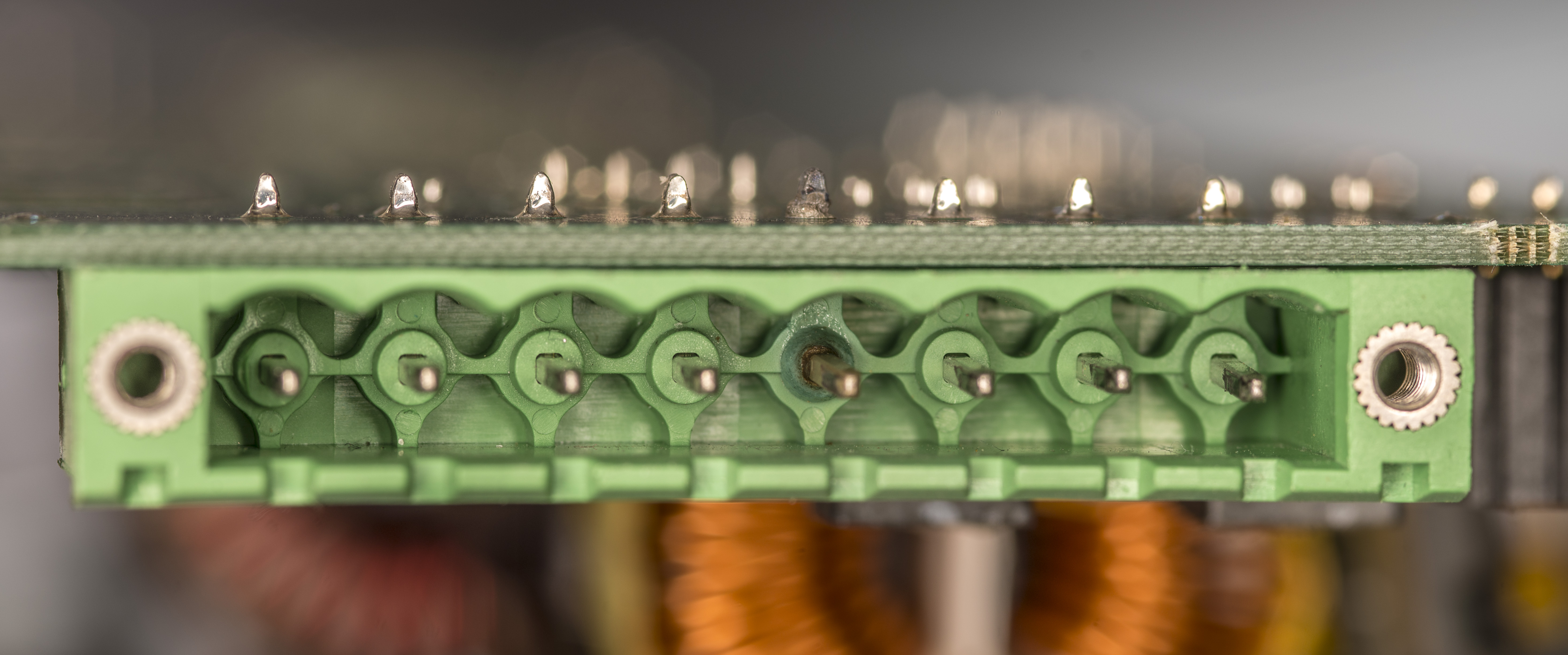
Measuring resistance between connector pin and PCB LO output revealed open circuit failure, with readings in few MΩ range.
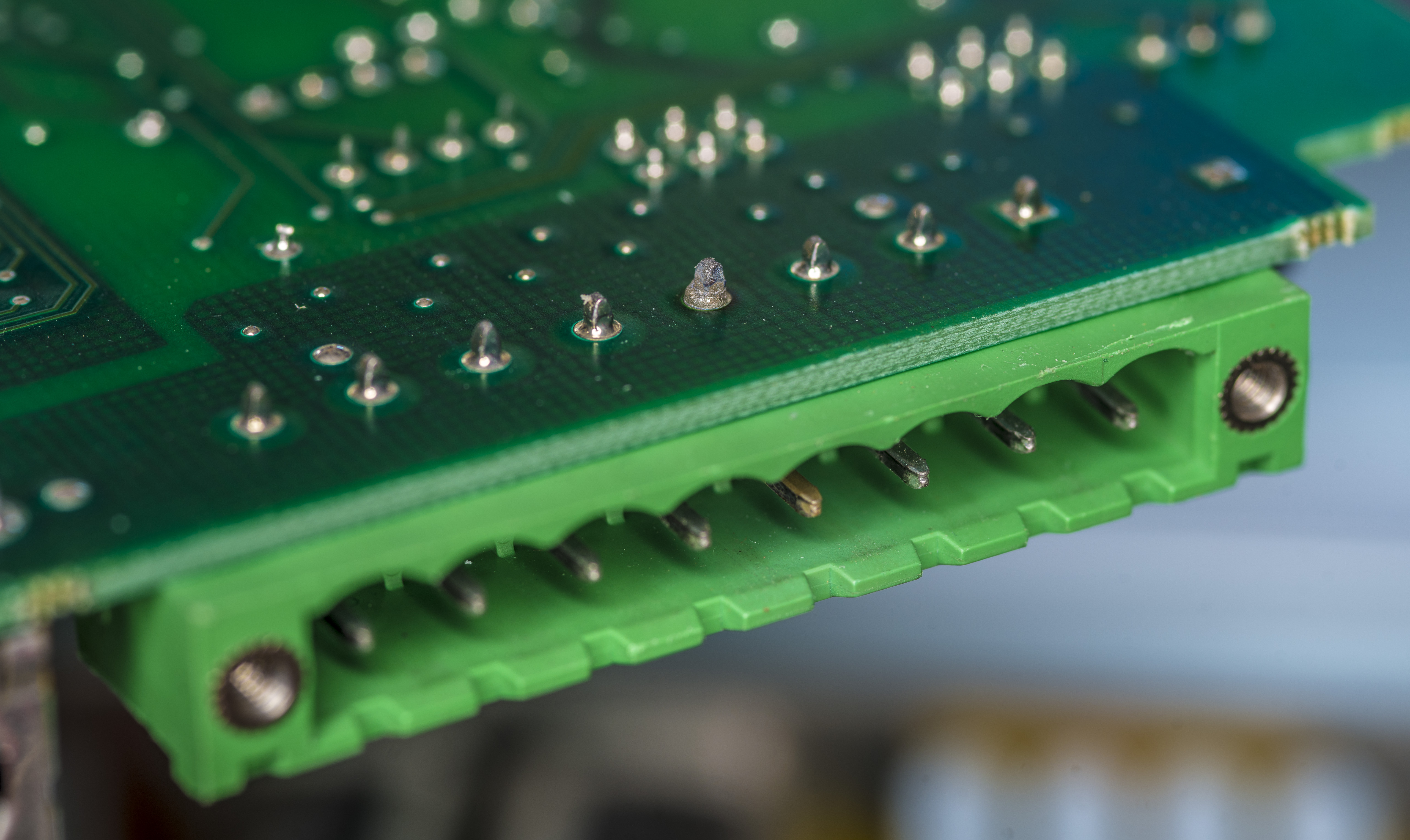
After cleaning pin and resoldering jump wire functionality of the instrument was restored.

Also terminal block connector will be replaced shortly to new one.
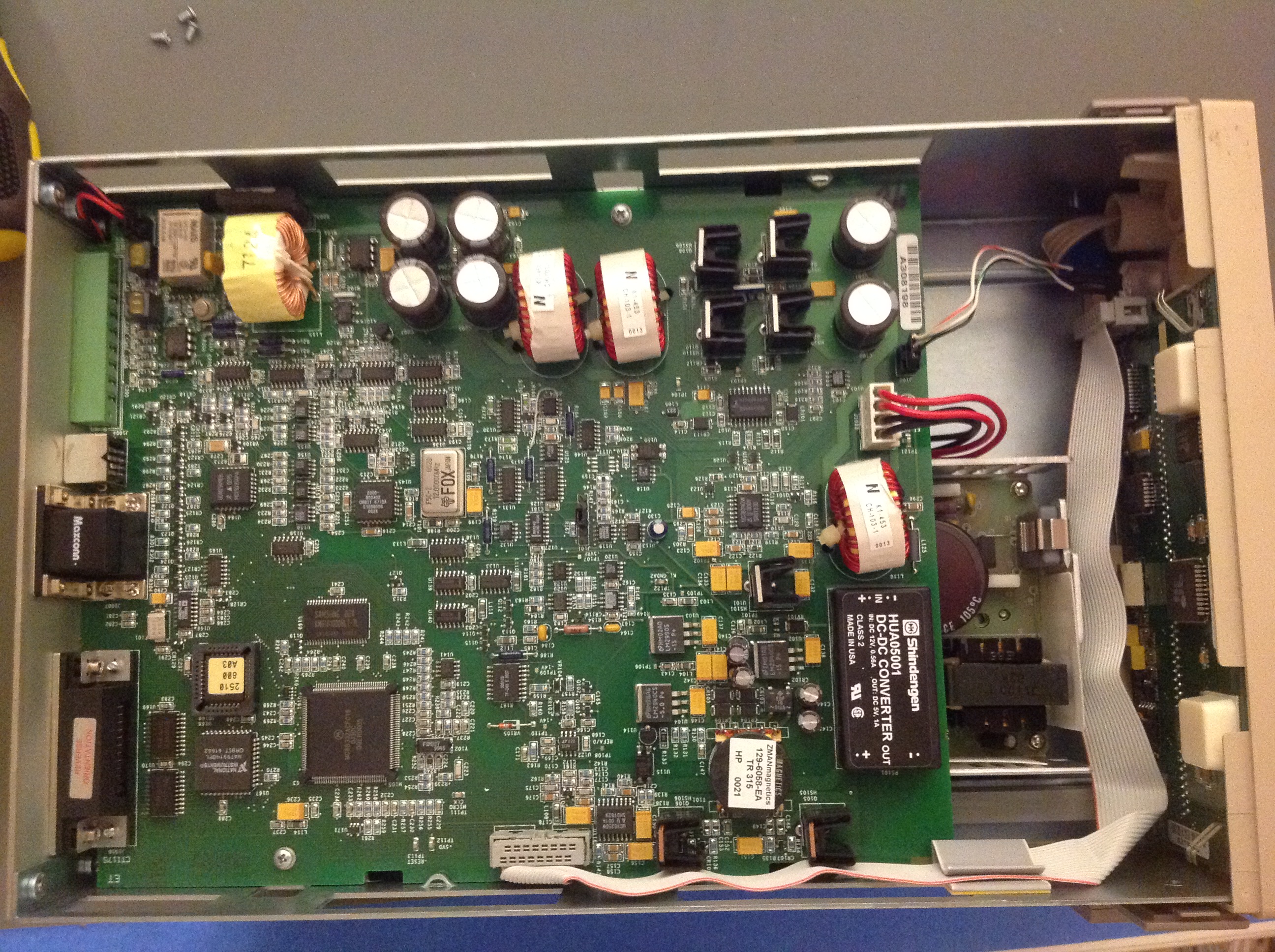
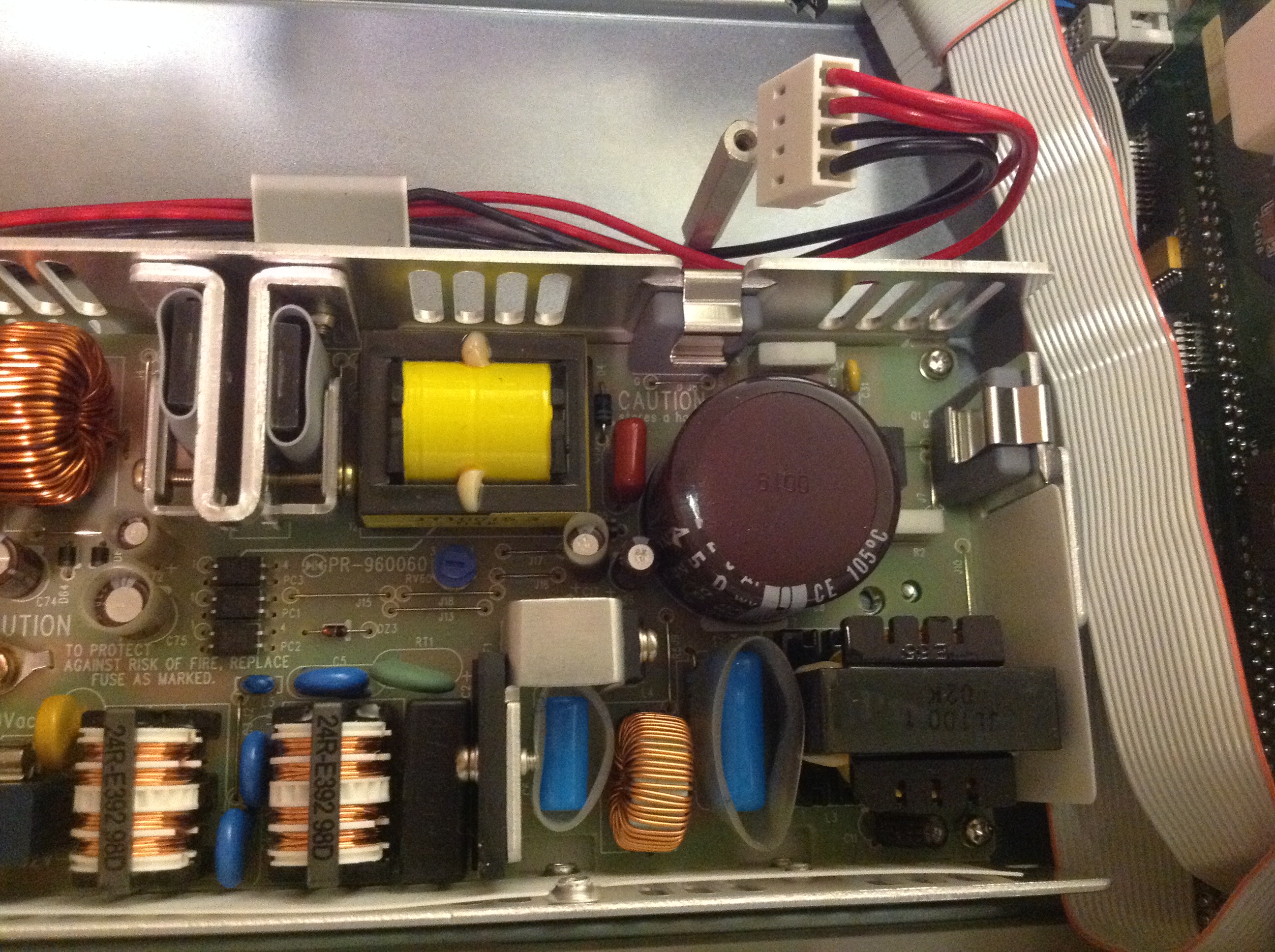
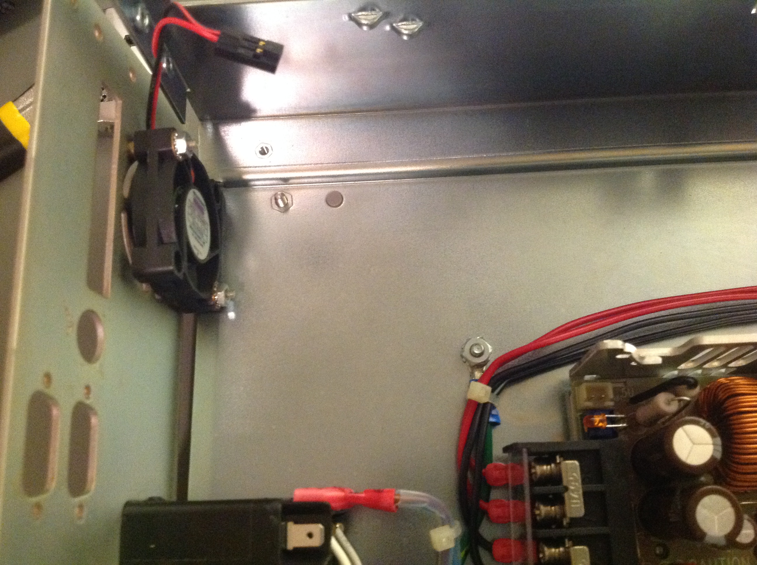
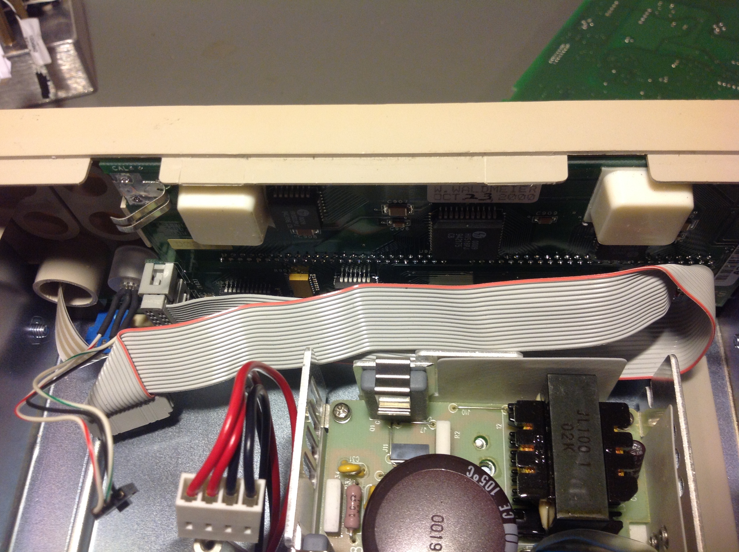
Here are also additional photos of K2510 mainboard, top and bottom side.
Other user’s units
One of readers who own Model 2510 too was kind to share his unit internal photos.


Options and extras
There is a secret menu available, similar to other Keithley gear, which allow to enable Autotune option for Model 2510.
This option come enabled in Model 2510-AT by default. Since hardware is same, it’s possible to transform Model 2510 into 2510-AT with simple steps as below:
1. Ensure unit is powered off.
2. Press and hold gray button "T" and button "CONFIG" and power on unit
3. Secret menu available now in MENU/GENERAL/SECRET
4. Navigate to AUTOTUNE item
5. Enable Autotune option
6. Unit will automatically reboot, showing Model 2510-AT now.
Projects like this are born from passion and a desire to share how things work. Education is the foundation of a healthy society - especially important in today's volatile world. xDevs began as a personal project notepad in Kherson, Ukraine back in 2008 and has grown with support of passionate readers just like you. There are no (and never will be) any ads, sponsors or shareholders behind xDevs.com, just a commitment to inspire and help learning. If you are in a position to help others like us, please consider supporting xDevs.com’s home-country Ukraine in its defense of freedom to speak, freedom to live in peace and freedom to choose their way. You can use official site to support Ukraine – United24 or Help99. Every cent counts.
Modified: May 10, 2026, 10:49 a.m.
References
- Optimizing TEC PID Coefficients Automatically with the Model 2510-AT
- Models 2510 and 2510-AT Service manual, Rev.D
- Keithley Model 2510 Firmware S-file, Version A11
- Keithley Model 2510 product page
- EEVBlog : Repair thread
- Documentation and firmwares
- Keithley forum : 2510-AT information
- TSP: Keithley 2510 repair and experiment demonstration