Contents
- Intro
- Disclaimer
- Manuals
- Teardown
- Repair
- Firmware
- Calibration
- Removing yellow front panel tint
- Performance test
- Conclusion
Intro
If phrase “One can’t has enough DMMs” is about you, then you might like getting broken DMMs in hope of fixing them. It’s true for us, and this time it’s another piece of Keithley gear, old but not obsolete, 8½-digit precision Model 2002 multimeter from Keithley, manufactured back in 1994.
Much younger unit was already reviewed more than two years ago, so be sure to check that article to refresh memory. That meter is still working perfectly fine and is in daily use 24/7, so I did not wanted to risk damaging it by experimenting with internal circuits and such. Hence this older dead Model 2002 will come handy for more intrusive work and ideas.
Precision 6ppm(DCV) accurate Model 2002 is still officially available on new Tektronix website (Keithley is now part of Tek/Danaher). Product page features 2002 for base MSRP $6530 USD. It is still one of few 8½-digit DMMs on market, just like 20’year old HP/Agilent/Keysight 3458A.
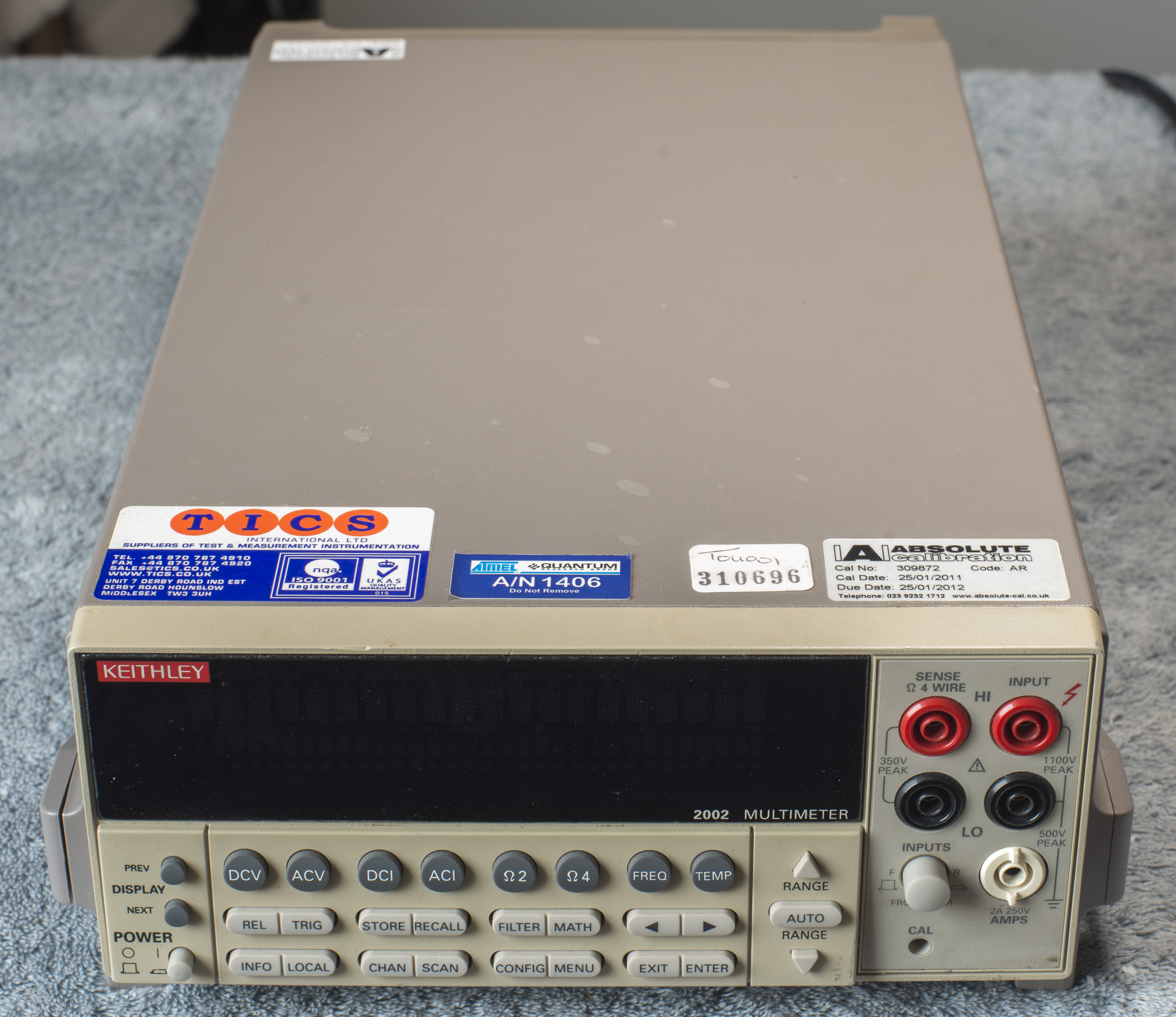
Instrument came in one piece, with all components, covers and boards, in as-is/parts condition.
Disclaimer
Redistribution and use of this article or any files referenced in it, in source and binary forms, with or without modification, are permitted provided that the following conditions are met:
- Redistribution of article must retain the above copyright notice, this list of conditions, link to this page (https://xdevs.com/fix/kei2002_u2/) and the following disclaimer.
- Redistribution of files in binary form must reproduce the above copyright notice, this list of conditions, link to this page (https://xdevs.com/fix/kei2002_u2/), and the following disclaimer in the documentation and/or other materials provided with the distribution, for example Readme file.
All information posted here is hosted just for education purposes and provided AS IS. In no event shall the author, xDevs.com site, or any other 3rd party, including Keithley Instruments or Tektronix be liable for any special, direct, indirect, or consequential damages or any damages whatsoever resulting from loss of use, data or profits, whether in an action of contract, negligence or other action, arising out of or in connection with the use or performance of information published here.
If you willing to contribute or add your experience regarding any test instruments or provide any extra information, such as firmware dumps, internal photographs, you can do so following these simple instructions
Manuals
Here are available manuals from KI so far.
Model 2002 Calibration certificate example
Model 2002 Repair manual, Rev B
Model 2002 User’s Manual, Rev E, Feb 2009
Model 2002 Getting Started Manual, Rev A, May 1994
Model 2002 Calibration Manual, Rev D, May 2004
Model 2002 Multimeter Specifications, Rev I, Nov 2009
As with all recent Keithley gear, schematics or detailed construction information is not available. Best we have is repair manual troubleshooting hints, self-test diagnostics description and part list (which is very helpful).
Teardown
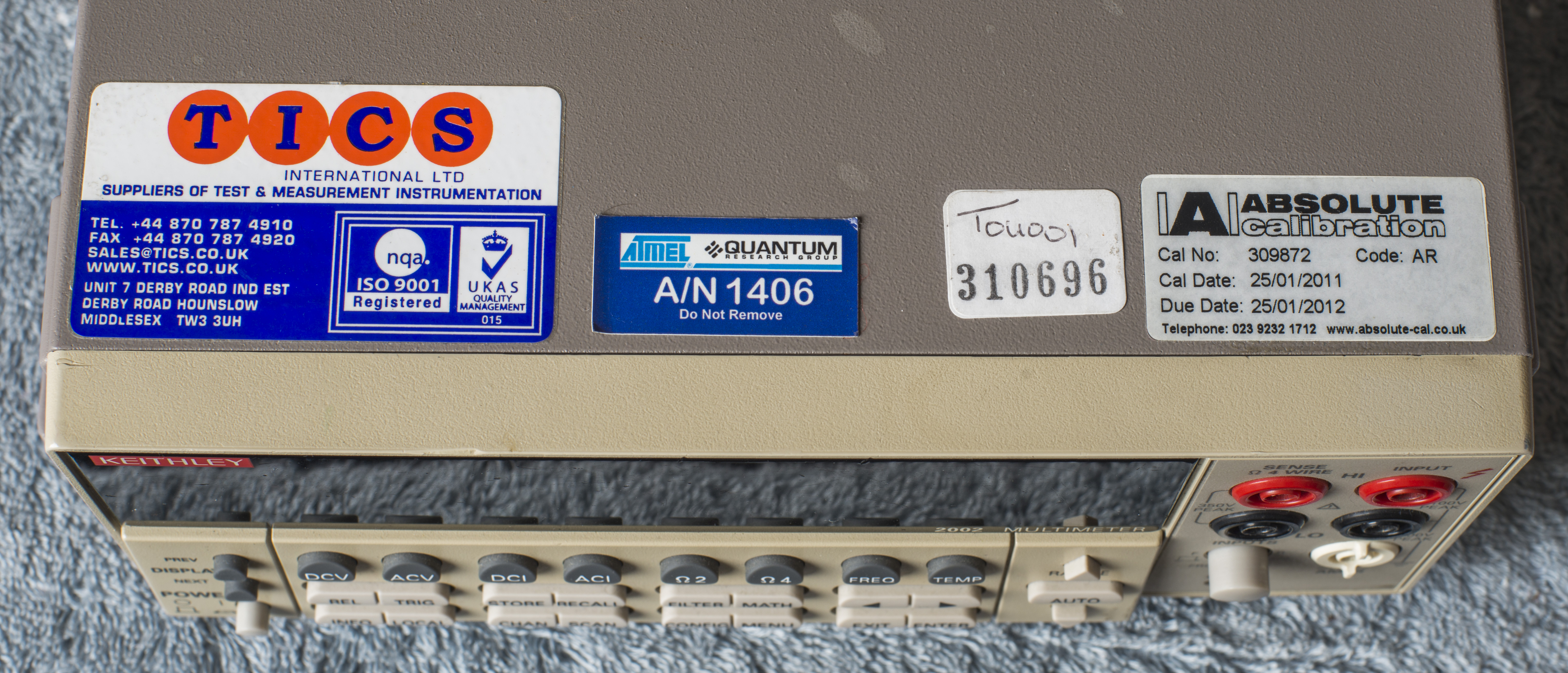
According to labels, unit was last calibrated in 2011, and was used in ATMEL labs. Will be interesting to see if unit still in spec after repair.
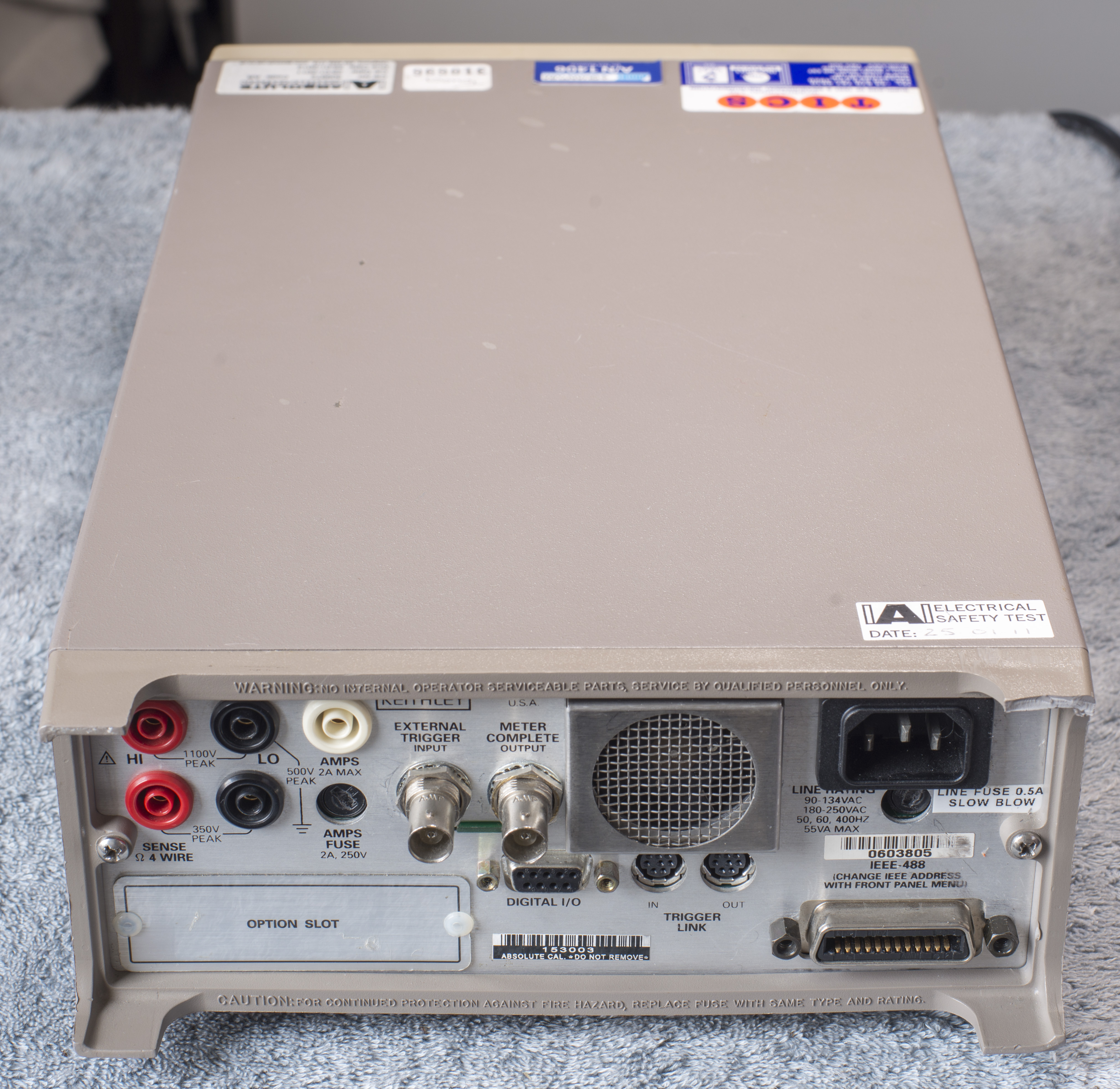
Covers removed
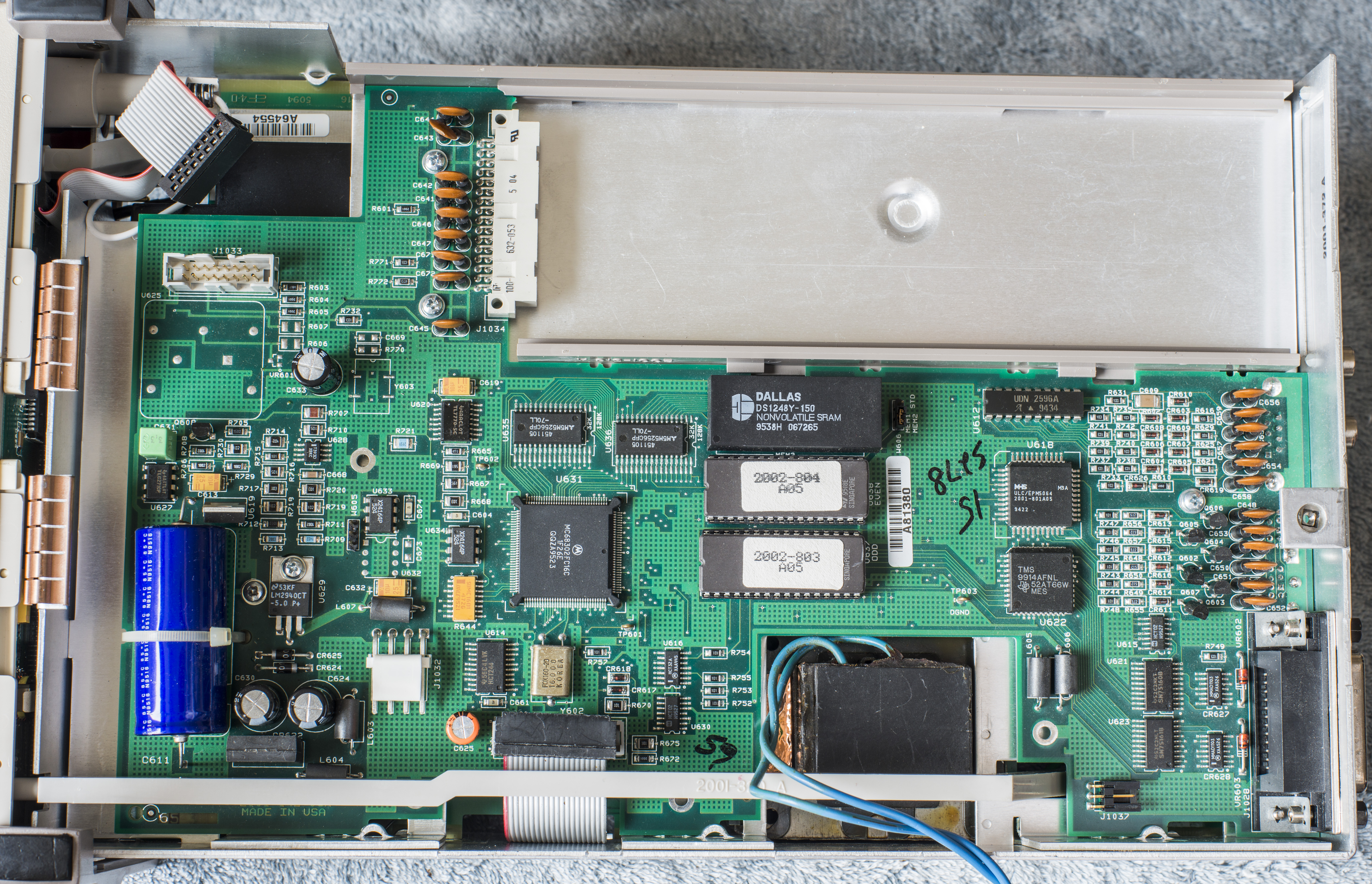
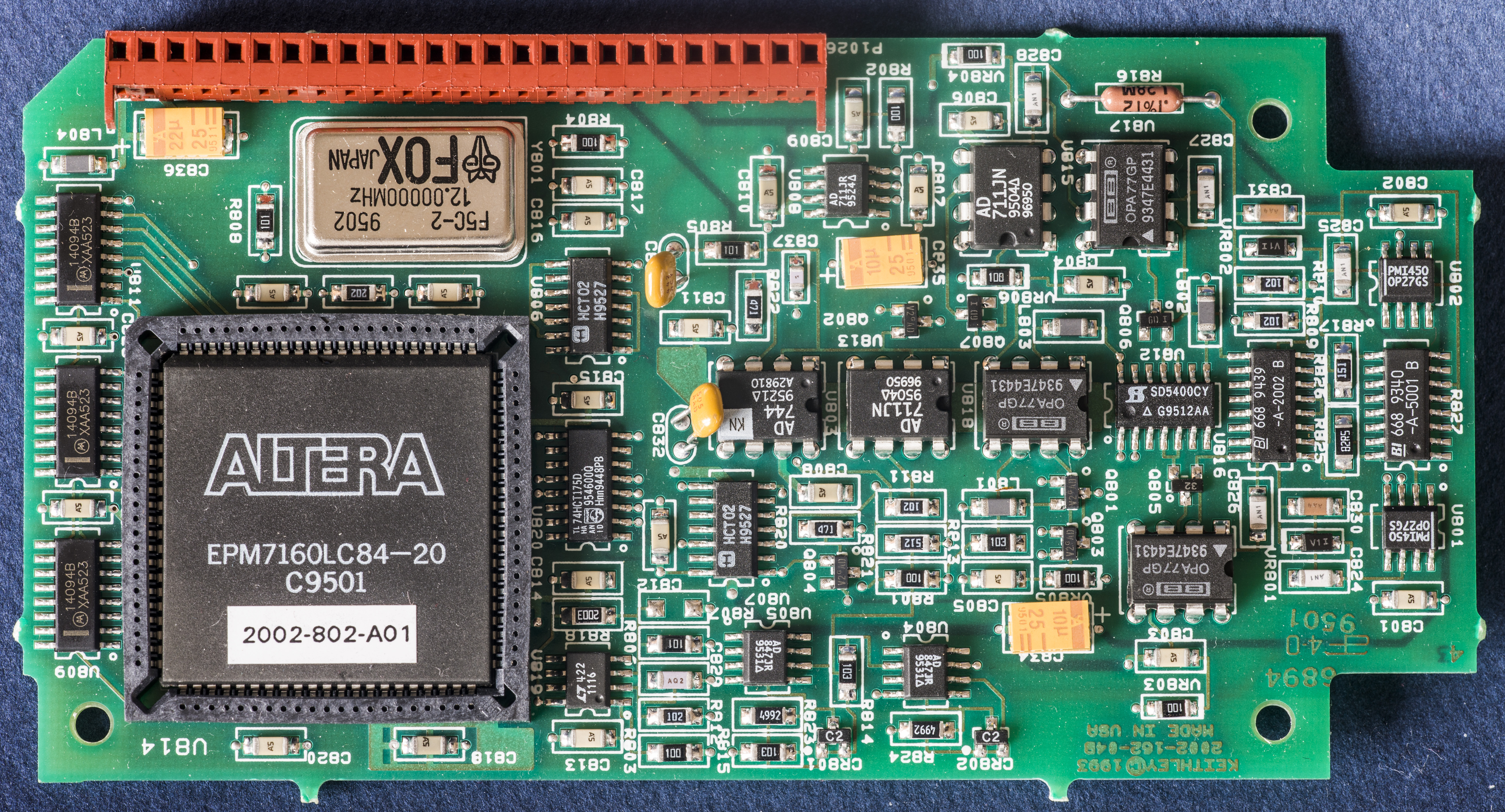
Close up on digital board processor, ROMs and RAMs.

Firmware is old A05, but since both ROMs are UV eraseable, it’s easy to reprogram it to latest version I have, A10. It will be done after complete repair.
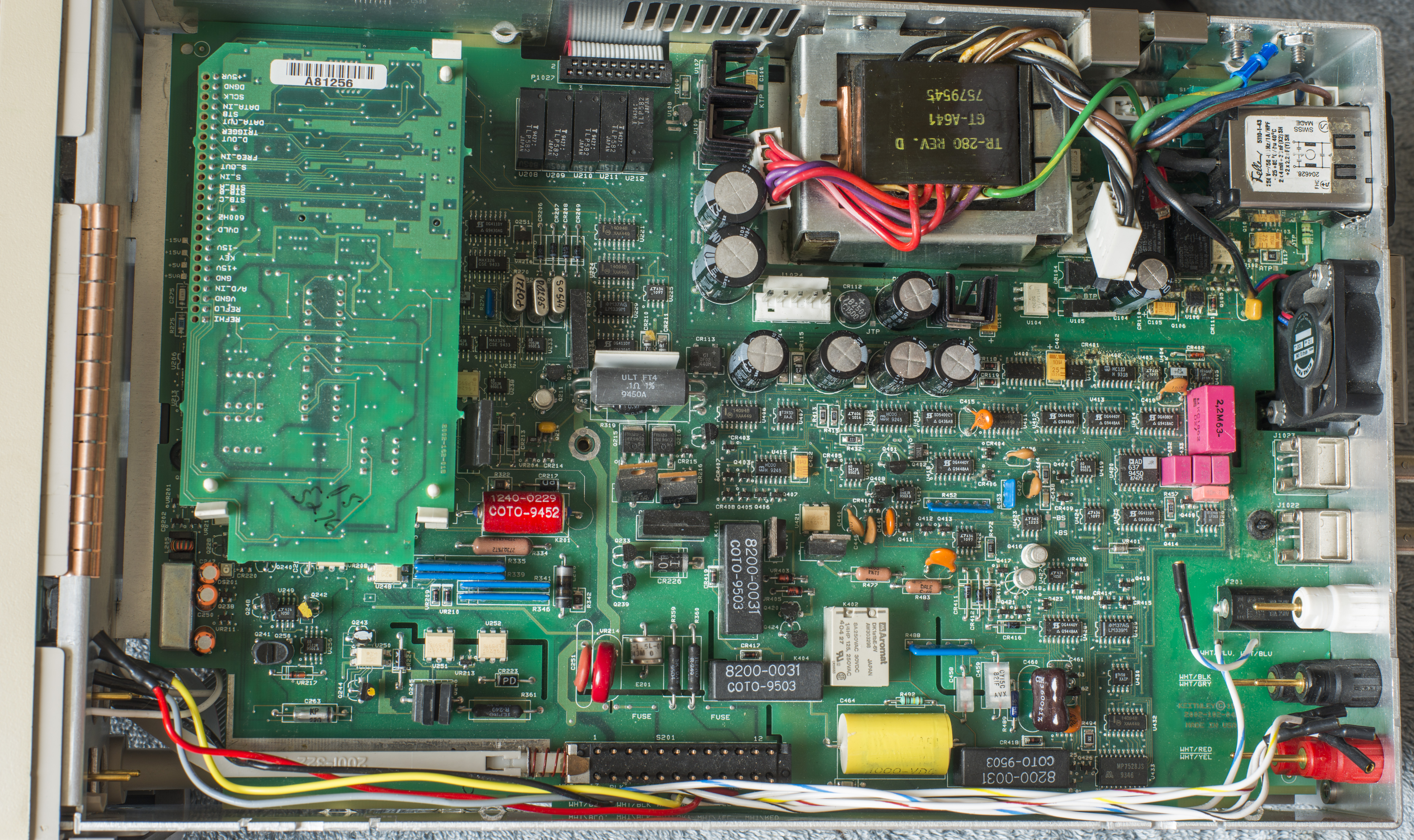
A/D board:
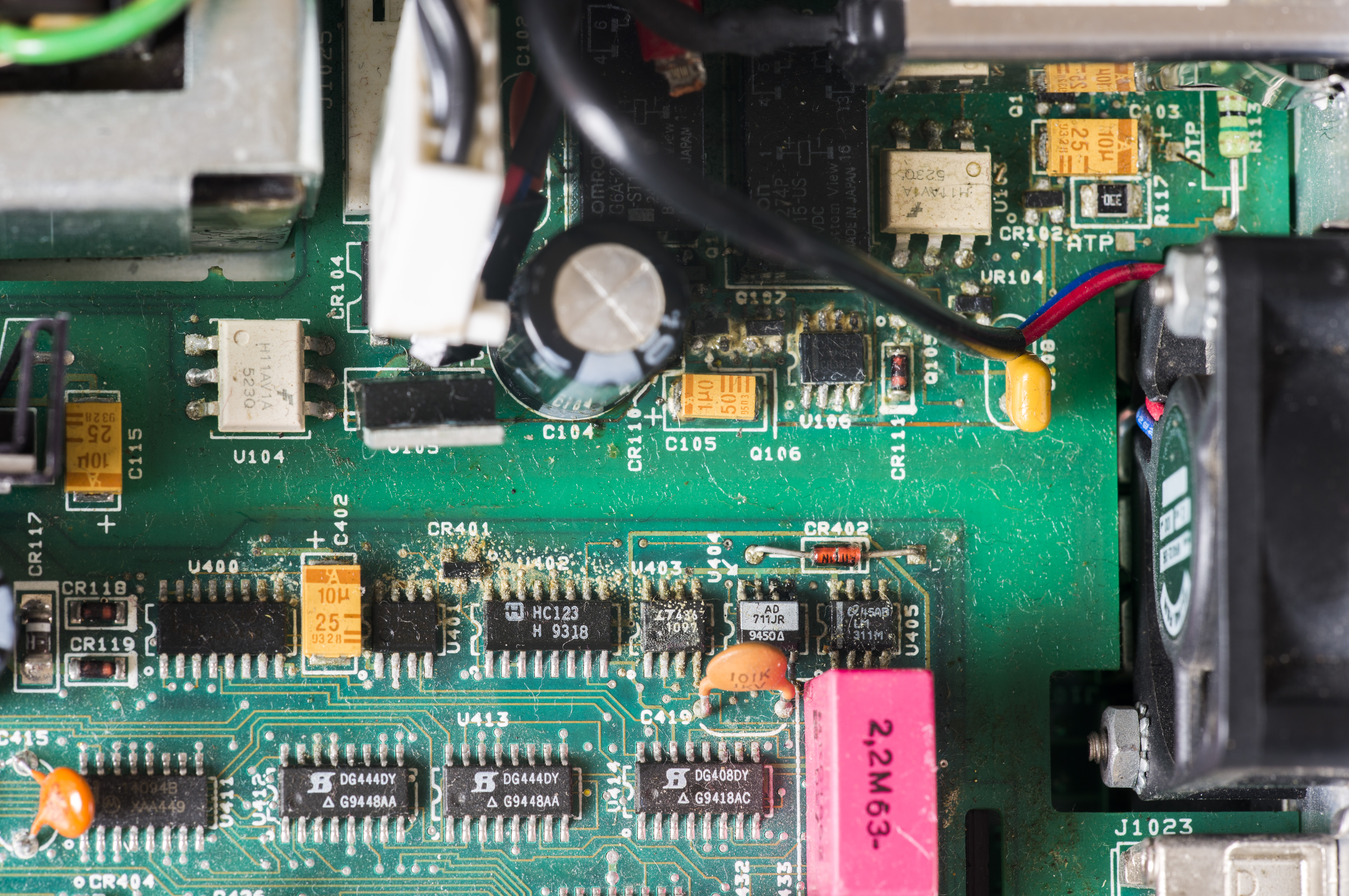
Analog board, 2002-101, Revision D, while our 2007 year unit have Revision E board.
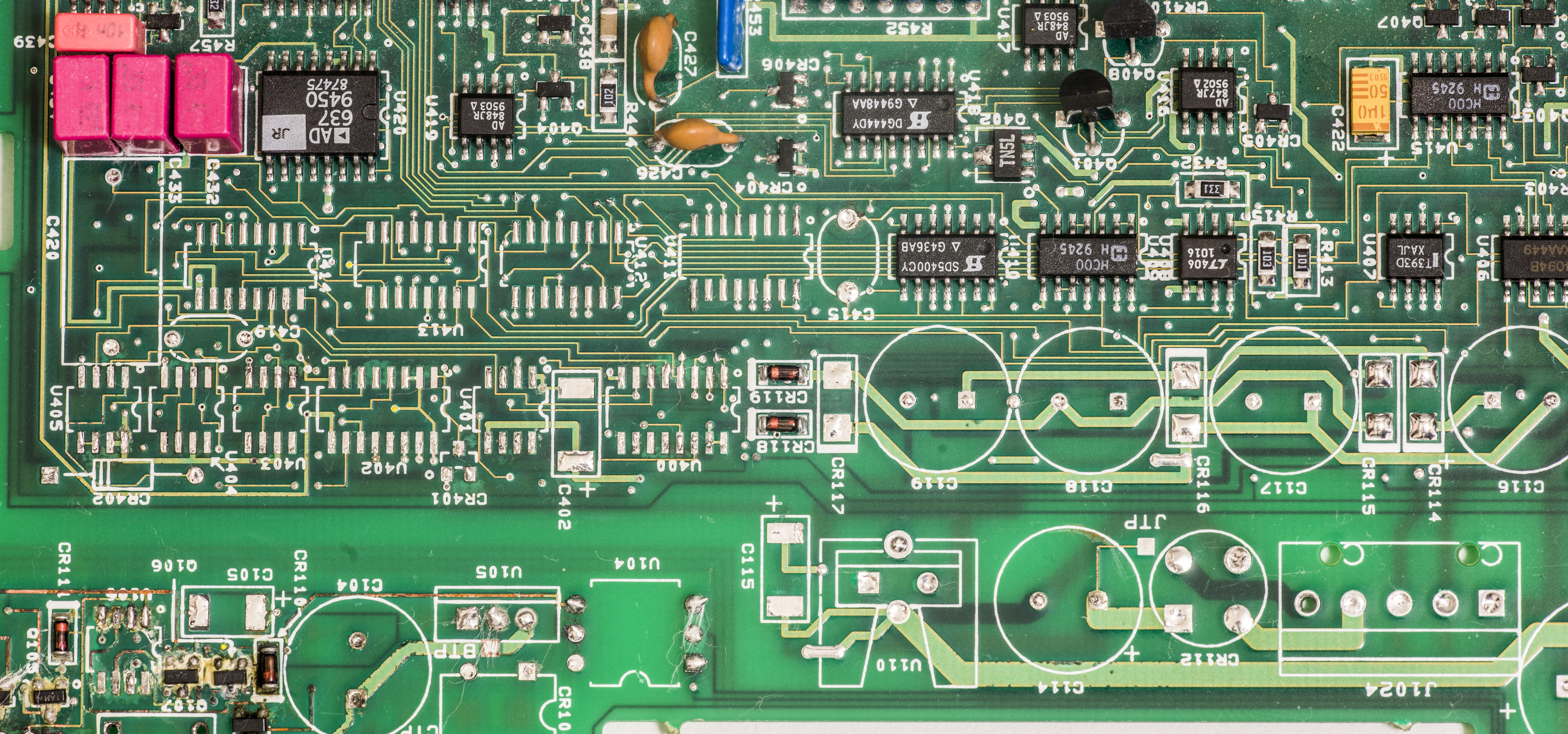
Voltage reference, Ohm current sense and measurement sections, interface to digital board, all seem to be nice and intact. You can see Linear LTZ1000A ultra-stable main voltage reference, covered by black caps from top and bottom, and capacitive ratio blocks based on Linear LTC1043, which are taking 7V from reference and generate secondary references used in meter. One of these is doubled 14V for resistance function operation. Second is divide by 4 to get ~1.8V for low ranges ADC conversions. These blocks have very low temperature coefficient and are quite stable blocks.
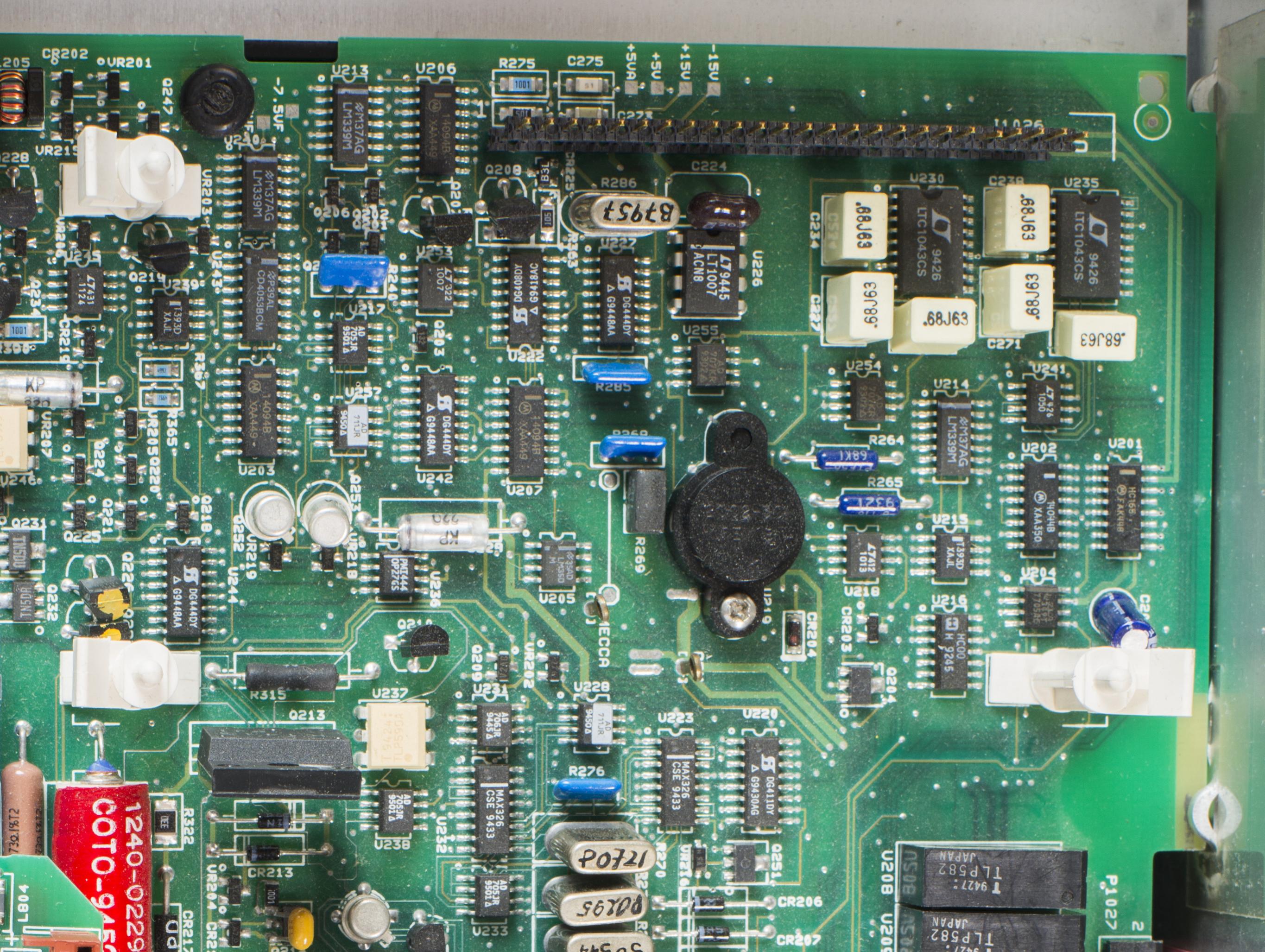
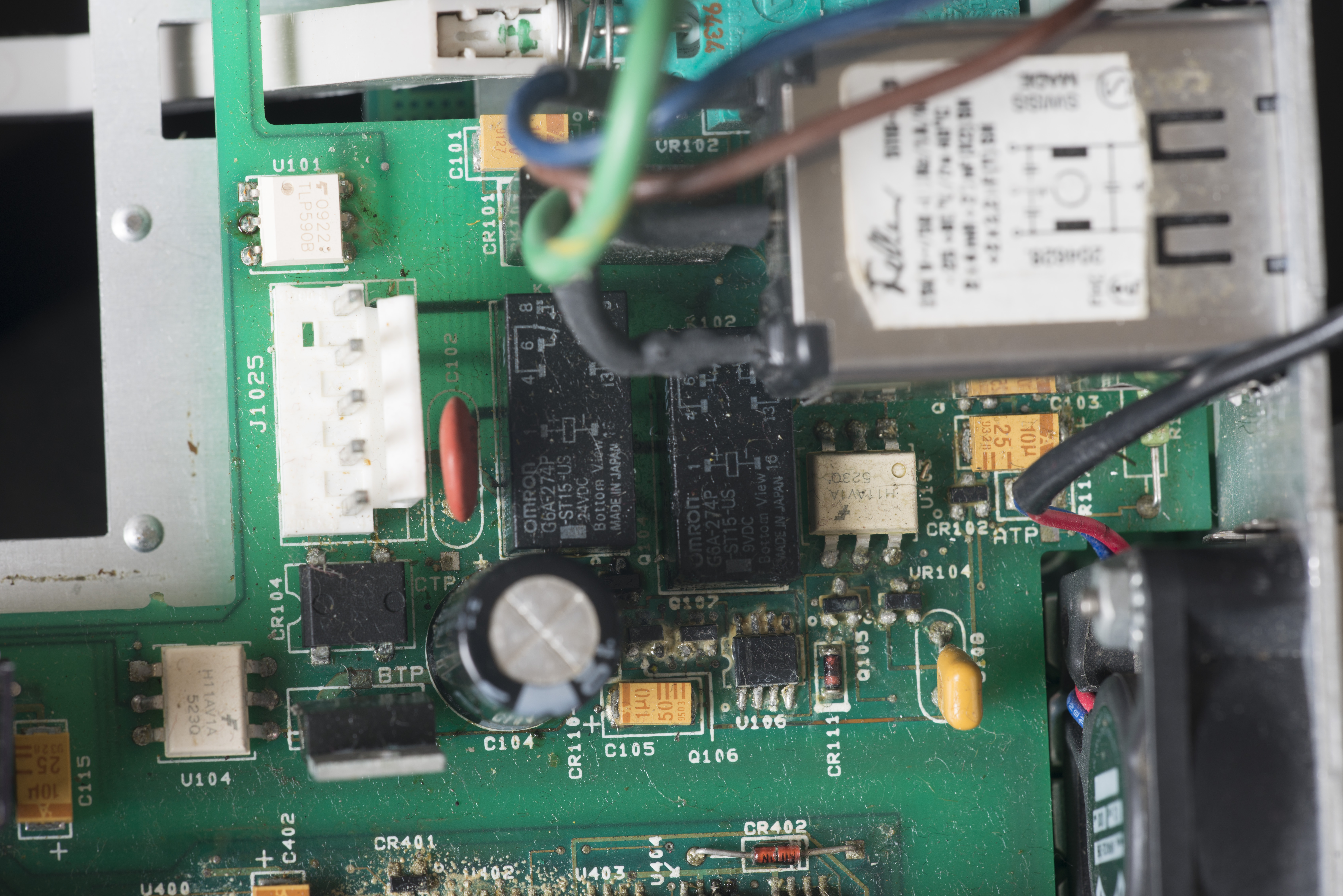
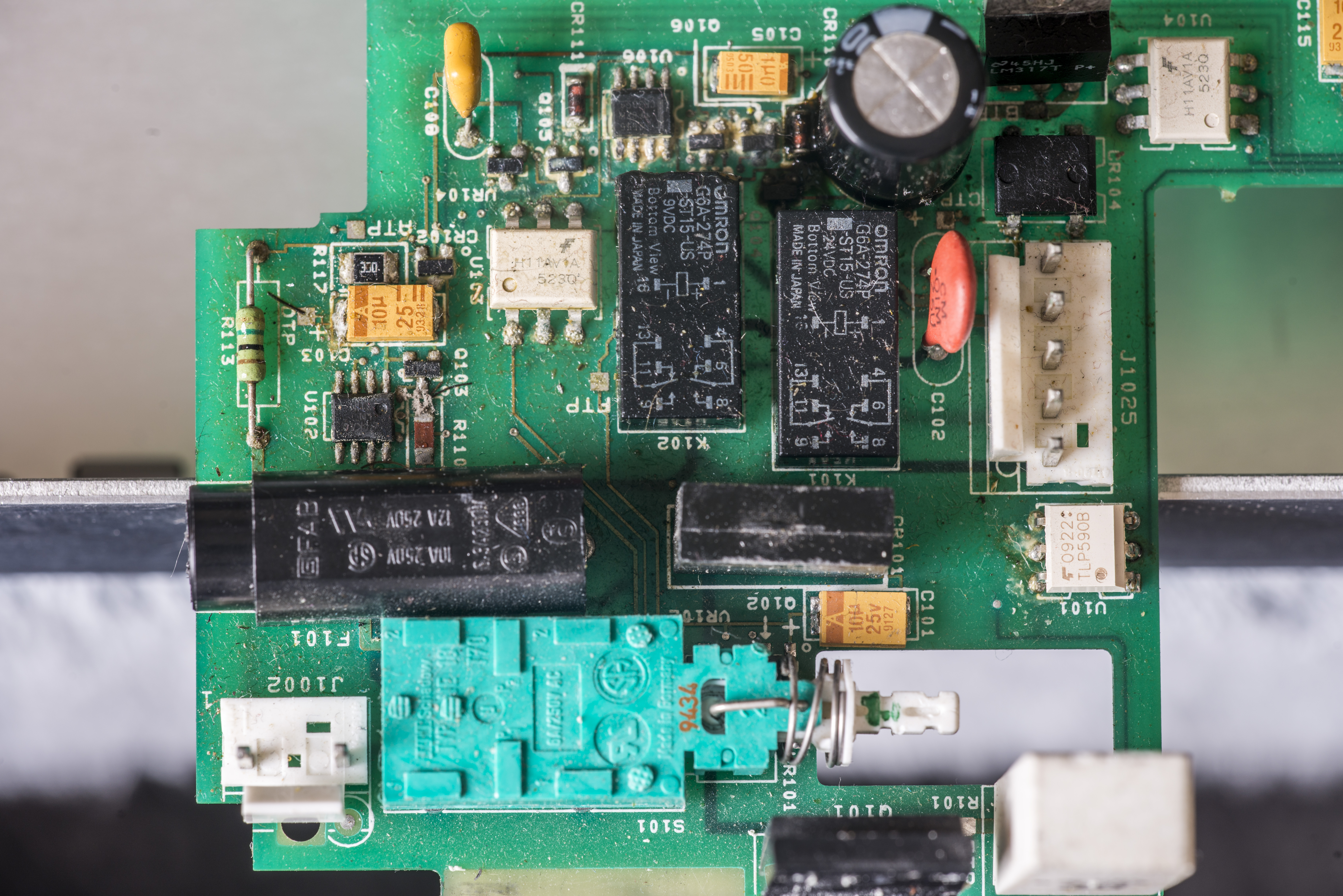
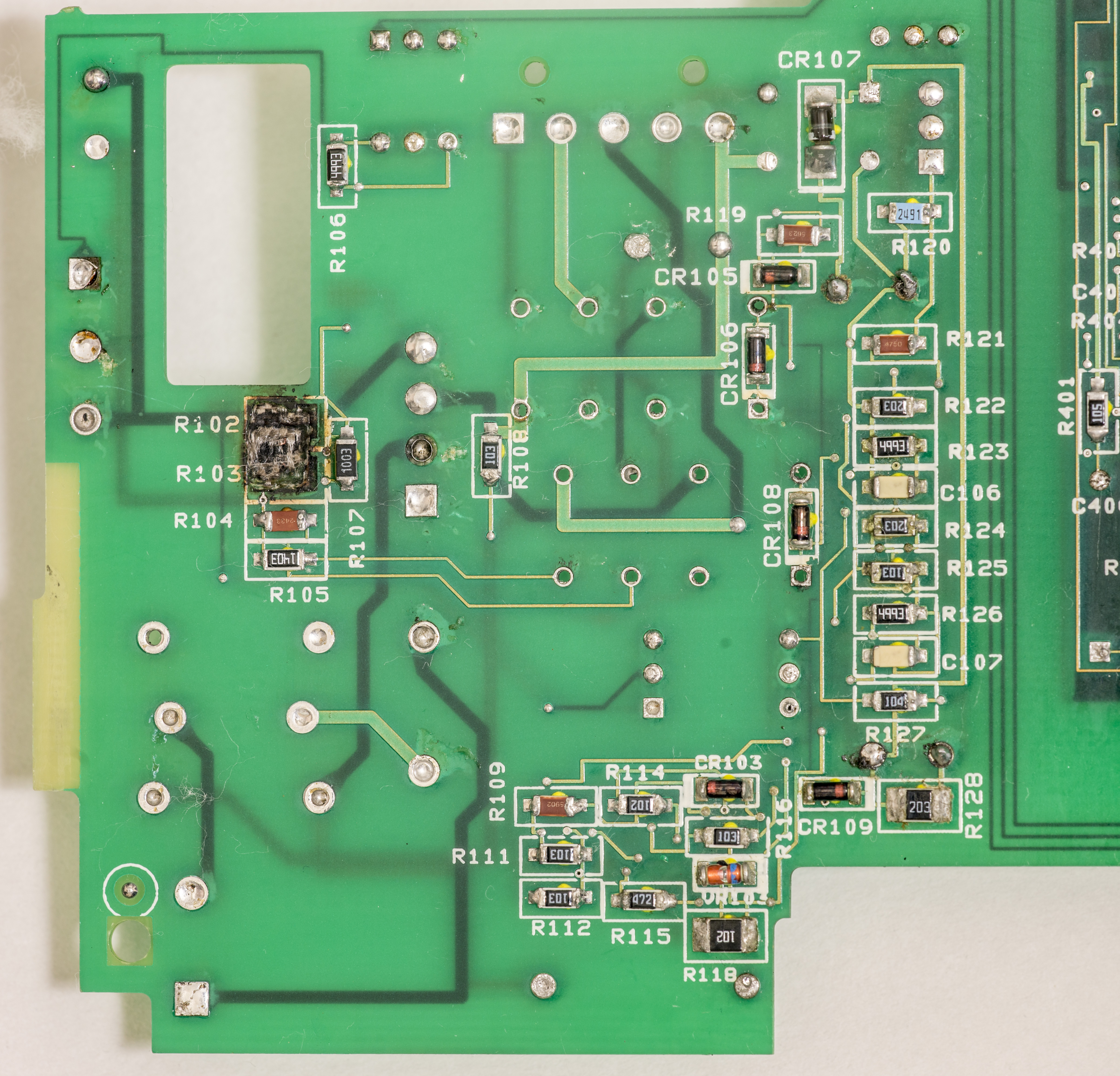
Not so much for earth referenced input circuitry, all covered in electrolyte gunk.


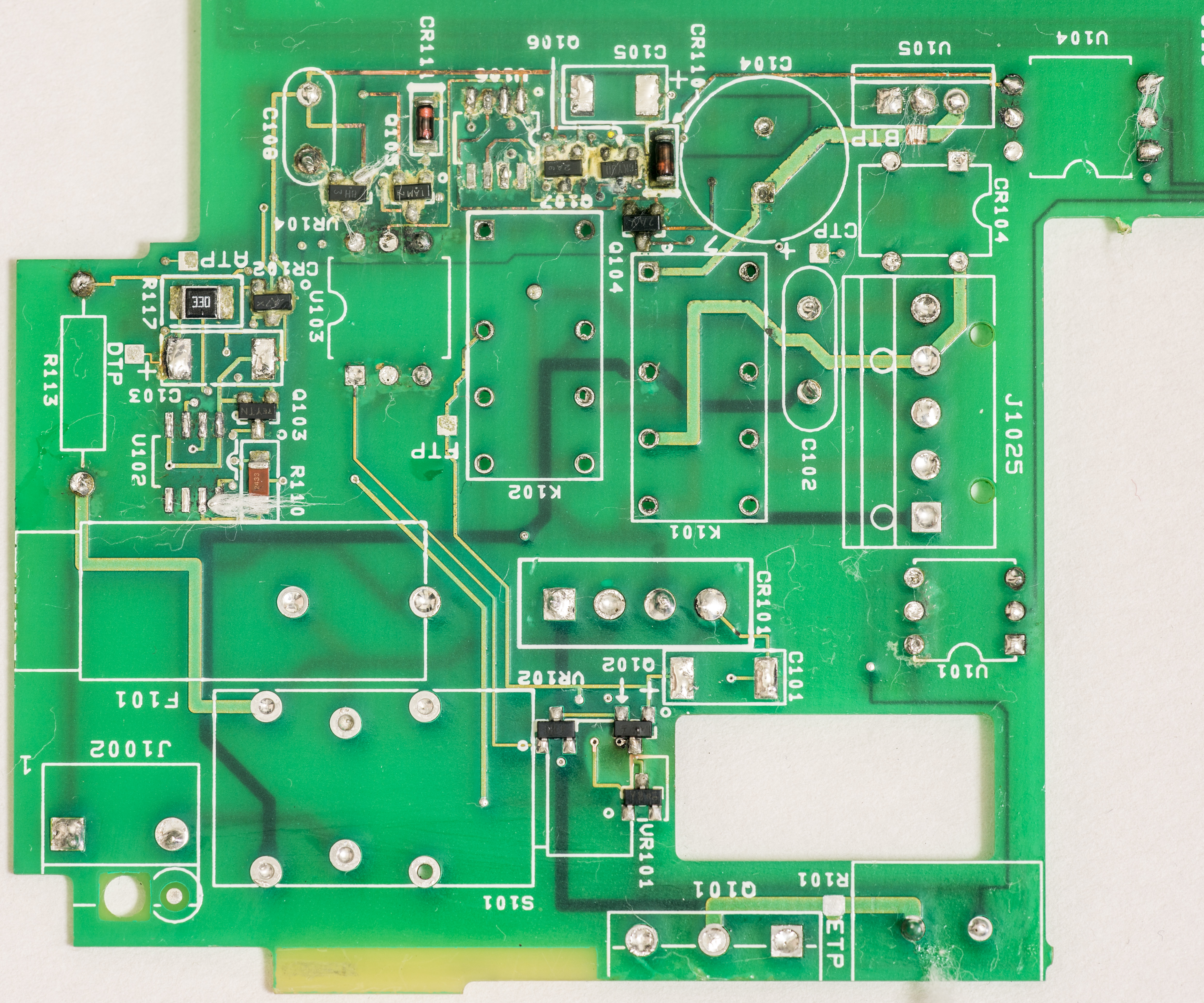
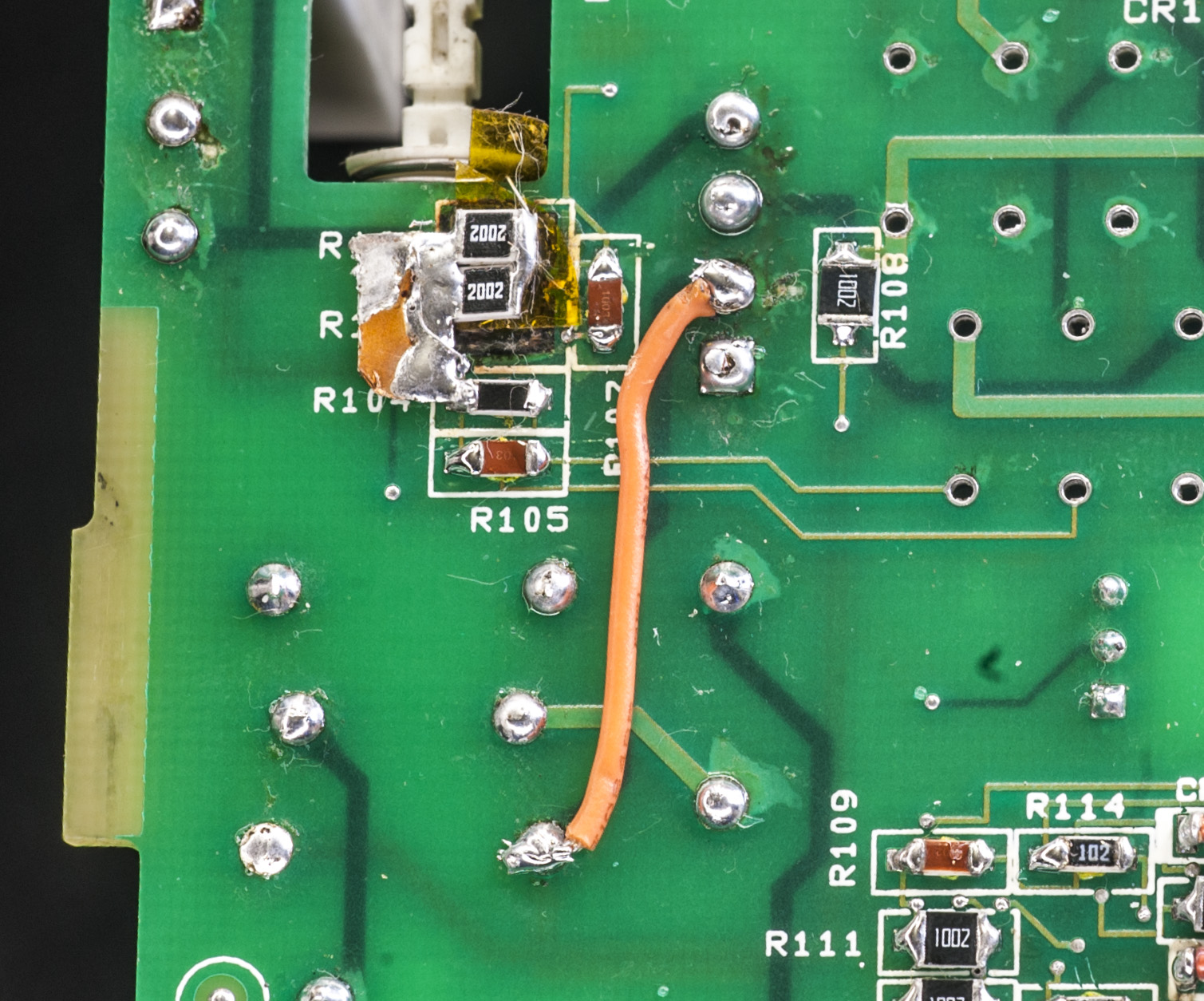
All this disaster caused few components and 20KΩ 1210 resistors on bottom PCB surface to explode.

Repair
Day 1, cleaning
First job would be to remove all electrolyte leaked from C104 and bad parts from the analog board and get it ready for repairs. Since electrolyte leak was so severe, usual wiping with alcohol will do nothing here, so all parts in affected area must be desoldered, to allow thorough PCB cleaning from both sides. Cheap and common components, such as NE555, capacitors, resistors will be replaced with brand new items, while custom parts such as 6-pole power switch, polycarbonate 2.2uF cap, connectors will be cleaned, checked and reinstalled back into board.
It’s better to replace even working parts, as electrolyte likely soaked into plastic, possibly causing future failures. It’s not worth saving pennies in such case as this.
First day all thru-hole parts on earth-referenced circuitry removed, started cleaning PCB.
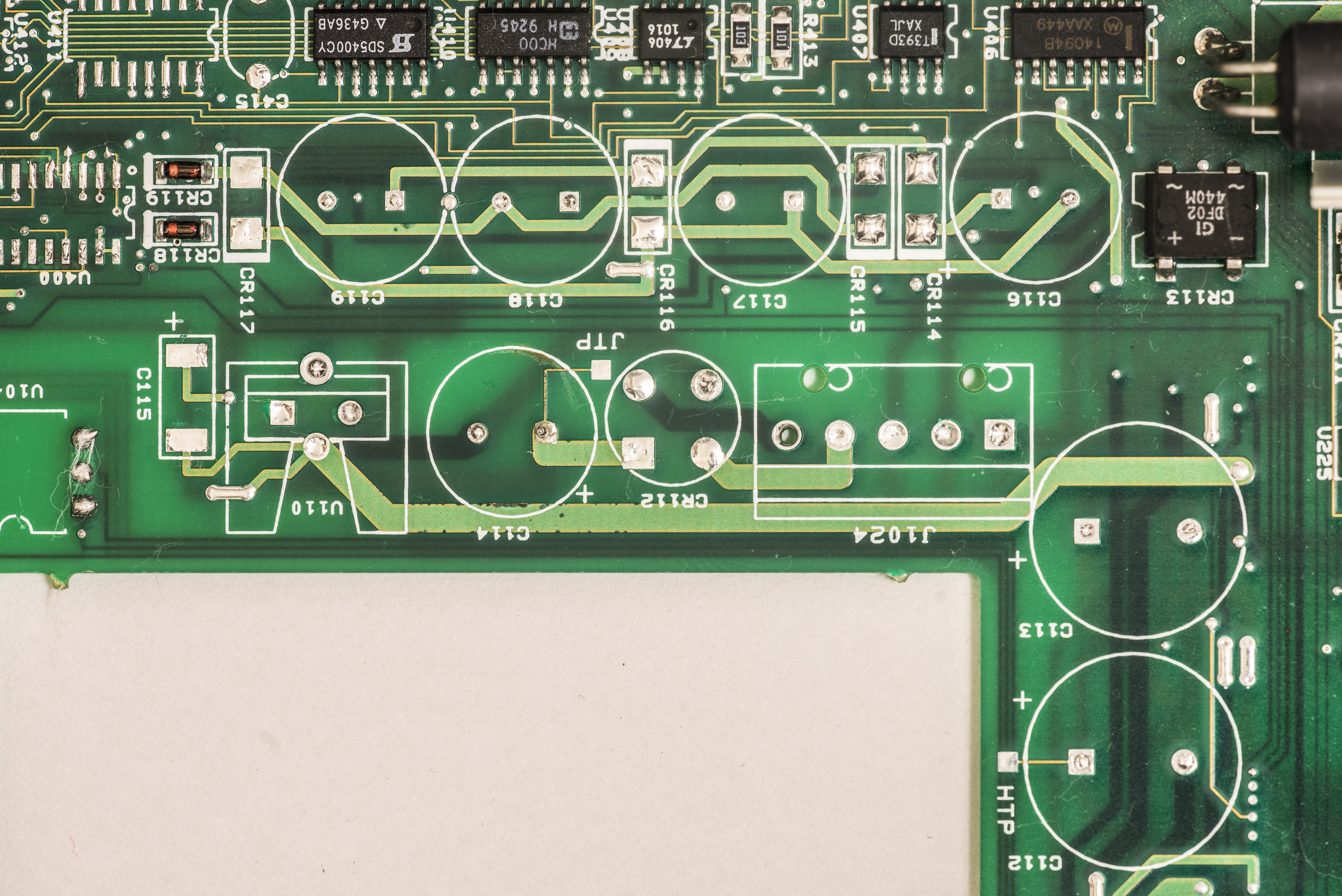
On secondary side, seem not much damage occur, just a bit of electrolyte leak, mainly from C114. All capacitors will be replaced to brand new +125°C rated ones from Chemicon.
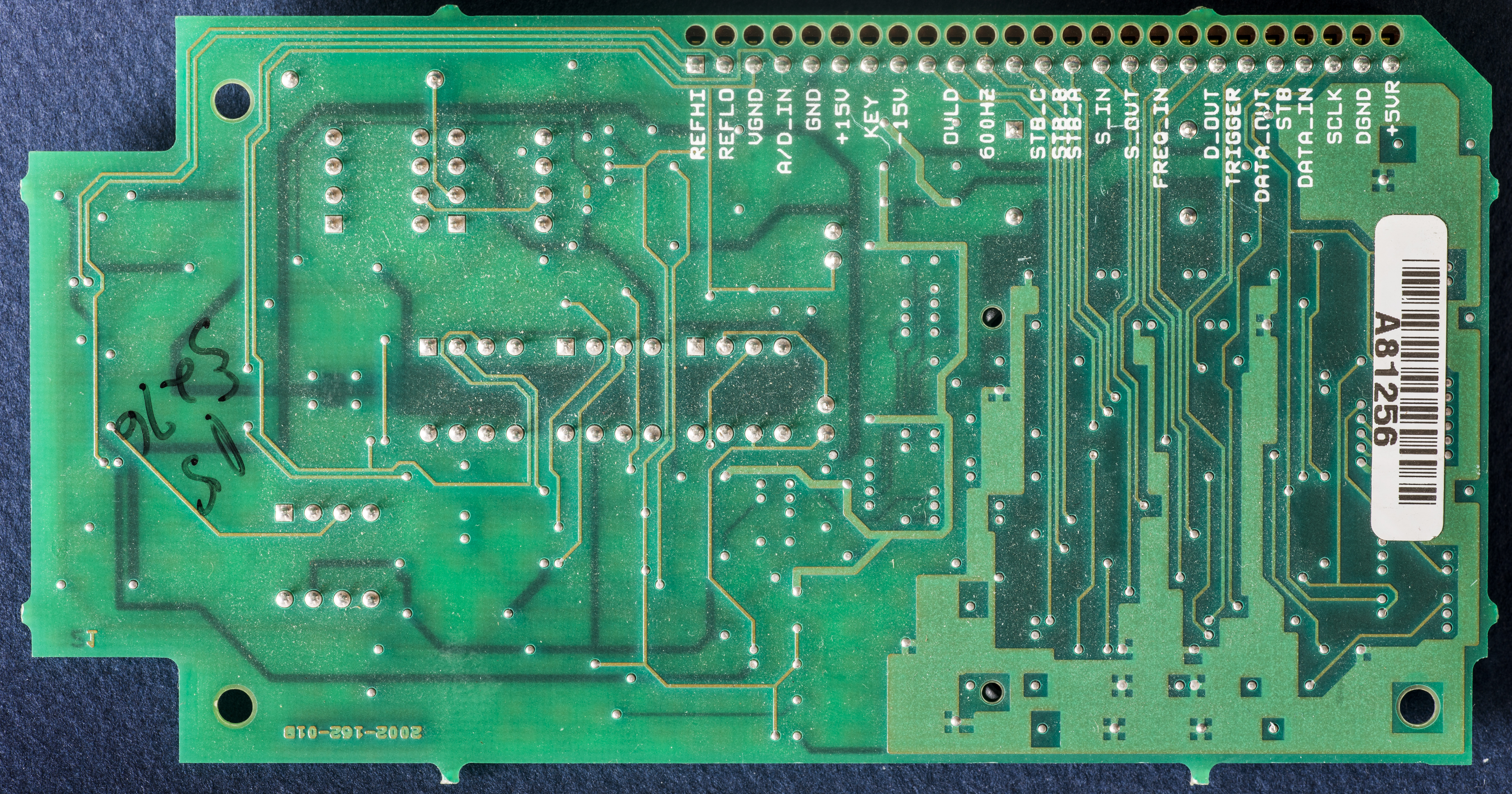
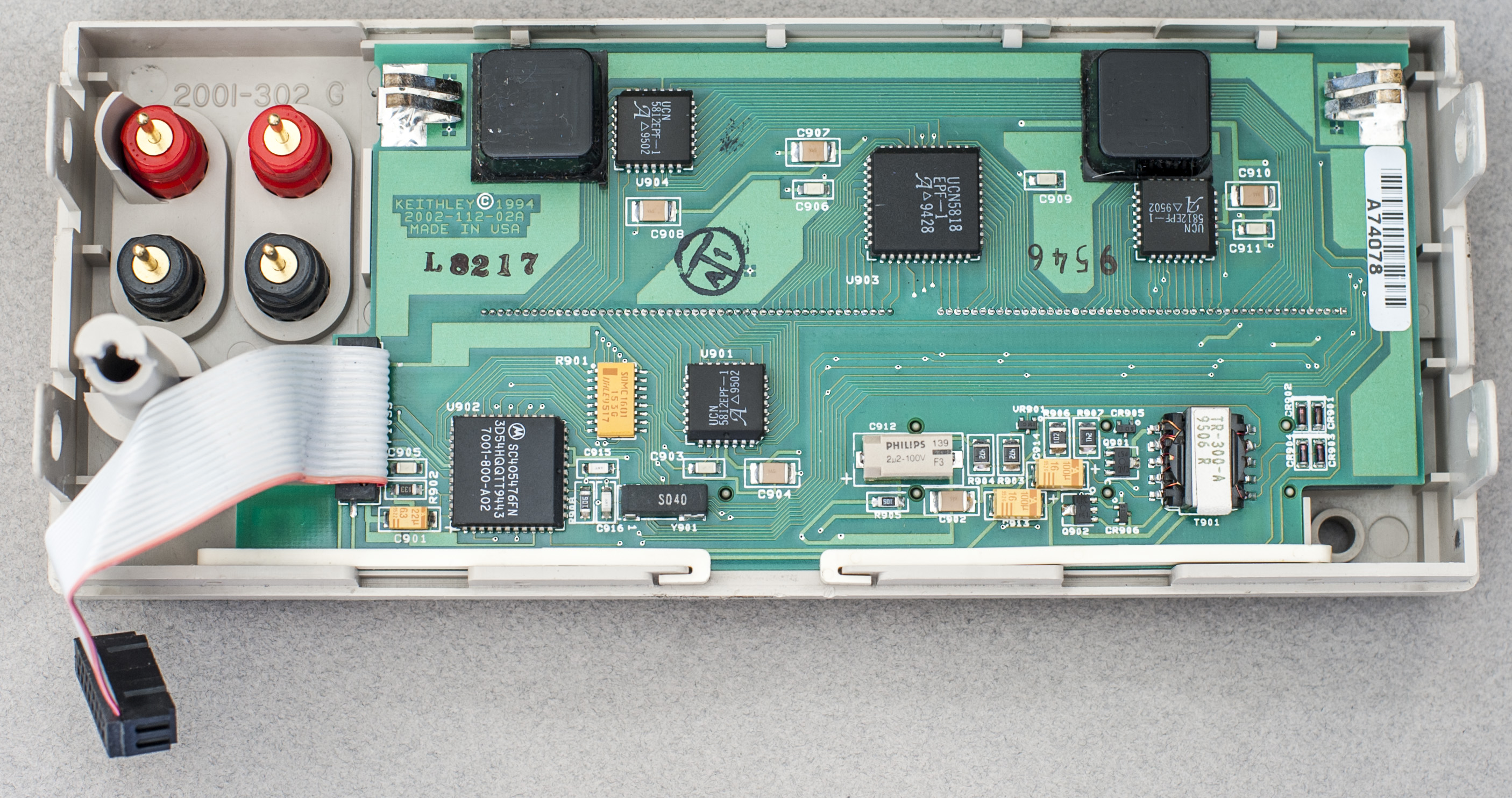
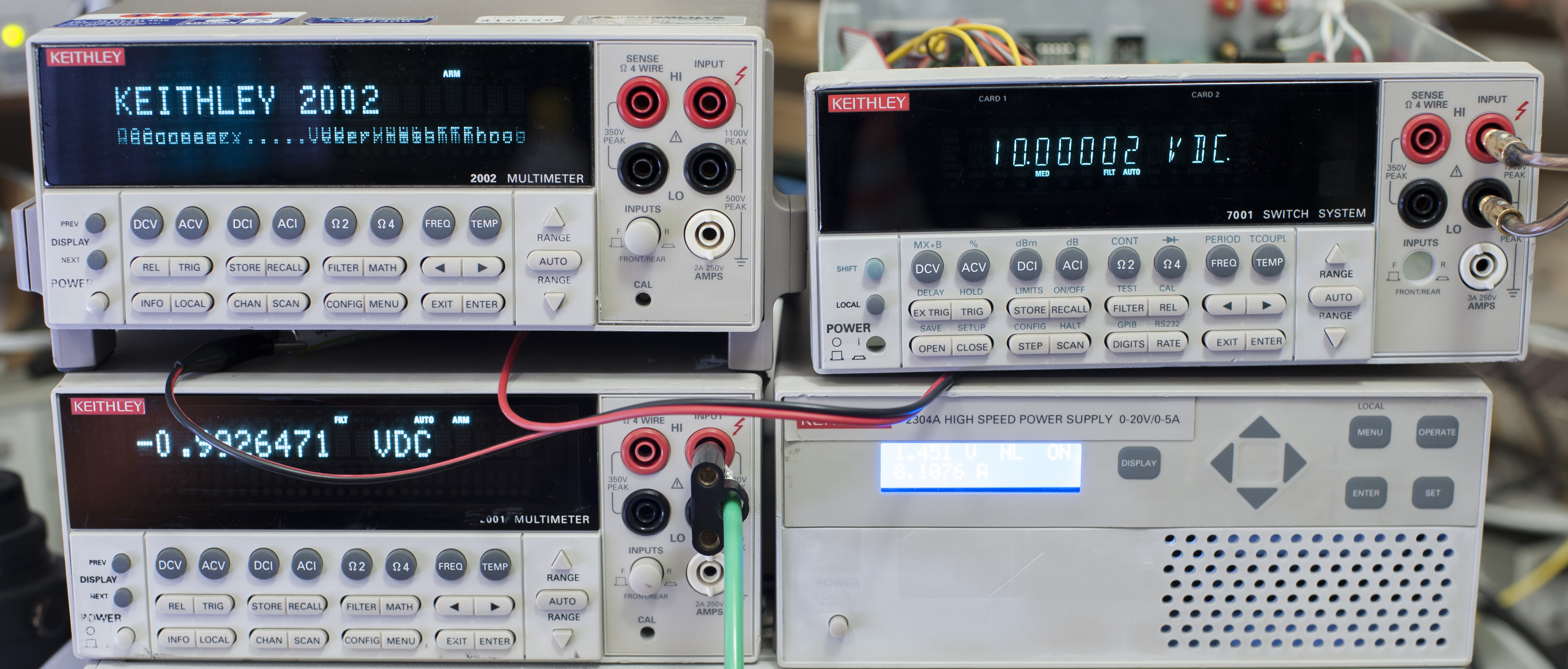
As a side note, digital board 2001-162 Rev.K was checked for proper operation, with help of external PSU Keithley 2304A providing 6.3VDC to power the board.
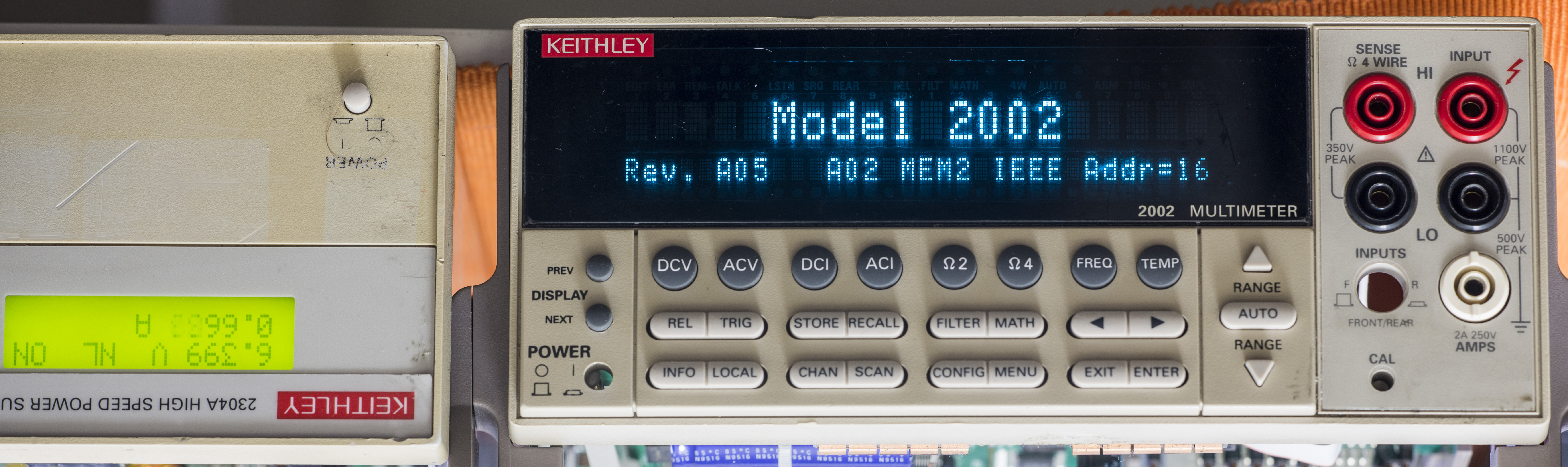
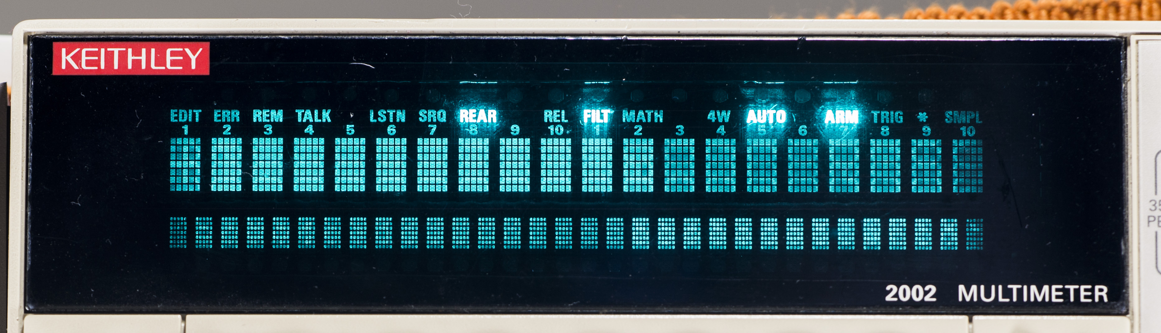
VFD screen is bit aged, but perfectly useable with all segments visible in normal conditions. It is same Noritake/Newheaven display DD-51 used in other instruments, such as Model 2001, 700x, 24xx/25xx/26xx series SMUs and so on.
Power transformer is checked as well, it’s working well in good Keithley 2001. This is a good news, as this is custom part, and would be likely expensive to replace from Tektronix/Keithley.
Day 2, more cleaning
Now all parts are removed, board is well cleaned with isopropyl alcohol. Time to check tracks and probably do some repairs to damaged via’s/tracks.

Time to put some components back onboard. Start from secondary side 1000µF 50V, 2200µF 25V, 2200µF 35V and 470µF 63V Low-ESR capacitors. All of them are brand new Chemi-con KMG and KZE series.

Rest of parts should arrive March 21, according to Digikey’s box tracking.
Initial check on components revealed that 470 Ω 10W cement resistor is also open. Glad I ordered replacement for it (7W only, but should be OK).
Day 3, soldering new components on analog board, testing
Well, actually it was a week between, till components arrive, but I was busy with other projects and did not touch this meter. So we will count it as third day here.

I used nice high-temperature rated for 2000hr life at +105°C, 1000µF 50V capacitor, Vishay 142RHS for replacement, that should give us a decade of life for this meter. It’s same 12.5 × 25mm size, so fits the spot nicely.
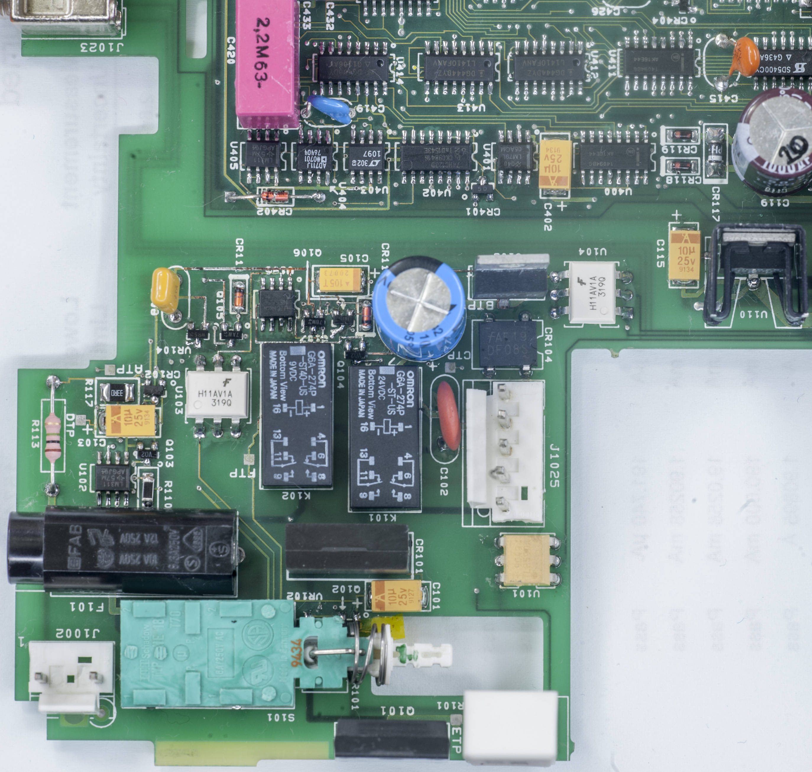
Mains switch, large MOSFET Q101, connectors for transformer and mains filter, fuse holder and LM317T regulator were checked, thoroughly cleaned in IPA and installed back on board. I also replaced nearby components on analog side, DG444DY, DG408DY switches, few 4094 shift registers, 79L05 regulator in SO8 package, AD711JR and LT1097 opamps. Original parts were likely to be okay, but I saw electrolyte residue on them, that can’t be good for leakage and specs, so better be safe than sorry and replace everything.

Every component in area affected by electrolyte was replaced, mostly with new parts, but some of resistors were taken from K2001 donor board. Some bad looking PCB vias were stitched thru with extra copper strand to ensure the connection. Same goes to few traces, which were eaten away by aggressive electrolyte.
After about 4 hours of easy but tedious work everything was placed back in, and ready for first “smoke test”. That means circuits were checked and rechecked, meter sitting open at table and first power on with finger on the power switch to cut power off if something releases magic smokes.
But the extra precautions were not necessary, and meter happily booted fine, no smoke or smell emitted. I tested voltages on analog board and they all were just in spec.
| Voltage rail | Spec | Measured | Condition |
|---|---|---|---|
| +15V analog | +15V | +14.985 VDC | PASS |
| -15V analog | -15V | -14.976 VDC | PASS |
| +5V digital | +5V | +4.987 VDC | PASS |
| +5V analog | +5V | +5.031 VDC | PASS |
| +BS | +38V | +38.841 VDC | PASS |
| -BS | -38V | -38.756 VDC | PASS |
I also replaced DC FAN with more powerful one, as usually fans in unit this old are dead/barely working and I did not want getting meter overheated. Brand new Delta AFB0412SHB-SP04 was used, which rated at 0.16A +12VDC, 11000RPM. It’s noisy little fella, but since digital board provides only ~7.5VDC it’s tolerable. There is fair bit of high-pitch whine, so I might add series resistor to reduce fan speed just a little to make it acceptable for 24/7 operation.
Interesting to note that unlike my newer Keithley 2002 made in 2007 this meter using fully enclosed cover on analog board, and fan was oriented to intake ambient air and blow thru inner area around transformer. Exactly same as all of my K2001’s are. Newer meter instead have fan in reverse direction, and cover had cutout and plastic airguide to suck air thru all the analog parts.
OK, time for self-diagnostics test from MAIN MENU/TEST.
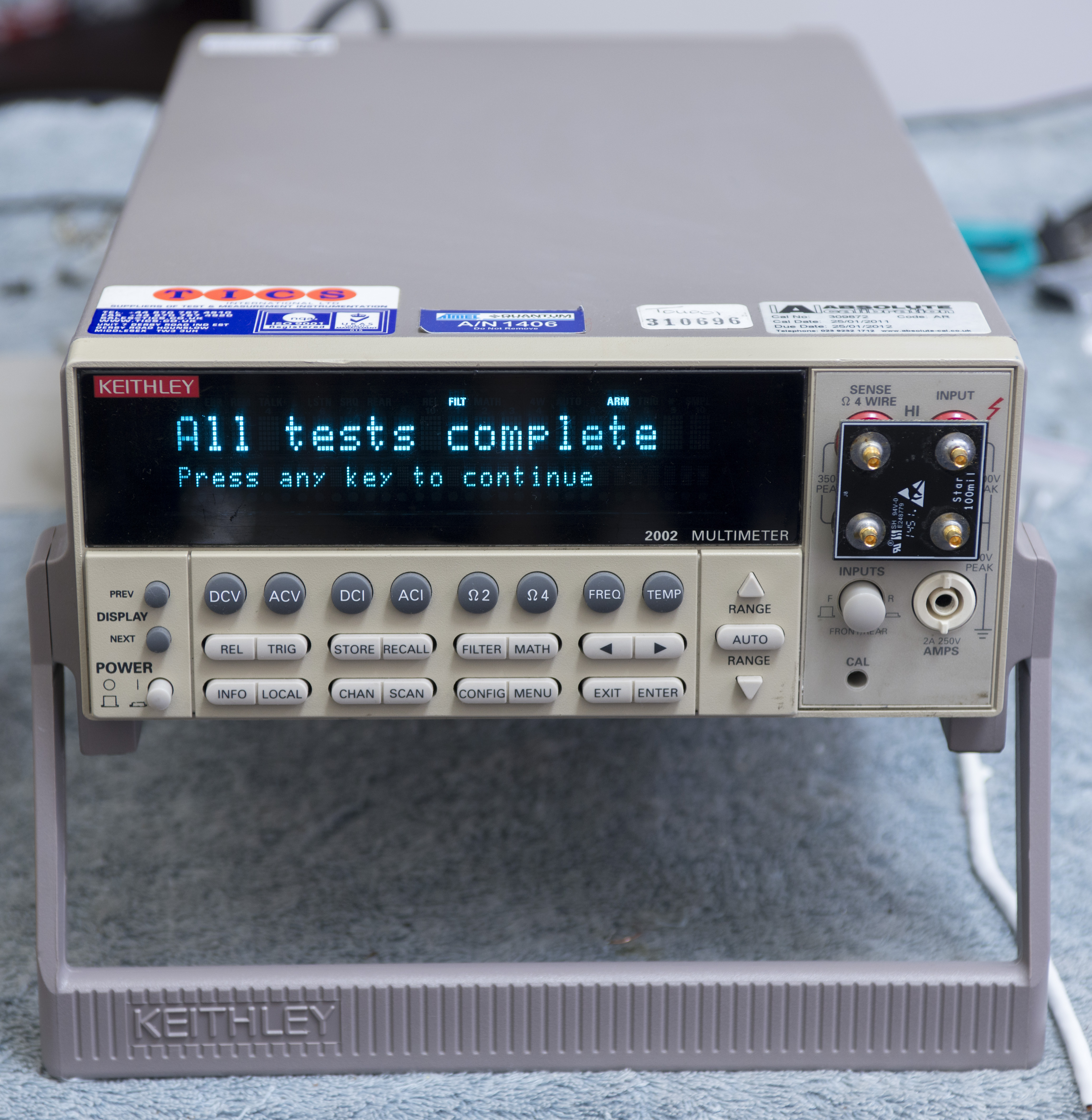
And here it goes, pass all tests with flying colors. There were few 406.6 (Sample/hold test) pop up first run, but that’s likely due to warmup time. I could not wait and ran self-tests right after power on. After 15 minute warm-up time, running self-test for 10 times in a row did not throw a single error. Repair complete!
Firmware
Firmware stored in standard JEDEC-compliant memory ROMs which can be UV EPROM or OTP PROMs. Some, but not all, compatible ROM ICs:
- ST 27C4001-15F1
- AMD 27C040 (UV EPROM)
- ATMEL AT27C040 (OTP EPROM)
- Toshiba TC544000P (mask ROM)
| Firmware version | Combined binary | ODD ROM | EVEN ROM |
|---|---|---|---|
| Model 2002 A04, Version 35.1, Jul 18 15:08:02 EDT 1994 | 2002-A04 | 2002-803-A04 | 2002-804-A04 |
| Model 2002 A05, Version 52.1, May 11 10:34:54 EDT 1995 | 2002-A05 | 2002-803-A05 | 2002-804-A05 |
| Model 2002 A06, Ver. 56.1, Feb 26 11:26:54 EST 1996 | 2002-A06 | 2002-803-A06 | 2002-804-A06 |
| Model 2002 A09, Ver. 69.1, Oct 23 09:26:16 EDT 2000 | 2002-A09 | 2002-803-A09 | 2002-804-A09 |
| Model 2002 A10, Ver. 74.1, Jun 10 14:30:55 EDT 2008 | 2002-A10 | 2002-803-A10 | 2002-804-A10 |
Based on binary comparison, firmware version A09 added support for Type N thermocouples and SPRTD which was absent in A06, at least based on text strings difference. Also there is new extra strings – HPR.HPRECISION, ISN, A4, B4, A7, B7, C7, RZERO, RZER. It seems that A06 have also only 9 settings profiles (SAV0 to SAV8), while A09 and later have 10 (SAV0 to SAV9).
HPR string is related to GPIB readings format, as explained in User’s manual, as well as other items.
SPRTD (RZERO, A4, B4, A7, B7, C7) settings are explained on page 233-234 as well.
One more person mentioned in A09’s credits: Justin Noble
I do not know what is difference between A09 and A10 version, as there are no public revision logs available. Combined binary images were merged using simple python tool:
# xDevs.com Firmware combine tool
# https://xdevs.com/review/kei2002/

import os

with open('2002_804_a06_even_0150fa76.bin','rb') as a:
    with open('2002_803_a06_odd_01c9ab74.bin','rb') as b:
        with open('K2002_A06_FULL.bin','wb') as x:
            for cnt in range(0, 1048576):
                x.write ("%s%s" % (a.read(1),b.read(1) ) )
There are also NVRAM dumps for reference:
| Memory option NVRAM | Dump |
|---|---|
| Unit 1 Option MEM2, DALLAS DS1248Y | Binary |
| This Unit 2 Option MEM2, DALLAS DS1248Y | Binary |
Calibration ROM dumps:
| Calibration ROM | Combined CALROM | Dump U633 | Dump U634 |
|---|---|---|---|
| Unit 1 original CAL ROM, Caldate 2007 | Binary | U633 Binary | U634 Binary |
| This Unit 2 original CAL ROM, Caldate 2010 | Binary | U633 Binary | U634 Binary |
Many other Keithley Instruments firmware dumps are available on xDevs.com documentation site
Article about different MEM options for Keithley 2001/2002 might be useful for those who want maximize memory without need of sending unit back to service center. Beware, as manufacturer warranty is void in such case.
Calibration
To be done..
Removing yellow front panel tint
There is separate guide on method of whitening old aged front panels tint, so I will not go too much in detail here, but would like to show overall before/after result with use of H2O2 and TAED bleach (scoop of Vanish) to whiten this Keithley 2002 front panel.
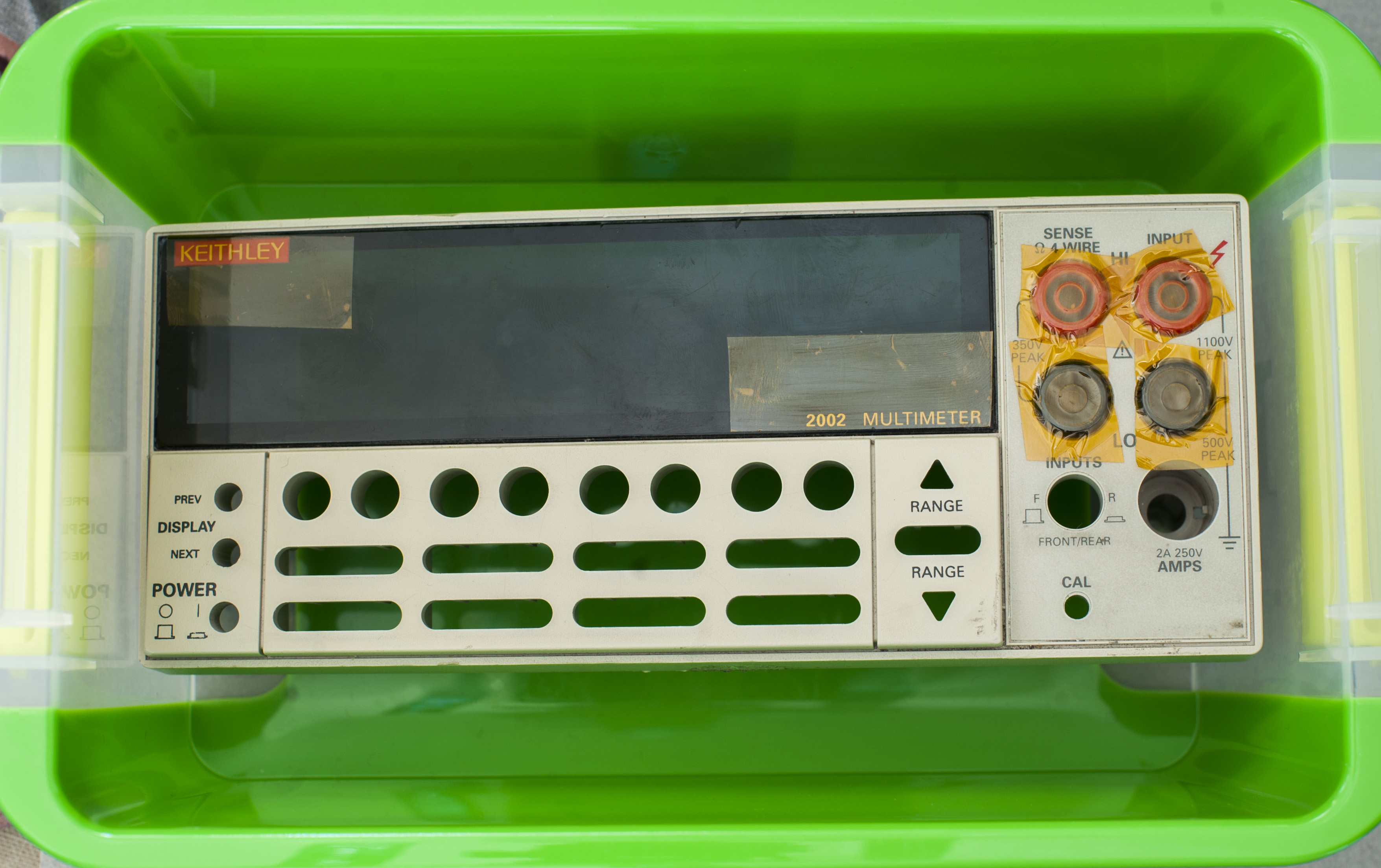
First few shots of panel from meter, as is:

Then the PCBA with screen glass, keypad, current input jack/fuse holder carefully removed and sat aside. We don’t want to damage fragile VFD.

Labels on translucent display panel were covered with capton tape to avoid damage from chemicals. I also taped jacks front to avoid liquid in them. Rear end of jacks left as is, as they are gold plated and should be fine.

Now whole panel was put into suitable size plastic box and filled with warm water with scoop of TAED in it and covered by hydrogen peroxide Vol.40 cream.
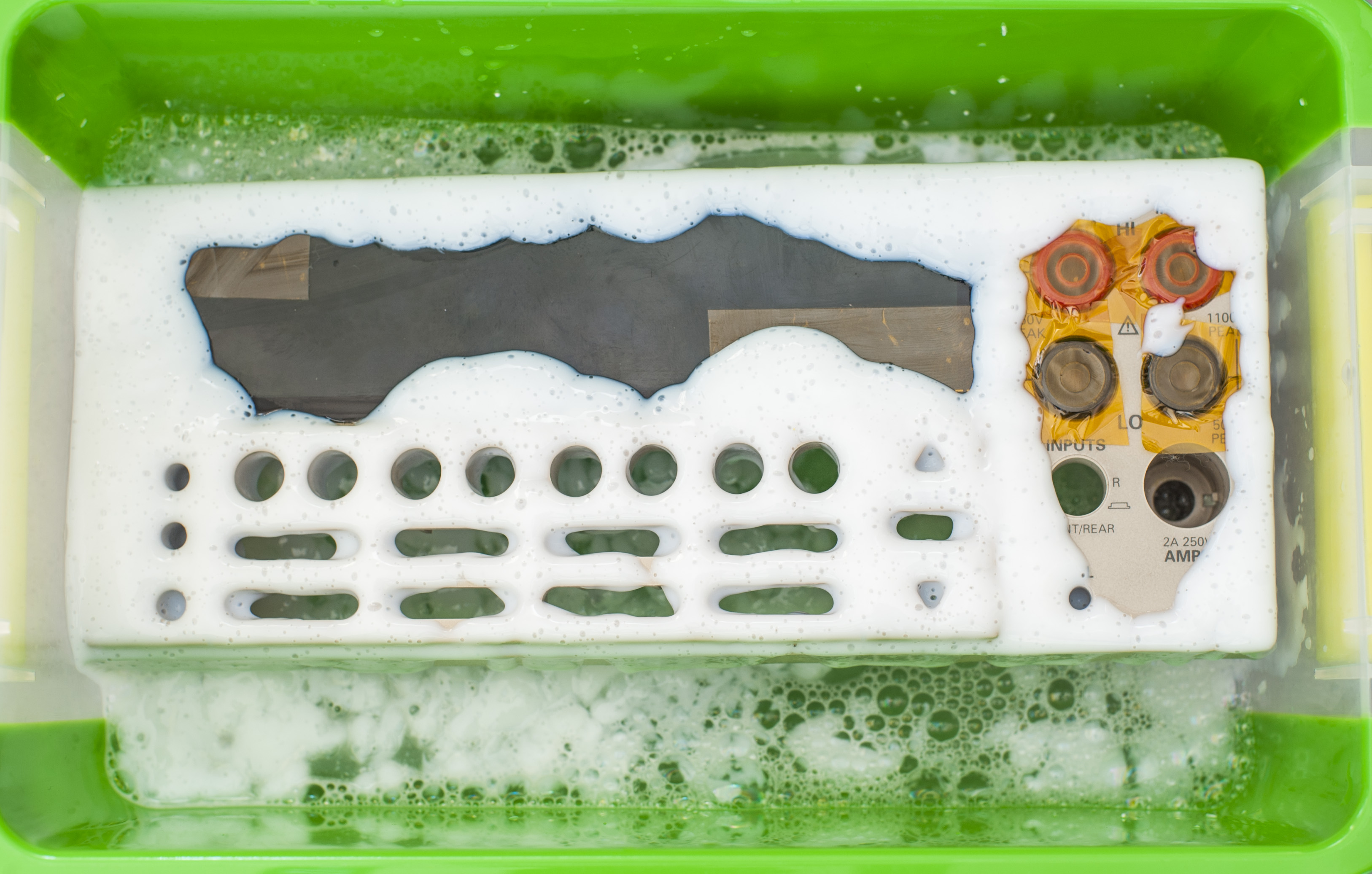
Then everything was put outside on direct sun for 3 hours to catch some UV and get process going. Here’s result:

Panel is noticeable whiter now. As drawback silkscreen paint got removed as well by TAED. I’ll avoid using TAED next time to confirm this theory.
Worth to note much cleaner look of golden pins of front panel jacks as well:

Fresh looking whitened Keithley family getting bigger:
Performance test
Interesting question was, does meter still have it’s accuracy and calibration valid after such extensive repair on mains side? There is no way to know that exactly, but basic test can be done to check meter’s accuracy. For that we will need stable known voltage reference and reference meter to compare with.
As source, I used one of best references, Linear LTZ1000A-based HP 3458A’s A9 board. This board was tested and measured by our fellow enthusiast Todd with his 3458A (calibrated June 2015) and calculated to provide +7.18460898 VDC output. As part of our experiment of transferring voltage to my homelab, module was shipped to me in cold state and I used it as known voltage standard. To avoid tempco influence, module was placed in thermally stable isolated metal can, with controlled temperature at +23.4°C via TEC module on it’s wall and help of Keithley 2510 TEC SMU. Temperature of the metal can proven to be stable within ±0.01°C by separate Honeywell HEL-705 platinum RTD measurement.
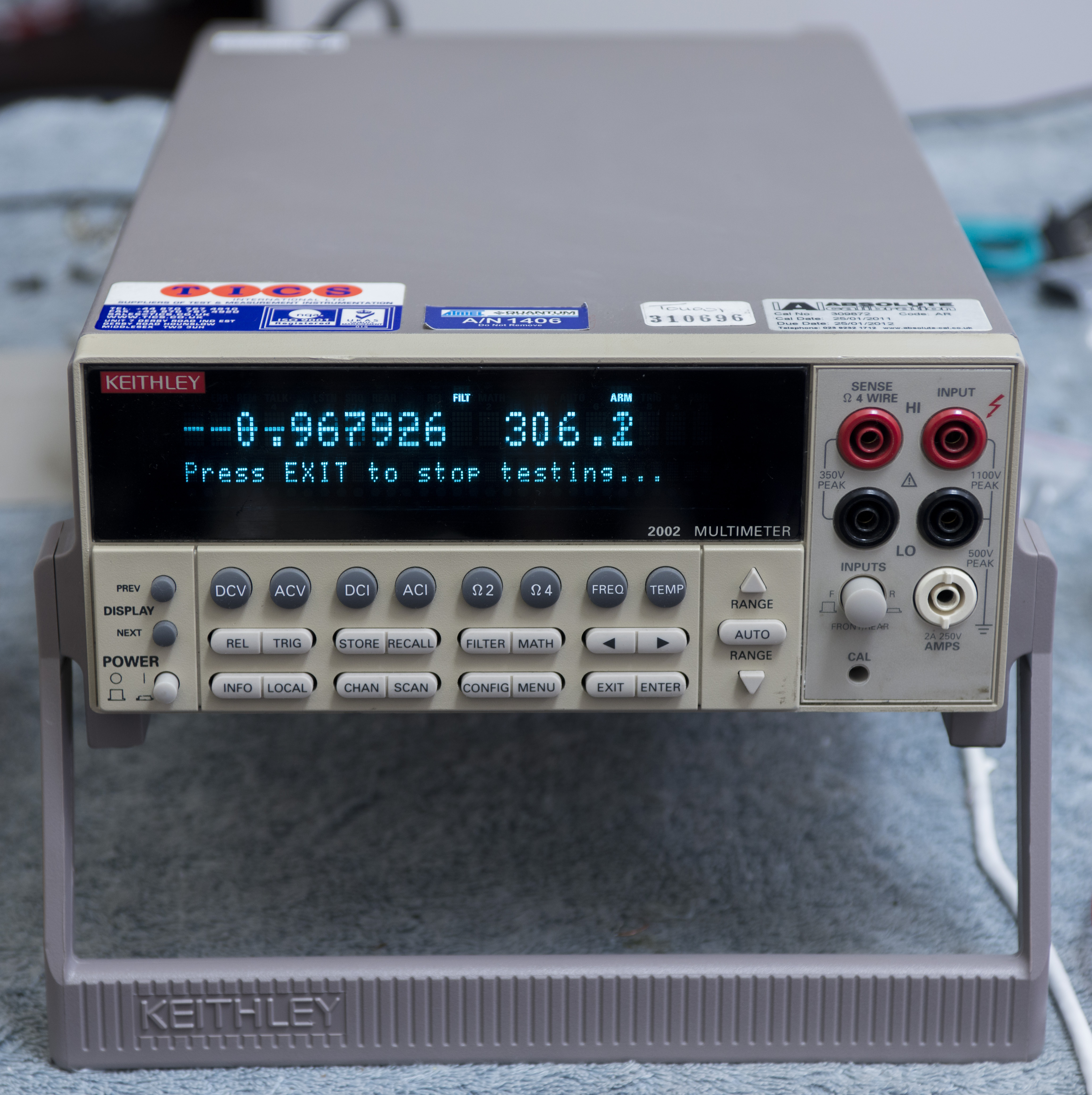
Reference meter for comparison was my HP 3458A which calibrated to this very same source, and proven to be stable. Freshly repaired Keithley 2002 was connected in parallel to 3458A’s binding posts. Keithley reading stabilized at +7.1846782 VDC, while reference was reading +7.1846058 VDC. That gives about +10.077 ppm of error. Not bad, considering last calibration of K2002 was before failure in 2009.
Conclusion
| Item | Cost | Shipping | Supplier |
|---|---|---|---|
| Dead Keithley 2002 | 950$ | 116$ | eBay |
| Replacement parts order | 197$ | 0 $ | Digikey USA |
Table 20: Project cost
Also some generic parts were ordered from DigiKey store, such as DC fan, capacitors, relays, ICs for analog board. Some electrolytic capacitors I already had from previous Keithley 2001 repairs. Here’s order list from Digikey with related part numbers.
| Index | Qty | Part Number | Description | Price USD |
|---|---|---|---|---|
| 1 | 10 | 296-1388-1-ND | IC DIFF COMP STROBE 8-SOIC | 3.87 |
| 2 | 50 | P20.0KAACT-ND | RES SMD 20K OHM 1% 1/2W 1210 | 5.30 |
| 3 | 1 | Z125-ND | RELAY GEN PURPOSE DPDT 2A 24V | 5.27 |
| 4 | 1 | Z3283-ND | RELAY GENERAL PURPOSE DPDT 2A 9V | 5.34 |
| 5 | 10 | H11AV1AM-ND | OPTOISO 4.17KV TRANS W/BASE 6DIP | 6.03 |
| 6 | 5 | 478-3894-1-ND | CAP TANT 1UF 50V 20% 2312 | 5.55 |
| 7 | 10 | 568-1390-1-ND | IC MULTIVIBRATR DUAL MONO 16SOIC | 3.85 |
| 8 | 5 | DG444DYZ-TCT-ND | IC SWITCH QUAD SPST 16SOIC | 9.40 |
| 9 | 5 | DG408DY-E3-ND | IC MUX CMOS ANG DUAL 8CH 16SOIC | 8.85 |
| 10 | 100 | 568-4510-1-ND | TRANS NPN 40V 0.2A SOT23 | 4.94 |
| 11 | 10 | ZM4732A-GS08CT-ND | DIODE ZENER 4.7V 1W DO213AB | 3.46 |
| 12 | 100 | MMBD914TPMSCT-ND | DIODE GEN PURP 75V 150MA SOT23 | 8.16 |
| 13 | 100 | BAV103-GS18CT-ND | DIODE GEN PURP 200V 250MA SOD80 | 9.58 |
| 14 | 10 | 445-15971-ND | CAP CER 100PF 1KV SL RADIAL | 2.01 |
| 15 | 10 | 1460PH-ND | CAP CER 10000PF 500V Y5P RADIAL | 3.18 |
| 16 | 20 | 568-6318-1-ND | DIODE ZENER 22V 250MW SOT23 | 2.84 |
| 17 | 20 | 568-6309-1-ND | DIODE ZENER 6.2V 250MW SOT23 | 3.90 |
| 18 | 100 | TBAV99LMCT-ND | IC DIODE SWITCHING 3SOT23 | 10.82 |
| 19 | 100 | 568-4511-1-ND | TRANS PNP 40V 0.2A SOT23 | 6.49 |
| 20 | 20 | 568-7091-1-ND | DIODE ZENER 39V 250MW SOT23 | 7.74 |
| 21 | 2 | 603-1486-ND | FAN AXIAL 40×15MM 12VDC WIRE | 26.68 |
| 22 | 10 | YAG2194CT-ND | RES SMD 10K OHM 0.1% 1/4W 1210 | 5.23 |
| 23 | 1 | A102483-ND | RES 470 OHM 7W 5% RADIAL | 0.66 |
| 24 | 10 | 399-3734-1-ND | CAP TANT 10UF 25V 10% 2413 | 6.59 |
| 25 | 5 | 4603PHBK-ND | CAP ALUM 1000UF 20% 50V RADIAL | 5.40 |
| 26 | 20 | NDS0610CT-ND | MOSFET P-CH 60V 120MA SOT-23 | 6.42 |
| 27 | 10 | 1MWCT-ND | RES 1M OHM 1W 5% AXIAL | 1.36 |
| 28 | 10 | YAG2261CT-ND | RES SMD 33 OHM 0.5% 1/4W 1210 | 3.91 |
| 29 | 5 | P243KBCCT-ND | RES SMD 243K OHM 0.1% 1/4W 1206 | 4.70 |
| 30 | 10 | 764-1215-1-ND | RES SMD 499K OHM 0.1% 0.4W 1206 | 9.60 |
| 31 | 5 | PAT2.49KCCT-ND | RES SMD 2.49K OHM 0.1% 0.4W 1206 | 5.20 |
| 32 | 100 | 311-243KFRCT-ND | RES SMD 243K OHM 1% 1/4W 1206 | 1.30 |
| 33 | 100 | YAG2296CT-ND | RES SMD 1K OHM 1% 1/2W 1210 | 3.00 |
| Total | 196.63 |
Table 21: First Digikey order for parts
Total repair cost in parts as for today: $1262.64 USD
| Date | Activity | Time spent |
|---|---|---|
| 3/13/2016 | Received unit, initial teardown | 1 hour |
| 3/14/2016 | Cleaning analog PCB, test digital and FP PCBA | 2 hours |
| 3/16/2016 | Order components and parts for repair from DigiKey | 2 hours |
| 3/21/2016 | Parts from DigiKey arrived, installed components into DMM | 7 hours |
| Taking photos, writing up article sections and posts | 4 hours |
Table 22: Time worklog summary
Total man-hours spent on this project around 16 hours, give or take few. Was it worth doing? That’s up to you, so please leave your comments, so I can do more stuff like this.
Equipment used during restoration project:
- Soldering gear, ERSA I-CON station
- MiniPro TL866CS programmer to read/write ROMs/RAMs
- Keithley 2002 DMM (calibration 2007)
- HP 3458A (calibrated 3/20/2016 to artifact 10V/10KΩ)
- HP 3245A
- ±30 ppm/K EDC MV106 DC voltage standard (calibrated 02/2014 from K2001)
- ESI DB52 resistance decade to test OHM operation
- Set of Vishay foil resistors for resistance artifact calibration
- Nikon D800 with 28-70/2.8D, Sigma 150/2.8 Macro, 50/1.4D lenses, tripod
- 0.25L of IPA and alcohol to clean chassis and parts
- Google – used lots of it!
Credits and thanks to Todd, Alan and all our readers to make this all possible. If you find typo or have any questions feel free to leave comment or contact us.
Projects like this are born from passion and a desire to share how things work. Education is the foundation of a healthy society - especially important in today's volatile world. xDevs began as a personal project notepad in Kherson, Ukraine back in 2008 and has grown with support of passionate readers just like you. There are no (and never will be) any ads, sponsors or shareholders behind xDevs.com, just a commitment to inspire and help learning. If you are in a position to help others like us, please consider supporting xDevs.com’s home-country Ukraine in its defense of freedom to speak, freedom to live in peace and freedom to choose their way. You can use official site to support Ukraine – United24 or Help99. Every cent counts.
Modified: June 6, 2026, 10:19 p.m.