Contents
Introduction
Followed by our Kei2001 endevaours, many may quickly found another kind of instruments from this vendor. SourceMeters, which are mix of precision current source, voltage source and DMM. SourceMeter series is not just a 6½ digit DMM, but actually combines three instruments in one. Keithley have variety of SMUs for different use requirements.
First is fast and precise 6½ digit DMM, with ability to measure voltages, currents and resistance.
Second – precision power source, with adjustable compliance levels (limits) for both voltage and current.
Third – given it’s four-quadrant power unit, it can not only source but also sink current, acting as active load.
All these functions are synced together and operate using same controls, which making use of it as easy as just normal power supply, but with much higher functional and precision/accuracy level. These units are widely used in semiconductor and production testing and covered from “simple” 20W units like this Model 2400, to advanced systems with multiple channels and wide ranges from picoamps to tens of amps. And even base 2400 cost significant money, I got this SMU with broken VFD, and still had to pay over 1000$.
After salvaging display from trashed Model 2001 and replacing it – unit worked like a charm. Let’s take a look in details:
Every photo below is clickable to open high-resolution, so enjoy exclusive photo coverage of Keithley Model 2400. I was trying to find any internal photos on web before, but failed.
Exterior
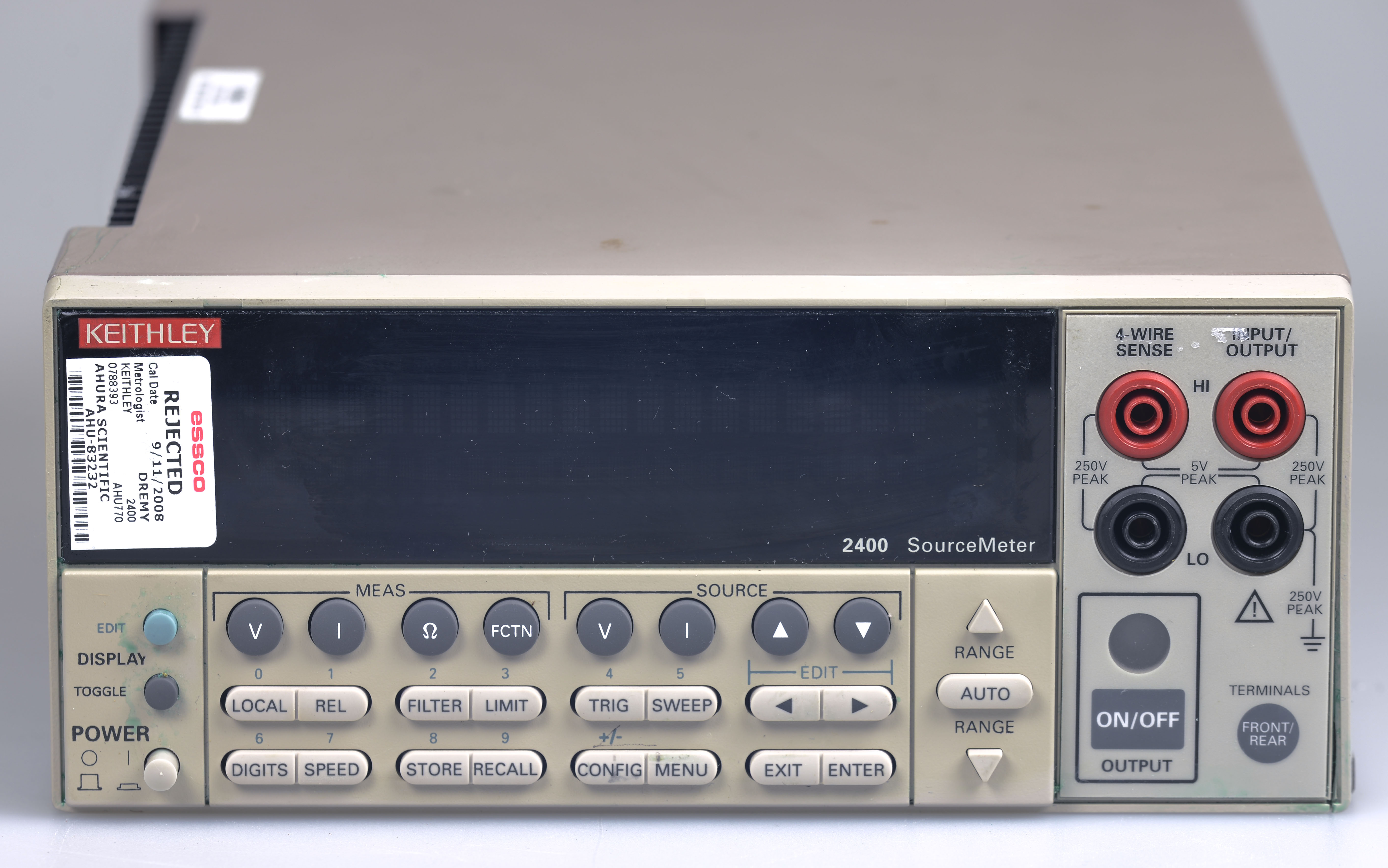
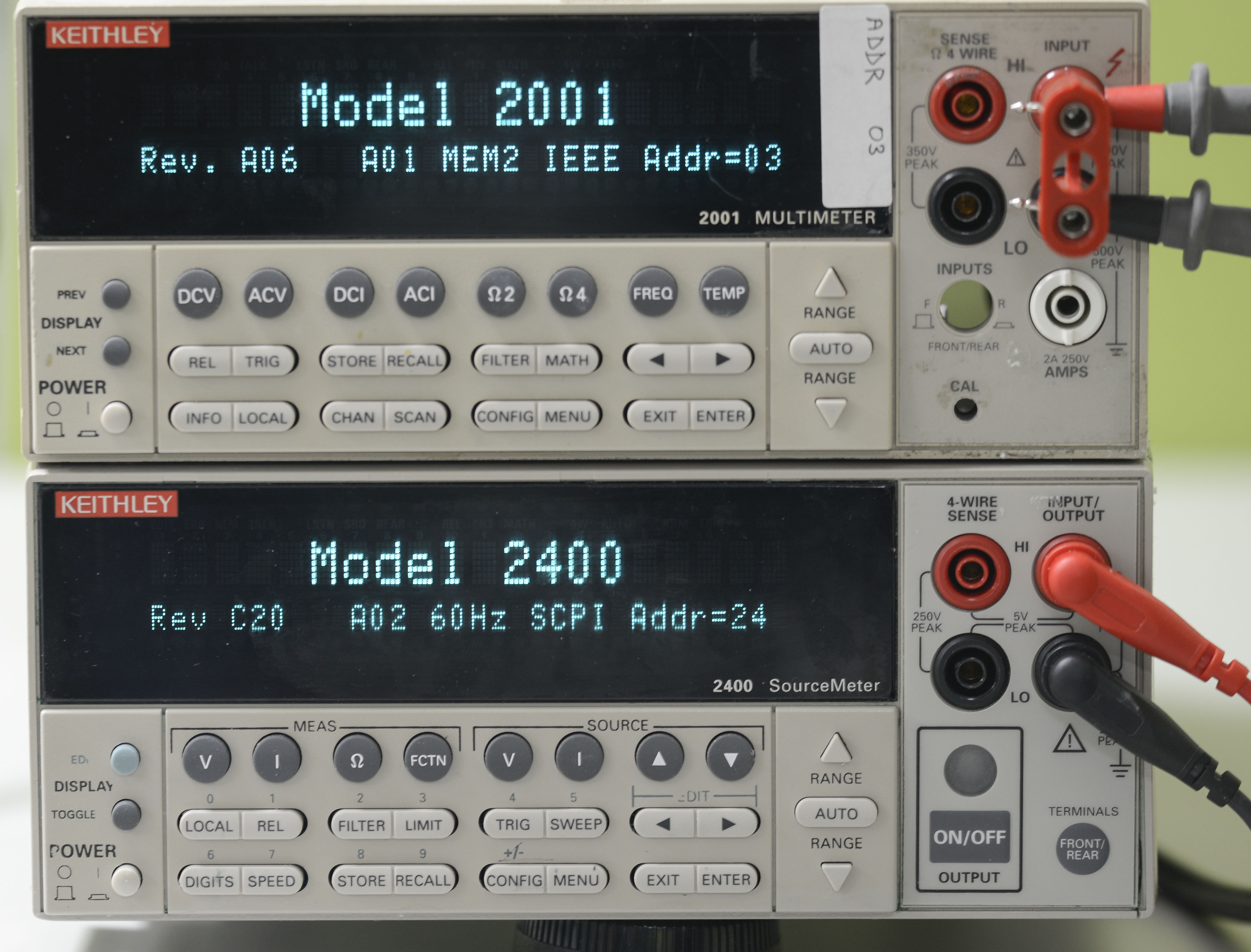
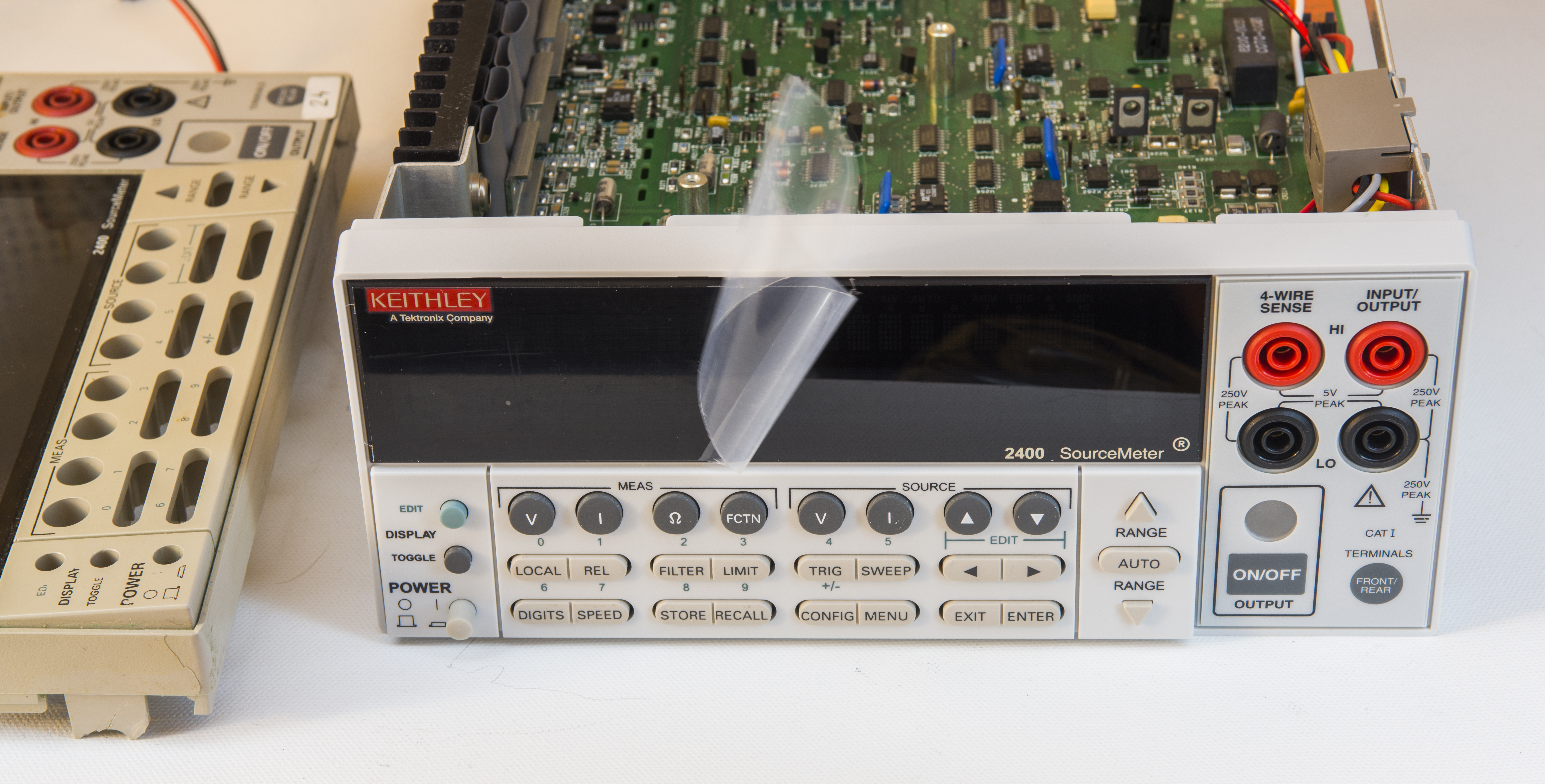
It’s done in common half-width 19” unit format, just like popular 2000-series DMMs, featuring same bright contrast dot-matrix VFD as Model 2001,2002,7001,7002 has.
Front panel is similar to DMMs, membrane keypad and front inputs. Due to ability of source current/voltage it have button to enable output.
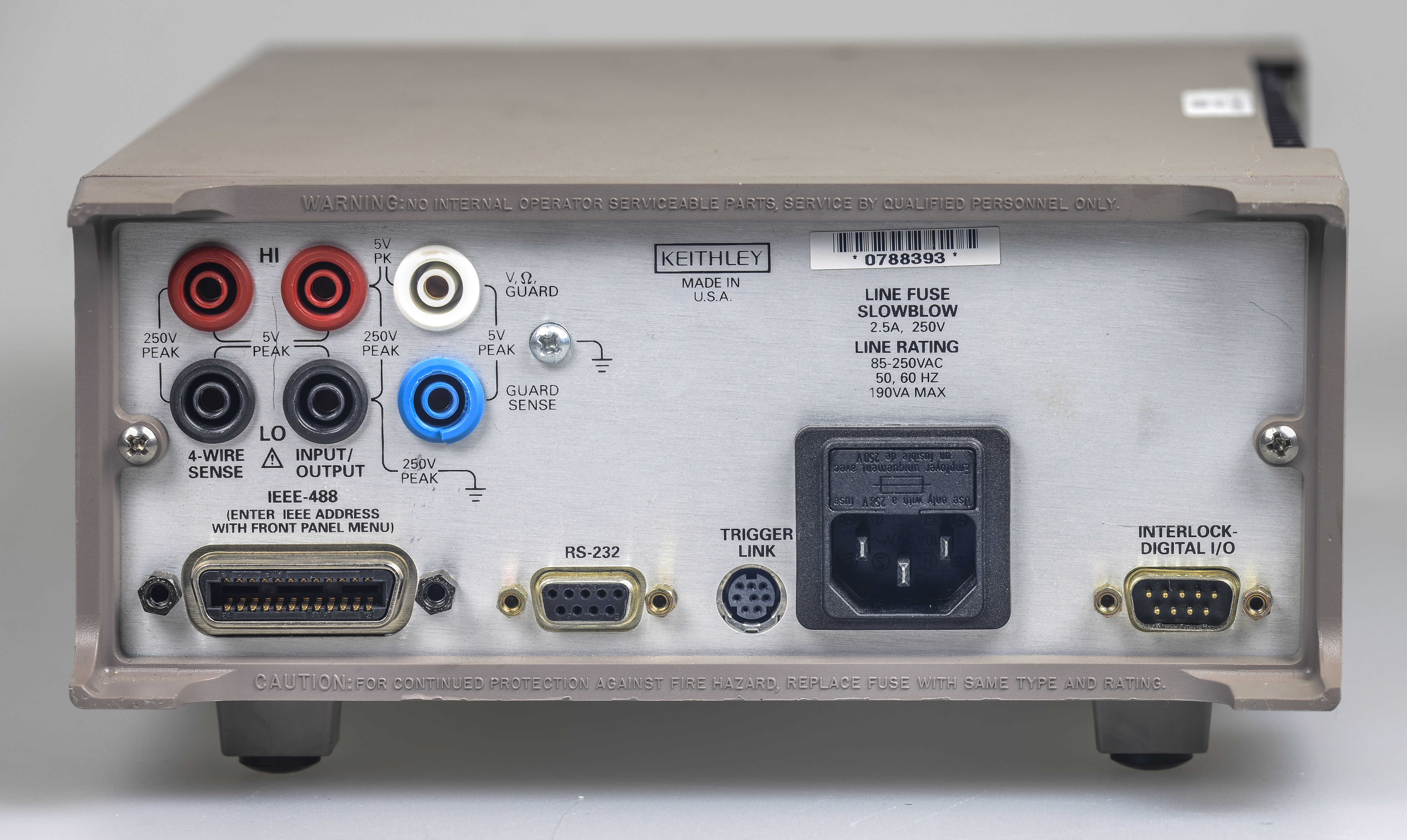
Rear side have inputs as well, adding guard output and guard sense input. This comes handy to perform unique 6-wire measurements, which is useful when one trying to source tiny voltages/currents into test device or measuring gigaohms level resistance. Rest items on this side quite usual, GPIB port, RS232 port, mains IEC power input (have versatile 85-250VAC 50/60Hz input) and digital I/O connector. Also have Keithley’s Trigger link to team with other SourceMeter or measurement instruments for syncronised operation.
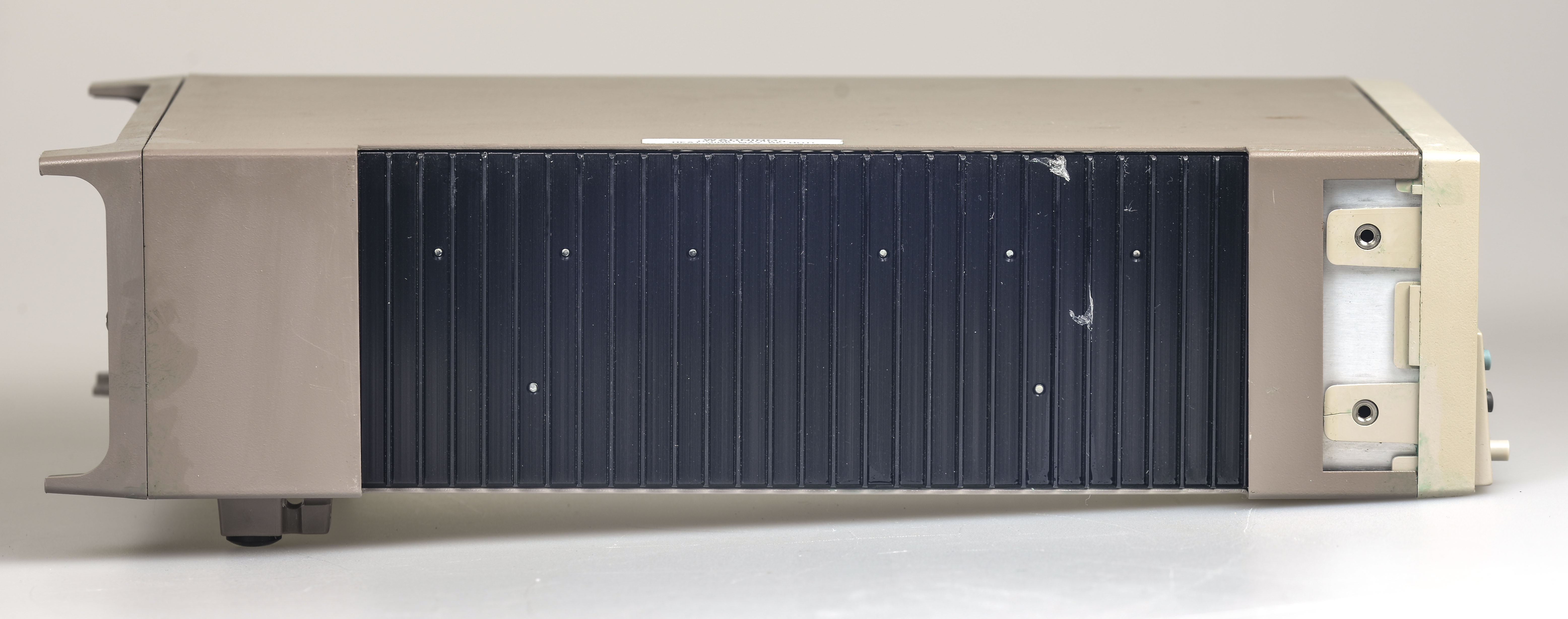
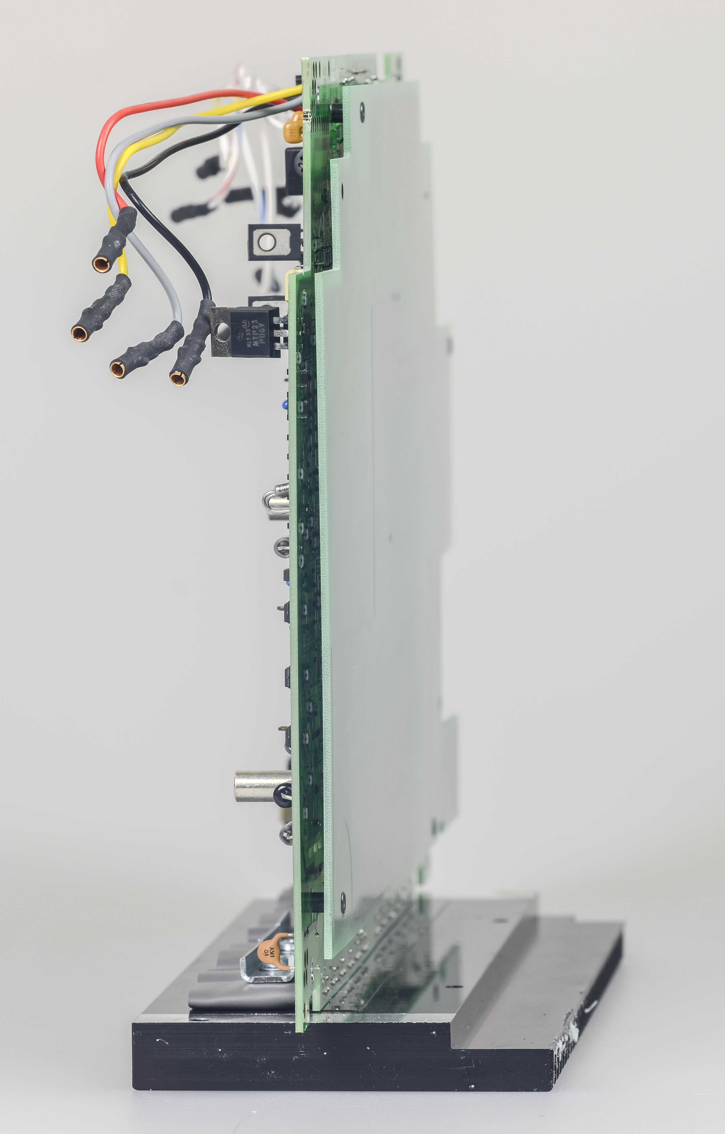
Model 2400 is fanless, so it’s producing zero noise, which is nice for home use. Left side have massive heatsink to dissipate heat from output stage.


My unit was abused by previous owner with some sticky ugly blue liquid which is hard to clean and front panel had few cracks here and there.
Will replace front panel plastic later probably, if it’s not too expensive.
Don’t turn it on, tear it apart!
Internals
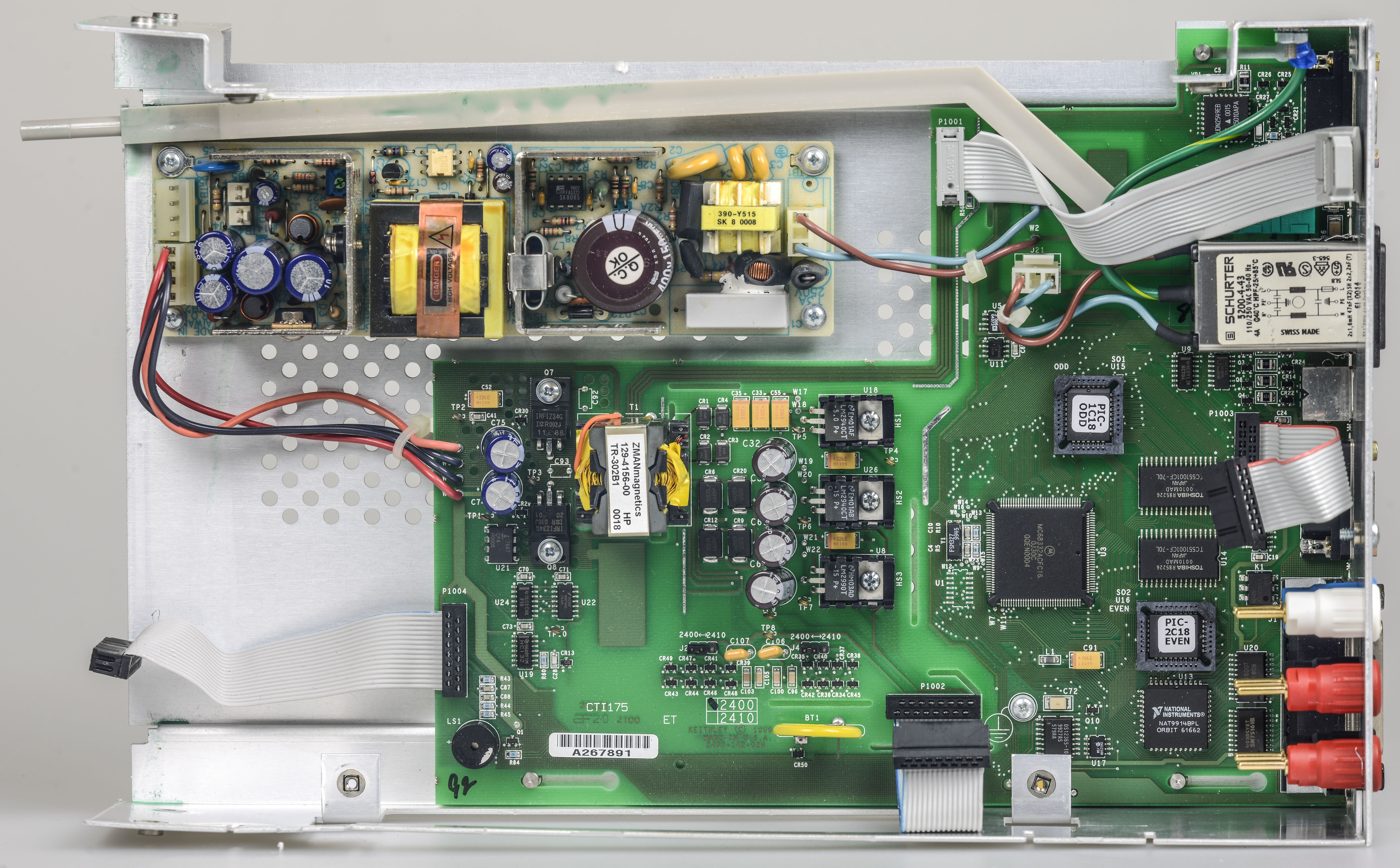
If you have 2000/2001 DMM and disassembled it, 2400 is no different in disassembling. Two screws from back, two screws on bottom, and we are in.

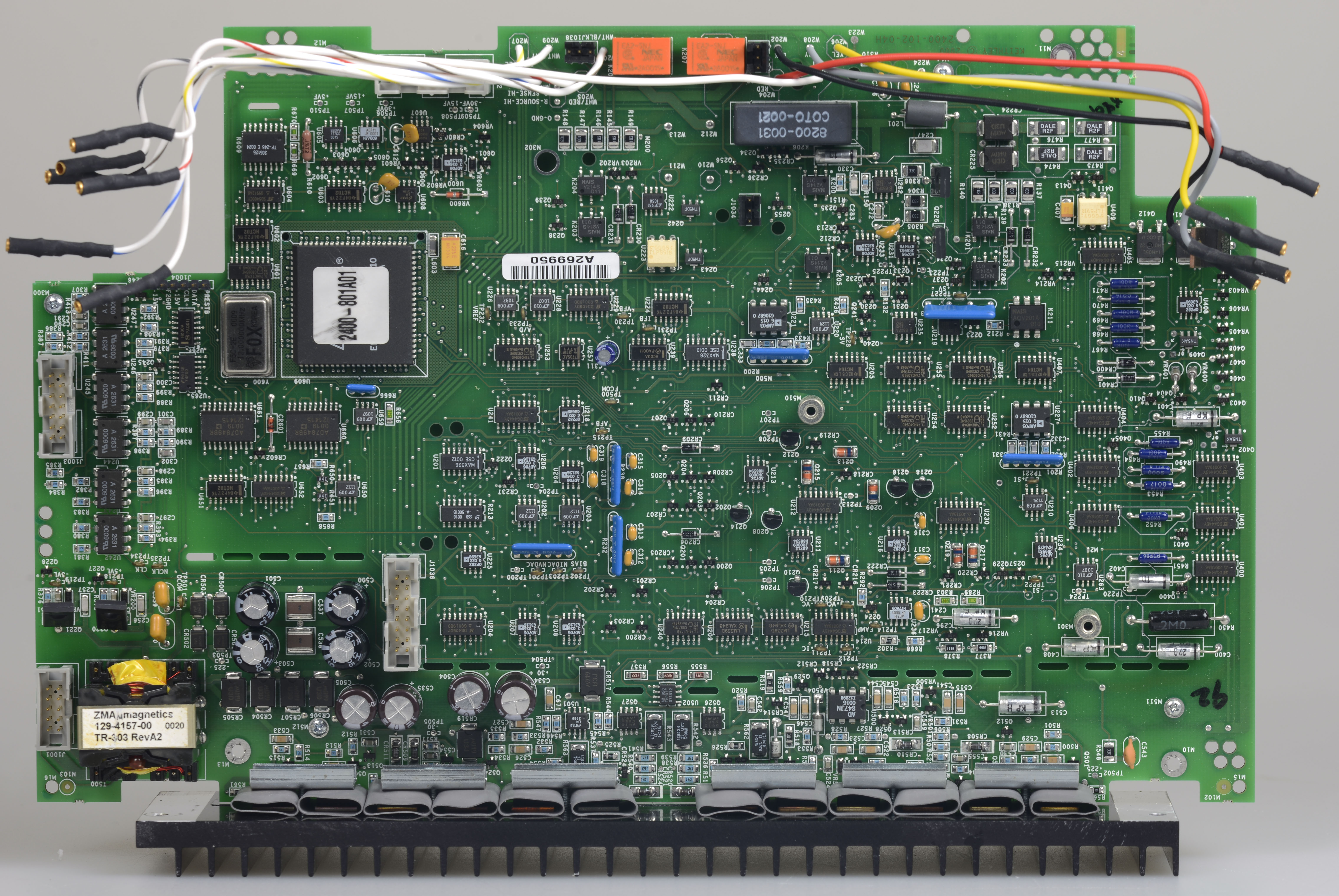
Top board is analog voodoo section, with all sourcing/measuring magic and dozens of expensive Linear Tech, Analog devices opamps, comparators.
ADC is once again using integrating discrete solution, with digital section implemented in ALTERA MAX7160 CPLD.
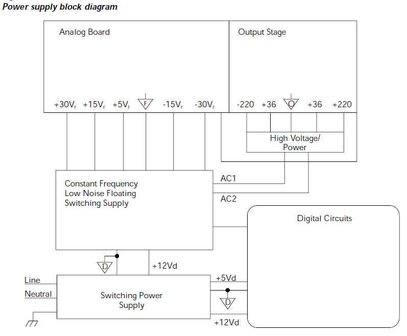
Under analog board we can find switching power supply and digital brains board. Thanks to SMPS there is no bloody mains switching curcuitry like in Model 2001/2002. :)

Analog board shielded from digital and SMPS section by another PCB without any components, but only with copper polygons.
That board covers most of analog bottom side and fixed on standoffs:
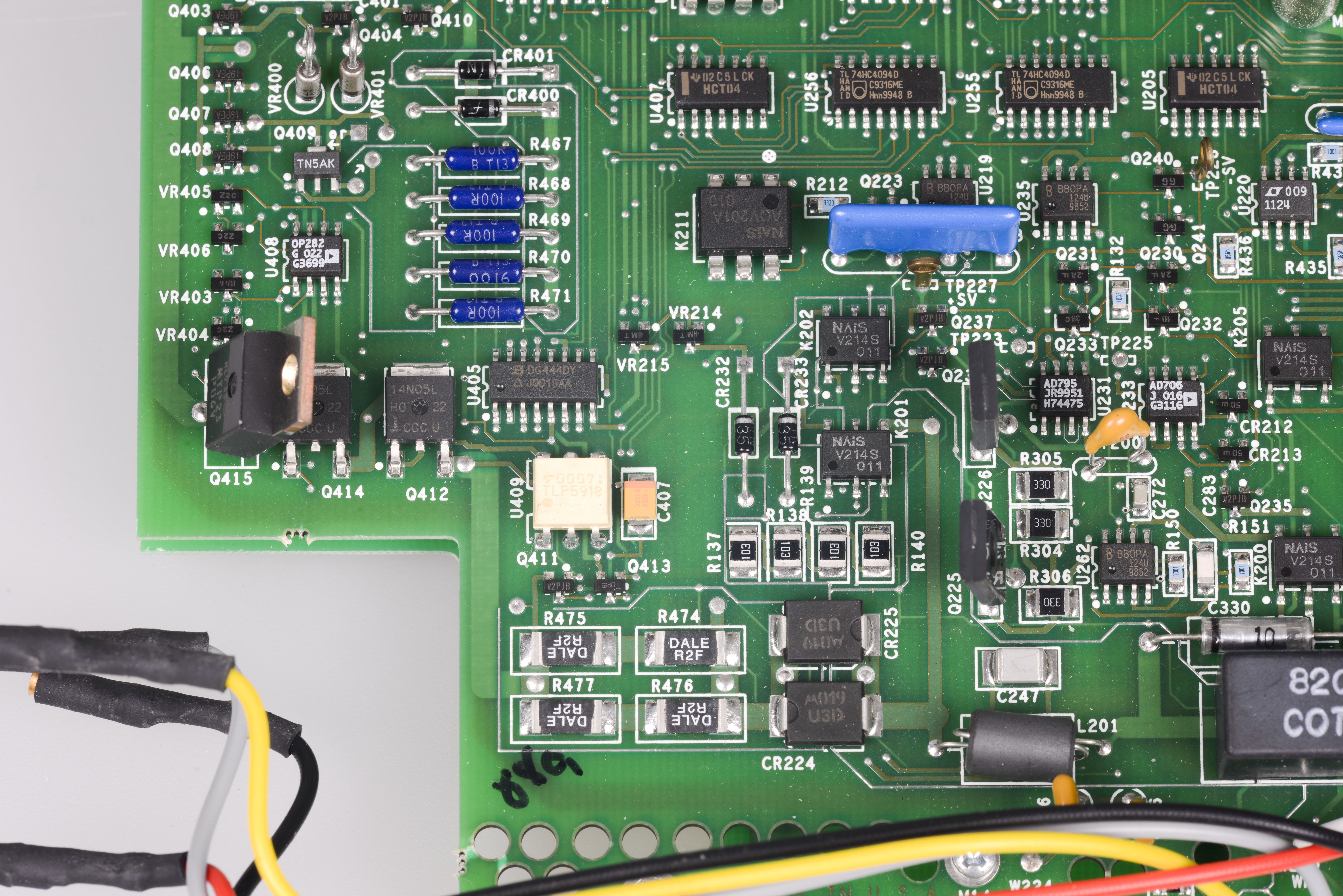
Analog voodoo
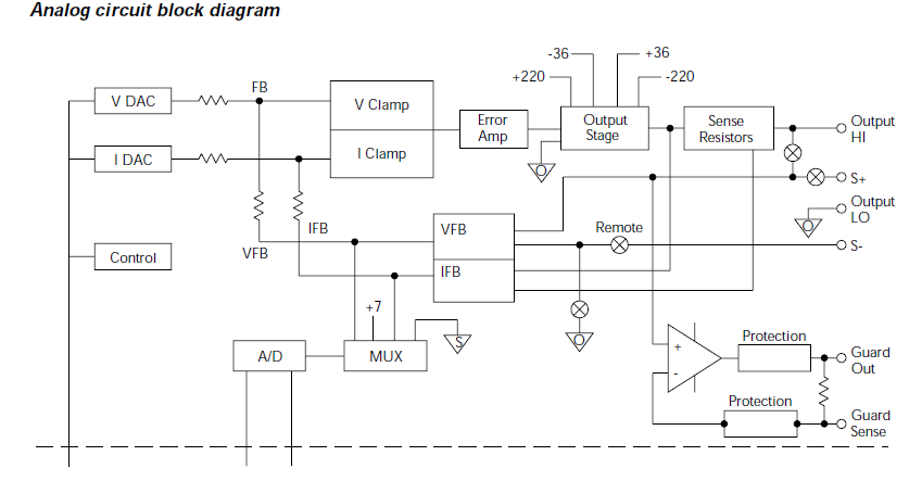
Of course, there is no schematics available, just like with every recent Keithley instrument. Pity, it could be pretty educating to learn thru different solutions used on this level of instruments.
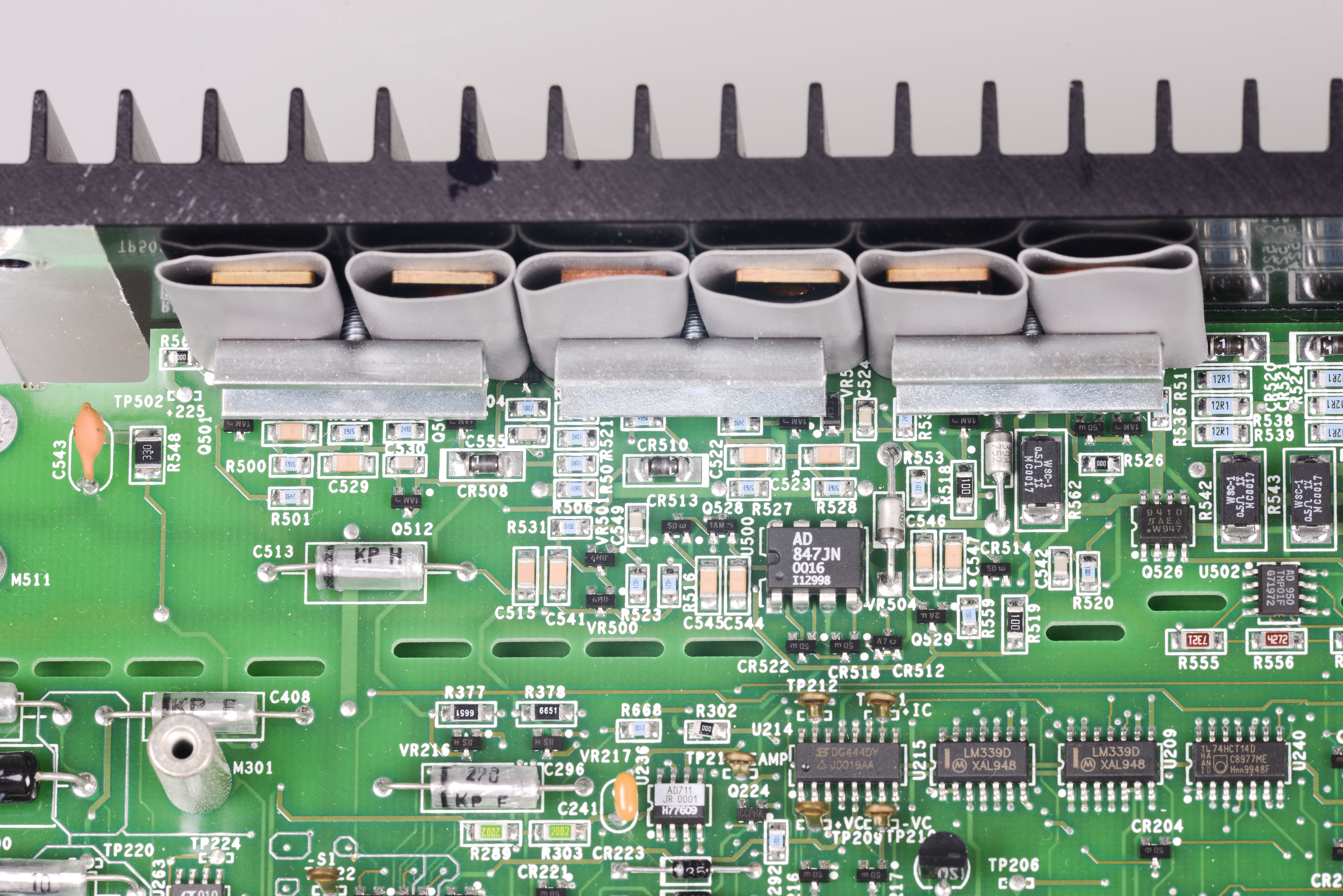
Output stage
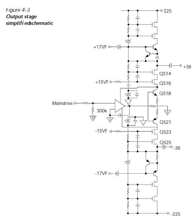
All bottom side of PCB on photo is output stage, which can source power with high precision. All power devices installed on aluminum heatsink
for cooling. During operation that heatsink getting warm, but not hot (+50-55C max), which is just normal for 20W capable unit.
Left corner have optical isolators for communication between digital PCB from below and analog world.
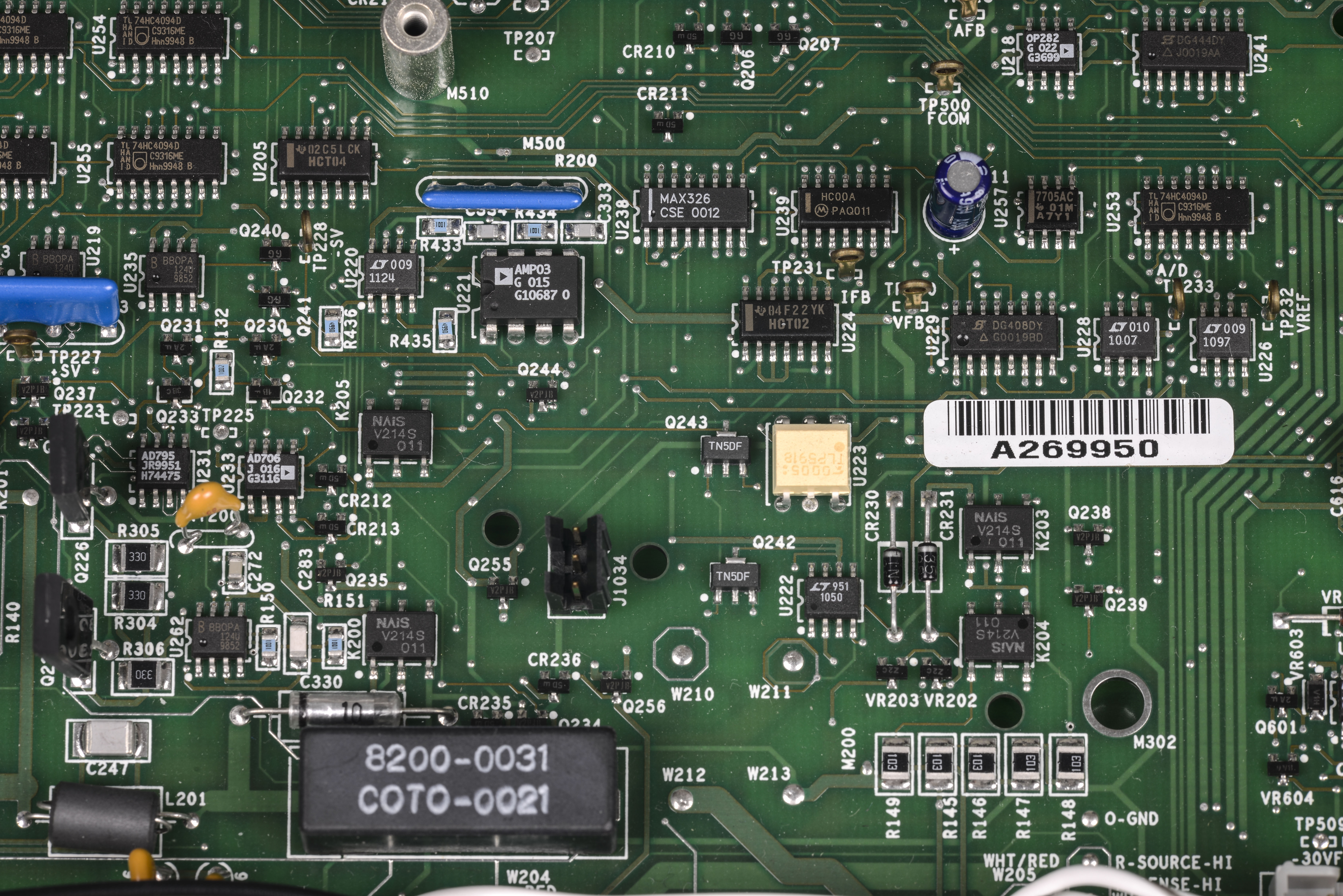
I could not spot voltage reference on this board, it’s not using LM399 like Keithley DMMs, but probably use zener or integral reference. There is TP232 test point just near serial number sticker marked as VREF tho. Its connected from LT1097 opamp output (U226)
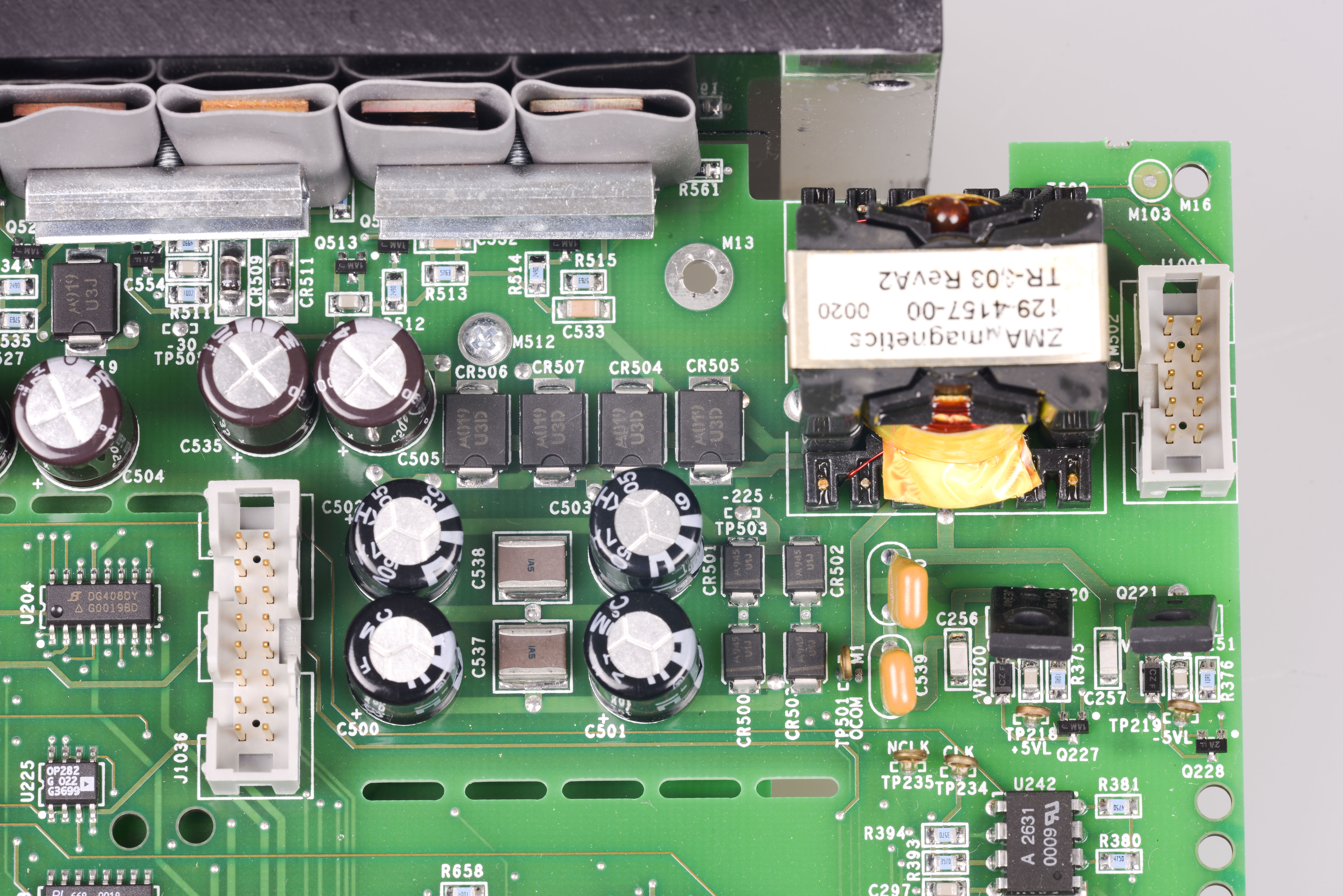
Output stage power source, ZMA Magnetics transformer to provide -225 and 225 voltage source, driven by two transistors on right left.
All output stage section have separation and HV PCB cutouts from rest of analog stuff, nice attention to details.

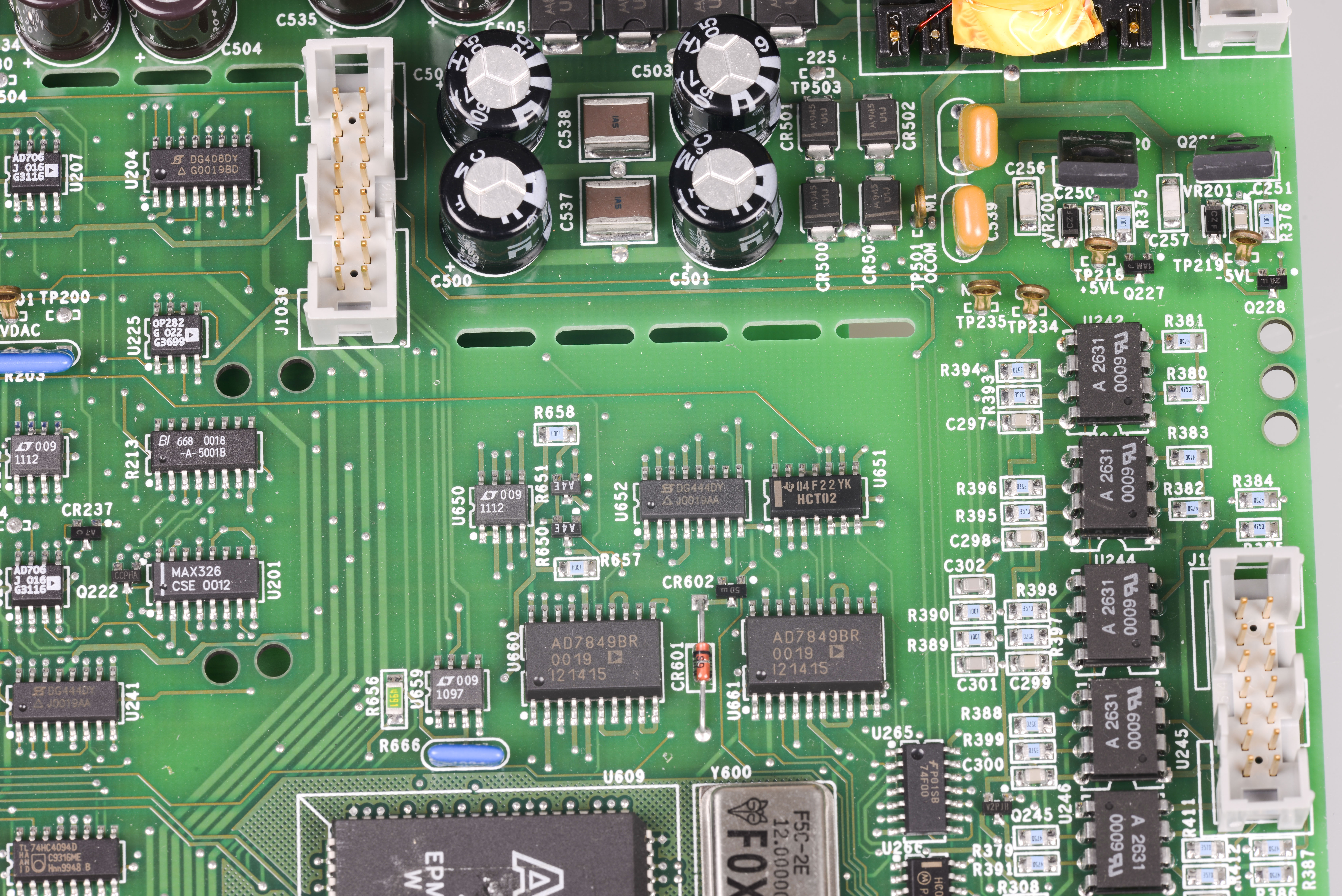
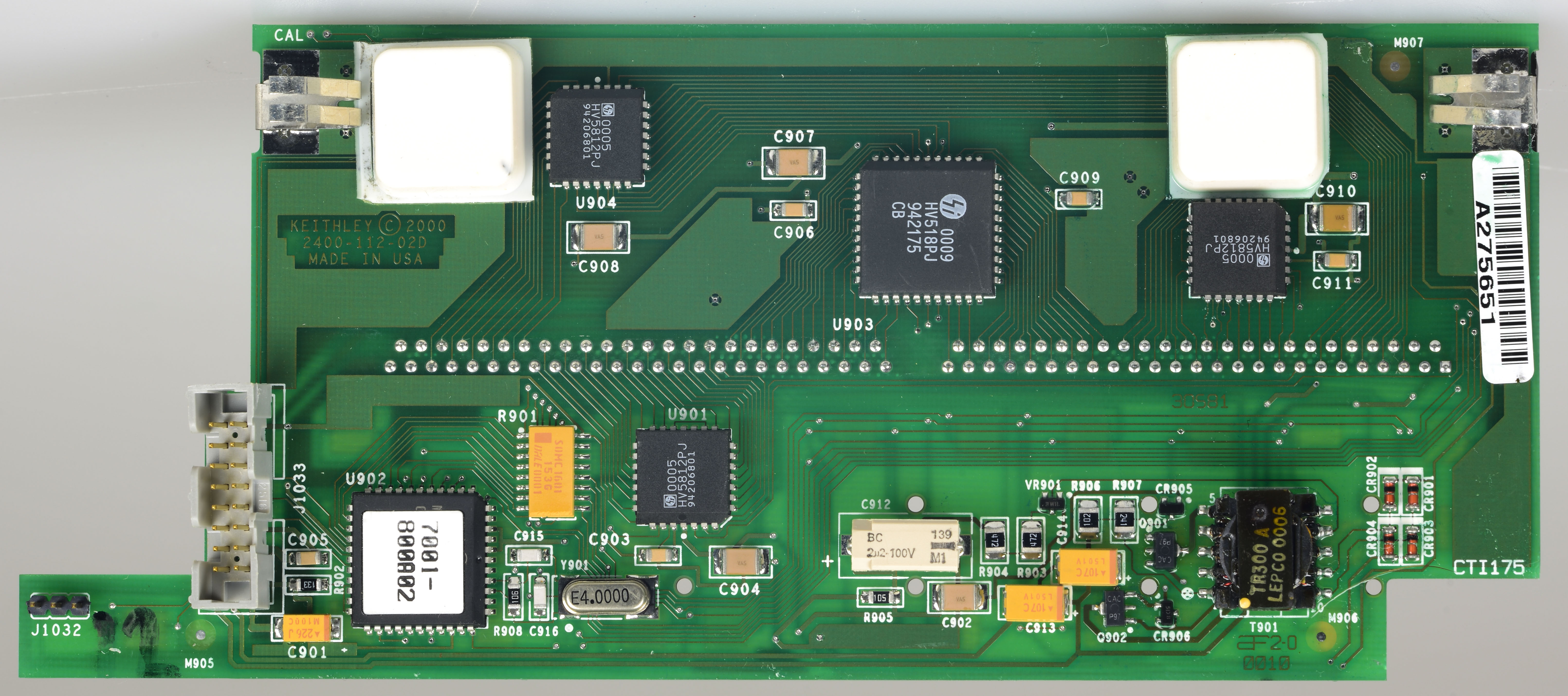
Integrating ADC

Big beefy EPM7160 in PLCC84 package, just like Model 2002. It’s configuration have label 2400-801A01. Clock is delivered from FOX 12.000000MHz CMOS generator nearby. There are two 16-bit DACs, Analog Devices AD7849BR? near it, and bunch of opamps. R609 is TF245 resistor network, which was spotted before in Model 2000 DMM :)
I’ll quote service manual here
The SourceMeter unit uses a multi-slope charge balance A/D converter with a single-slope rundown. The converter is controlled by gate array U610. Commands are issued by the MPU on the digital board through communications opto-isolators to U610, and U610 sends A/D reading data back through opto-isolators to the digital board for calibration and processing.
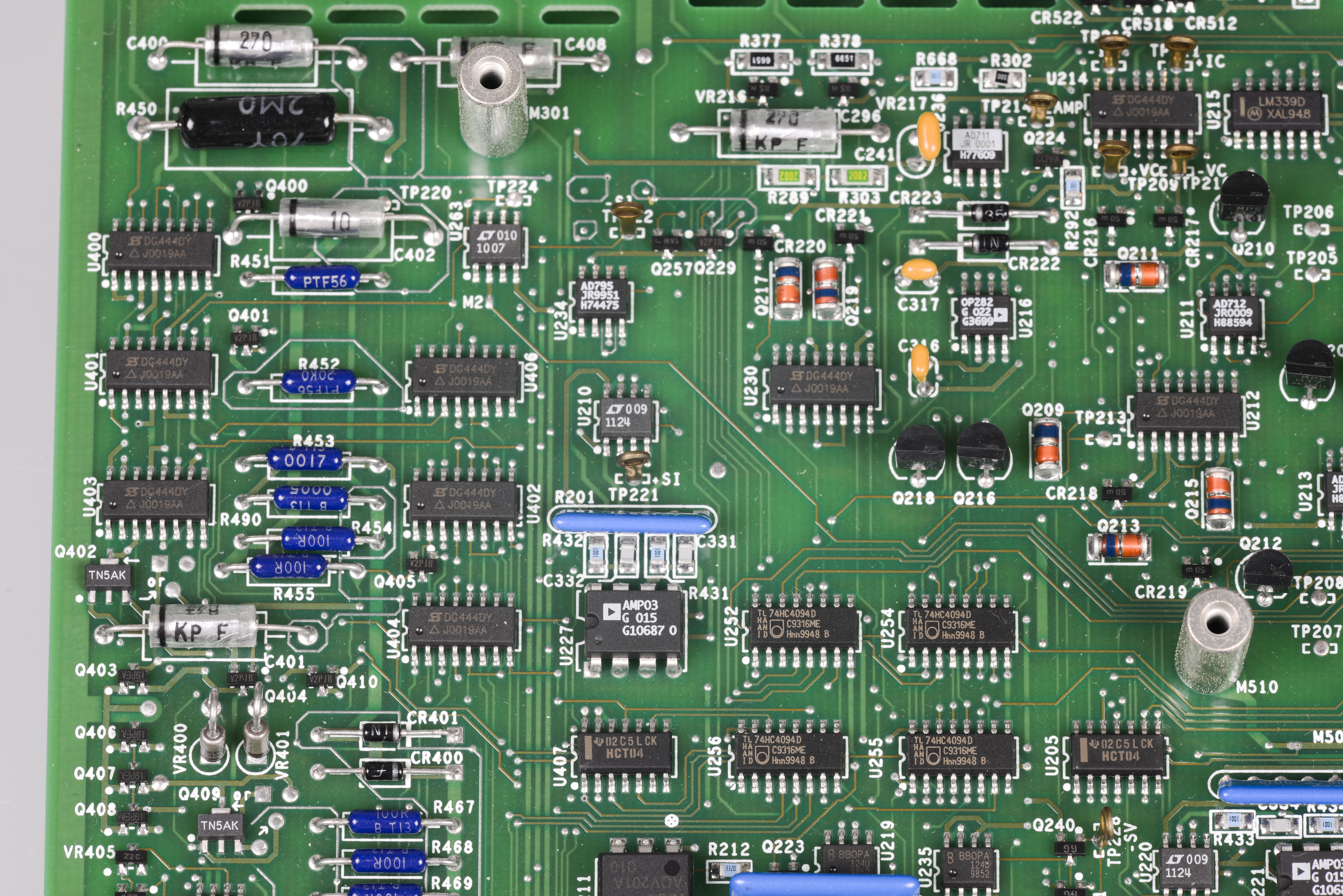
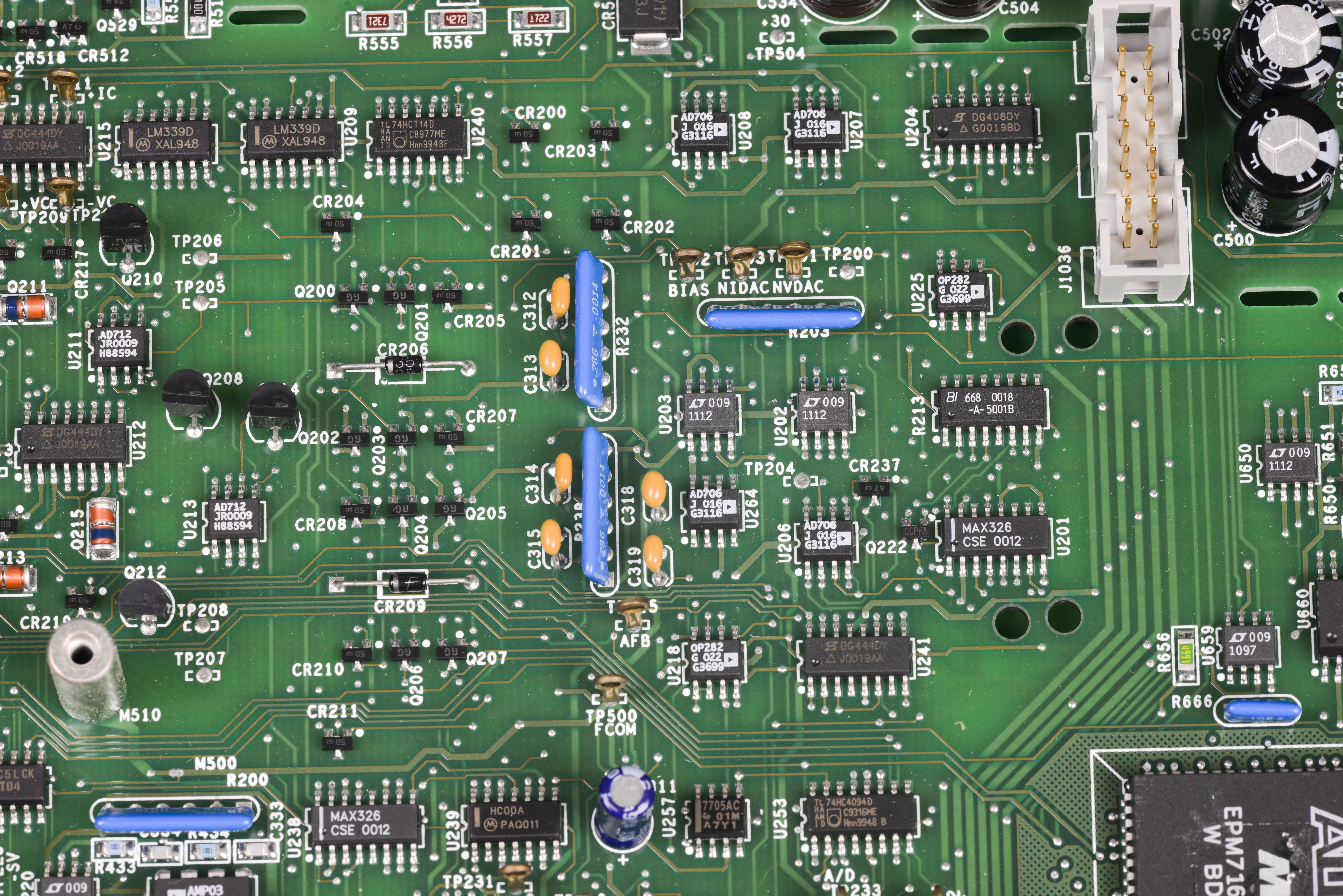
Rest of analog board photos:
Digital side board:
Service manual quote again:
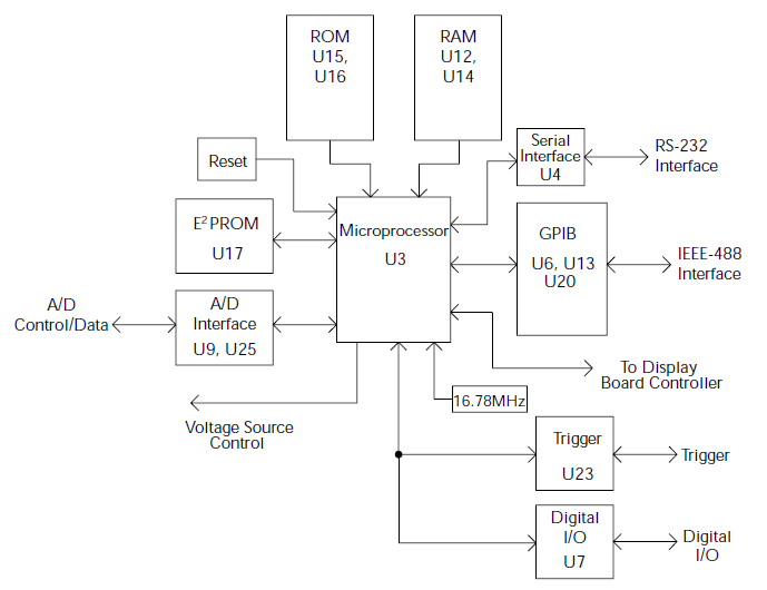
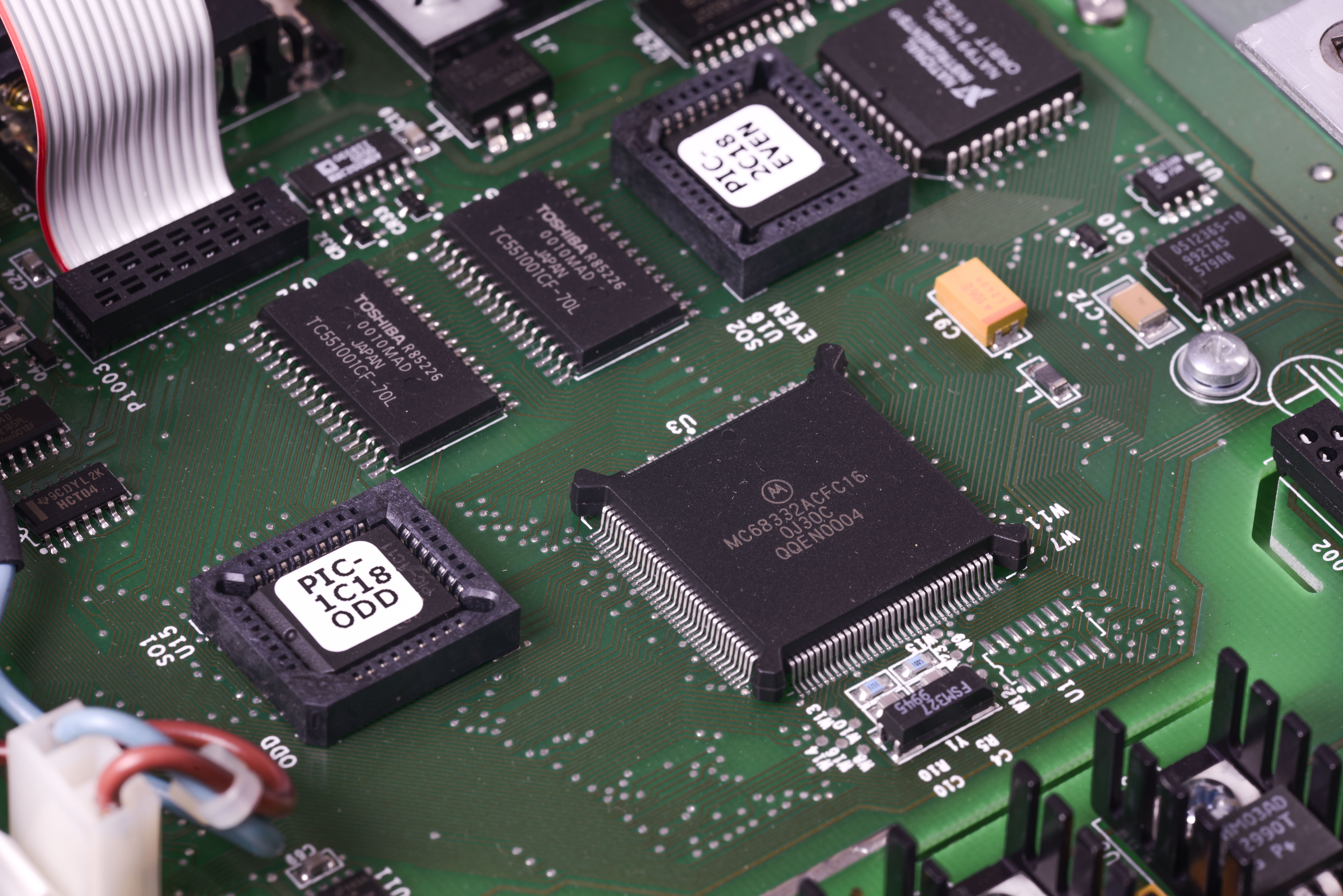
The core digital circuitry uses a Motorola 68332 microcontroller running at 16.78MHz.
The memory configuration includes:

2 x two 256Kx8-bit EEPROMS
2 x 128Kx8-bit RAMs

They are used in parallel to utilize the 16-bit data bus of the MPU. The RAM is battery backed-up, providing continued storage of data buffer information during power-down cycles. All calibration constants and system setups are stored in a separate serial EEPROM.
So we are safe here and 2400 will not brick itself when battery go bad after dozen of years.
No much component magic here, it’s similar to other Keithley products of that era.

Some LDO power for digital domain.
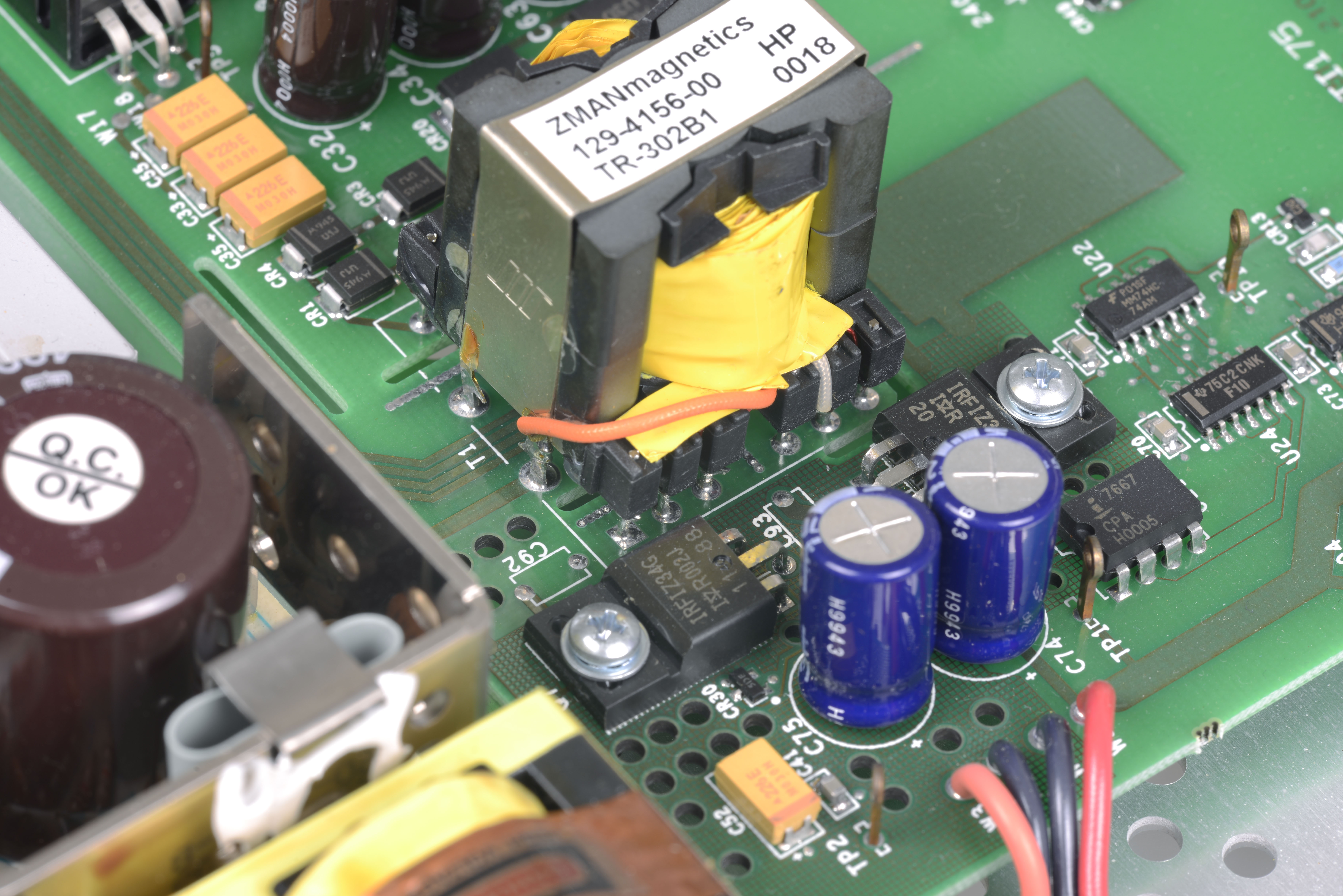
Another SMPS with ZMA Magnetics transformer.

Battery for RAM and two configuration jumpers. Based on silkscreen labeling, same digital board is used for both Model 2400 and Model 2410 SMUs (2410 can source up to 1100V)
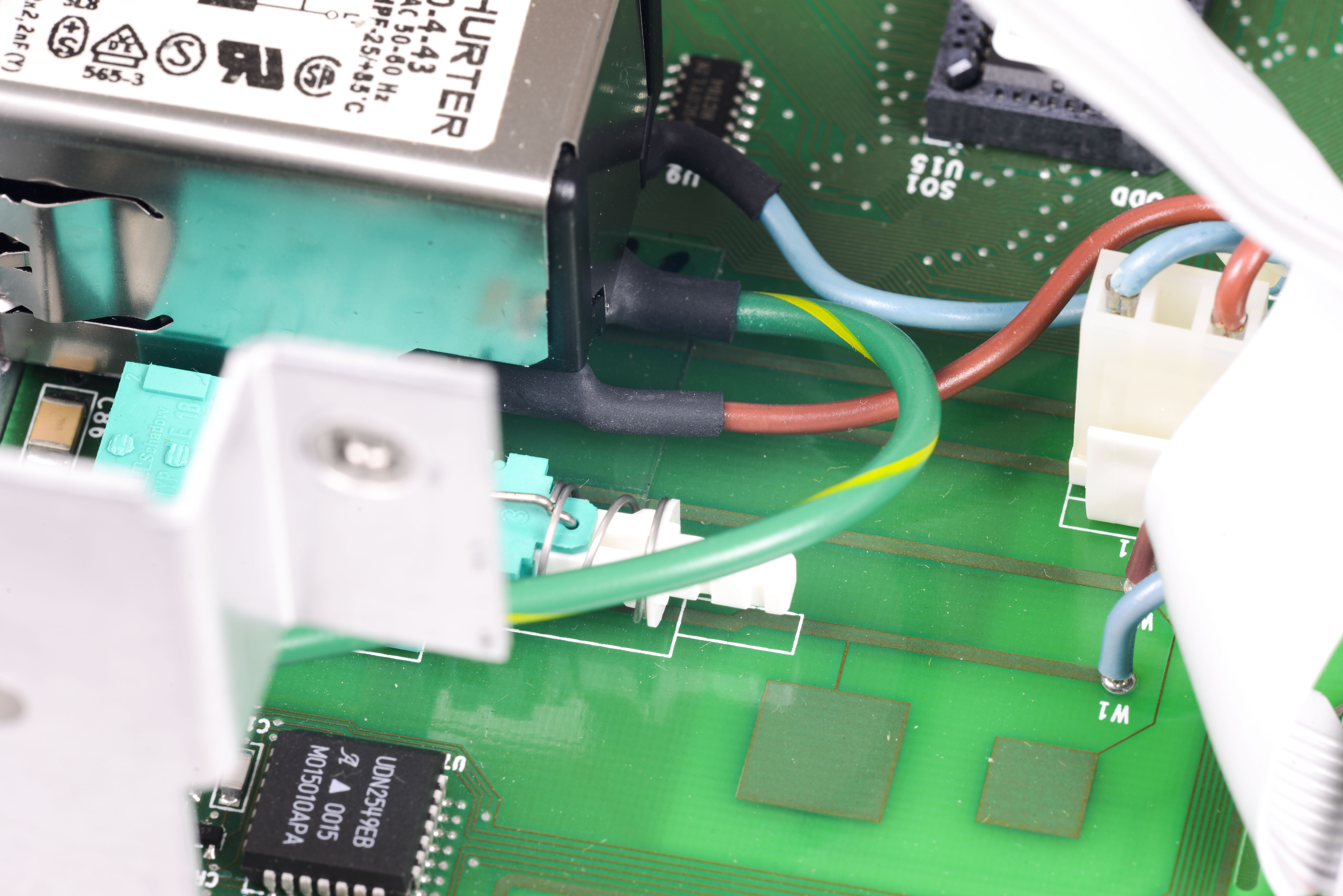
Interesting find – PCB capacitors (?). Maybe it’s used to read mains frequency due to AC coupling, but that’s really just my guess :) Would be interesting to know what are those square pads connected to mains input actually do :)
Mains power supply
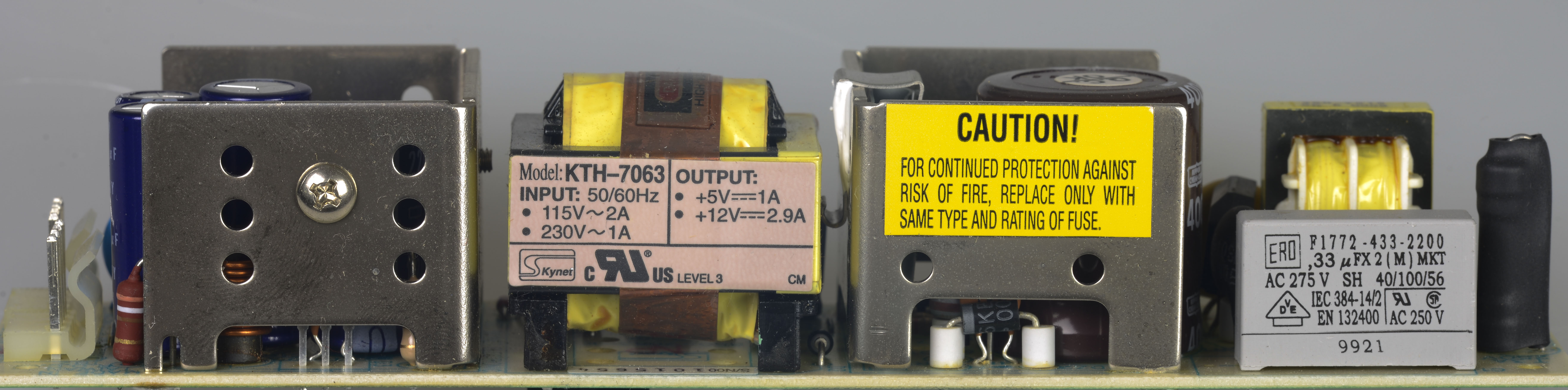
Not much interesting here, it’s KTH-7063 model power supply, probably made by some OEM for Keithley.

Voltage output is 5V 1A and +12V 2.9A.
Front panel and repair
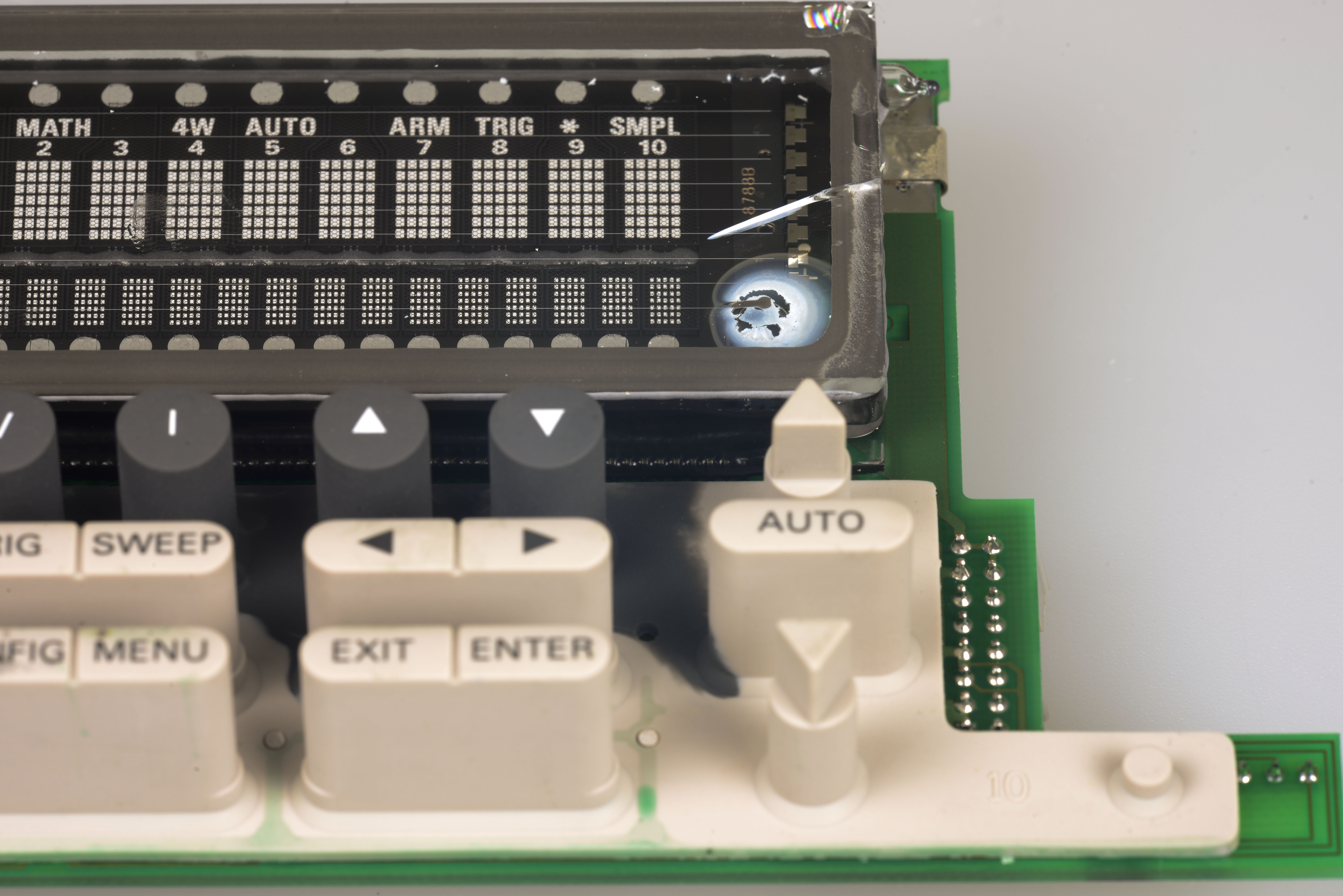
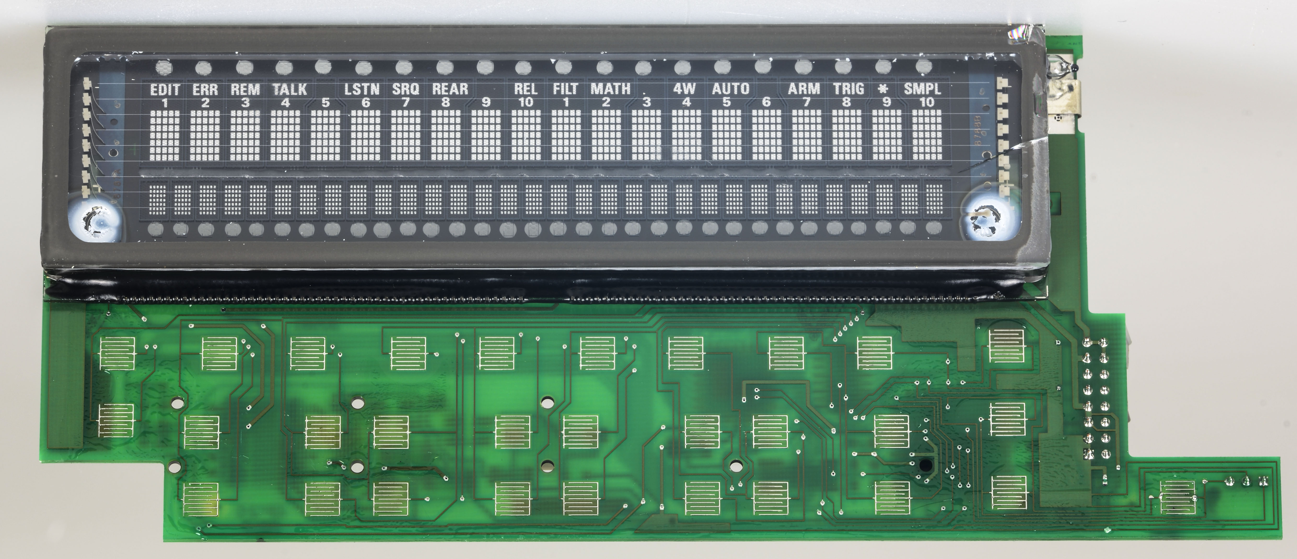
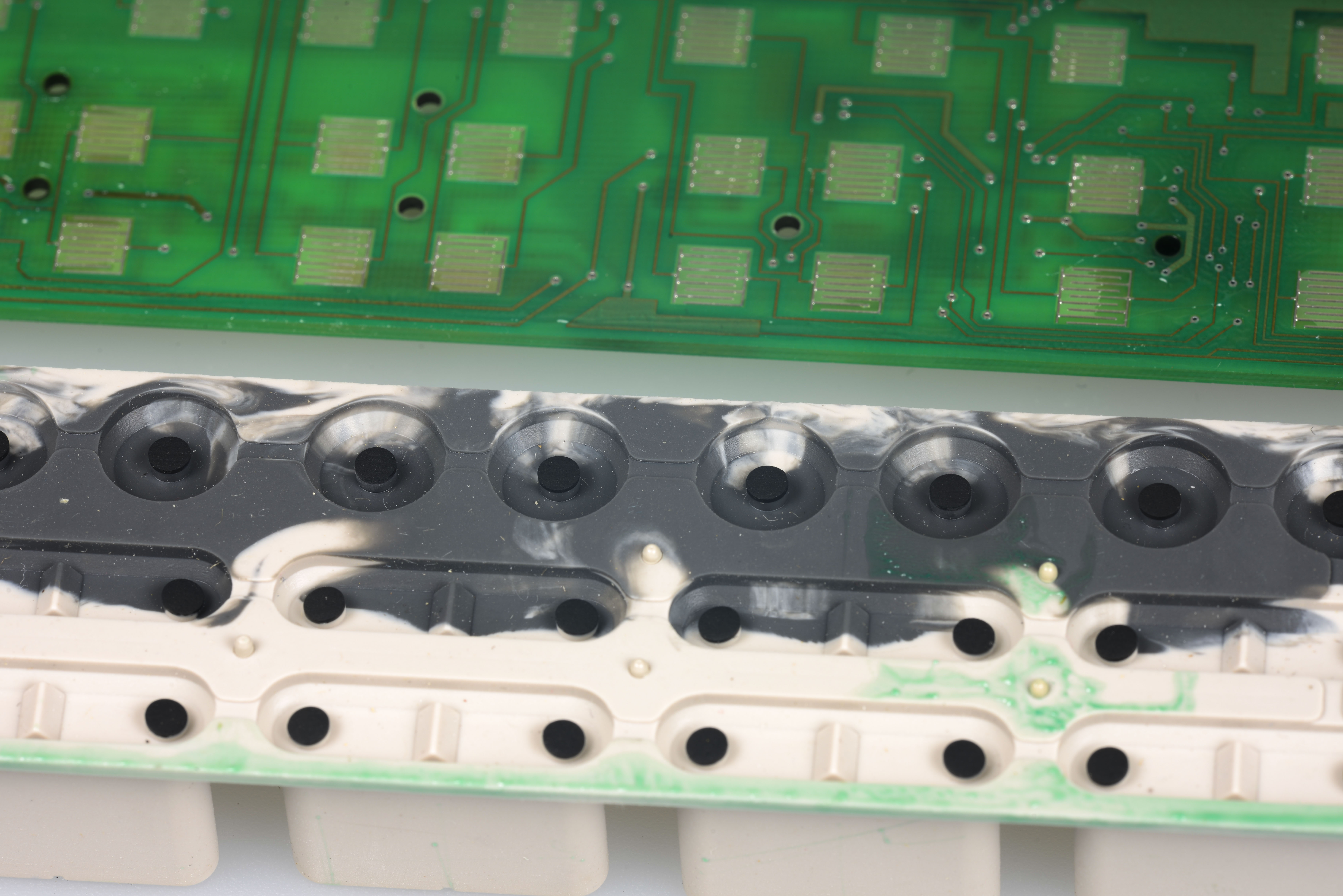
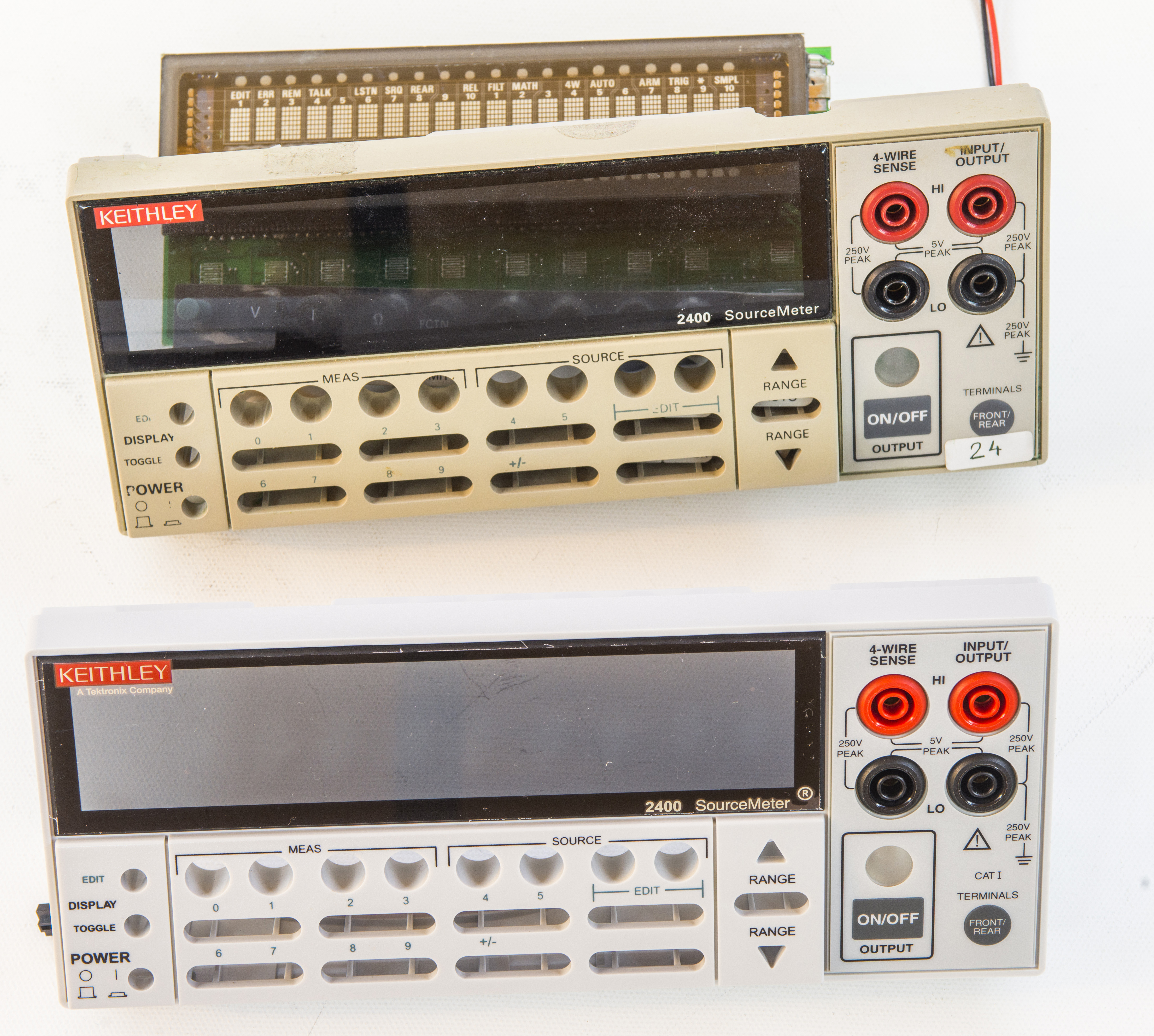
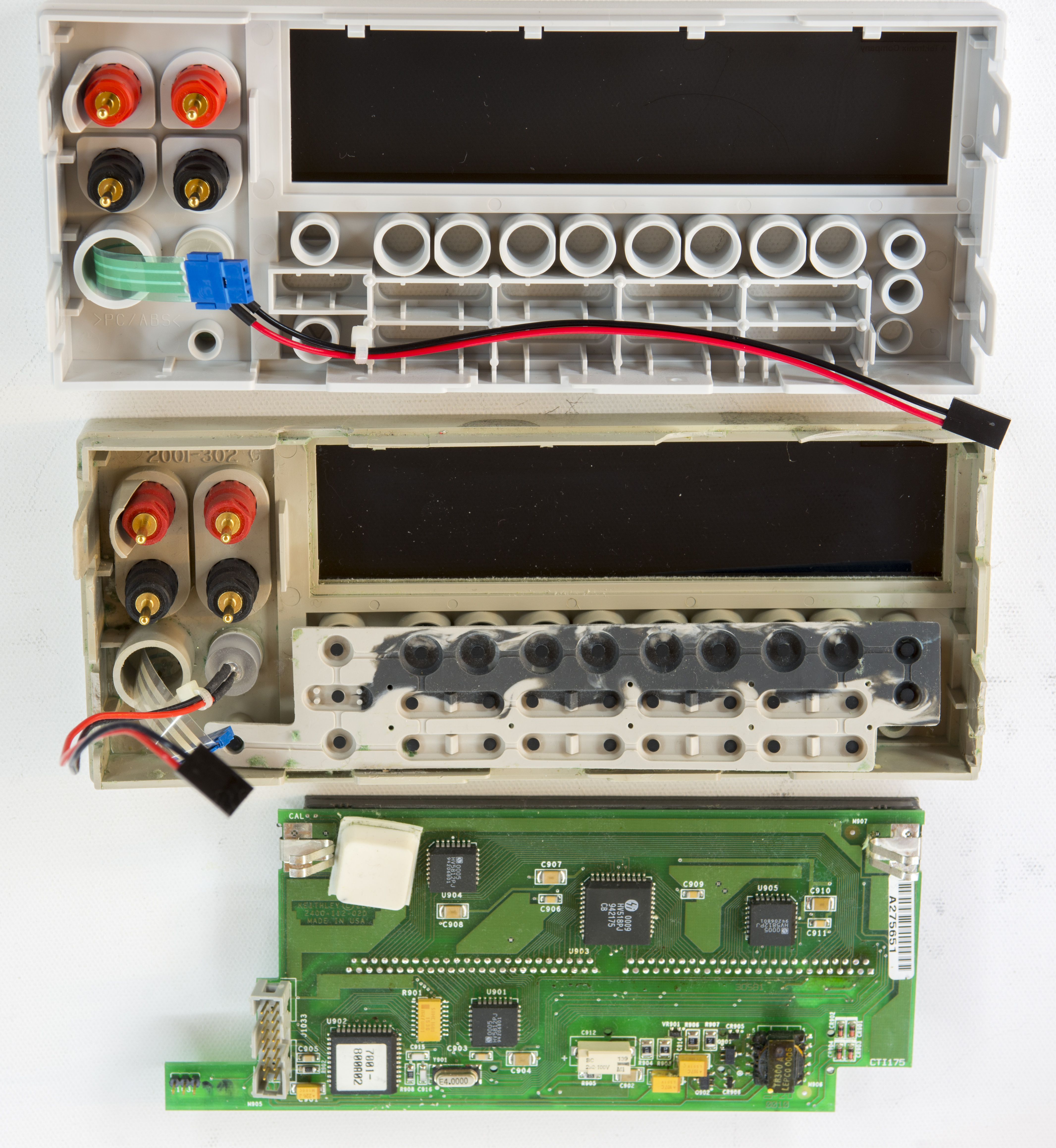
Membrane keypad with rubber keys, just like good old 200x DMM series. This is how i got it, VFD glass broken, magic vacuum is gone. You can see it by white residue getter.
Keypad is covered with same green gunk, but that was easy fix by cleaning with some alcohol.
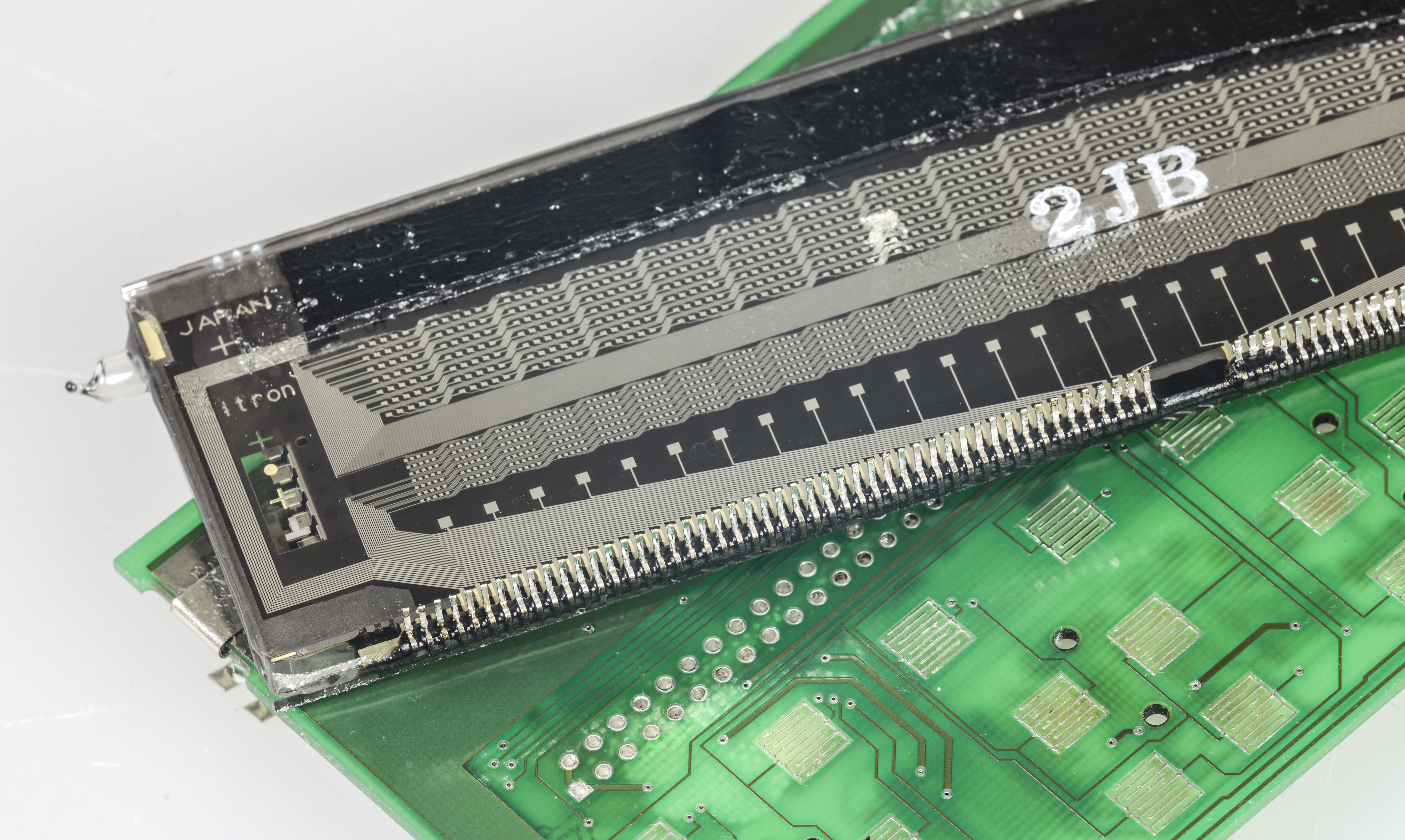
Desoldered VFD, using solder wick to suck all solder. Thanks to little bigger pads, i could manage to free display from PCB relatively easy.
I had one of 2001’s with lots of components missing, so used VFD from it. New VFD ready prior to soldering:
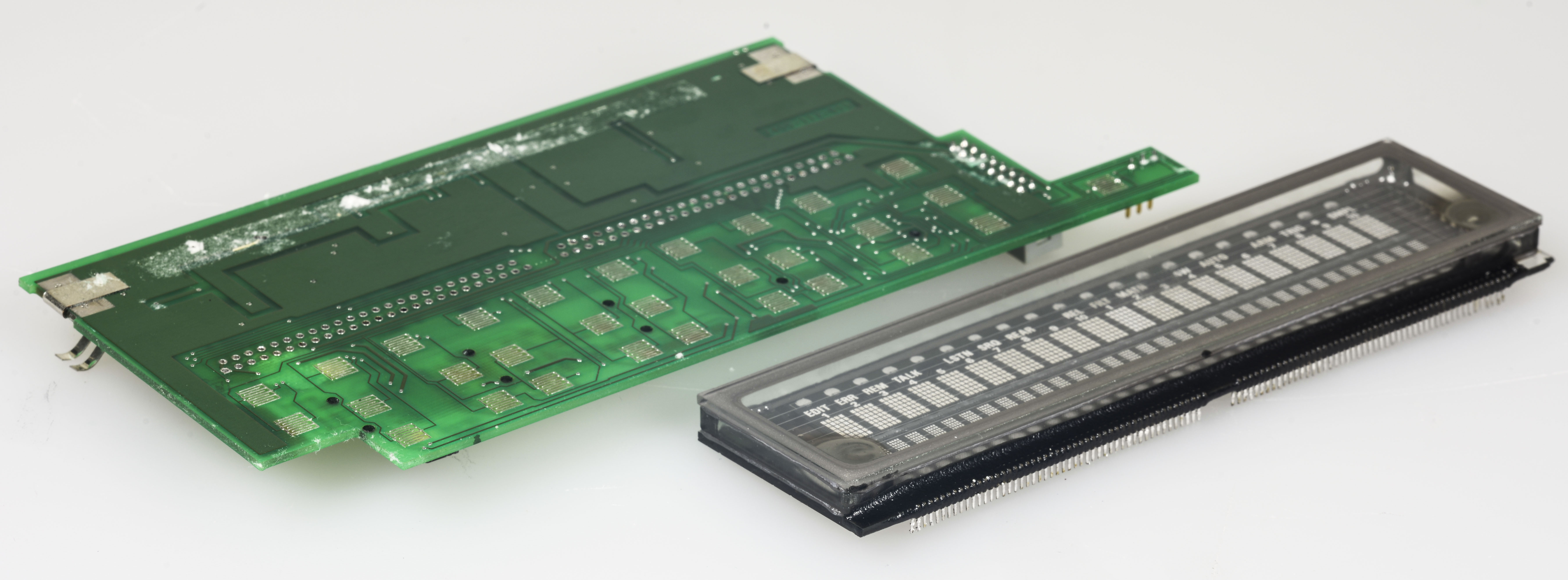
There is minor difference – 2001 VFD had straight row of pins, while 2400 PCB had checker formed pins. Had to do some creative forming to solder new one on 2400 PCB :)
All done, exploded view of all parts before assembly:
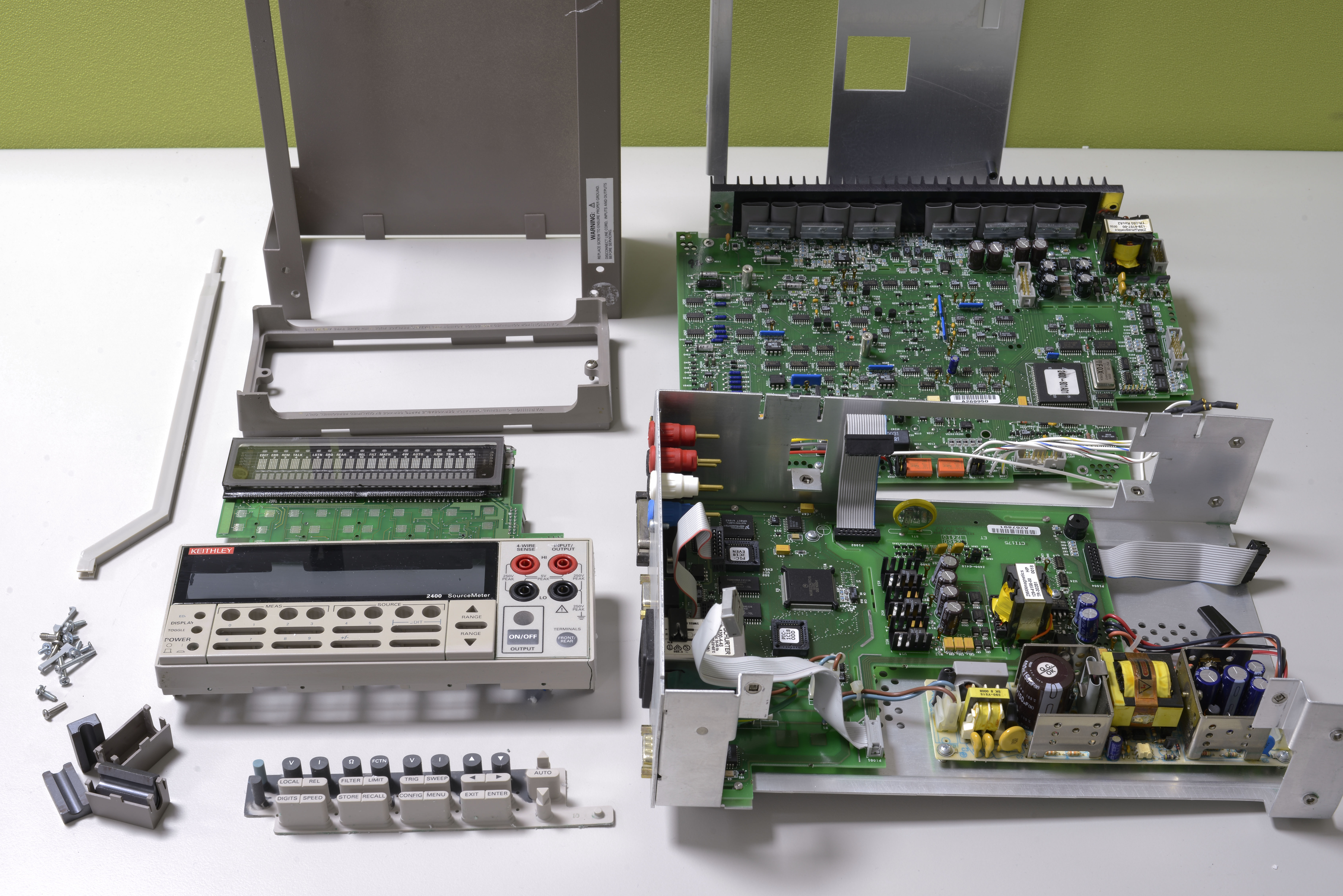
Assembled, first power on:
It works! I already updated firmware to C21, downloaded from Keithley website.
Keithley 2400 front panel plastic replacement


Firmware
Here are some firmware dumps for Keithley 2400 series SMUs.
Supported instruments:
- Keithley Model 2400
- Keithley Model 2410
- Keithley Model 2420
- Keithley Model 2425
- Keithley Model 2430
- Keithley Model 2440
- Keithley Model 2400-C
- Keithley Model 2410-C
- Keithley Model 2420-C
- Keithley Model 2425-C
- Keithley Model 2430-C
- Keithley Model 2440-C
| Firmware version | Combined binary | ODD ROM | EVEN ROM | Original SREC + Release notes |
|---|---|---|---|---|
| Model 24XX C06 Version 51.1, Dec 16 14:52:35 EST 1996 | 24XX Full binary | SREC | ||
| Model 24XX C10 Version 62.1, Jun 4 13:53:13 EDT 1997 | 24XX Full binary | 2400-803-C10 ODD ROM | 2400-804-C10 EVEN ROM | |
| Model 24XX C30 Version 192.1, Mar 17 09:28:23 EST 2006 | 24XX Full binary | SREC ZIP | ||
| Model 24XX C32 Version 199.1, Oct 4 14:19:20 EDT 2010 | 24XX Full binary | 2400-803-C32 ODD ROM | 2400-804-C32 EVEN ROM | SREC ZIP |
| Model 24XX C33 Version 201.1, Mar 31 09:31:47 EST 2015 | 24XX Full binary | 2400-803-C33 ODD ROM | 2400-804-C33 EVEN ROM | SREC ZIP |
Version C33 fixes the issue of powering up with a low line-voltage (90 volts in Japan) for models 2420, 2425, 2430, 2440. Upgrading to this version of firmware will add a 5-second delay to power-up for all models running it.
Also here’s Python app to generate EVEN+ODD ROMs from full little-endian binary file, just in case someone need it.
# xDevs.com Firmware combine tool
# https://xdevs.com/fix/kei2400

import os

with open('2400c32.bin','rb') as a:
    with open('2400-804-C32.bin','wb') as bf, open('2400-803-C32.bin','wb') as cf:
            for cnt in range(0, 262144):
                bf.write ("%s" % a.read(1) )
                cf.write ("%s" % a.read(1) )
It takes input binary and prints it into two files output. Opposite application to combine split files into single little-endian binary available as well.
Calibration
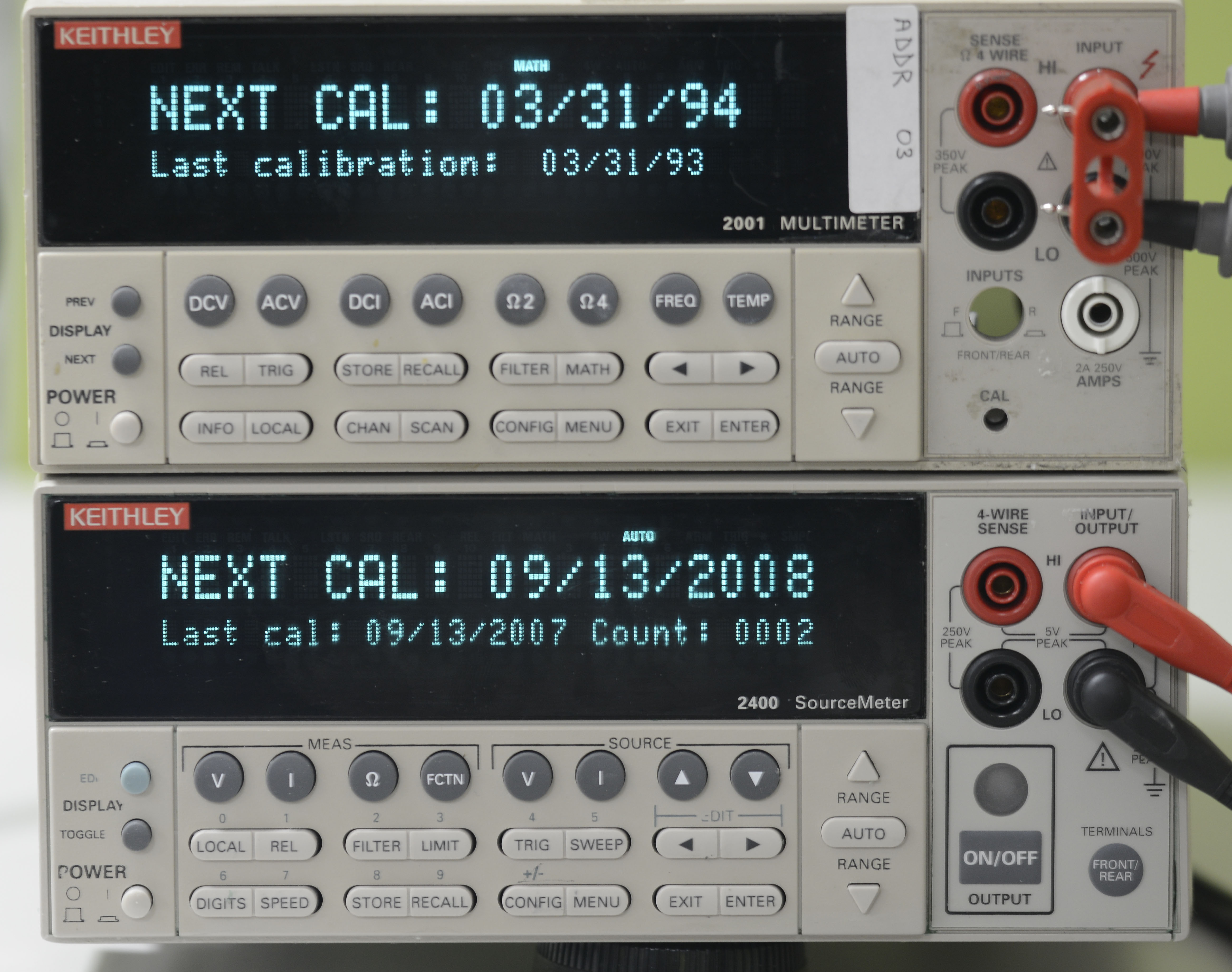
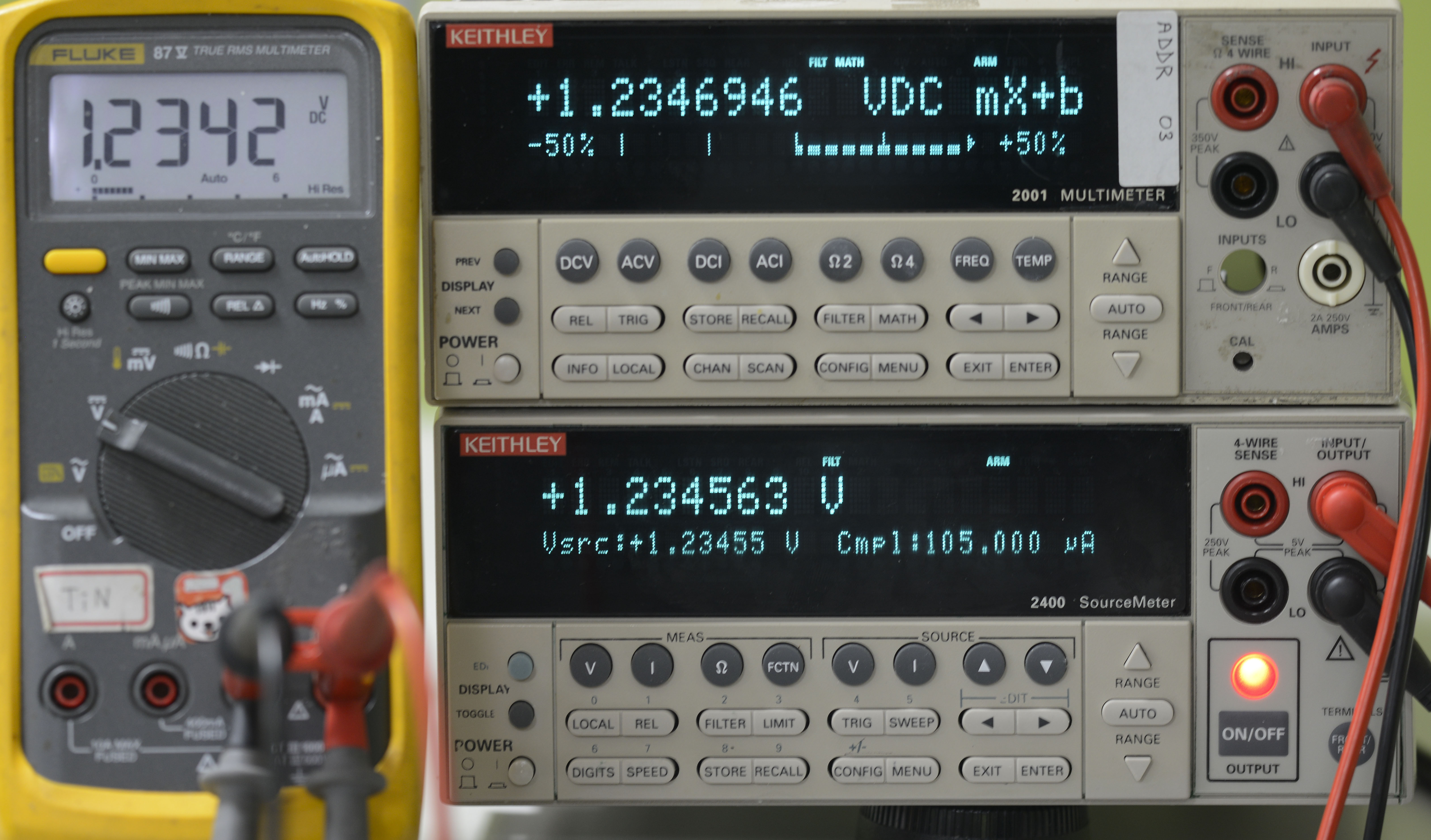
Last cal was 13 September 2007, which is recent, compared my 2001’s 1993 and 1995 years.
Some simple checks, 87V and my first 2001 measuring 1.23455V output from 2400.

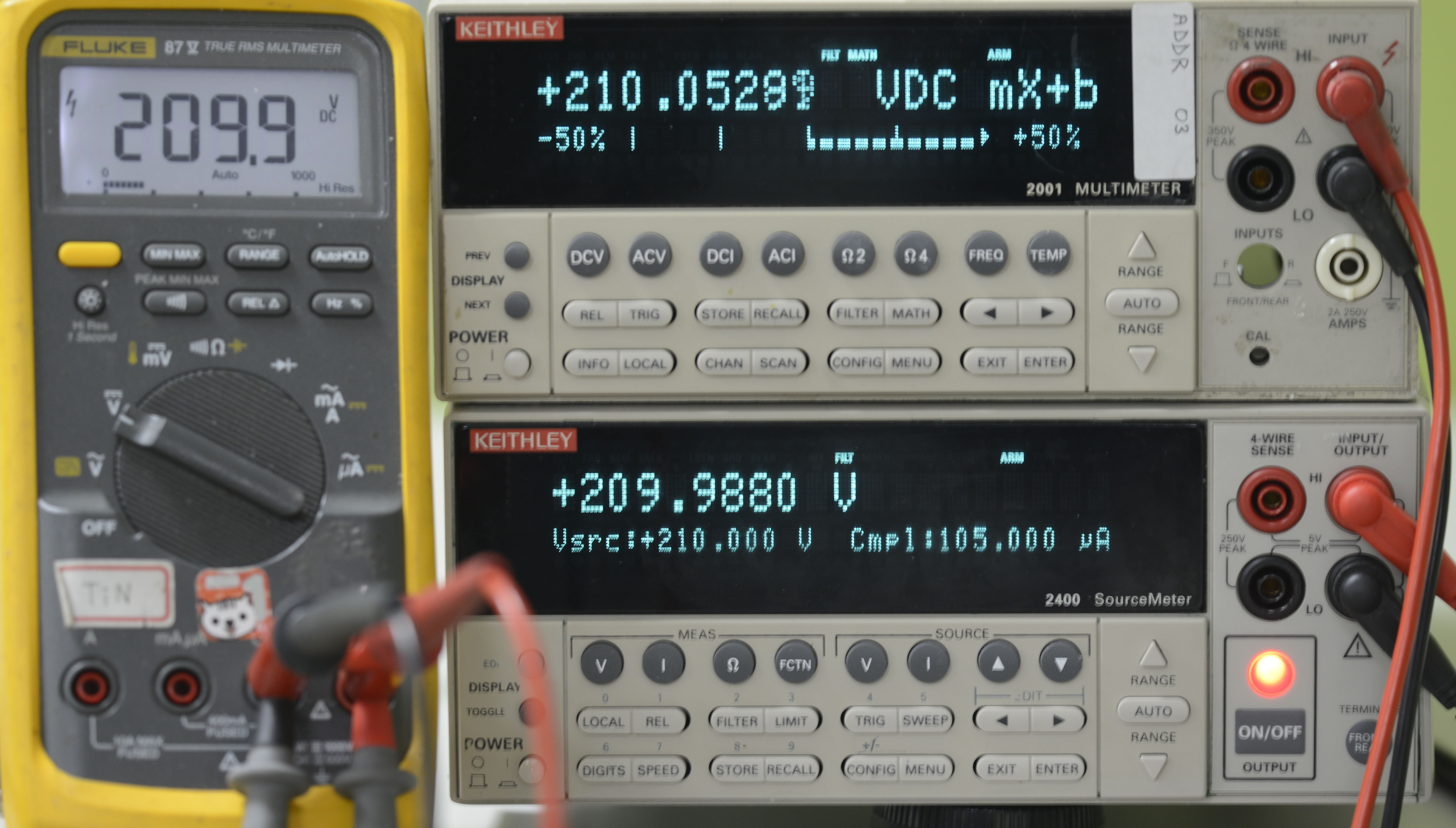
Now since everything seem to be working fine, it’s time to bring this Model 2400 up to spec. To do so I sent unit to official Tektronix calibration service with data requested.
Unit was received back after a week, calibrated 14/01/14

Data report was attached, with items tested and calibrated:
Keithley 2400 Calibration Certificate, as found state, out of tolerance
Unit was failing current source and measure specifications, so had to be adjusted.
Tektronix used next gear as standards:
| Control number | Instrument / standard | Due date calibration |
|---|---|---|
| 5506 | FLUKE 5700A CALIBRATOR | 08-Apr-2014 |
| 7045 | AGILENT 3458A 8½ MULTIMETER | 20-Mar-2014 |
| 8906 | KEITHLEY 2400-756 10 OHM STANDARD | 12-Apr-2014 |
Environment conditions:
Temperature: +24.7°C
Relative Humidity: 46.0 %
Final result after calibration – IN TOLERANCE:
Keithley 2400 Calibration Certificate, as returned state, in tolerance
DIY calibration using HP 3458A
Nothing is permanent, and so is calibration of instruments.
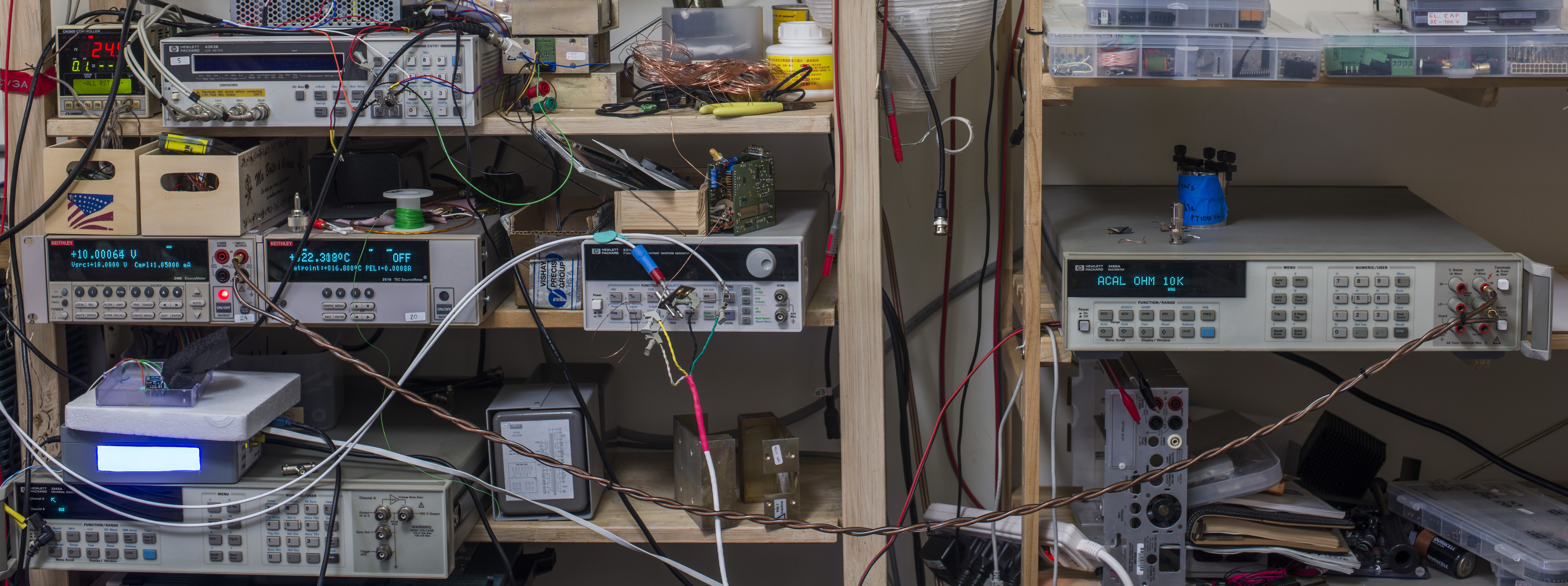
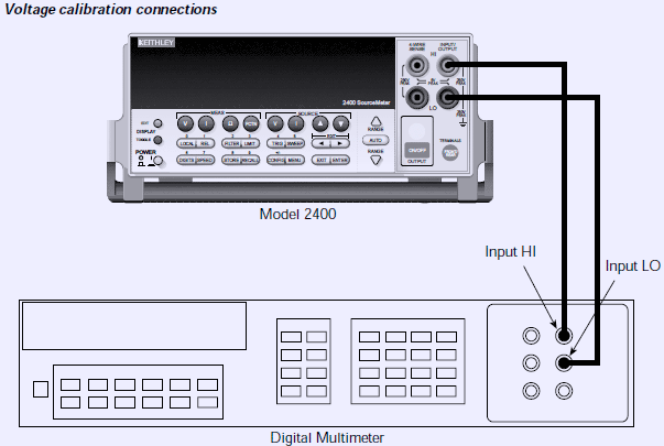
Model 2400 SMU require only reference DMM for calibration and adjustment, in which case I will use HP 3458A 8½-digit DMM. In calibration procedure SMU souring full-scale negative and positive voltages and zero on each range, as well as full-scale positive/negative currents. DMM measures output voltage or current and reading is fed back to SMU as reference. No other external equipment is necessary for this process except pair of leads to connect DMM and SMU.
There are 16 steps for DCV calibration and 28 steps for DCI calibration, with 4 steps for each function range. It’s easy to make mistake and time consuming to do CAL with manual front-panel operation, so I wrote simple calibration program to automate this process. If you need to know details of calibration procedure, you can reference to Keithley Model 2400 Service Manual
Prerequisites:
- Reference HP 3458A with GPIB address 3
- Keithley Model 2400 for calibration with GPIB address 24
- GPIB cable to connect both and GPIB USB dongle (in my case NI USB-GPIB-HS)
- Raspberry Pi (I used 1 Model B, rev.2) running Jessie linux
- linux-gpib configured and working
- Python 2.7 environment configured and working
Python calibration application to download
Calibration Model 2400 application for Raspberry Pi
Calibration Model 2400 application for Raspberry Pi (Python) for vxi11 interface library
Download this Python app into folder on your Pi, for example using wget:
wget https://xdevs.com/doc/Keithley/2400/calsw/cal2400.py
Now make sure both instruments connected to GPIB and USB-GPIB dongle is properly working.
gpib_config
Connect DMM DCV terminals with SMU using good quality test wires. They should be rated to withstand 600V, 3A at least.
Let’s run the calibration app. App will now attempt to detect SMU presence on GPIB address 24, which is hardcoded in the code:
kei2400 = Gpib.Gpib(0,24)
If detection sucessful, message string with unit’s serial number and firmware version will be printed:
Keithley Model 2400 - detected, S/N 0788393, Version: C32 Oct 4 2010 14:20:11/A02 /H/H
Otherwise program will abort and exit.
Now current calibration constants will be read back, just in case you need to monitor their change over time. Example output from my unit shown below:
Pre-cal K2400 Calibration data
    0.2 DCV Range, SENS:DATA? = -1.255853E+00,-7.547438E-05,-1.255865E+00,+0.000000E+00
    0.2 DCV Range, SOUR:DATA? = +3.027005E+05,+9.805352E+02,-3.026938E+05,+9.540547E+02
    2.0 DCV Range, SENS:DATA? = -1.255818E+00,-7.629395E-05,-1.255898E+00,+0.000000E+00
    2.0 DCV Range, SOUR:DATA? = +3.024413E+04,+2.160469E+02,-3.024334E+04,+2.133789E+02
   20.0 DCV Range, SENS:DATA? = -1.255909E+01,-1.522064E-03,-1.255986E+01,+0.000000E+00
   20.0 DCV Range, SOUR:DATA? = +3.024195E+03,+2.183359E+02,-3.024123E+03,+2.110820E+02
  200.0 DCV Range, SENS:DATA? = -1.255817E+02,-1.463318E-02,-1.255900E+02,+0.000000E+00
  200.0 DCV Range, SOUR:DATA? = +3.024431E+02,+2.181953E+02,-3.024344E+02,+2.112461E+02
1.0e-06 DCI Range, SENS:DATA? = -6.258903E-07,-7.969447E-11,-6.258224E-07,+0.000000E+00
1.0e-06 DCI Range, SOUR:DATA? = +6.068293E+10,+2.121250E+02,-6.068410E+10,+2.170313E+02
1.0e-05 DCI Range, SENS:DATA? = -6.294048E-06,-4.620233E-10,-6.294329E-06,+0.000000E+00
1.0e-05 DCI Range, SOUR:DATA? = +6.034448E+09,+2.100234E+02,-6.033632E+09,+2.191016E+02
1.0e-04 DCI Range, SENS:DATA? = -6.273385E-05,-4.249159E-09,-6.273701E-05,+0.000000E+00
1.0e-04 DCI Range, SOUR:DATA? = +6.054307E+08,+2.098086E+02,-6.053455E+08,+2.192617E+02
1.0e-03 DCI Range, SENS:DATA? = -6.261325E-04,-4.319008E-08,-6.261630E-04,+0.000000E+00
1.0e-03 DCI Range, SOUR:DATA? = +6.065957E+07,+2.098047E+02,-6.065106E+07,+2.192695E+02
1.0e-02 DCI Range, SENS:DATA? = -6.275110E-03,-4.488975E-07,-6.275468E-03,+0.000000E+00
1.0e-02 DCI Range, SOUR:DATA? = +6.052646E+06,+2.099297E+02,-6.051750E+06,+2.191328E+02
1.0e-01 DCI Range, SENS:DATA? = -6.279009E-02,-4.447997E-06,-6.279366E-02,+0.000000E+00
1.0e-01 DCI Range, SOUR:DATA? = +6.048887E+05,+2.099453E+02,-6.047995E+05,+2.191445E+02
1.0e+00 DCI Range, SENS:DATA? = -6.287083E+00,-4.602075E-04,-6.287335E+00,+0.000000E+00
1.0e+00 DCI Range, SOUR:DATA? = +6.044879E+04,+8.966484E+02,-6.044157E+04,+9.857813E+02
Now DMM will be detected on GPIB address 3
dmm = dmm(3,dmm_val,"3458A") # GPIB 3
     dmm.exec_idn()
If detection successful, test string will be printed and internal DMM temperature would be read
HP 3458A detected
     TEMP? = 37.5 C
Now user will be prompted to connect DMM DCV input to Model 2400 HI/LO jacks, and app will wait for ENTER key-press to continue.
After user confirmation ACAL ALL will be run on DMM to ensure best accuracy. If you don’t want to run ACAL, comment line 238, dmm.exec_acal() command. ACAL ALL takes 12 minutes to complete.
DCV Calibration step -0.2 mV , measured : -2.000011150E-01 VDC, deviation   5.575 ppm
DCV Calibration step  0.2 mV , measured :  1.999950137E-01 VDC, deviation -24.932 ppm
DCV Calibration step    -2 V , measured : -2.000001226E+00 VDC, deviation   0.613 ppm
DCV Calibration step     2 V , measured :  1.999990515E+00 VDC, deviation  -4.743 ppm
DCV Calibration step   -20 V , measured : -1.999985933E+01 VDC, deviation  -7.033 ppm
DCV Calibration step    20 V , measured :  1.999995167E+01 VDC, deviation  -2.416 ppm
DCV Calibration step -200 V  , measured : -1.999999936E+02 VDC, deviation  -0.032 ppm
DCV Calibration step  200 V  , measured :  1.999976683E+02 VDC, deviation -11.659 ppm
Every step is measured by DMM 10 times and average reading will be used to send back to SMU. Deviation from expected value is printed as well, in ppm scale.
If Model 2400 generate error after any step, calibration will be aborted with error message Keithley 2400 error.
After successful DCV calibration without errors user will be prompted to connect DMM DCI current input to Model 2400 HI/LO jacks, and app will wait for ENTER keypress to continue.
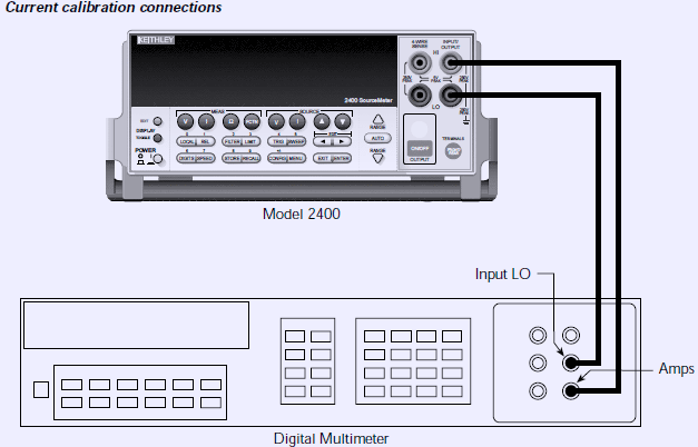
DCI Calibration step   -1 uA , measured : -9.999932723E-07 ADC, deviation  -6.728 ppm
DCI Calibration step    1 uA , measured :  9.999700048E-07 ADC, deviation -29.995 ppm
DCI Calibration step  -10 uA , measured : -9.999961705E-06 ADC, deviation  -3.829 ppm
DCI Calibration step   10 uA , measured :  9.999932024E-06 ADC, deviation  -6.798 ppm
DCI Calibration step -100 uA , measured : -9.999879347E-05 ADC, deviation -12.065 ppm
DCI Calibration step  100 uA , measured :  9.999867260E-05 ADC, deviation -13.274 ppm
DCI Calibration step   -1 mA , measured : -9.999954493E-04 ADC, deviation  -4.551 ppm
DCI Calibration step    1 mA , measured :  9.999928871E-04 ADC, deviation  -7.113 ppm
DCI Calibration step  -10 mA , measured : -9.999891116E-03 ADC, deviation -10.888 ppm
DCI Calibration step   10 mA , measured :  9.999946257E-03 ADC, deviation  -5.374 ppm
DCI Calibration step -100 mA , measured : -1.000001955E-01 ADC, deviation   1.955 ppm
DCI Calibration step  100 mA , measured :  9.999891230E-02 ADC, deviation -10.877 ppm
DCI Calibration step    -1 A , measured : -9.999968151E-01 ADC, deviation  -3.185 ppm
DCI Calibration step     1 A , measured :  9.999915013E-01 ADC, deviation  -8.499 ppm
Every step is measured by DMM 10 times and average reading will be used to send back to SMU. Deviation from expected value is printed as well, in ppm scale.
Now calibration complete, and app will ask to save calibration data permanently to Model 2400’s EEPROM? User confirmation will be asked by prompt. If you want to abort calibration, press CTRL-C now.
| Press Enter to save calibration. This operation cannot undo! |
If data look correct, you can press ENTER key to save calibration and proceed with test.
After this step old calibration will be altered and cannot be recovered.
Test results of my unit calibration in 2016 run above summarized in table below:
| Function | SMU | DMM reading | ppm Dev | DMM spec | SMU 1year spec | Min | Max |
|---|---|---|---|---|---|---|---|
| DCV | -0.2 V | -0.2000011150 | 5.575 | ±15 | 0.02% + 600µV | -0.20064 V | -0.19936 V |
| DCV | 0.2 V | 0.1999950137 | -24.932 | ±15 | 0.02% + 600µV | 0.19936 V | 0.20064 V |
| DCV | -2 V | -2.000001226 | 0.613 | ±6 | 0.02% + 600µV | -2.00100 V | -1.99900 V |
| DCV | 2 V | 1.999990515 | -4.743 | ±6 | 0.02% + 600µV | 1.99900 V | 2.00100 V |
| DCV | -20 V | -19.99985933 | -7.033 | ±9 | 0.02% + 2.4mV | -20.00640 V | -19.99360 V |
| DCV | 20 V | 19.99995167 | -2.416 | ±9 | 0.02% + 2.4mV | 19.99360 V | 20.00640 V |
| DCV | -200 V | -199.9999936 | -0.032 | ±7 | 0.02% + 24mV | -200.06400 V | -199.93600 V |
| DCV | 200 V | 199.9976683 | -11.659 | ±7 | 0.02% + 24mV | 199.93600 V | 200.06400 V |
| DCI | -1.00µA | -9.999932723 × 10⁻⁷ | -6.728 | ±55 | 0.035% + 600pA | -1.00095µA | -0.99905µA |
| DCI | 1.00µA | 9.999700048 × 10⁻⁷ | -29.995 | ±55 | 0.035% + 600pA | 0.99905µA | 1.00095µA |
| DCI | -10.0µA | -9.999961705 × 10⁻⁶ | -3.830 | ±25 | 0.033% + 2nA | -10.0053µA | -9.99470µA |
| DCI | 10.0µA | 9.999932024 × 10⁻⁶ | -6.798 | ±25 | 0.033% + 2nA | 9.99470µA | 10.0051µA |
| DCI | -100 µA | -9.999879347 × 10⁻⁵ | -12.065 | ±23 | 0.031% + 20nA | -100.051µA | -99.9490µA |
| DCI | 100 µA | 9.999867260 × 10⁻⁵ | -13.274 | ±23 | 0.031% + 20nA | 99.9490µA | 100.051µA |
| DCI | -1.00 mA | -9.999954493 × 10⁻⁴ | -4.551 | ±20 | 0.034% + 200nA | -1.00054 mA | -0.999460 mA |
| DCI | 1.00 mA | 9.999928871 × 10⁻⁴ | -7.113 | ±20 | 0.034% + 200nA | 0.999460 mA | 1.00054 mA |
| DCI | -10.0 mA | -9.999891116 × 10⁻³ | -10.888 | ±20 | 0.045% + 2µA | -10.0065 mA | -9.99350 mA |
| DCI | 10.0 mA | 9.999946257 × 10⁻³ | -5.374 | ±20 | 0.045% + 2µA | 9.99350 mA | 10.0065 mA |
| DCI | -100 mA | -1.000001955 × 10⁻¹ | 1.955 | ±35 | 0.066% + 20µA | -100.086 mA | -99.9140 mA |
| DCI | 100 mA | 9.999891230 × 10⁻² | -10.877 | ±35 | 0.066% + 20µA | 99.9140 mA | 100.086 mA |
| DCI | -1 A | -0.9999968151 | -3.185 | ±110 | 0.27 % + 900µA | -1.003600 A | -0.996400 A |
| DCI | 1 A | 0.9999915013 | -8.499 | ±110 | 0.27 % + 900µA | 0.996400 A | 1.003600 A |
Conclusion
Hope you enjoyed reading. If anybody have idea what to try or show more on this SourceMeter, feel free to shoot in comments.
Projects like this are born from passion and a desire to share how things work. Education is the foundation of a healthy society - especially important in today's volatile world. xDevs began as a personal project notepad in Kherson, Ukraine back in 2008 and has grown with support of passionate readers just like you. There are no (and never will be) any ads, sponsors or shareholders behind xDevs.com, just a commitment to inspire and help learning. If you are in a position to help others like us, please consider supporting xDevs.com’s home-country Ukraine in its defense of freedom to speak, freedom to live in peace and freedom to choose their way. You can use official site to support Ukraine – United24 or Help99. Every cent counts.
Modified: June 19, 2019, 10:21 p.m.