Contents
Intro and specifications
Key features and spectifications:
- Input resistance: 20 kΩ for 100:1 and 10000:1 ratios, 200 kΩ for 1000:1 and 100000:1 ratios
- Output resistance: 200 Ω for 100:1 and 10000:1 ratios, 2 Ω for 1000:1 and 100000:1 ratios
- Overload protection: Max input 20VDC, protected up to 1000V with current <150mA
- Controls both polarity and ratio
- Special low thermal output connector, mates with Keithley 1506, 1507, 1481 and 1482 cables
| Divider Ratio | Accuracy (1y, 23°C ±1) | TC (18-28 °C) | Output noise, 0.1Hz BW | Thermal drift |
|---|---|---|---|---|
| 102:1 | ± 35 ppm | 2 ppm/°C | 10 nVPK-PK | 10 nV |
| 103:1 | ± 35 ppm | 2 ppm/°C | 10 nVPK-PK | 10 nV |
| 104:1 | ± 100 ppm | 10 ppm/°C | 1 nVPK-PK | 3 nV |
| 105:1 | ± 100 ppm | 10 ppm/°C | 1 nVPK-PK | 3 nV |
Table 1. Keithley 262 specifications
Accuracy specified with respect to output terminals, and thermal drift for ambient temperature change below 1°C/hour.
Manuals and spec document
Model 262 Low Thermal Voltage Divider, Instruction manual, May 2000, Rev.D
Model 262 old specification sheets
Disassembly and repair
Divider is rather bulky 2kg (4½ lbs) metal box, and few controls on top side and connectors on front side.

Image 1: Model 262 front side
Divider have four fixed division settings, selectable by stiff rotary switch on the left side. Polarity of the signal can be selected both ways. This can be useful for thermal offsets cancellation and linearity tests.
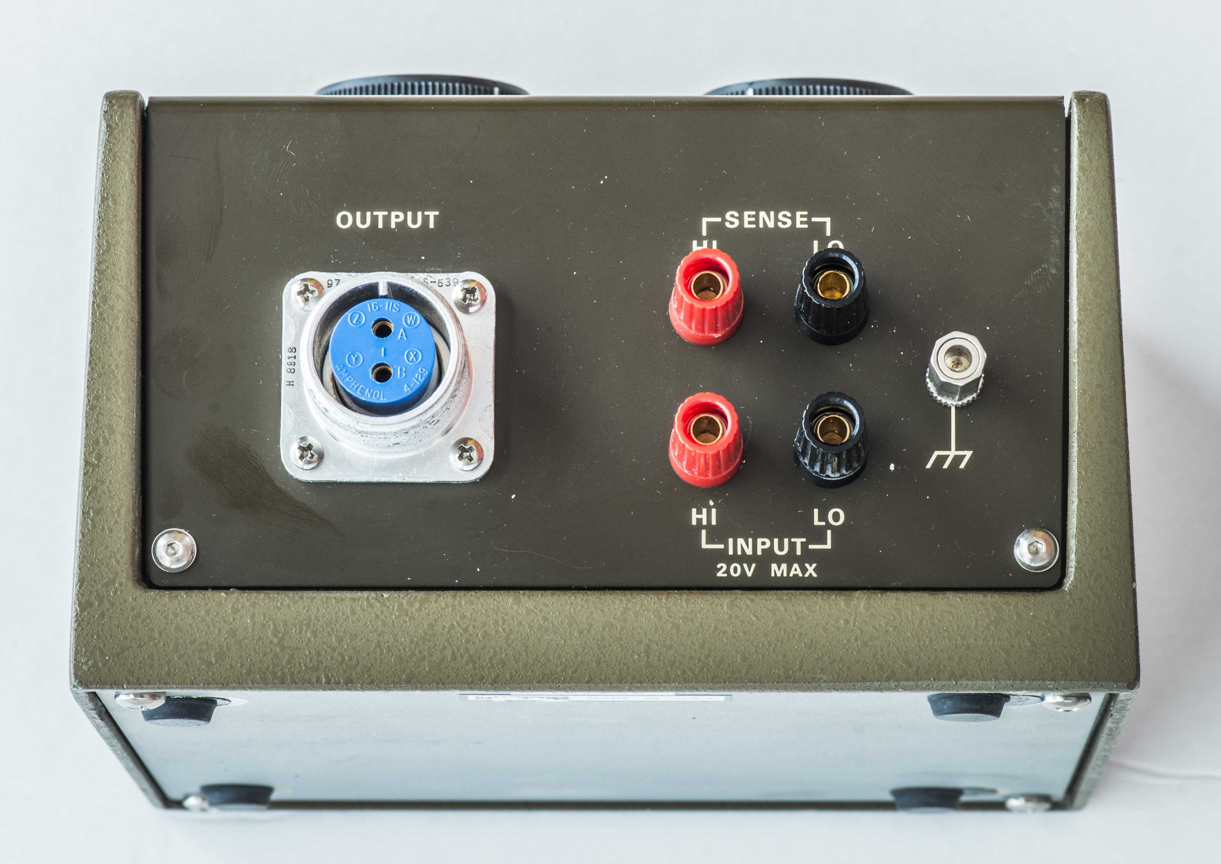
Image 2: Connectors
Input connectors are copper binding posts, which can accept both banana-type and spade lug cables. Shield post is tied to chassis of the divider. Four wire connection allow to cancel cable errors on input voltage.
Output is special (and expensive) low-thermal heavy duty connector, very similar to one used in Keithley 181, 182 and similar nanovoltmeters.
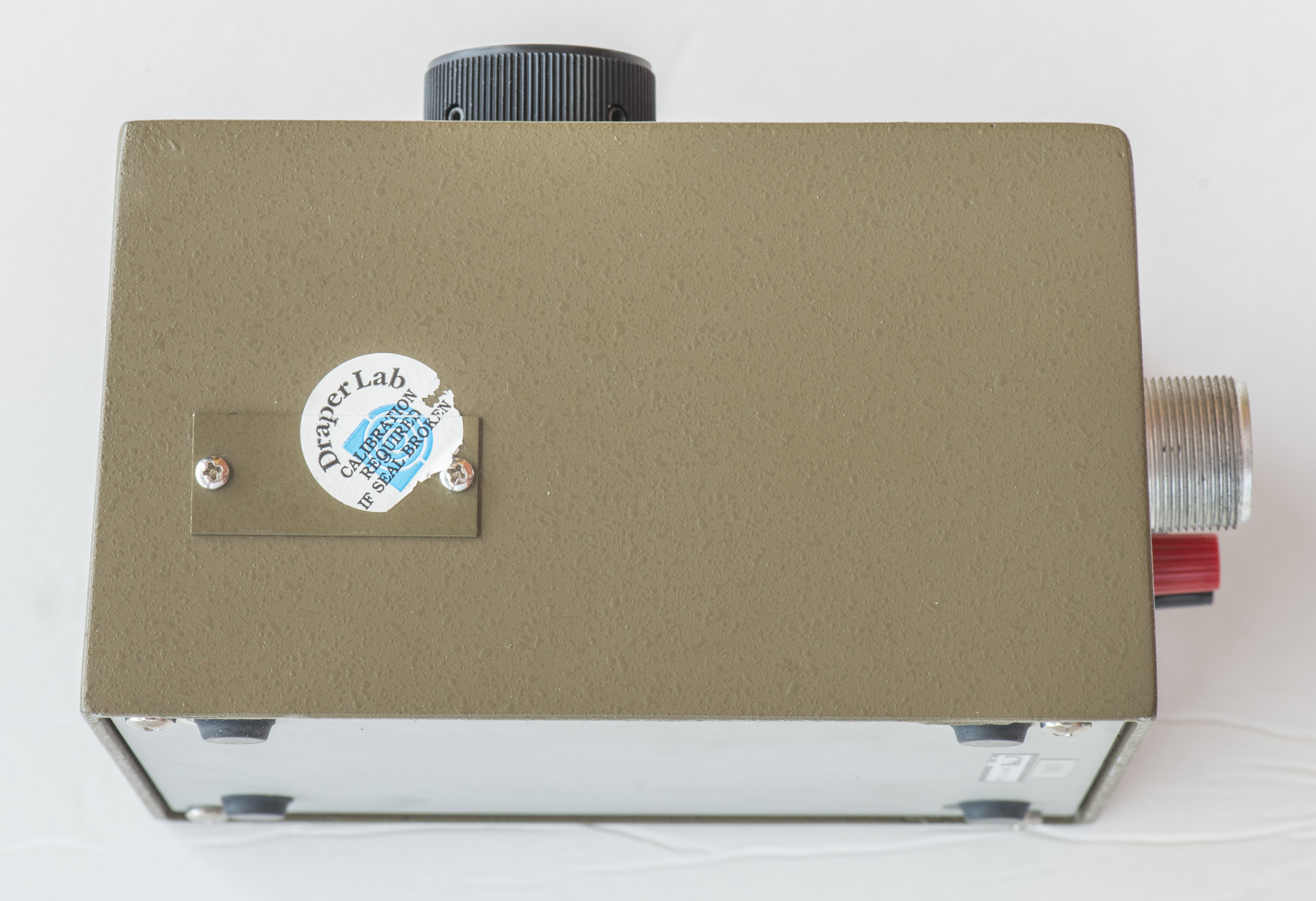
Image 3: Calibration port
Little window with metal cover is present on left side of the divider chassis. This allow to adjust divider and calibrate it’s output voltage. Calibration procedure is listed in instruction manuals as well.
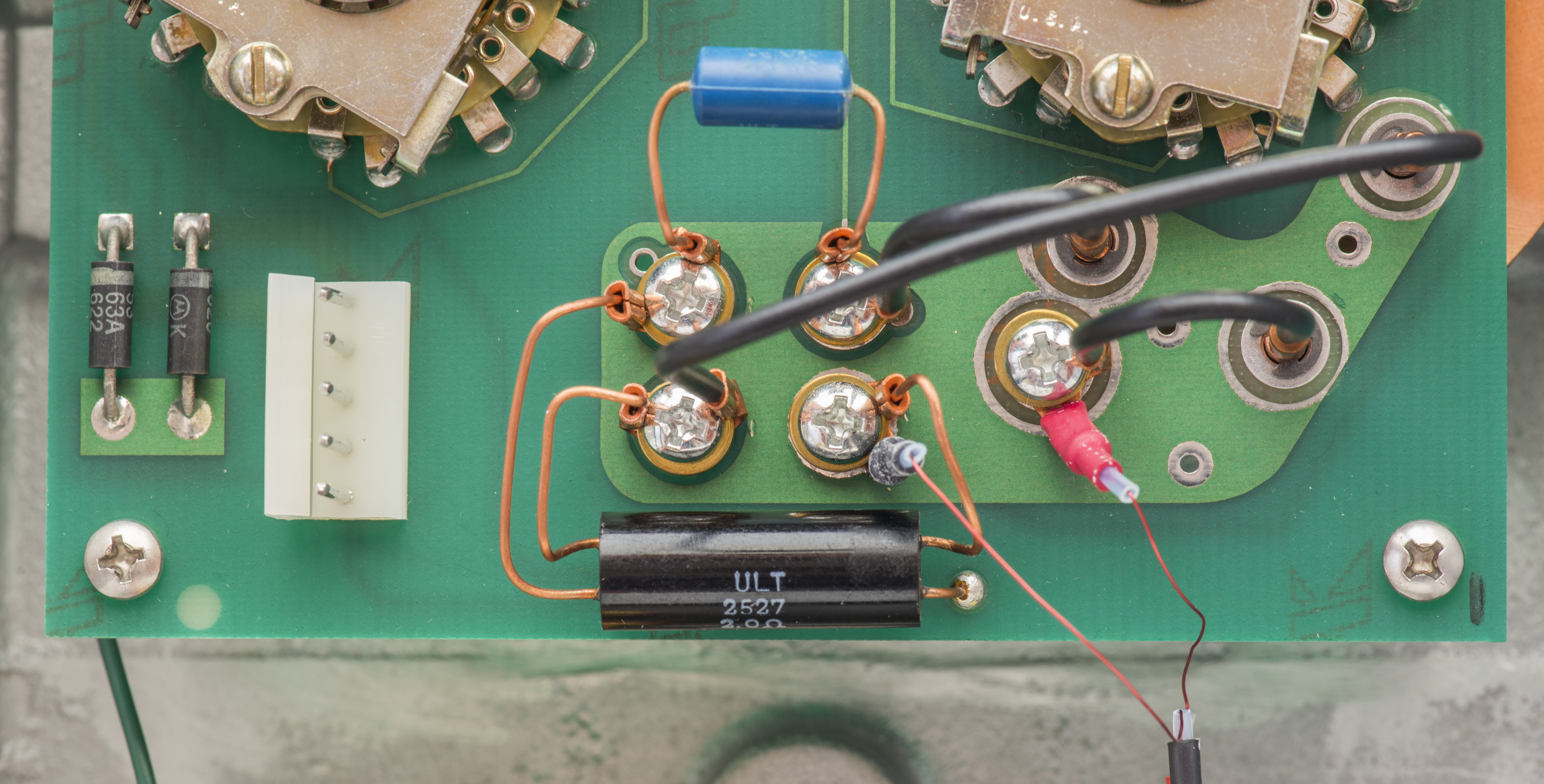
Image 4: Output low-thermal resistor connection
After removal of 4 screws on bottom cover, simple but carefully designed PCB is revealed. Input signal is connected to 5-pin connector and protected by two diodes in opposite polarity. Output resistors are not soldered, but crimped to copper lugs and bolted down to PCB exposed copper directly. On nanovolt levels solder easily can cause forming of unwanted thermocouples, so copper-copper connection method is important here.

Image 5: Connectors wiring
Connectors are nicely wired. Thin bare copper wire used to connect output signal to the bulky port.
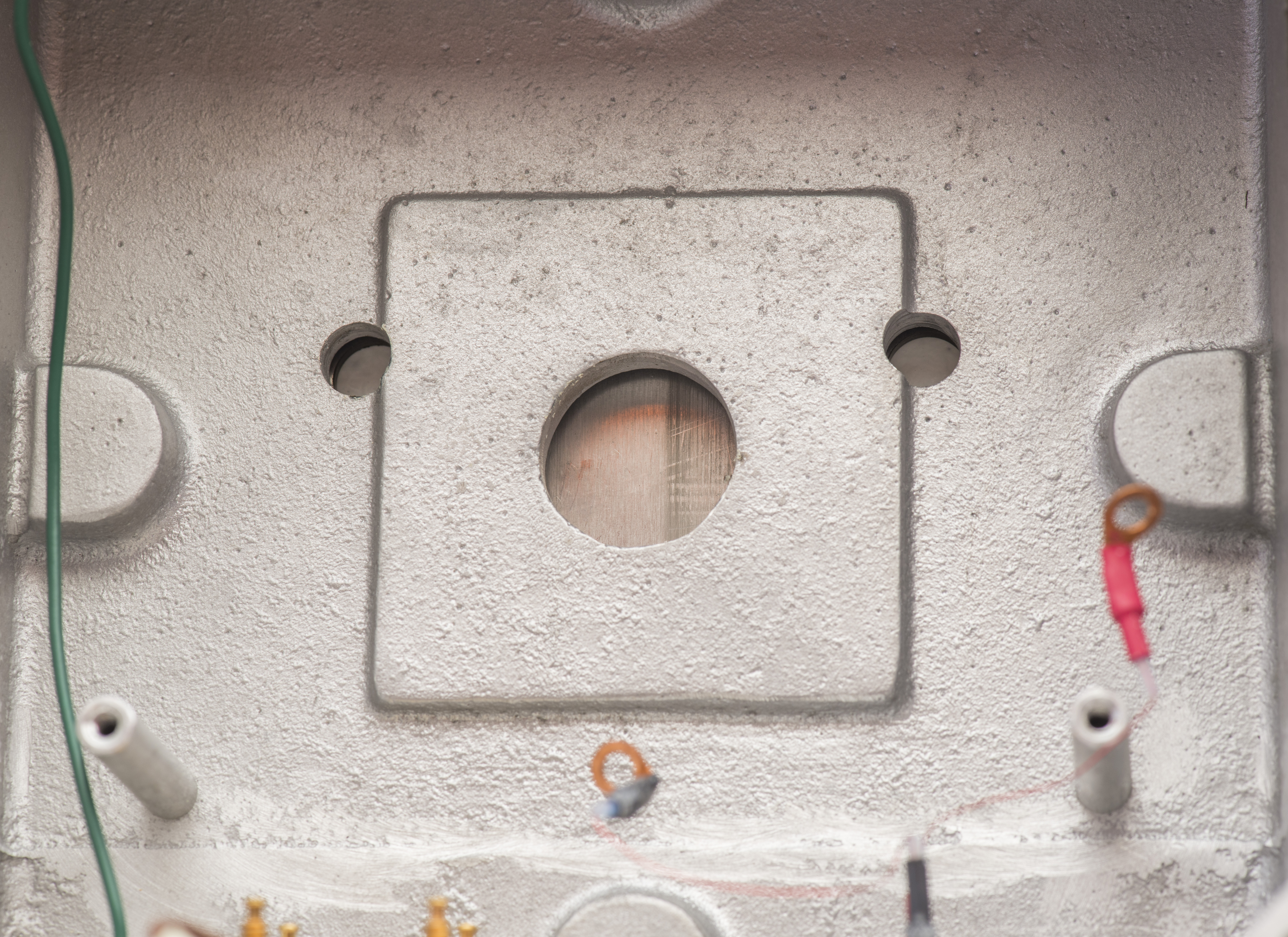
Image 6: Cast metal chassis
Metal chassis is thick, made by casting aluminum. That helps to smooth down thermal variations a bit, as more metal mass have more thermal capacity.

Image 7: Remove output wiring for disassembly
Wiring need to be removed for further teardown. After that and removing 4 mount screws we can take a look on other side of PCB.
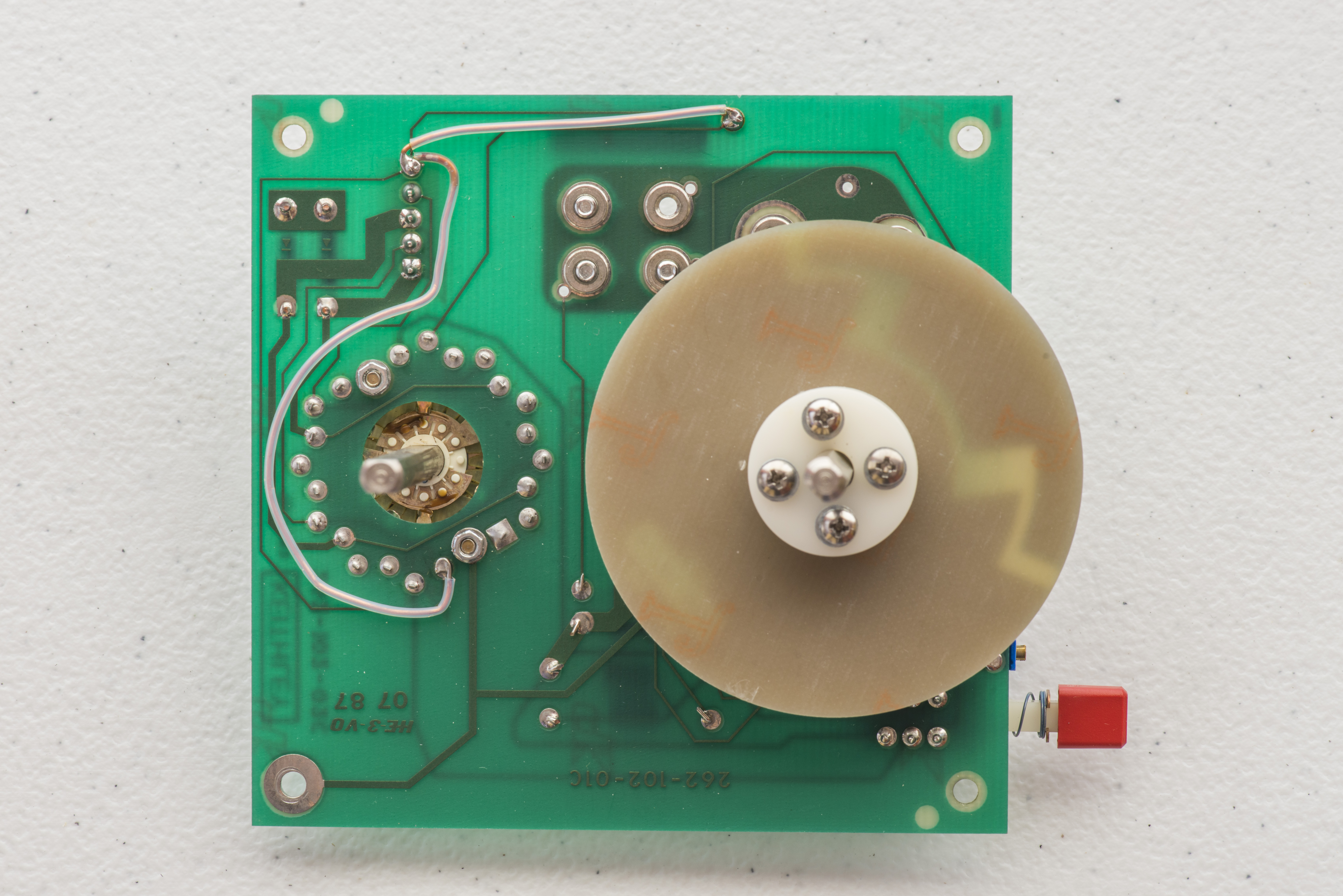
Image 8: Bottom side of the board assembly
High-side resistors are located on top side of the board. Keithley Model 262 PCB marked as 262-102-02C, meaning it’s Rev.C, designed around 1982.
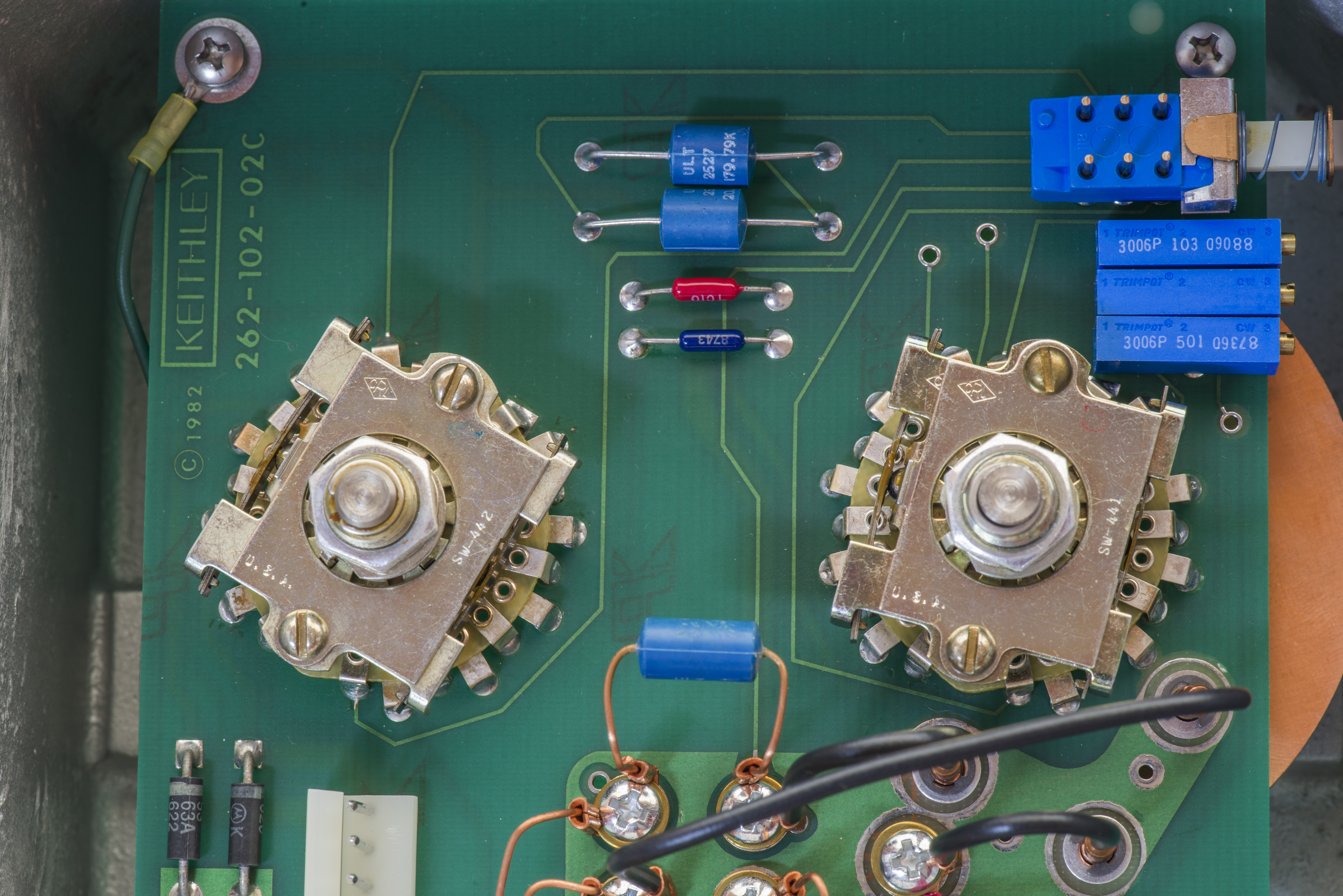
Image 9: PCB review
Quick check with Fluke 87V ensured all resistors have proper values. No service required there.
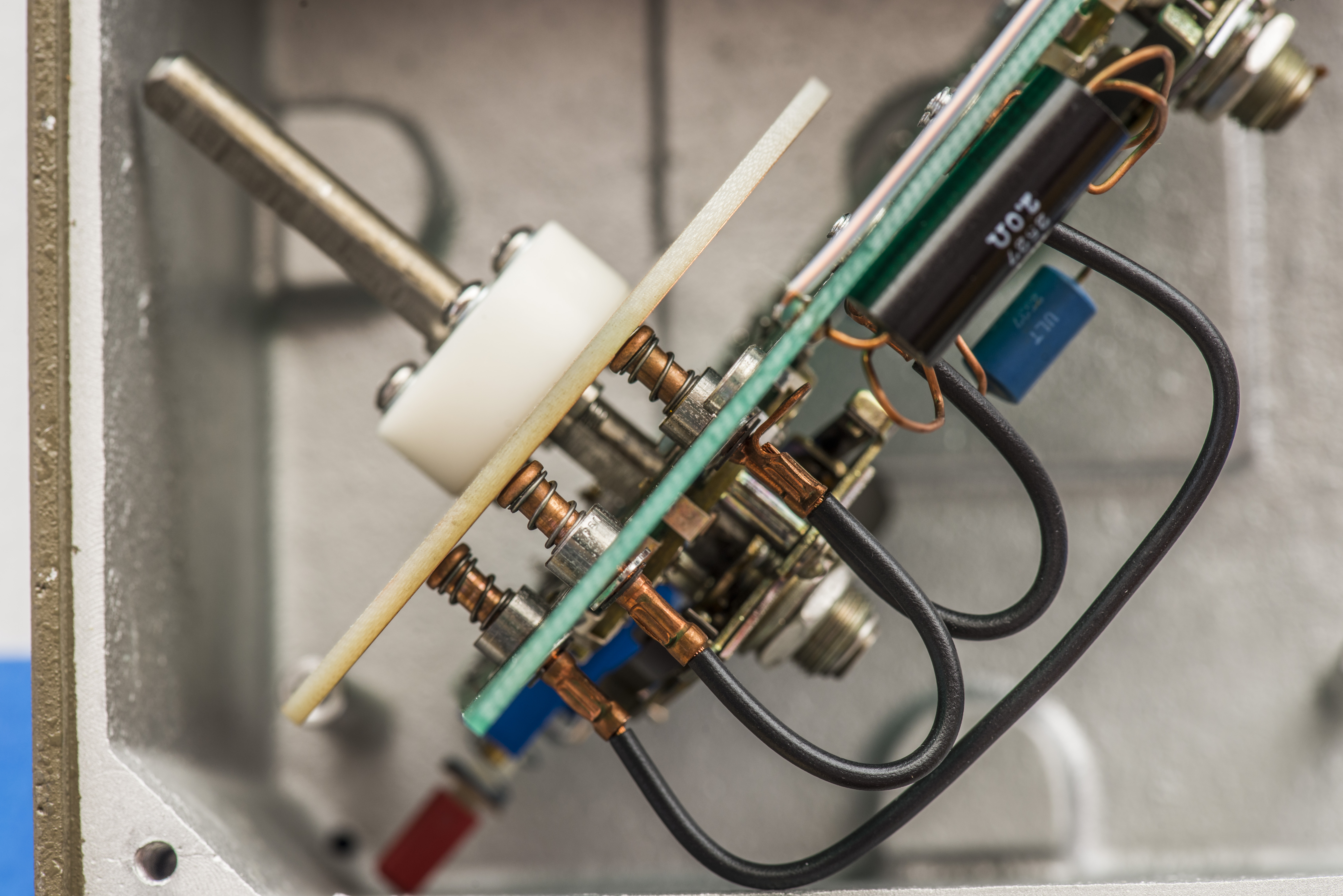
Image 10: Spring contacts for ratio switch disk
Division ratio is done by rather interesting construction of bare copper PCB disk, fixed on the switch shaft. It’s held in place by thick PTFE spacer. Contacts and disc surface are unplated bare copper. Instruction manual recommends to keep disk spaced around 0.375” – 0.400” from PCB surface for proper pressure on contacts.
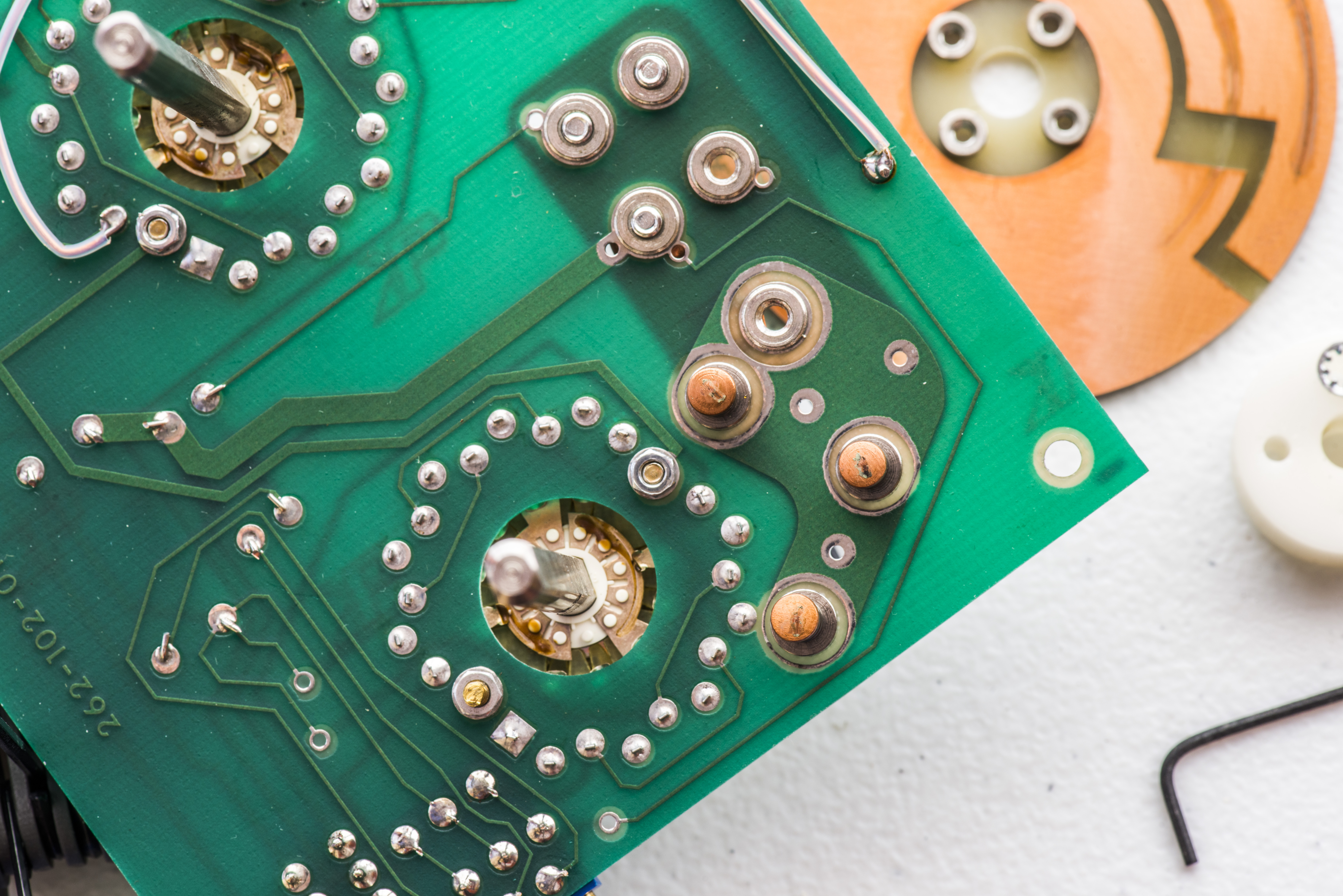
Image 11: Dirty contacts
After removal of disk contacts surface had some green gunk and dirt on them and required just minor cleaning with very fine sandpaper.

Image 12: Disk uncleaned
Disk needed same treatment with 4000 grit sand-paper. After getting nice copper shine it was cleaned with fresh IPA. Very little amount of contact lub was applied on the surface afterwards.
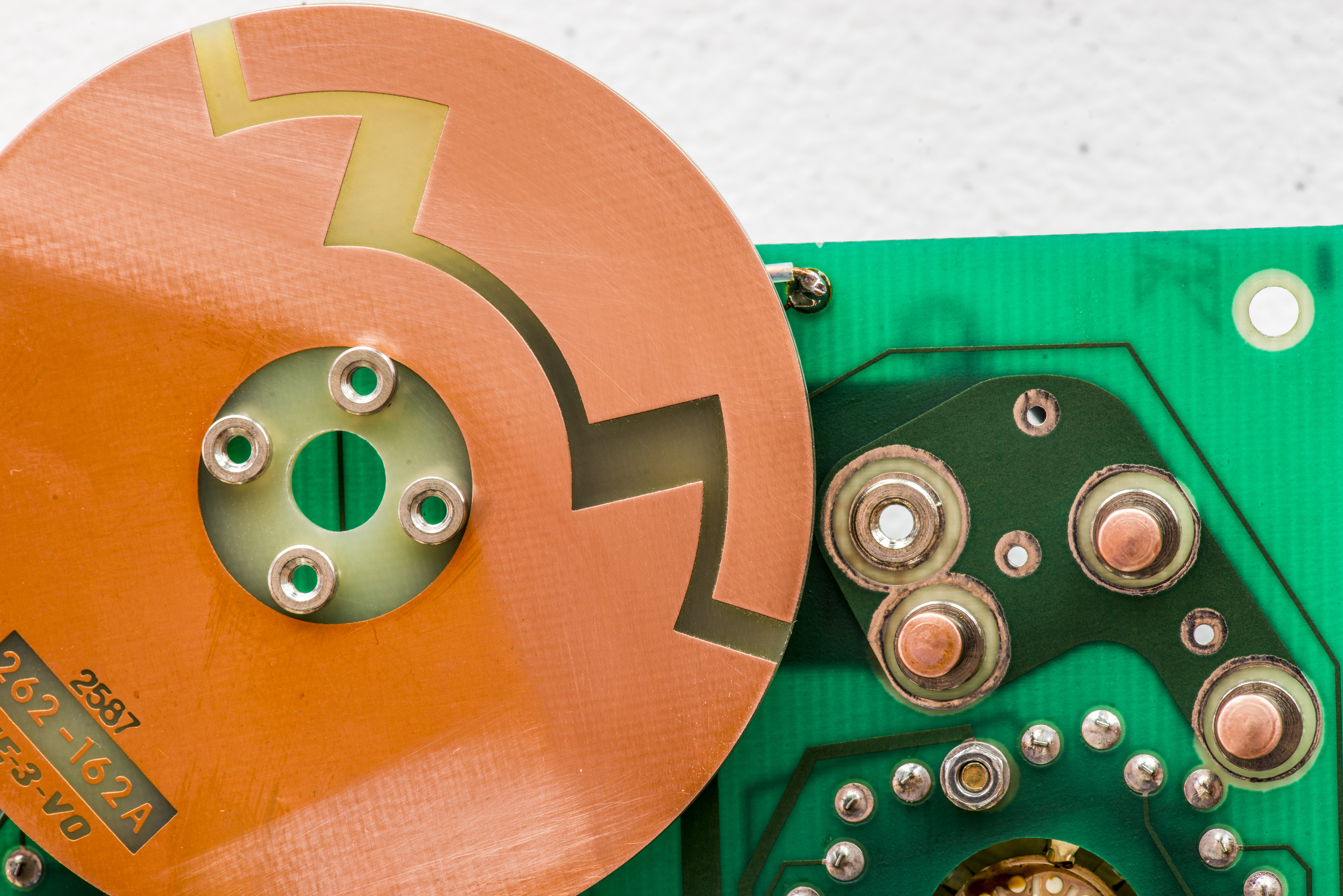
Image 13: After cleaning condition
Now unit ready for assembly and tests.
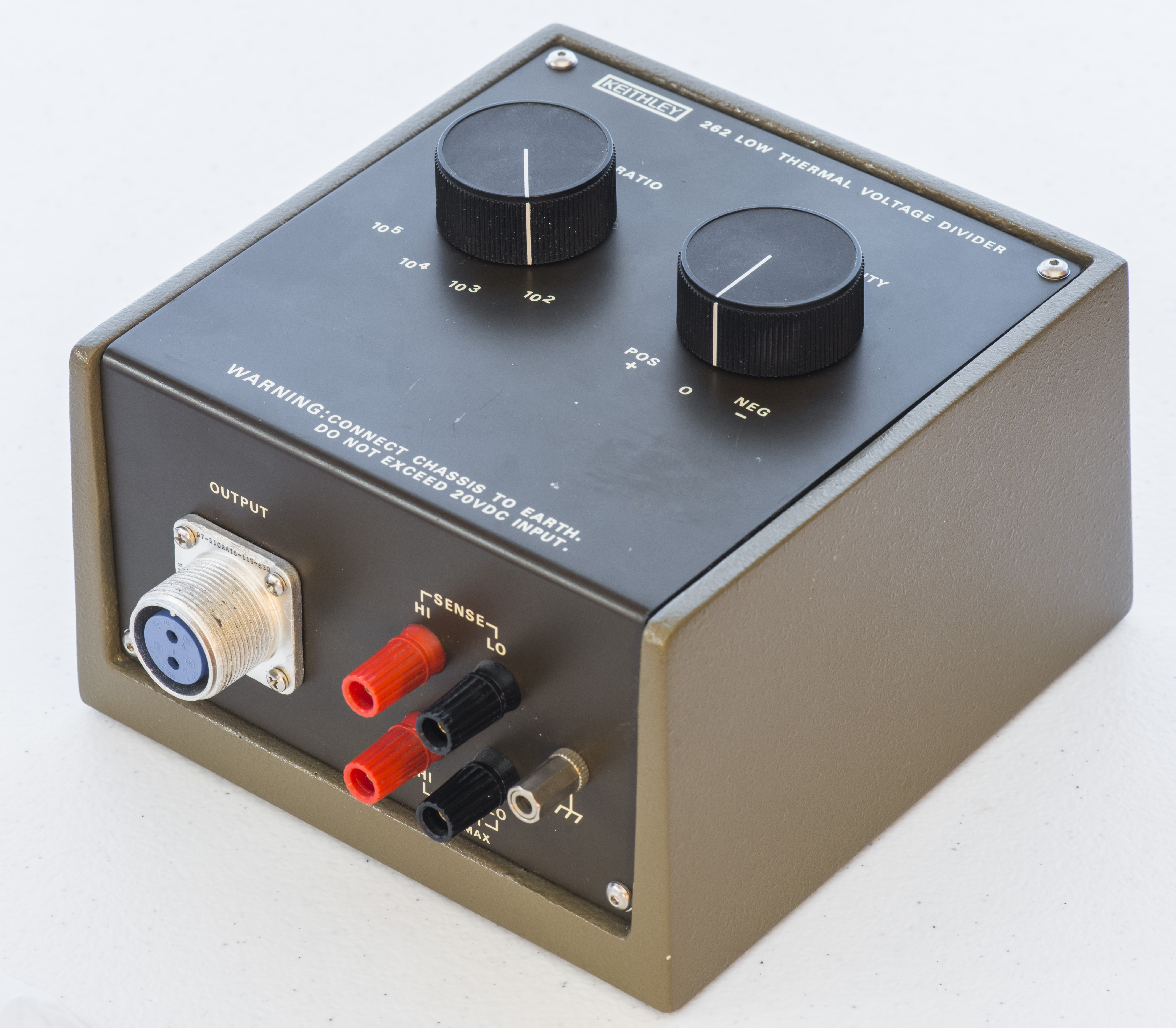
Image 14: Final assembled view
After service divider output was checked with HP 34420A and was indeed working. Contact resistance was bit unstable at first few times, so good amount of care still required using this divider.
Welcome to leave your commends and feedback, if you interesting to see more on use of this Model 262 divider in future experiments.
Projects like this are born from passion and a desire to share how things work. Education is the foundation of a healthy society - especially important in today's volatile world. xDevs began as a personal project notepad in Kherson, Ukraine back in 2008 and has grown with support of passionate readers just like you. There are no (and never will be) any ads, sponsors or shareholders behind xDevs.com, just a commitment to inspire and help learning. If you are in a position to help others like us, please consider supporting xDevs.com’s home-country Ukraine in its defense of freedom to speak, freedom to live in peace and freedom to choose their way. You can use official site to support Ukraine – United24 or Help99. Every cent counts.
Modified: Sept. 1, 2016, 11:45 a.m.