Intro
Precision bench-top multimeters from Keithley we already studied and even repaired before, which was covered in Model 2001 article and Model 2002 article. But it’s first time we have chance to meet rare Model 2001M, which was not shown before anywhere on web.
Index “M” likely comes from M*ilitary-version, which is hinted by extended documentation kit, and remarks about calibration in USA Navy documents, for example on FBO.gov website. Of course, I could be wrong, and that stands just for ([*M]odified), as it’s is adapted to modern components for production purposes. Not a secret that Keithley’s 200х series instruments were developed over two decades ago, and some of components used in their design are long time obsolete. There are semiconductor enterprises that did not last so long, as these meters do!
Exterior, construction
This model looks completely identical to usual 2001, all buttons, interface, labels are same. For those who did not work with Keithley 200x series gear, these instruments are bench-top type with possible rack-mount installation into standard 19” rack. Their dimensions are 2U height, and half-width, so two units can be installed into single 2U-height space.
Rear panel also shows no difference. Serial number of meter is 1411110, starts with one, similar to ours Model 2002 (which was manufactured in 2007). This already gives us a hint that instrument was manufactured not long time ago, which we will be able to determine more accurately by looking to components date codes.
So, let’s tear it apart and take a look what it have inside.
2001-M retail package
It’s worth a look on complete documentation package, which comes with 2001M:
PDF-versions of all documents are available for download:
Model 2001 Multimeter and Model 2002 Datasheet
Model 2001 Multimeter, Specifications, Rev.H, Feb 2009
Model 2001 Multimeter, Quick Reference Guide, Rev.B
Model 2001 Multimeter, Operator’s Manual, Rev.K, Aug 2010
Model 2001M Multimeter, Operator’s Manual, Rev.K, Mar 2011
Model 2001 Multimeter, Calibration Manual, Rev.G, May 2004
Model 2001M Multimeter, Calibration Manual, Rev.H, Mar 2011
Model 2001M Multimeter, Average RMS B16 Firmware Upgrade for Model 2001-M Release Notes
Model 2001 Multimeter, Model 2001-SCAN Scanner Card Instruction Manual, Rev.C, Jun 1998
Model 2001 Multimeter, Model 2001-TCSCAN Scanner Card Instruction Manual, Rev.B, Jan 1997
Model 2001 Multimeter, Scanner Option 2001-SCAN Specifications, Rev.B
Model 2001 Multimeter and Model 7001 / 7002 Switch System, software
Model 2001 Multimeter, Repair Manual, Rev.B, Feb 1996
Model 2001 Multimeter, Repair Manual, Rev.C, May 2011
Model 2001 Multimeter, Repair Manual Addendum, Rev.C, Mar 2011, BOM
Model 2001 Multimeter, Repair Manual Addendum Schematics part 1, Rev.C, Mar 2011
Model 2001 Multimeter, Repair Manual Addendum Schematics part 2, Rev.C, Mar 2011
There is also copy of bundled CD-ROM disk, zipped archive:
Model 2001M Operator’s Manual, Repair Manuals and catalog CD – 89 MBytes
User interface difference
Main menu and all functions are same, except one single difference: extra mode for ACV measurement – RMS-AVG. This mode is absent on usual Model 2001 version firmwares.
I did few photos to compare menu configuration for ACV function. On the right – DMM with firmware version 2001 A08, on the left – 2001M B17
As you can see, there is extra mode for RMS average (RMS-AVG). There is specific note for Firmware Upgrade for Model 2001-M Release Notes: Average responding RMS covering some details of this function.
Operation
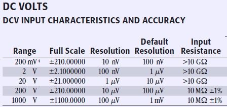
In DCV mode 2001M DMM, just like most of others benchtop multimeters, have high input impedance on 20V and lower ranges:

That’s why if input terminals are floating and not connected to signal meter will read some random charge values. That’s is completely normal and not a reason to alarm user, as it’s just picking up static electricity around and charging up small but existing capacitance on input networks of meter itself. This is typical behavior of high-impedance circuits and most of high-end multimeters have this behavior.
To confirm that everything works just fine, you can apply signal or connect 10Meg resistor to input and should see correct stable reading. Model 2001 also have ability to switch between front or rear terminals, so pay attention to correct input location before you do your measurements.
Firmware dumps
| Firmware version | Combined binary | ODD ROM | EVEN ROM |
|---|---|---|---|
| Model 2001 A05 | 2001-A05 ROM binary LEND | ||
| Model 2001 A06 | 2001-A06 ROM binary LEND | ||
| Model 2001 A08 (Latest for A-verison, 4Mbit) | 2001-A08 ROM binary LEND | ||
| Model 2001 B06 | 2001-B06 LEND | 2001-803-B06 | 2001-804-B06 |
| Model 2001 B07, Version 13.1, Feb 4 10:18:36 EST 1994 | 2001-B07 LEND | 2001-803-B07 | 2001-804-B07 |
| Model 2001 B08, Version 17.1, Sep 6 16:12:29 EDT 1994 | 2001-B08 ROM Binary 2001-B08 LEND | 2001-803-B08 | 2001-804-B08 |
| Model 2001 B09, Version 23.1, Jun 12 12:17:07 EDT 1995 | 2001-B09 LEND | 2001-803-B09 | 2001-804-B09 |
| Model 2001 B10, Version 29.1, Feb 5 09:56:39 EST 1996 | 2001-B10 ROM Binary 2001-B10 LEND | 2001-803-B10 | 2001-804-B10 |
| Model 2001 B11, Version 35.1, May 6 15:15:32 EDT 1998 | 2001-B11 LEND | 2001-803-B11 | 2001-804-B11 |
| Model 2001 B13, Version 45.1, Apr 29 13:10:54 EDT 1999 | 2001-B13 LEND | 2001-803-B13 | 2001-804-B13 |
| Model 2001 B15, Version 54.1, Oct 23 08:57:18 EDT 2000 | 2001-B15 ROM Binary 2001-B15 LEND | 2001-803-B15 | 2001-804-B15 |
| Model 2001M B17, Version 7.1, Nov 5 08:32:34 EST 2009 | 2001M-B17 LEND | 2001M-803-B17 | 2001M-804-B17 |
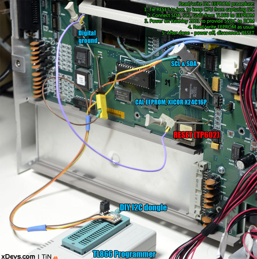
There is easy way to read and backup calibration ROM as well, using external programmer, such as TL866. Procedure and connections shown on photograph below.
To read firmwares we used I2C programmer and held CPU RESET signal low during programmer readout (TP602 shorted to DGND):

It’s wise to backup calibration ROM before attempting own recalibration or sending unit to service, just in case.
Calibration EEPROM dump (chip U634):
Model 2001-M Calibration EEPROM dump
For those who want upgrade their 2001 to 2001M, I tried to flash usual Model 2001 with digital board revision K (two ROM chips) with this firmware 2001M B17, and everything went well. Meter was detected as 2001M and all functions were operation correctly. No recalibration was required.
If you have another Keithley Model 2001M firmware’s (or any other Keithley instrument firmware), please upload here.
Internal construction
After cover removal, we can see analog board with all magic on it. Everything is very similar to old Model 2001 units, except few details, which we cover later here.
Analog board version: 2001-102-01R, Revision R
Digital board: 2001-142-06K, Revision К (exactly same as used in old Model 2001 from 1994, and Model 2002)
Quick look on analog board:
Input voltage selection circuitry and earth-referenced supply is identical to old revisions. Bootstrap supply with capacitors C114-117 also did not had any change, compared to old units. Electrolytic capacitors are made by Nichicon, series VZ, design to operate with temperatures up to +105°С. That is very needed, as caps located just next to hot linear regulators and transformer.
AC measurement block is based around TrueRMS function of Analog AD637JR, which is completely repeated after original design and used in 2001М without changes, as well as in 8½-digit 2002.
Film capacitors C557,C553 are now SMD-type. PCB location for wired version also retained on both, so either type is possible.
Instead of optocouplers TLP582 found in old meters, this one have little board with model number 2001-152A and pair of 110 Mbps 4-channel isolation ICs NVE IL717. Similar module we already saw in Model 2002 multimeter, with different number 2002-132-01A (shown on right photo)
Reed relays are manufactured by American Relays, except K300.
К300 relay now replaced to shielded reed relay from Taiwanese company IC-HI Technology Co.,Ltd.. Relay model is TPM 108D-1A11N2-61. Interesting to note, that their location is within 5 minute walk from our xDevs.com lab.
Resistor divider R607 (9.9 MOhm / 100 KOhm) is now built using pair of alumina-based precision stable CADDOCK resistors, TF050R TF-255 and TF020R, glued together to equalize temperature of divider. This helps to improve ratio stability and tracking of such divider, and reduce errors from temperature variations.
Ohms current sources and range switching circuitry did not change as well, same old Vishay foil resistors.
There are few extra parts, such as transistors Q550, Q552 next to guard circuit driver U331.
Main +6.95V VREF is our old friend, selected LM399. This chip have internal heater and thermostat circuit, so it enjoys very low tempco and excellent long-term stability, which is crucial for such high-end multimeter.
Additional analog board photos:
Let’s take a look on digital board.
This board already familiar, as we reviewed this platform before in Model 2001 and Model 2002.
ADC board module marked as 2001-162N, Revision N
This multimeter using fresh new ADC module, with modern TQFP-packaged CPLD or FPGA from ACTEL. If anyone have idea which model that chip is – please let us know.
Front panel board and keyboard
Final test and check
Hope you enjoy this prompt review and all suggestions are welcome in comments
Projects like this are born from passion and a desire to share how things work. Education is the foundation of a healthy society - especially important in today's volatile world. xDevs began as a personal project notepad in Kherson, Ukraine back in 2008 and has grown with support of passionate readers just like you. There are no (and never will be) any ads, sponsors or shareholders behind xDevs.com, just a commitment to inspire and help learning. If you are in a position to help others like us, please consider supporting xDevs.com’s home-country Ukraine in its defense of freedom to speak, freedom to live in peace and freedom to choose their way. You can use official site to support Ukraine – United24 or Help99. Every cent counts.
Modified: Feb. 14, 2016, 12:40 p.m.


