If you follow the discussions on EEVBlog metrology section you may have come across the thread Wavetek 7000, the hidden gemstone. Member chekhov provided a reverse engineered schematics of the Wavetek 7000 voltage standard to the open community. This schematics is showing the complete circuit together with trim configurations and output stage.
Disclaimer
Redistribution and use of this article, any part of it or any images or files referenced in it, in source and binary forms, with or without modification, are permitted provided that the following conditions are met:
- Redistributions of article must retain the above copyright notice, this list of conditions, link to this page (https://xdevs.com/article/b7000/) and the following disclaimer.
- Redistributions of files in binary form must reproduce the above copyright notice, this list of conditions, link to this page (https://xdevs.com/article/b7000/), and the following disclaimer in the documentation and/or other materials provided with the distribution, for example Readme file.
All information posted here is hosted just for education purposes and provided AS IS. In no event shall the author, xDevs.com site, or any other 3rd party be liable for any special, direct, indirect, or consequential damages or any damages whatsoever resulting from loss of use, data or profits, whether in an action of contract, negligence or other tortuous action, arising out of or in connection with the use or performance of information published here.
If you willing to contribute or add your experience regarding instrument repairs or provide extra information, you can do so following these simple instructions.
Alternative LTZ1000-based design concept details
But what’s so special about that particular voltage standard?
It is based on an ovenized LTZ1000CH zener with a slightly different circuit implementation compared to the typical LTZ1000 datasheet. Furthermore, it uses a special conditioning circuit driving the heater of the zener diode to recover the output voltage after a power down. It makes elaborate use of integrated resistor networks for setting the oven temperature and voltage scaling to the 10 V and 1 V/1.018 V output levels [9] , [10] , [4].
And finally, Model 7000 uses a high-isolation, low leakage current DC-DC converter to power the unit from a linear wall adapter [3] , [5], [1]. In the Wavetek 7000 and early units of Fluke-branded Model 7000 the driving transformer circuit was built with discrete circuit, while in later Fluke-branded version of 7000 references the driver is based on integrated solution around Linear Technologies (now ADI) LT1533 ultralow noise 1A Switching Regulator IC.
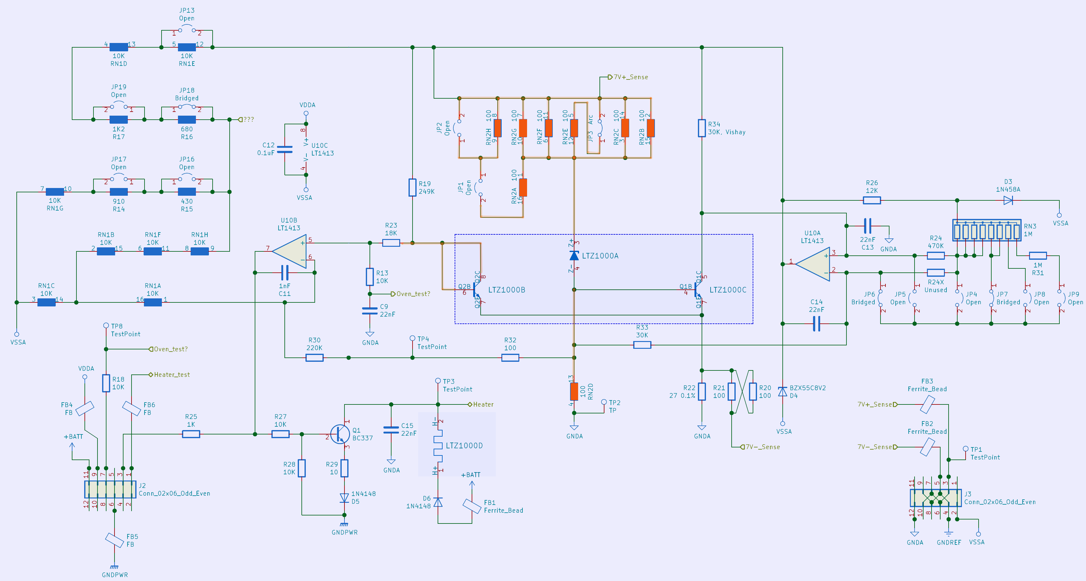
Figure 1: Recovered reference schematic section of Wavetek/Fluke 7000 .
Looking at the basic reference part in the mentioned schematics provided for the Wavetek 7000 (see figure 1), what first comes to the eye is it uses the temperature sensing transistor as a diode (LTZ1000B transistor). Second, a small resistor at the cathode is added (orange).
Both of these differences to the standard datasheet schematic can also be found in [8] , while the datasheet explains that such a resistor at the cathode can be used to reduce the temperature coefficient (TC) of the unheated zener [9] . This is achieved by shifting the parabolic TC curve along the temperature axis.
However, there is still only a specific temperature at which the temperature coefficient is zero and small next to it on the left and on the right side. That means, if the TC of the unheated zener is reduced from ~50 ppm/°C to a much lower value also the requirements of the oven temperature setting resistors are decreased.
In the 7000 voltage standard an 8 × 100 Ω resistor network TDP16031000 is used to create an adjustable resistor at the cathode with the following values (see table 1) by setting corresponding solder links in the 7 resistor arrangement, while the 8th resistor is used between anode and ground.
| SL1 | SL2 | SL3 | SL4 | |
| 33.333 Ω | ||||
| 28.571 Ω | X | |||
| 25.000 Ω | X | |||
| 25.000 Ω | X | |||
| 25.000 Ω | X | |||
| 22.222 Ω | X | X | ||
| 22.222 Ω | X | X | ||
| 20.000 Ω | X | X | ||
| 20.000 Ω | X | X | ||
| 20.000 Ω | X | X | ||
| 18.182 Ω | X | X | X | |
| 16.667 Ω | X | X | X |
Table 1: Resistor trim settings with the solder links map
This allows to shift the zero TC temperature into a range where the TC is low or even zero at a 50 °C oven temperature. This temperature in fact is small, but still leaves enough headroom for higher ambient temperatures. On the other hand, one wants to operate the oven at low temperatures to save energy, but also to decrease long-term drift of the reference, as per Arrhenius equation the long-term drift about halves to quarters with every 10 K temperature reduction.
Now that the zener is operated near to or at zero TC temperature, a 10 kΩ resistor network with reduced requirements, here a TDP16031002, is used to set the oven temperature (solid blue). The TDP1603 resistor series has a specified absolute TCR of ±25 ppm/°C, while the tracking TCR of 8 resistors is specified to be ±5 ppm/°C, but often performs much better in reality.
The benefit of a low requirement for the oven temperature set point resistors combined with a resistor network with low tracking TCR eliminates the demand for high quality, high stability, low TCR hermetically sealed resistors. Compared to the datasheet circuit with the typical R4 = 13 kΩ and R5 = 1 kΩ for the temperature set point, a 100 ppm change of the resistor ratio leads to a 1 ppm change of the zener voltage, since the reference is operated on the rising slope of the TC curve. When it comes down to noise all of the resistor networks mentioned in this article are performing superior as pointed out by [8] .
Third, the heater is in the collector instead of the emitter node. This allows to turn on and off the heater. And finally, it uses a small trick to adjust the residual TC to almost zero, which will be kept a secret, while it is up to the intent reader to find out how.
With these basics in mind a simplified version of this zener reference circuit was designed, which means that the conditioning part was ignored and the reference has a fixed 10 V boost stage. It makes use of resistor networks and instead of adjusting the output voltage by a DAC it trims individual resistors of the network in the 10 V boost stage.
It follows the approach that you would do with any other temperature compensated zener reference, that is: Adjust the zener current so that the zero TC is at or at least close to the temperature you want to operate the oven at, only slightly above the maximum room temperature, but with enough headroom for the temperature regulation to eventually save energy and to allow for long battery operation. For the 100 Ω resistor network a TOMC1603 was used, as it was the only network with low noise and 100 Ω resistors in one package available at that time. For the temperature set point divider a TDP16031002 resistor network was used, but a TOMC16031002 or NOMC16031002 would have worked too.
For the ease of routing the board 2 x LT1006 where used instead of original 1 x LT1013 or the more modern LT1413. Finally, the output stage uses a chopper Analog Devices ADA4522-1 and a filter at its input with another trimmable TDP16031002 resistor network to adjust the final gain to roughly 1.4.
Figure 2 shows an image of the assembled board missing only the 10 V boost stage.

Figure 2: Preassembled reference board
First temperature profiles were measured with the internal LTZ heater turned off to find the proper resistor value at the cathode. Therefore, the solder links were set accordingly.
As can be seen in figure 3 a resistor value of 18.18 Ω worked best for this particular LTZ1000CH zener with the zero TC temperature point found at 48 °C, which corresponds to a voltage of 0.54 V at the temperature diode sensor. A resistor value of 20 Ω shifted the zero TC temperature to lower and a resistor value of 16.667 Ω to higher temperatures. The diagrams are in ppm scale with respect to the output voltage at 23 °C.
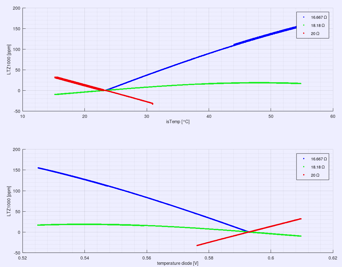
Figure 3: TC of the zener voltage for different resistor values in the cathode
Next the LTZ1000 heater was turned on and the temperature set point resistor network trimmed so that a voltage of 0.54 VDC at the temperature diode was present. This was done by using a decade resistor box parallel to corresponding elements of the resistors network and replacing it later by a proper fixed value resistor with 10 ppm/°C. Another temperature profile was run to find the residual TC of the circuit. As it turned out a positive TC of 0.175 ppm/°C was observed (see figure 4), that was compensated and thus reduced to -0.0106 ppm/°C afterwards (see figure 5), not by using a dubious 400 kΩ resistor as mentioned in the LTZ datasheet, but by the aforementioned secret.
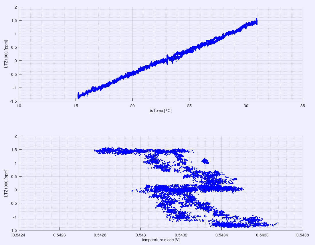
Figure 4: residual TC of the zener voltage with the heater turned on
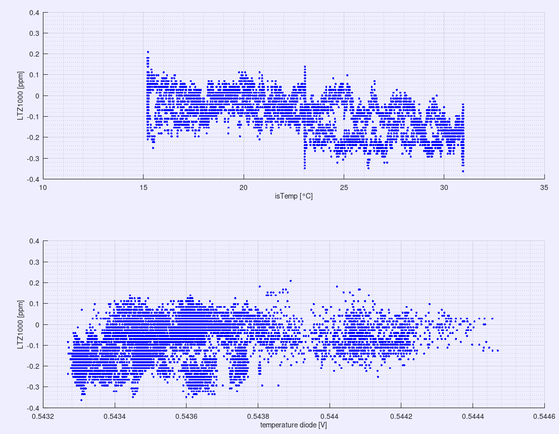
Figure 5: residual TC of the zener voltage after TC compensation.
Next the amplifier stage was populated to get the zener voltage to 10 VDC. This stage again needed TC trimming, but also trimming of the output voltage itself, which influence each other.
In figure 6 the output voltage of this simplified LTZ1000CH DC reference is compared over temperature change to a Fluke 7000 voltage standard sitting at room temperature during the measurement.
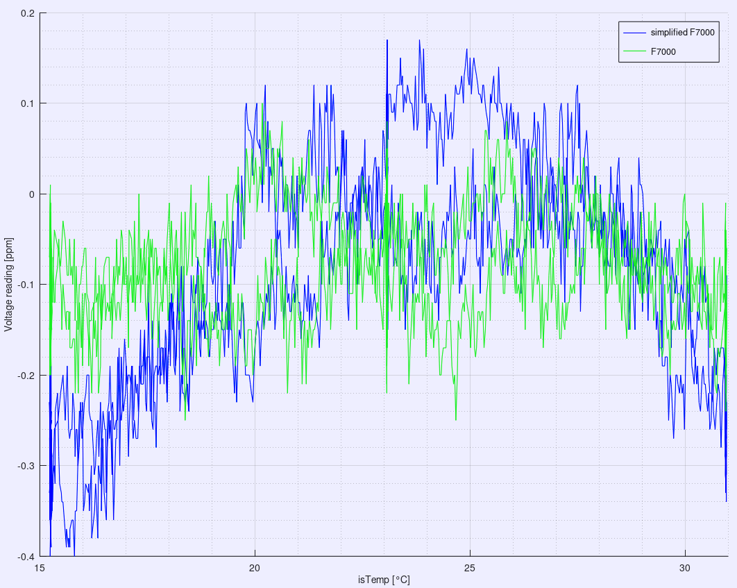
Figure 6: Residual TC(temperature coefficient) of the 10 V output voltage
Unfortunately, the TDP16031002 resistor network and mainly the output voltage trimming within it by parallel resistors to individual elements, added a small portion of non-linear TC. The final result that has been reached is an output voltage of what is believed to be 10.0000054 V right after ACAL of the meter – average over 100 samples – with a linear TC of +0.0138 ppm/°C, but containing a nonlinear component.
Summary and conclusion
Since the Fluke 7000 and it simplified version are tracking each other (see figure 7) the changes in output voltages are mostly due to the stability and TC of the DVM used.
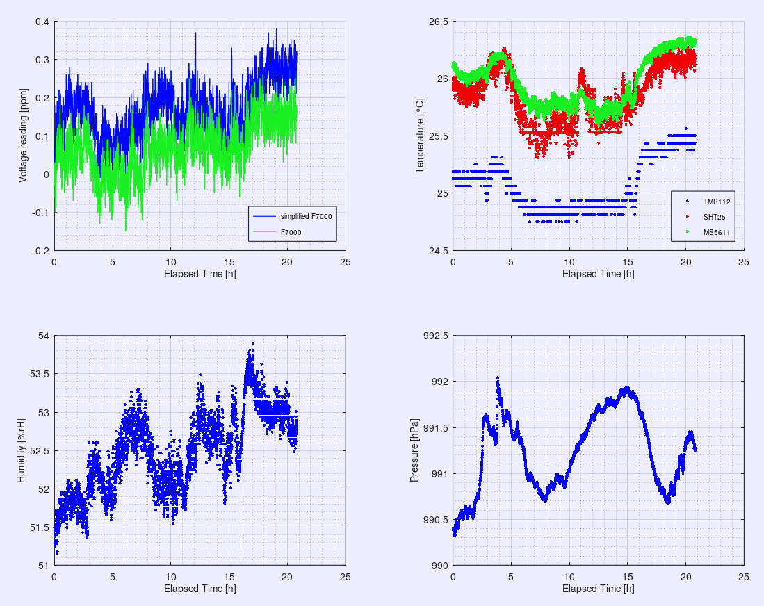
Figure 7: 21 h stability measurement of the simplified Fluke 7000 reference compared to an Fluke 7000 voltage standard
Stay tuned and let us know your feedback! Discussion about this article and related stuff is welcome in comment section or at our own IRC chat server: irc.xdevs.com (standard port 6667, channel: #xDevs.com). Web-interface for access mirrored on this page.
Projects like this are born from passion and a desire to share how things work. Education is the foundation of a healthy society - especially important in today's volatile world. xDevs began as a personal project notepad in Kherson, Ukraine back in 2008 and has grown with support of passionate readers just like you. There are no (and never will be) any ads, sponsors or shareholders behind xDevs.com, just a commitment to inspire and help learning. If you are in a position to help others like us, please consider supporting xDevs.com’s home-country Ukraine in its defense of freedom to speak, freedom to live in peace and freedom to choose their way. You can use official site to support Ukraine – United24 or Help99. Every cent counts.
Modified: March 13, 2022, 9:13 a.m.
References
- EEVBlog : Wavetek 7000 thread
- Pickering, J*; Thompson, R; Williams, J M (1999) A new compact isolated power supply for electrical metrology at low signal levels. In: BEMC 99 - 9th International Conference on Electromagnetic Measurement, 2-4 November 1999, Brighton, UK.
- US005369245A, „Method and Apparatus For Conditioning An Electronic Component Having A Characteristic Subject To Variation With Temperature“, John R. Pickering, Metron Designs Ltd., 1992
- WO97/21233, High isolation power transformer, John Robert Pickering, Metron Designs Ltd. 1996
- Gunnar Fernqvist et al., „Design and Evaluation of a 10-mA DC Current Reference Standard“, IEEE TIM, April 2003
- Andriy Marusenkov, "Possibilities of further improvement of 1 s fluxgate variometers", Geoscientific Instrumentation Methods and Data Systems, 2017
- LTZ1000/LTZ1000A Ultra Precision Reference datasheet, „Adjusting Temperature Coefficient in Unstabilized Applications“, page 6
- Nikolai Beev, "Measurement of Excess Noise in Thin Film and Metal Foil Resistor Networks", 2021
- Peter B. Crisp, "Setting New Standards for DC Voltage Maintenance Systems", Wavetek Ltd., CalLab, Sep./Oct. 1999
- John R. Pickering, "Setting new standards for DC Voltage Maintenance Systems", Metron Designs for Wavetek Ltd, UK