Intro
For some time now I’ve been meaning to play around with voltage references, tempco characterization and basically just doing some good old fashioned ppm-wrangling. Why, you ask? Well, it’s fun, I get to make this into an excuse to buy more gear and most important, it’s a fantastic learning experience. DC to 100 Hz is just a fraught with snags and traps as 1 GHz to daylight.
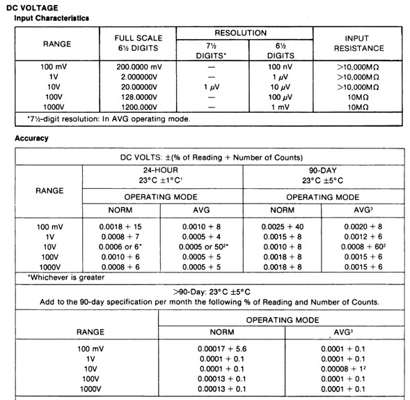
So, after looking around for a DMM that doesn’t break the bank and also has decent performance, I stumbled upon Fluke’s old 8505A DMM. Looking at the specs, for something straight from the 80’s, it looked pretty decent: 6.5 digits, proper binding posts, but what really drew me in was the fact that the meter will also do 7.5 digits on the 10V range, with averaging. Winner winner chicken dinner!
6 ppm accuracy on the 10 V range, 5ppm with averaging. Not bad at all for something this old. As a stepping stone into this area of electronics, it’s a great piece of gear. Also, as a side-note, the voltage reference of the DMM is the famous SZA263, so if you do some calibration cycles to gain confidence in your readings, I think it can go to much lower accuracies than the stated ones. I’m still getting to learn about mine and making my own voltage references, so it’ll be some time before I can definitely confirm this.
And after digging around on the bay, I snagged a cheap-ish 8505A. Yeey!
Disclaimer
Redistribution and use of this article or any images or files referenced in it, in source and binary forms, with or without modification, are permitted provided that the following conditions are met:
- Redistributions of article must retain the above copyright notice, this list of conditions, link to this page (https://xdevs.com/article/f8505a/) and the following disclaimer.
- Redistributions of files in binary form must reproduce the above copyright notice, this list of conditions, link to this page (https://xdevs.com/article/f8505a/), and the following disclaimer in the documentation and/or other materials provided with the distribution, for example Readme file.
All information posted here is hosted just for education purposes and provided AS IS. In no event shall the author, xDevs.com site, or Fluke or any other 3rd party be liable for any special, direct, indirect, or consequential damages or any damages whatsoever resulting from loss of use, data or profits, whether in an action of contract, negligence or other tortuous action, arising out of or in connection with the use or performance of information published here.
If you willing to contribute or have interesting documentation to share regarding pressure measurements or metrology and electronics in general, you can do so by following these simple instructions.
Manuals
Fluke 8505A and 8506A Spec Sheet
Unboxing therapy
The front panel looks to be in nice shape:
When the meter arrived, I was really surprised when looking inside. According to label on the back, it’s fitted with the Ohms converter, Current Shunt and GPIB options but it was a nice surprise to also see the AC RMS converter in there. What can I say, sometimes even I get lucky.
And hey, look at that, it even works. Oh, also, if you buy one of these, don’t forget to switch it to 220 / 230 V AC
On the back there’s a weird looking connector for the rear connections and also something on there that might be really useful: and External Reference Input. Cool. Also, there’s a Guard for the Ohms measurement that the front panel does not have.
The 8505A and it’s Thermal AC measuring cousin, the 8506A were marketed as a performance DMMs, with the 8505 being “Fluke’s lowest cost DMM having top DC accuracy”. And the “lowest cost” can really be seen on the inside, once you take out a module and look at how they designed and layed it out. But giving credit where credit is due, they did some interesting and clever things to cut costs and still get adequate performance out of the thing, so kudos to them.
Initial power-up
So, what did I get for my money? Well, the default measurement set-up of the DMM is to measure DC voltages. Everything else comes as an option. As I’ve mentioned, I was really lucky with this DMM to have Ohms, Amps, AC RMS and GPIB modules on it. The DC Volts seems to be OK and all that it needs is a proper calibration. The Ohms module also is OK, but it’s in need of some serious calibration on all ranges. So far so good.
However, things are a bit different when selecting V AC. This displays an “Error 9”, which basically means that something is wrong with the RMS converter module. Guess I’ll have to fix that. And the last one is the Amps module. It’s especially nice because it can do AC measurement or AC plus DC measurements. But this is something a bit further down the line, as for right now, the displays shows “HHHHHHH” on all ranges. Definitely something’s also wrong with this one.
Ok, so because I’m going to have to get into the DMM anyway, let’s see how Fluke designed the modules in this thing.
Optional modules
My Fluke 8505A with the populated modules. And yes, the thing came with those pieces of kapton tape.
A/D Coverter
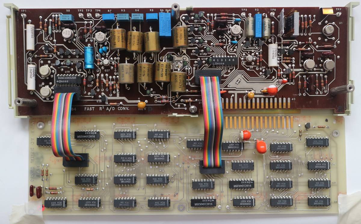
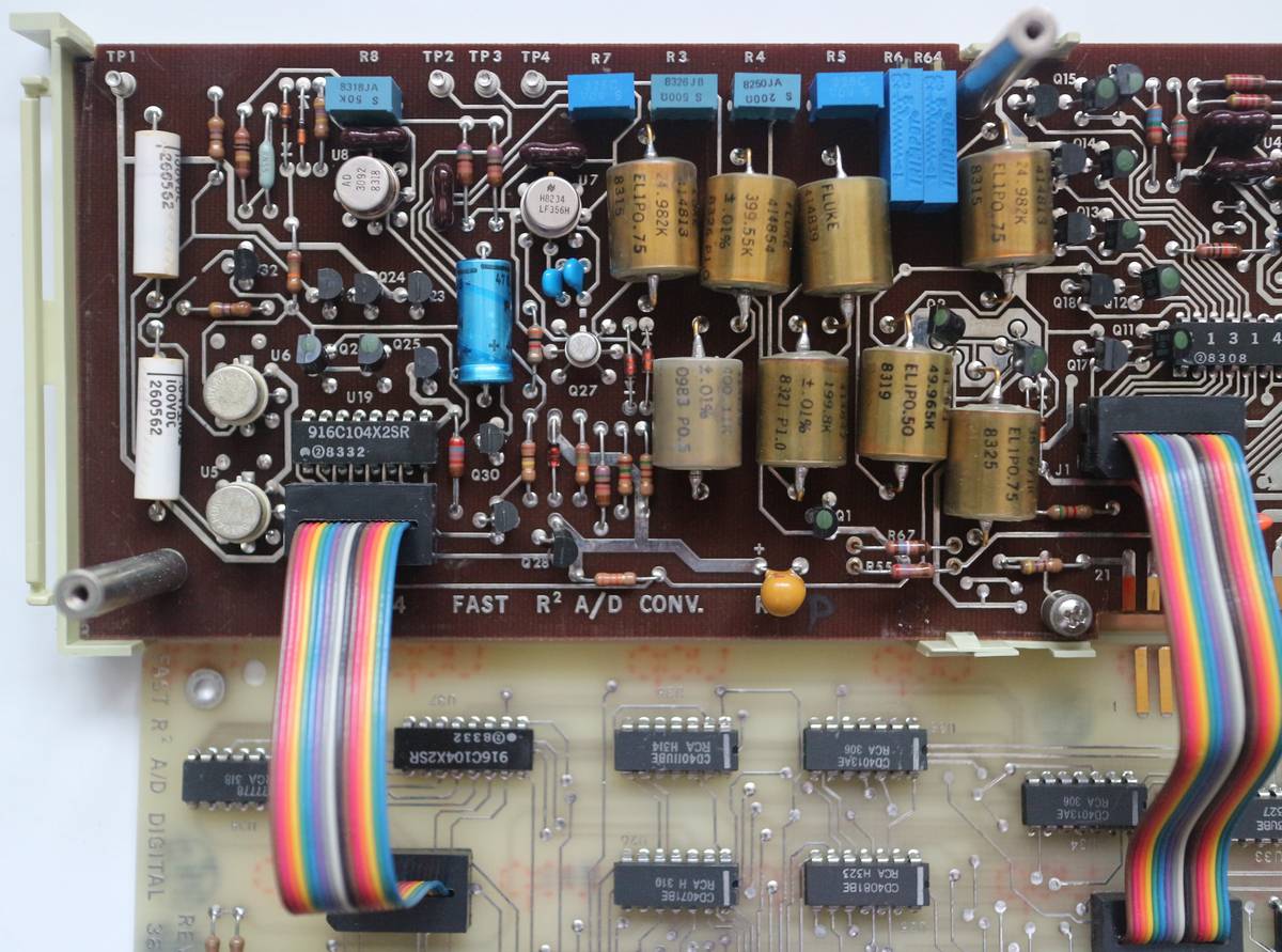
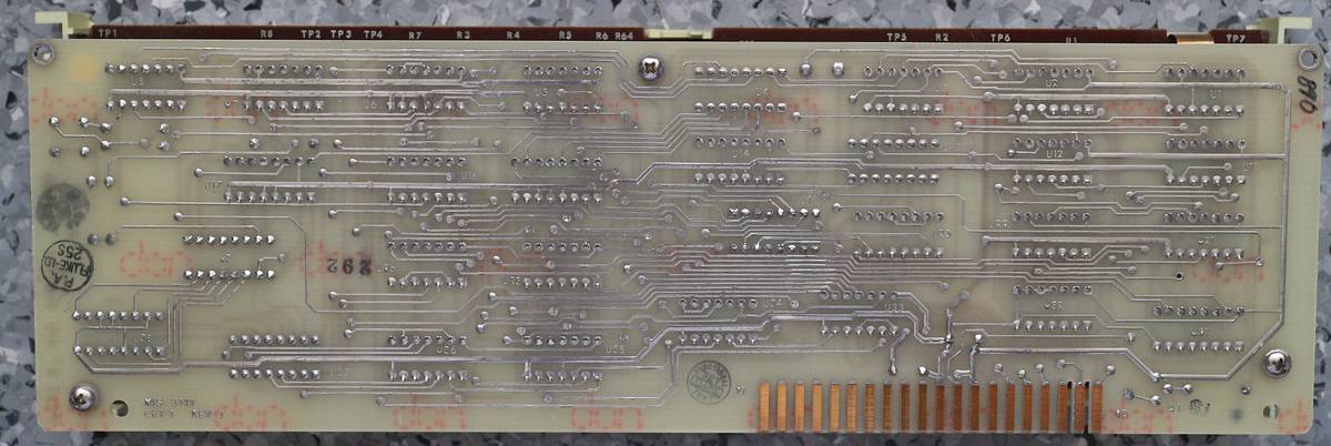
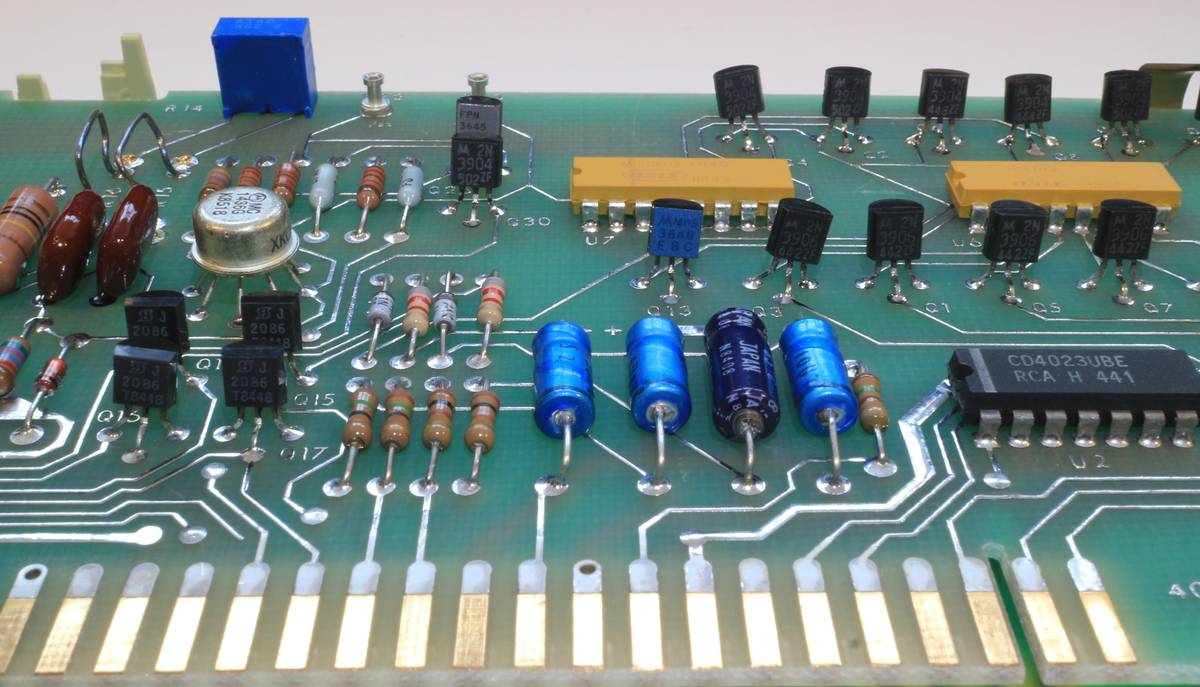
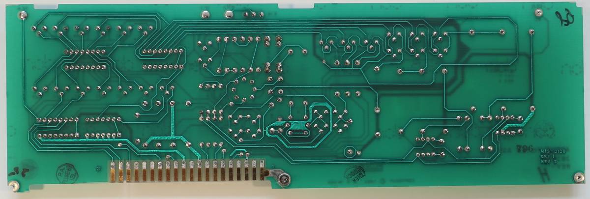
Heart of the meter – A/D Converter module, which consists of two boards. Digital board handles timing and control, mostly build using 4000 series logic ICs, while analog board have all the magic parts for integrating ADC.
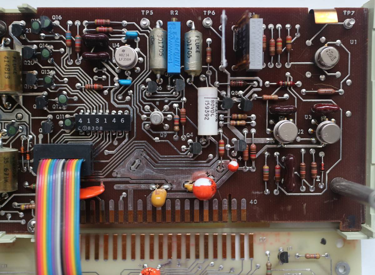
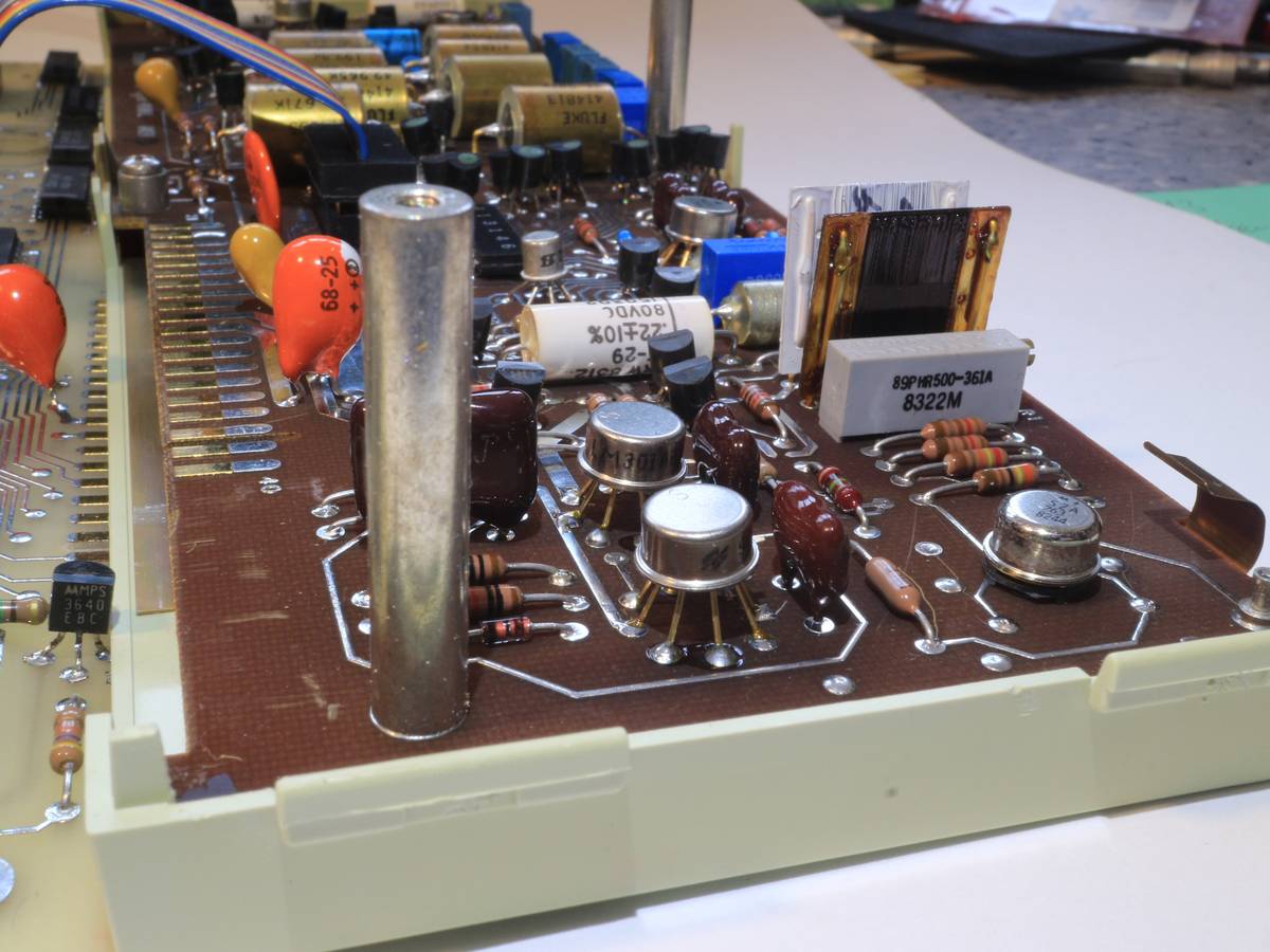
According to date codes, this ADC built in beginning of 1983, good 36 years ago. There is special Fluke ASIC with custom partnumber 413146. Let’s hope this unreplaceable chip is still good. Voltage reference is visible on this photo as well, metal can U1 sitting on the right top corner of the PCBA.
Stability and currents for each step are maintained by custom Fluke precision wirewound resistors in hermetic brass cans. They are also datecoded 1983, and have marking for tempco from +0.5 to +1.0 ppm/°C.
Better photo close up on Motorola SZA263, same as one used in legendary Fluke 732A DC references. Two wirewound resistors on mica sheet and precision trimpot are likely related to reference circuit as well.
Isolator and Trigger Module
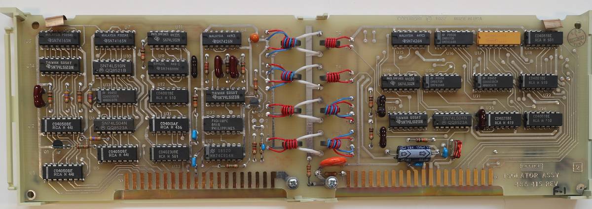
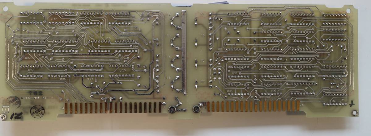
This board is filled with 7400 and 4000 series logic ICs and provides galvanic isolation between earth-referenced outguard and inguard floating analog sections of the DMM. Unlike most of modern instruments 8505A use electromagnetic coupling with discrete inductors and pick-up coils. Interesting solution.
DC Signal Conditioner
This board handle DC measurement functionality and has high-voltage attenuator network. Various ranges use set of precision hermetic Fluke resistors. This board has carbon composite R8 resistor and bunch of little tantalum caps, that should be inspected for failure. Two metal cans on left side are Analog Devices AD301AH parts.
Controller Module
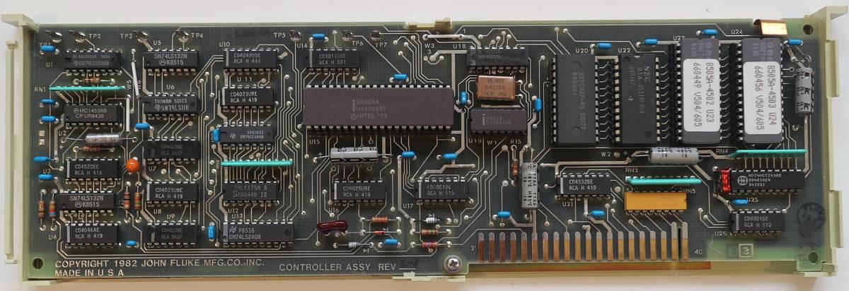
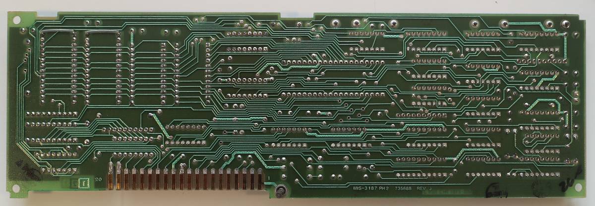
Main brains of the meter built around Intel 8080 processor. Firmware in this meter have version 504/605, stored in two UV EPROMs DO2764 with part numbers 8505A-4502 and 8505A-4503.
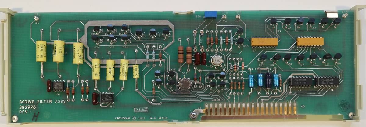
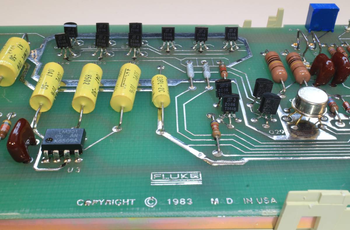
Active Filter
Ohms Converter
This module responsible for creating test currents for resistance functionality of 8505A.
It has very nice Fluke hermetic sealed precision resistors in traditional brass metal cans, typical for Fluke instruments in 90’s. High-impedance COTO 1240 reed relays and latching DS4E-ML2 route signals to different circuits. Many ICs are in hermetic TO-style can packages. Board also have programmable GAL26CV128 gate array, Fluke P/N 911441.
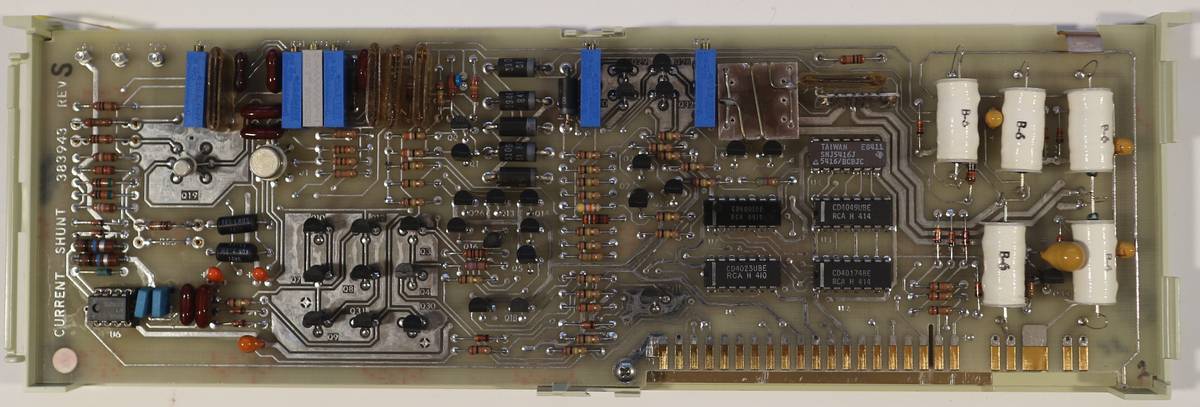
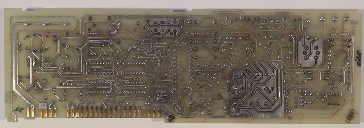
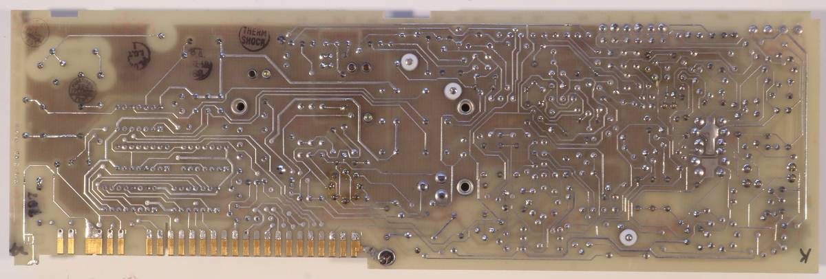
Current Shunts
This board use precision Fluke wire-wound resistors to convert input currents into voltages, that can be measured by ADC.
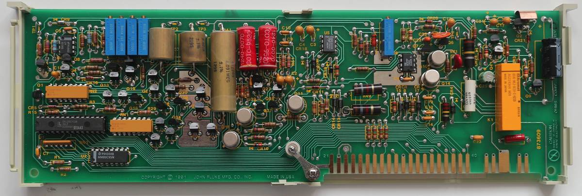
AC RMS Converter
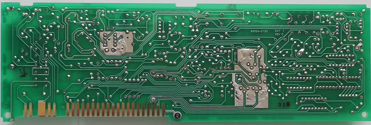
This module handles RMS conversion for AC measurements function.
Pretty and expensive variable capacitors located on top board edge used for frequency correction in various ranges. Reed relays used to switch circuit ranges and sections, while maintaining low capacitance and high isolation.
Repair
Well, time to get into the meat of’er.
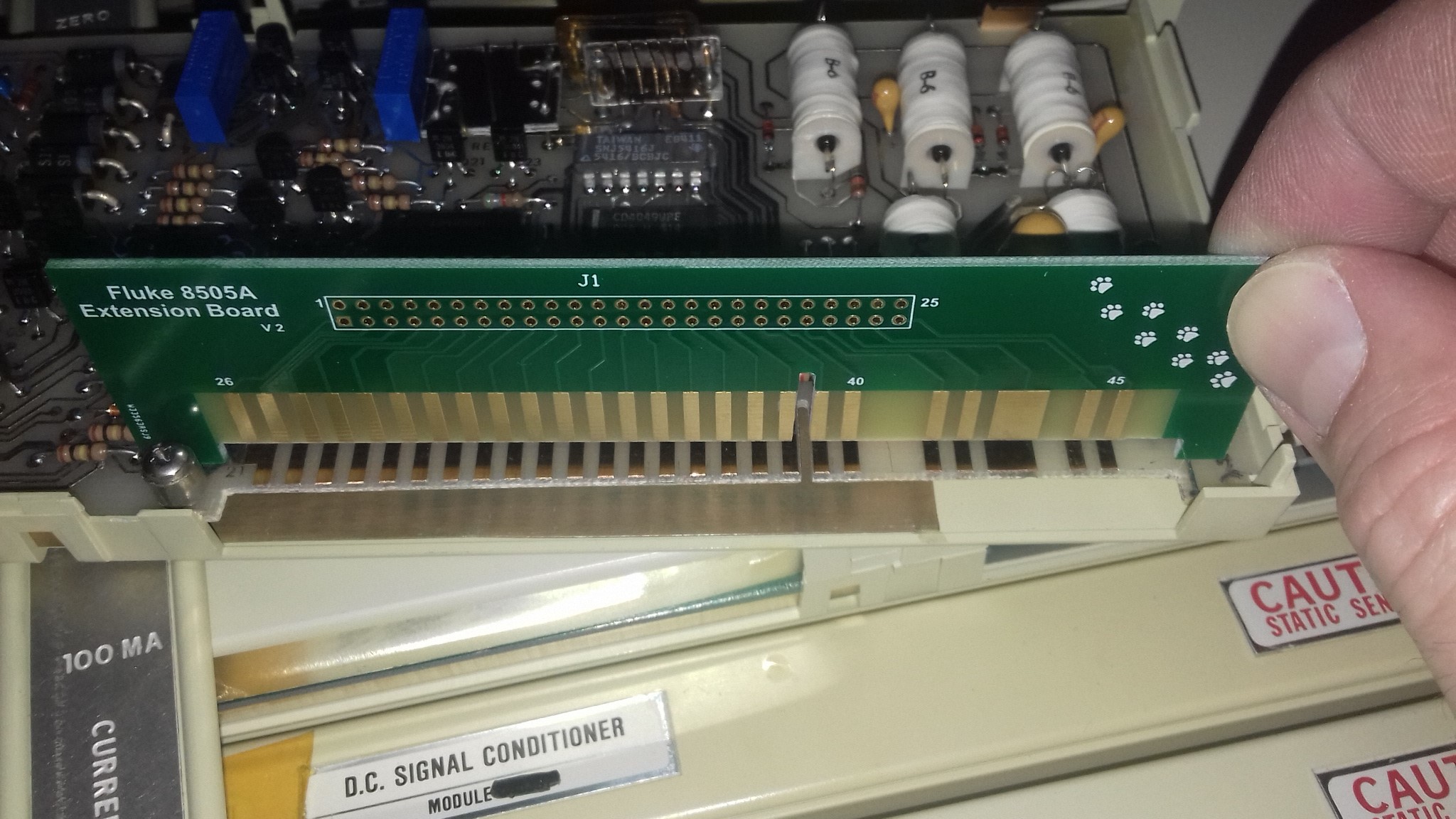
Heh, not so fast, cowboy… because we’re talking Fluke here, things aren’t that simple. First, There’s a matter of actually getting to the test points on a module while it’s powered up. So the only way to do this is to have some kind of extender card or cable. The interface to the DMM isn’t anything high-speed or pretentious, so just hooking up things with wires is good enough. No impedance controlled non-sense :)
But, and this is a big but, Fluke used an odd-ball pitch connector. It’ s 3.96 mm pitch instead of the regular and inexpensive 3.81 mm. Digikey, Mouser and all the other big names didn’t have something like that in stock, which was kind of a pain. And for that matter, neither did big manufacturers like AMP or Harting. Looking high and low for some connectors, (took me the best part of a day of continuous searching) I finally found something in the USA, New-Old Stock. 60 dollars including shipping, which was about half the price of the 8505A. Oh well… I had to buy 2 connectors and basically bodge them together to get the odd custom configuration that Fluke used. A bit of dremeling and some epoxy and aluminium bits later, we have this monstruasity of a connector:
Ah, but the fun’s not over yet. I also need a small PCB made that fits the even more odd-ball pin configuration that Fluke came up with. I did my best to measure everything with a calliper and in the end I got the pin positioning right in only two board versions.
And the connector all wired up:
NOW we can get to work on fixing this ancient beast.
Current Shunts Repair
First off is the Current Shunts. When turning on the meter, the meter displays all the installed modules. The Current Shunts is Option 3, and as one can see, it’s not detected.
Also, when trying to access the AC or DC Amps measurements, the display shows “Error 9”. Searching through the Service Manual, one can only find some general troubleshooting guide for this module and that’s about it. Apparently Error 9 and Error 4 can have the same common causes: U6, CR14 and CR15 may be leaky, U5 and Q18. From playing around with this instrument, this is my take on what this error represents: Error 9 is shown whenever a module is seen as “faulty” from start-up (DMM power-on tests) On start-up, the DMM will address every possible module and then see which ones respond back. In turn, when a module is addressed, depending on what it is, it does some internal checks before sending back a response to the DMM controller module to tell it that everything is OK. If for some reason, that test fails, or it does not send back a response in due time,the Controller will presume the module faulty. Error 9 is what you get in that instance.
However, if at some point a module becomes faulty during use, i.e. after the start-up check, the display will show “Error 4”. Now, I think it’s worth mentioning that initially, I had some issues with troubleshooting. And here’s why: when a module is initialized, i.e. is addressed by the DMM, as I mentioned before, it does some error checking then replies back if everything’s OK or not. If the self check passes, then the DMM registers the module and allows it to be used.
What my issue was, after hooking up a Logic Analyzer and selecting the module through the front panel, I was missing the first response from the module. Whenever I selected the module, there was no initial ACK signal. This, together with Fluke’s troubleshooting guide, led me to believe that it was the digital section at fault, most likely U5.
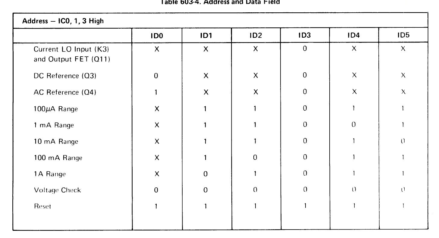
When the module is first addressed, the DMM sends all 1s on the data line, putting the module into a reset state. Then the Module would send it’s first ACK signal back, do the self-check then if this passes, send the second ACK to the DMM Controller. Now, I’ve read through the current shunts section to try to see how the initialization is actually done and basically try to get more details about the whole thing. The service manual was really loose on words and cheap on explanations, so much of what I’m writing here is based on personal observations and deductions.
Taking another approach, I tried turning the DMM off and on again, (yes, IT joke) then set my L.A. to trigger on a would-be ACK signal and waited for data to come in. Lowe and behold, there was actually an ACK signal sent back to the DMM to the module. Aha! So the mdule is actually deemed usable or not at power-up, not whenever it is accessed for use. Makes sense. But there was no second ACK signal after that. Double Aha! So now, my attention started shifting to the analog section, in particular, the overvoltage detector, U6.
As in intermezzo between the digital and analog troubleshooting, let’s talk about acknowledgement. In particular, Fluke’s take on it and how they implemented that into the 8505A / 8506A. So there are some optional modules that you can put in the DMM, each one with it’s own option number, which is displayed on start-up. The Current Shunt’s number is “3” for example.
When the DMM is being powered up, it goes through all the addresses. When a module sees its address, it sends out an ACK, then will start doing a self test or some error checking. If this passes, then the module will send a second ACK, letting the DMM Controller know everything is OK and thus allowing the module be used. If the module is faulty, of it takes too long to send the second ACK signal, then the DMM does not display its number and also does not let you use it, giving you Error 9 if you try to access its function (i.e. pressing the button on the front panel or via GPIB). After going through all the addresses, the DMM will then display “C” followed by the digits of the usable modules. The following pictures are a mix of excerpts from the Fluke Service Manual and my own hand written notes and schematics.
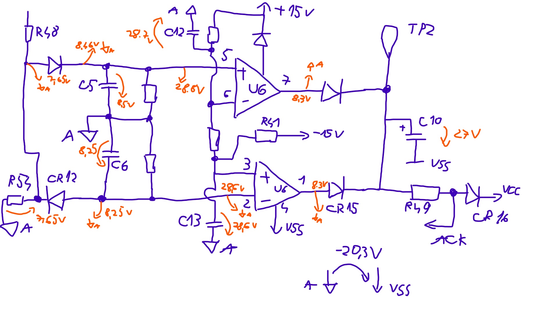
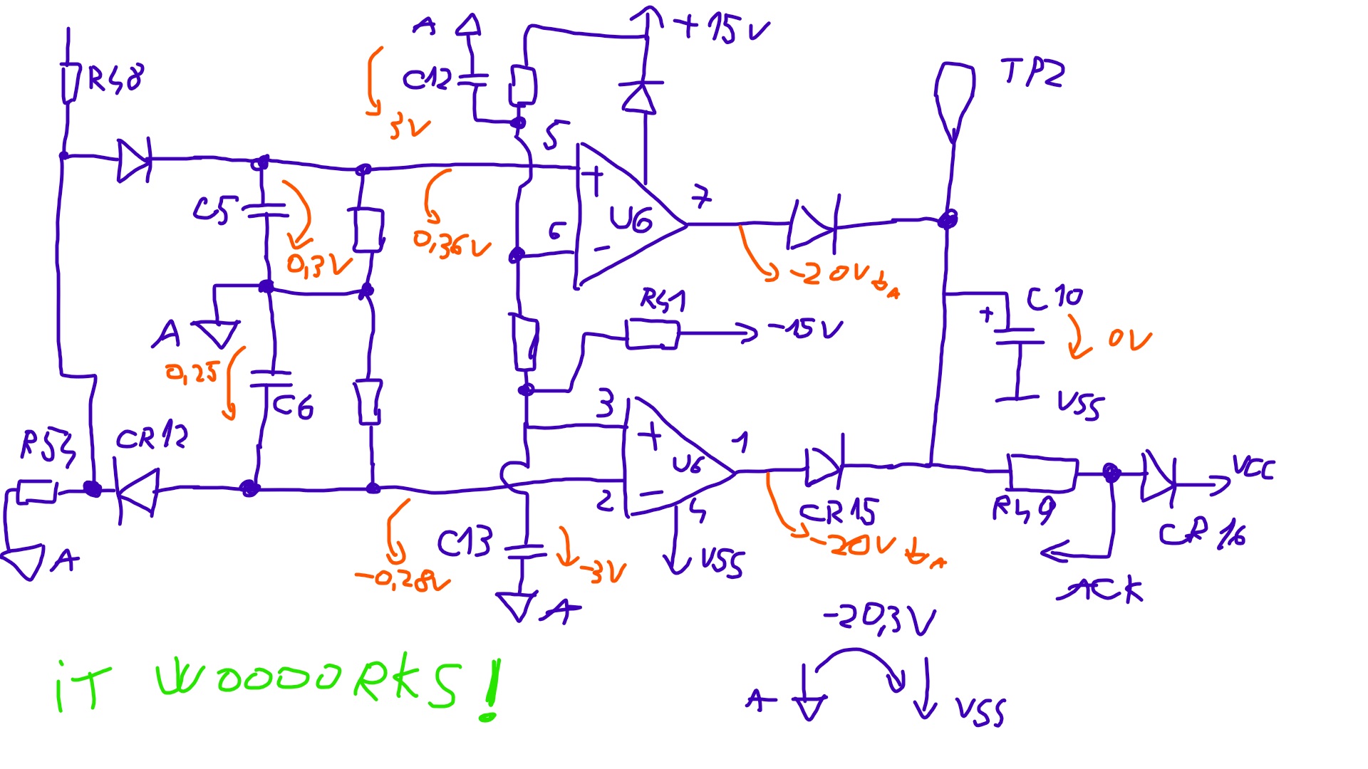
At the top, you can see the measurement bus (HI and LO inputs), followed by some diode protection (CR5 to CR10) and some over-voltage protection (U6 and C10) circuitry.
Now, U6 is configures as a window comparator, so any voltage over a certain threshold will trigger the circuit which in turn will charge C10.
First thing I checked was the voltage across C10. 27 V. That’s a lot of volts on there. But with so many rails around and ground not being actual ground on this board, are those 27 volts OK or is that above the failure threshold? So next logic thing to check was which output of the comparator went “high”. And we can see the voltages on pins 2 and 5 are more or less the same. How about the outputs of the comparators ? Nothing strange there. Pins 1 and 7 have the same value, 8.3 V. Oh, I also placed near the voltage measurements a tiny analog ground symbol, so it’s obvious to which rail I referenced the measurement. Because there’s a bit of potential between Analog GND and VSS, I figures having my own “reference ground” will serve me fine for future measurements.
Things at this point were kind of getting weird. The comparator didn’t seem to trip, yet there were 27 volts on C10. After some head-scratching, I took out C10 and measured it, just to be sure. It checked out OK. Also nothing too weird happening further up the comparators’ inputs. So, I was leaning at this point towards just changing U6 because I had a gut feeling something inside it went horribly wrong.
Luckily enough, I happened to have some old LM358 in my junk bin, so I took out the suspected chip, put in a socket, because my gut told me I’d revisit this a few times (I really hate myself for being right sometimes) and proceeded to put in a new old chip.
Moment of truth…. Of course, I had no expectation of it working, but there it was…. the digit “3” on the DMM.
Huh, that simple?! But not being satisfied by my own pat on the back and the adrenaline surge, I left the DMM on the current range to run over night.
18 hours later, Error 9 was back with a vengeance. Dang it! OK, back to square 1. Took the module back out, put in my monstrosity of a card extender and started in the most obvious place: U6.
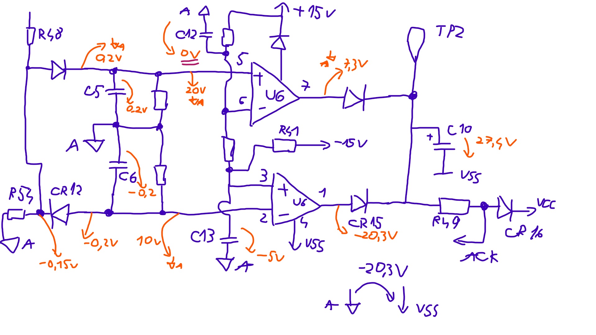
The voltage across C10 was again about 27 V. Because it actually worked for a few hours, it meant that the new U6 probably made some almost failing component bite the big one. So I was probably looking for something (hopefully not U6 again) resembling a smoking gun. Just to address the elephant in the room, yes, I replaced U6 again, with another new old chip, and sure enough that was not the culprit this time. Ok, back to measuring node voltages. Did the same set of measurements like before and again, I started looking at the inputs of the comparators. -5V on pin 2 and 20V on pin 5. Yep, definitely something wrong here. Stranger still, was that the voltage on pin 6 was 0V and -5V on pin 3. Did the magic smoke escape from something else?
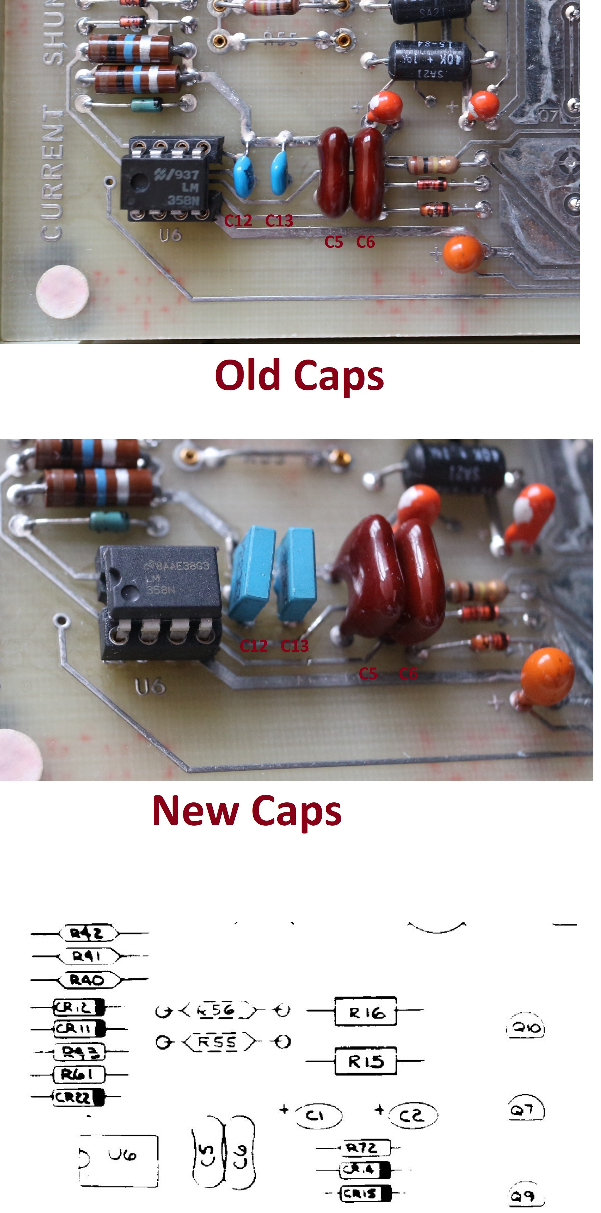
The most obvious choice was to take out C12 and C13 (which, by the way, are in Fluke’s schematic but not on the board layout drawing) and see if those might be the guilty party.
Sure enough, age took its toll on the poor caps, so much so that my meter couldn’t really tell if those were indeed caps or shorts or resistors.
In the picture below I’ve measured the circuit in its working state. Those are the correct node voltages the circuit is supposed to have and I’m putting this here more because the Service Manual does mentions these anywhere and this might be useful to someone, somewhere in the future.
That wraps this one up.
AC RMS Converter Repair
One down, one more to go.
The issue here is that the module displays a flashing “HHHHHHH” reading on every range.
So either something was shorted in one of the stages or something is causing an op-amp to hit the rails. I’m betting my money on the unobtanium JFETs again. We all know Murphy likes to give you the most trouble possible.
The AC RMS converter is basically made up of three stages, that in the end output an RMS value for whatever amplitude signal you input. The first stage is the Range Amplifier, which brings the input signal down (or up) in amplitude to about 1V (composed of Q1 and U3). The signal is then passed to the second stage, made up of the Balance Amplifier (U4 and Q10), which converts the signal to its absolute value. The remaining Squaring Amplifier, Integrator and Square Root Amplifier that make up the last stage is where all the maths happen and these will output a signal which is (this will be a mouthful) the square root of the integral of the square of the current in the emitters of Q8A and Q12A. Not going into too much detail here, as the service manual has a more in-depth explanation.
So, since the issue is with the signal being seen as “High”, the first and most obvious place to start measuring is at the output of the Range amplifier (pin 4 of U3), where I was expecting to find ~1V. However, in actuality this was at 13.3 V. Definitely not OK. Knowing that the caps on the Current Shunts module failed on me, I took out C7 and C40 to measure them. These tured out OK. Then, I went upstream of U3, trying to see if there was something forcing it high like that. But there wasn’t much to measure. Relay K1 disconnected every time right after the error appeared, so no chance something on the bus actually causing those 13.3 V and Q1 also seemed a pretty happy camper. So it was pretty obvious the culprit here was U3. Again, going with my gut, I looked through my junk pile and put in a nice TO-99 socket and fitted in the closest pin-compatible part I could find, an LM741. Yeah, I have a pretty big junk box(s).
So, who’s betting on it working first go?
Huh, that was easy.
So that means my job’s done here. Ok, I know there’s a huge offset in the reading, but that’s because I have a totally different op-amp in there. Also, once I have a sgnal hooked up to the inputs, it measures it pretty OK.
Epilogue
This article is not so much about the repair itself, but about showing you around the 8505A and also about showing how my process of debugging and repair went. As you can see, I like to poke around first, measure voltages and most important, write everything down. Paper or digital, you decide, but it’s useful to have a record of what you did and most importantly, how you did it. For example, take those hand-drawn schematics; there were three times that I went in, knees deep in transistors and took measurements of the same points then compared them, to see what’s changed and deduce where the issue might actually be. Also, I hope the tour of the 8505A will serve others and, while I’ll be the first to admit that the meter is kinda flaky in its construction and operation, it has some neat features that I think make it a nice candidate for one’s first foray into the world of single digit ‘ppms’.
Also it’s bag of tricks is quite impressive, having 7½-digit capability as well as being able to give you direct reading of division ratios when using an external reference. This last little trick is especially handy for trying to figure out how stable your DIY Hamon divider is when you only have a noisy LM399 handy. These, coupled with the fact that you can get it at about 100 to 200 dollars and nice low-noise SZA263 voltage reference (TiN: very same used in mighty Fluke 5720A/5730A or 8508A), make it a real winner.
Projects like this are born from passion and a desire to share how things work. Education is the foundation of a healthy society - especially important in today's volatile world. xDevs began as a personal project notepad in Kherson, Ukraine back in 2008 and has grown with support of passionate readers just like you. There are no (and never will be) any ads, sponsors or shareholders behind xDevs.com, just a commitment to inspire and help learning. If you are in a position to help others like us, please consider supporting xDevs.com’s home-country Ukraine in its defense of freedom to speak, freedom to live in peace and freedom to choose their way. You can use official site to support Ukraine – United24 or Help99. Every cent counts.
Modified: Oct. 26, 2019, 4:13 a.m.

