Intro
Every good instrument have some feature or performance parameter that makes it special. For HP/Agilent/Keysight 3458A DMM such special thing is unrivaled DC Voltage performance and ADC linearity which make some very nice tricks such as Artifact calibration and self-calibration from just three input reference standards (zero, 10 VDC standard, 10 kΩ standard). For Keithley 2002 such special feature is super-compact size, various scanner modules and unique sub-nanovolt option Keithley 1801. And for Fluke 8508A such special feature is electronically controlled front/rear input ports and ratiometric measurement mode. But this feature sadly does not come standard, but made optional by Fluke for lot of gold.
Original Fluke 8508A 8½-digit DMM that was selling for MSRP north of $17k shipped with just front terminals. Pretty common rear interface functionality, useful for comparison different measurands or in automated setups when instrument installed in the rack are available only as an option. This option is called Fluke 8508A/001 and can be added to the already expensive DMM for “just” $7k USD. Fully featured 8508A as result had invoice price about $24k USD, hefty sum enough to buy you two brand new Keysight 3458As and some change for cables/shipping/tax. :)
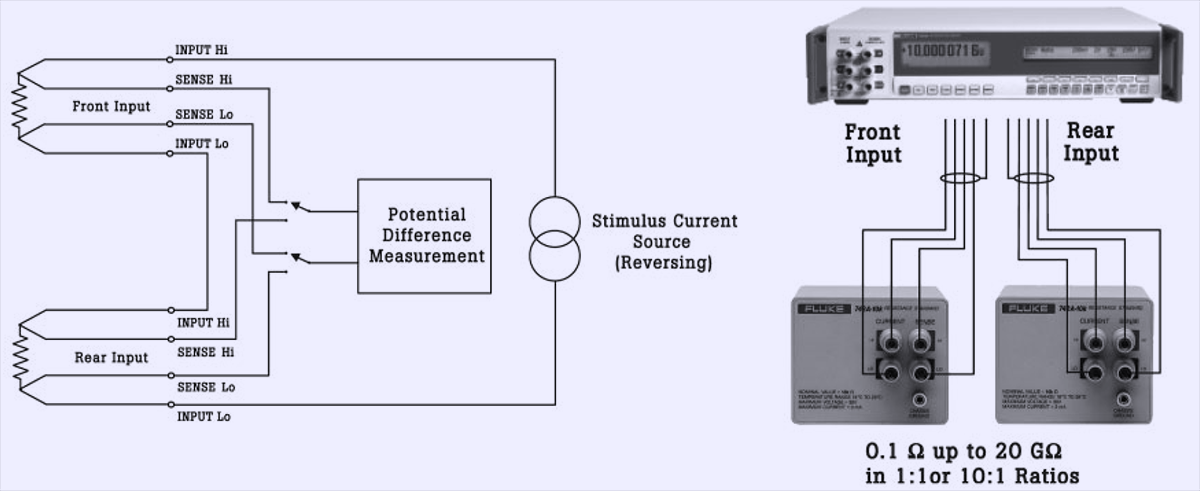
Provision in resistance function to route same current source thru both front and rear terminals is unique feature of 8508A (and newer 8588A released in 2019). This can be very handy to perform automated comparisons of unknown resistance and voltage standard versus reference standard connected to other terminal pair, which makes 8508A one of the common instruments found in resistance metrology labs.
Among 8½-digit meters only older and better Datron 1281 offered better flexibility with not just front and rear but even two rear inputs and one front input, also with remote programming ability. But worry no more, we can add this to standard 8508A for 1/10th of the cost by doing modification here. A fellow volt-nut sent me his broken Fluke 8508A to perform repairs and add Option 001.
Disclaimer
Redistribution and use of this article or any images or files referenced in it, in source and binary forms, with or without modification, are permitted provided that the following conditions are met:
- Redistributions of article must retain the above copyright notice, this list of conditions, link to this page (https://xdevs.com/article/f8508a_001/) and the following disclaimer.
- Redistributions of files in binary form must reproduce the above copyright notice, this list of conditions, link to this page (https://xdevs.com/article/f8505a_001/), and the following disclaimer in the documentation and/or other materials provided with the distribution, for example Readme file.
All information posted here is hosted just for education purposes and provided AS IS. In no event shall the author, xDevs.com site, or Fluke or any other 3rd party be liable for any special, direct, indirect, or consequential damages or any damages whatsoever resulting from loss of use, data or profits, whether in an action of contract, negligence or other tortuous action, arising out of or in connection with the use or performance of information published here.
If you willing to contribute or have interesting documentation to share regarding pressure measurements or metrology and electronics in general, you can do so by following these simple instructions.
Keep in mind that any alterations or modifications for your Fluke 8508A would not be covered by manufacturer repair and service agreements, and would void any calibration or history accumulated on the altered instrument. You are warned. Article here shows experiment for educational purpose.
Hardware overview and modification process for Option 001
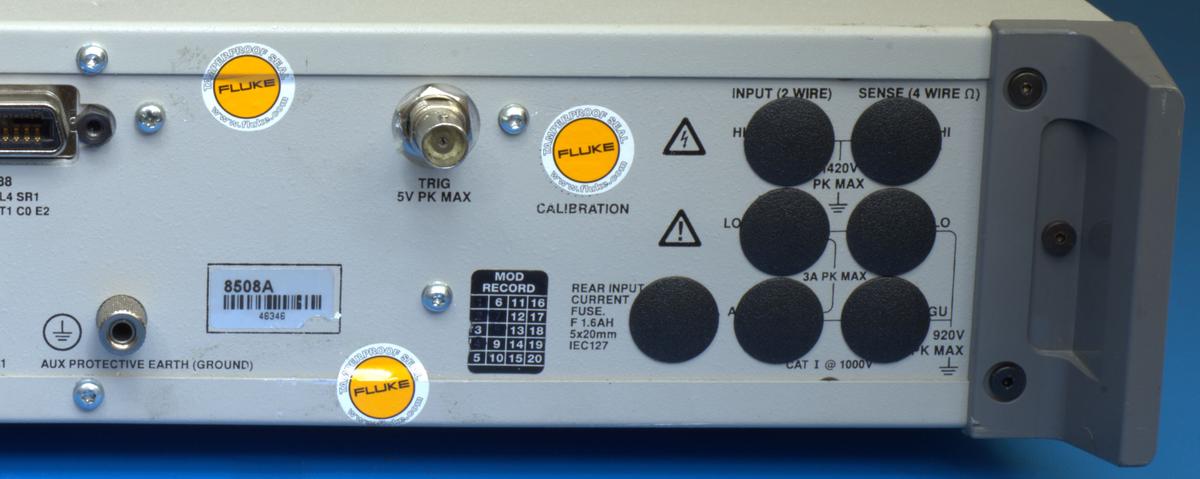
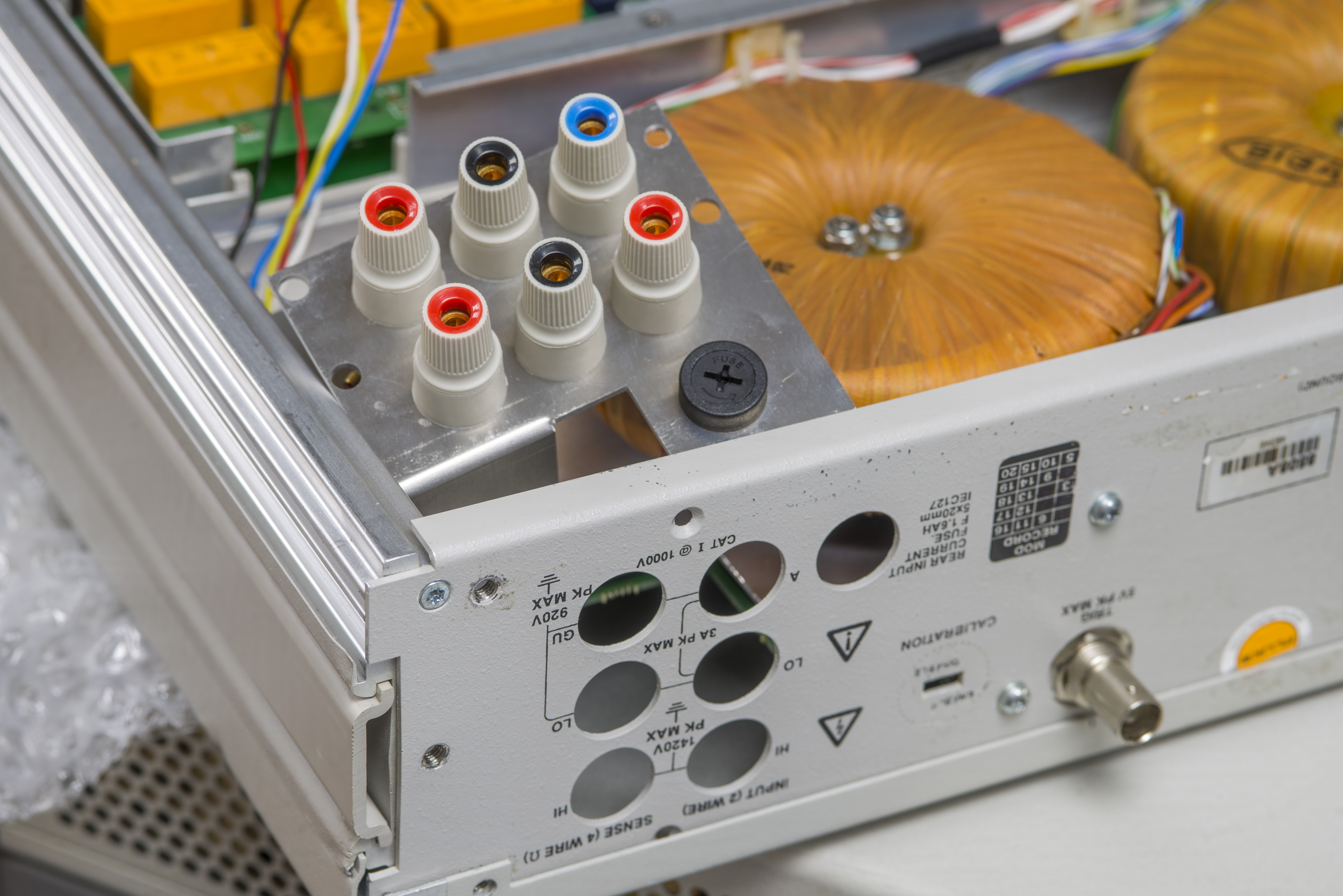
Here how “normal” 8508A rear side looks like, with dummy plastic plugs instead of nice terminals. We will modify it to add rear terminal option and perform some tests, showing benefits such modification provides.
So to add the option into the instrument, we will need to acquire and install missing 5-way low thermal posts, add missing internal switching hardware, some high-quality wiring and recalibrate the instrument with both front and rear connections. Below is drawing diagram from Fluke 8508A service manual, to give an idea what we need to replicate:
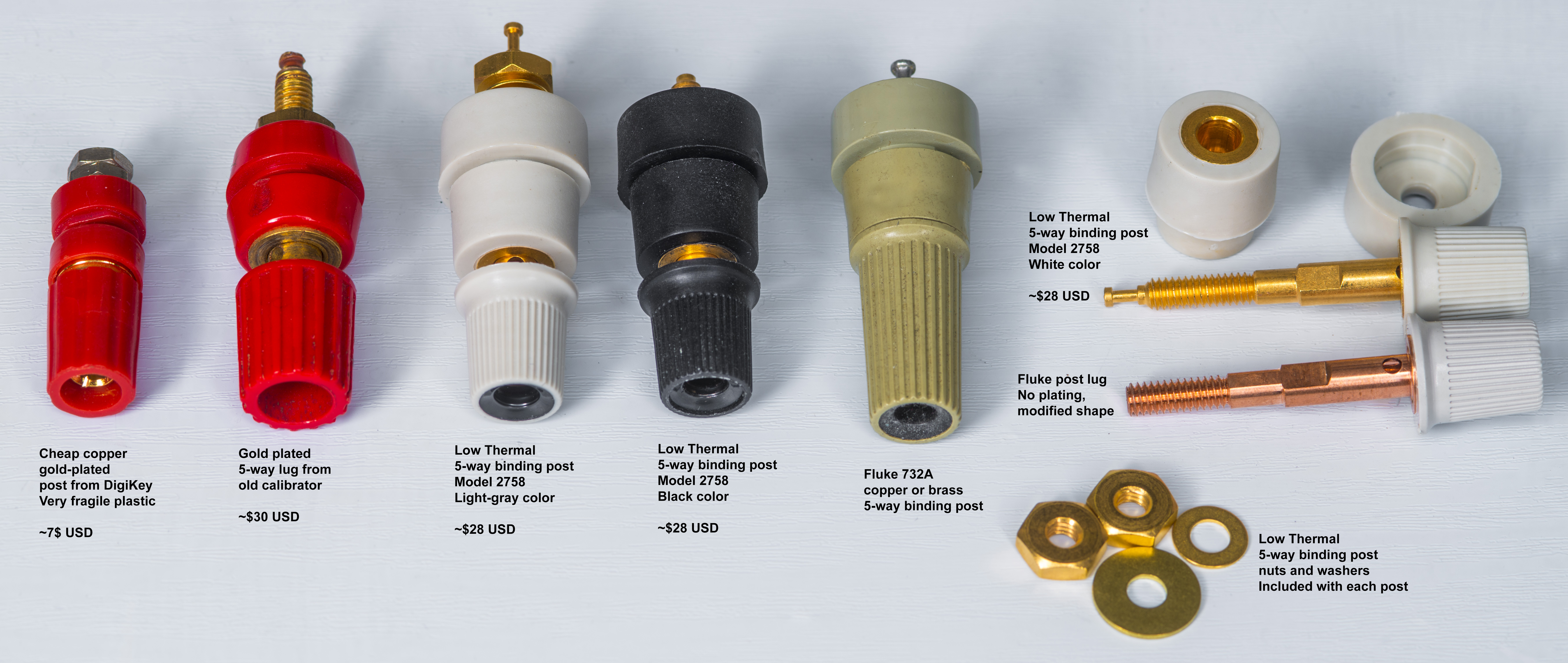
First thing first, buy the terminals. Low Thermal manufacture and offer almost identical 5-way copper high quality terminals that are almost perfect match to original Fluke non-plated parts. There is no MOQ for order, you can even buy 1 connector for your project.
They are not cheap at $25-$30 USD per piece but given the cost of even basic 8508A it’s expense well deserved. Low Thermal manufacture both black nylon plastic and beige-gray variant. Here we go with gray posts to match the terminals used on the front of the DMM.
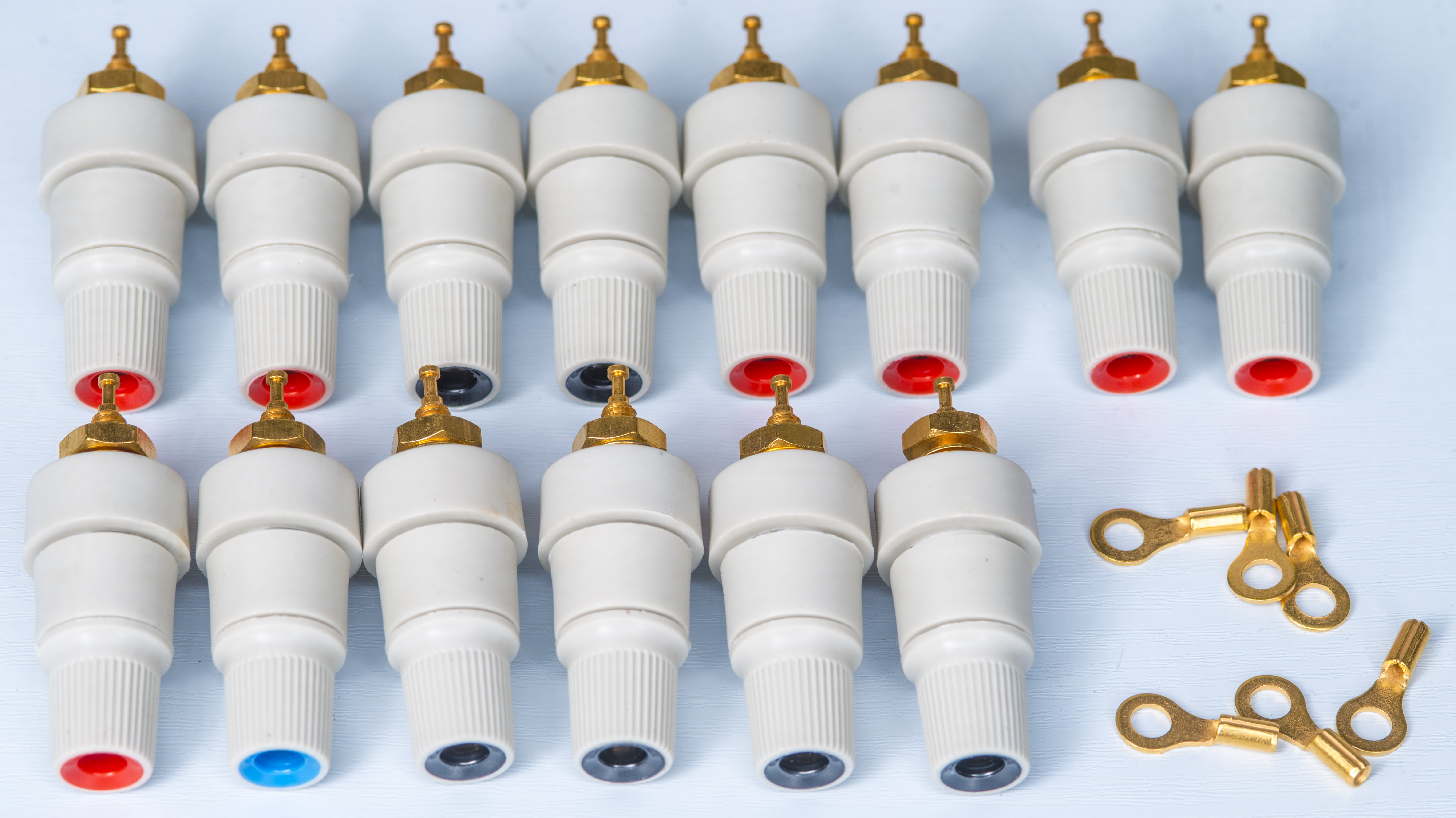
In comparison some other terminals shown on photograph below.
To mount posts we need additional metal bracket that mounts on inner chassis frame and hold terminals in place.
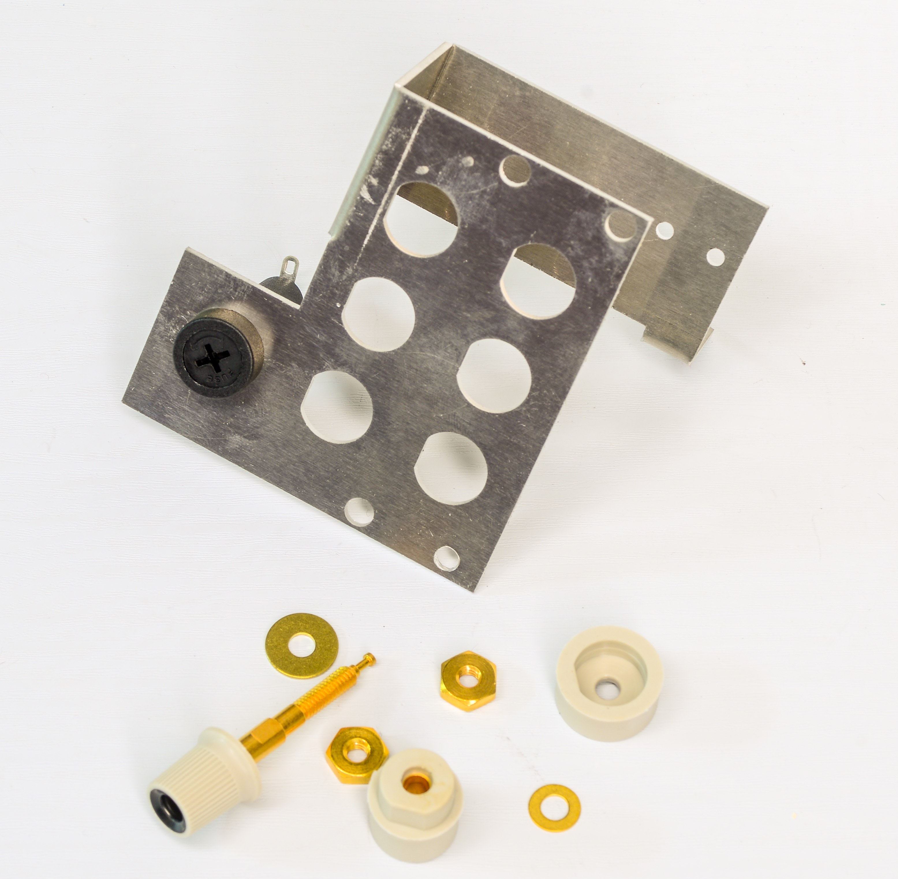
This bracket was specially designed and made by our metrology friends. It is stainless steel part with few bends on it.

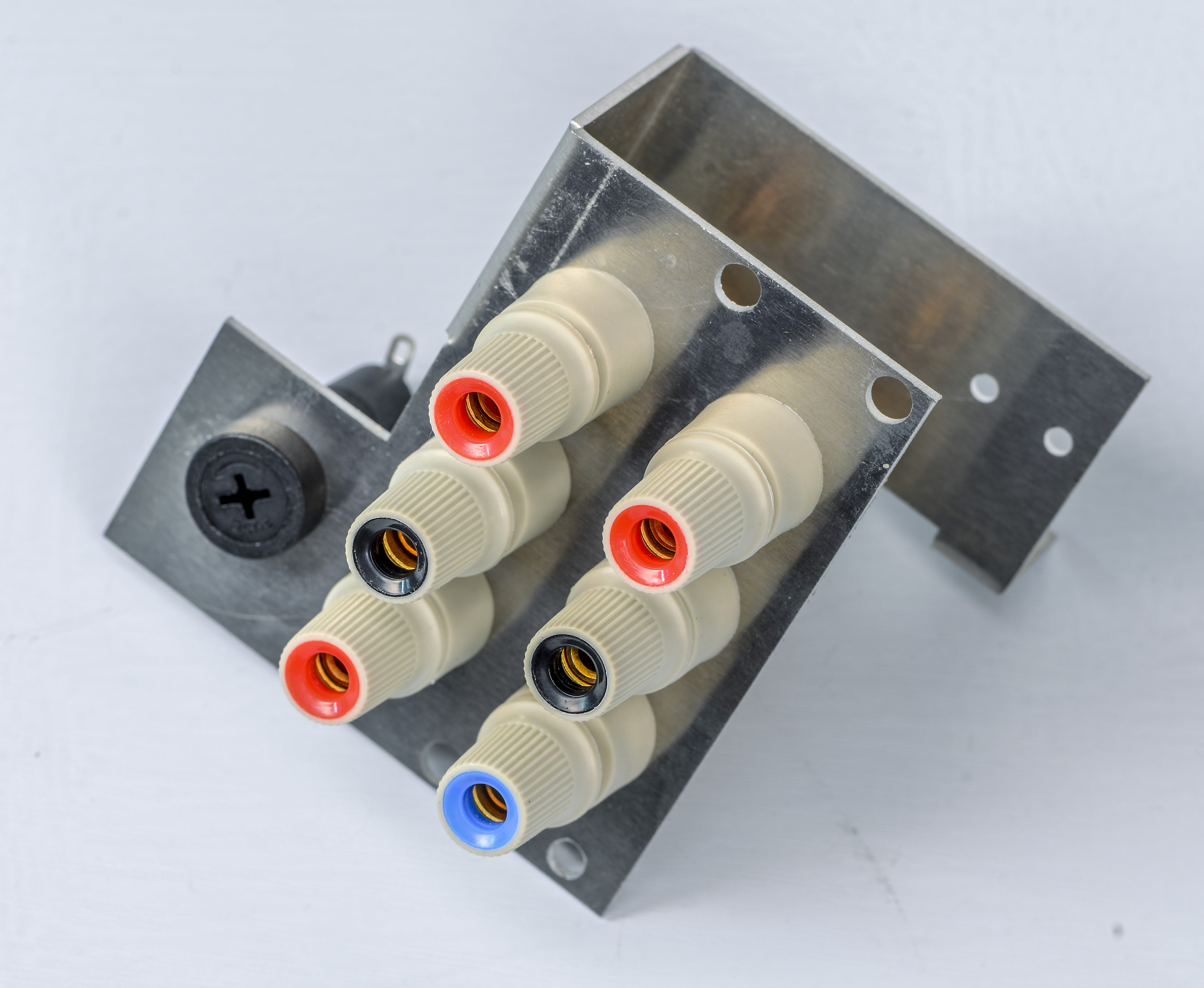
Terminals fit very nice, no problems during assembly.
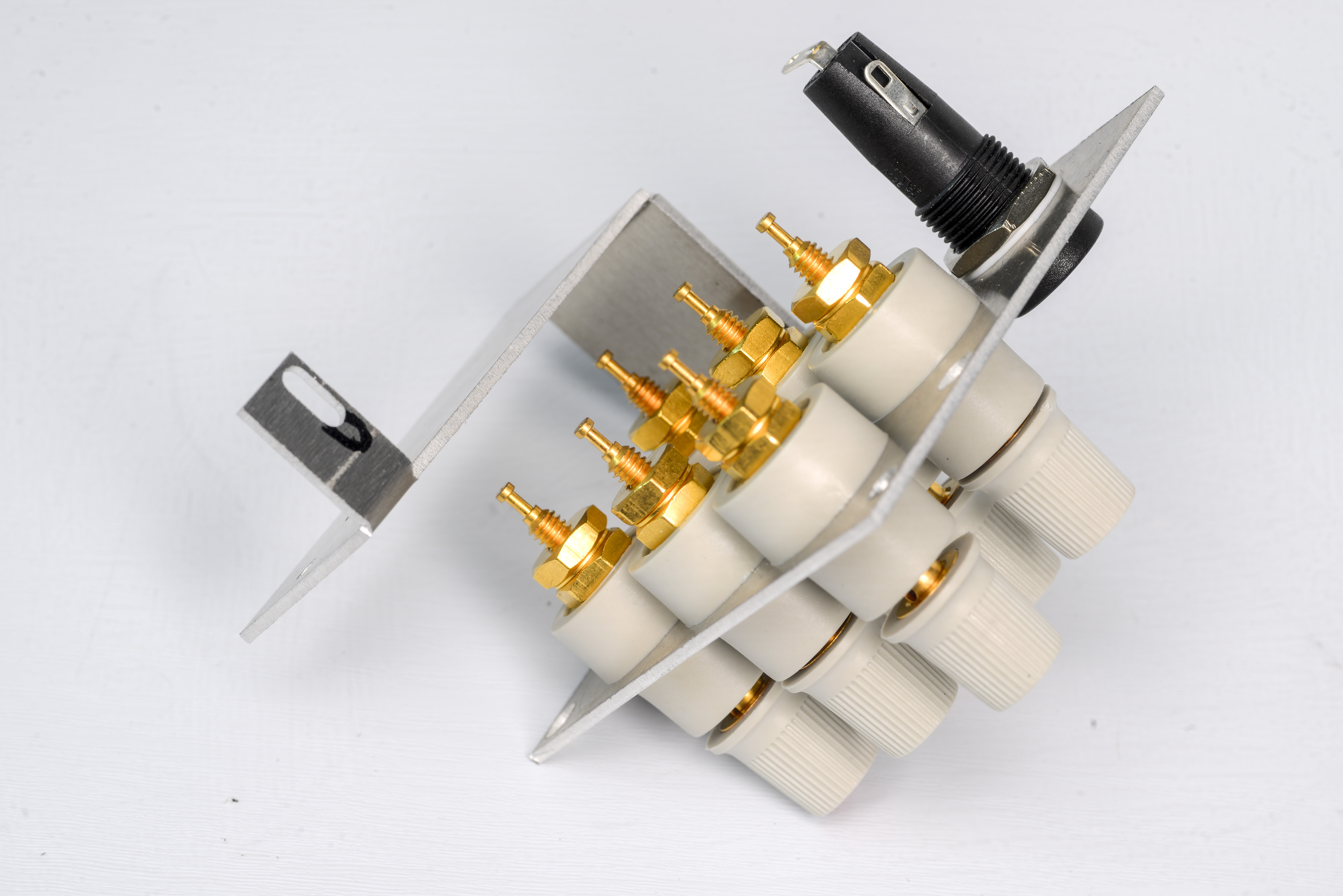
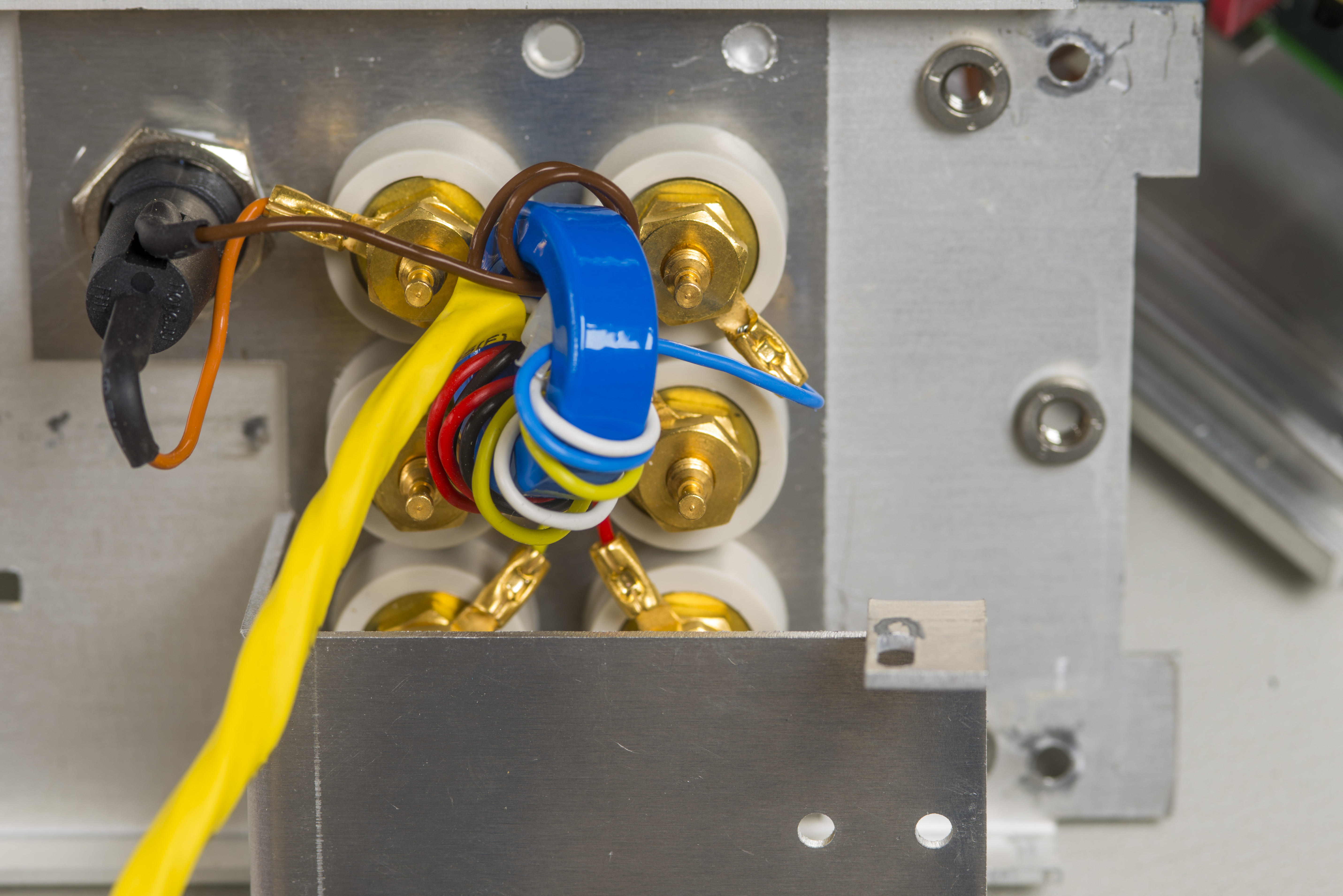
All posts in place. To attach posts we will use solder-free connection with spade ring terminations and crimper. Wire to be used in this interconnect is copper silver-plated PTFE-insulated AWG14 type.
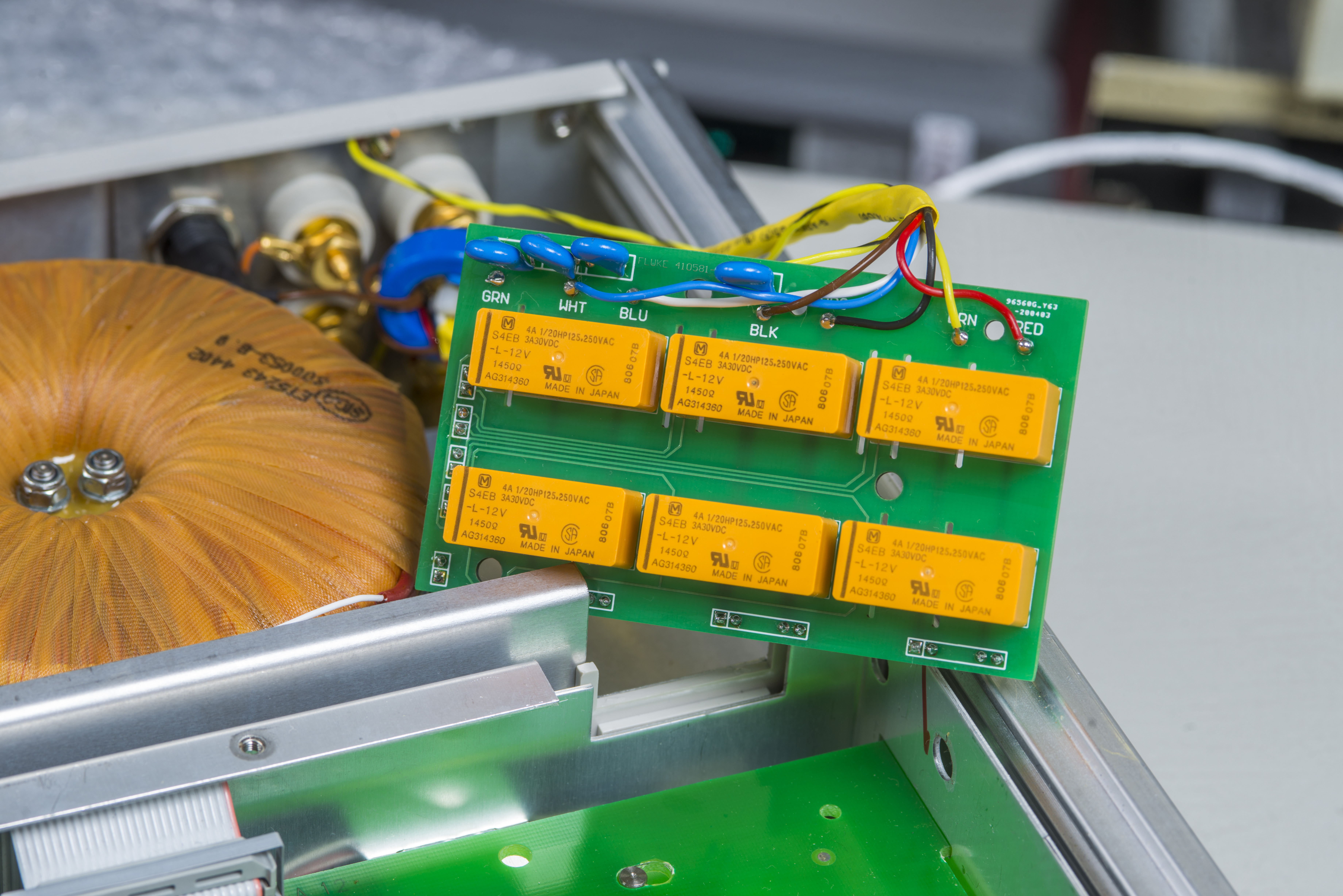
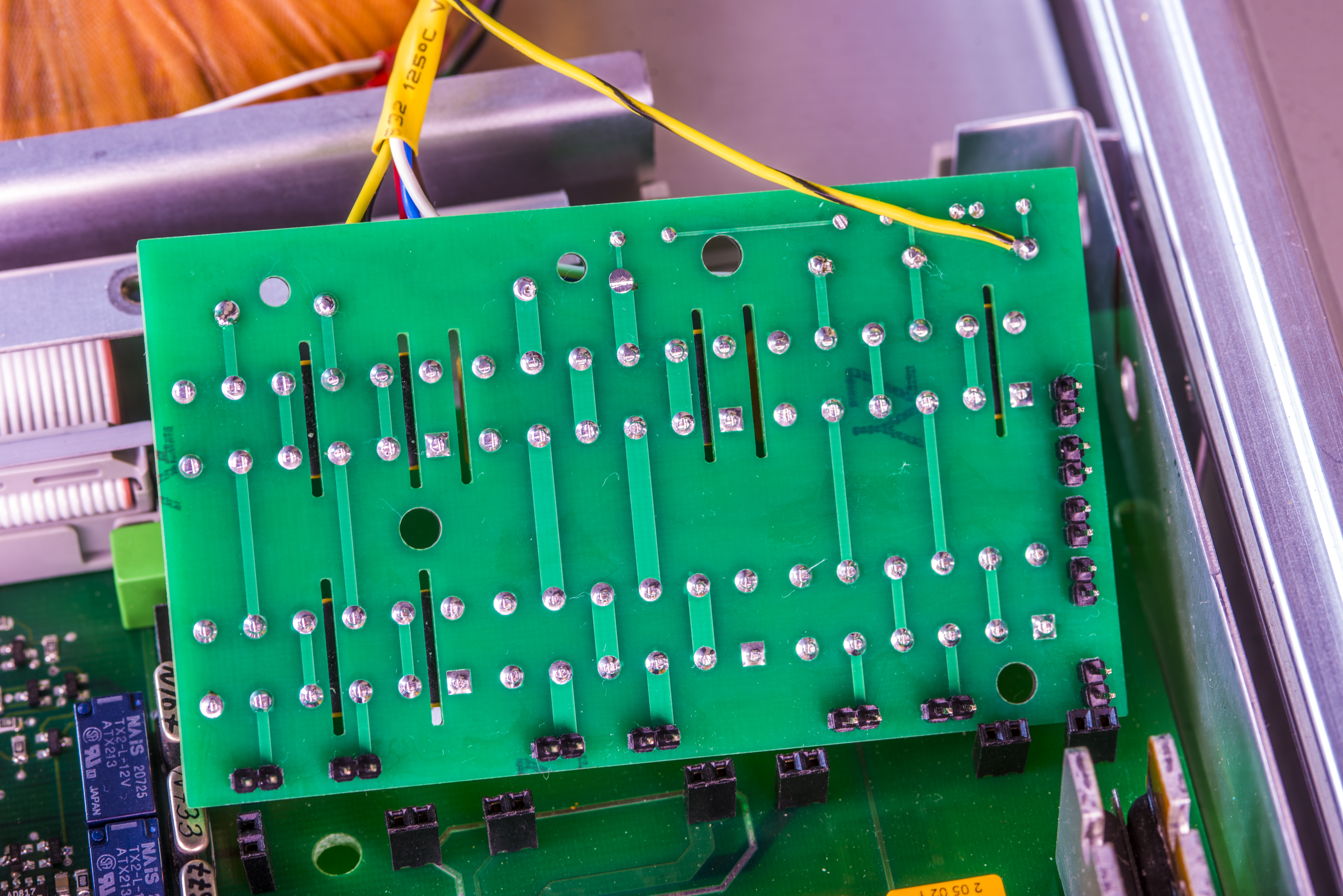
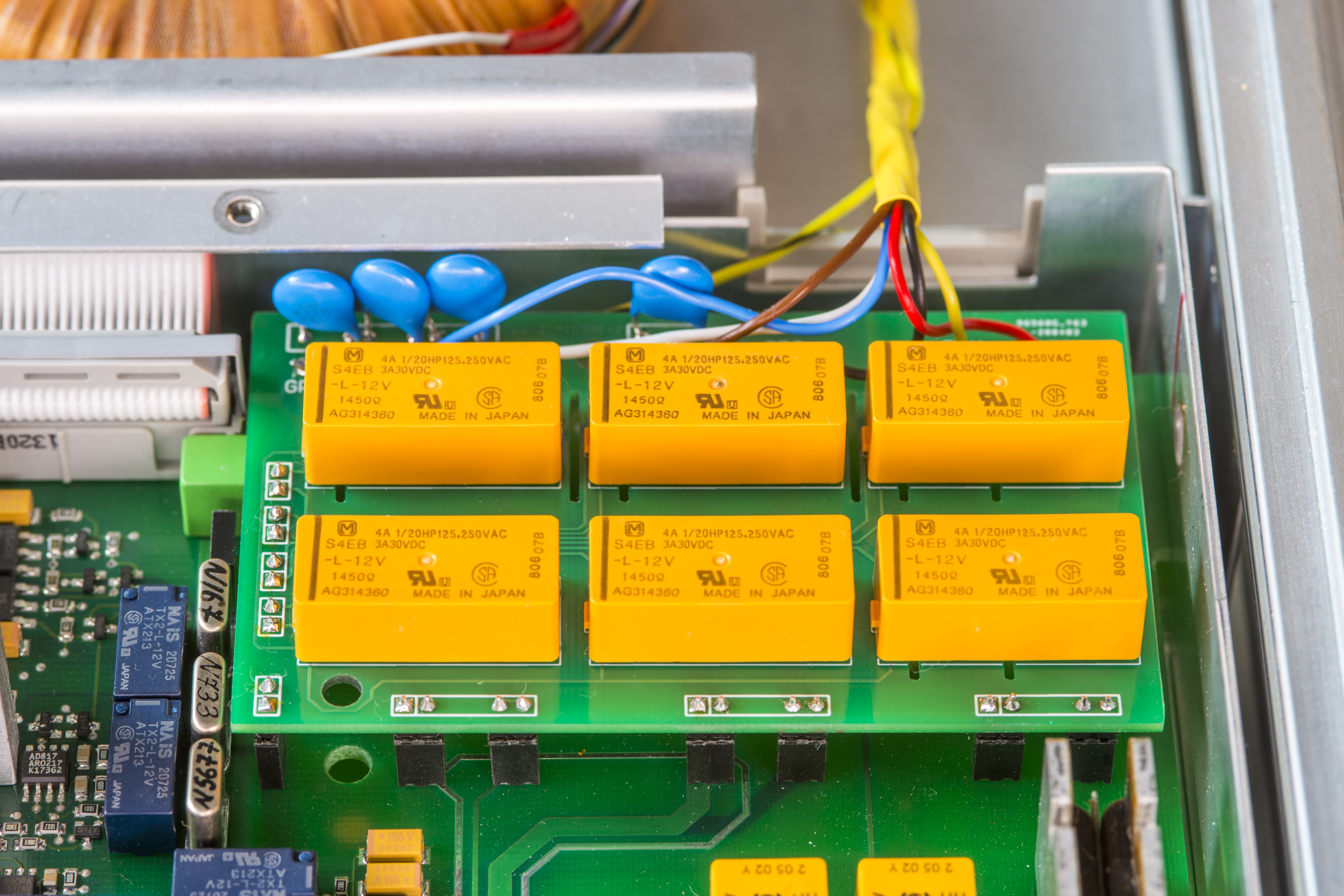
Now the electronics side. PCB is rather simple 2-layer board that use six latching relays to route HI/LO and Sense HI/LO signals between rear, front posts and motherboard depending on measurement function. Current input on the rear supports only up to 3A range and has own fuse. Bare PCB photos shown below.
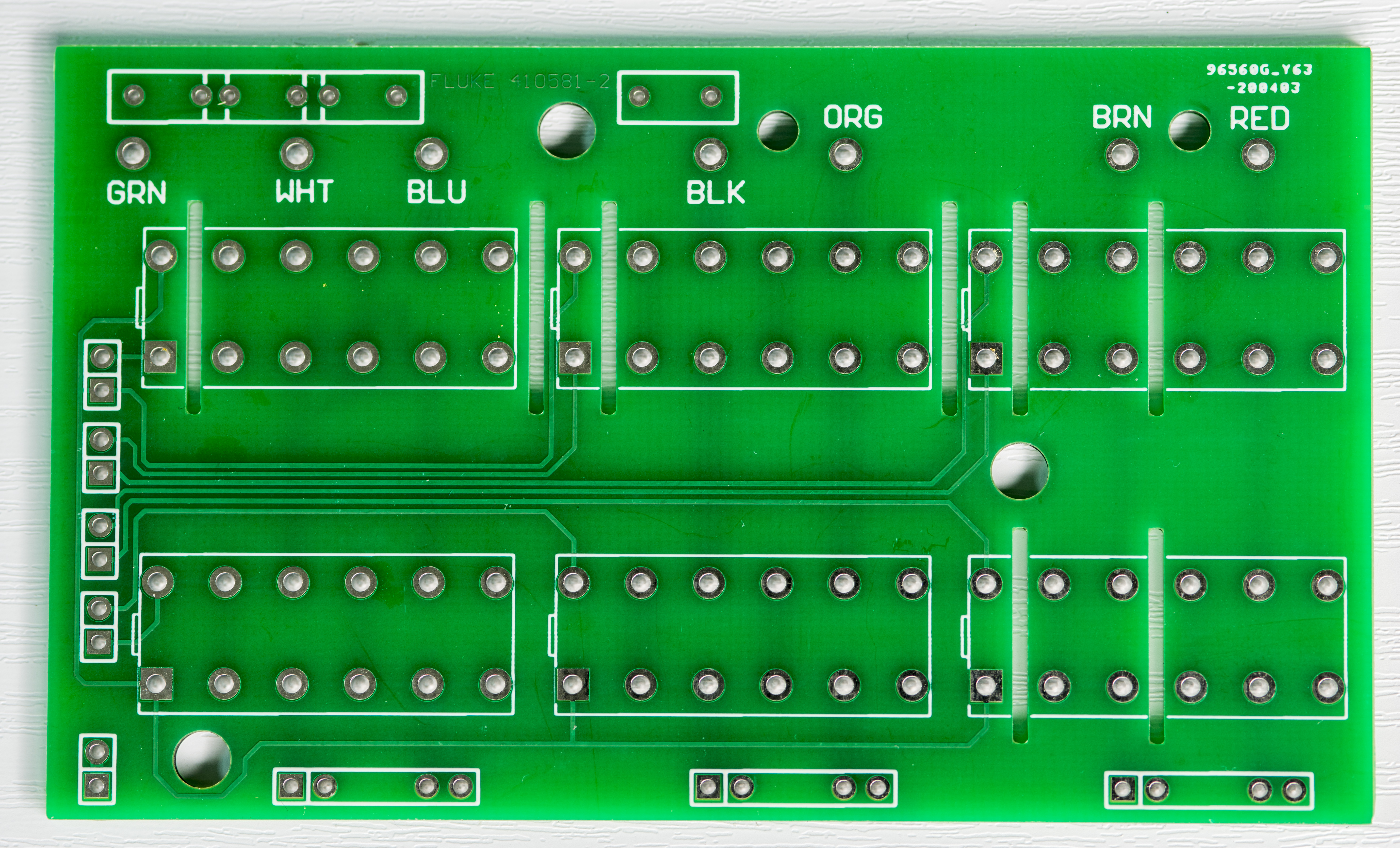
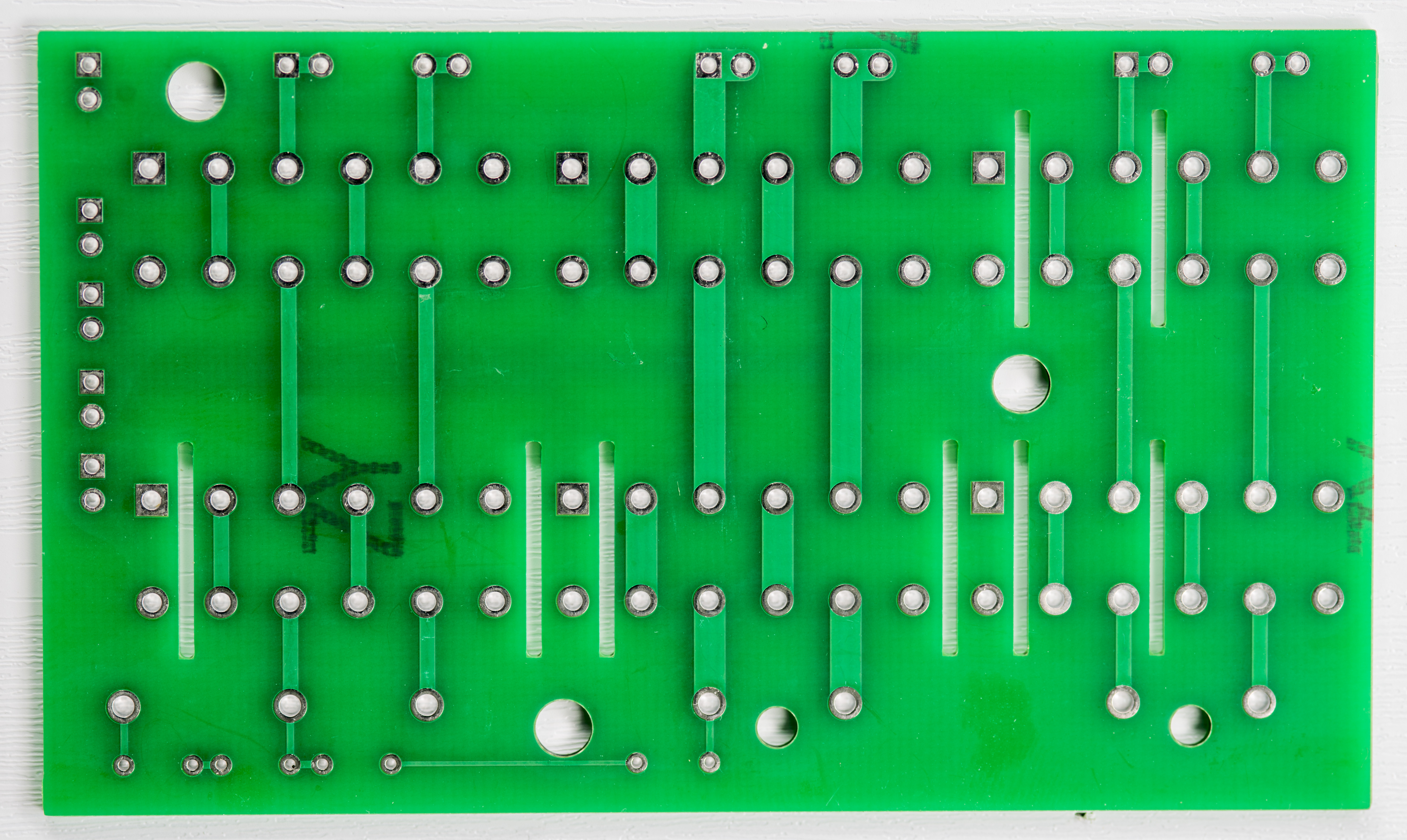
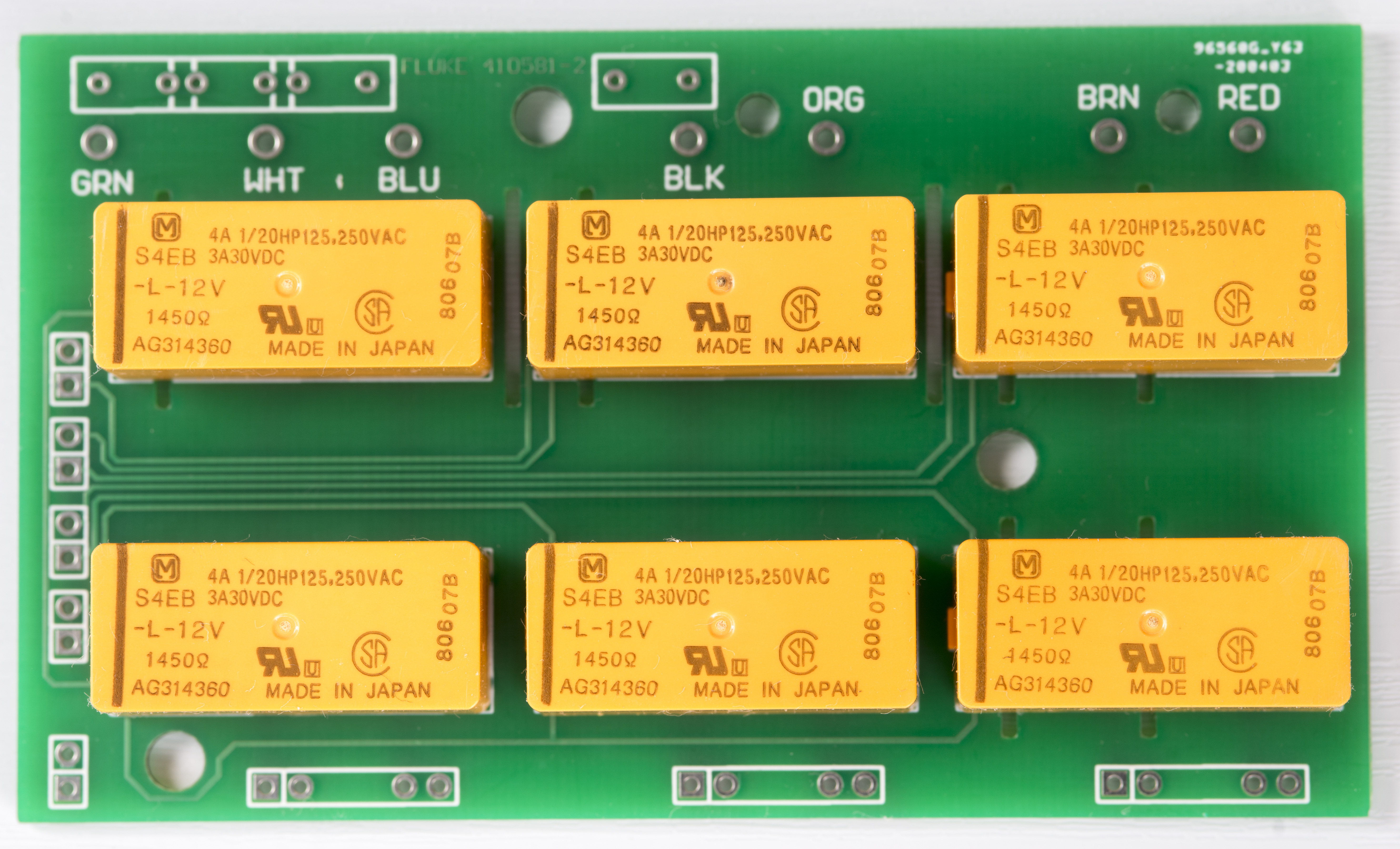
Here is the board look with only relays populated so far:

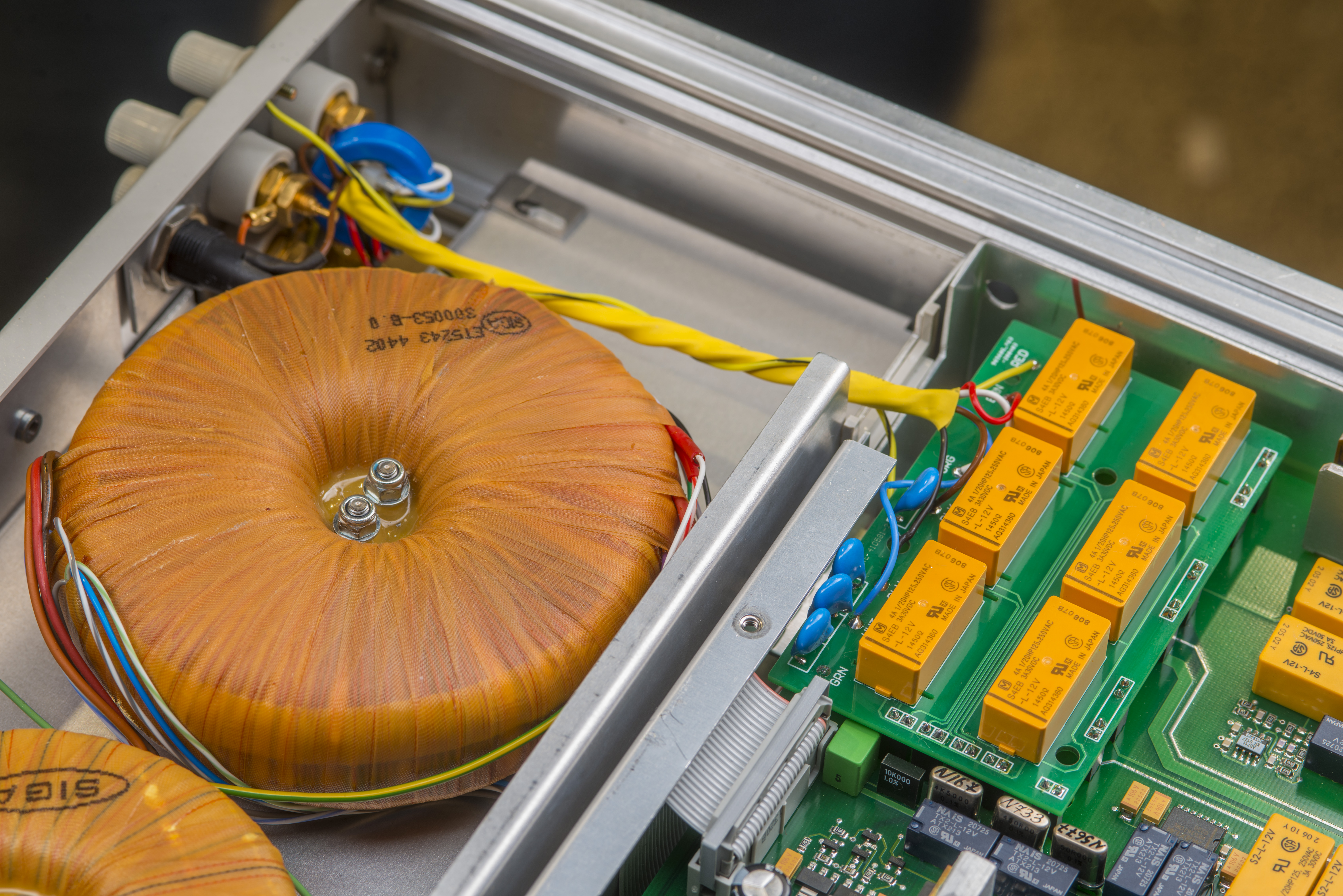
Test fit of the PCB on the analog mainboard inside Fluke 8508A. Board is missing high-voltage capacitors and wiring is not there yet.

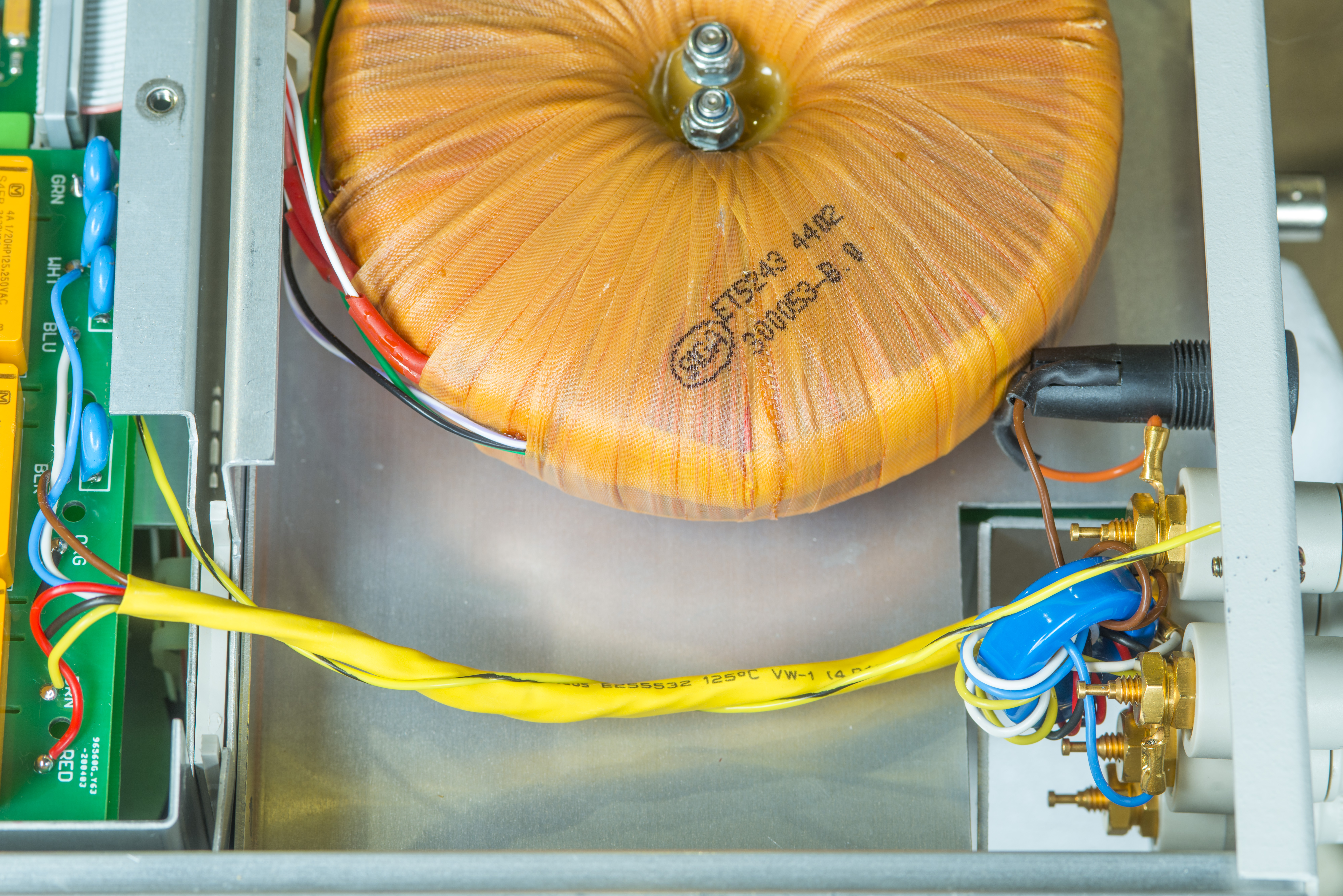
Rear panel must be removed first to install terminals and mechanical bracket, otherwise secondary transformer chassis frame are in the way.
Just like original Fluke 8508A/001 option we put common mode rejection choke with two turns of all rear signals thru it. All wires are high-quality silver-plated copper with measured insulation resistance over 250 TΩ with Keithley 6430.

Rear current input rated only up to 2 ampere current, so used AWG18 wire is enough for this application. After wire used in Fluke 5720A for same current is even smaller :)

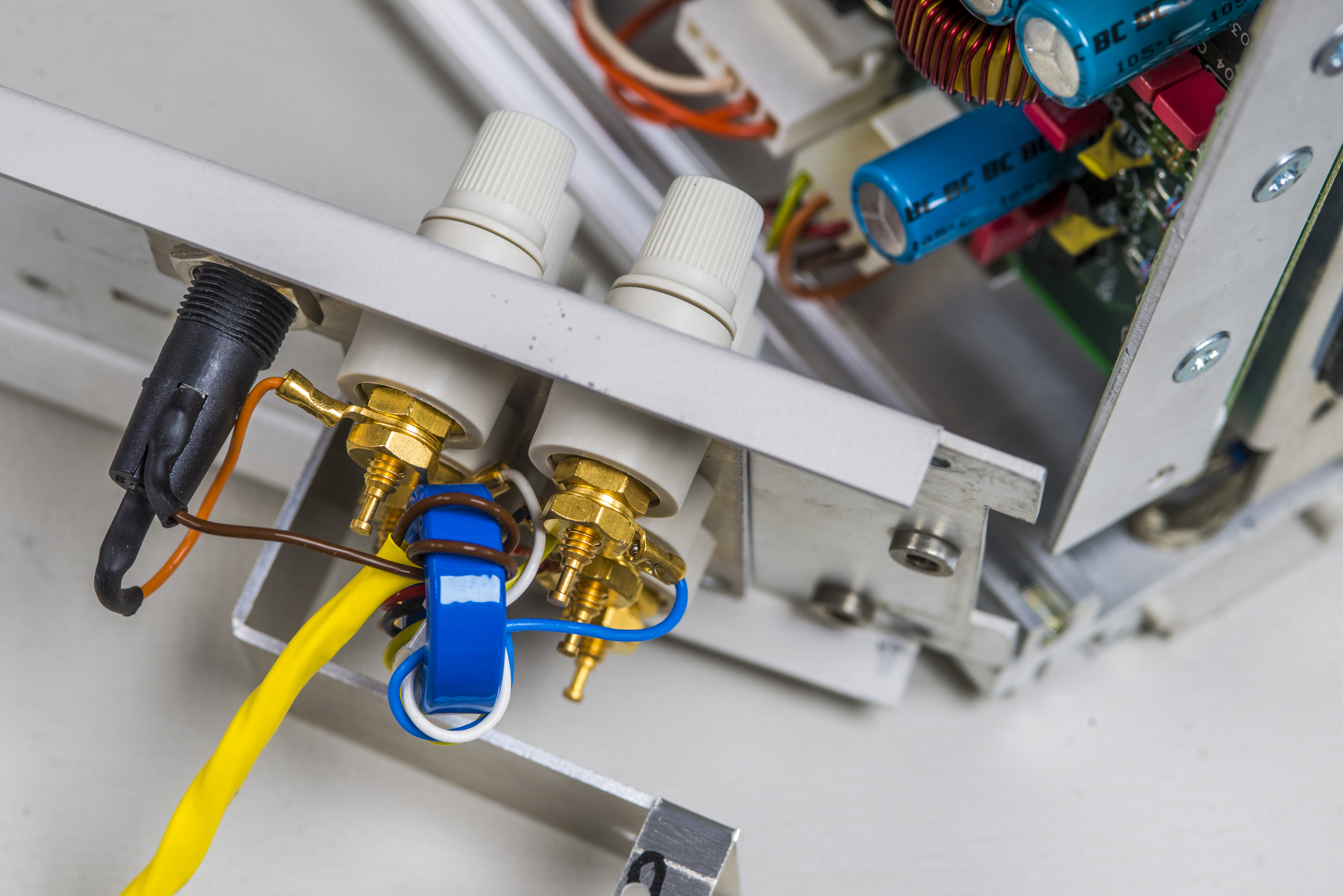
Fuse holder happened to be a bit problematic, as it was actually touching with transformer and there is no gap between input terminal and transformer. Perhaps we will rectify this in future by installing shorted fuse holder.
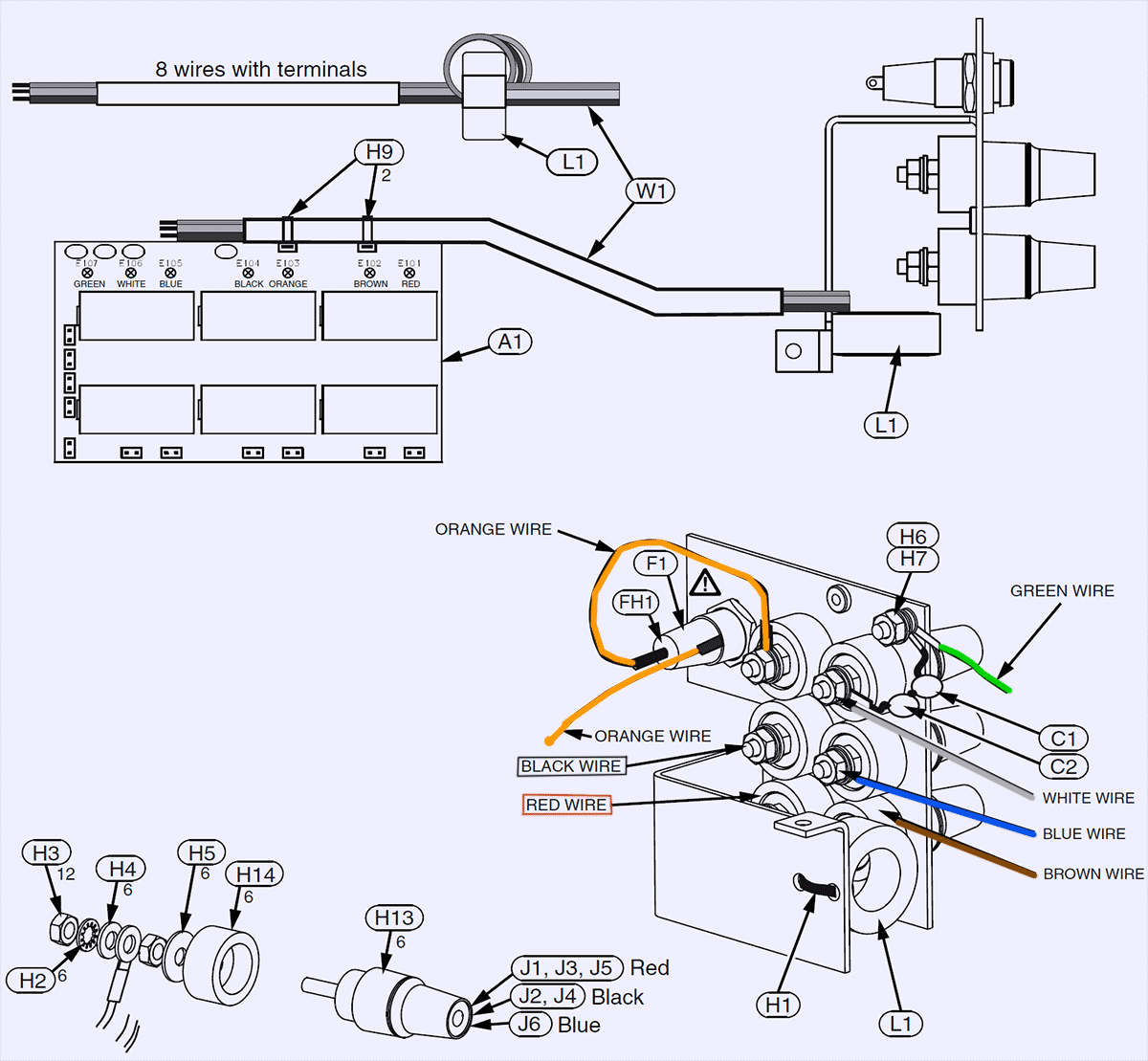
Wiring designators and purpose listed in following table.
| Signal purpose | Rear terminal | Relay board color point |
|---|---|---|
| HI input | Red, Top left | RED |
| LO input | Black, Middle left | BLK |
| HI SENSE input for 4W | Red, Top right | BRN |
| LO SENSE input for 4W | Black, Middle right | BLU |
| Current input, 2A max | Red, Bottom left | ORN |
| Guard | Blue, Bottom right | WHT |
| Earth chassis | Chassis connection | GRN |
Sharp eye may notice wiring colors on photos not matching the table. Table designators and colors are correct, photos are not. Wiring was corrected in actual instrument, but I didn’t bother to retake new updated photos.
Earth chassis wire (yellow with black stripe) is wrapped outside of signal twisted cable bunch to reduce chance of unwanted leakage.
Board installed in meter just like real Fluke’s option module. We will add plastic retention clip standoff later as well.
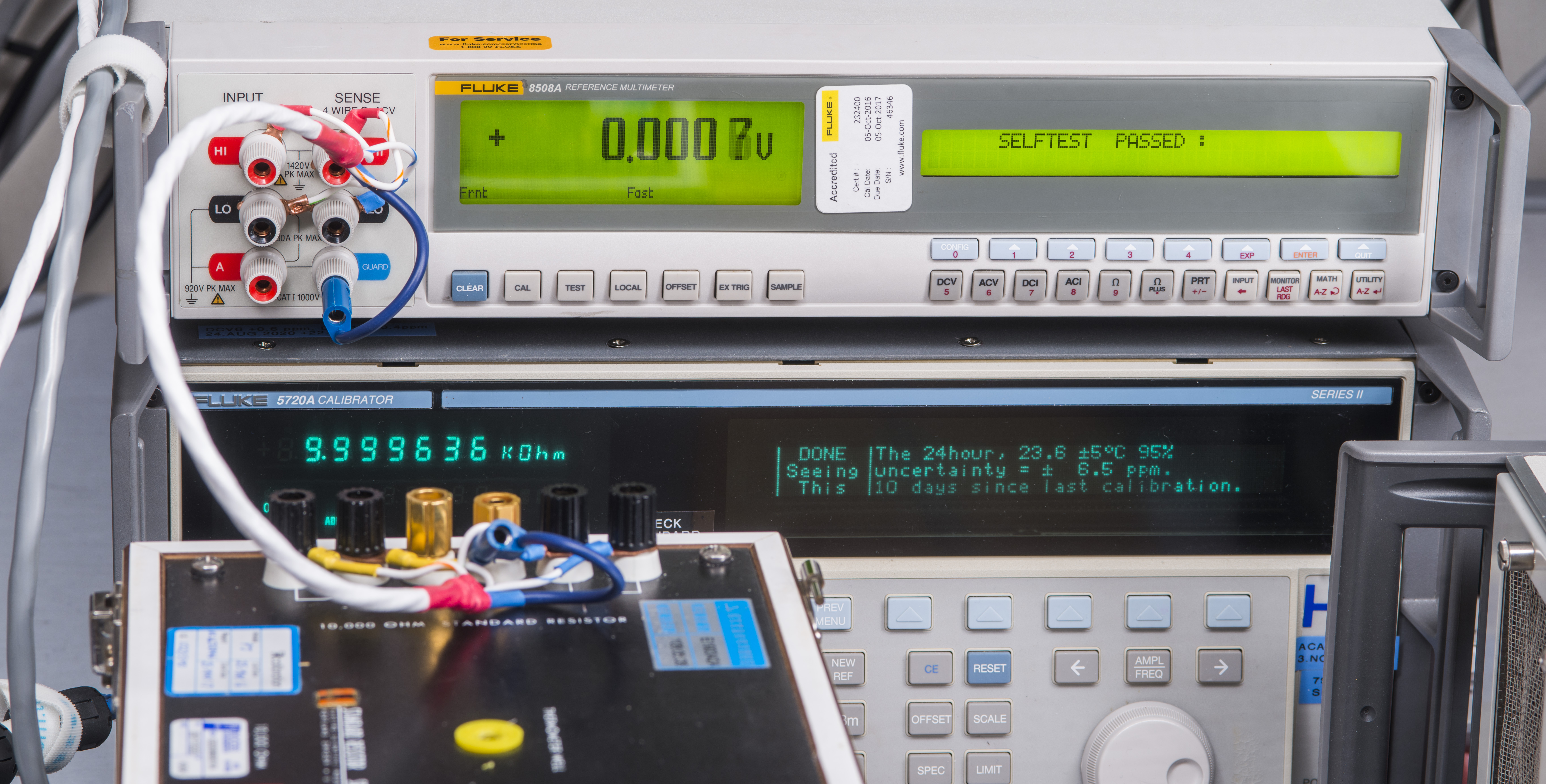
After reassembly and checking everything few times, power on the DMM and perform a quick self-test to ensure that overall it’s still good to go. Self-test will give confidence in full functionality of the instrument but it’s good quick sanity check.
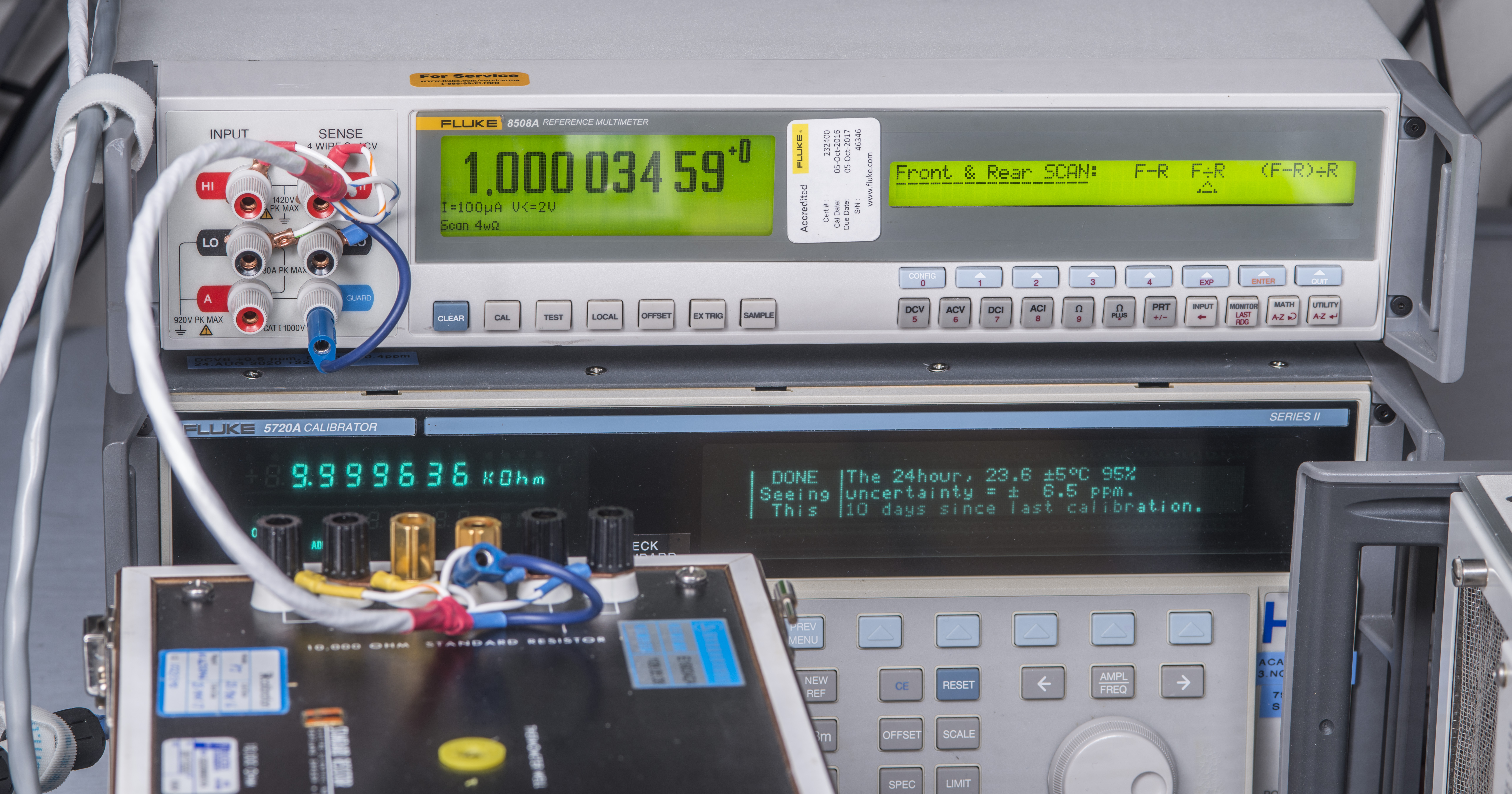
Meter with installed option now allows to select Rear input terminal or one of three Scan modes with simple automatic math operators. These modes also can be controlled remotely over GPIB at any time.

Using Rear/Front ratio mode can be helpful to quickly determine ratio between two connected standards or sources. While this can be done manually automating such stuff helps to reduce variation from wiring changes, handling cables, etc.
Some test results and benchmarks
BOM cost on used parts during this modification experiment.
| Description | Qty | Price | Supplier |
|---|---|---|---|
| Low Thermal 2758 post, red | 3 | $28 USD each | Low Thermal |
| Low Thermal 2758 post, black | 2 | $28 USD each | Low Thermal |
| Low Thermal 2758 post, blue | 1 | $28 USD each | Low Thermal |
| Metal bracket to mount posts | 1 | :) | Friends |
| Wire | 1 cable | $30 | ePay |
| F/R Relay board | 1 PCB | :) | Friends |
| Relay S4EB-L-12V | 6 pcs | $16.56 each | Digikey |
| Ceramic capacitors 470pF 1kV | 6 pcs | $12 USD | Digikey |
| Common mode choke | 1 pcs | $6 USD | Digikey |
| Full recalibration and adjustment | Priceless | xDevs.com | |
| Total cost | $490 in parts |
Projects like this are born from passion and a desire to share how things work. Education is the foundation of a healthy society - especially important in today's volatile world. xDevs began as a personal project notepad in Kherson, Ukraine back in 2008 and has grown with support of passionate readers just like you. There are no (and never will be) any ads, sponsors or shareholders behind xDevs.com, just a commitment to inspire and help learning. If you are in a position to help others like us, please consider supporting xDevs.com’s home-country Ukraine in its defense of freedom to speak, freedom to live in peace and freedom to choose their way. You can use official site to support Ukraine – United24 or Help99. Every cent counts.
Modified: Jan. 2, 2021, 6:48 a.m.