Intro
While voltage references based on LMx99 or LTZ1000CH and LTZ1000ACH are common and lot’s of information about them is available, there is less knowledge on how to setup a voltage references based on the Motorola SZA263 and the Fluke LTFLU fabricated by Linear Technology.
The main key difference between the REFAMP such as SZA263 or LTFLU and more traditional LTZ1000/LTZ1000A are:
- REFAMP has no heater built-in unlike LTZ part.
- REFAMP has the temperature compensating transistor in series with the buried zener diode, not parallel as in the LTZ design.
- Therefore the LTFLU circuit needs a lot more temperature and current compensation work from designer than LTZ1000 circuits do.
- The LTFLU/SZA263 is in a 4-pin TO-can, the LTZ1000 in an 8-pin for additional signals. They are not compatible and need different bias circuit around them.
Fluke used REFAMP (Motorola SZA263 first, Linear LTFLU later) in many instruments, such as benchtop DMM, calibrators and DC Voltage Standards. Below is list of some examples.
| Fluke 341A DC Voltage Calibrator | Fluke 5440B DC calibrator – two SZA263 chips |
| Fluke 343A DC Voltage Calibrator | Fluke 5500A Multi-function calibrator |
| Fluke 515 Portable calibrator | Fluke 5502A Multi-function calibrator |
| Philips PM2530 7½-digit DMM | Fluke 5520A Multi-function calibrator |
| Fluke 8840A 5½-digit DMM | Fluke 5522A Multi-function calibrator |
| Fluke 8842A 5½-digit DMM | Fluke 57LFC System Calibrator |
| Newer Fluke 8508A – 8½-digit DMM | Fluke 5700A Multi-function calibrator – two LTFLU chips |
| Fluke 8588 and 8558A – 8½-digit DMMs | Fluke 5720A Multi-function calibrator – two LTFLU chips |
| Fluke 731B DC Voltage Standard | Fluke 5730A Multi-function calibrator – two LTFLU chips |
| Fluke 732A DC Voltage Standard | Fluke 5790A AC Measurement standard – two LTFLU chips |
| Fluke 732B DC Voltage Standard | Fluke 5790B AC Measurement standard – two LTFLU chips |
| Fluke 732C DC Voltage Standard | Keithley DMM7510 7½-digit DMM |
Also for educational purpose schematic section with REFAMP LTFLU voltage reference from Fluke calibrator shown on figure below.
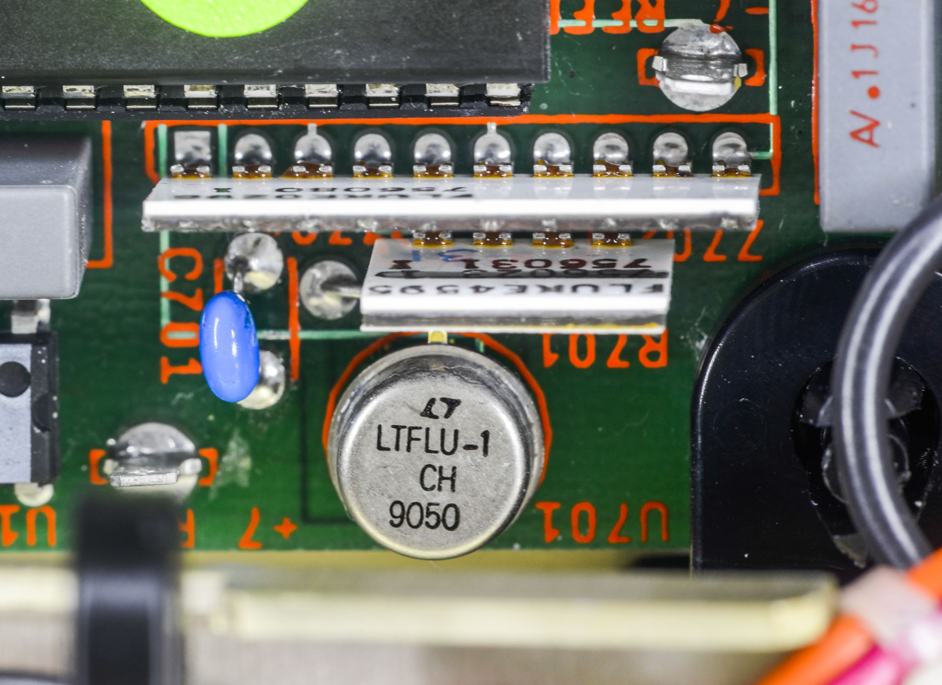
LTFLU-1 reference from Linear (now ADI) and Fluke hermetical resistor networks in 8842A DMM
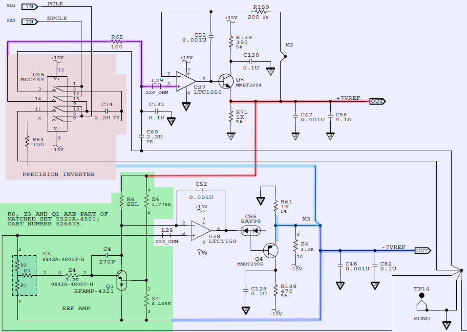
Fluke 57LFC calibrator using same reference REFAMP and resistor networks Z3,Z4
So it’s a special part, that nobody can buy from Digikey. Yes, however, there are reference modules around SZA263/LTFLU and voltage reference chips available from time to time on secondary market. Even though nobody can say for sure if they are fakes or genuine parts, sort out with bad specification or gray market production.
The specimen investigated here were sourced from Walton Electronics from Alibaba.
A tear-down of both parts revealed, that SZA263 is a two chip construction in one TO-package with separate silicon and zener diode, while LTFLU is a one chip design, both connected as a REFAMP with collector, base, emitter of the zener and anode of the silicon diode.
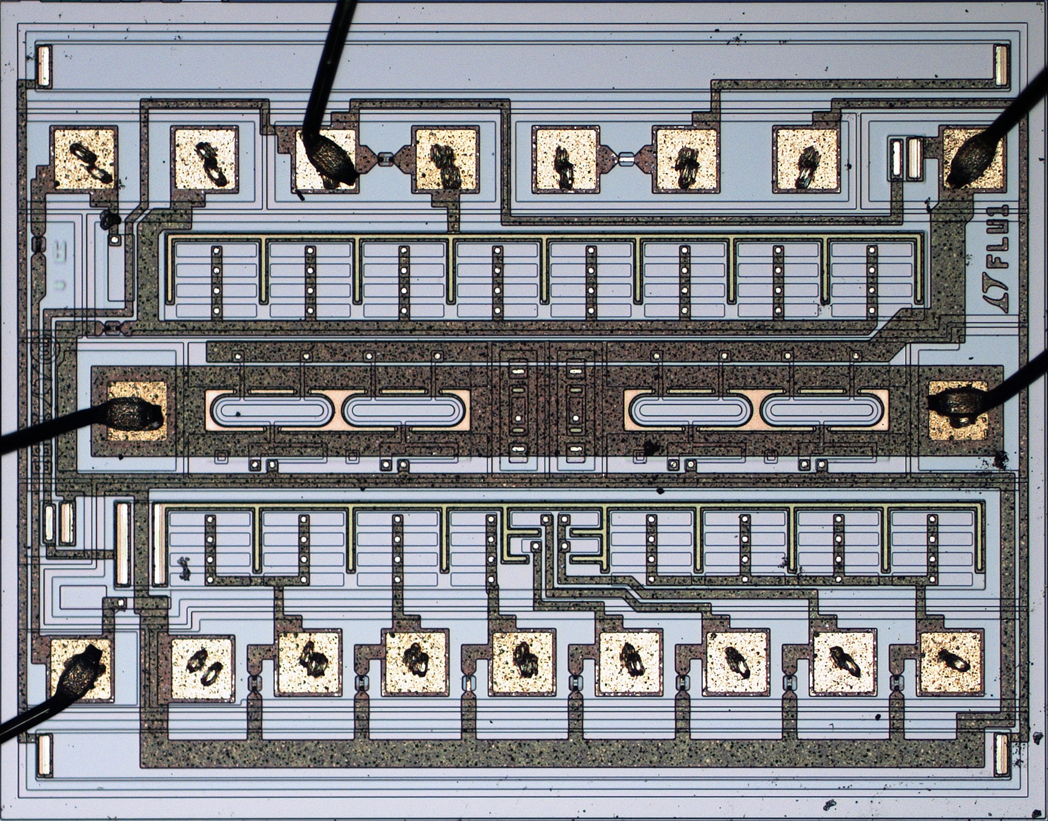
LTFLU-1CH die photo. Courtesy branadic (Dipl.-Ing. A. Bülau) from the EEVBlog
On the die photo we can see much more complex design than just diode and transistor. Different to Linear LTZ1000 which needs a separate stage to boost the zener voltage to 10V, the boost of the output on these REFAMPs is part of the zener circuit itself, realized in a bootstrap fashion. However, a 10V output requires an individually trimmed voltage divider for each device from the output to the base of the REFAMP. As found earlier the TC(Thermal Coefficient) of this divider is rather critical, as it is only dampened by a factor of ~3, while all other resistors of the circuit are less critical and their TC(Thermal Coefficient) is dampened by a factor of 150 … 500.
The typical zener current is IZ=3mA, with the zener voltage varying between VC = 6.8 … 7 V. Operation of this REFAMP-based voltage reference without an oven but somewhat optimized value for R13 can lead to a temperature behavior of less than 1 ppm/°C over 10..45°C, with a parabolic shape of the TC(Thermal coefficient) curve. However, for best performance the REFAMP should be ovenized to achieve 0ppm/°C. To set the zero TC(Thermal coefficient) for a given temperature the value of R13 needs to be determined, while the range for the current through it is IC = 20 … 200 µA.
This article addresses the findings so far, even though no datasheet is available. Fortunately, circuit diagrams of a lot of Fluke gear can be found using these refamps, which gives a starting point.
Circuit design and theory of operation
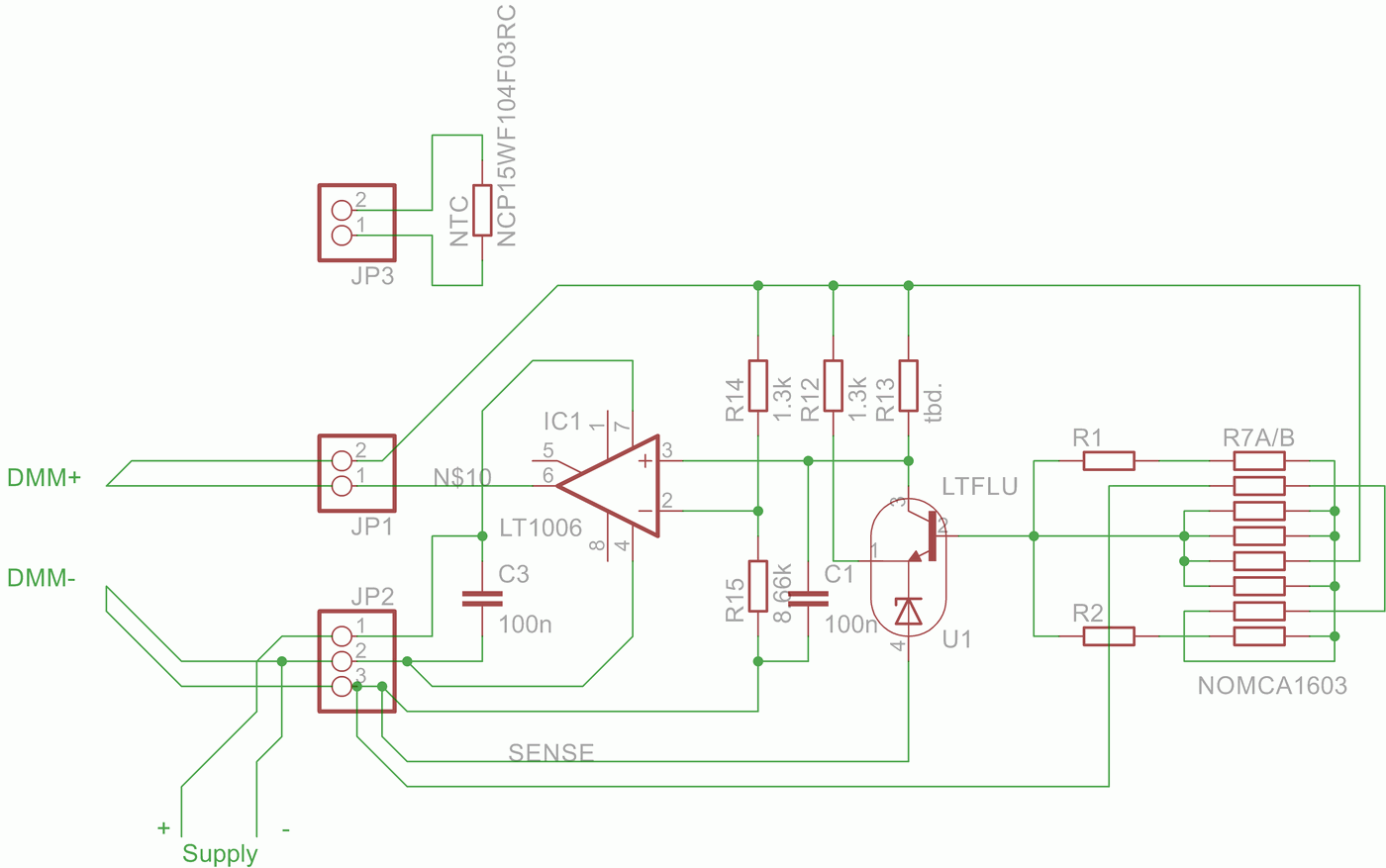
Figure 1: LTFLU/SZA263 module circuit
The goal is to build a battery powered, ovenized single supply 10V voltage reference based on LTFLU1-CH, similar to LTZ1047B designed by Andreas Jahn, a LTZ1000 based portable voltage reference. The oven is planed to use a ceramic or aluminum core substrate mounted on a thick-film resistor.
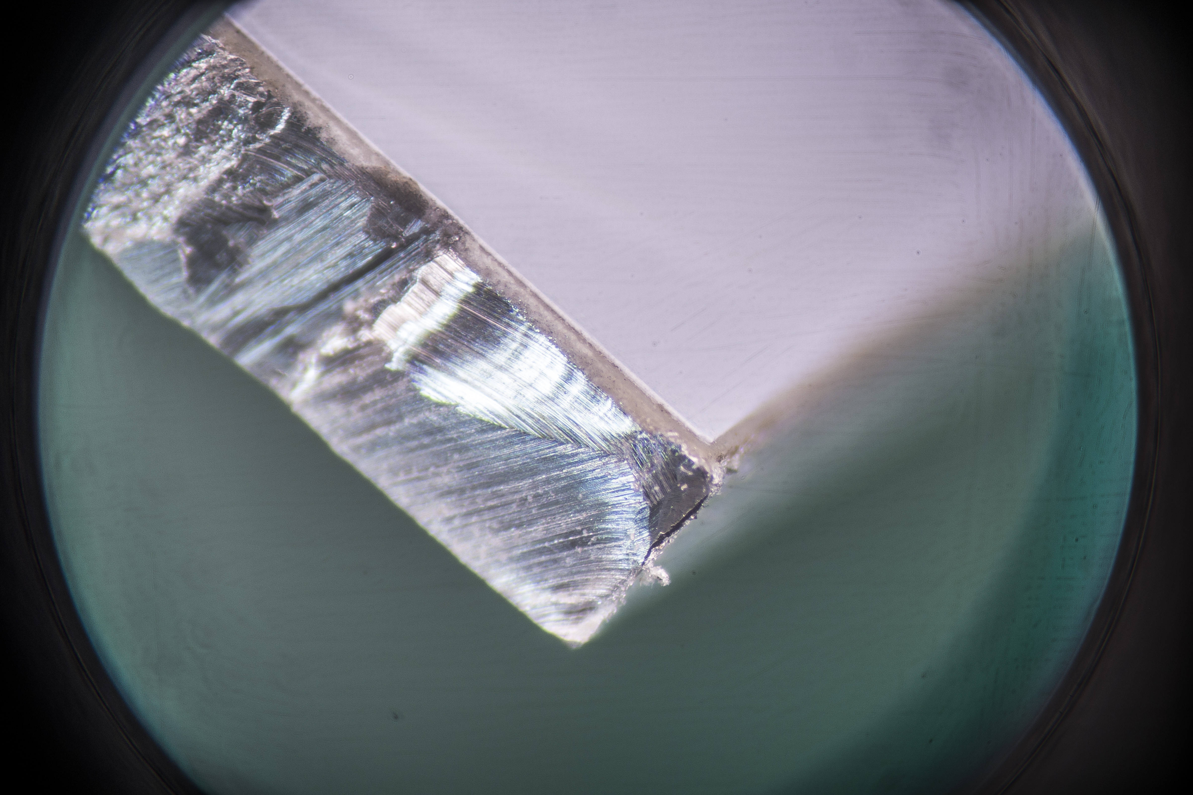
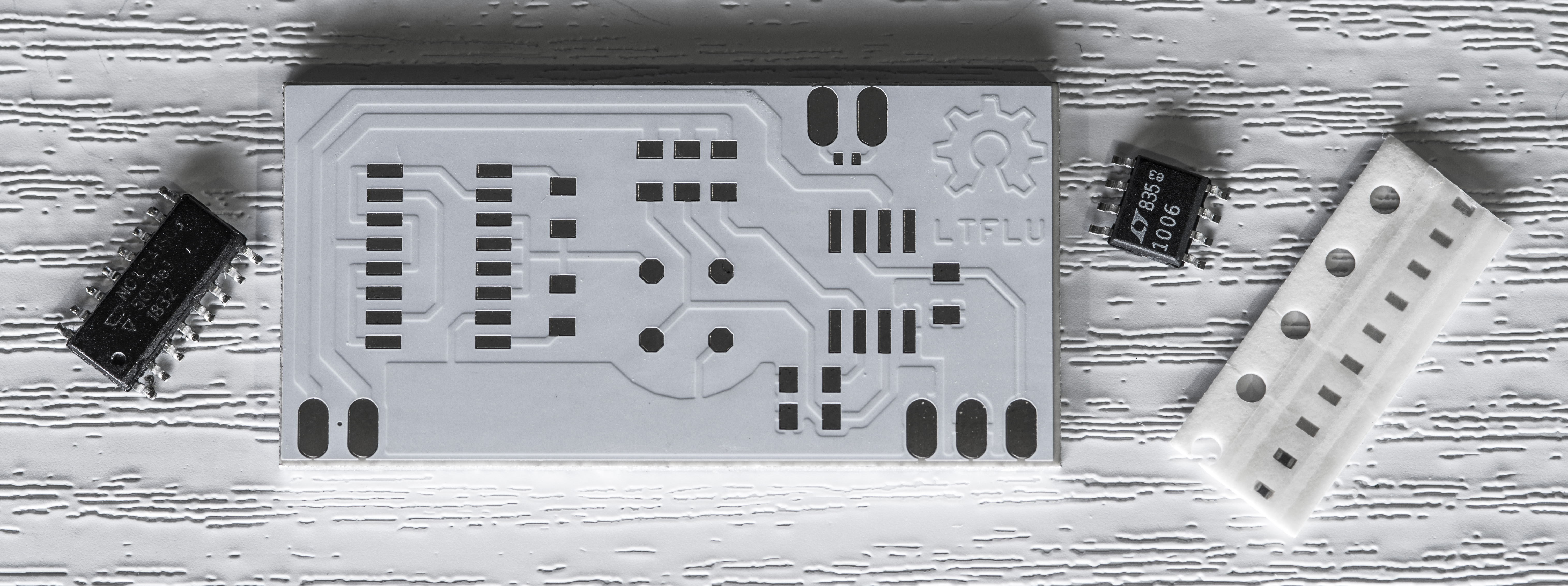
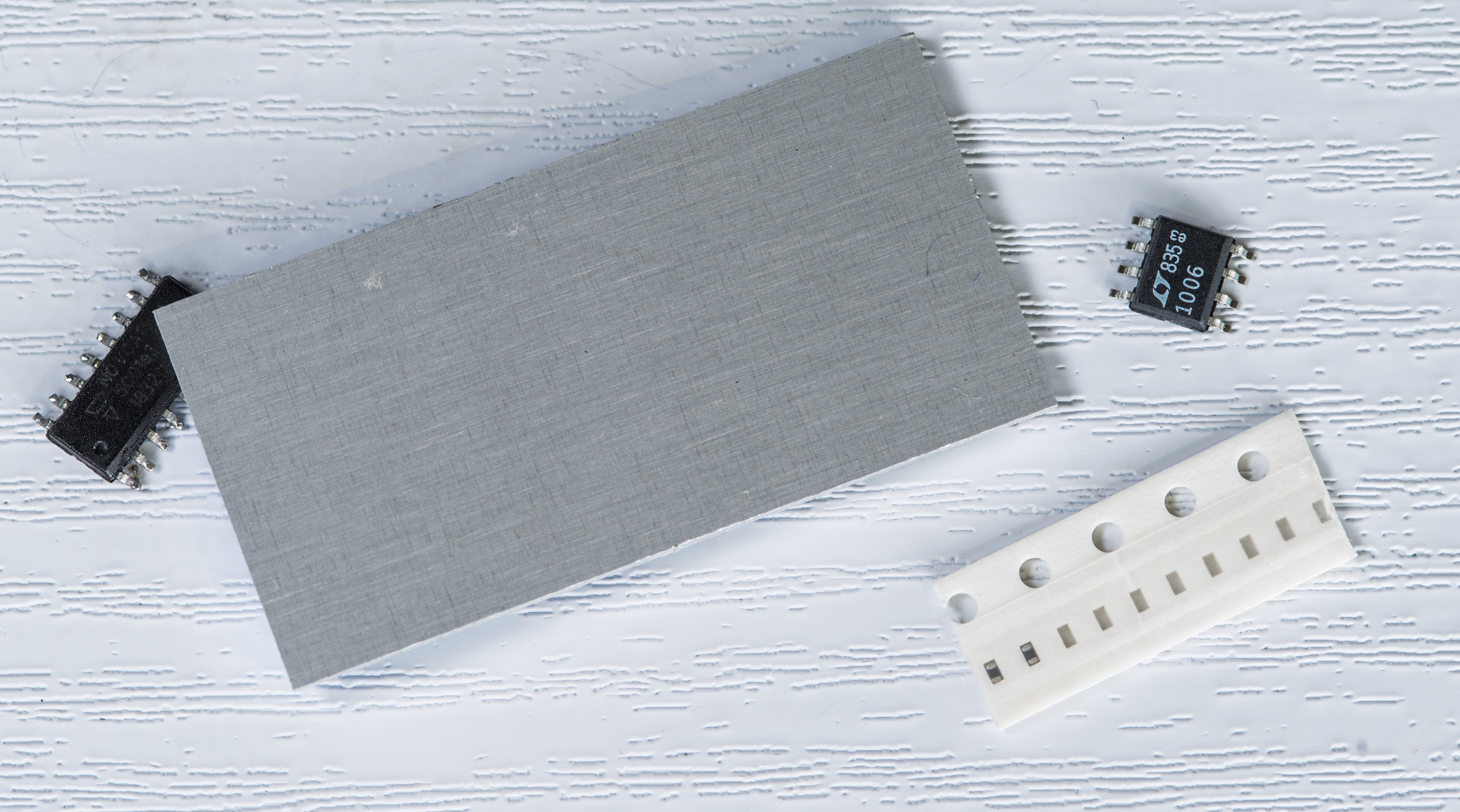
Figure 2: Aluminum substrate PCB, shows very thin layer of dielectric embedded to metal
Pre-regulation shall be done by LDO LT1763 supplied by a battery pack of 12× 1,2V Eneloop, a total of 14,4V. Based on circuits available a schematic as shown in Figure 1 was designed. Therefore a single supply op-amp LT1006 (or OPA189, ADA4522-1) comes into play. As for the critical resistor divider R7A/B a NOMCA16035001 is used with additional resistors (R1 and R2) being integrated into the divider to trim the output voltage to 10.00000V and to reduce their influence.
The oven temperature is planed to be +45…+50 °C, which should be enough headroom even in summer. A NTC mounted to the reference board serves as a temperature sensor for the oven. NCP15 series by Murata is said to have good long-term stability, thus it is used here. Zero TC(Thermal Coefficient) temperature has to be found within the desired temperature range by adjusting R13 value respectively. To do so a breadboard was used with R7A/B pretrimmed for a nominal 10V output voltage by arranging the NOMCA resistor network to R7A = 5 kΩ and R7B = 11 kΩ. This is necessary, as the output voltage also influences the current through a given R13.
Measurements of temperature profile inside a temperature chamber while varying R13 with a decade resistor box gave the following values for the zero TC(Thermal Coefficient) temperature:
| R13 | 25.343 kΩ | ~30 °C |
| R13 | 24 kΩ | ~35 °C |
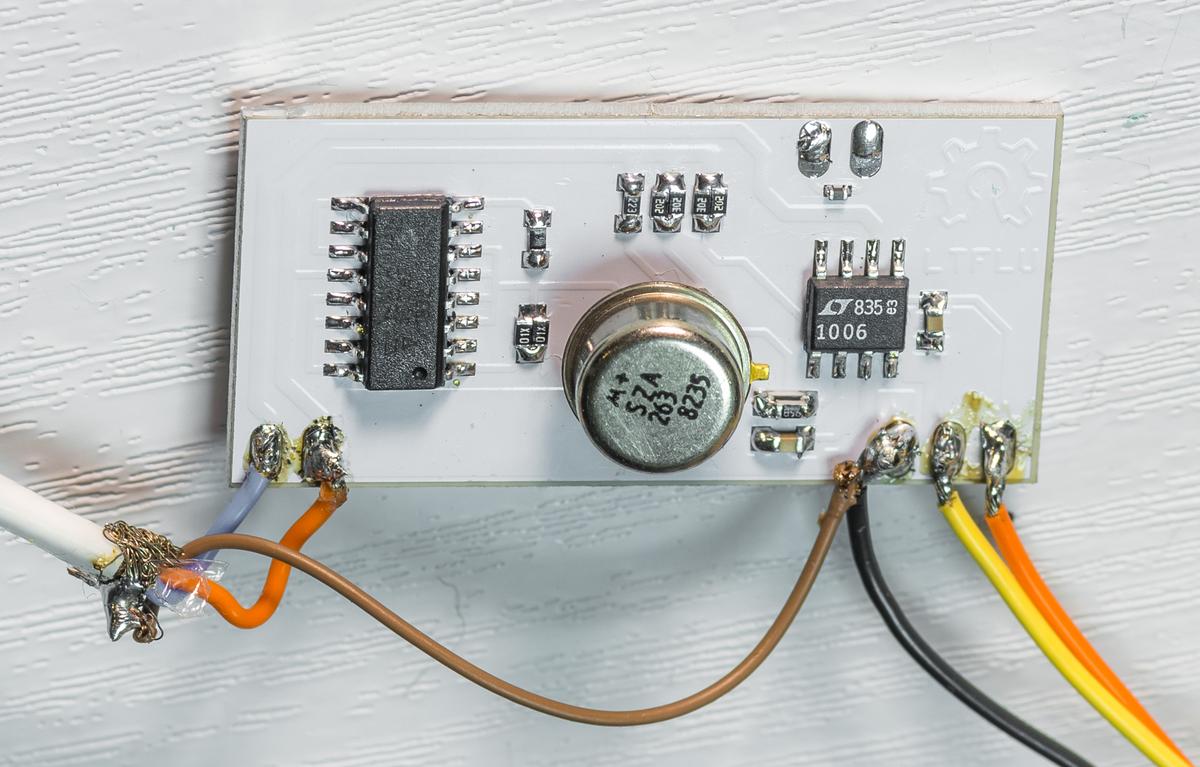
Zero TC(Thermal Coefficient) point is the middle highest point of the flipped parabolic shaped curve, when plotting output voltage over temperature. Assuming a linear correlation between IC and zero TC(Thermal Coefficient) temperature point a value of about 22kΩ for a temperature setpoint of 45°C can be calculated. A repeated temperature profile well agreed with the assumptions, the zero TC(Thermal Coefficient) point is well within 45 … 50°C. Based on this results a reference board was designed as shown in Figure2. It‘s 20 × 40 mm2 in size. The LTFLU is soldered in a SMT style to the board and the output is realized as a 4 wire connection.
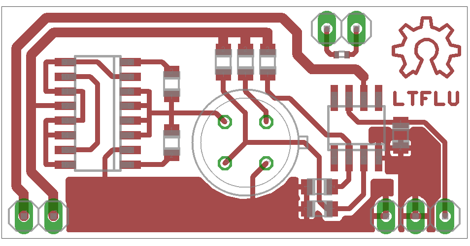
Figure 3: LTFLU reference board
Typical resistor values used for one of the first modules are shown on Figure 4 for reference.
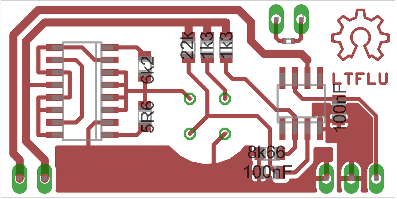
Figure 4: Components values for first module
Several temperature profiles were performed with R13 = 22 kΩ and by varying the additional resistors R1 and R2, giving the following results.
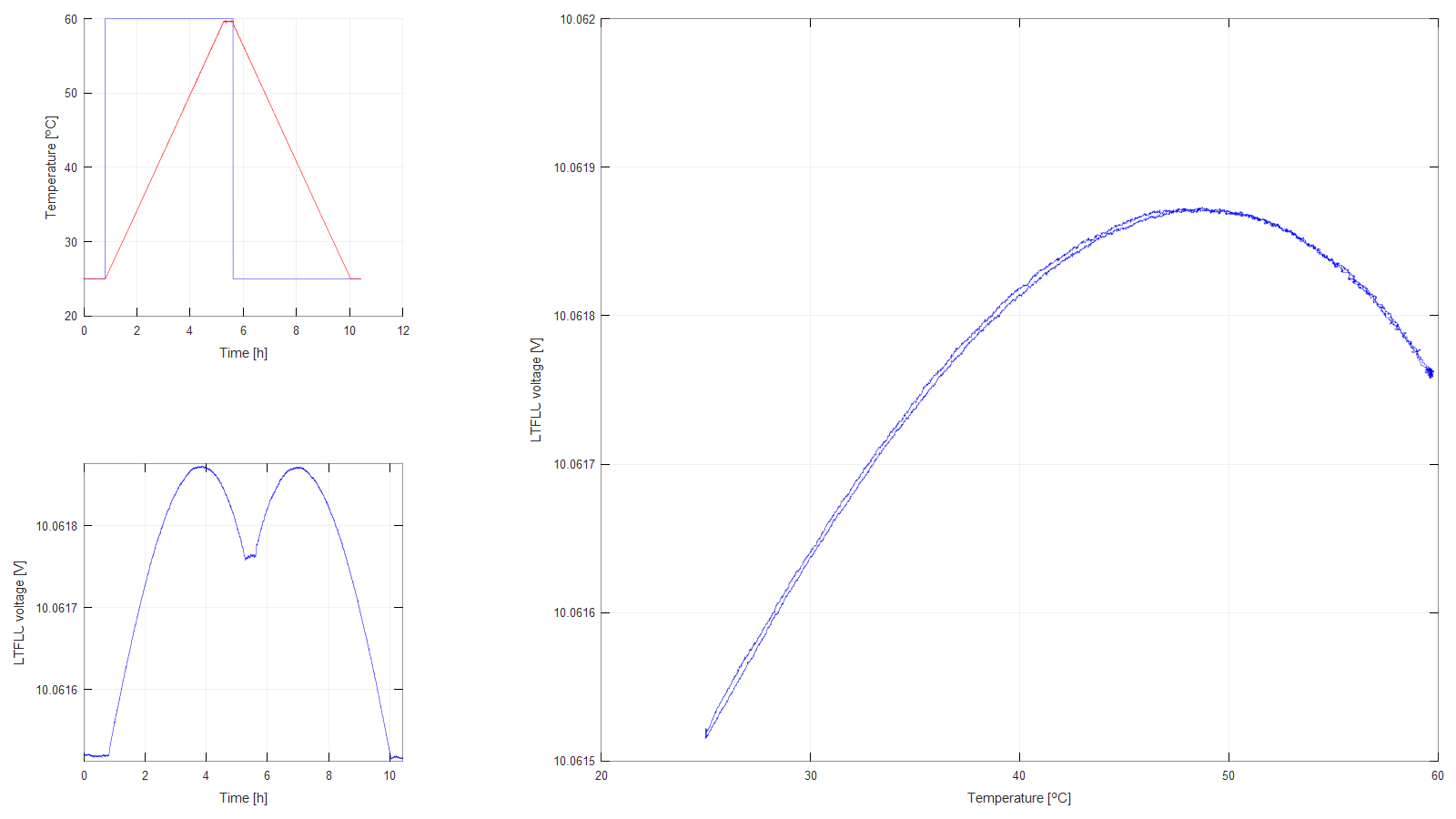
Figure 5: LTFLU Temperature profile 1
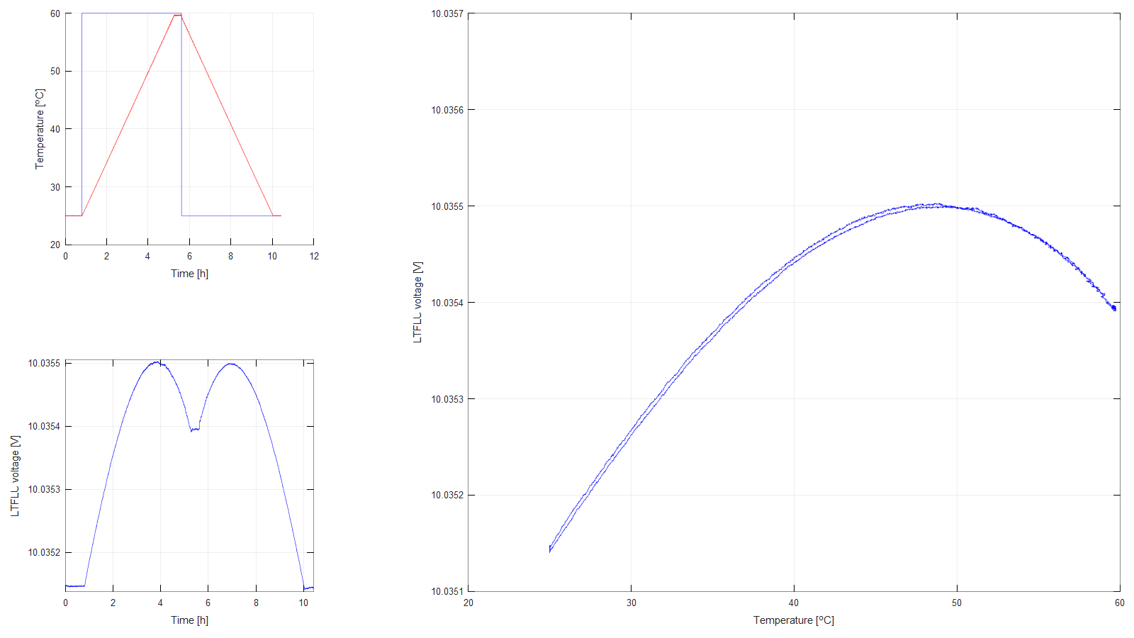
Figure 6: Temperature profile 2
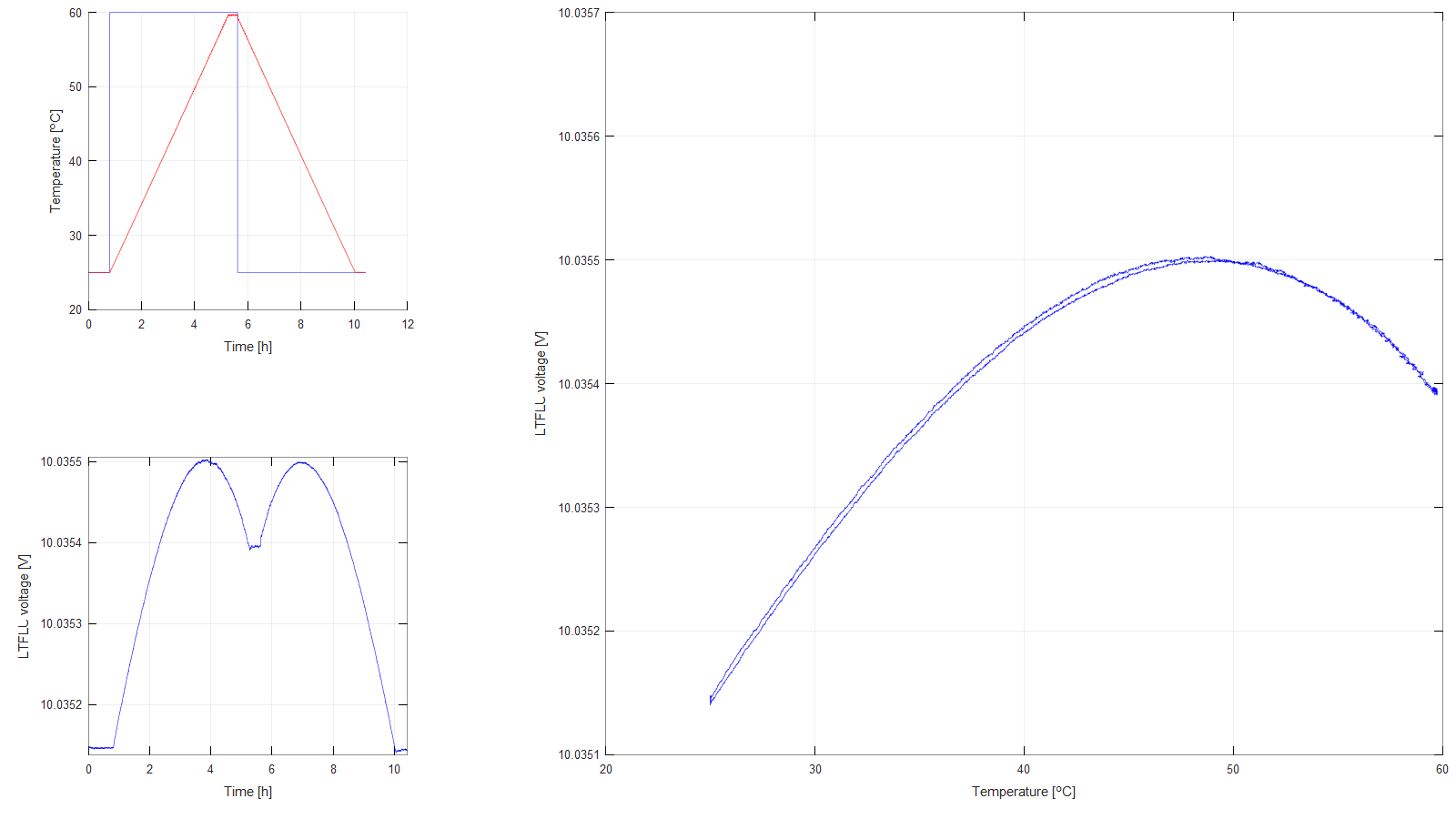
Figure 7: Temperature profile 3
| Profile 1 | Profile 2 | Profile 3 | |
| R7A | 5 kΩ | 5k Ω | 5 kΩ |
| R7B | 10.9091 kΩ | 11 kΩ | 11.0651 kΩ |
| Ratio | 0.4583 | 0.4545 | 0.4519 |
| Voltage @ zero TC(Thermal Coefficient) | 10.061870 V | 10.035500 V | 10.016960 V |
With the values given one can calculate the required ratio of 0.4494 as well as the required resistors to trim the output to 10.00000V. It turns out that for this specimen R1 = 6.2 kΩ trims the output to the required range, while R2 = 0…10 Ω adjusts the output to the final value.
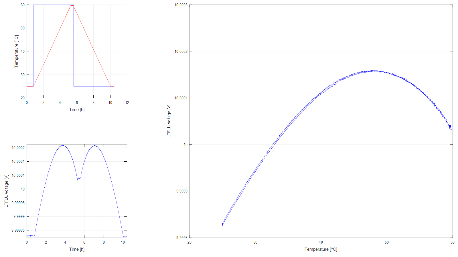
Figure 8: Temperature profile 4
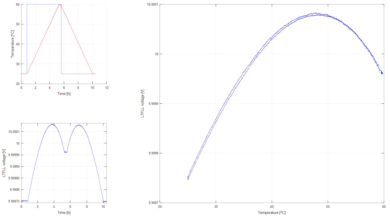
Figure 9: Temperature profile 5
Up to this point all the measurements were performed with the aluminum board in a temperature controlled incubator and the temperature sensor used is the one inside the thermal chamber itself, with an Arroyo 5305 temperature controller.
For the final application the aluminum board with the reference circuit and a 10 kΩ NTC type NCP15XH103F03RC with a Beta = 3380 K is assembled with a thickfilm resistor BPR10J101 attached to its back. The whole assembly is located inside a styrofoam box and lined with wadding.
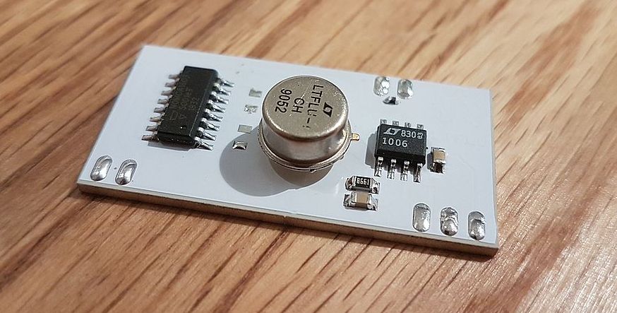
Figure 10: Assembled LTFLU reference with NOMCA network
First a W1209 2-point controller was used to stabilize the oven temperature, which is powered by 12 V and uses a 10 kΩ NTCs. It can be set to the required oven temperature with a resolution of 0.1 °C. It turned out to create large temperature gradients on the aluminum board and the reference, that resulted in voltage readings with large switching noise. Thus, the idea was discarded and a linear temperature controller approach got in focus.
The resistance over temperature and Beta of the NTC are given in the corresponding datasheet. This values were translated into coefficients for the Steinhart-Hart equation using an this online calculator and fed into the Arroyo 5305 TEC controller. TEC controller configured to heat only mode with output voltages of up to 12 VDC.
First of all the controller and its autotune function was used to find the optimum PID parameters. Second, a temperature sweep was performed to find the temperature of the oven, at which the temperature coefficient of the voltage reference is zero. It turned out, that the sweet spot was at +47.844 °C.
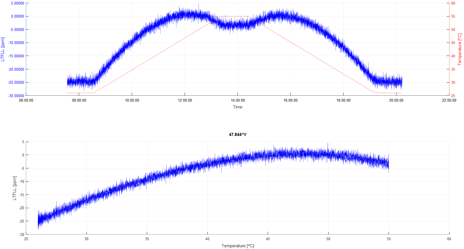
Figure 11: Temperature profie of the oven assembly with Arroyo 5305
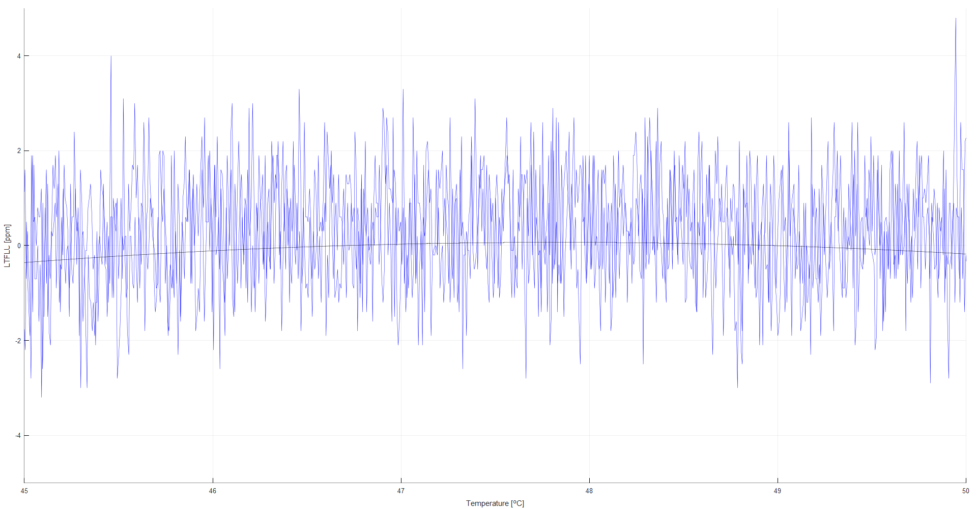
Figure 12: Zoomed in area over a range of ±5 °C output deviation observed less than 0.3 ppm
A temperature around +48 °C appears to be a good choice. Furthermore, the output voltage of the controller at this temperature was determined to be about 7.6 V.
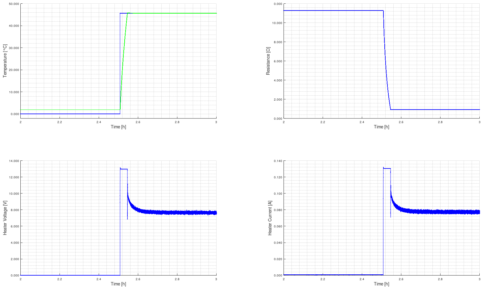
Figure 13: Temperature jump to ztc temperature setpoint
To derive the impulse response of the oven assembly alone aka of the open loop a voltage jump from 0V to 7.6 V across the heater resistor was performed using a lab power supply, while the controller was used to sample the NTC resistance as well as the calculated temperature.
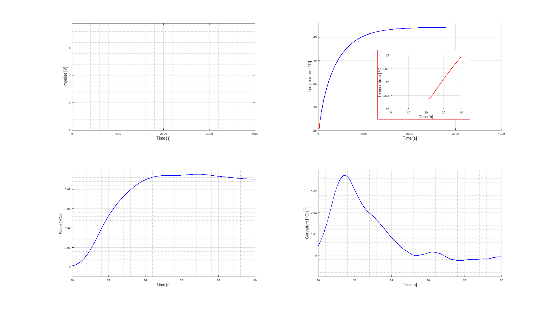
Figure 13: Open loop impulse response of the oven
As shown, the oven assembly acts as a PT2 term. From the second derivative of the measured oven temperature the inflection point can be derived and the slope in this point from the first derivative. From there the tangent of inflection and both the dead time Tu and the compensation time Tg were calculated. This calculation was performed in GNU Octave using the diff command.
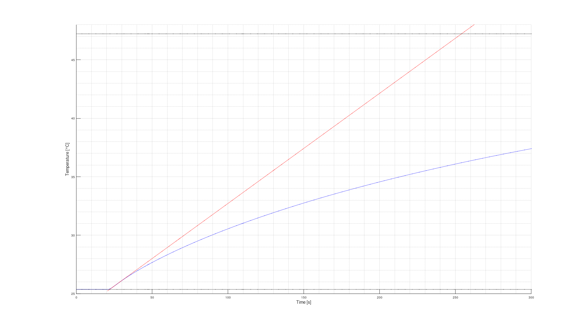
Figure 14: Determination of tangent of inflection and time constants
This math revealed inflection point at t = 4.753 s, slope m = 0.094185 °C/s and Tu = 1.494 s , Tg = 232.0457 s. Let’s call its Tu = 1.5 s and Tg = 232 s with a controllability Tg/Tu = 155. A controllability of over 10 is good and achieved.
From here KS cn be calculated. Reference material for further study available here (DE).
KS = (47.22327 °C – 25.36802 °C) / 7.6 V = 2.87569 °C/V.
The oven draws about 73 mA at 7.6V, which is 550 mW.
Now that the behavior of the oven is well known the controller can be designed. It was decided to use a PI controller. With the help of H. Walter and the control_theory1.lib by Helmut S .
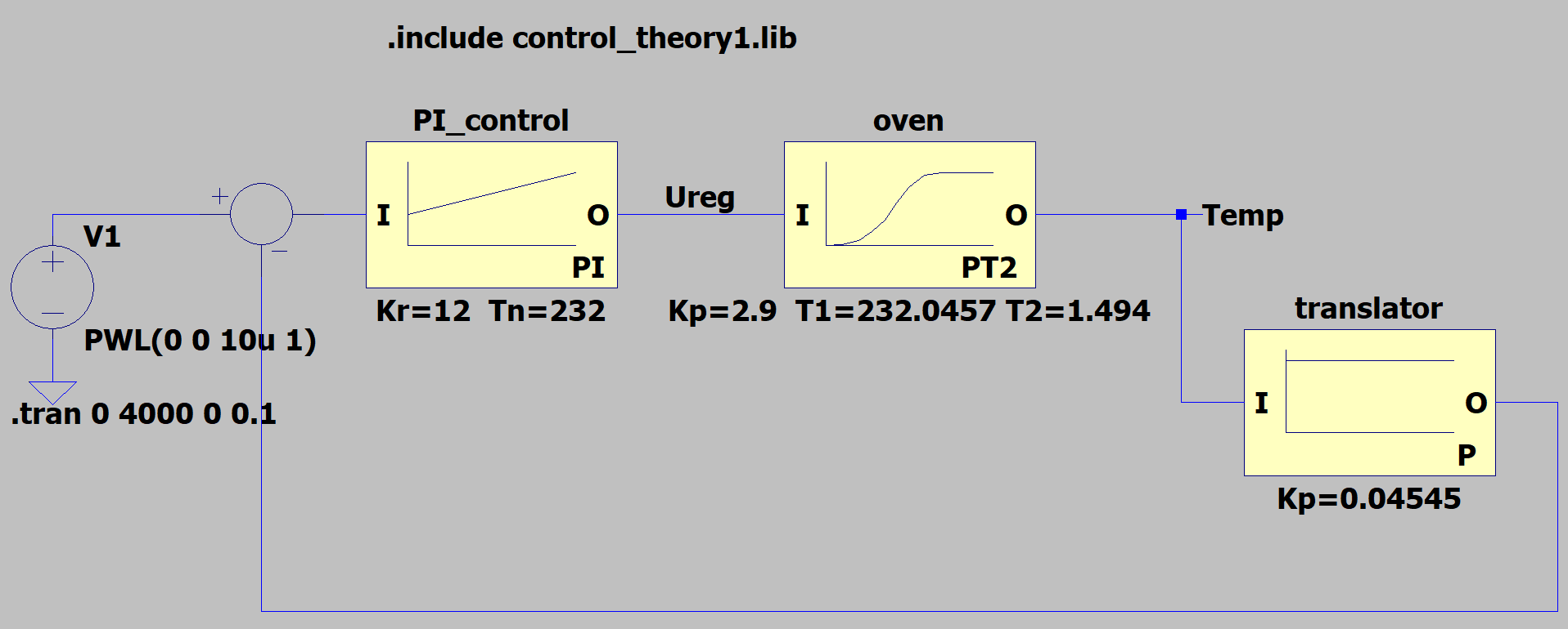
Figure 15: Simulation model as a block diagram in LTSpice
The block diagram was then translated into an analog circuit and again build in LTspice, including the PI controller as well as a target delay to play with, the oven response as a PT2 term and the coupling with the NTC temperature sensor. The circuit was designed to use a single +12 V power rail for reference and oven only, thus an AD822 was used.
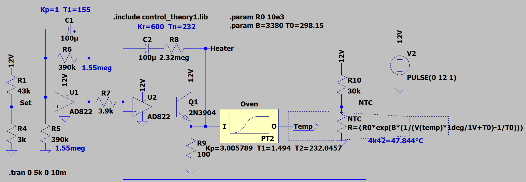
Figure 16: Simulation model of analog temperature controller in LTSpice
LTSpice analog controller project file
The simulation results prove, that a temperature of +47.59 °C should be reached, using standard resistor values without further adjustment, which is close enough to the optimum zero t.c. point of +47.844 °C
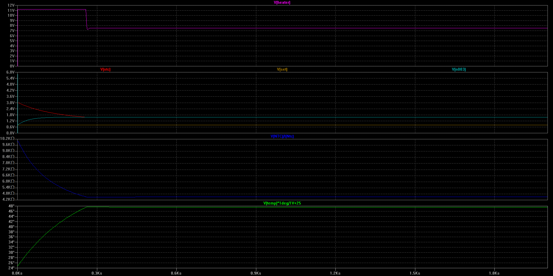
Figure 17: Simulation results from LTSpice
Based on this a perfboard for the oven was hacked together and tested for stability.
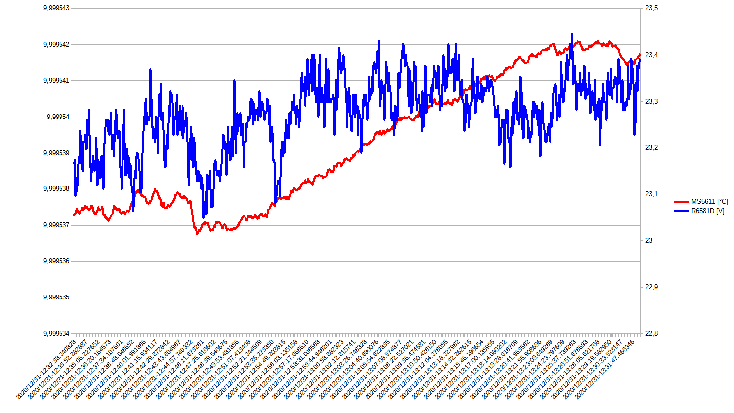
Figure 18: Actual measurement results for stability
It was found, that the reference is rather noisy (refer to 1h stability measurement in the figure above). Since it wasn’t clear if this is limited by the noise of the NOMCA16035001 network or the reference itself, a new revision with TOMC16031002 network was designed.
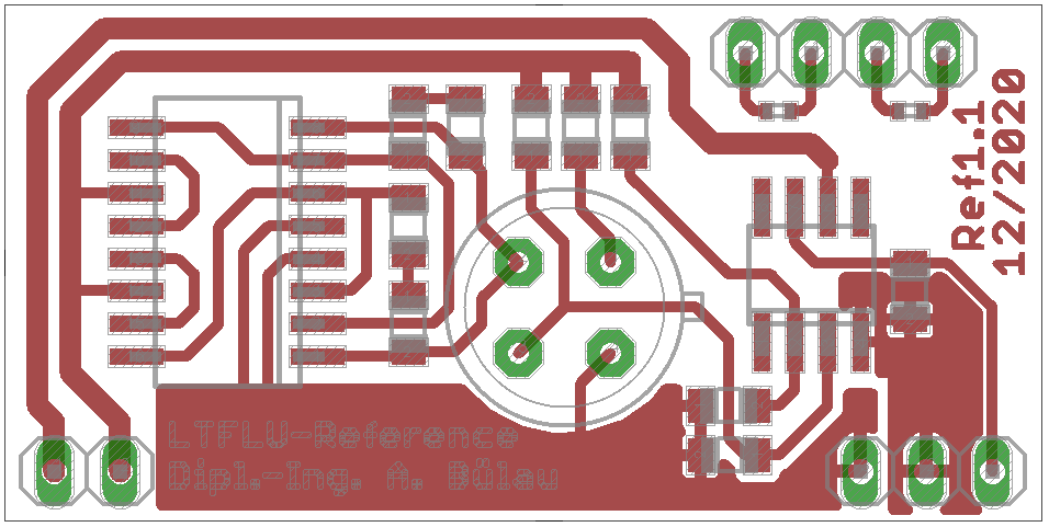
Figure 19: New PCB layout for TOMC network
This network series was chosen from “preliminary numbers provided by Nikolai Beev. He tested several resistor networks series noise index.
- NOMCA : 5 kΩ -24.9 dB; 10 kΩ -29.5 dB;
- TOMC : 10 kΩ -52.1 dB;
As well as own measurement indicated lower noise, more than a factor of 10, from TOMC is to be expected.
Unfortunately TOMC comes in a slightly different package than NOMCA, medium SOIC16 instead of narrow SOIC16 and wasn’t available in a 5kΩ version but 10kΩ instead, so it couldn’t be used as a drop-in replacement.
The modified circuit thus has a slightly different resistor arrangement. Furthermore, the network has a different connection scheme to allow trimming either the upper or the lower part of the network. This way references with different output voltages can be adjusted to 10V. A second NTC was added, to allow observing oven stability with an external measurement device.
The LTFLU reference and other components were transplanted to the new board and the trimming resistors were assembled with shorts in the first place
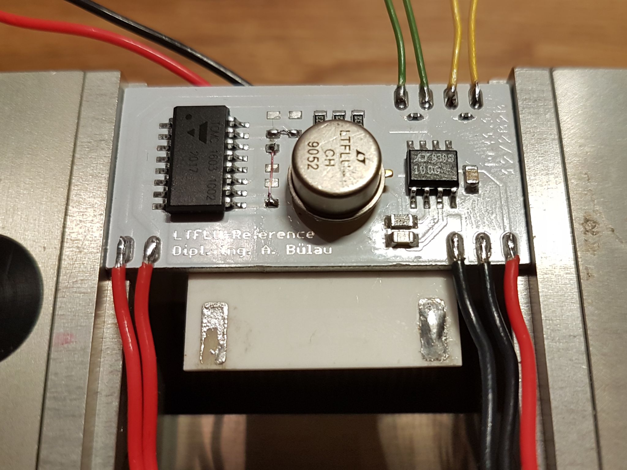
Figure 20: New PCBA assembly with TOMC network
The board was then put back into its styrofoam box and connected to the TEC controller. Starting with the former found PID parameters a new autotune was performed using the first onboard NTC. It turned out that with the new board the parameters slightly changed from:
P=0.4760, I=0.0012, D=4.1801 to P=0.4716103, I=0.0012545, D=3.2423208
With this parameter another temperature sweep from +25 to +60 °C and back was performed to test how zero t.c. temperature point changed. The second onboard NTC was monitored with a meter in parallel. The z.t.c. temperature was found at around +54.5 °C, due to the higher output voltage of 10.35 V.
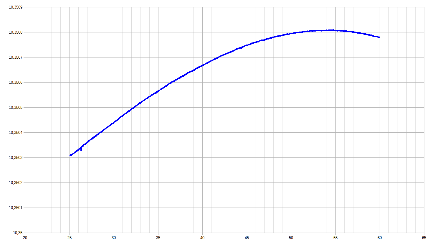
Figure 21: Temperature sweep
Next, stability at z.t.c. temperature was tested. The figure below shows the 1h stability. Compared to former stability measurement with NOMCA network, noise has somewhat improved, but still wasn’t satisfying
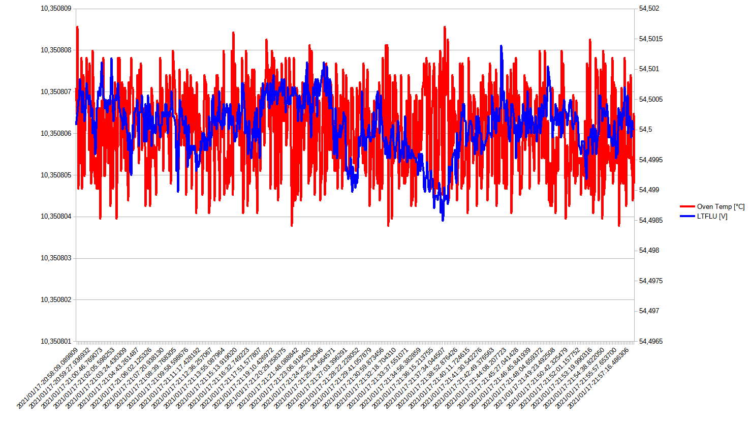
Figure 22: Voltage measurements
The ouput voltage was then trimmed using a General Radio 1434-G decade resistors. Since this trimming changes the output voltage also the current IC will change so does the z.t.c. temperature. Thus, another temperature sweep was performed and z.t.c. was found at about +45.5 °C with the output voltage being about 20 ppm above 10V. Both, trimming and finding the new z.t.c. temperature go hand in hand with each other, but the closer one gets to the final value for the output voltage and the smaller it changes, the smaller the effects on the z.t.c. temperature.
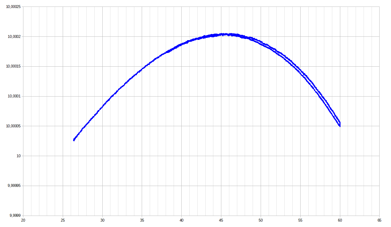
Figure 19: Trimmed temperature sweep
During the experiments it was observed, that leaving the aluminum board floating resulted in all sorts of disturbance of the reference output voltage and spikes by interference due to an unknown external source, that fully vanished, once the aluminum was tied to ground.
A measurement of the stability over a few hours shows, that noise is now more in the order of a conventional low noise reference such as LTZ1000 but still slightly higher. Use of better TOMC network improved things significantly.
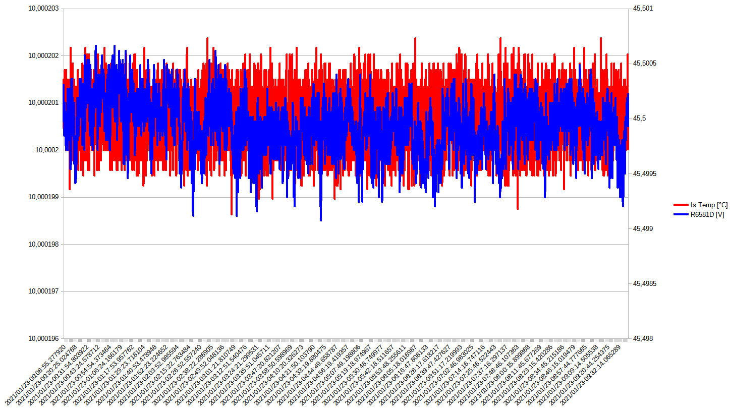
Figure 19: Measurements with trimmed assembly
Next step is to adjust the discrete oven to the new temperature and repeat measurements (stability, noise etc.).
To be continued …
Building one of the test modules in xDevs US lab for testing
Recently Illya have received and assembled one test module during livestream recording, showing process and steps involved.
And photograph of assembled module with cheap test resistors:
Next step would be trimming for precise 10V output, fine-tuning temperature stability and doing noise performance tests and measurements.
Projects like this are born from passion and a desire to share how things work. Education is the foundation of a healthy society - especially important in today's volatile world. xDevs began as a personal project notepad in Kherson, Ukraine back in 2008 and has grown with support of passionate readers just like you. There are no (and never will be) any ads, sponsors or shareholders behind xDevs.com, just a commitment to inspire and help learning. If you are in a position to help others like us, please consider supporting xDevs.com’s home-country Ukraine in its defense of freedom to speak, freedom to live in peace and freedom to choose their way. You can use official site to support Ukraine – United24 or Help99. Every cent counts.
Modified: Jan. 30, 2021, 10:50 p.m.