Contents
- Intro
- Disclaimer
- Project goal
- Reference circuit
- Temperature control circuit
- Schematic design
- Layout design
- Assembly notes
- Initial data results
- Thermal analysis
- Test chamber design
- Temperature coefficient measurements and analysis
- Performance verification
Intro
MX magic write-up goes here..
Disclaimer
Redistribution and use of this article or any images or files referenced in it, in source and binary forms, with or without modification, are permitted provided that the following conditions are met:
- Redistribution of article must retain the above copyright notice, this list of conditions, link to this page (/article/kx-ref/) and the following disclaimer.
- Redistribution of files in binary form must reproduce the above copyright notice, this list of conditions, link to this page (/article/kx-ref/), and the following disclaimer in the documentation and/or other materials provided with the distribution, for example Readme file.
All information posted here is hosted just for education purposes and provided AS IS. In no event shall the author, xDevs.com site, or any other 3rd party, be liable for any special, direct, indirect, or consequential damages or any damages whatsoever resulting from loss of use, data or profits, whether in an action of contract, negligence or other tortuous action, arising out of or in connection with the use or performance of information published here.
Project goal and specifications
- Maximum stability for DC voltage reference
- Low tempco precision wire-wound resistors, PCB for both PWW Ultrohm Plus and Vishay VPG resistors.
- Linear LTZ1000 ultrazener [4]
- Thermal sensor NTC for external calibration purpose
- Compact 80 × 120 mm form factor to fix Hammond metal enclosure
- 1ppm/year voltage output
- 7.15VDC ±1% direct output
- Thermostat setpoint +55°C
- Kelvin sense output
- Single-rail voltage input
- 2.54mm SIP connection ports
- PCB space for add-on board to use direct output from LTZ1000
- Basic reverse supply voltage protection.
- Room for 3D printed cap on top and bottom of board for LTZ
- Room for 3D printed cover for rest of board.
| Item | Value | Units |
|---|---|---|
| Input voltage Vin, reference module | +18.0 | VDC |
| Output current, Reference output at VREF port | 1 | mADC |
| Operating temperature range | 0 to +50 | °C |
| Storage temperature range | 0 to +80 | °C |
| Lead temperature (soldering, 10s) | +240 | °C |
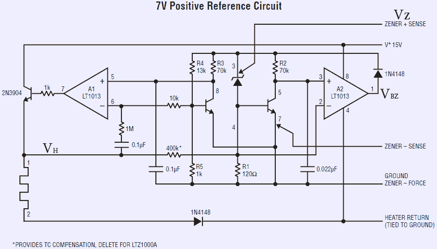
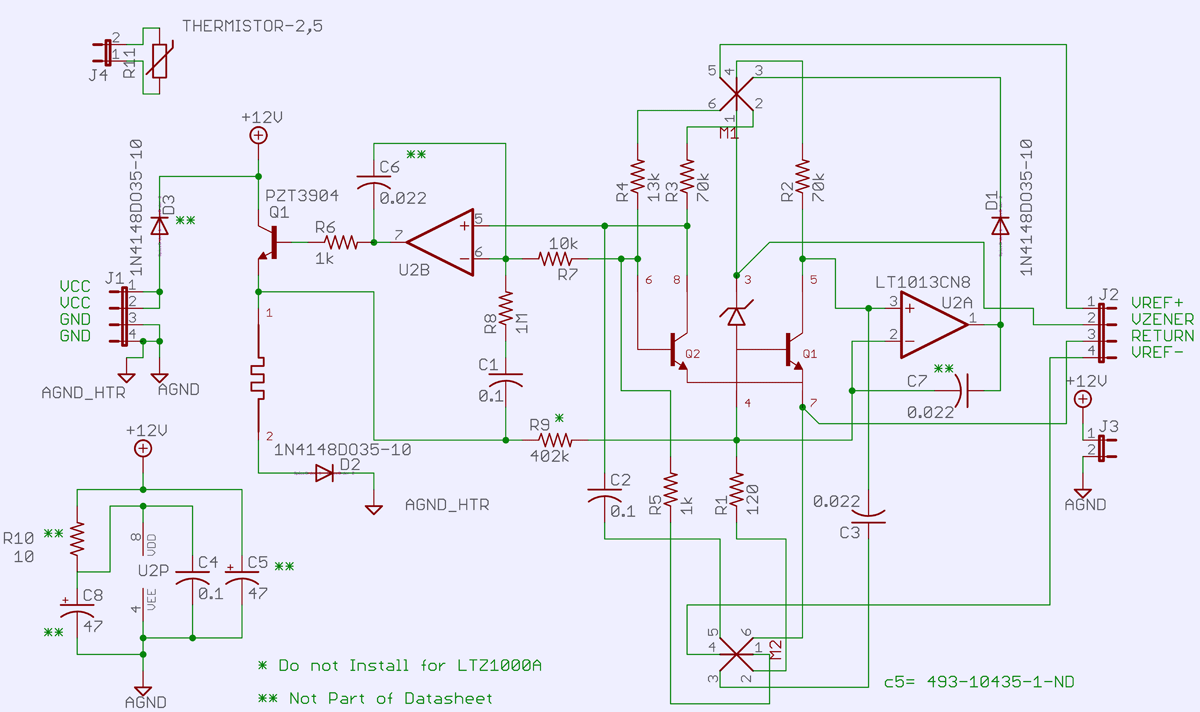
Schematics 1: Linear LTZ1000 reference design schematics (old-rev)
Now to stay on safe side, base reference circuit will repeat datasheet schematics with very minor changes.
Test ports definitions are as shown in tables below
| Board reference | Schematic signal name | Direction,type | Description |
|---|---|---|---|
| J1.1 | VCC | Input, power | Positive power input (+9 to +24VDC) |
| J1.2 | VCC | Input, power | Positive power input (+9 to +24VDC) |
| J1.3 | GND | Input, power | Power return |
| J1.4 | GND | Input, power | Power return |
Table 3: Port definition J1
And output of the reference available at J2 port.
| Board reference | Schematic signal name | Direction,type | Description |
|---|---|---|---|
| J2.1 | VREF+ | Output, sense | U1 LTZ1000 pin 3 sense output |
| J2.2 | VZENER | Output, drive | Zener reference drive output |
| J2.3 | RETURN | Output, drive | Signal ground return output |
| J2.4 | VREF- | Output, sense | U1 LTZ1000 pin 7 sense output |
Table 4: Port definition J2
| Board reference | Schematic signal name | Direction,type | Description |
|---|---|---|---|
| J3.1 | +12V | Power, +12V | Polarity protected power output |
| J3.2 | GND | Power, GND | Power ground return |
Table 4: Port definition J2
| Board reference | Schematic signal name | Direction,type | Description |
|---|---|---|---|
| J4.1 | NTC-A | Output, NTC | NTC resistor pin 1 |
| J4.2 | NTC-B | Output, NTC | NTC resistor pin 2 |
Table 4: Port definition J2
Layout design
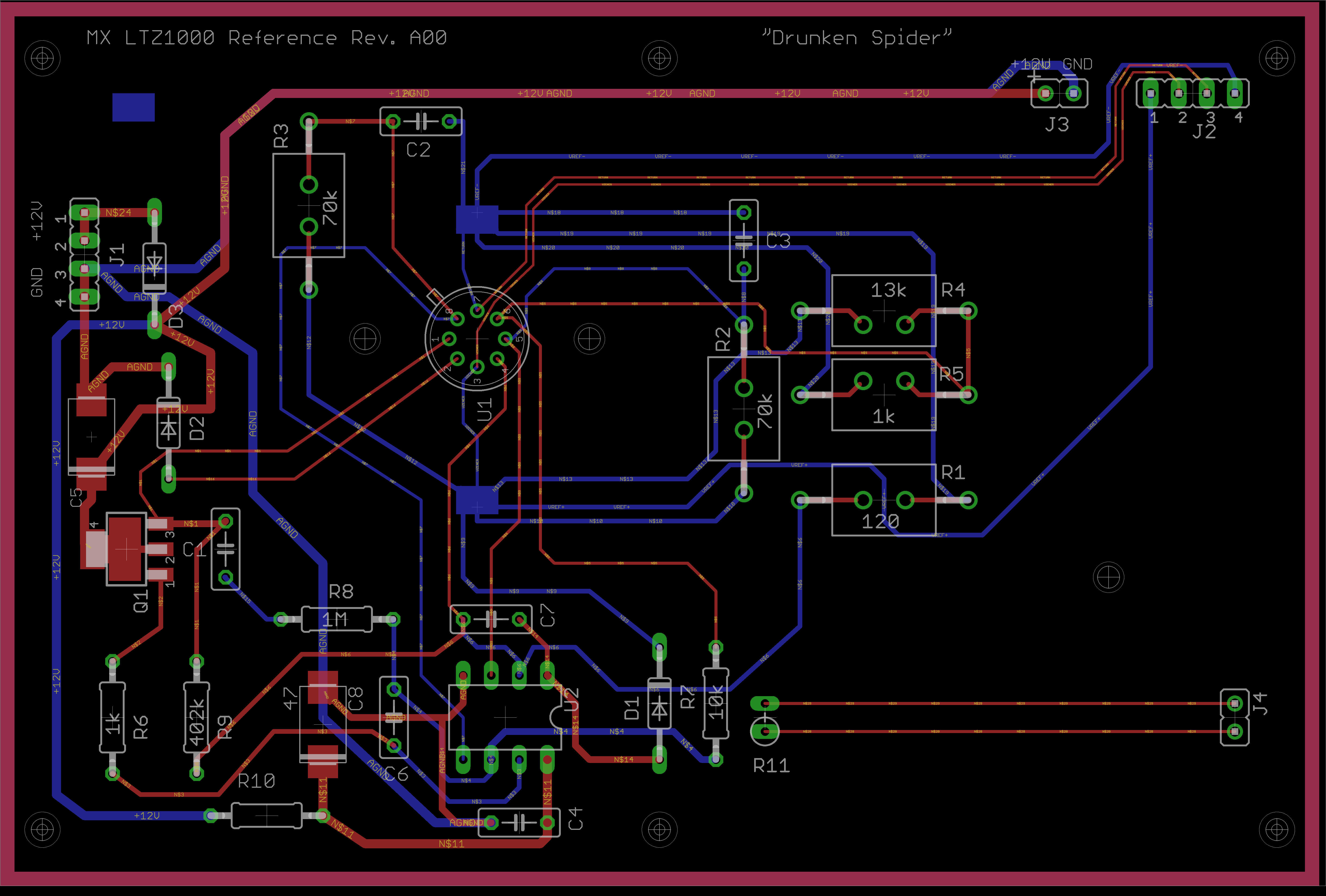
Image 3: xDevs.com MX voltage reference (Rev.A00) PCB cross-section
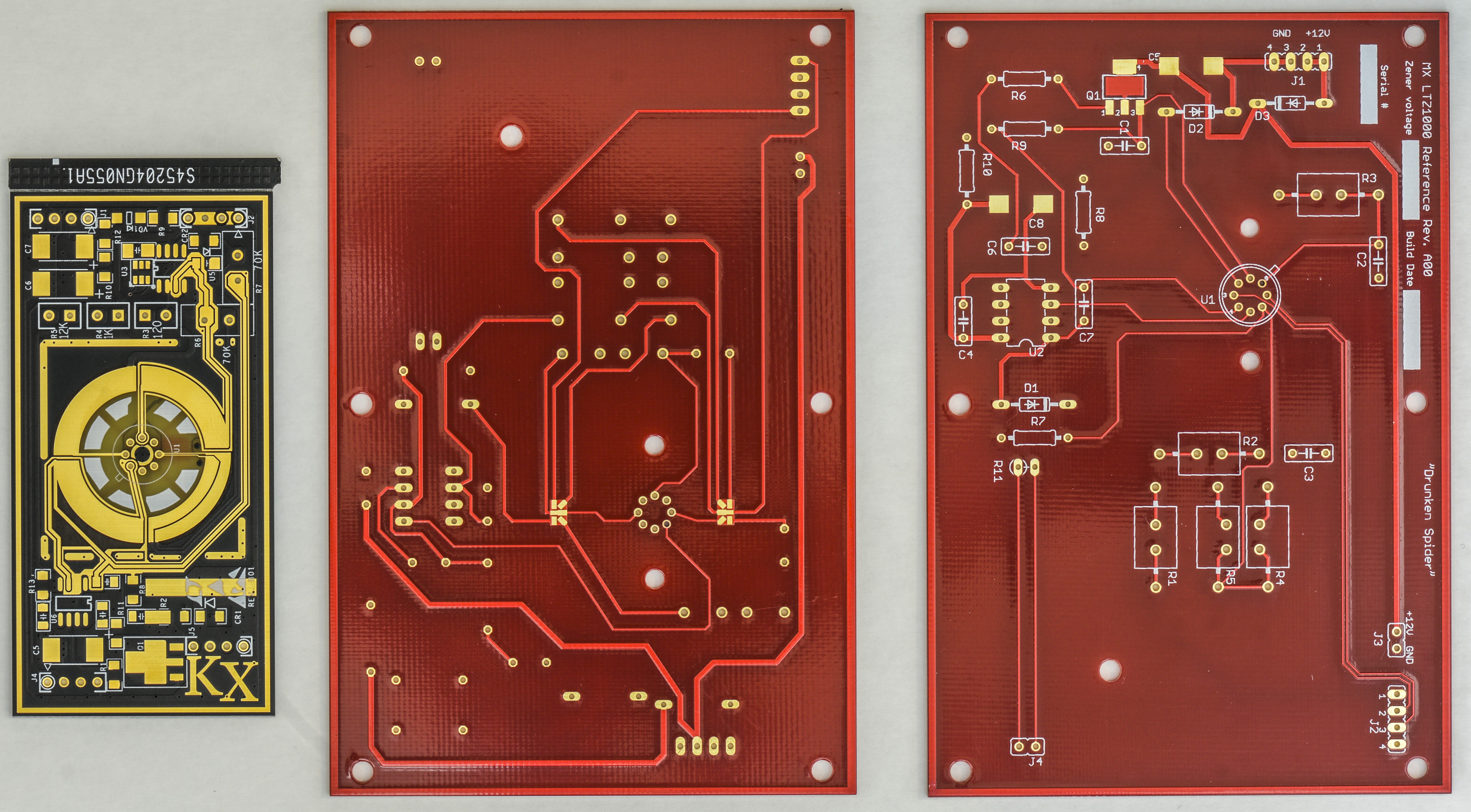
Image 3: xDevs.com MX voltage reference (Rev.A00) PCB cross-section
Assembly notes
Total BOM list of components used is listed in table.
| Digikey Part Number | Manufacturer | Manufacturer Part Number | Customer Ref Number | Customer Description | Quantity for module |
| N/A | Ultrohm Plus | N/A | R1-R5 | Custom made wirewound set | 1 |
| 495-2479-1-ND | EPCOS (TDK) | B32529C1104J289 | C1,C2,C4 | 0.1uF Cap Film 5% 100VDC | 3 |
| 495-2489-1-ND | EPCOS (TDK) | B32529C1223K289 | C3,C6,C7 | 22nF Cap Film 5% 100VDC | 3 |
| 399-3905-1-ND | KEMET | T495×476K035ATE300 | C5,C8 | 47uF Cap Tant. 10% 35V | 2 |
| 1N4148FS-ND | Fairchild/ON Semiconductor | 1N4148 | D1-D3 | 1N4148 Gen Purp DO35 | 3 |
| PZT3904CT-ND | Fairchild/ON Semiconductor | PZT3904 | Q1 | Transistor NPN | 1 |
| 1.00KXBK-ND | Yageo | MFR-25FBF52-1K | R6 | 1k ohm 1/4w 1% | 1 |
| 10.0KXBK-ND | Yageo | MFR-25FBF52-10K | R7 | 10k 1/4w 1% | 1 |
| 1.00MXBK-ND | Yageo | MFR-25FBF52-1M | R8 | 1M | 1 |
| 402KXBK-ND | Yageo | MFR-25FBF52-402K | R9 | 402k ohm 1/4w 1% | 1 |
| 10.0XBK-ND | Yageo | MFR-25FBF52-10R | R10 | 10 ohm 1/4w 1% | 1 |
| BC2299-ND | Vishay BC Components | NTCLE203E3103FB0 | R11 | Thermistor 10k | 1 |
| LTZ1000CH#PBF-ND | Linear Technology | LTZ1000CH#PBF | U1 | Shunt Voltage Reference | 1 |
| LT1013ACN8#PBF-ND | Linear Technology | LT1013ACN8#PBF | U2 | IC OpAmp | 1 |
| HM1023-ND | Hammond Manufacturing | 1457K1202BK | N/A | Enclosure, Black | 1 |
| HM1022-ND | Hammond Manufacturing | 1457K1202 | N/A | Enclosure, Natural | 1 |
| 1457K1202EBK-ND | Hammond Manufacturing | 1457K1202EBK | N/A | Enclosure, Black EMI Shielded | 1 |
| 1457K1202E-ND | Hammond Manufacturing | 1457K1202E | N/A | Enclosure, Natural EMI Shielded | 1 |
Table 7: MX Ref A00 BOM-list with estimated cost per each part
Linear parts were purchased directly from their website shop, Bulk Metal Foil resistors were ordered from Vishay Precision Group, rest of parts come from Digikey USA.
Assembly small passive components, such as capacitors, SMT resistors first. Install diodes and power transistor Q1. Then you can install temperature sensor ICs U3 and U4. You can test temperature sensor operation by connecting power supply to J5 port and measuring temperature outputs at J4.
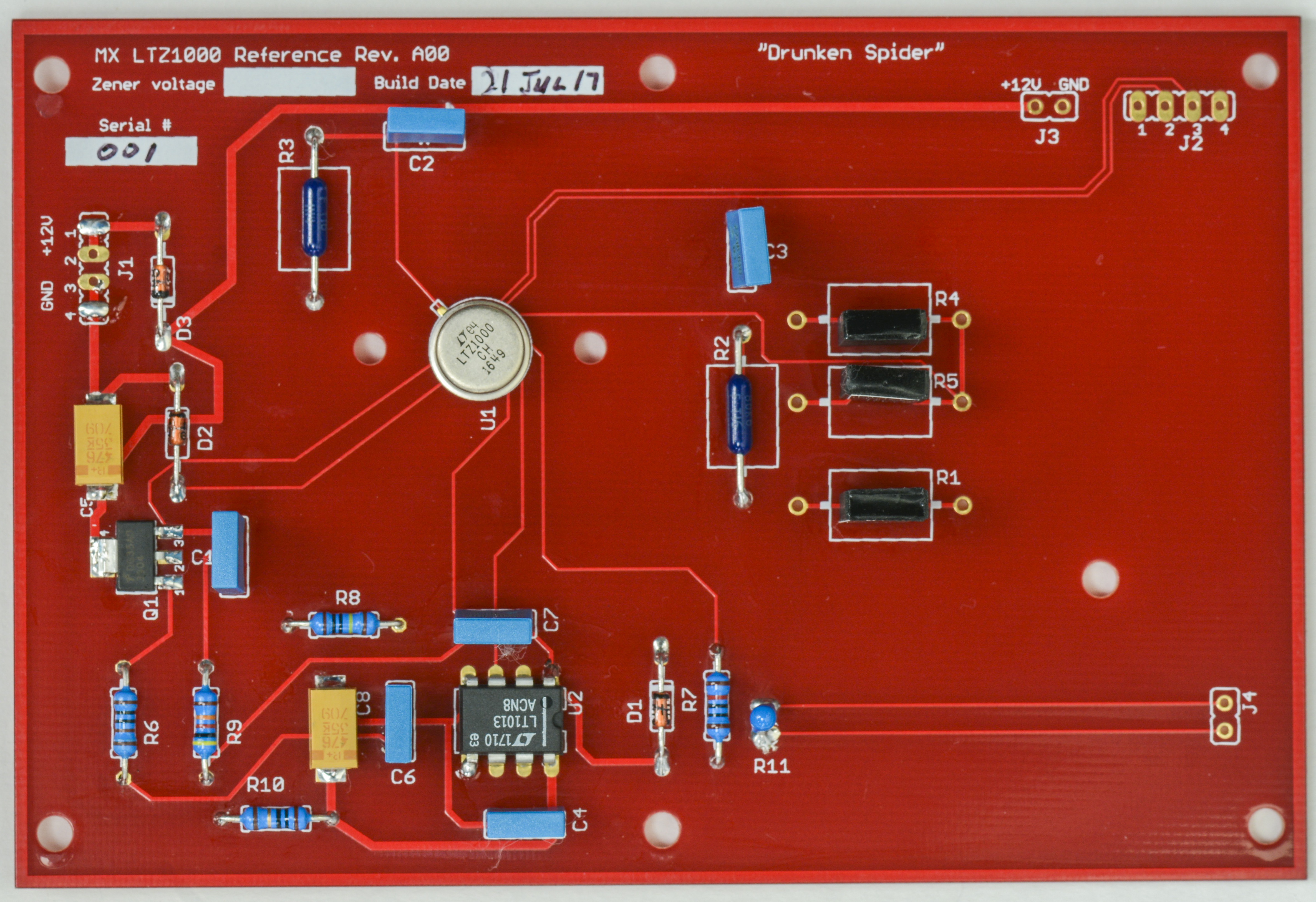
Image 3: xDevs.com MX voltage reference (Rev.A00) PCB cross-section
Image 3: xDevs.com MX voltage reference (Rev.A00) PCB cross-section
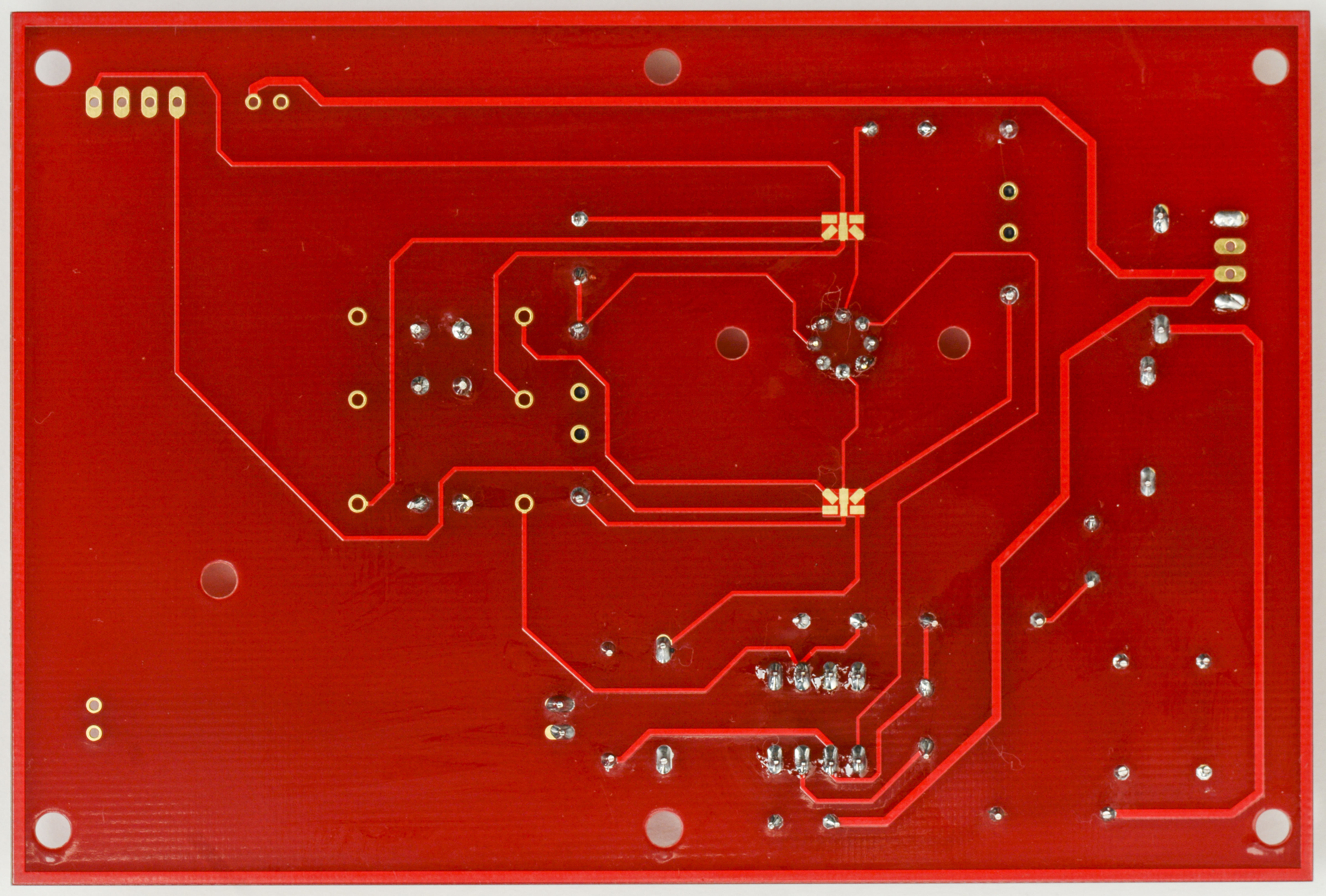
Image 3: xDevs.com MX voltage reference (Rev.A00) PCB cross-section

Image 3: xDevs.com MX voltage reference (Rev.A00) PCB cross-section

Image 3: xDevs.com MX voltage reference (Rev.A00) PCB cross-section
MX Voltage reference module designed for education and hobby experimentation purposes only, which resulted in used components choices. If one need ultra-stable voltage reference for production device or practical equipment, very different approach would be required. This includes adding necessary polarity/overload/ESD protection circuits to the input and outputs of the reference, etc.
To reduce thermal stress to foil resistors, heatsink legs with small pliers or braid during soldering, so resistor body would not heat up as much. Excessive heat on resistive element will cause stress and possible hysteresis, which will require long-term recovery to original state afterwards. Make your soldering brief and short. If solder joint not good, wait till board and resistor cool down back to ambient and then try brief reflow for bad connection again. Do not keep iron tip heating up resistor lead longer than few seconds.
Initial data results
Connect power to the modules from quiet (electric noise wise) linear power supply, leave to settle for few days/weeks/months and then measure with best stability multimeter available.
Make sure power supply polarity is correct before power on.
Reverse polarity even for brief seconds can reliably destroy expensive LTZ1000 chip.
Here are some measurements and test data completed on 5pcs LTZ1000 modules:
| Test result description | Datalog |
|---|---|
| Initial, 7.096052 V | 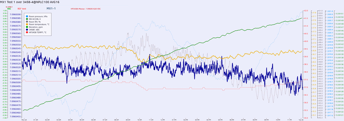 |
Table 8: xDevs.com MX reference module test log
If you interested in this project build or have any questions, feel free to jump in comments. We also have more detailed and less traditional KX LTZ1000-reference build so be sure to check that one out as well.
Projects like this are born from passion and a desire to share how things work. Education is the foundation of a healthy society - especially important in today's volatile world. xDevs began as a personal project notepad in Kherson, Ukraine back in 2008 and has grown with support of passionate readers just like you. There are no (and never will be) any ads, sponsors or shareholders behind xDevs.com, just a commitment to inspire and help learning. If you are in a position to help others like us, please consider supporting xDevs.com’s home-country Ukraine in its defense of freedom to speak, freedom to live in peace and freedom to choose their way. You can use official site to support Ukraine – United24 or Help99. Every cent counts.
Modified: Aug. 1, 2019, 9:15 a.m.