Before SSD’s become widely used and popular like they are today, in 2016, systems which needed high storage performance with minimal latency could be built using DRAM modules, like standard DIMM. Decade ago, in 2006, one of PC industry vendors, Gigabyte took a chance and developed iRAM or GC-RAMDISK which is basically a hardware emulation of SATA drive using dedicated FPGA logic with memory controller and four standard DDR1 memory slots and buffers.
This card plugs into system PCI slot to take power only and interfaces with standard SATA port as any usual harddrive. Speeds achievable with such a drive were near 150-170 MBytes/s, limited by SATA 1.5Gbps interface, but with very low access latency, often beating even today SSD’s. Memory capacity was limited by modules used, which in case if DDR1 UDIMMs was 1GByte/module or 4GB total.
Few other vendors released similar products, such as ACARD ANS-9010B. This device had different form-factor for 5.25” bay and sported DDR2 memory slots, providing support up to 64GBytes.
But this article is not a review, but rather a simple trick to get more of PCI iRAMs in your system. Starting from Intel SandyBridge from 2010, most of motherboards did not have PCI slots anymore to provide power for iRAMs, only PCI-Express. But plenty of us had old motherboards laying around, as since iRAM needs only power to charge it’s battery to hold reset active, easy adapter can be made to get iRAMs going.
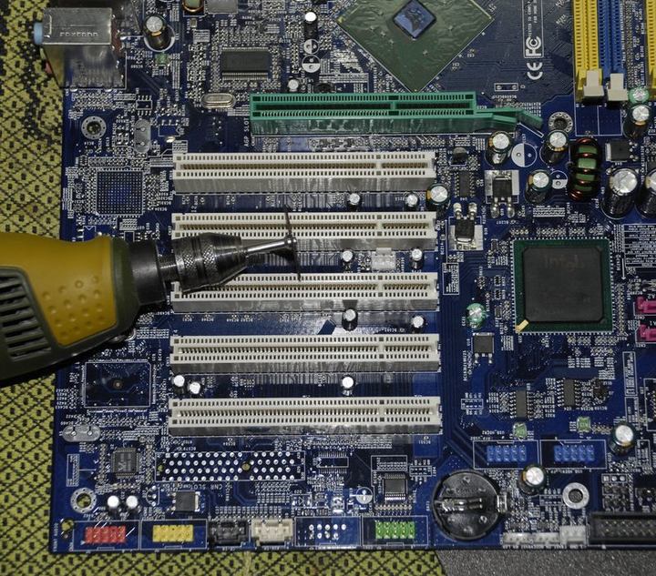
Old Foxconn Socket 478 motherboard for Pentium® 4 processors was cut and stripped to get PCI slots we need. To provide +3.3V to our PCI slots for connection with system PSU, dead WD Raptor 74GB HDD was found and used to get SATA power plug.
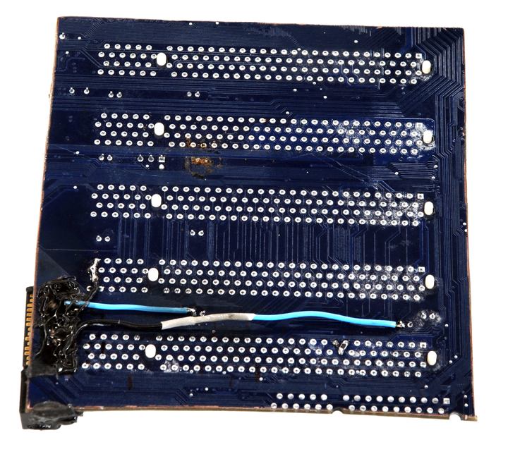
This will do just fine to power SATA connector for PCI board. Holes near edge of PCI board were drilled to allow SATA power connector wiring on pins.
Power rails from PSU : +3.3, +5 and +12V were routed to exact power nets of PCI circuitry. There is -12V pin also, but not used by I-RAMs, so it was left unconnected.
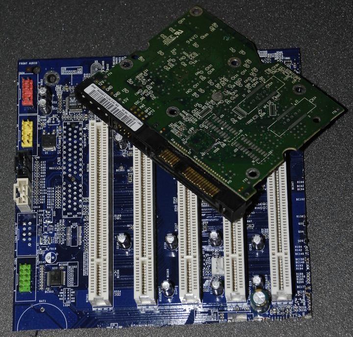
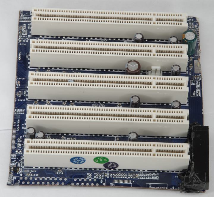
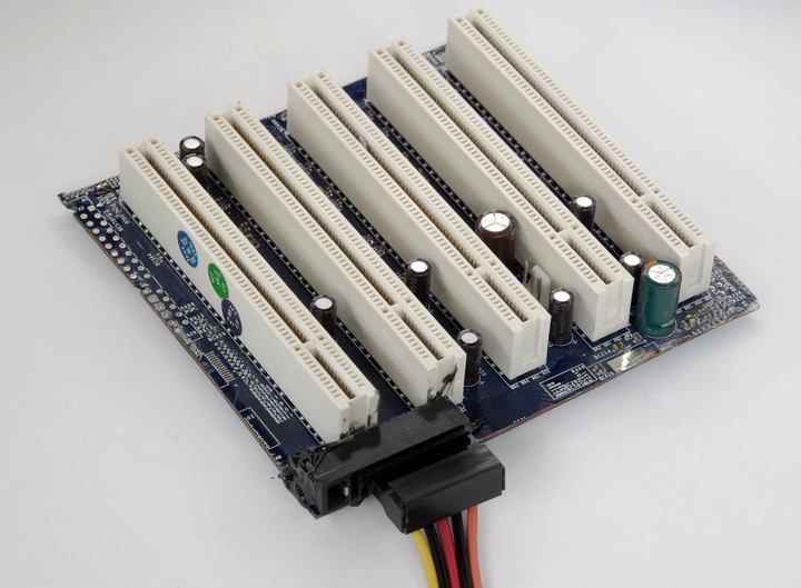
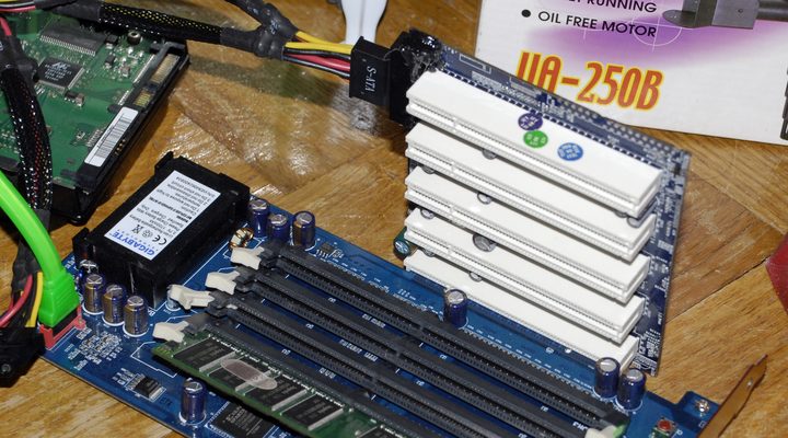
Why SATA power? Because it’s the only connector on usual PC PSU which have +3.3V on, except bulky 24pin main cable. Here’s end result what we got end up with.
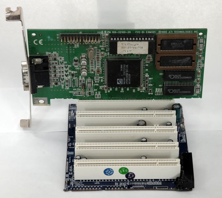
Front side, shows 5 useful powered PCI slots, with +5v compatibility key.
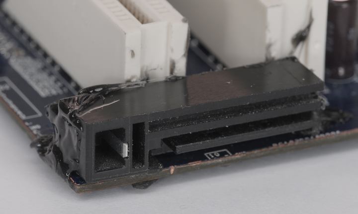
Bottom side with soldering involved:
With SATA power plug connected, ready to use.
One little catch – RESET signal on PCI slot must be pulled up to +3.3V with 10KΩ resistor to make i-RAMs out of reset and work.
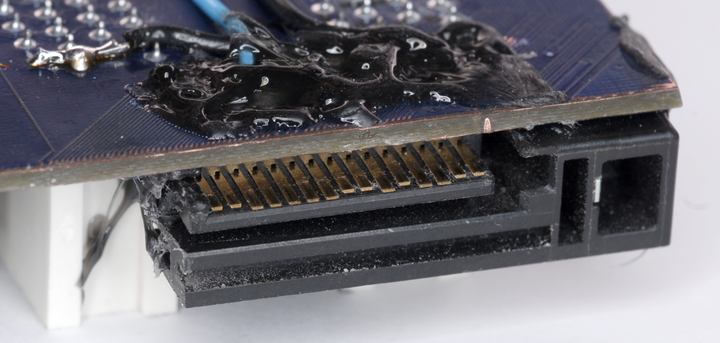
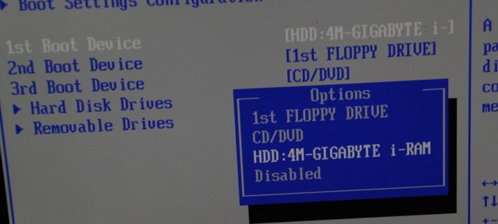
Now let’s plug actual ramdrive device in and check if it works.
Well, no surprises, everything is just fine.
Time used:
- 30min to dig scrap
- 5min to cut PCI off the board
- 20min for reading SATA and PCI standards to ensure everything is OK
- 5 min for googling I-RAM pics to see what and where connected from slot
- 30min for soldering and taking photos.
Total : 1.5 human-hours.
Hope this article will help you to think wide and sometimes solution is just right next to you. Stay tuned.
Projects like this are born from passion and a desire to share how things work. Education is the foundation of a healthy society - especially important in today's volatile world. xDevs began as a personal project notepad in Kherson, Ukraine back in 2008 and has grown with support of passionate readers just like you. There are no (and never will be) any ads, sponsors or shareholders behind xDevs.com, just a commitment to inspire and help learning. If you are in a position to help others like us, please consider supporting xDevs.com’s home-country Ukraine in its defense of freedom to speak, freedom to live in peace and freedom to choose their way. You can use official site to support Ukraine – United24 or Help99. Every cent counts.
Modified: March 24, 2016, 2:26 p.m.