Some time ago, during sleep-less lurks on online auctions, lot of precision Fluke resistor networks was bought. Resistors are manufactured by Benchmark electronics. They happen to be ones used in Fluke 8845/8846A series DMMs, hermetically sealed laser-trimmed film networks, made by Fluke. These resistor networks type are widely used in metrology equipment from Fluke and other vendors, to ensure long-term stability and good thermal matching performance.
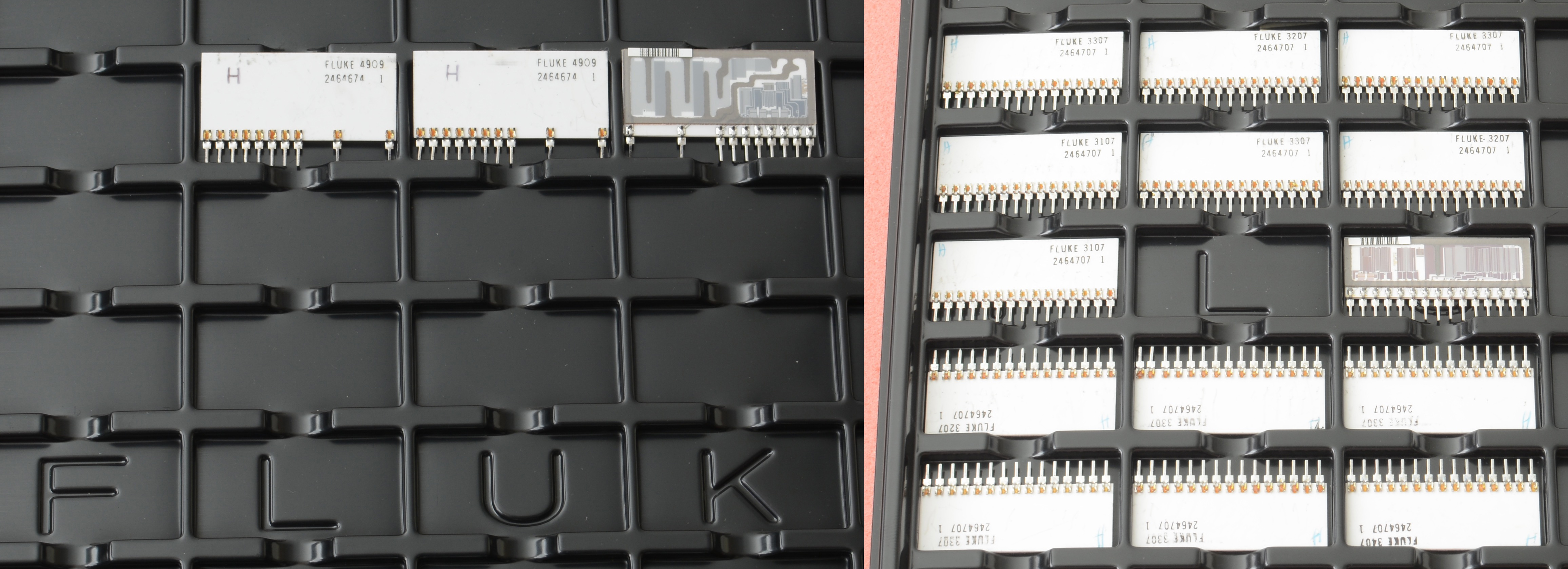
Image 1: Fluke P/N 2464707 reference/gain precision hermetic resistor
The only better design are specially manufactured wire-wound hermetic assembies and metal foil resistors, but to build network with more than few resistors would require tremendous efforts (reflected in price as result).

Image 2: Fluke resistors
To less critical applications these film networks on ceramic substrate would work great. Substrate also help to keep thermal gradients minimal, helping for applications where matching ratio between resistors may be more important than absolute best tempco/value.
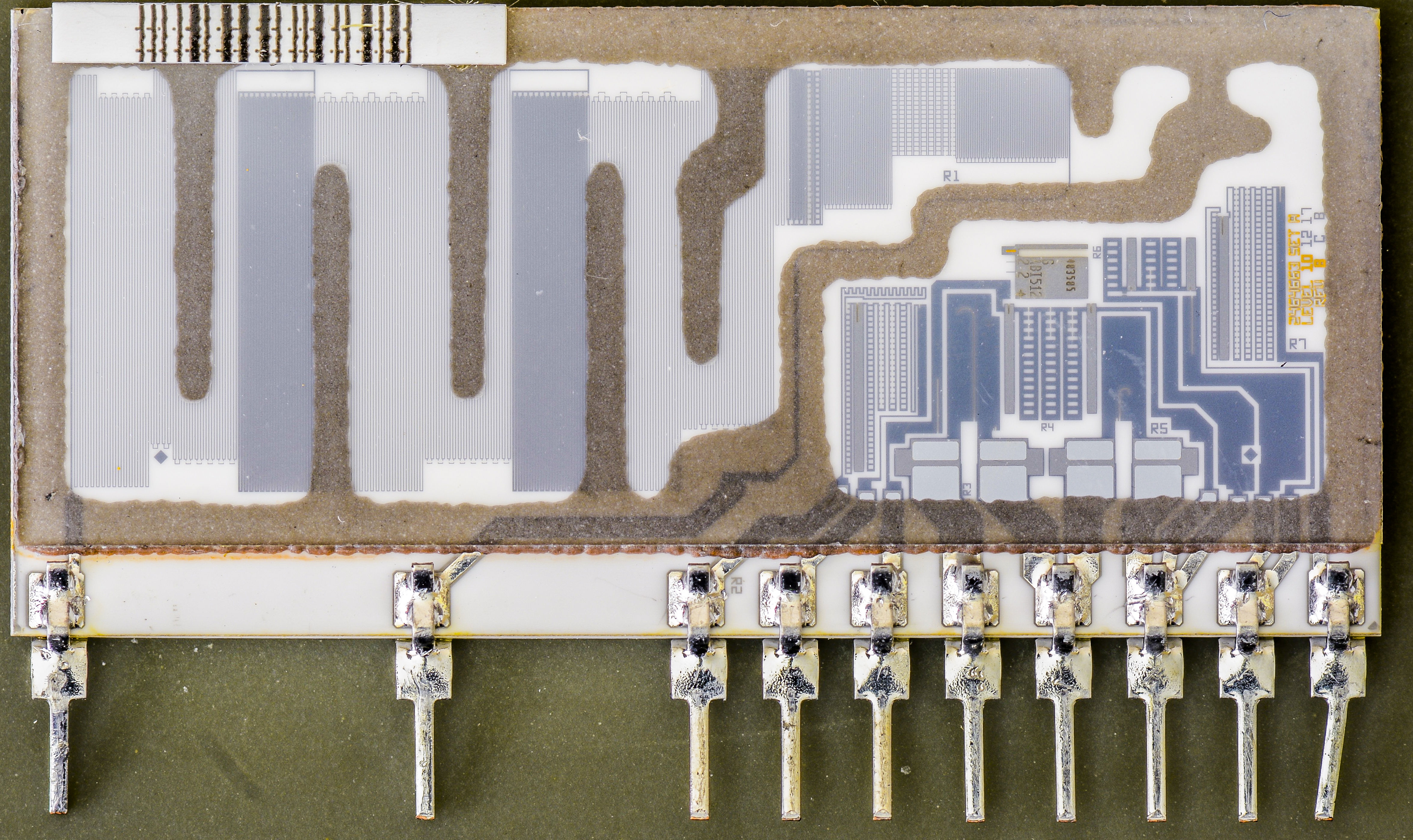
Image 3: Fluke P/N 2464674 High-voltage divider precision hermetic resistor
Fluke network P/N 2464674 is used in front end analog, to divide high-voltage ranges to acceptable ADC input levels and to provide scaling for some other functions of the meter. High-value 10 MΩ resistor clearly visible by large area of thin serpentine resistive material trace. Since there is no public schematics for Fluke 8846A DMM, we can only guess from the common sense of typical front-end analog design, used in other similar meters.
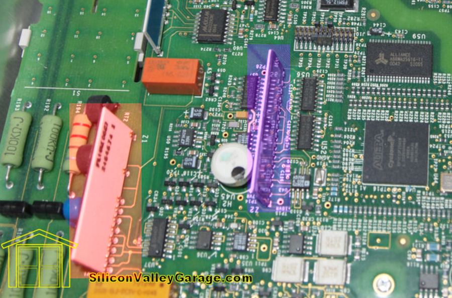
Image 4: Fluke 8846A internal design. Courtesy free_electron, EEVBlog Forum .
On Image 2 resistors in question are marked by red color for high voltage divider resistor 2464674, and second 2464707 network used for LM399 DC voltage reference highlight in blue color.
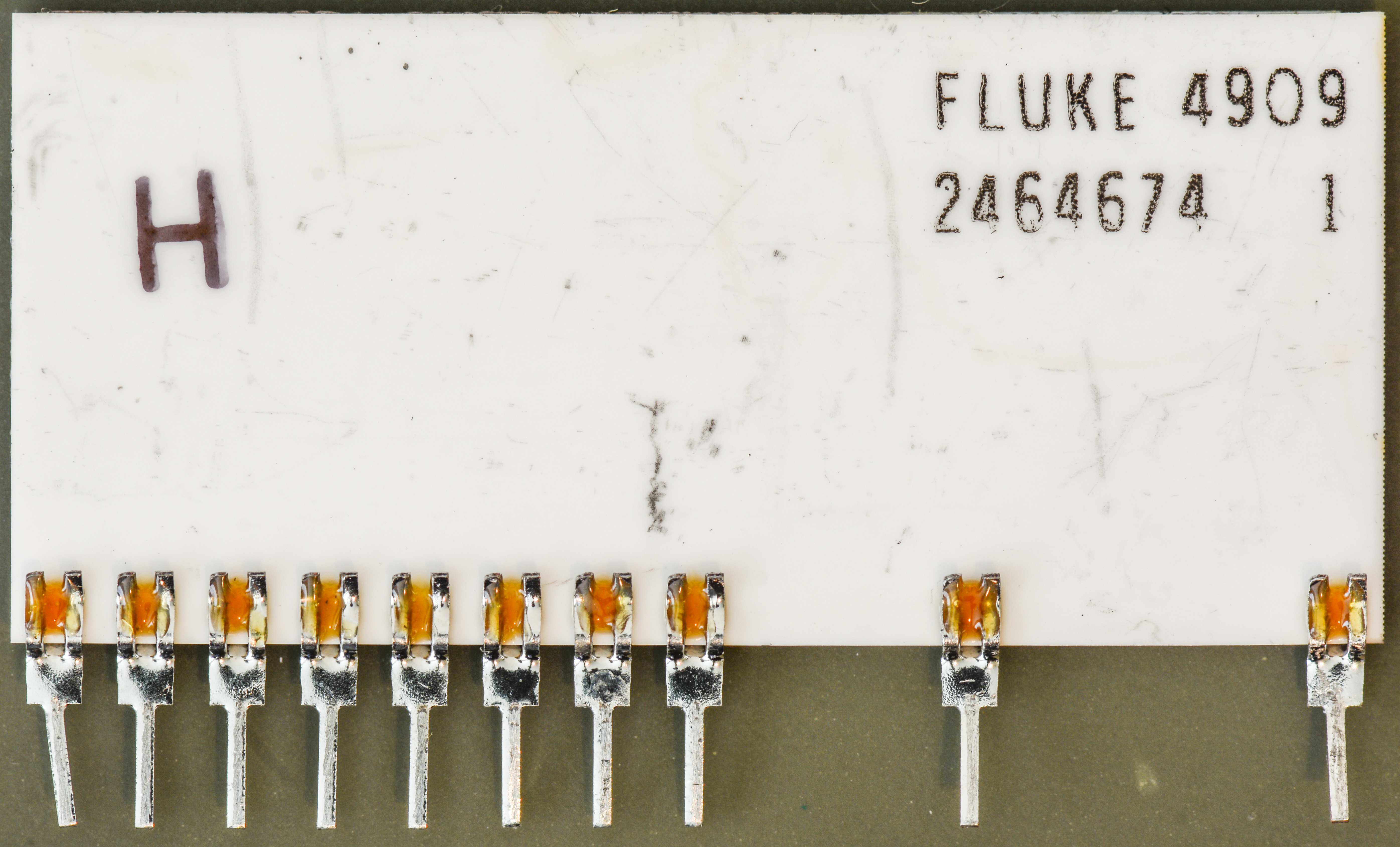
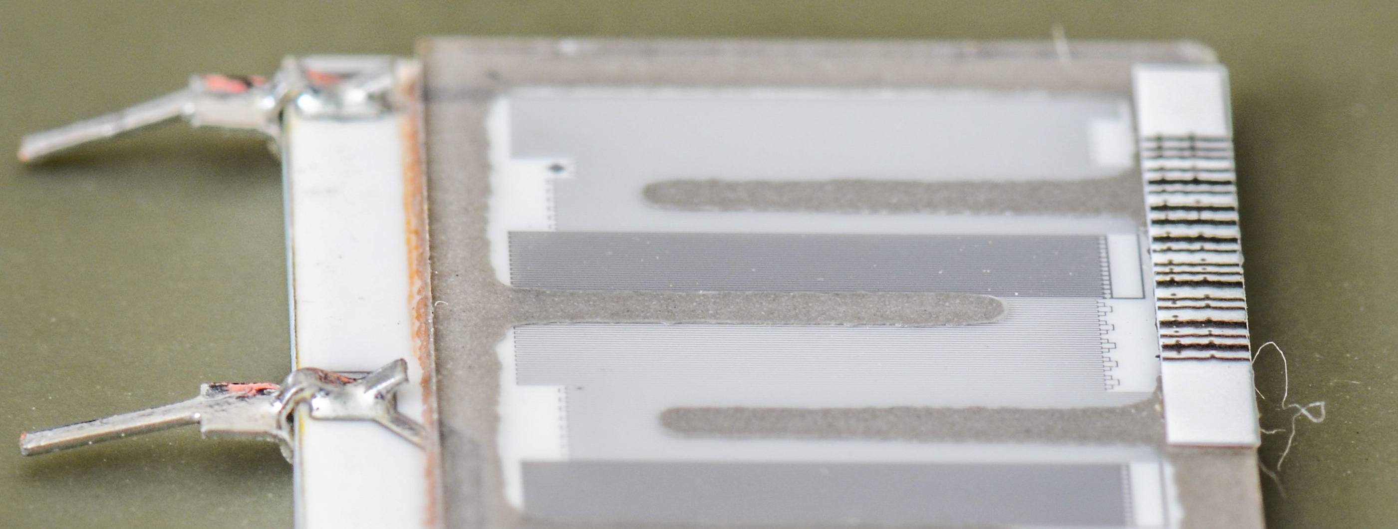
Image 5-6: Fluke P/N 2464674 custom precision hermetic resistor, back
Next is hermetic resistor network used for LM399 DC voltage reference circuit to generate +10V output and provide other functions to meter circuits.

Image 7: Fluke P/N 2464707 reference/gain precision hermetic resistor
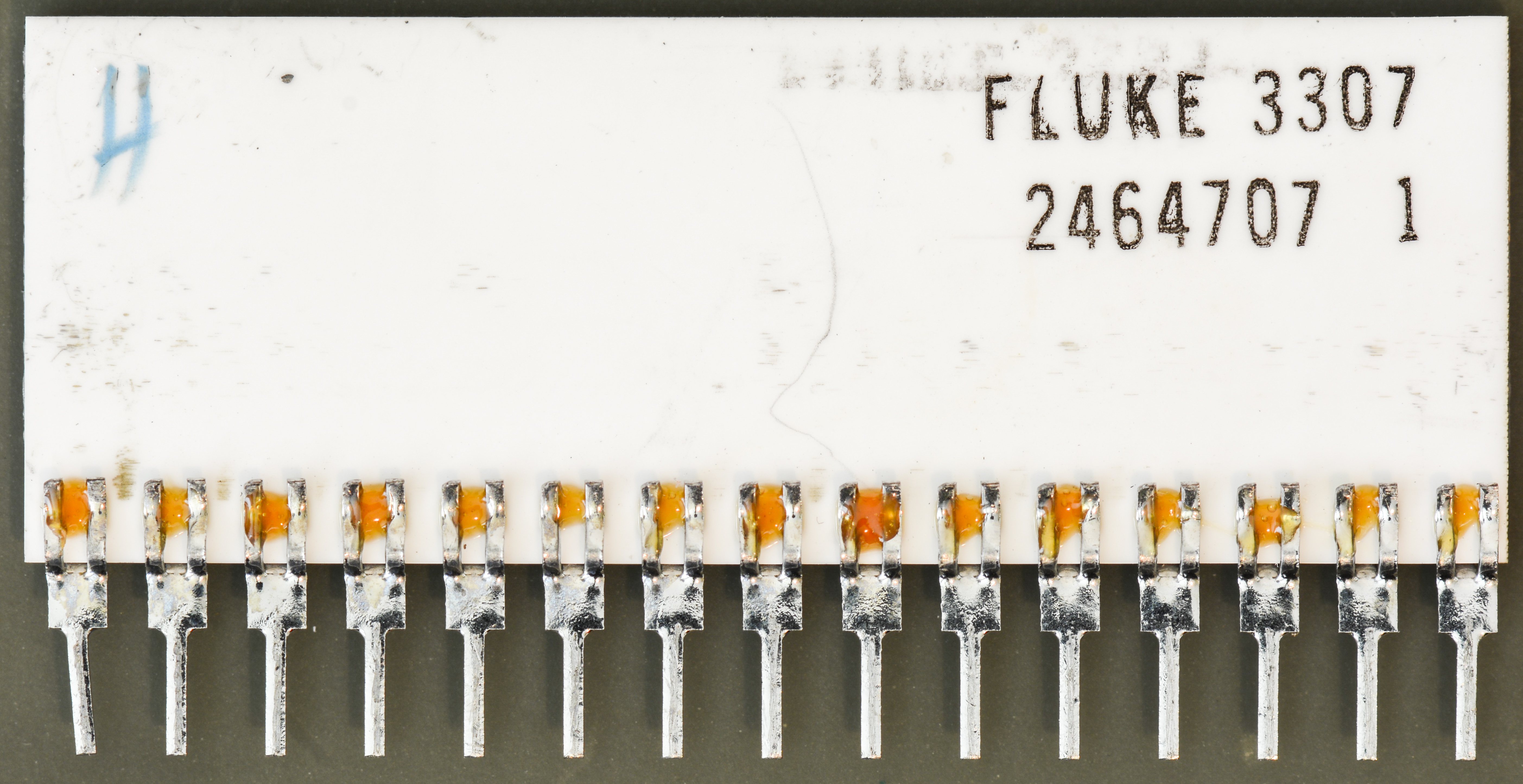
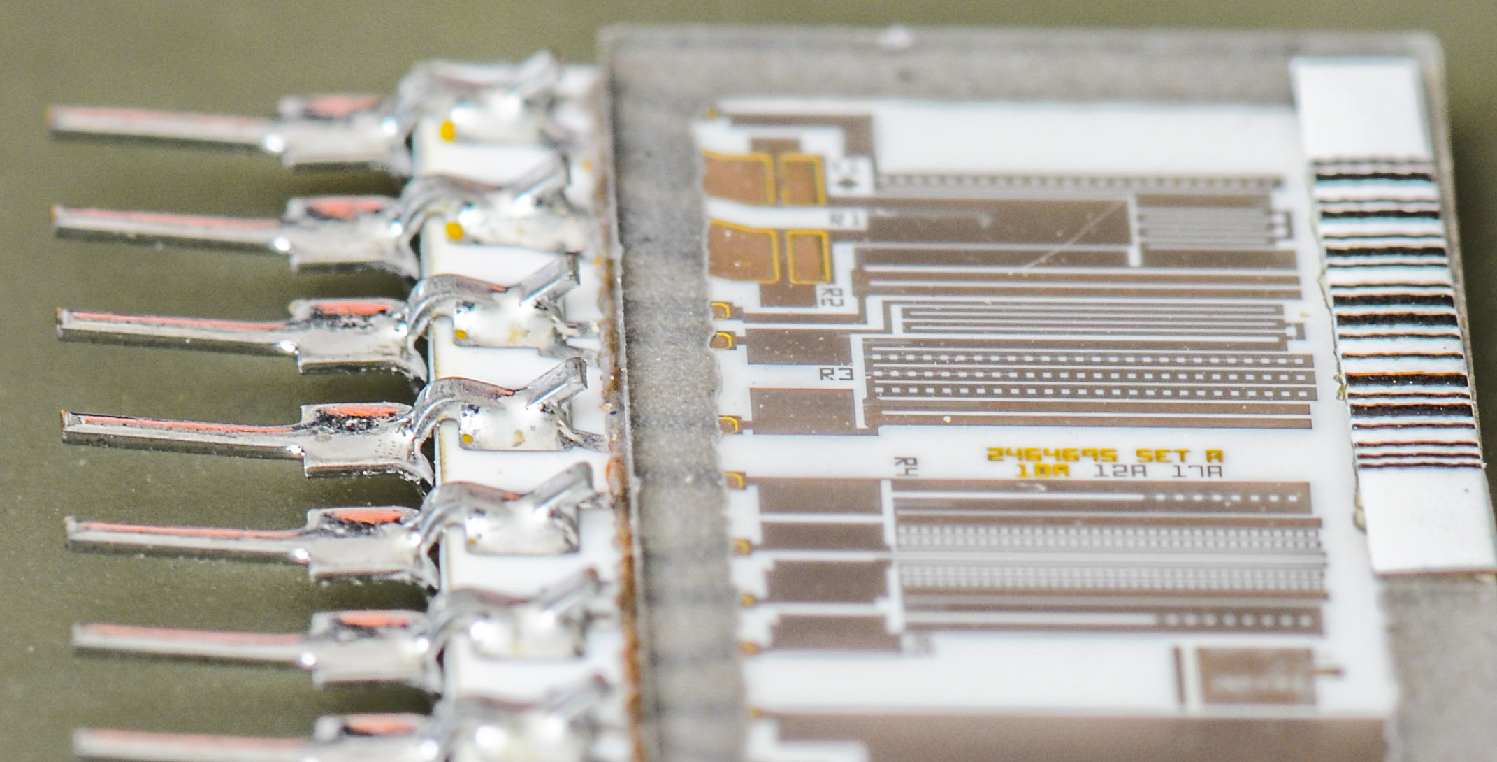
Image 8-9: Fluke P/N 2464707 reference/gain precision hermetic resistor, back
Some quick measurements for resistance across various pins:
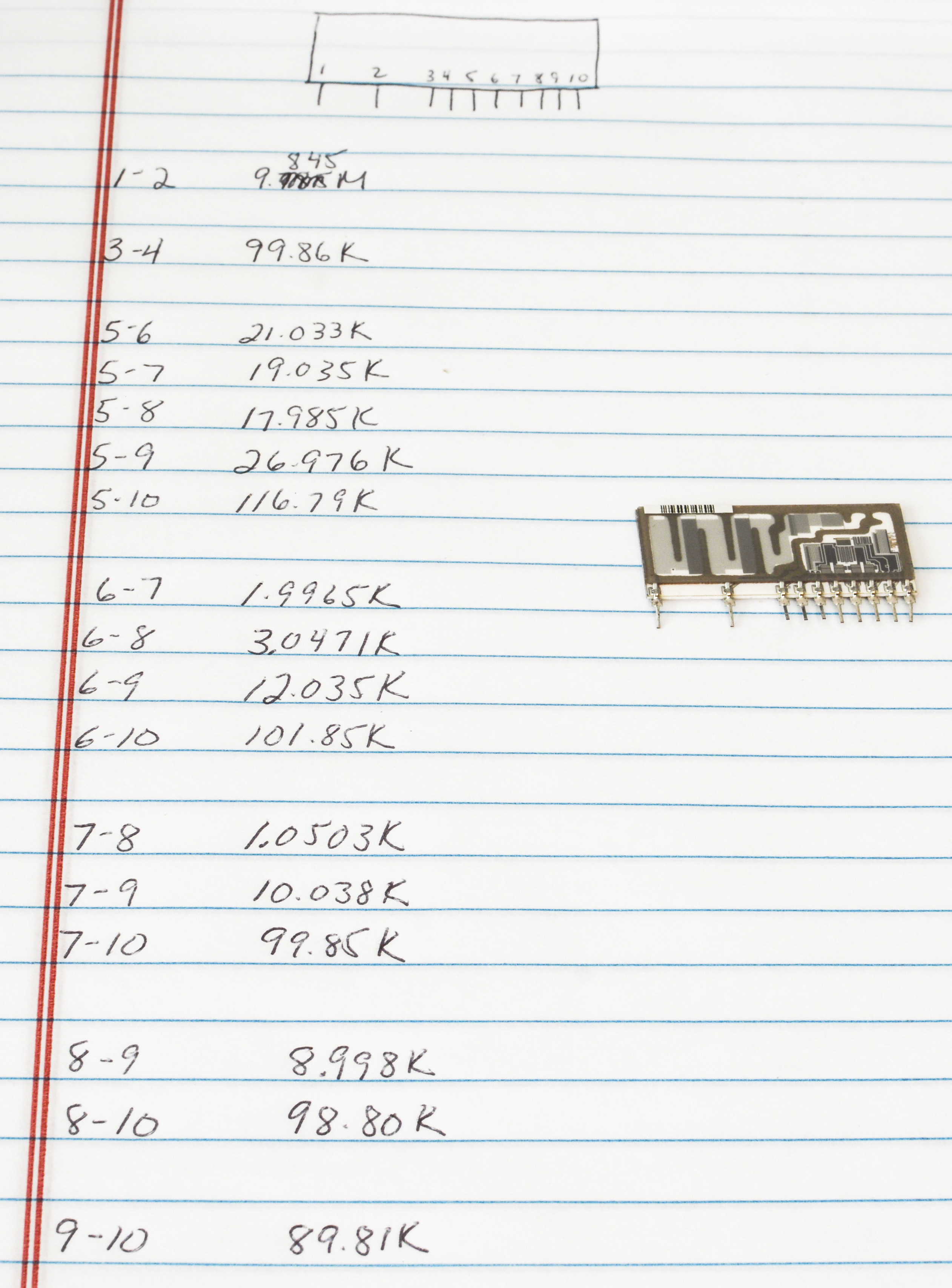
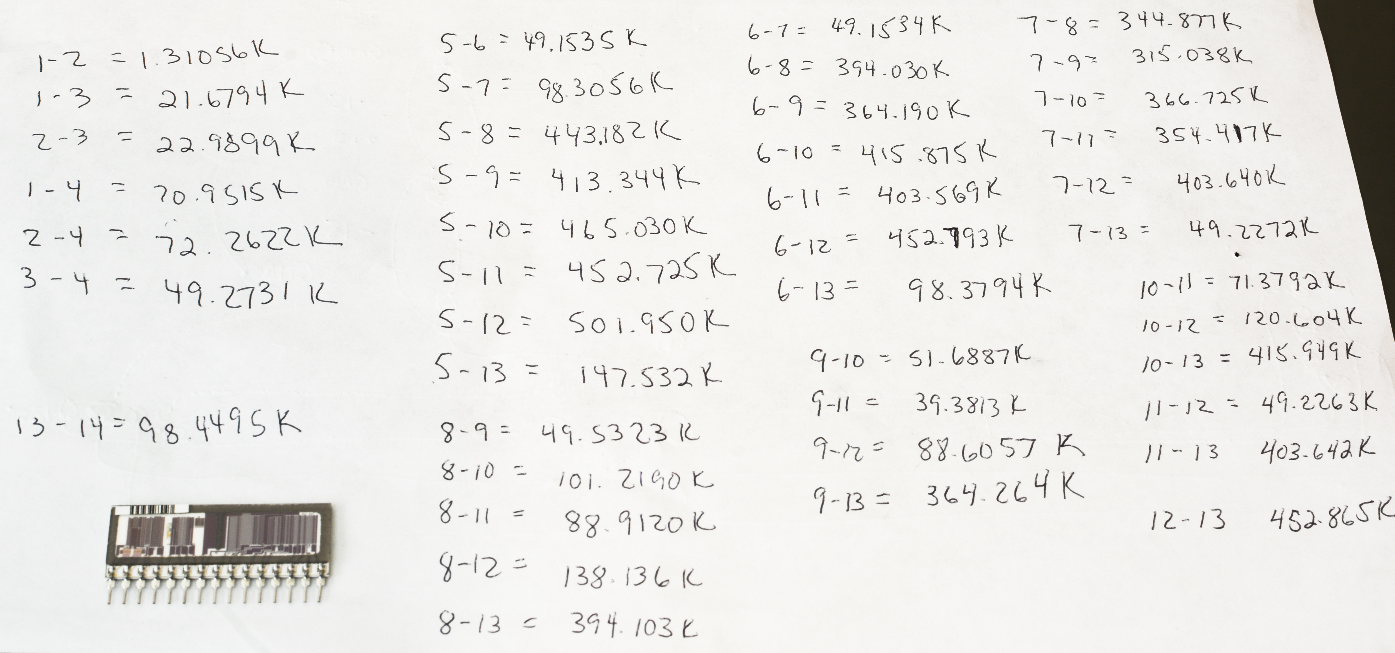
Image 10-11: Fluke resistors measurements
How we can analyze resistor layout and recover full schematics of both networks. David. L. Jones from EEVBlog did a very good video explaining how these resistors are designed and trimmed, on example of ones used in another 7½-digit precision DMM, Keithley DMM7510 (Model 2040).
Recovered schematics of both resistor networks.
Reference resistor network:
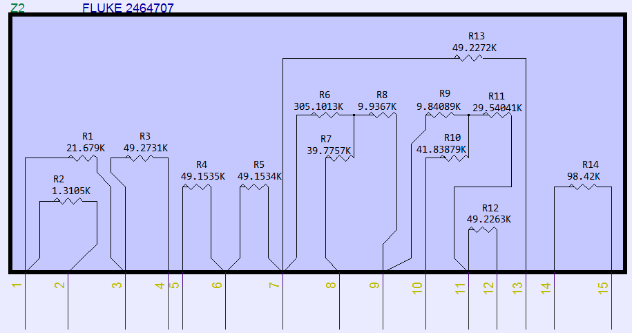
Image 12: Fluke P/N 2464674 resistor schematics
It is obvious how this resistor sections R1,R2,R3 are used to convert typical +6.95 VDC from LM399 buried zener output to +10 VDC voltage.
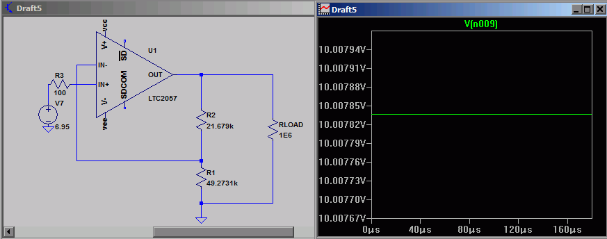
Image 13: LTSpice simulation with chopper opamp to illustrate 7V->10V conversion, LM399 6.95V typical
Also it’s possible to tweak connections a little bit for more stable LTZ1000-based design.
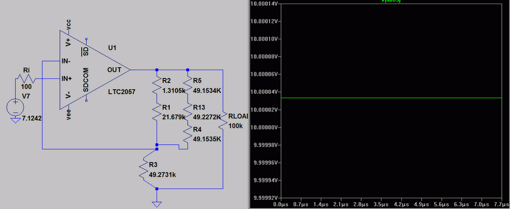
Image 14: LTSpice simulation with chopper opamp to illustrate 7V->10V conversion, LTZ1000 7.1242V chip
Measurement of T-resistor network sections was performed using Fluke 5700A calibrator as DC current source and HP 3458A as DC voltmeter. As total resistance easy to check, remaining network arrangement is just simple math.
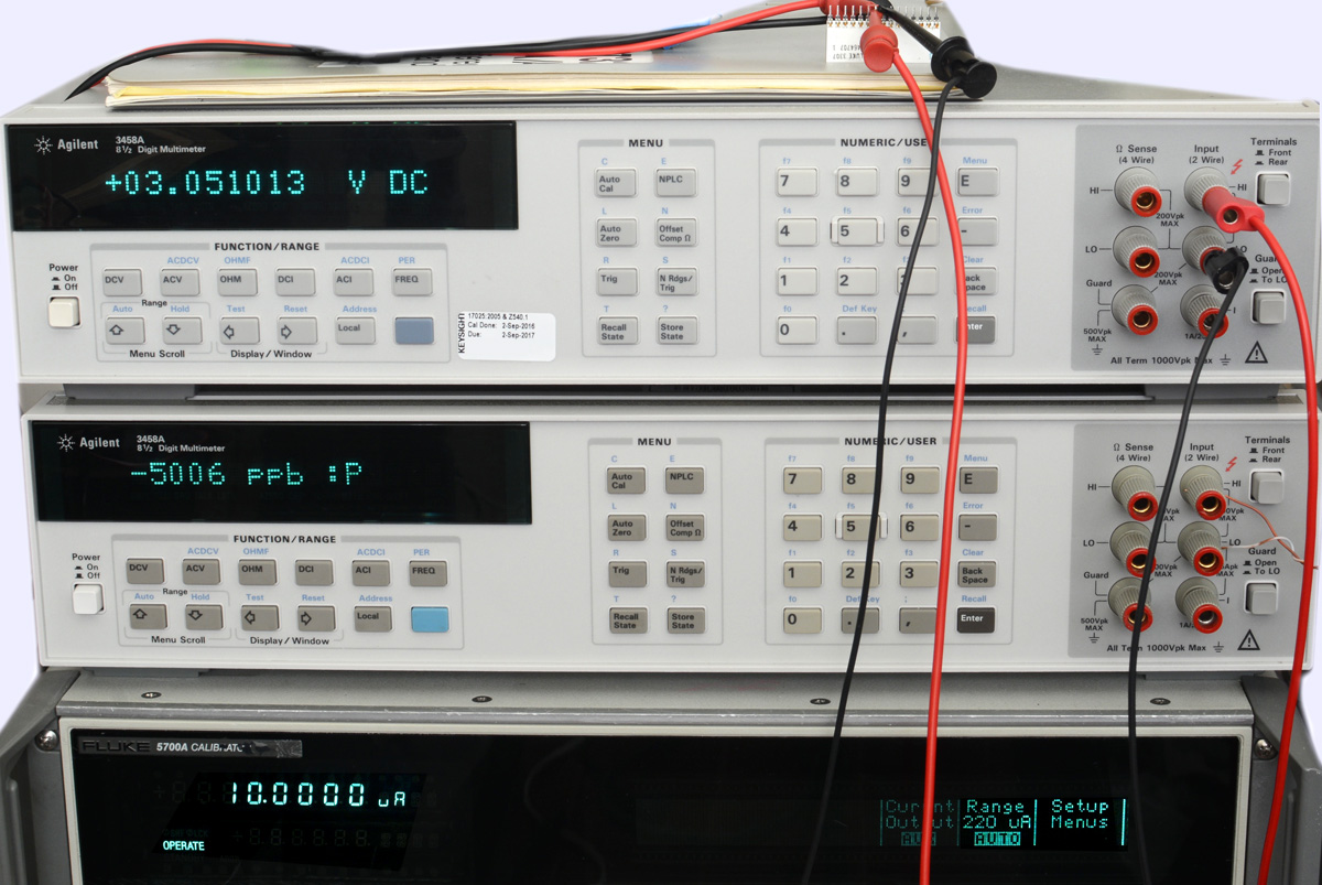
Image 15: Test setup for resistance measurement
And finally high-voltage divider resistor:
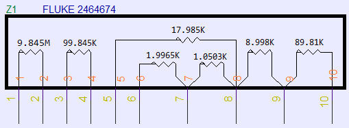
Image 16: Fluke P/N 2464674 resistor schematics
Some other similar type Fluke networks part numbers:
| FPN | Package | Description | Measured elements | Datecode |
|---|---|---|---|---|
| 626629 | SIP-15, populated 1,8,10,11,12,13,15 | 8508A Ohm A3 PCBA | ? | 40 week 2001 |
| 1614401 | SIP-15, populated 1,8,10,11,12,13,15 | 8508A Ohm A3 PCBA | ? | 40 week 2001 |
| 3039537 | SIP-15, populated 1,11,13,14,15 | 8508A ACV PCBA, attenuator | ? | 14 week 2014 |
| 3034193 | SIP-15, populated 2,3,4,6,7,8,9,11,12,13,14 | 8508A ACV PCBA, attenuator | ? | 9 week 2014 |
| 1614394 | SIP-15, populated 1,8,10,11,12,13,15 | 8508A DCV PCBA | ? |
Projects like this are born from passion and a desire to share how things work. Education is the foundation of a healthy society - especially important in today's volatile world. xDevs began as a personal project notepad in Kherson, Ukraine back in 2008 and has grown with support of passionate readers just like you. There are no (and never will be) any ads, sponsors or shareholders behind xDevs.com, just a commitment to inspire and help learning. If you are in a position to help others like us, please consider supporting xDevs.com’s home-country Ukraine in its defense of freedom to speak, freedom to live in peace and freedom to choose their way. You can use official site to support Ukraine – United24 or Help99. Every cent counts.
Modified: Oct. 25, 2023, 2:50 a.m.