- Intro
- Disclaimer
- Manuals and service information
- Exterior
- Design and internal design
- Control application features
- Cryocooler first test
- RF filter + LNA benchmarks
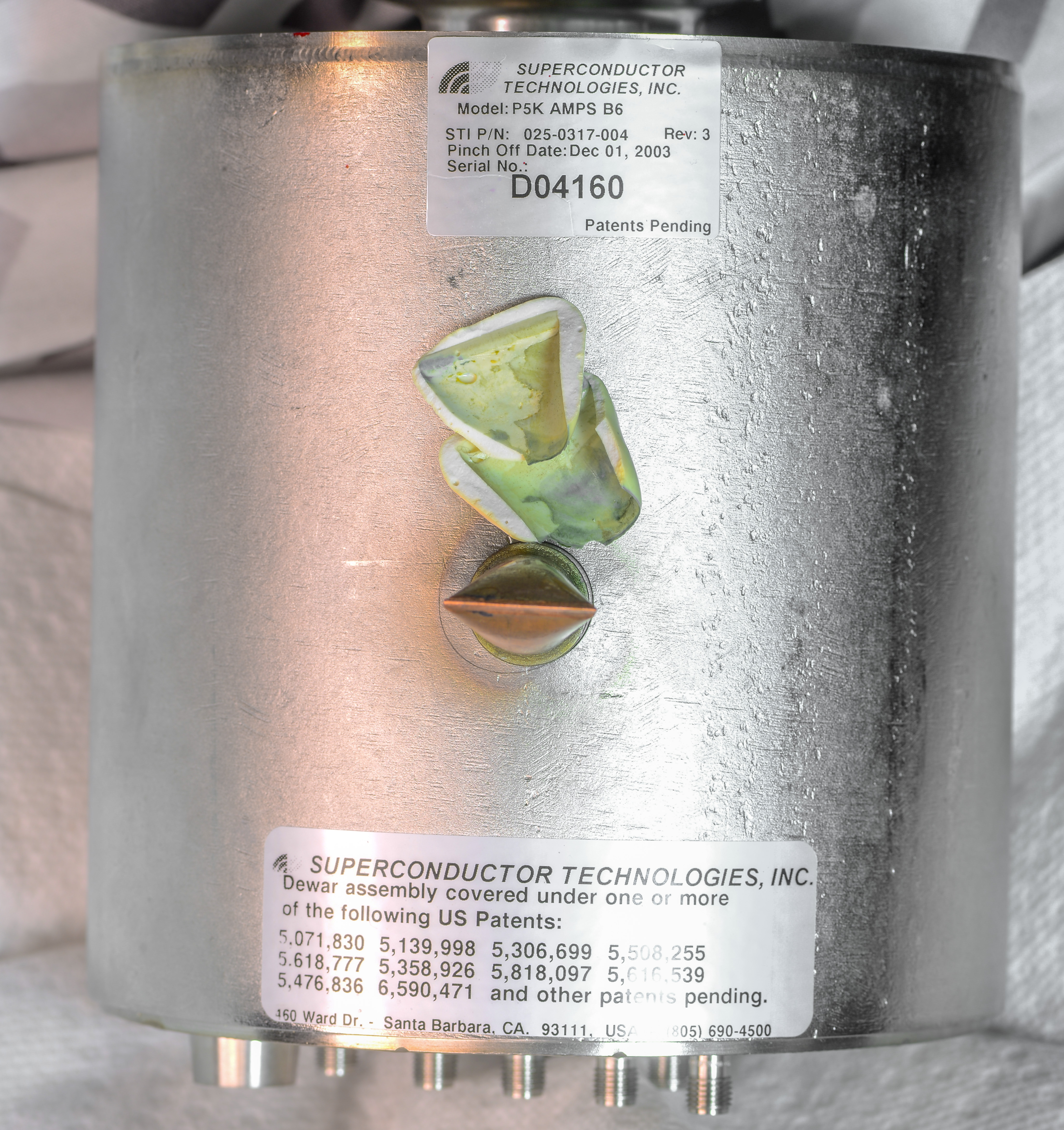
- Dewar assembly teardown
- Conclusion
Intro
I’ve used liquid nitrogen for years to cool high-power computer CPUs and GPUs in pursue of higher frequencies and performance. What started as hobby once, is now part of my daily job, and cooling semiconductor devices down to -196 °C is not unusual for me anymore. This also reflected in design and CAD design support Kingpincooling.com for various copper heat evaporator blocks. These niche products provide entry point for anyone who’d like to try cryogenic cooling for PC. In computer industry overclocking with liquid nitrogen cooling have purely sport entertainment purpose. It is also indicator of what future processors and graphic cards may achieve, if not thermal or power constrains. However actual useful and practical applications of such low-temperature cooling concepts also well exist in the electronics industry.
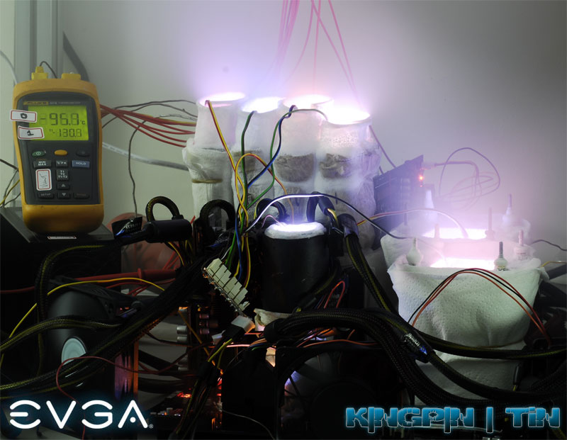
Image 1: Extreme cryocooled rig with four GeForce GTX 580 and EVGA SR-2 dual-socket CPU board
These practical applications of electronics cooled down to liquid-nitrogen temperatures are often related to specialized analog sensors, scientific research, high-temperature superconductor device use, ultra-low noise RF filters and amplifiers, chemical materials research and metallurgy. Traditional low-temperature superconductors include infamous primary voltage standards, like Josephson Junction Array and SQUID require even colder temperatures, with help of liquid helium or complex multi-stage cryosystems. Quantum devices are also operate at temperatures very close to absolute zero on Kelvin scale.
However using liquid cryogenic coolant for continuous operation is not convenient, it require large vacuum-insulated Dewar tanks, transportation and storage difficulties, and so on. If heat load of device that need to be cooled is small. Alternative solution to all this messy business like use of the closed-cycle cryocooling engine. Compressors with helium gas as a working body are often used to cool small DUT devices down to 77 K or even colder temperatures.
We got our hands on such cryocooled semiconductor system, in shape of the old cellular base station RF filter, Model 850SLB6F1R SuperLink Rx. These devices made by Semiconductor Technologies, designed to improve RF receive path quality of the cellular base station. Superconducting low-noise filter or amplifier circuitry working in 840 MHz B-Band frequency range chilled to temperatures below -190 °C during continuous operation 24/7. It is essentially a highly selective and sensitive low-noise RF filter used to clean the receive path of wireless base stations.
Handling cryogenic liquids and cryogenic coolers can be dangerous and require personal protection equipment. LN2 is very cold substance at -196 °C (-320 °F) and can cause severe frostbite or suffocation. Nitrogen’s critical point is 126.2 K, as result it cannot stay liquid at ambient temperature at any pressure. If sealed in the container, this will cause explosion. LN2 also have gas to liquid ratio 700 to 1, so it can displace all oxygen in the closed room and cause suffocation without warning. Never use LN2 in a small poorly ventilated room. Treat liquid nitrogen and any cooled object with respect.
Disclaimer
Redistribution and use of this article, any parts of it or any images or files referenced in it, in source and binary forms, with or without modification, are permitted provided that the following conditions are met:
- Redistributions of article must retain the above copyright notice, this list of conditions, link to this page (https://xdevs.com/article/sti/) and the following disclaimer.
- Redistributions of files in binary form must reproduce the above copyright notice, this list of conditions, link to this page (https://xdevs.com/article/sti/), and the following disclaimer in the documentation and/or other materials provided with the distribution, for example Readme file.
All information posted here is hosted just for education purposes and provided AS IS. In no event shall the author, xDevs.com site, or any other 3rd party, including Superconductor Technologies be liable for any special, direct, indirect, or consequential damages or any damages whatsoever resulting from loss of use, data or profits, whether in an action of contract, negligence or other tortuous action, arising out of or in connection with the use or performance of information published here.
If you willing to contribute or add your experience regarding instrument repairs or provide extra information, you can do so following these simple instructions
Manuals and service information
SuperFilter Operation and Installation Manual, SN00673 and up, September 21, 2000
SuperLink Rx 1900 Operation and Installation manual
SuperLink Rx Operation and Installation Manual, March 5, 2004
SuperFilter Operation and Installation Manual
Patent, Stirling Cycle Cryocooler with Optimized Cold End Design
Patent, Electromechanical transducer particularly suitable for linear alternator.
Patent, Fluid bearing with compliant linkage for centering reciprocating bodies.
Patent, Cryocooler housing assembly apparatus and method.
Patent, Cryocooler with moving piston and moving cylinder.
Patent, Tower mountable cryocooler and HTSC filter system.
Patent, Cryocooler motor with split return iron.
Patent, Controlled thallium oxide evaporation for thallium superconductor films and reactor design.
Patent, Epitaxial Thallium HTS films formed via a nucleation layer
Patent, High temperature superconductor lumped elements and circuit.
Patent, Temperature controlling cryogenic package system
Patent, HTS Lumped Element Band-Reject filters.
Patent, Temperature control of HTS thin film filter subsystems
Patent, Push on connector for cryocable and mating feedthru
Also interesting research work about STI’s design outlined here:
Practical Cryogenic Receiver Front Ends for Commercial Wireless Applications, Balam A. Willemsen
Exterior
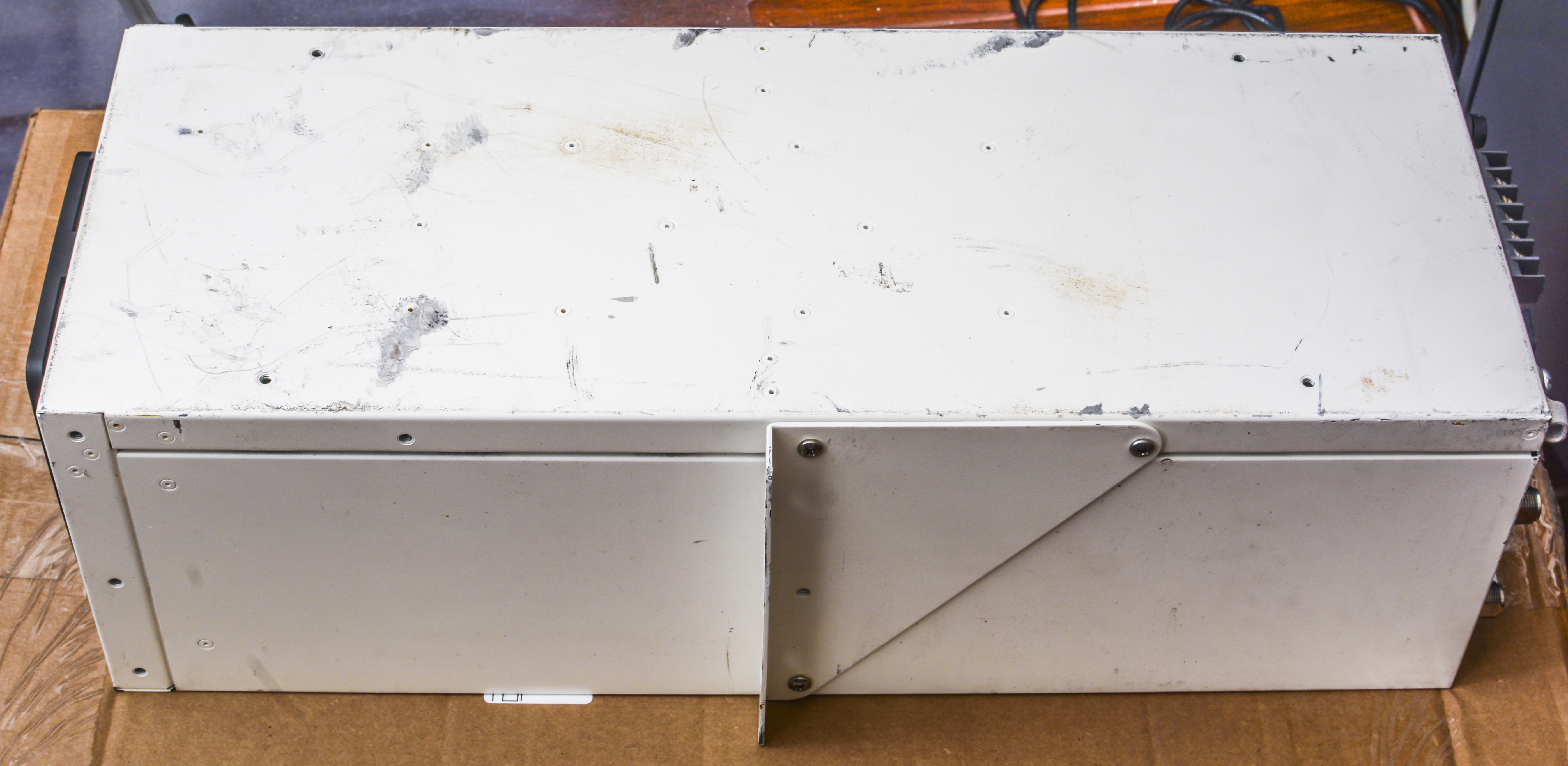
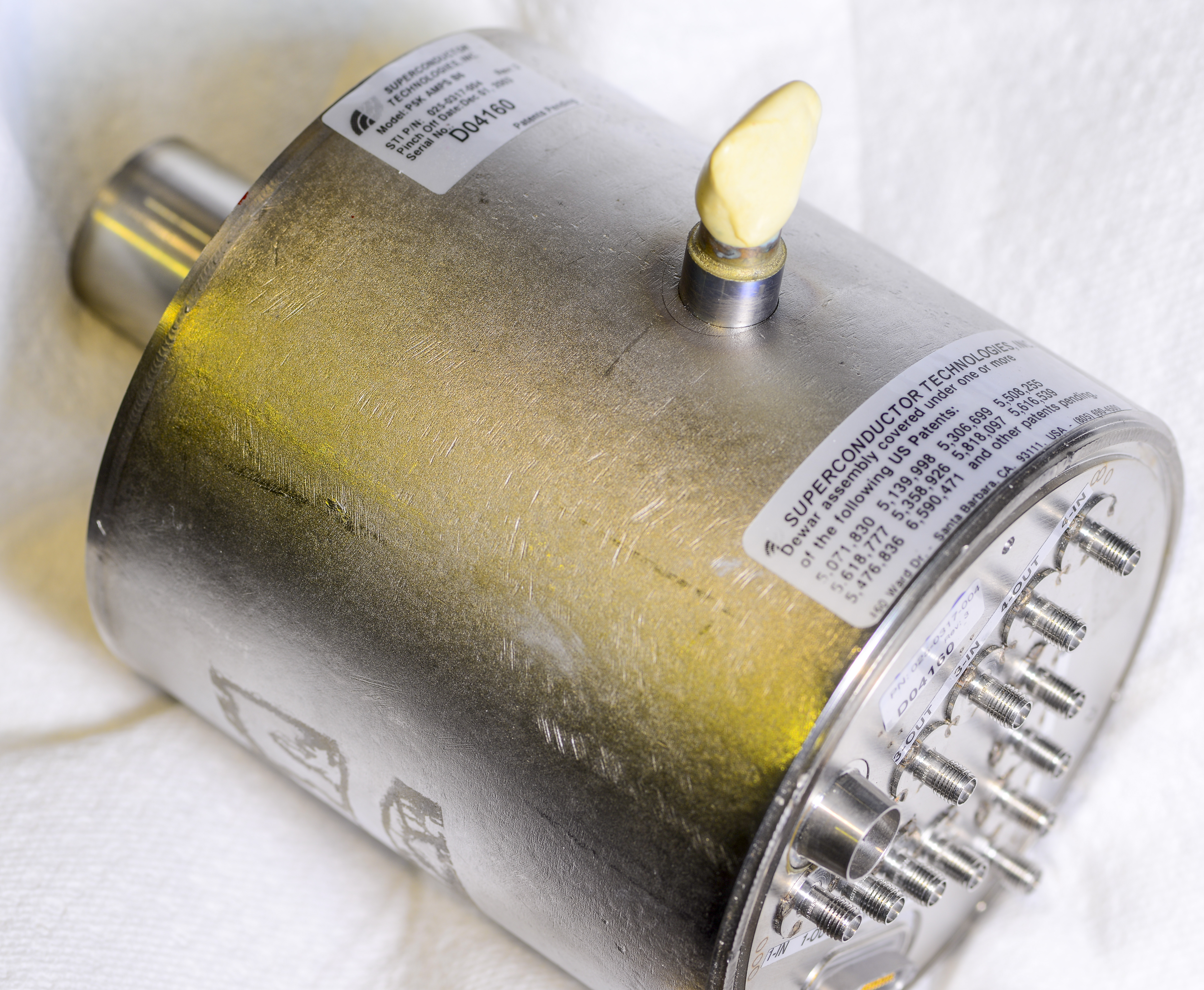
Image 2: STI SuperLink RX in it’s beaten exterior shape
Label is quite interesting too, Dangerous goods from Great Saline! It’s not a surprise, because superconducting material in the RF section contains Thallium metal, which is toxic. It was used as strong rats poison in the past.

Thallium and its compounds are highly toxic. Contact with skin is dangerous. Thallium and Thallium salts are colorless, odorless and tasteless. Thallium poisoning with slow-acting, painful and wide-ranging symptoms are often suggestive of a host of other illnesses and condition. Never disassemble, grind, lap, fire or chemically clean LNA assembly package to avoid health hazard risks.
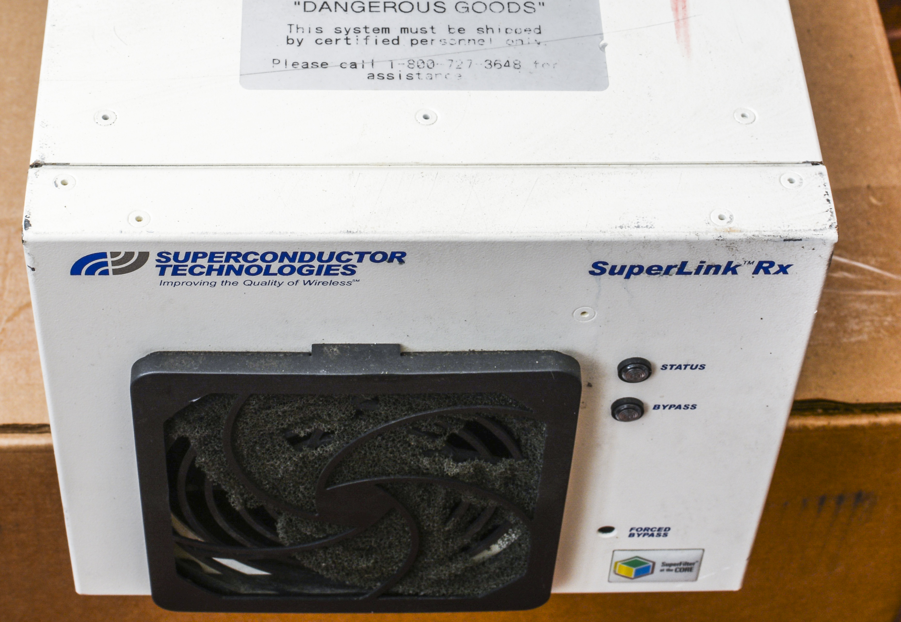
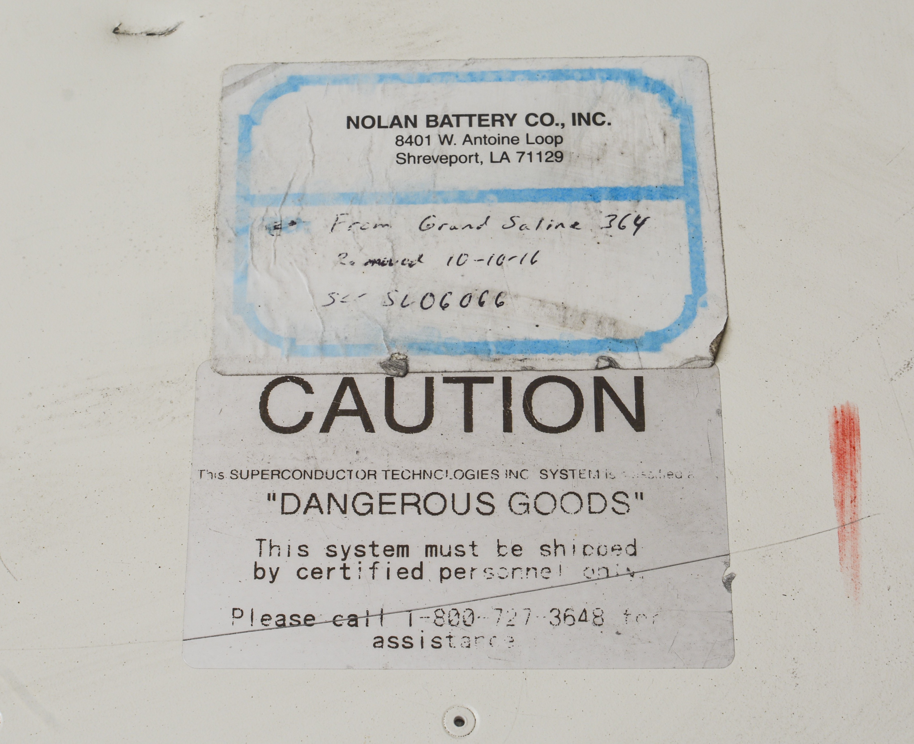
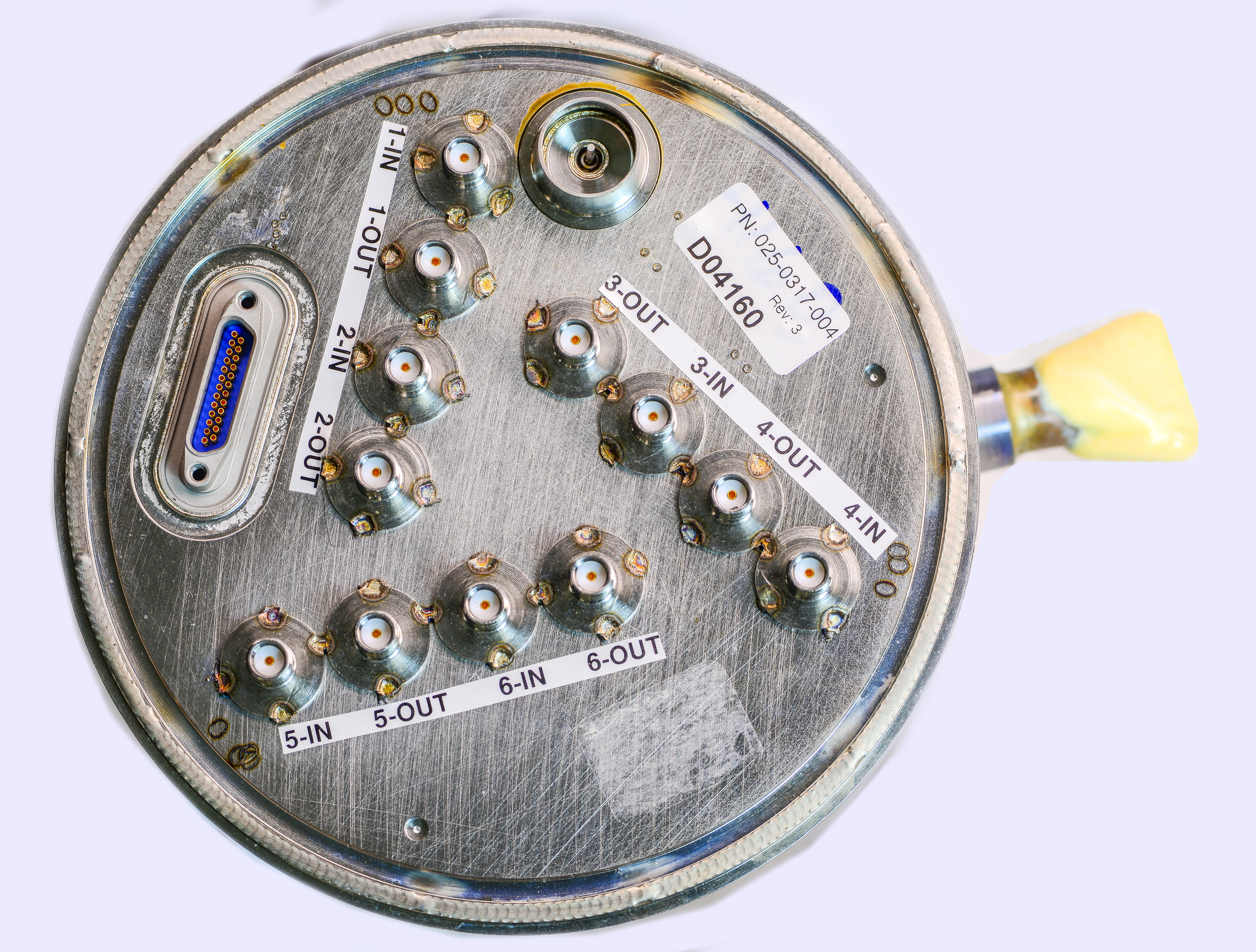
Image 3-4: Front face and warning labels on top cover.
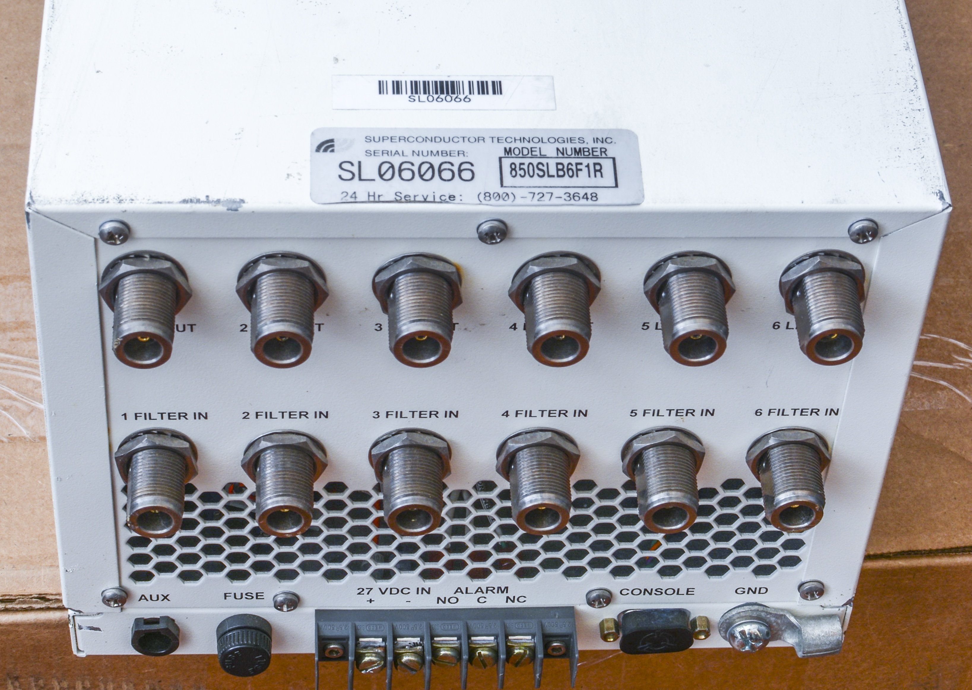
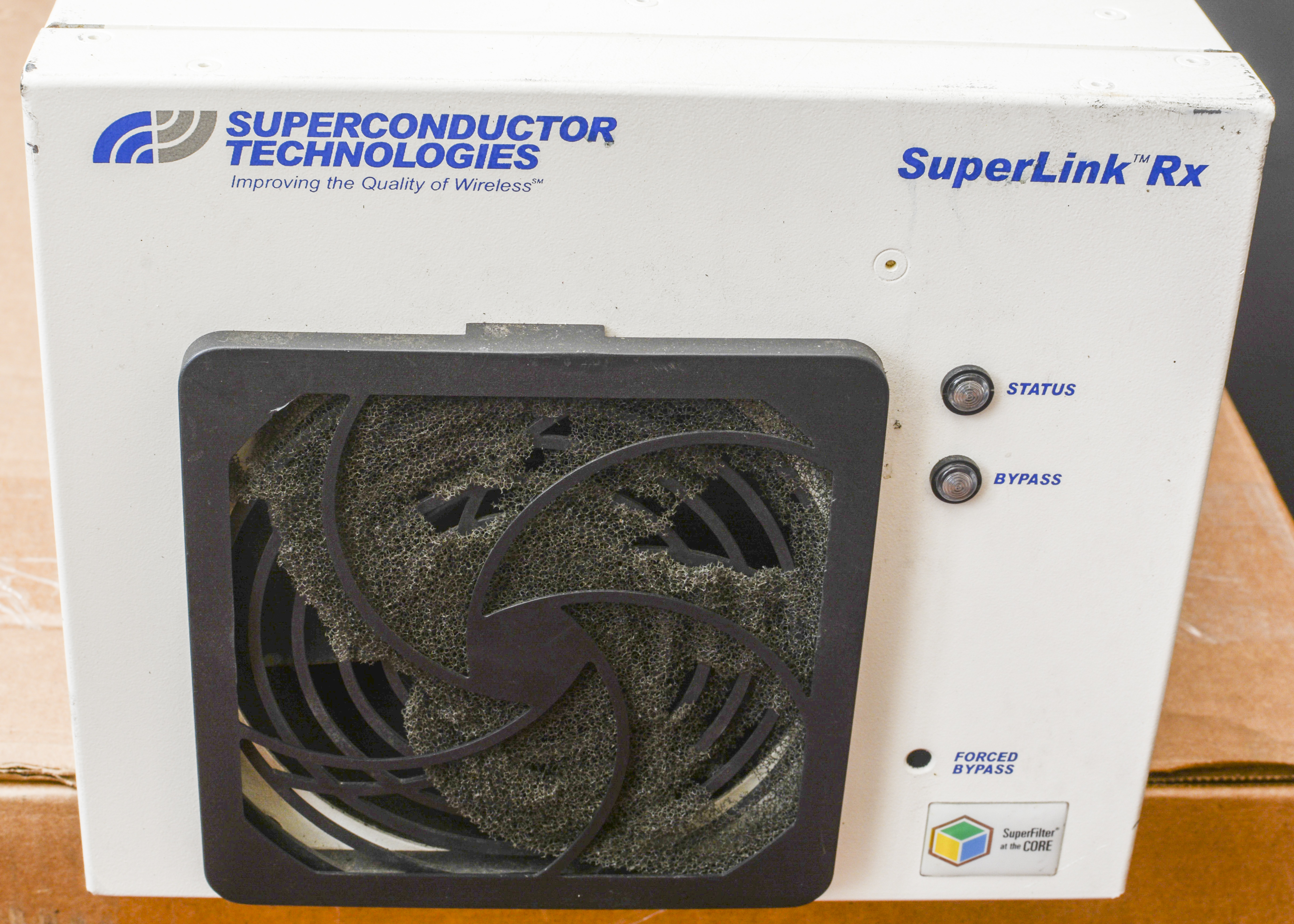
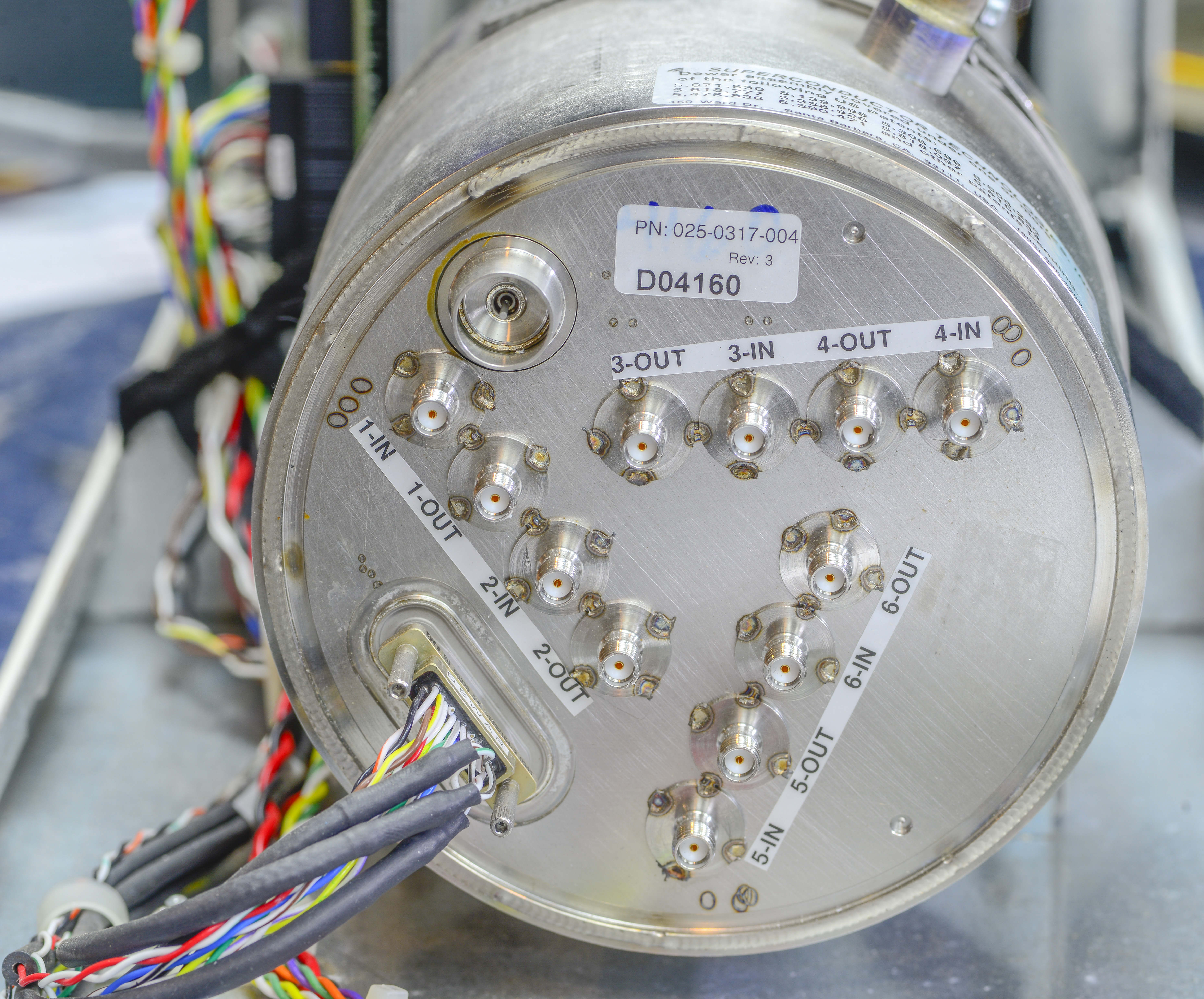
Image 5-6: Rear connections and front side fan filter, status LEDs.
Unit is quite heavy, so be sure to prepare enough space on the table when working with the device.
Teardown
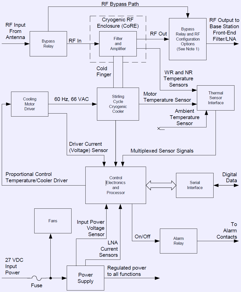
Image 7: STI SuperLink RX functional block diagram.
Since this unit is designed for telecom environment, it’s input power is DC +27 VDC. Internal power regulator generate all voltages for digital and analog control circuitry. Cryogenic cooler motor is driven by AC signal, synthesized on control PCBA as well. All key input and output parameters, such as voltages, RMS and real currents and duty cycle are monitored and logged by digital microcontroller. Multiple temperature sensors provide feedback about ambient, rejection and cold end temperatures for realtime PID-control.
Superconducting RF front-end is implemented in thermally and electrically isolated chamber, called Cryogenic RF Enclosure (CoRE). Bypass RF relays are mounted on chassis frame outside of cooled compartment to allow for RF path bypass (e.g. when system is cooling down or failed to operate properly).
Let’s crack the hood of the actual device open, and see what we dealing with.
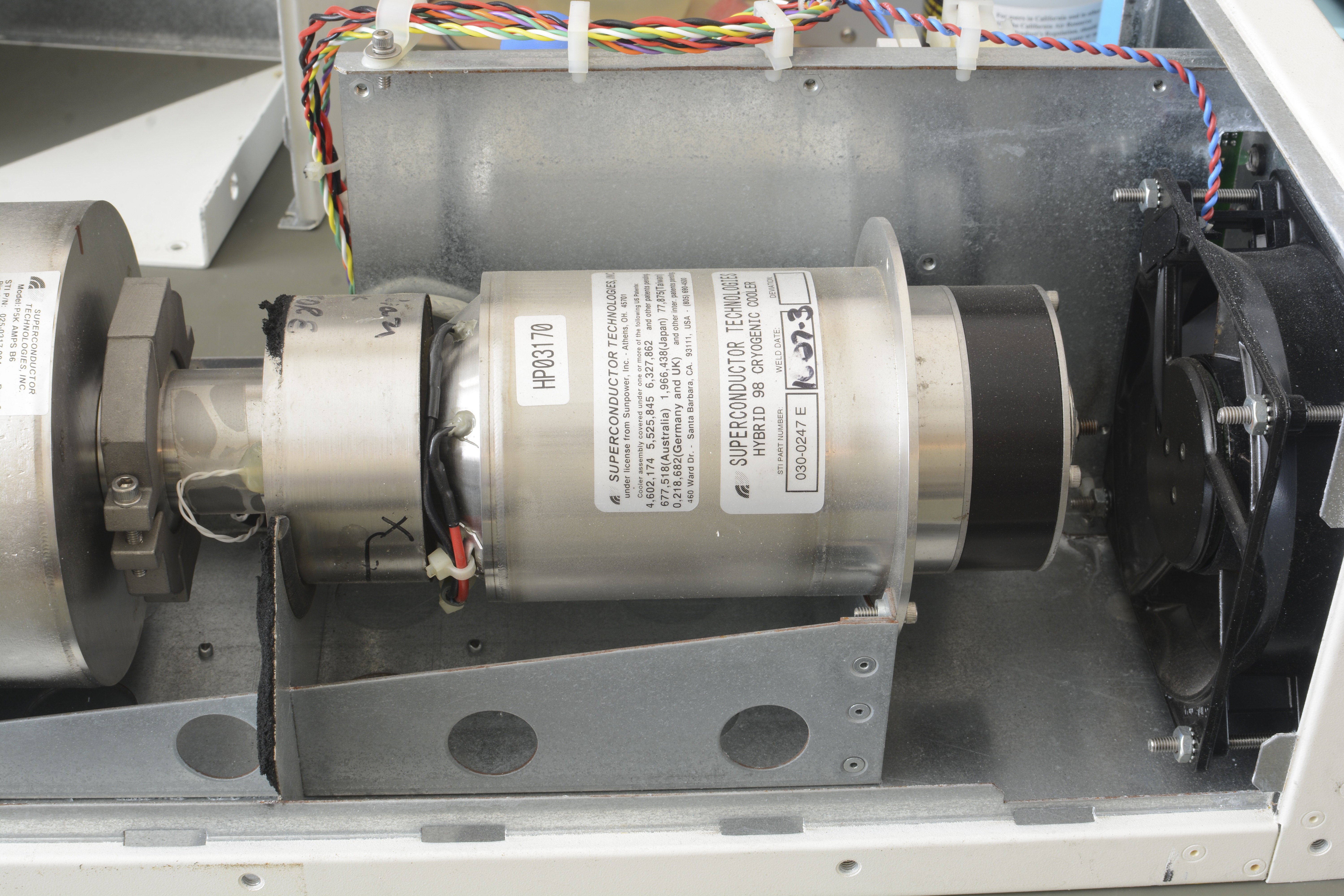
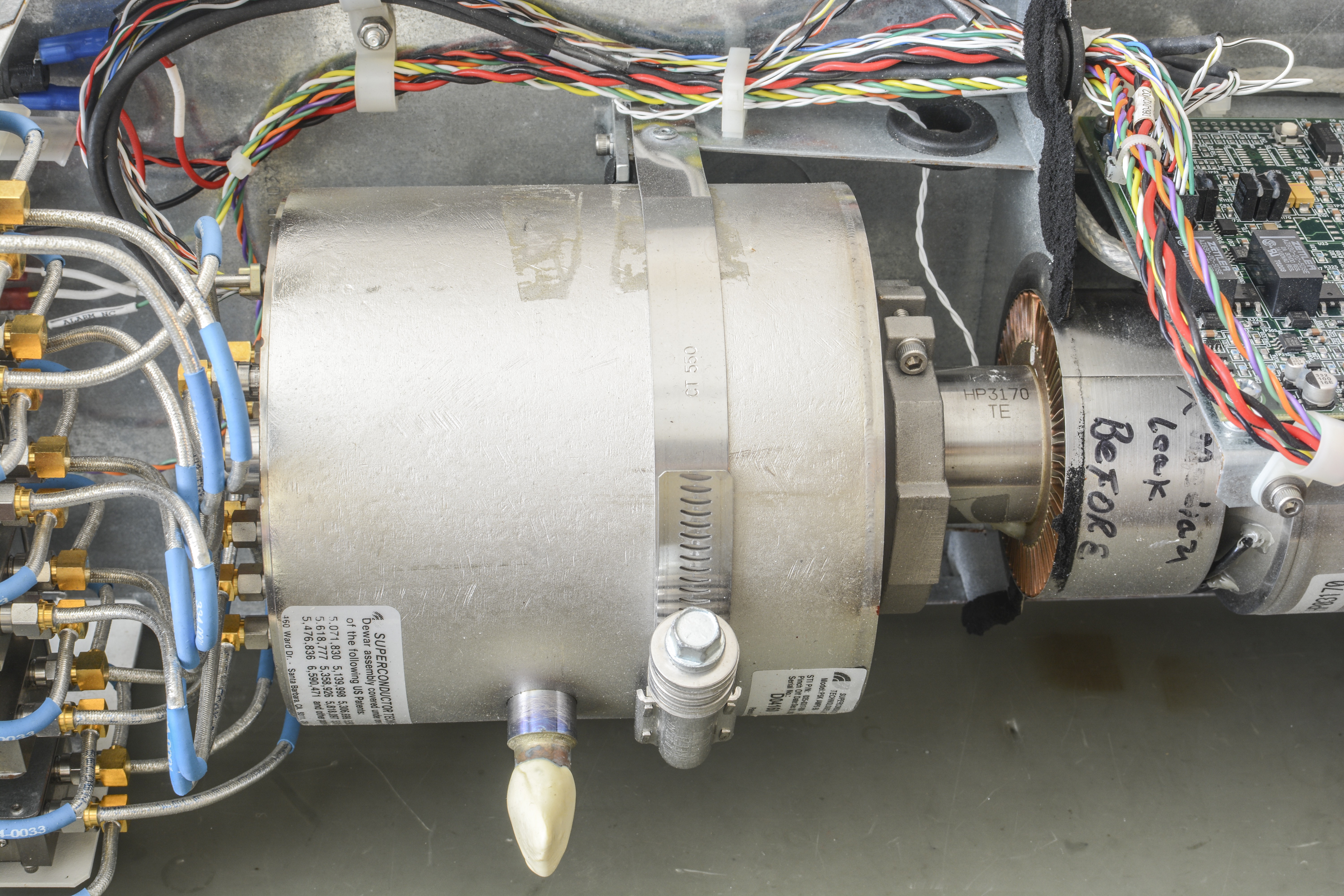
Image 8-9: Cryocooler assembly and RF cryocooled isolated chamber (left to right).
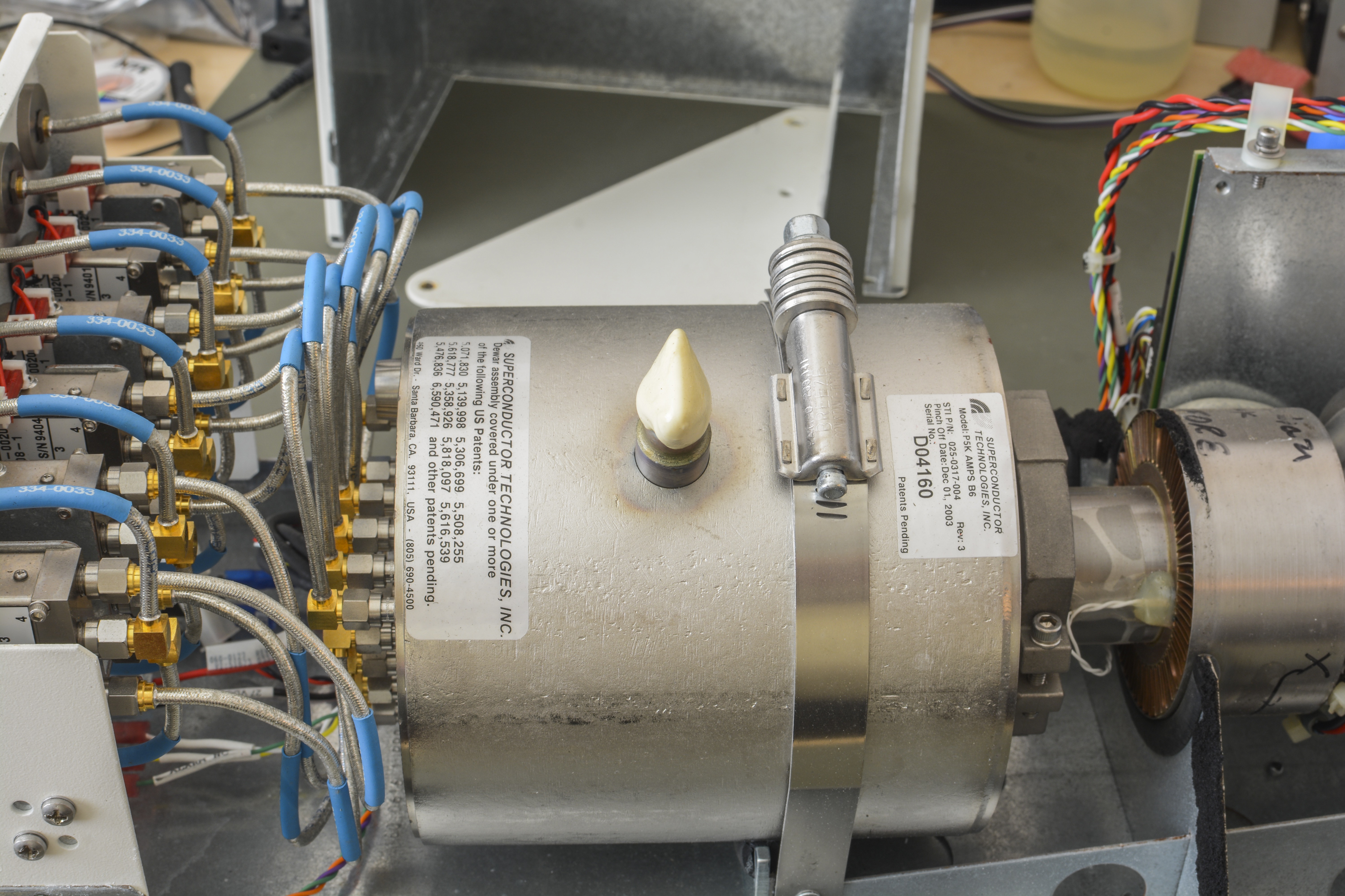
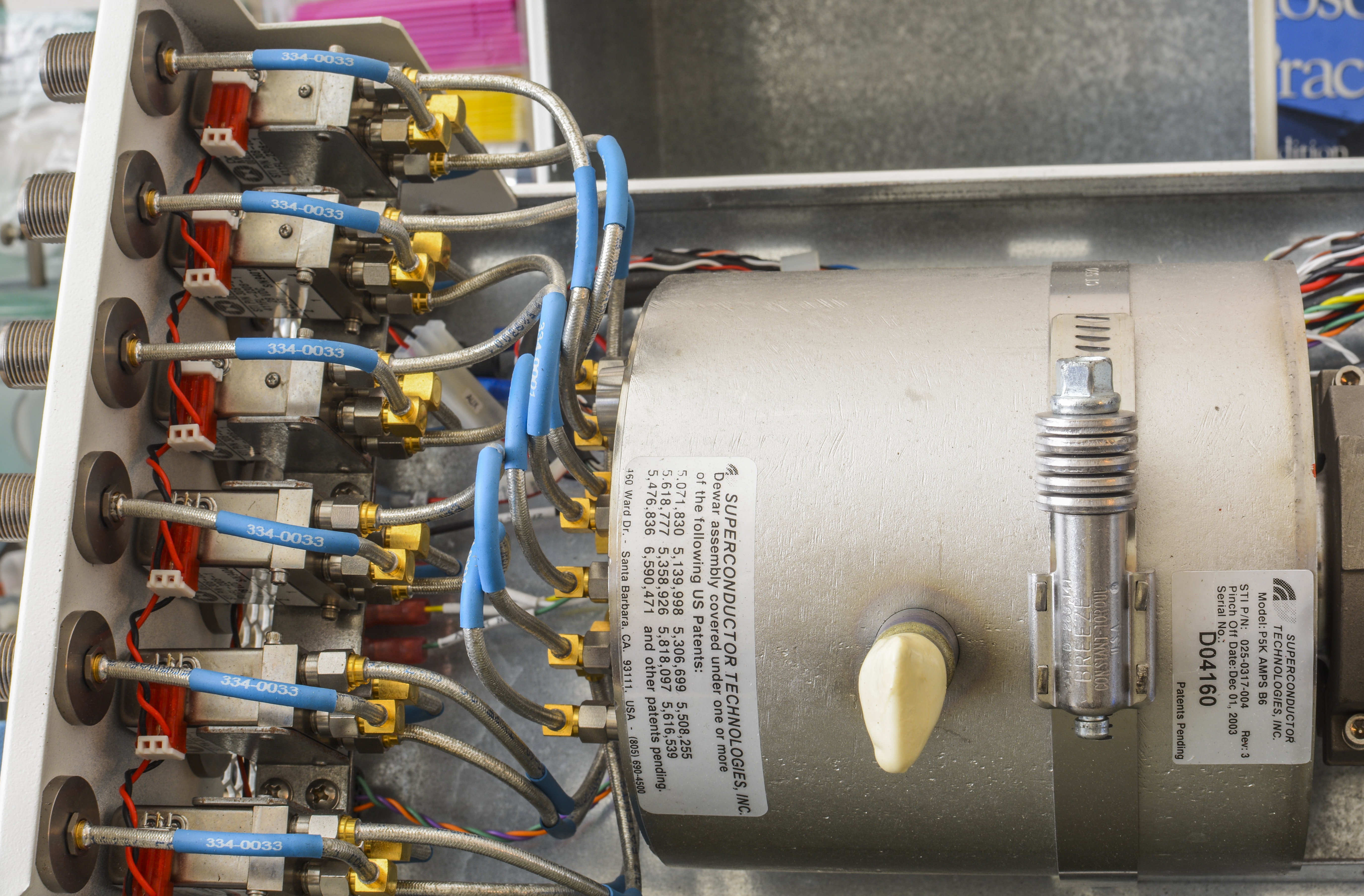
Image 10-11: Overview on labels and external RF switching and N-type connectors.

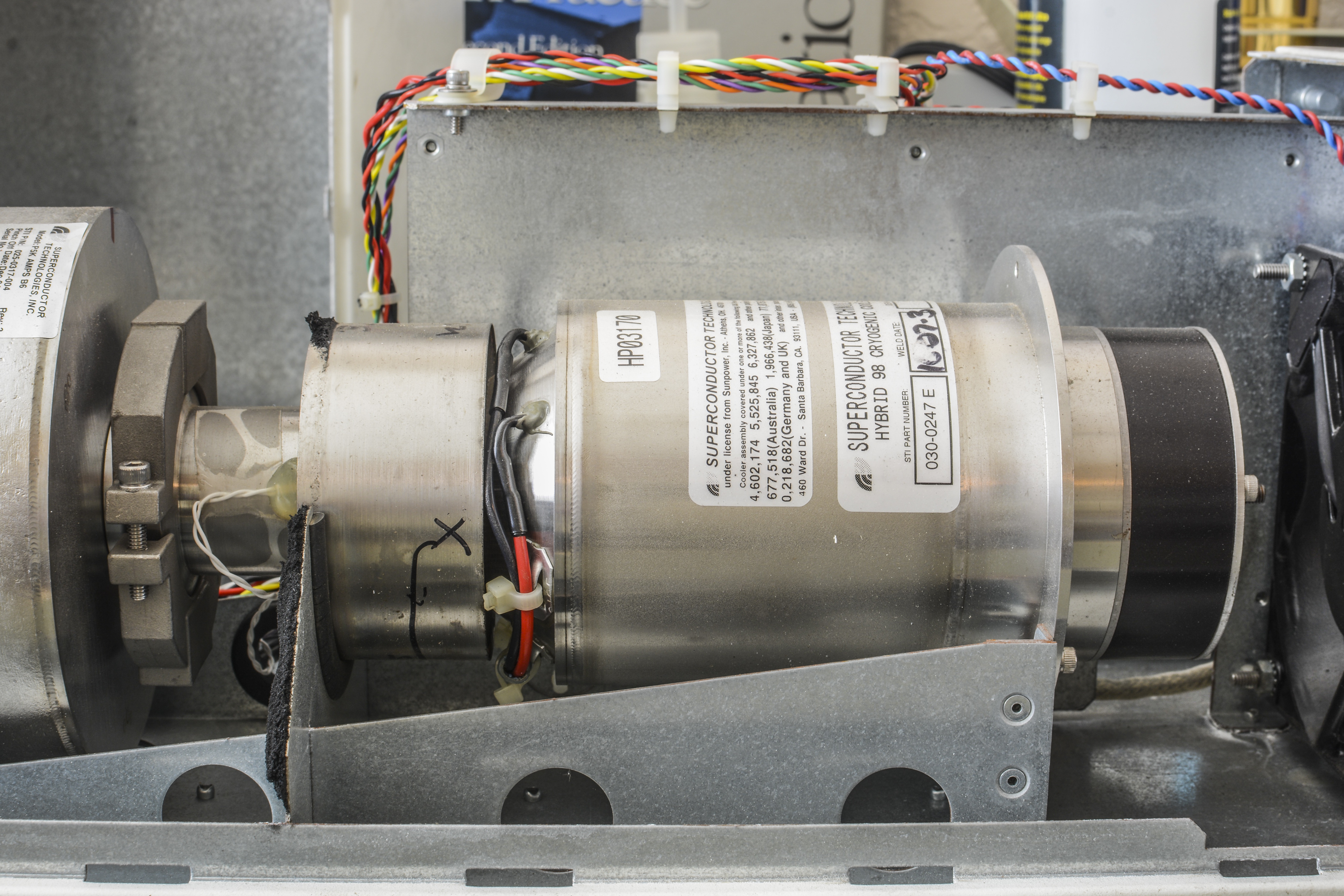
Image 12-13: Side view on both metal assemblies.
Stirling engine cryocooler
In 1816 Dr. Robert Stirling patented power engine which worked on process that became known as the Stirling Engine Cycle. The external engine was characterized by a power piston, a displacer to move the enclosed working gas body between the hot and cold ends and a regenerator, placed between the hot and cold ends of the displacer cylinder. The end result was enhanced operational efficiency of the engine, leading to a reduction in the amount of energy needed to heat up the working gas.
The Stirling refrigerator’s most basic schematics consist of the piston and displacer. According to the ideal gas law, during the repeated gas expansions the heat is repeatedly absorbed by the expanded gas from its surroundings, making it colder. Analogously, during the repeated gas compressions the heat is repeatedly ejected from the compressed gas into the atmosphere. Proper timing of the compression and expansion phases allows for lifting the heat at the cold side, transporting it through the regenerator to the hot side and ejecting it into the atmosphere. For over two centuries this basic concept of the Stirling engine has remained unchanged, while advances in regenerator materials, seal technology and flexure bearing designs have made the Stirling engines highly efficient, reliable and robust machines.
Stirling-process Cryocoolers can come in various sizes and cooling power capacity ratings, from small 2-5W units to multiple kW beasts, with operating temperature ranges of 10 – 40 K (dual-stage designs) to 40 – 150 K for single-stage designs.
Superconductor Technologies Sapphire cryocooler is using single-stage design to provide heat lift from vacuum-insulated chamber with RF components into ambient atmosphere, cooling down cold finger to extreme temperatures. The Sapphire Cooler use compressed helium gas to maintain the insulated RF assembly chamber at an operating temperature of about 78 K (Kelvin, or -195 °C). The compressor and cold finger are fully integrated into a single self-contained hermetic unit. The cooling motor driver controller provides drive and maintains a constant temperature. Temperature sensors in both the chamber and the cooler provide for constant temperature monitoring of the system by the software.
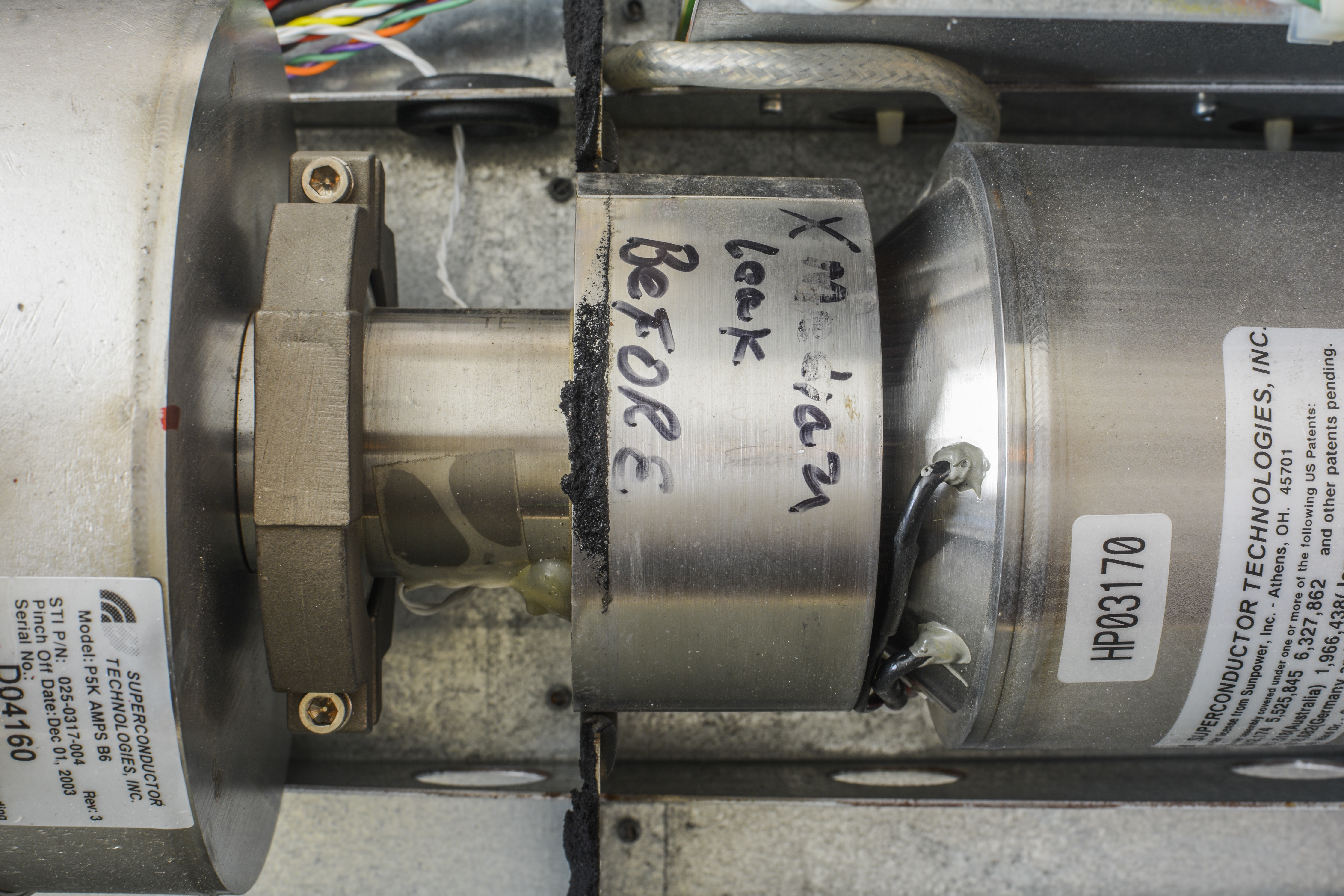
Image 14: Is that “Medium leak before” hand written label?
That label bit alarming. Let’s hope that it does not mean that cryocooler had all helium leaked. Such thing would turn this device into useless piece of metalwork.
Cryocooler construction and concept of operation covered by patent US6327862 in great detail. This design provides about 5.7 watts of heat lift with 77K (-196 °C) cold finger temperature at 100 W of input electrical power.
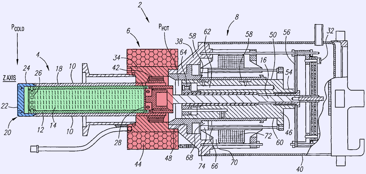
Image 15: Construction drawing of the cryocooler from patent US6327862.
This cooler electrical compressor operates at 66 VAC, 60 Hz, which is generated by power convertor on controller board. Overall unit is powered by +27 VDC, which is received at the external POWER terminal block connections, located on the rear panel of the STI SuperFilter. DC power is routed through a 12 A fuse (or 10 A on some SuperFilter models) to the fan and the power supply module.

Image 16: Stirling cycle phases. Courtesy of Stirling Cryogenics .
Dewar assembly with superconducting LNA
RF filter in this unit is based on TBCCO-2223 superconductor (Thallium barium calcium copper oxide) is a family of high-temperature superconductors having the generalized chemical formula TlmBa2Can−1CunO2n+m+2. This superconductor material has critical temperature (Tc) of 127 K.

Image 17: Thermal sensor at the reject side of the cooler and view on hot side heatsink.
Few other cuprates are also widely used in high-temperature superconductor applications, such as YBCO and BSCCO. BSCCO superconductors already have large-scale application, for example, tens of kilometers of BSCCO-2223 electrical cables are being used in the CERN’s LHC particle accelerator.
Small YBCO superconductor blocks cooled by liquid nitrogen are also well known in popular videos and experiments using magnets, to demonstrate magnetic levitation.
Control and power board
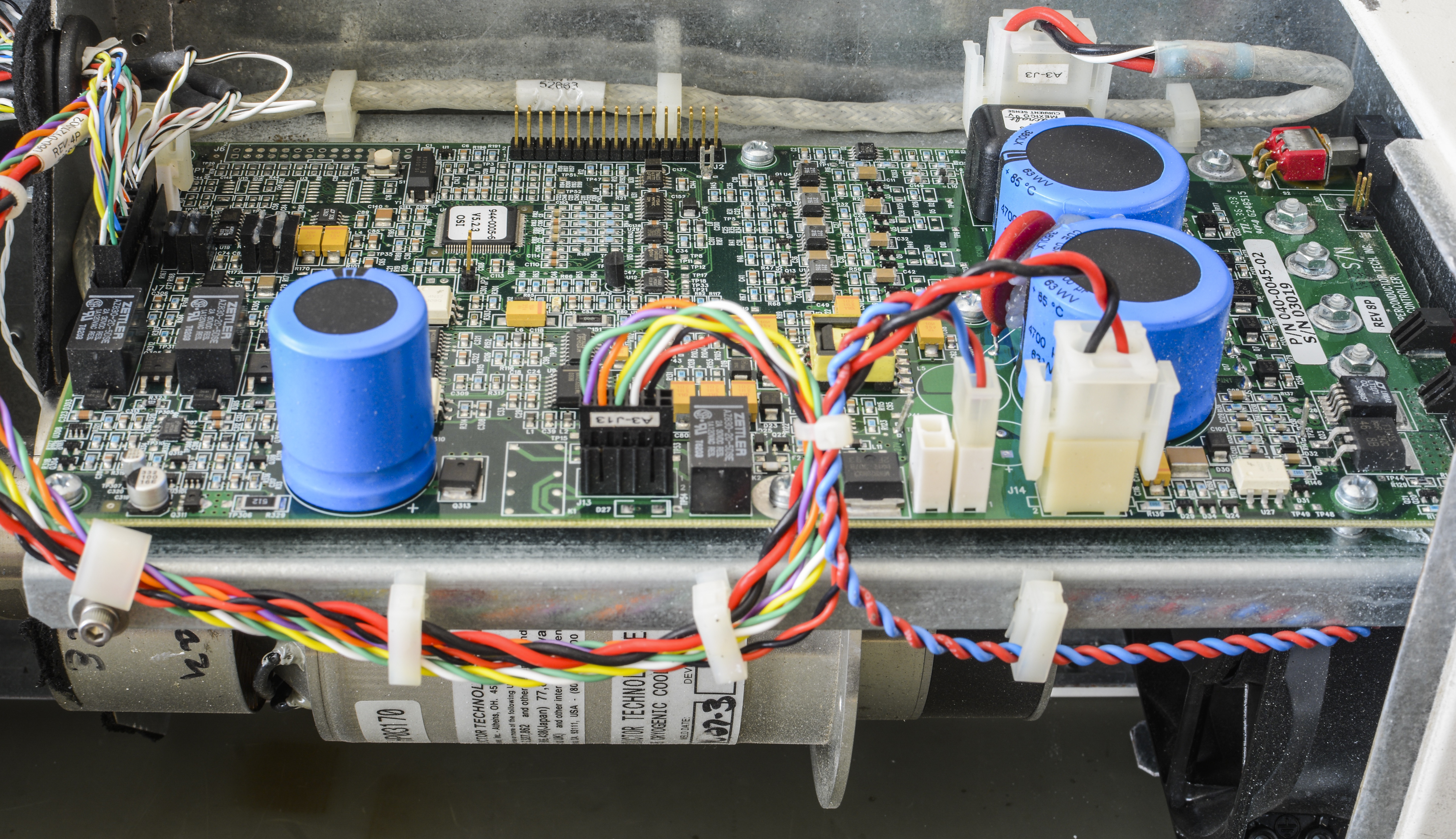
Image 18: Control and monitoring electronics.
Mainboard with control and power convertor circuitry is located on the side of chassis. Controller in TQFP package have label 944-0005-6 V5.2.3 which likely means firmware version.
There are bunch of logic chips nearby, such as U13 16-Kbit SPI EEPROM 25C160, few U12,U17 Texas Instruments LMC6482 R2R ultra-low input current (<20 fA!) operational amplifiers, U22 LTC1262IS8 30mA 12V DC-DC regulator, U19 AD8552 which is zero-drift RRIO dual opamp.
Output power stage that drives cryocooler compressor motor is controlled by Linear LT1171 that have wide input voltage range from 3V to 60V and capable to provide 2.5 A of switching current and can be externally synchronized to desired operating frequency. Pair of 4700 µF × 63 V capacitors from Cornell Dubilier provide output signal filtering.

Image 19: Close view on electronics PCBA.
There are even six Vishay Precision Group metal foil S102-series resistors in rectangular black epoxy packages, standing next to DAC. Good old MAX3232 also here, to provide level conversion TTL-CMOS for RS232 port.
Control application features
STI have Java-based application for these SuperLink units that allow monitoring and controlling all key parameters of the cryostage. It was available for download from STI some time ago, but since company was made aware of non-designed use of these cryocoolers by DIY makers (mostly to make homemade setups to condense air/nitrogen), they removed application from site. We got a copy for use before that happened, so here it is.
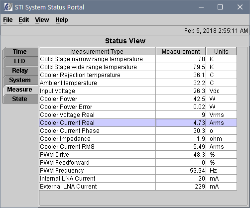
Image 20: STI System Status Portal main menu when everything running.
Cryocooler first test
First thing to do, is to verify that cryocooling assembly is still functional and have no problems reaching operation temperature points.
STEP 1 – Connect interface cable to WinPC.
Connect Windows-based PC terminal RS232 cable to SuperLink RX. To communicate with the controller board, STI provides two programs you need to install on your PC: Java Runtime Environment and the System Status Portal control software. The Java Runtime Environment is required for the System Status Portal to operate properly. If you already have the Java Runtime Environment on your PC, you do not need to install this program. This Application will allow to control and monitor all essential Cryocooler’s operation data using just single serial Interface to Terminal application on PC.
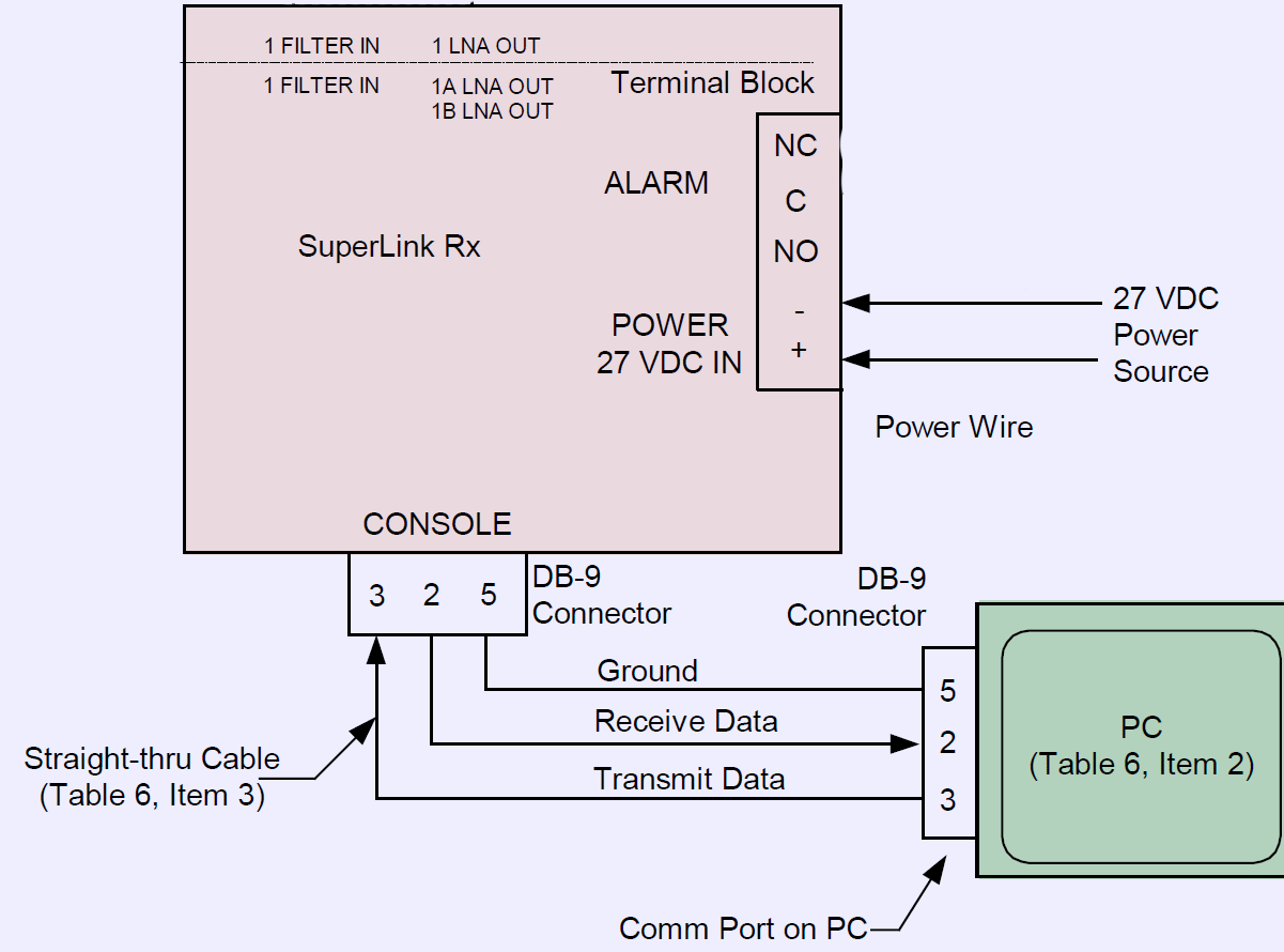
Image 21: Connection between RS232 port on PC and SuperLink RX unit.
STEP 2 – Find suitable power supply and connect it to SuperLink RX.
Run the power wire from DC power source output to the terminal block on the rear panel of the SL Rx. If DC PSU have sense lines, connect them only at the SuperLink RX terminal block, following the polarity (Sense+ connect to Force+, and Sense- connect to Force-). The terminal block connections are labeled 27 VDC IN + and –.
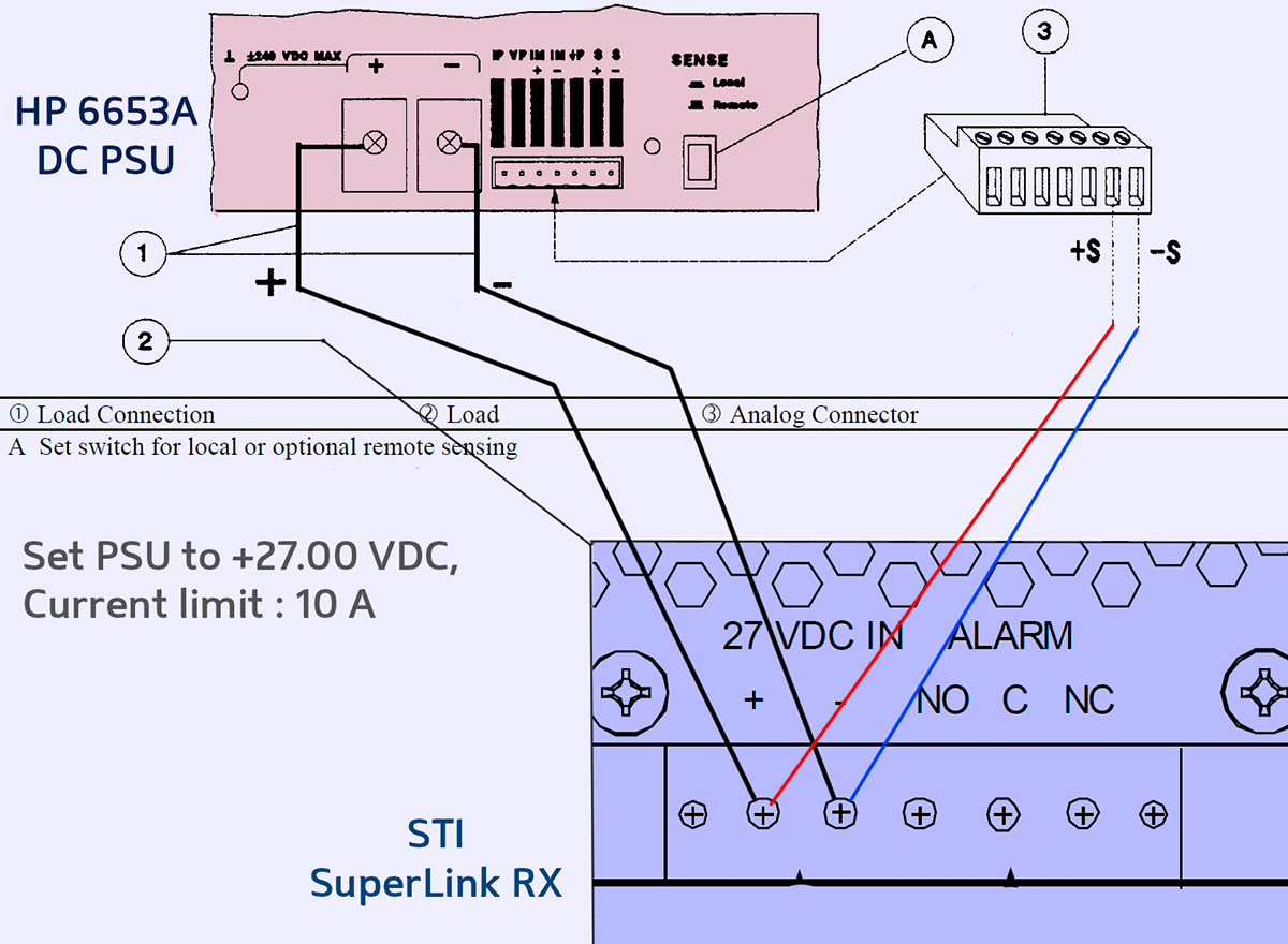
Image 22: Connection between HP E6653A DC PSU and SuperLink RX.
In our test run 500W HP/Agilent/Keysight 6653A system DC Power supply will be used to perform performance testing and functionality checks. This model is capable to deliver 35 VDC with loading current up to 15 A, which is well in margins of what required by SuperLink RX.
Set voltage sense to remote operation, if all four wires are connected correctly.
STEP 3 – Set the DC source to correct voltage and current limits for first test run.
Program HP 6653A to output +27.00 VDC and 10.00 A current limit. This is well in range of what SuperLink RX designed to take.
Check all the connections again, and if everything looks good, turn the DC Power supply output ON.
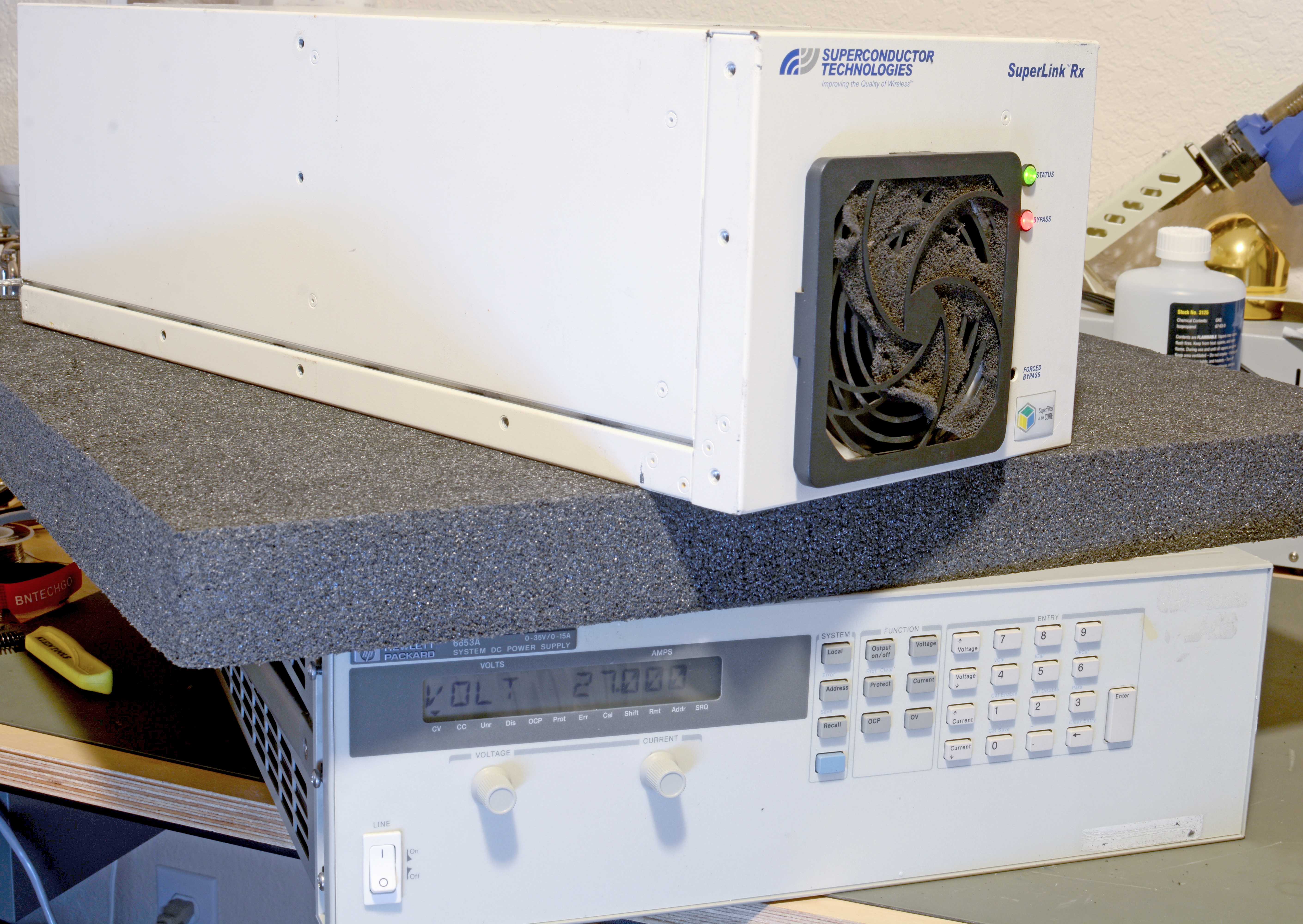
Image 23: Connection between HP E6653A DC PSU and SuperLink RX.
SuperLink RX controller board will gracefully start the cryocooler and front panel STATUS and BYPASS LED should be lit. When the cryogenic chamber has reached operating temperature at 78 K, the STATUS LED will be steady GREEN and the BYPASS LED will be off. Cooling down procedure should take less than 30 minutes, and no abnormal noises should be heard from the unit.
STEP 4 – Control software interface check and monitoring live unit telemetry.
We can attempt to read telemetry of the unit, while it’s running, by using System Status Portal control software. Click Communicate with Unit to establish communication with the SL Rx. Select the correct Serial Port to which unit is connected to establish communication, and then click OK.
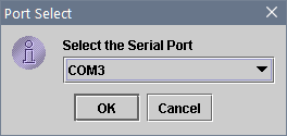
Image 24: Serial port configuration menu.
If there is communication error, check that all connections are correct.
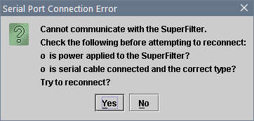
Image 25: Communication error if incorrect connections are made.
Sometimes with installation of new hardware/software system reboot is required, if there is connection issue.
STEP 5 – Check telemetry data once connection is established.
We had no problems to interface the cooler, using Windows 7 laptop and standard USB-Serial dongle cable.
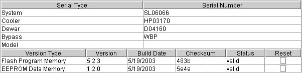
Image 26: Unit fault log and version information
No faults are reported, and firmware/EEPROM versions are matching the actual unit labels. Interesting to note build date, which is May 19, 2003.
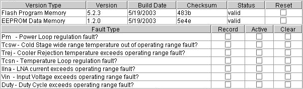
Image 27: Serial numbers for each key assembly in the SuperLink RX
Serial numbers are also matching up well, giving good confidence that control board and all components were not replaced and all calibration data is still intact.
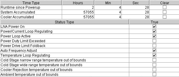
Image 28: Unit fault log and version information
History and current status are all reported as well. 57055 hours of running time translate into about 6.5 years of operation. Counting from the 2003, that would mean decommission of this specific SuperLink RX in 2009, 9 years ago.
STEP 6 – Cooling system telemetry verification
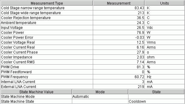
Image 29: Unit fault log and version information
After running everything about 1.5 hours temperature slowly creeped down to 83 K (-190 °C), which is close to the set point. Peak power was around 105-110 W, with cooler current near 8 A.
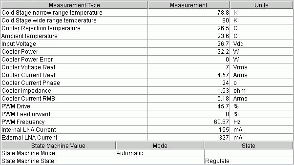
Image 30: Unit fault log and version information
Half hour more, and we reached the temperature regulation setpoint at 78.8 K (-194 °C), and power consumption dropped to about 33 W, while cooler current (RMS) dropped to 5.2 A.
So now I can happily confirm that cooling system and everything related to it works just fine. I’m not interested much in RF section, so that will be all removed and replaced with own assembly once the time comes. Back to the drawing board now!
Application allows temperature control set point in 20K window, with allowed range from 72.6 K to 92.6 K. However this is not a physical limitation of the Sapphire cryocooler, but rather software limitation. We will continue to explore wider temperature ranges with own Python-adapted software control over running parameters.
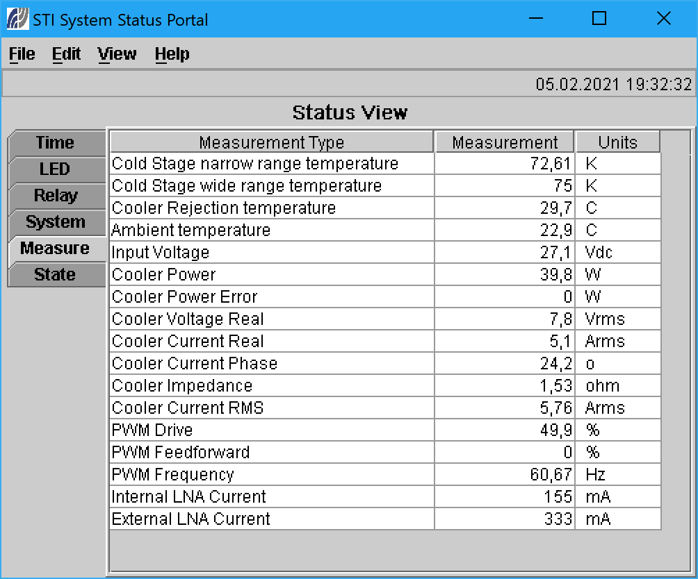
Image 31: Cryocooler operating at lowest allowable temperature setpoint 72.6K
RF filter + LNA benchmarks
With help of Keysight N9912A FieldFox RF 2MHz-6GHz network analyzer S21-parameter of superconductive filter + LNA were measured. Cryocooler was brought to normal operation mode at 77K temperature and shutdown cooling engine to avoid any effect on RF measurements. Filter+LNA port 1 was tested by power RF output relay to +28VDC level from Keithley 2400 SMU.
Setup and connections shown on photo:
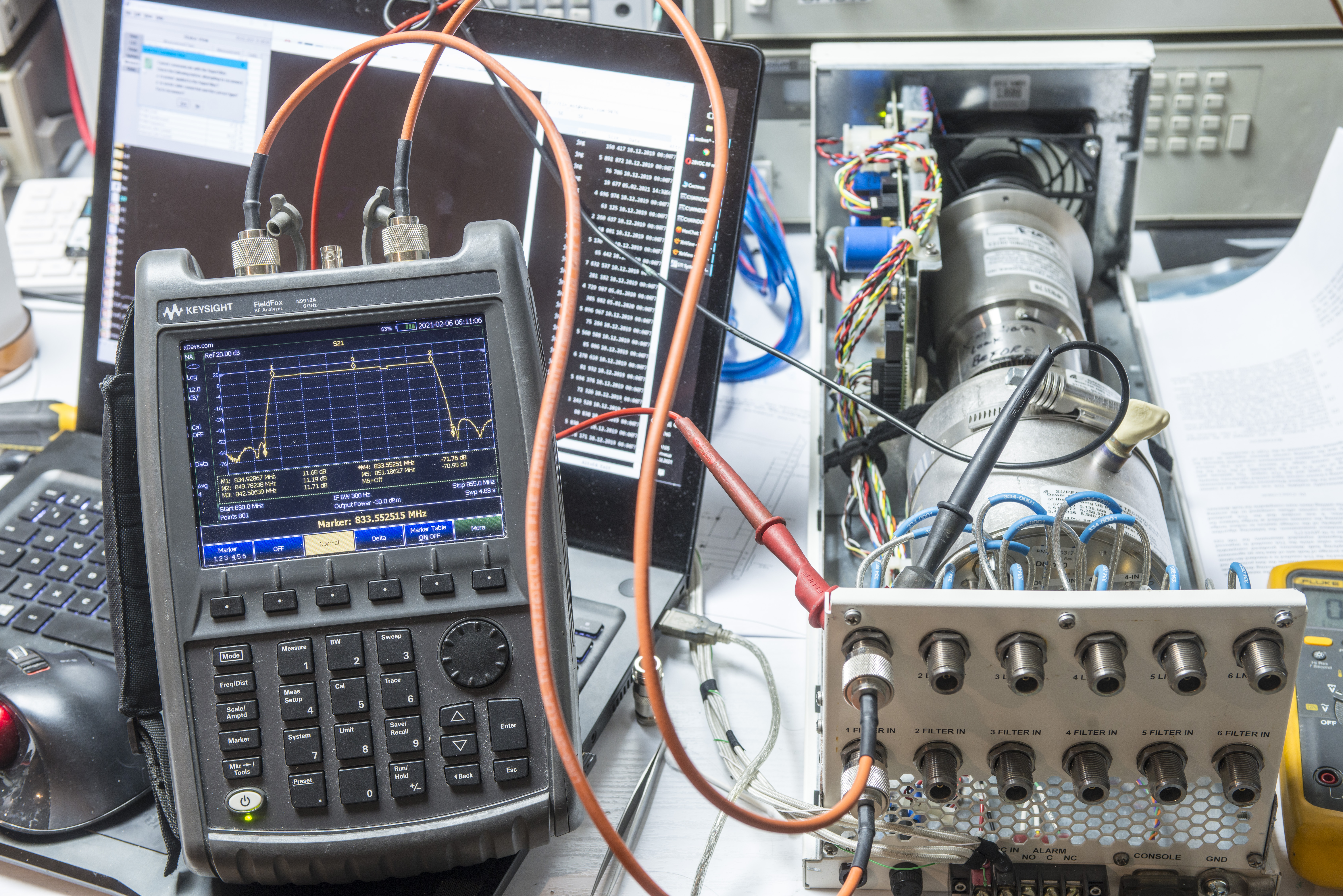
Image 32: SuperFilter RX 850 connected to VNA to measure S21
Benchmark results presented below. As temperatures in chamber were slowly climbing up, multiple measurements were taken to demonstrate change in the electrical/RF performance.
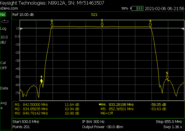
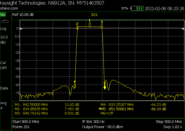
Image 33-34: Measurement at 77K (-196.1 °C) temperature, and wider frequency span
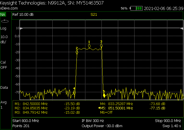
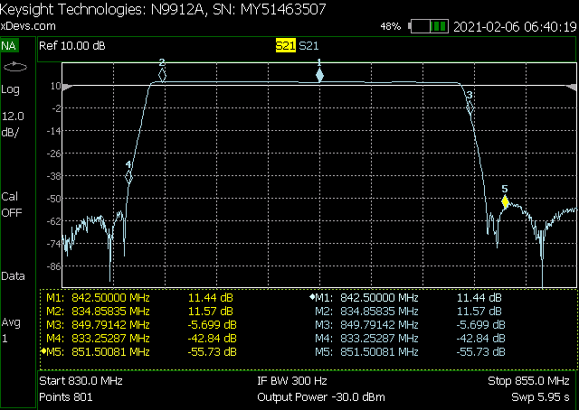
Image 35-36: Measurement at 77K, LNA power is turned off by RX850; LNA on at 83K
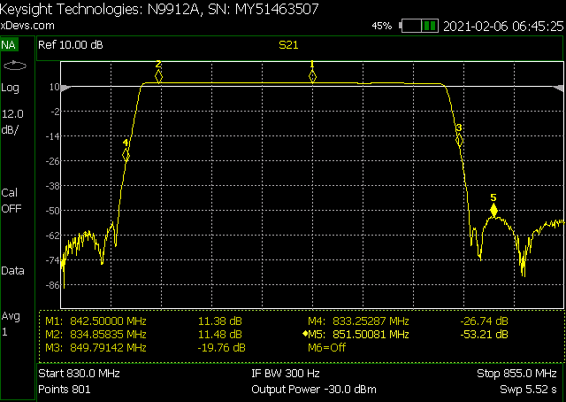
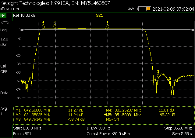
Image 37-38: Measurement at 85K and 91K (-188.1 and -182.1 °C) temperatures
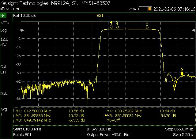
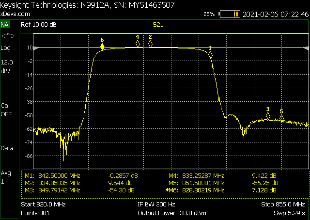
Image 39: Measurement at 96K and 98K (-177.1 .. -175.1 °C) temperatures
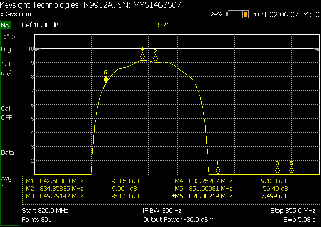
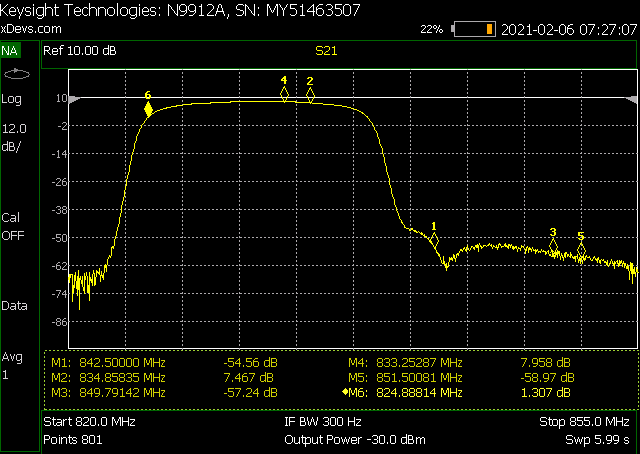
Image 41-42: Measurement at 99K (-174.1 °C), 1dB/div from 10dB point; 100K measurement

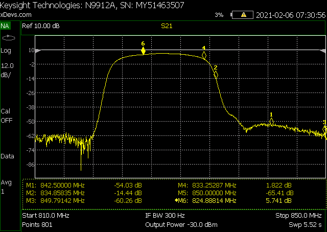
Image 43-44: Measurement at 100K, over wide frequency span; 101K measurement
Dewar assembly teardown
As I don’t have actual use for 834-849 MHz BPF filter, it is more interesting to take Dewar vessel apart to learn about practical design tricks and methods used in cryocooled electronics assembly. As usual process will be documented below with ultra-high resolution images to reveal all little details.
First Dewar detached from cryocooling engine. All RF connections and rigid coaxial cables are removed. Release strap and with removed rear chassis wall whole Dewar assembly slides out easily.
Be careful not to bend heatsink on cryocooler’s rejection zone.

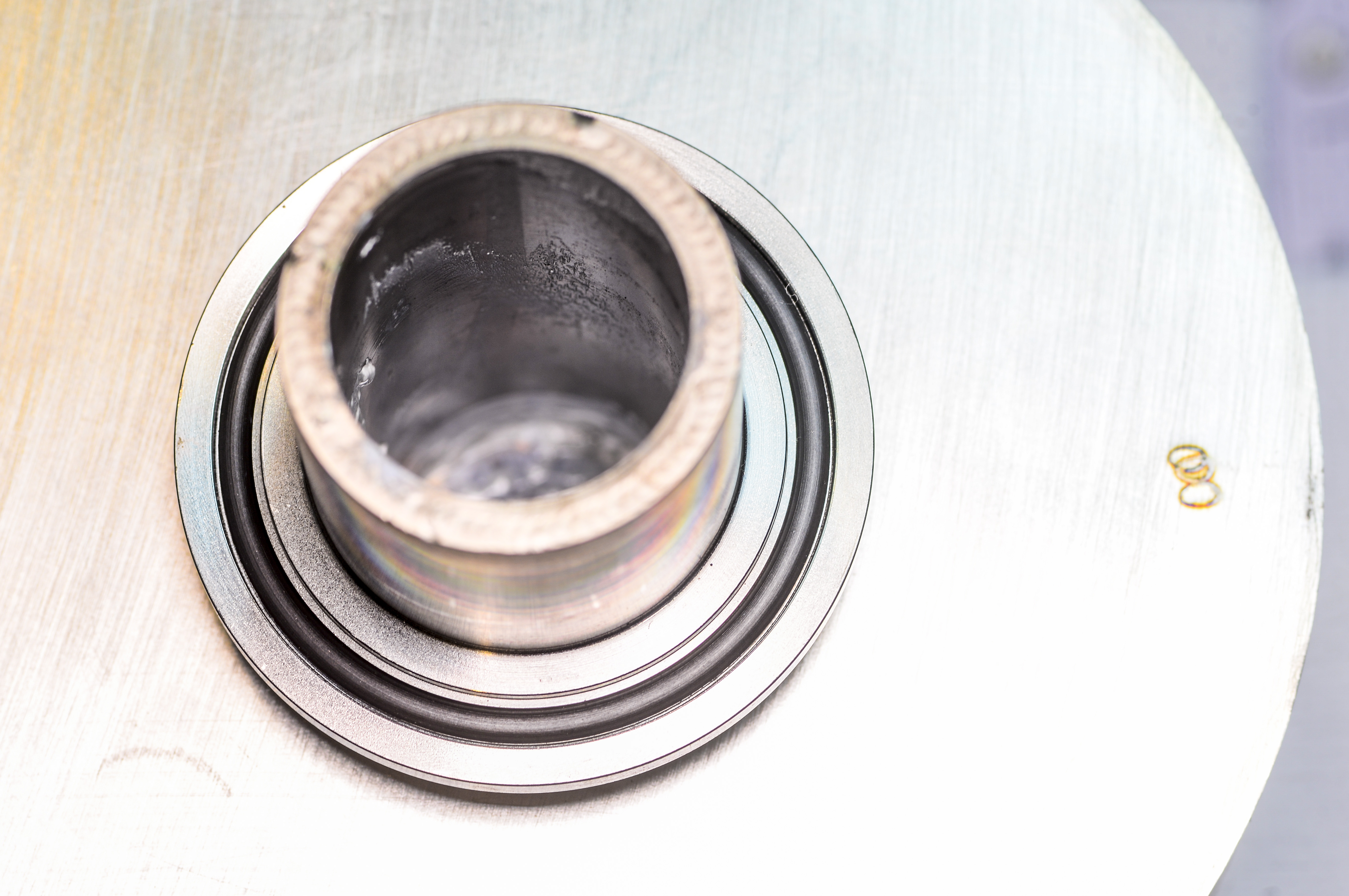
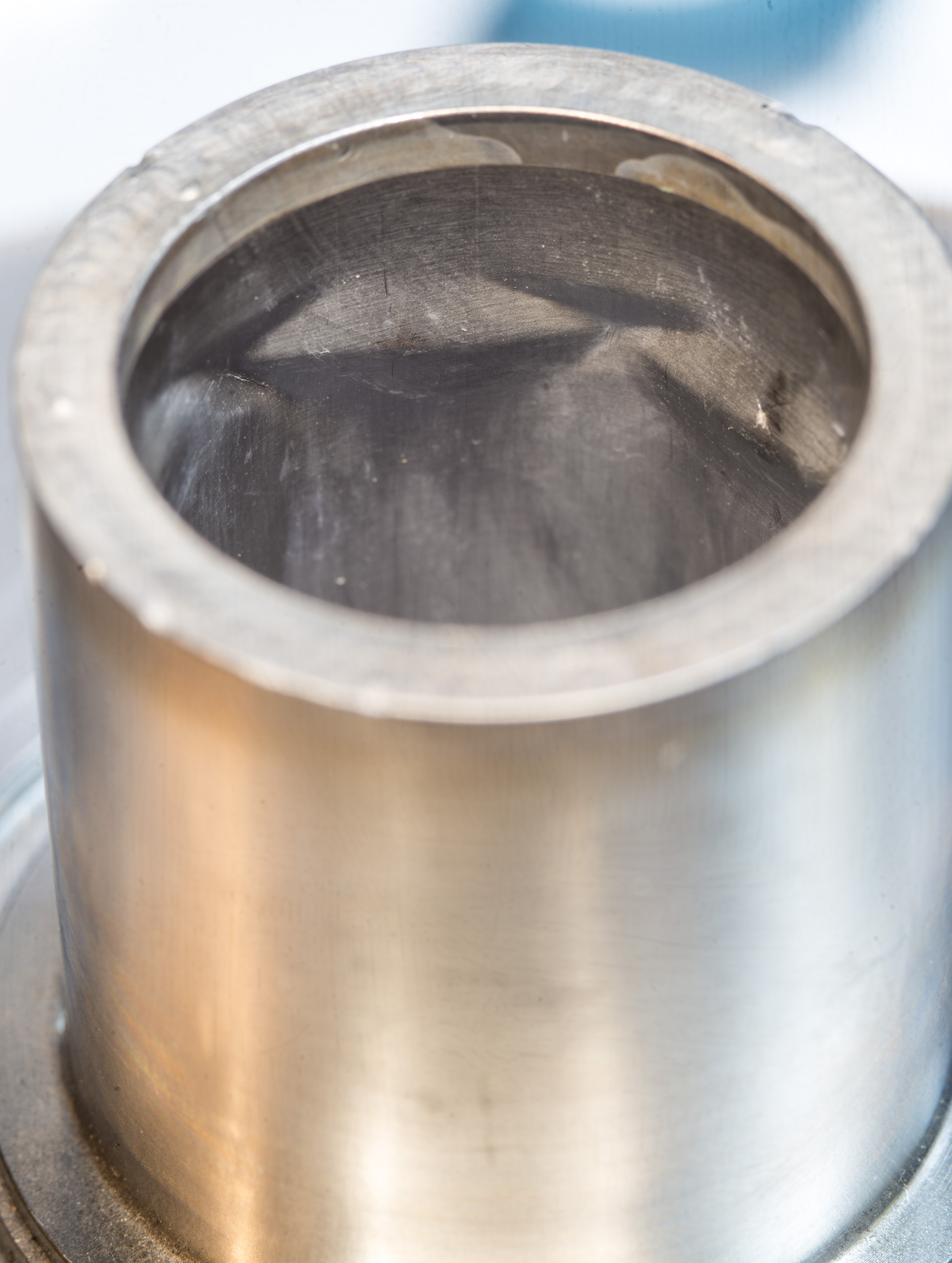
Cold finger is now visible.
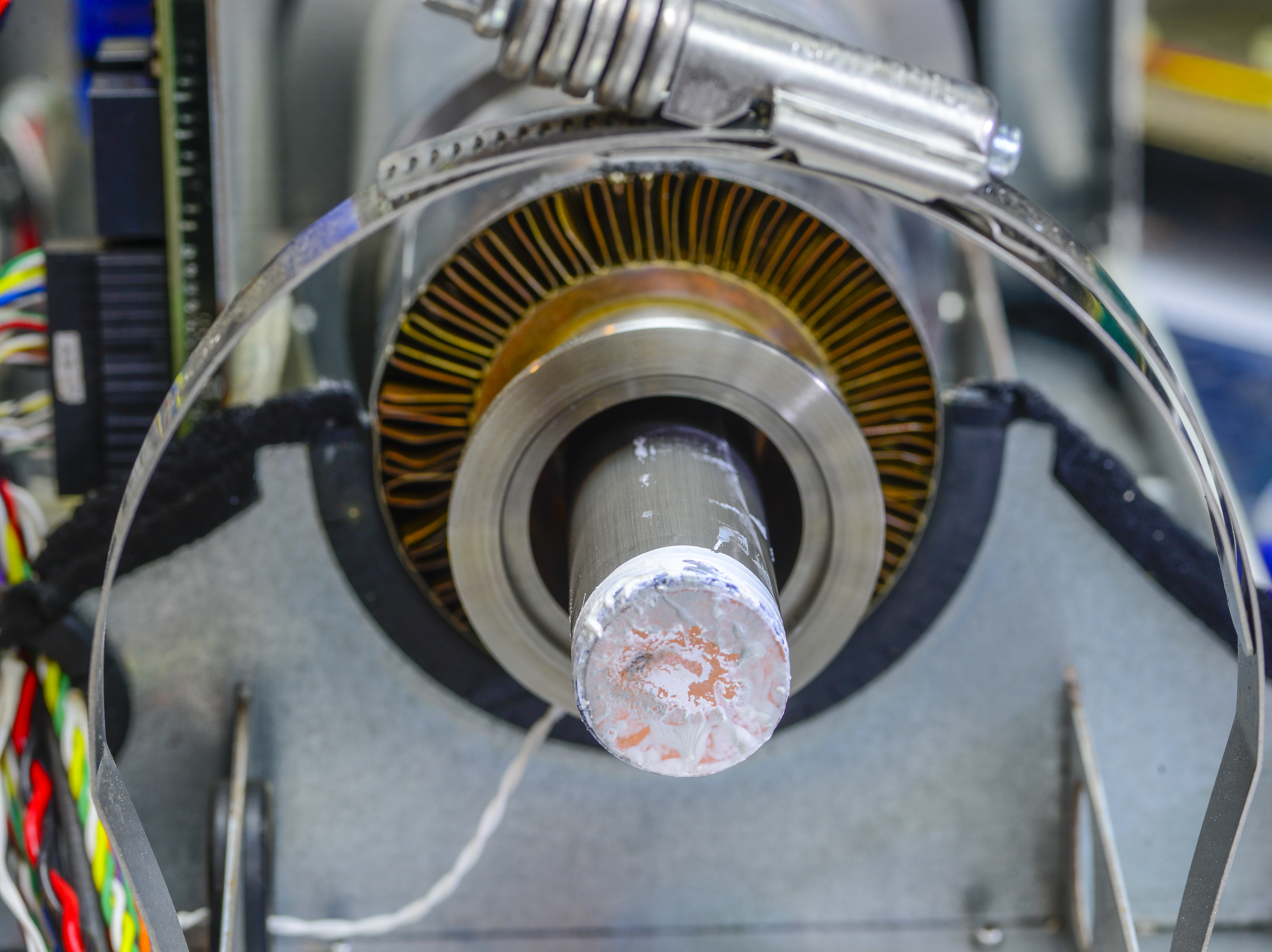
Dewar has flange with rubber O-ring to provide airtight coupling with cold finger. There is no gas or vacuum in there, it’s just a measure to avoid condensation and corrosion over time.
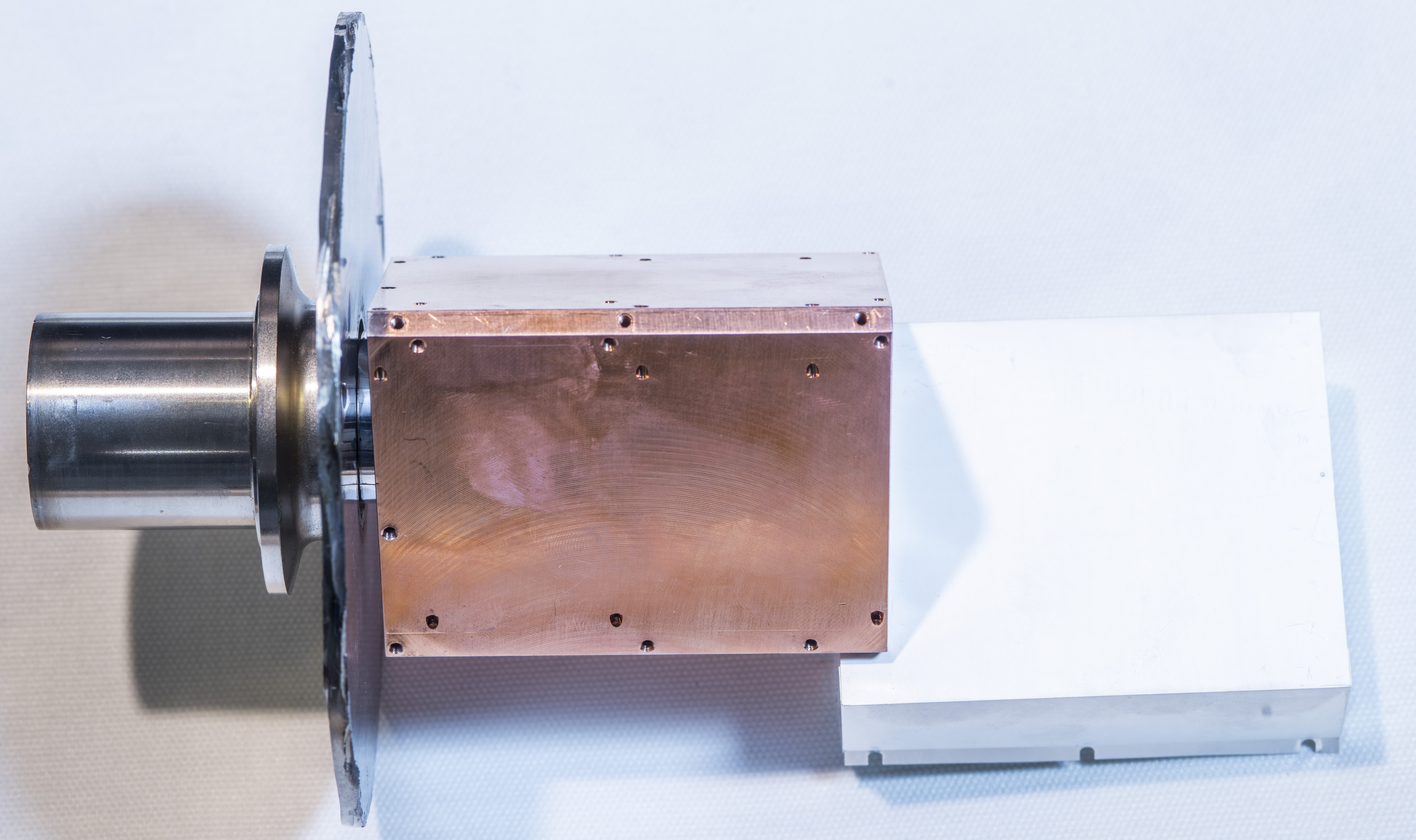
Now we can put cryocooler and STI chassis with electronics apart and focus on Dewar block.
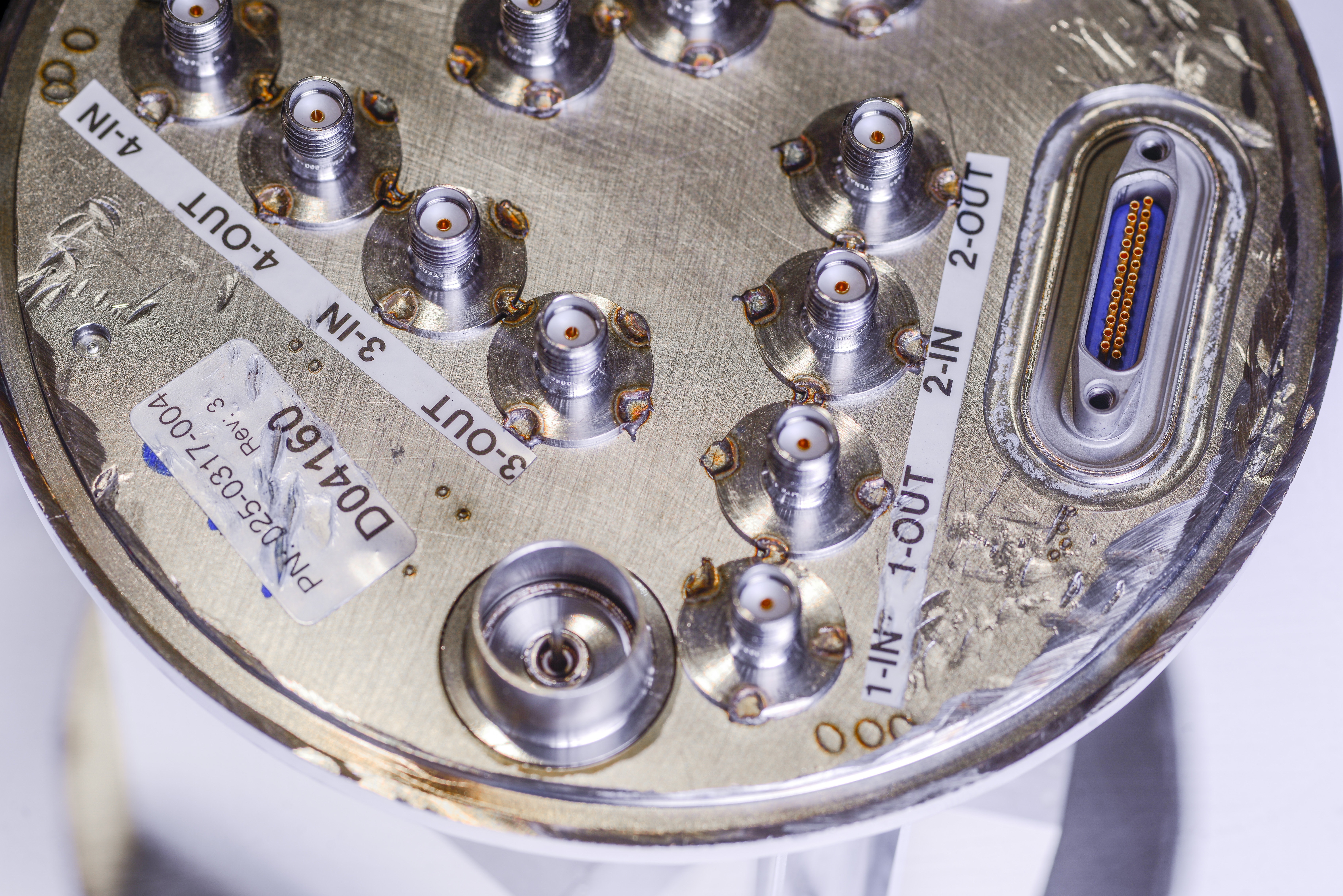
Take a close look on micro-D 25 pin connector. Such vacuum weld-seal connectors are very expensive, often $500+ USD a piece. Even “usual” micro-D connector may cost nice $305 USD. You don’t see such connectors on usual commercial equipment.
First step is to open vacuum port. Hardened epoxy is cracked with gentle hammer tap, and copper tube was open to let air in.
Now welded stainless steel edge was grinded away with angle grinder. It was messy and noisy action for about an hour with quite a bit of smashing and hammering! Again, I did not care much about reusing this assembly in future, so went a bit medieval on it.
… 2 hours later …
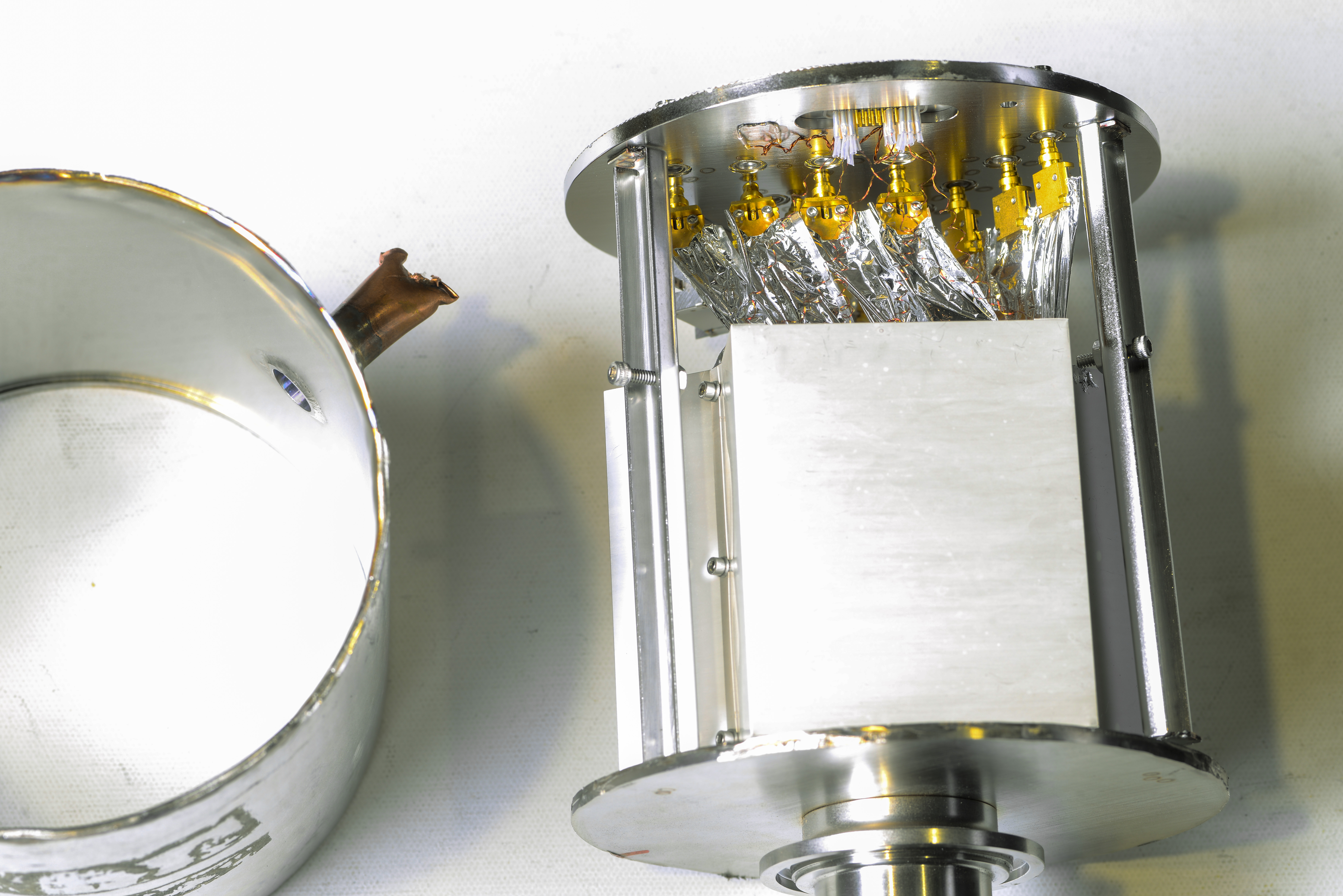

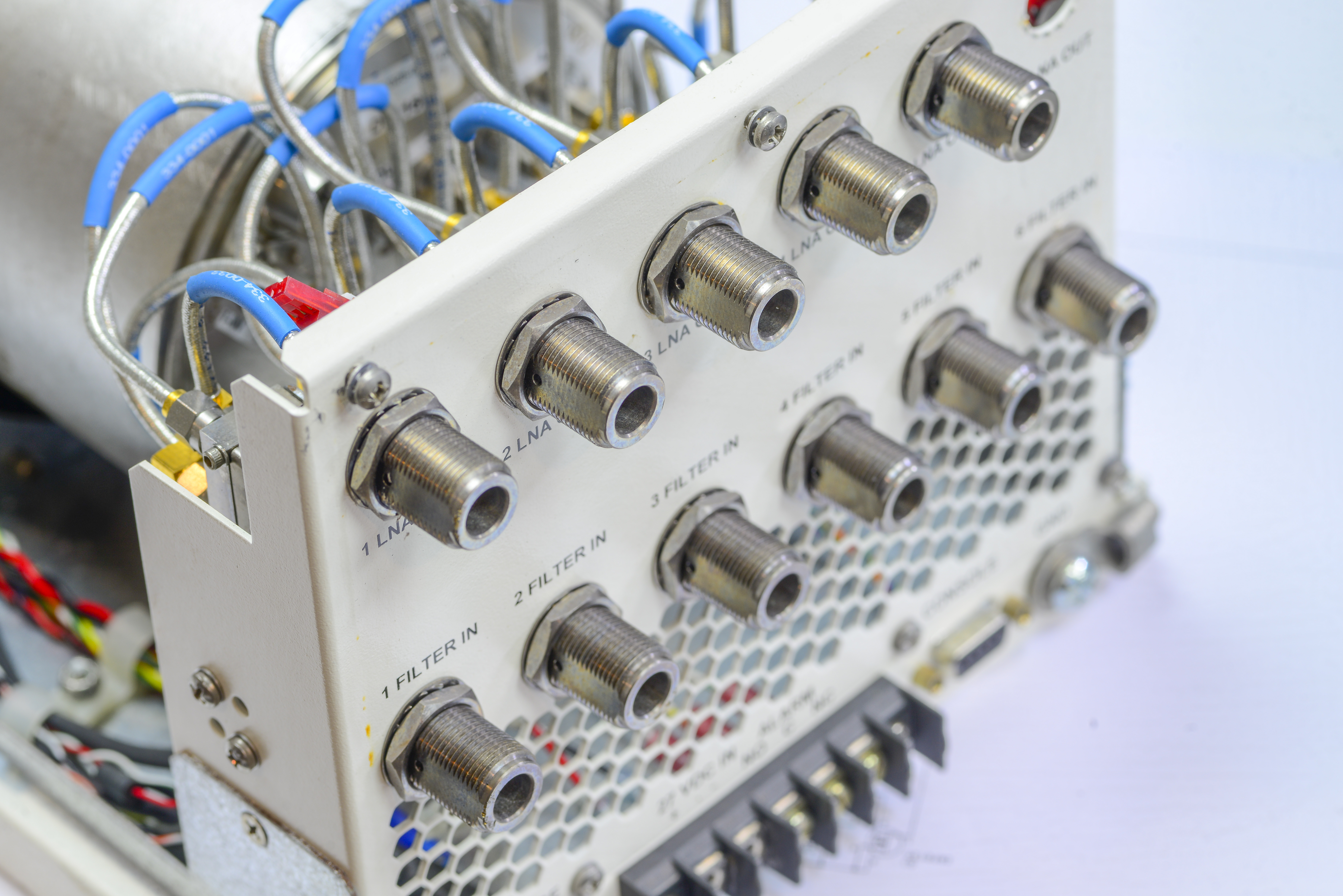
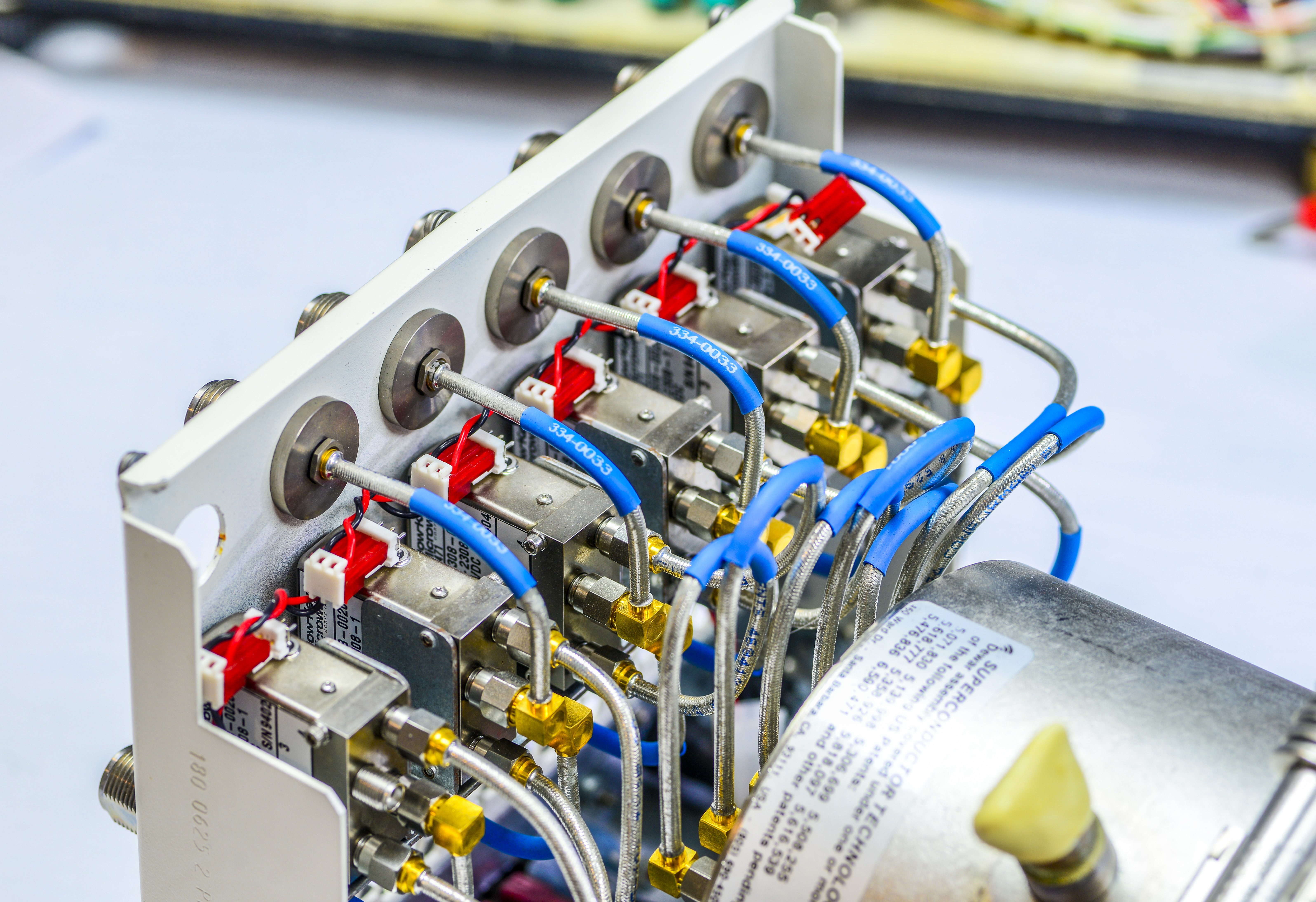
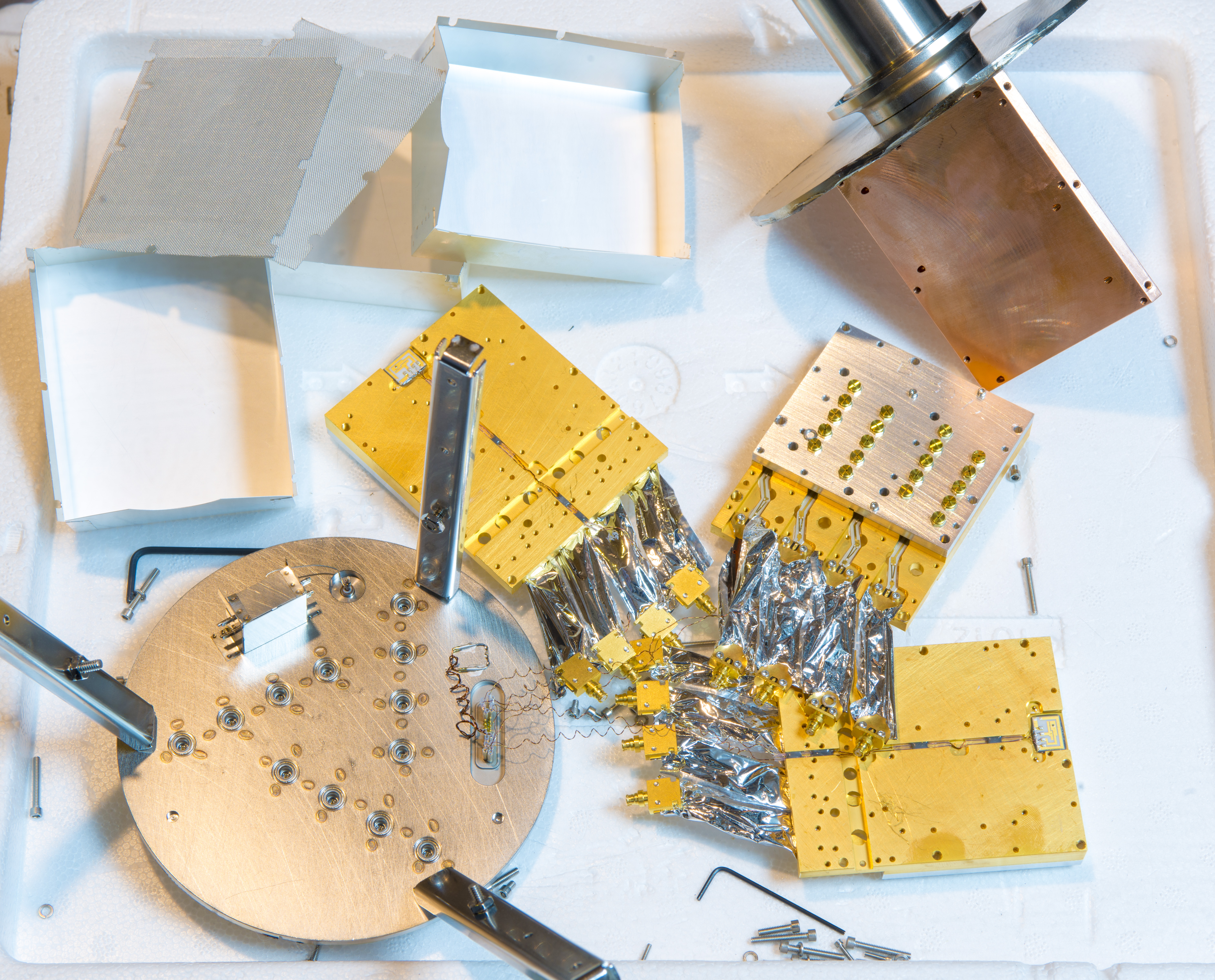
First spot – RF lines with SMC-ish type miniature connector that plug into vacuum-sealed SMA ports on top lid. Why they are all wrapped in aluminum foil? That is heat and RF shielding to reduce thermal leaks from cooled block to room temperature outer massive steel wall of the Dewar.

The filter blocks also include thin metal radiative heat shielding to minimize heat loading of the cryoelectronic module via thermal radiation from the Dewar walls, which are at ambient temperature. This help to minimize the heat load to the cold head and ensure good regulation. Same approach used with RF cables to and from the cryoelectronic modules. These techniques are not unique to STI design but are standard practice in cryogenic equipment.

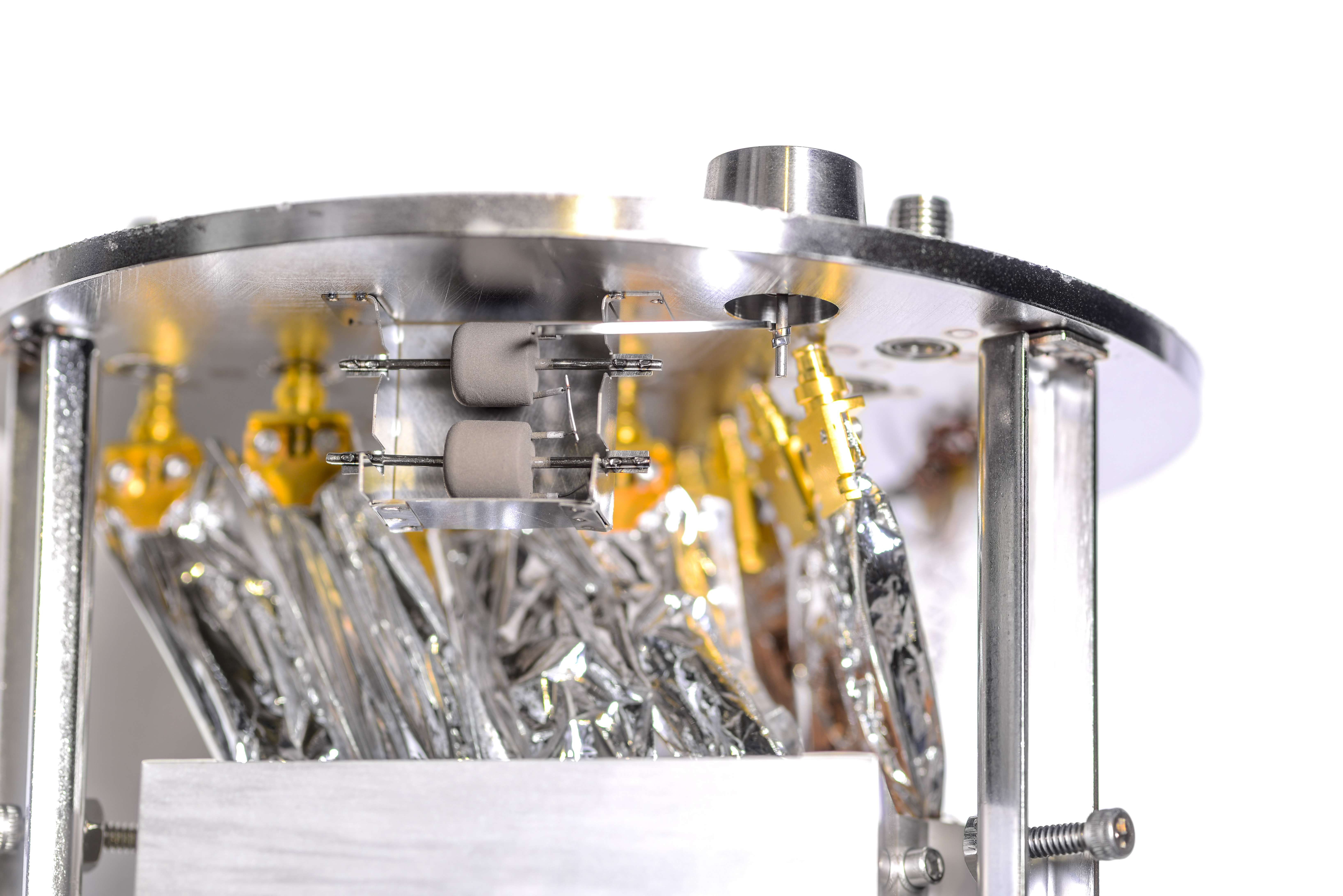
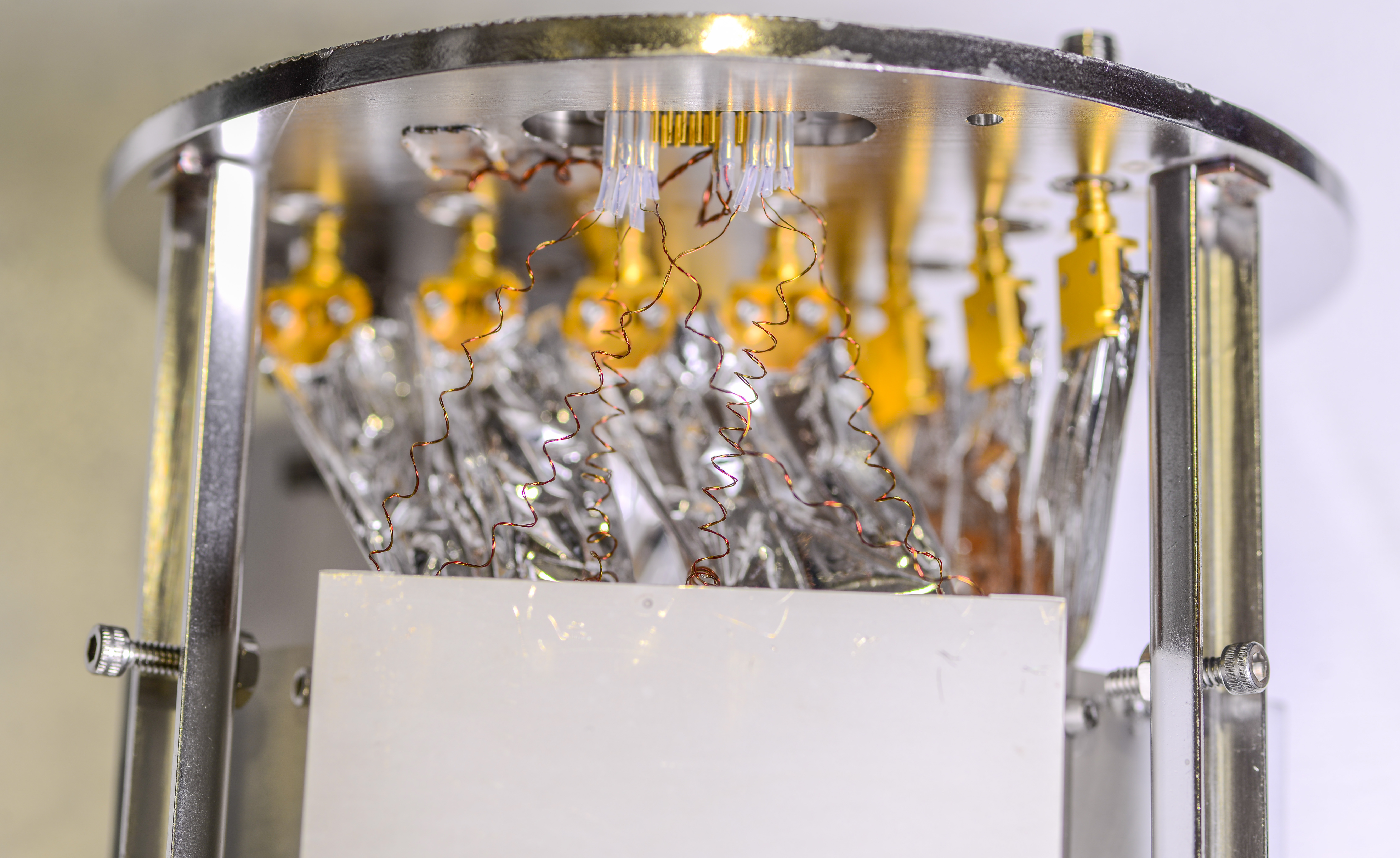
I am not 100% sure what are those cylinder things, but given the connection to separate large “connector-ish” port on external wall this must a NEG. You often see similar getter devices in traditional thermionic tubes, designed to adsorb and reduce remaining gases and vapors after Dewar is evacuated to vacuum and sealed.
Non-evaporable getters are designed with solid state active alloy. This type of getters is usually consist of zirconium alloys. NEG can be shaped as film coating but they are most often found as granules or pellets. NEG help to obtain and maintain better vacuum conditions by soaking up or bonding to trace gas molecules. There is nice video explaining details how they work from GammaVacuum

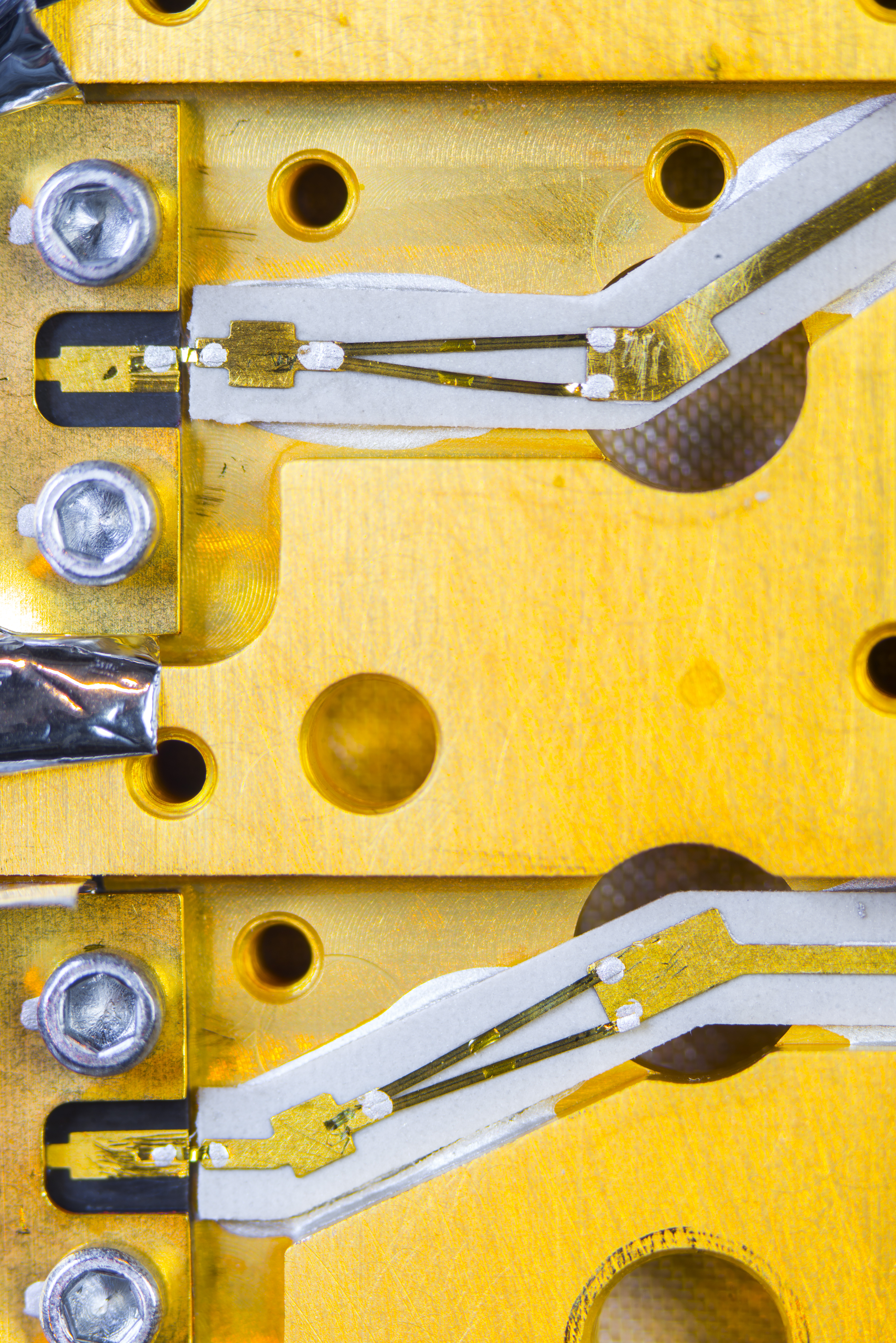
Note very thin wiring. This is done on purpose, to reduce heat leakage into cooled assembly from copper wiring. These wires are also thermally anchored with glue to inner shield on top of one filter/LNA blocks. Curly shape is also designed in with same goal – to increase length of the wire and further reduce thermal leakages.
I don’t know what is the purpose of two thicker wires and welded junction to the outer steel casing. Perhaps just grounding? Now its time to remove thin metal covers and peek onto filter structures and LNA electronics inside.
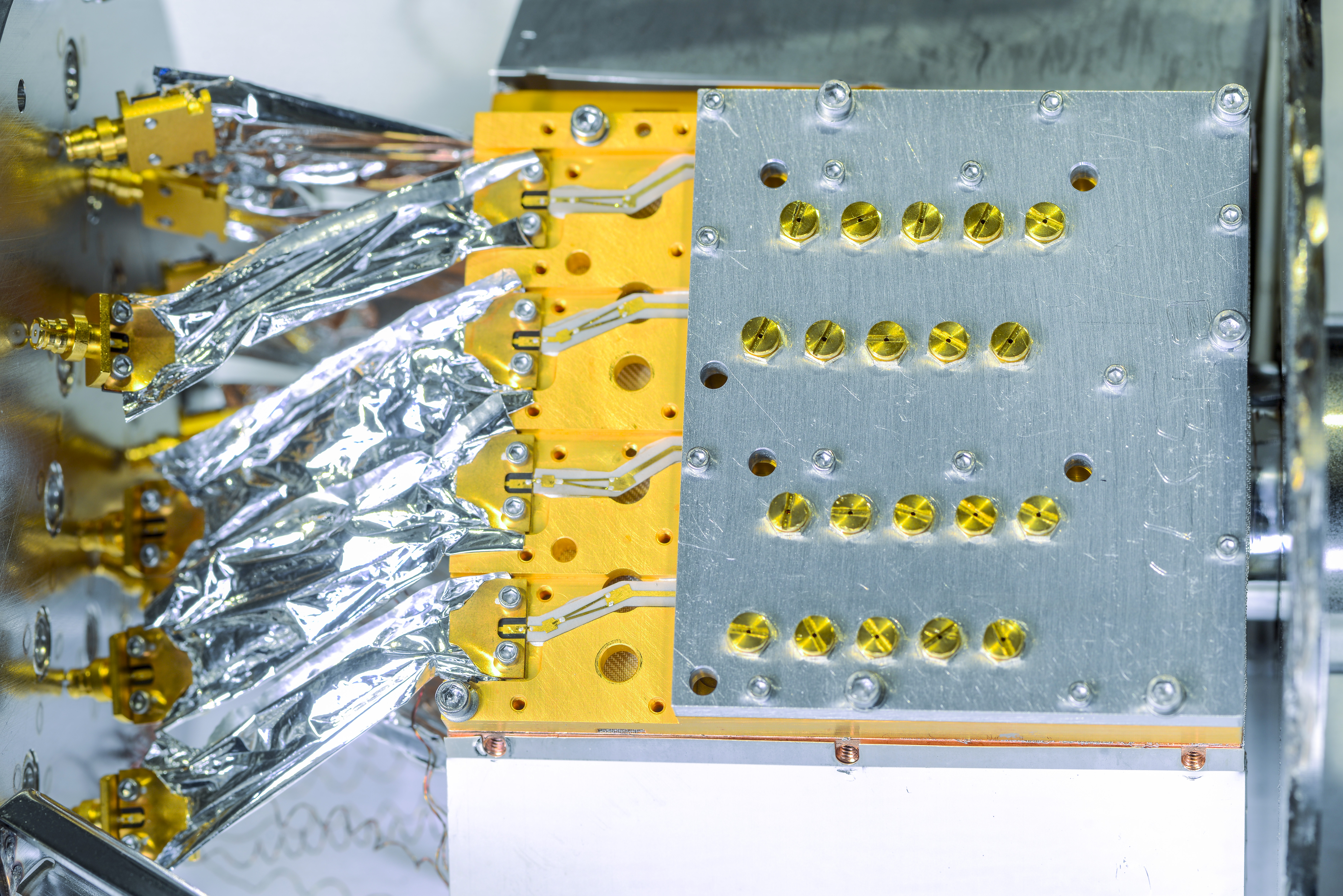
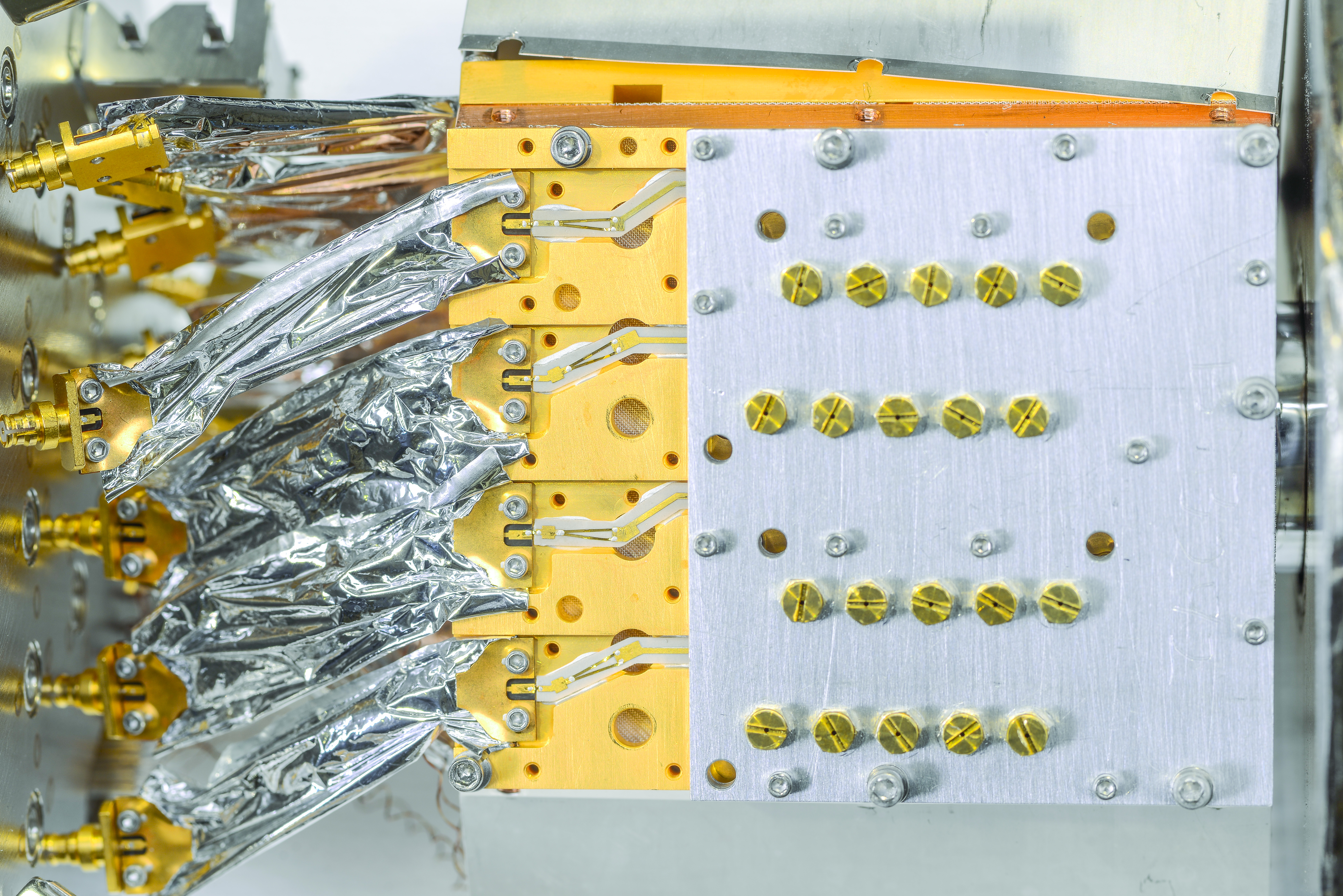
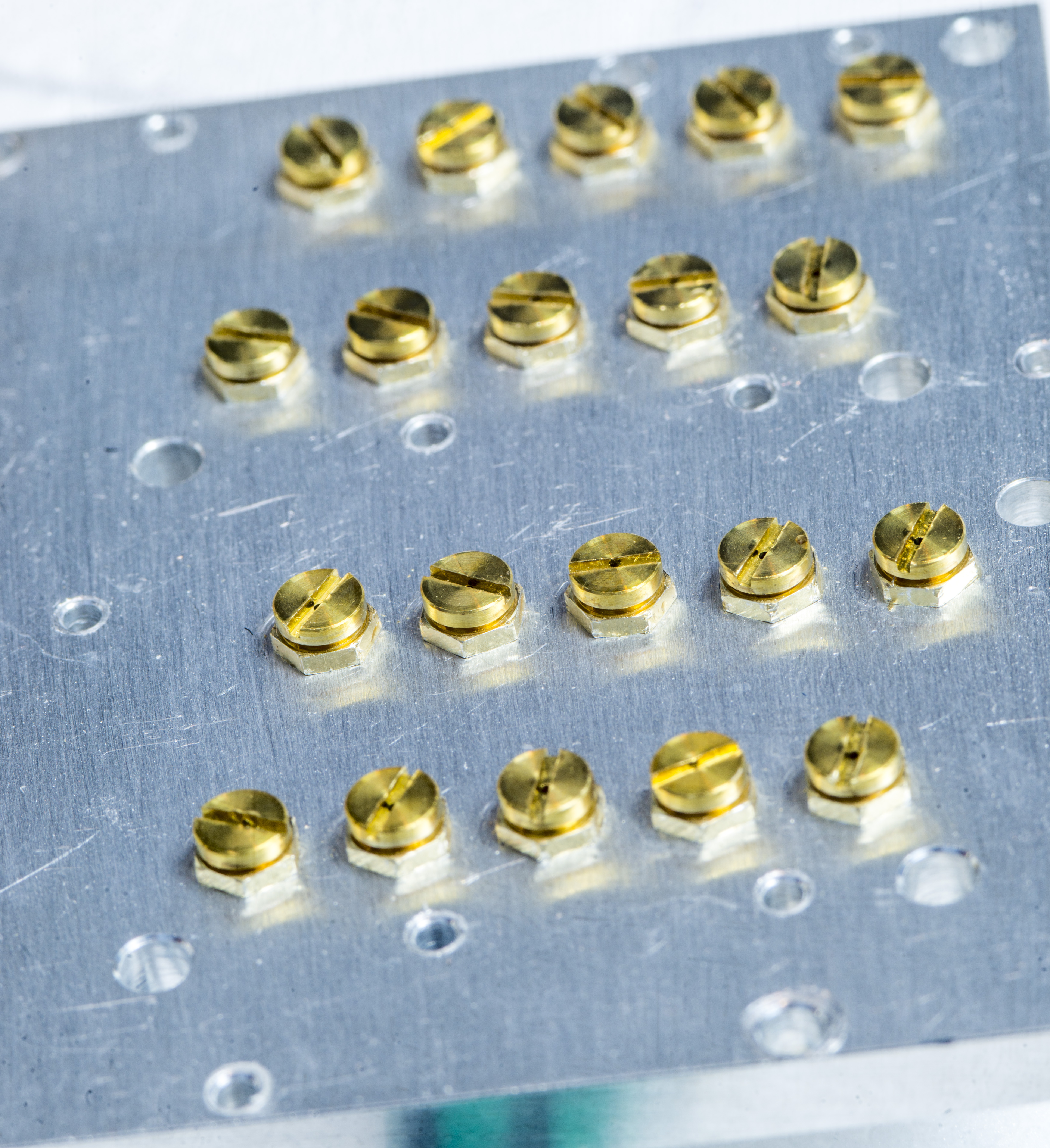
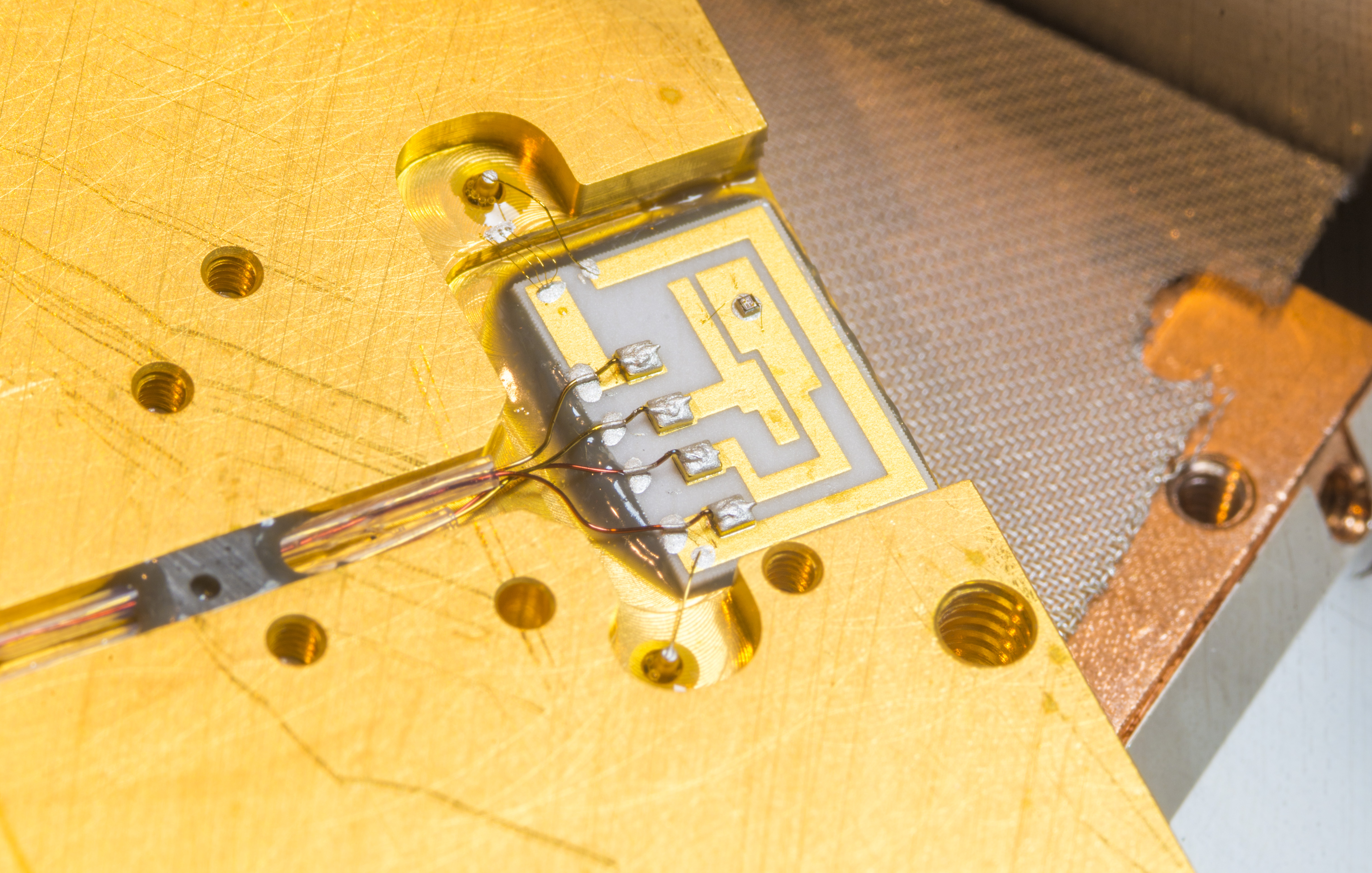
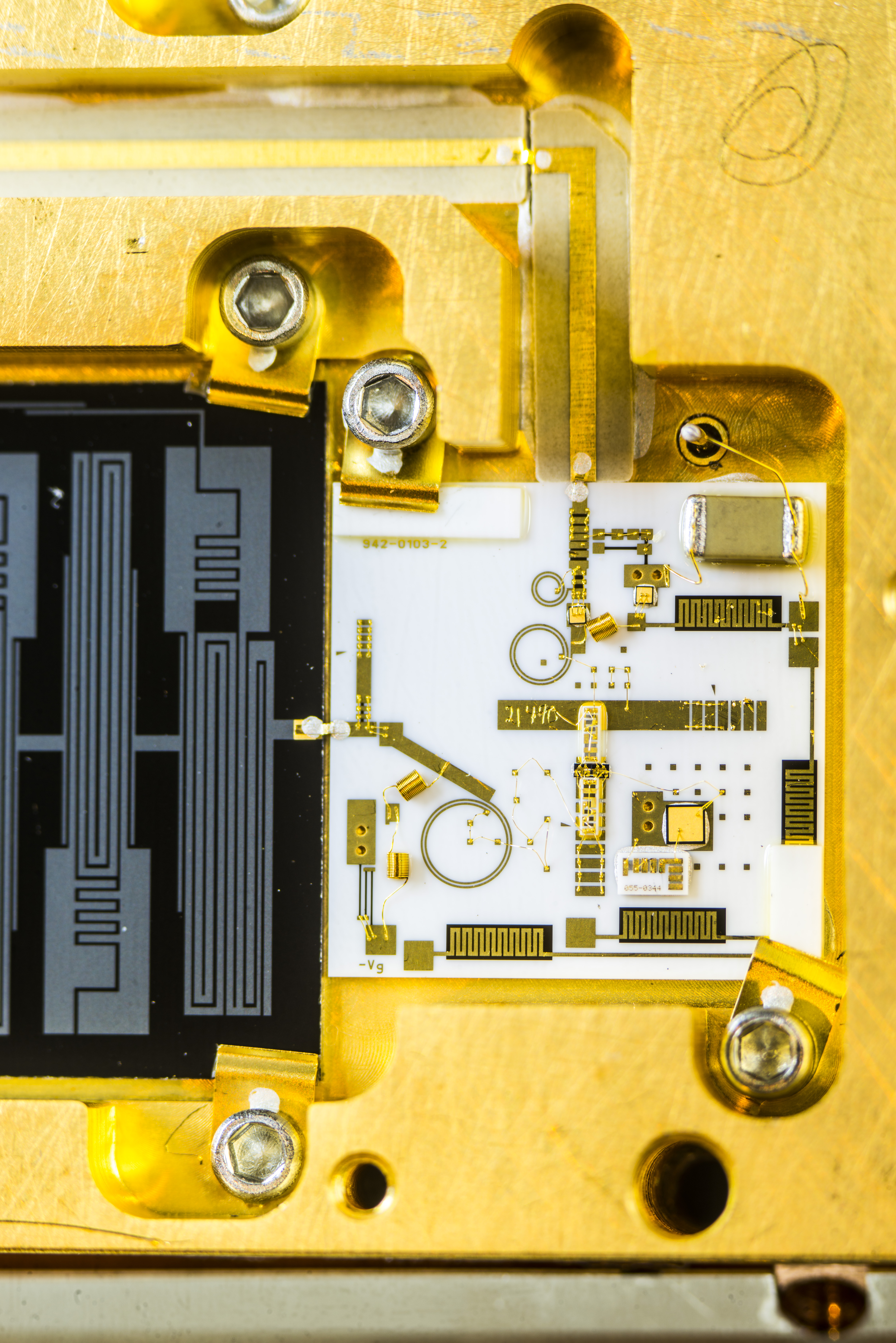
Filter frequency response is tuned during manufacturing by turning crystal rods in or out in particular spots. Mechanical change of the distance to superconducting substrate will change capacitance and affect RF signal going thru the band-pass filter in result. This way manufacturer could fine-tune each filter assembly for optimal response before sealing the whole assembly.

Each assembly has pair of LNA + high temperature superconductive planar RF filter, in own gold-plated housing. Each housing mounted to massive copper core with silver fine mesh metal sheet.
Bottom side also have little ceramic substrate with single device die. This must be a thermal sensor diode. There is one on each of the filter assembly.
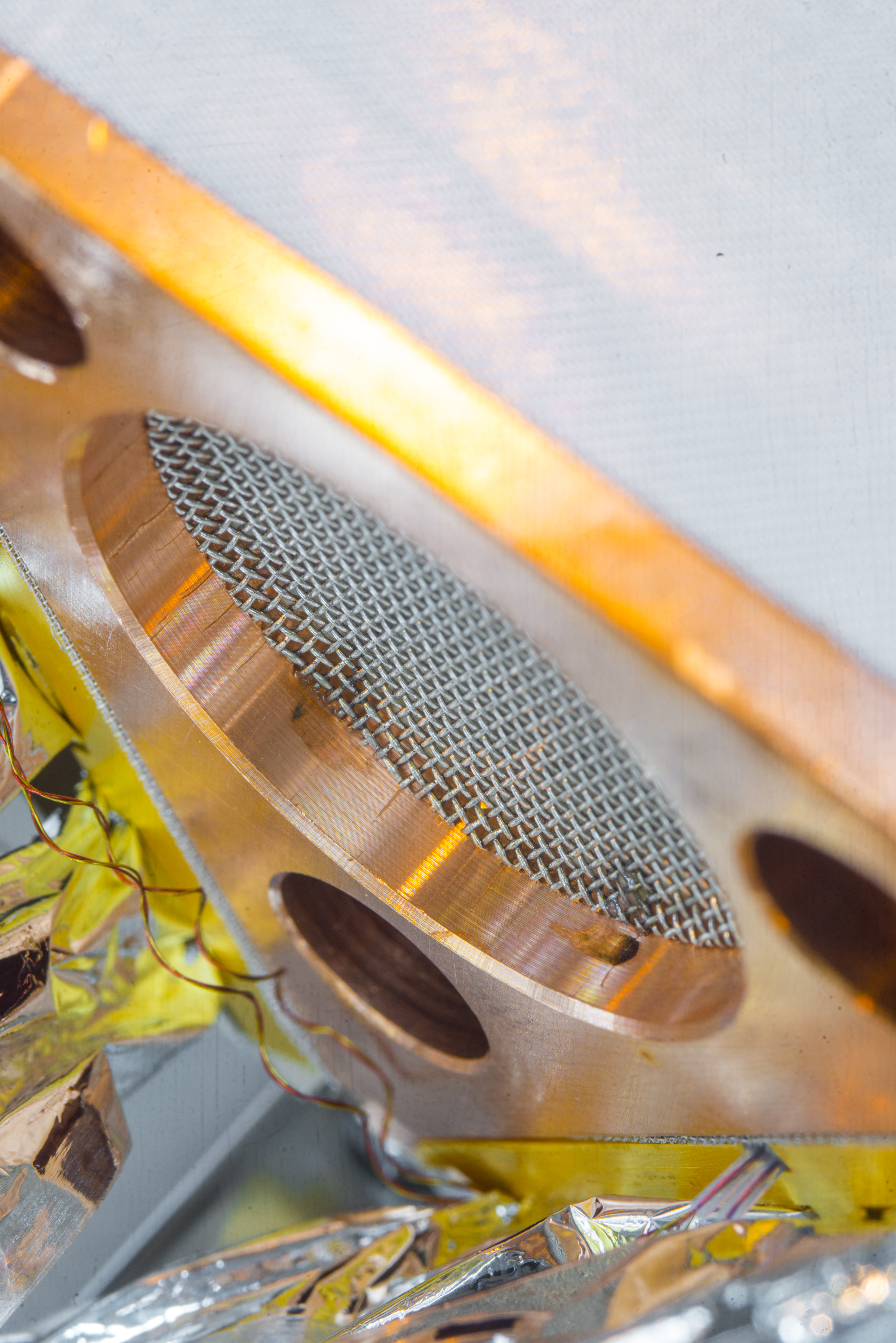
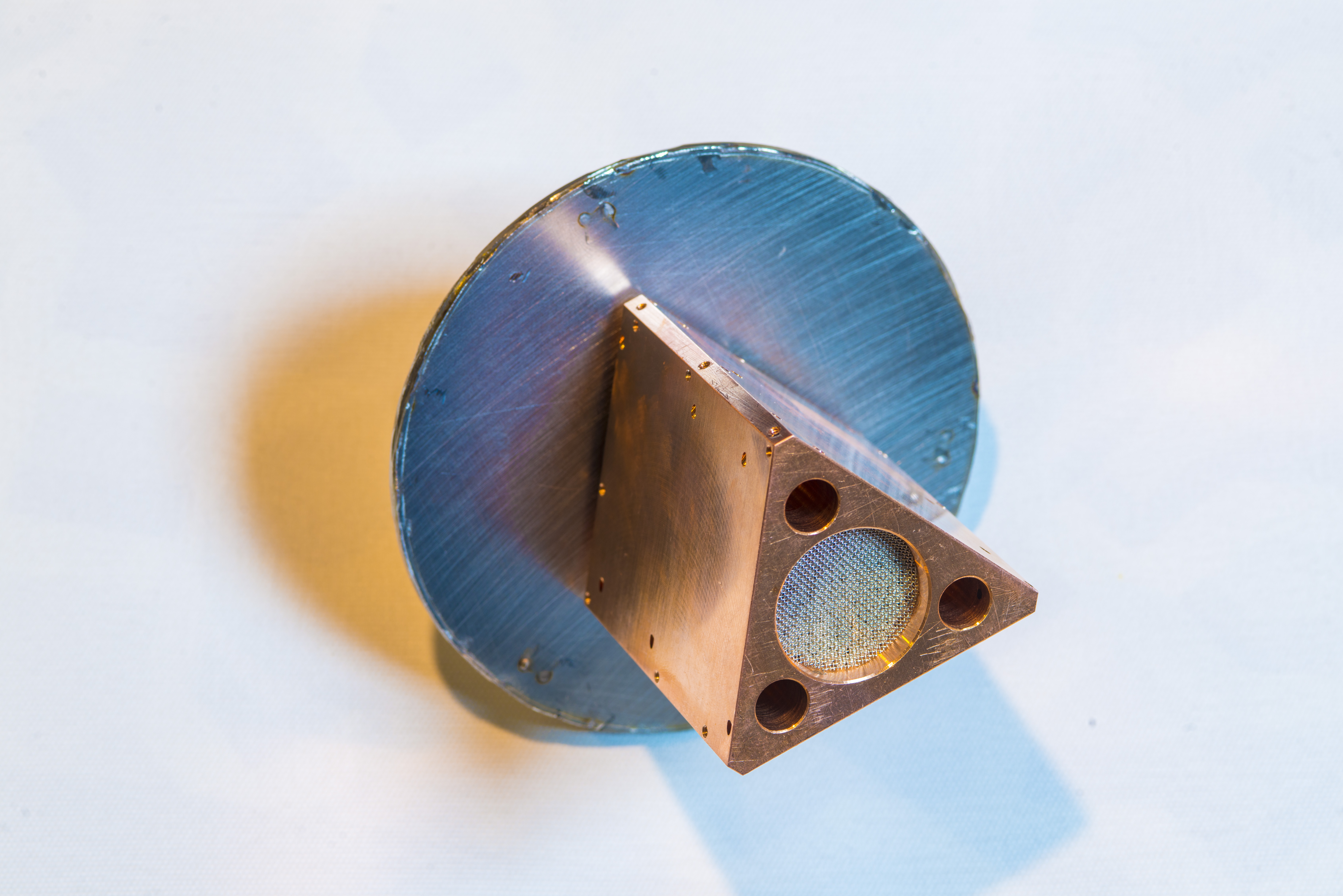
It also clear that inner dewar flanged port is thin-walled to reduce thermal coupling between cold block and outer world. Due to excessive forces applied on dewar vessel disassemly inner cylinder is damaged now.
Based on measurements from this dewar one can make CAD model of how it is built:
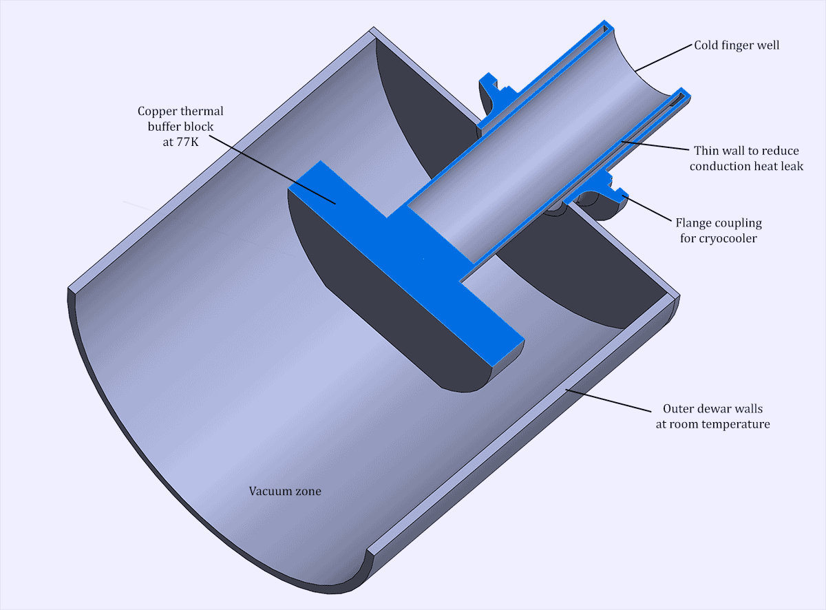
This will give nice start point for our DIY dewar project.
That’s it. Was quite interesting teardown with electronic device that look more like space-graded satellite rather than usual PCB and chip stuff.
Conclusion
We will be using this cooler to experiment with various semiconductor sensors and devices , such as precision DC references, operational amplifiers, ADC and DACs. Parameters and performance of commercial devices is almost never specified at such low temperatures, so we might discover some interesting effects, not well known to engineers outside of aerospace/physics science labs. One particular interest for me – voltage and current noise performance of high resolution ΔΣ ADC and buried zener references, such as Linear LTZ1000A or LM399.
Discussion about this article and related stuff is welcome in comment section or at our own IRC chat server: irc.xdevs.com (standard port 6667, channel: #xDevs.com). Web-interface for access mirrored on this page.
Projects like this are born from passion and a desire to share how things work. Education is the foundation of a healthy society - especially important in today's volatile world. xDevs began as a personal project notepad in Kherson, Ukraine back in 2008 and has grown with support of passionate readers just like you. There are no (and never will be) any ads, sponsors or shareholders behind xDevs.com, just a commitment to inspire and help learning. If you are in a position to help others like us, please consider supporting xDevs.com’s home-country Ukraine in its defense of freedom to speak, freedom to live in peace and freedom to choose their way. You can use official site to support Ukraine – United24 or Help99. Every cent counts.
Modified: Feb. 14, 2021, 11:34 p.m.