Intro
Generic DMM today is a very common tool to measure voltages. But that’s not only an option for some cases, when it’s more useful to have compact panel meter with multiple channels for logging and monitoring hardware, especially during extended periods of time. There are many panel meter solutions on market already, but some provide only single readout display, while multi-display ones are usually much more expensive.
So we thought about this issues a bit, and decided to resolve that in some kind of special meter, targeted just for sole purpose of providing dual voltage readout and work as fixed voltmeter. Such device would have only one voltage range, no integrated current or resistance measurement capability, so cost would be very low. Also such a design would be easier to repeat and assembly.
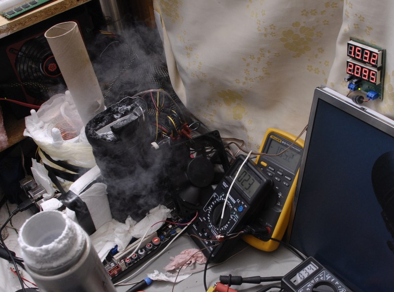
Overclockers and PC enthusiasts often push videocards and motherboards to their very limits, and usually time is short to take action, when running advanced cooling setups, specially at LN2. Having to mess with single DMMs to read different voltages, switching probes during session is generally not good idea. And that could be a disaster if you have something like 4-way SLI rig up and running, where you have at least eight voltages to monitor (four for each GPUs voltage and four for each memory voltage).
VARM – Versatile Analog Readout monitor
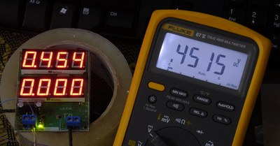
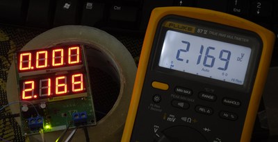
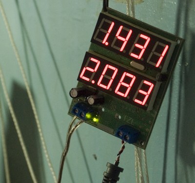
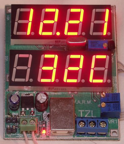
Welcome, two channel compact meter design, with bright 4-digit LED screens for voltage readouts, which are easy to read during day and night, at any angle.
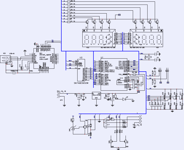
Meter have AVR 8-bit microcontroller, ATMEL ATmega8 and using of internal 10-bit SAR ADC to convert voltage input to digital code. Optional USB-UART bridge IC, CP2103 from Silicon labs is used for easy interfacting with computer via virtual COM-port. This allows using device as logging system, too, to even see how voltage was changing during bench.
With some firmware works it’s possible to have this device metering current, resistance and temperature, if you provide conversion formulas and normalize signal on inputs accordingly.
Meter taking it’s power from one common 3-pin FAN connector, usually found on motherboards and take only ~40 mADC from +12V supply.
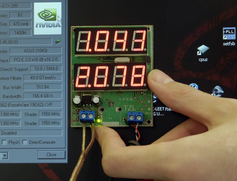
Here’s some extra photos:
Also, there is passive protection on each input, so if you done something wrong – it’s likely to survive and be protected to some extent. There is no isolation between measurement inputs and rest of device, so DO NOT try to measure mains or high-voltage circuits with it!
Mainly targeted for digital voltage levels, present on PC hardware, voltage level range is up to 3.000 VDC, to keep optimal accuracy. Range can be extended by using input voltage divider and minor modify of firmware code to add simple math function.
BOM list of project
| Qty | Component | ||
| 1 | ON 7805CG | DA1 | LDO |
| 1 | ATMEGA8L-8MI | U1 | MCU |
| 8 | BC817 SOT-23-3 | VT1-VT8 | NPN BJT |
| 2 | LED BQ-M51DRD Quad digit | HL1-HL2 | LED displays |
| 17 | SMD capacitor 0805 100nF | ||
| 1 | Electrolytic capacitor 47uF 6.3V | ||
| 1 | Electrolytic capacitor 10uF 16V | ||
| 2 | SMD capacitor 0805 18pF | ||
| 1 | IC SiLabs CP2103GM MLF28 | ||
| 8 | SMD Diode 1206 BAS32 | VD4-VD11 | |
| 2 | PLS-2 pin header 2.54mm | ||
| 1 | 0805 LED SMD red | ||
| 1 | IC LM335Z, TO-92-3 thermosensor | ||
| 9 | SMD resistor 0603 1 kΩ | ||
| 1 | SMD resistor 0603 5.1 kΩ | ||
| 2 | SMD resistor 0603 7.5 kΩ | ||
| 4 | SMD resistor 0603 10 kΩ | ||
| 1 | SMD resistor 0603 30 kΩ | ||
| 2 | SMD resistor 0603 100 kΩ | ||
| 1 | SMD resistor 0603 470 Ω | ||
| 1 | Variable resistor multiturn 3296W 10 kΩ | ||
| 1 | Variable resistor multiturn 3296W 500 Ω | ||
| 1 | Logic IC SN74HC595DW | U2 | |
| 1 | Screw connector 2 pin 5mm spacing | ||
| 1 | Screw connector 3 pin 5mm spacing | ||
| 1 | USB Type-B angled connector for PCB | ||
| 1 | 8MHz crystal oscillator |
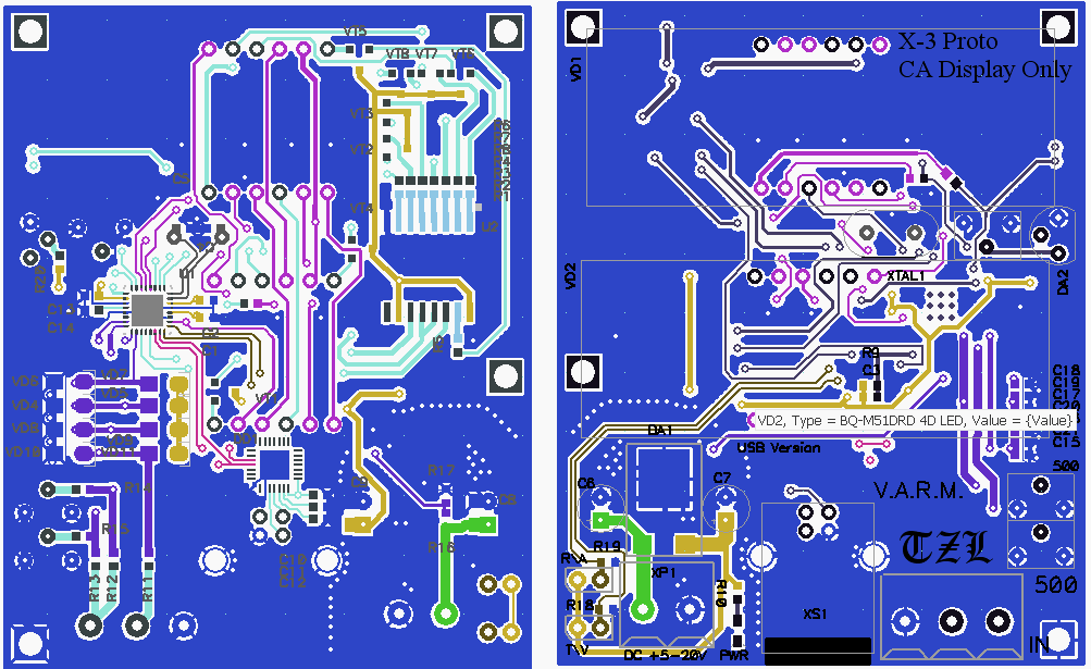
Project is open-source and available to download from here
Schematics:
There are small description wiki, timeline of changes, roadmap for future development in case such happening.
All sources and schematic (via Repository section) is uploaded as well.
Anyone can leave ticket and task after free simple registration.
Future plans
Currently I do not plan making any of these meters, and don’t have any stock of initial hardware. So if you want one – it’s up to you to get files, order PCBs on your favourite PCB factory and assemble device.
I can help with firmware to best effort case, but that’s it.
This article reposted from archive for further reference.
Modified: July 24, 2015, 1:09 p.m.