When it comes to ultra low noise, low temperature coefficient and long term stable voltage references at some point there is the question “How to power it?”. Triggered by a discussion on EEVBlog and a video by Marco Reps provided in [2] it’s time to address this very important topic in more detail.
One way to power a reference circuit is indeed the use of batteries. The advantages are, they are low noise and free of mains hum. Nowadays, many different types of batteries are available, only to mention a few of them: alkaline lead acid, NiMH, LiPo, LiFePo. Different battery types have been measured in the past and it was shown that NiCd batteries have the lowest noise [3] , [4]. Since they suffer from use of toxic cadmium, the replacement technology to go with was suggested to be NiMH.
However, operating a voltage reference or voltage standard with batteries at some point they have to be replaced or recharged, which means the reference has to be turned off. One way to come across that is described in [5] and [6] . Here, the power supplies are switched off during a ADC conversions and during that time the circuits draw quiet power from charged capacitors. As this works for an ADC this is improper for a voltage reference though.
Another possibility is to use two banks of rechargeable batteries, running the circuit on one battery pack, while the other is being charged, switching between both packs. The switching between the packs could either be based on a fixed time interval or based on the battery state of the loaded battery, which adds a further load to the battery. If both battery states, the one loaded and the one being charged, shall be observed, additional effort is needed to implement an isolated battery monitor. As charming as this solution might sound in first place, it requires twice the batteries needed to operate the reference, which comes at the cost of weight and restrictions when shipping the reference for inter-comparisons with national and more critical international courier.
So there is a need for powering a reference by mains power, while the power supply should behave battery-like and thus low noise, but also low leakage, with no coupling to earth. In addition it should be light in weight. As challenging as it sounds, it’s hard to achieve but possible.
But how do you know if a mains line power supply behaves like a battery for the voltage reference? Connect it to a battery and monitor its output voltage, then switch it to your mains line power supply. If it stays low noise and doesn’t shift in output voltage, then you reached the goal.
What are the solutions available on the market and what is used in commercial voltage references?
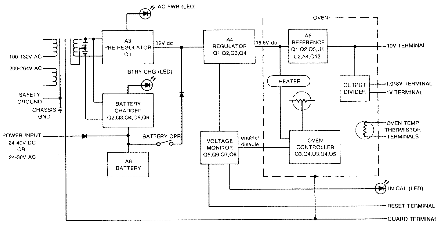
Figure 1 : Block diagram of Fluke 732A
There are solutions mentioned using guarded line frequency transformers which are bulky and often have a high unguarded capacitance or specially constructed toroidal double-screened transformers [7] . Such line transformers are used e.g. in Fluke 732A and available also as toroidal (see Figure 1) or as R-core transformers with screen (see Figure 2).
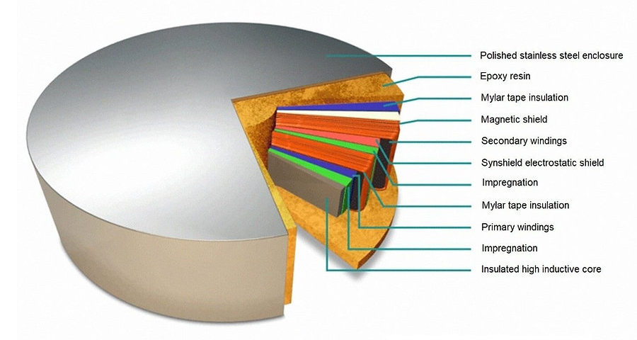
Figure 2 : Shielded toroidal transformer [8] .
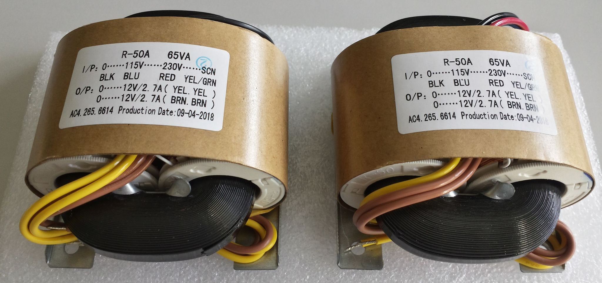
Figure 3 : R-core transformer
Such R-core transformers were tested for low noise lab power supplies combined with LT3045, but are large, heavy and don’t reach the performance of solutions discussed next [9].
Modern solutions use low noise DC-DC converters as presented in [10] [11] [12] [13] and [14] . Although low noise can be achieved high isolation requires additional effort with respect to the transformer. In [15] a coaxial cable transformer is described. It is based on coaxial cables wound to a core for reducing primary to secondary winding capacitive coupling, which results from the mutual capacitance therebetween. Included between and concentric with inner and outer coaxial conductors, operating as primary and secondary windings, is a selectively grounded shield conductor. This shield conductor is grounded such that there is no instantaneous potential difference between corresponding points on the shield and secondary winding.
In [16] an isolated transformer for use in isolated DC-to-DC switching power supplies is presented, that has been used in DMM7510. The isolated DC-to-DC switching power supply includes an isolation transformer with a magnetic core, a first winding around the magnetic core, a first winding-shield around the magnetic core, a second winding-shield within the first winding-shield, and a second winding within the second winding-shield. There is no direct coupling between the first winding and the second winding since the second winding is enclosed within the second winding-shield and the second winding-shield is enclosed within the first winding-shield.
Pickering transformer
In [17] images and schematics of the Wavetek 7000 reference including the DC-DC transformer are made available. The transformer used there is described in [18] . The construction is based on two ring cores, one for the primary and one for the secondary side with copper windings. The cores are enclosed by electrostatic screens, made of slightly conductive 0.1 to 500 Ω/square material, acting as a Faraday cage. “…The two enclosed wound cores are magnetically coupled with a number of turns of wire connected as a closed loop. This coupling winding then encloses both cores forcing the magnetic field in one core to be equal (and opposite) to the other.
The coupling winding therefore has no net voltage included in it…”. Such a transformer is used in Wavetek 7000 and early units of Fluke 7000, manufactured by Siga UK under the part number BT4974 in W7000 and CT4974 in F7000, is driven by a discrete circuit, but other than that there is little to nothing known about it. So it’s fortune to have at least some images and measurements on a real version of it. In the following images the primary side is on the left, while the secondary side is on the right. Figure 4 shows the transformer removed from the board.
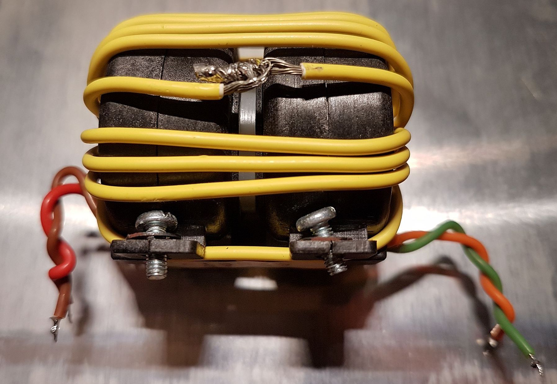
Figure 4: Wavetek & earliy Fluke 7000 transformer of DC-DC converter
The coupling between primary and secondary side contains 15 windings, which with respect to [19] is made by PTFE and gives a magnetically coupling of 99.7 %.
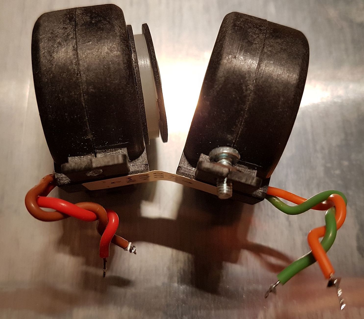
Figure 5: Wavetek & earliy /Fluke 7000 transformer of DC-DC converter – coupling winding removed
Once stripped from the coupling windings the transformer comes apart. Figure 5 shows the transformer with the coupling wire removed. There are additional two conductive washers and some white insulator between them, by the looks of it made of POM. In Figure 6 and Figure 7 the screens have been opened.
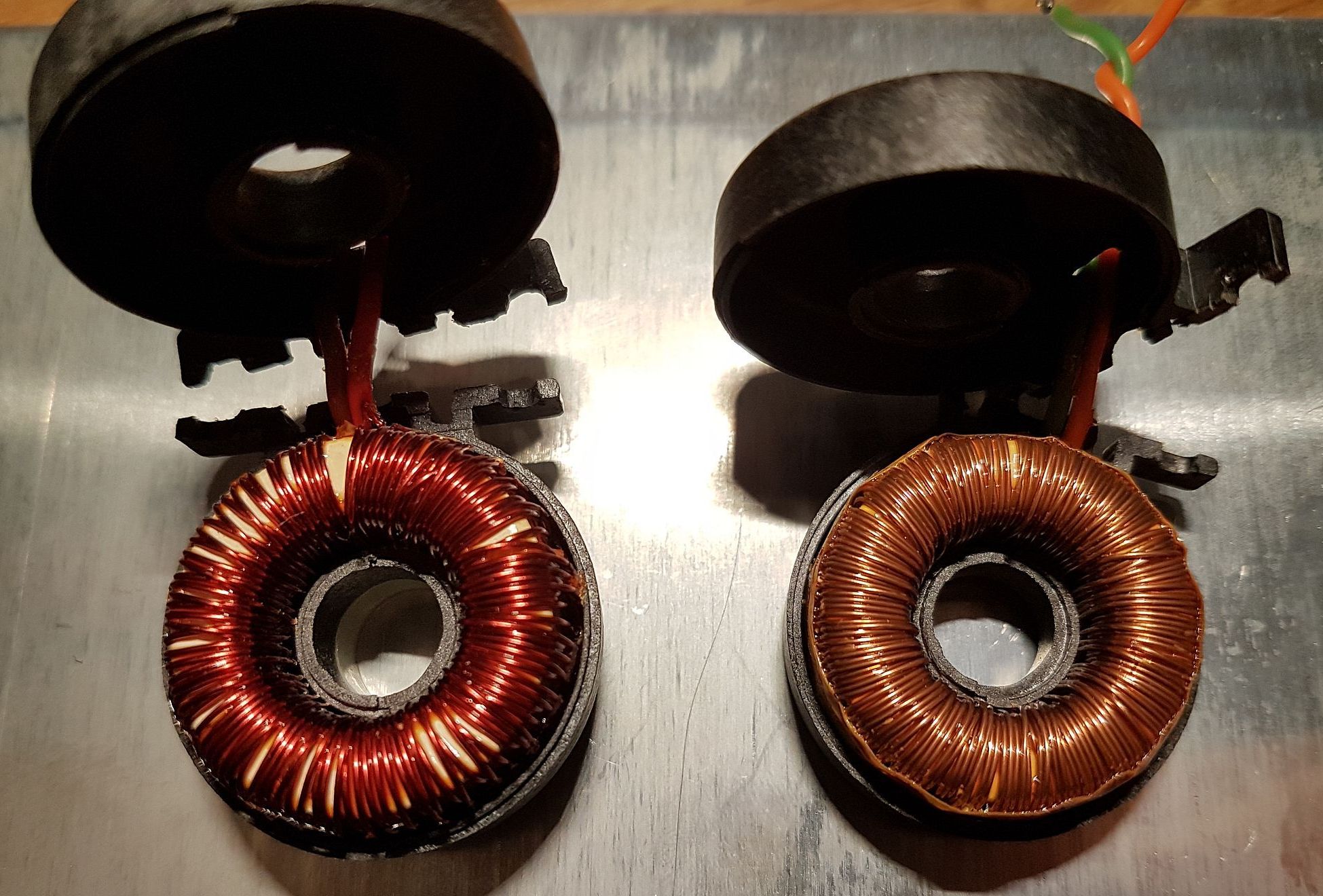
Figure 6: Wavetek & earliy Fluke 7000 transformer of DC-DC converter – primary side (left), secondary side (right)
There are less windings with thicker wires used for the primary side.
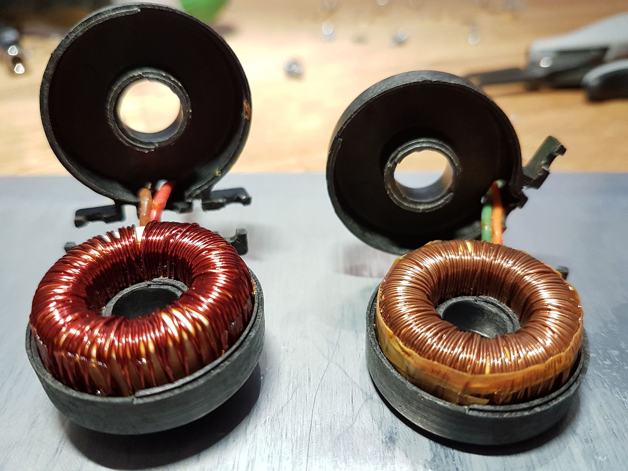
Figure 7: Wavetek & earliy Fluke 7000 transformer of DC-DC converter – primary side (left), secondary side (right)
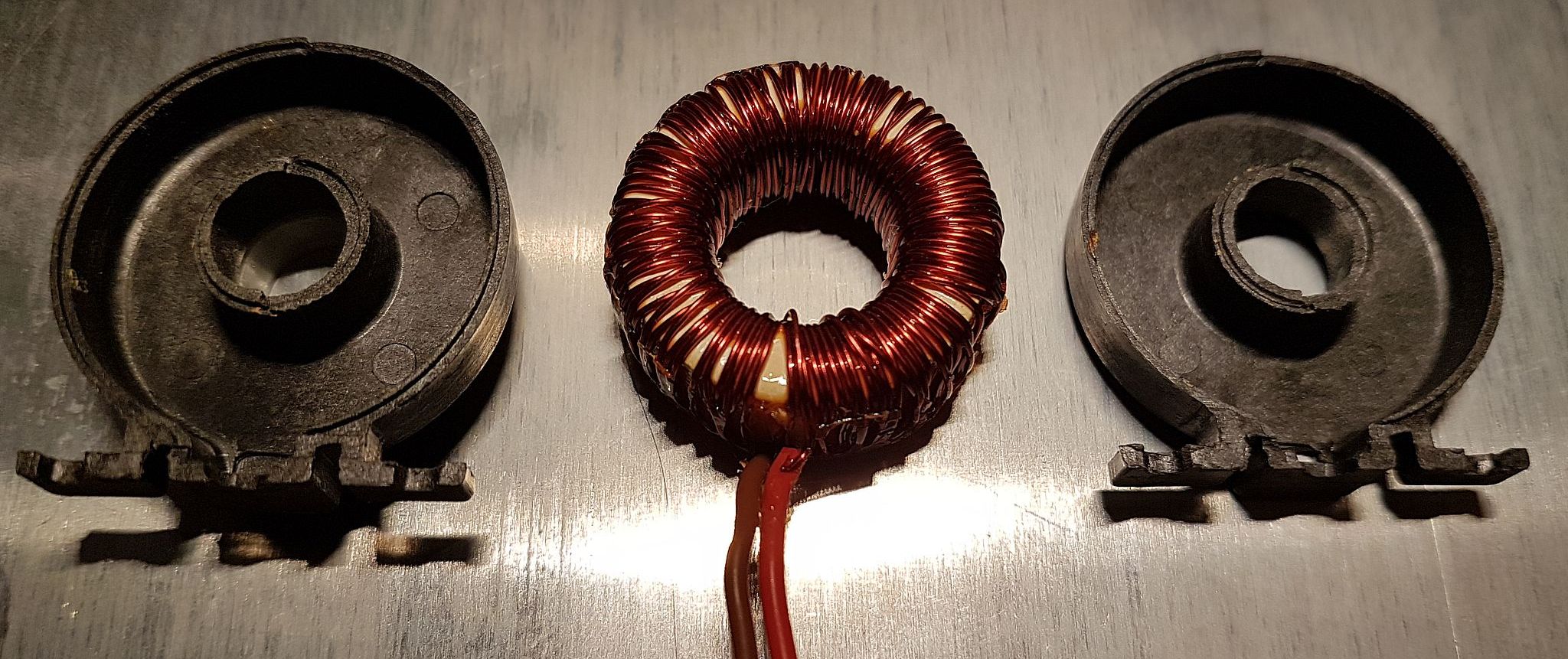
Figure 8: Wavetek & earliy Fluke 7000 transformer of DC-DC converter – primary coil and screen components
The screens are made by two equal parts (see Figure 8 and Figure 9).
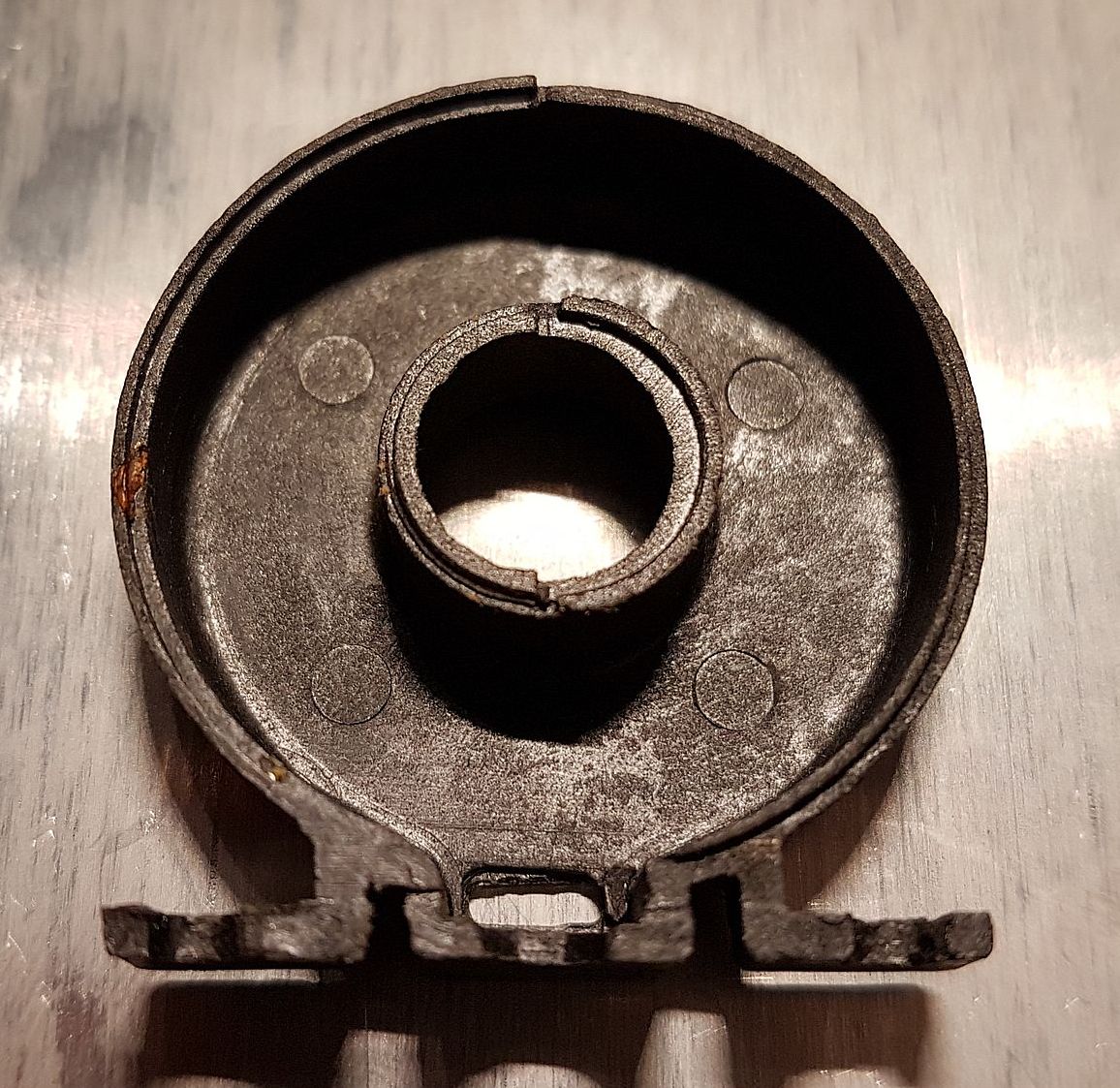
Figure 9: Wavetek & earliy Fluke 7000 transformer of DC-DC converter – single screen component
What is known from measurements is, that the discrete oscillator is operating at 4.323kHz … 4.365kHz. The copper wire of the primary side has a diameter of Ø = 0.3 mm, an inductance of L ≈ 46.175 mH and a Q ≈ 12.498 measured at 10 kHz. The secondary side has a wire diameter of Ø = 0.25 mm, an inductance of L ≈ 111.06 mH and a Q ≈ 12.382 measured at 10 kHz. With this numbers given, a Spice simulation was set up that shows a frequency of 4.179 kHz, so pretty close to what was measured (see Figure 10).
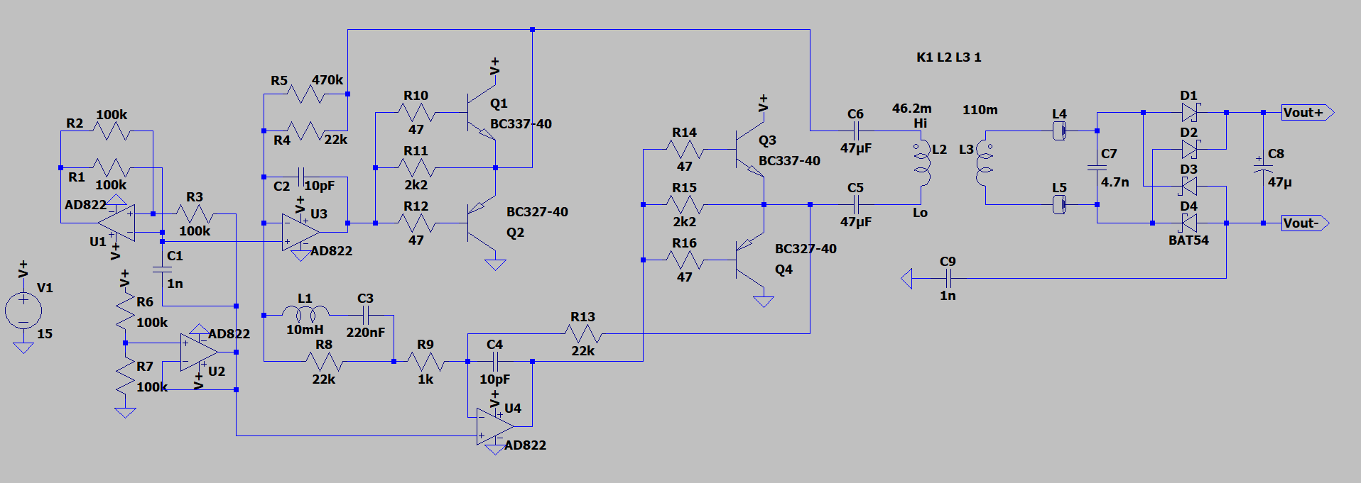
Figure 10: Schematic of the discrete build DC-DC converter in Wavetek & earliy Fluke 7000
Furthermore, the number of turns, the measured inductance and the dimensions with an outer diameter of 25 mm, an inner diameter of 16 mm and a height of 10 mm allow to calculate the core material with an AL = 16000 (16 µH per turn). Which fits best is a T60004-L2025-W375 ring core manufactured by Vacuumschmelze.
In later models of the Fluke 7000 the transformer was reworked and driven by a push-pull stage with Analog Devices LT1533 (see Figure 11). The transformer now contains center taps on both sides. The inductance of each primary winding is L ≈ 4.2 mH and L ≈ 13.0 mH on the secondary side, while the copper wire diameter on the primary measures Ø = 0.55 mm and Ø = 0.34 mm on the secondary. This version of a transformer called ISOP is mentioned in [19] and [20] . Here, the conductive screen is described to be made out of an injection molded, carbon fiber loaded plastic with a resistivity of 5 Ω/square. The oscillator frequency was measured to be ~7.95 kHz.
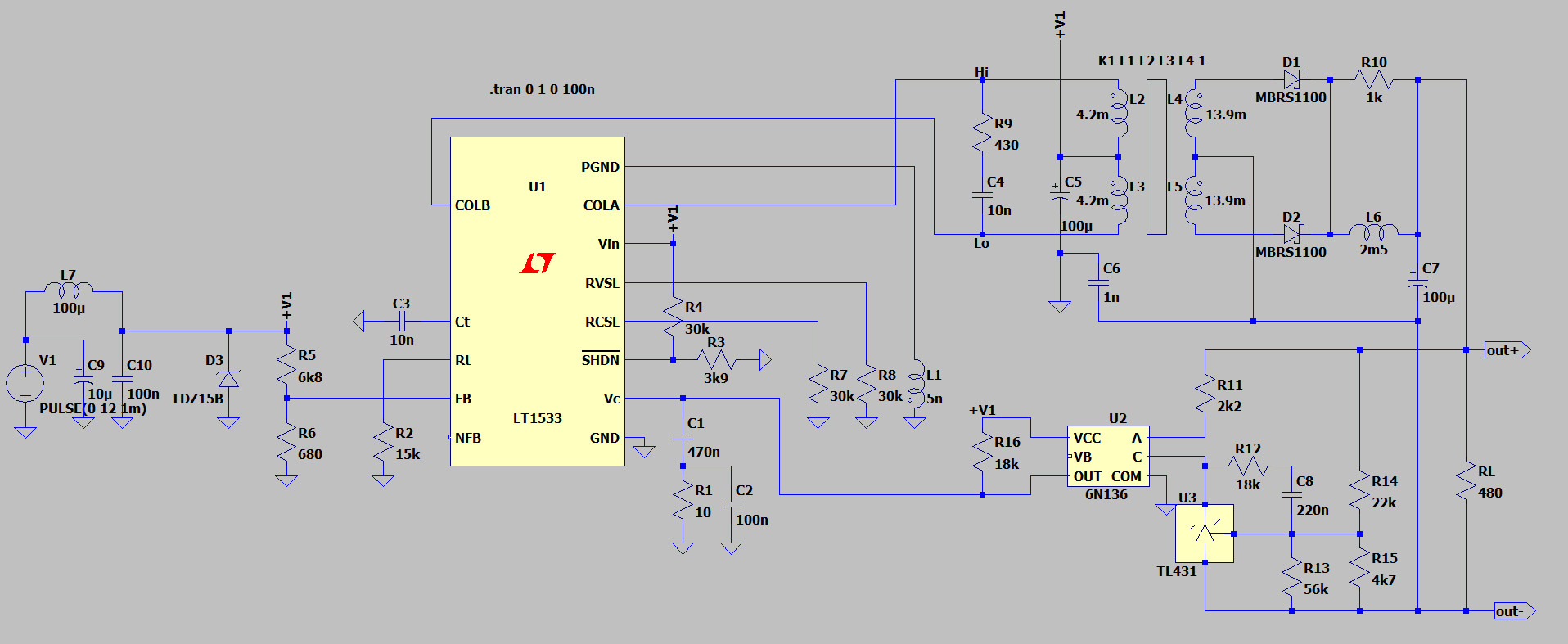
Figure 11: Schematic of DC-DC converter based on LT1533 in Fluke 7000
The advantage of using the LT1533 rely by drive and load waveforms implementation as slew controlled to prevent very fast edges. This makes drive signals as symmetrical as possible so that within the primary screen, for example, positive and negative going edges are fully balanced. Together with the use of high permeability, high saturation density, “nano crystalline”-cores…” a relatively low-frequency operation (~7 kHz) is possible, which enables reasonably high power density compared with 50/60 Hz and further allows more aggressive slew rate limiting. It was shown that with this new transformer version and drive circuit leakage currents of 200 pA peak-to-peak were reached. Impressive numbers!
In practice the overall superior performance is reached by powering either the Wavetek or the Fluke 7000 by a linear wall power supply together with the somewhat special DC-DC converter.
While the primary screen is directly tied to primary ground and earth, the secondary screen is connected to secondary ground which itself is connected to earth via a 1 nF high voltage rating capacitor.
This screen connection is important for correct measuring the primary to secondary capacitance. The screens must not kept floating for correct measurement.
Projects like this are born from passion and a desire to share how things work. Education is the foundation of a healthy society - especially important in today's volatile world. xDevs began as a personal project notepad in Kherson, Ukraine back in 2008 and has grown with support of passionate readers just like you. There are no (and never will be) any ads, sponsors or shareholders behind xDevs.com, just a commitment to inspire and help learning. If you are in a position to help others like us, please consider supporting xDevs.com’s home-country Ukraine in its defense of freedom to speak, freedom to live in peace and freedom to choose their way. You can use official site to support Ukraine – United24 or Help99. Every cent counts.
Modified: May 26, 2022, 3:15 a.m.
References
- EEVBlog : Power supply for voltage references
- Marco Reps video : eXtReMe iSoLaTiOn (Low Leakage Power in Precision Electronics)
- Ch. K. Boggs et al., "Measurement of voltage noise in chemical batteries"
- G. Hoffmann, "Noise Measurements On Chemical Batteries"
- Rick Walker, "Recent Advances in Resistance Thermometry Readouts", Fluke, 2010
- US8120327, System and method for using stored electrical energy to quit power sensitive measurement circuits", Fluke Corporation, 2012
- B. P. Kibble, "Guidance on eliminating interference from sensitive electrical circuits"
- MPAudio product page: Premium Audio Grade Transformer
- EEVBlog : Ultra Low Noise Lab Power Supply Extender for your existing lab supply
- Jim Williams, "Some Thoughts on DC/DC Converters", AN29, 1988
- Jim Williams, "A monolithic switching regulator with 100 µV output noise", AN70, 1997
- Jim Williams, "High Voltage, Low Noise, DC/DC Converters", AN118, 2008
- "Measurement and filtering of output noise of DC-DC converts", Interpoint Application Note
- Art of electronics – The X-chapters
- US3717808, "Shielded coaxial cable transformer", Communications Satellite Corporation, 1973
- US9478351, " Isolated transformer for use in isolated DC-to-DC switching power supply", Keithley Instruments, 2016
- EEVBlog : Wavetek 7000 forum thread
- EP0864165, "High isolation power transformer", Metron Designs, 1997
- J.M. Williams et al., "Design and metrological applications of a low noise, high electrical isolation measurement unit", 2008
- John Pickering, "A new compact isolated power supply for electrical Metrology at low signal levels"