Introduction Zeiss Axio line of microscopes
Carl Zeiss is a recognized name in imaging instrumentation world. Their microscopes are used in many industries across the globe for decades already. Microscopes been in use at xDevs lab and projects for many years, but mostly with low magnification and large working distances for reworking electronic assemblies and modern SMT circuits. But I always wanted to have dedicated high resolution microscope to explore the world of micro-fabrication and chip designs, investigate failed components and overall look into tiny things around us. I had a chance to glance into high-end Zeiss Axioskop 2 during one of the visits to TheSignalPath and was amazed with quality possible. Shahriar published few videos about his setup as well here, here and here. Famous HP3458A U180 IC was used as speciment for inspection and you can check the stacked panoramic image captured during that visit in this post. At that point I knew I’d have to get something similar at xDevs as well.
Today that dream came true and now we get own Zeiss piece of optical masterpiece in the lab. In this article we’ll study and learn about particular Zeiss microscope system called Axiotron, originally designed for integrated circuit wafer inspection. System xDevs acquired recently came with the following components:
- Zeiss 45 28 07 [02] Top frame (for Axioplan or Axiophot)
- Carl Zeiss 45 74 31 Bedienpult Axiomos
- Zeiss 45 29 30 Binocular module/tube with dovetail third port for camera
- Zeiss 45 29 95 C-mount camera port adapter
- Zeiss 45 28 03 electronic board (internal)
- Carl Zeiss 45 74 27 MCU 27 controller unit (probably from different microscope)
- Zeiss 45 36 55 fixed analyzer slider bar
- Zeiss 44 64 75 bright light lamp filter
- Zeiss 44 72 17 [01] 100W Halogen lamp unit
- Zeiss 44 23 25 objective – 5x/0.15 HD DIC Epiplan-Neofluar air infinity corrected
- Zeiss 44 23 35 objective – 10x/0.3 HD DIC Epiplan-Neofluar air infinity corrected
- Zeiss 44 23 45 objective – 20x/0.50 HD DIC Epiplan-Neofluar air infinity corrected
- Zeiss 44 23 55 objective – 50x/0.75 HD DIC Epiplan-Neofluar air infinity corrected
- Zeiss 44 23 85 objective – 100x/0.9 HD DIC Epiplan-Neofluar air infinity corrected
- Zeiss 44 26 90 objective – 150x/0.95 HD DIC Epiplan-APOCHROMAT air infinity corrected
- Zeiss Plan Neofluar 5x/0.15 DIC slider
- Zeiss Plan Neofluar 10x/0.3 DIC slider
- Zeiss 44 44 40 Plan Neofluar 20x/0.5 DIC slider
- Zeiss 44 44 54 Plan Neofluar 50x/0.75 DIC slider
- Zeiss 44 44 82 Plan Neofluar 100x/0.9 DIC slider
- Zeiss 45 31 43? Nosepiece controller/objective selection motor unit
There are many variants and customized units that Zeiss made over the years and it looks like this particular system was a part of larger setup, designed to be automated. There seem to be no way to switch mode of operation from dark-field to bright-field manually? Lots to learn still, as I never used Zeiss system like this in the past.
Manuals and materials
TBD
Disclaimer
Redistribution and use of this article, any part of it or any images or files referenced in it, in source and binary forms, with or without modification, are permitted provided that the following conditions are met:
- Re-distributions of article must retain the above copyright notice, this list of conditions, link to this page (https://xdevs.com/article/zeiss_axiotron/) and the following disclaimer.
- Re-distributions of files in binary form must reproduce the above copyright notice, this list of conditions, link to this page (https://xdevs.com/article/zeiss_axiotron/), and the following disclaimer in the documentation and/or other materials provided with the distribution, for example Readme file.
All information posted here is hosted just for education purposes and provided AS IS. In no event shall the author, xDevs.com site, Zeiss or any other 3rd party be liable for any special, direct, indirect, or consequential damages or any damages whatsoever resulting from loss of use, data or profits, whether in an action of contract, negligence or other tortuous action, arising out of or in connection with the use or performance of information published here.
If you willing to contribute or add your experience regarding instrument repairs or provide extra information, you can do so following these simple instructions.
Exterior and design
Axiotron in it’s glory. Round chuck is a vacuum holder for wafers that I have removed from the XY table.
Boxes at the table corners are covered stepper motors for positioning the stage. There is no manual knobs or controls to move table by hand.
Objectives are all free air with magnification range from 5x to 150x. All but 150x can be used with darkfield, brightfield and DIC imaging modes. 150x is brightfield only objective.
For darkfield light from fiber source is routed “around” the lens center core and focused into the object as a ring.
Higher magnification objectives have front surface retractable, perhaps to prevent crushing the sample/wafer in case of physical contact?
50x objective has two thin metal shims on it’s threaded port, perhaps for finetuned adjustment?
![]()
Each objective port on a turret has a port for DIC slide. Each slide is unique to the objective, so they should match.
Few had some discoloration on the edges, not sure if that would be problematic for image quality or not.
Microscope came with a set of matching slides except for 150x objective.
This microscope was “installed” at original customer site in November 1993. Old but still capable to produce great images, I’d hope :)
There is large D-SUB 50 contact female connector at the back. I have matching cable that also has female D-SUB 50 contact connector on the other end, but couldn’t find any information online where this cable supposed to connect, as there is no D-SUB 50 connector on MCU 27 controller module that came with microscope.
There is another circular connector at the left side of the microscope base body with 15 male pins. I have matching cable for this connector that terminates with same 15 male pin connector type.
All parts and body covers are machined very nice, as expected from recognized german engineering and instrumentation manufacturer. Solid design and build, nothing wobbles or wiggles like in the cheap learning scopes.
Cover on a hump near camera mount hides some space for top optical matte port? Don’t know what that does yet :)
Halogen brightfield lamp HAL 100:
Some laser unit on the side?
There is some box cover with laser emission warning on the right side of the microscope. I don’t know the purpose of this yet. Maybe some kind of detector/sensor as it’s laser class 1 which is the lowest power/safety rating.
There is a smaller bar with filter 44 64 75 right next to “laser” cover box.
There are two rods that can be turned (top one turns rather stiff), an aperture(?) rod that slides in and out and another unused circular 12-contact male connector. It was capped with plastic cup and internally is terminated to ribbon cable that is not connected to anything.
MCU 27 controller unit
Not sure if this is correct controller for this particular microscope since there is no matching DB connector port to connect with microscope frame. This controller has rather hefty metal enclosure with plenty of vents, but no fan inside.
On the back we get rows of D-SUB type connectors, mains IEC entry port with fuse and voltage selector. 220-240V option is crossed out on the label. Ports are labeled as following:
- DB9 female for “Mouse”
- DB9 male for “COM”, perhaps RS-232 data interface?
- DB15 blue female for “XYZ Panel”, perhaps for remote joystick controller
- DB15 white female for “1”
- DB15 white female for “2”
- DB25 female for “Y” motor drive axis control/sensing
- DB25 female for “X” motor drive axis control/sensing
- DB25 female for “Z” motor drive axis control/sensing
- DB37 female for “Axiotron S”, perhaps main connection to the microscope “Axiotron S” body? It does not match our DSUB 50 port here.

Removing six bolts reveals internal design of MCU 27:
Large linear power transformer Zeiss 457427-8030 powers whole thing. Next to it we got row of five fuse holders (each fuse tested OK). There are some relays, some digital logic, couple AD558JN chips and three blocks for motor drive/control with large opamp on individual heatsinks. There are no user controls, buttons or indicators on the front of the controller. MCU 27 clicks a relay when powered up.
Connecting it to the X and Y stage motors didn’t do anything. Hooking up joystick Zeiss 457431 also didn’t change situation, moving joystick or pressing buttons didn’t generate any activity at the microscope X/Y positioner.
Most likely this MCU 45 74 27 controller require different joystick unit, perhaps Zeiss 45 24 51 model?
Some bits inside with opening covers:
Test images with camera just laying at camera port (no adapter yet)
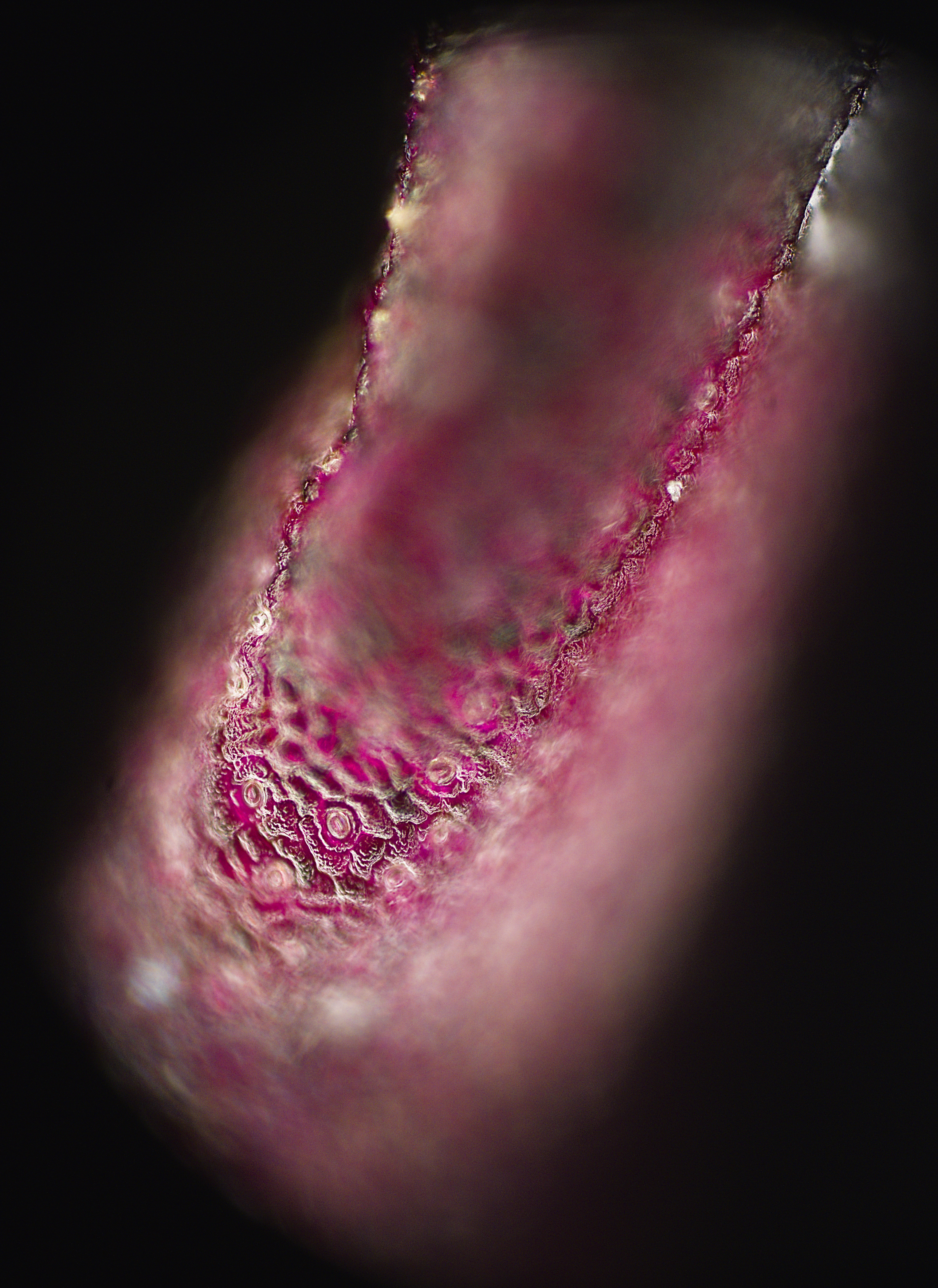
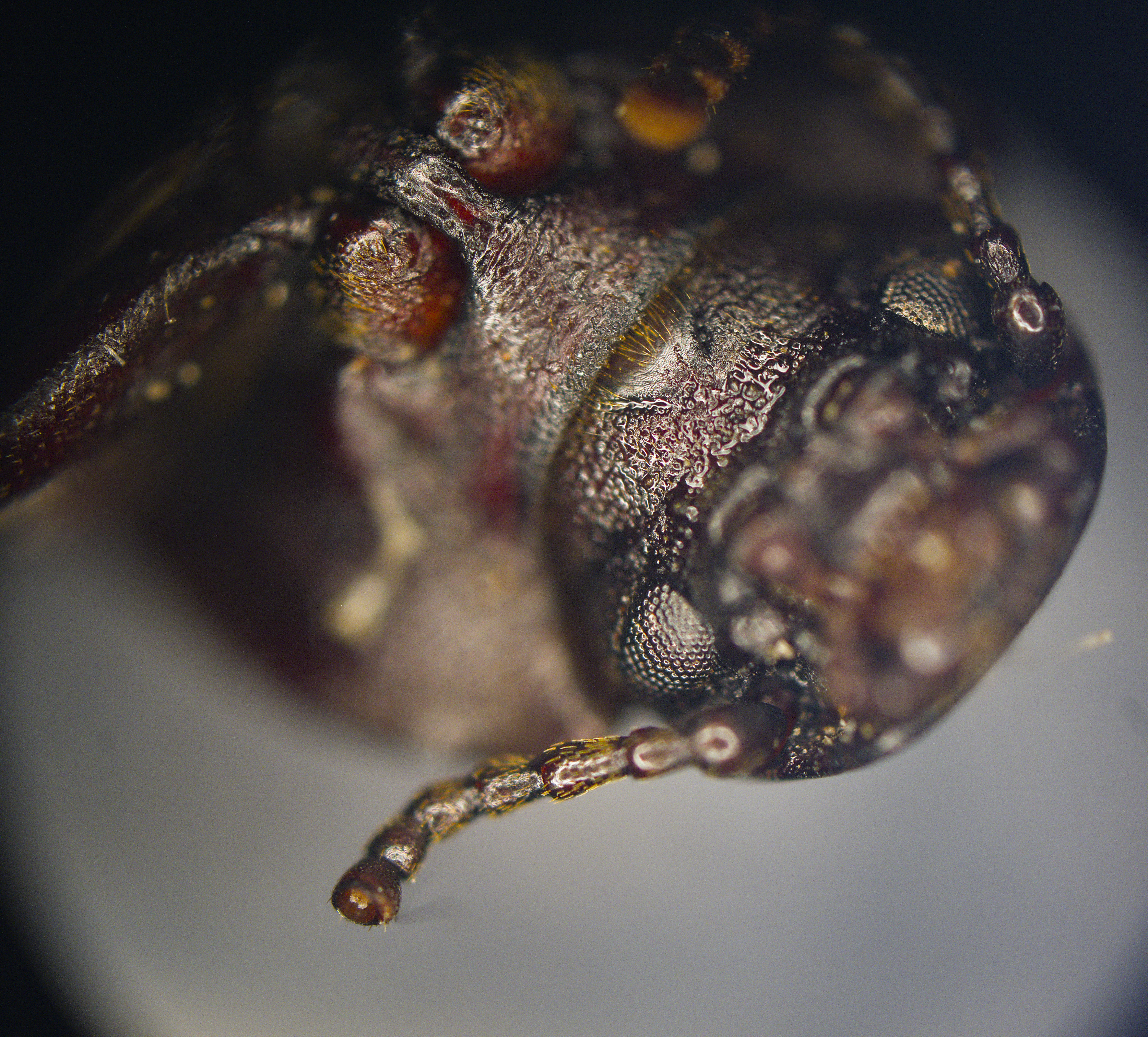
These images captured with 20x objective. I tried to get closer but working distance of 50x objective is so small that front of the objective was hitting the wirebonds coming off the chip!
Red cells of plan leaf: Depth of field is super small and images like this must be stacked over many frames with fine-tuned displacement to produce nice sharp object images.
Random dead bug I found in the basement, focused on the eye:
Test images with bright field light , U180 ASIC
Test images with bright field light , U180 ASIC with DIC
Test images of Pixel 3a OLED display
50x magnification:
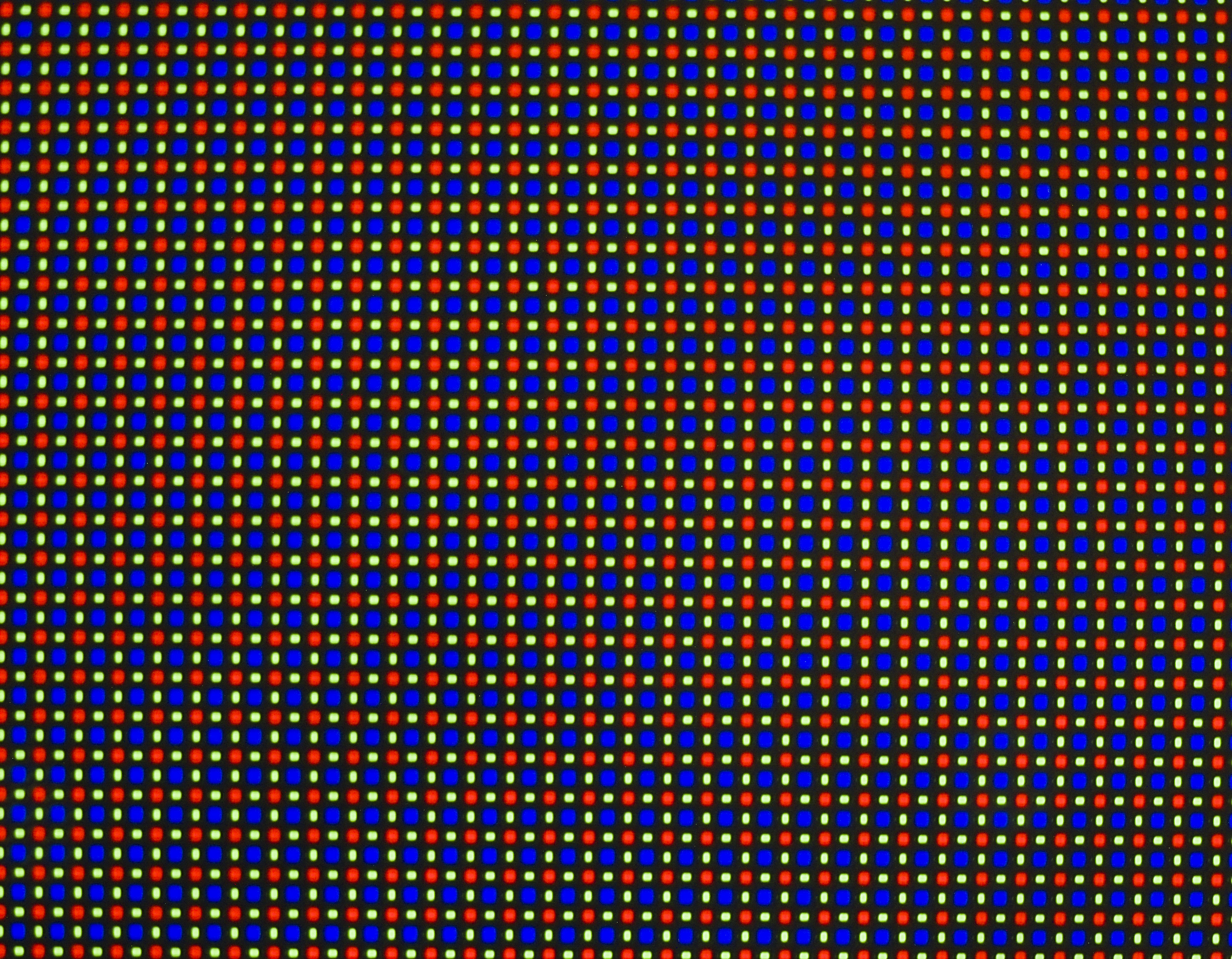
100x magnification:
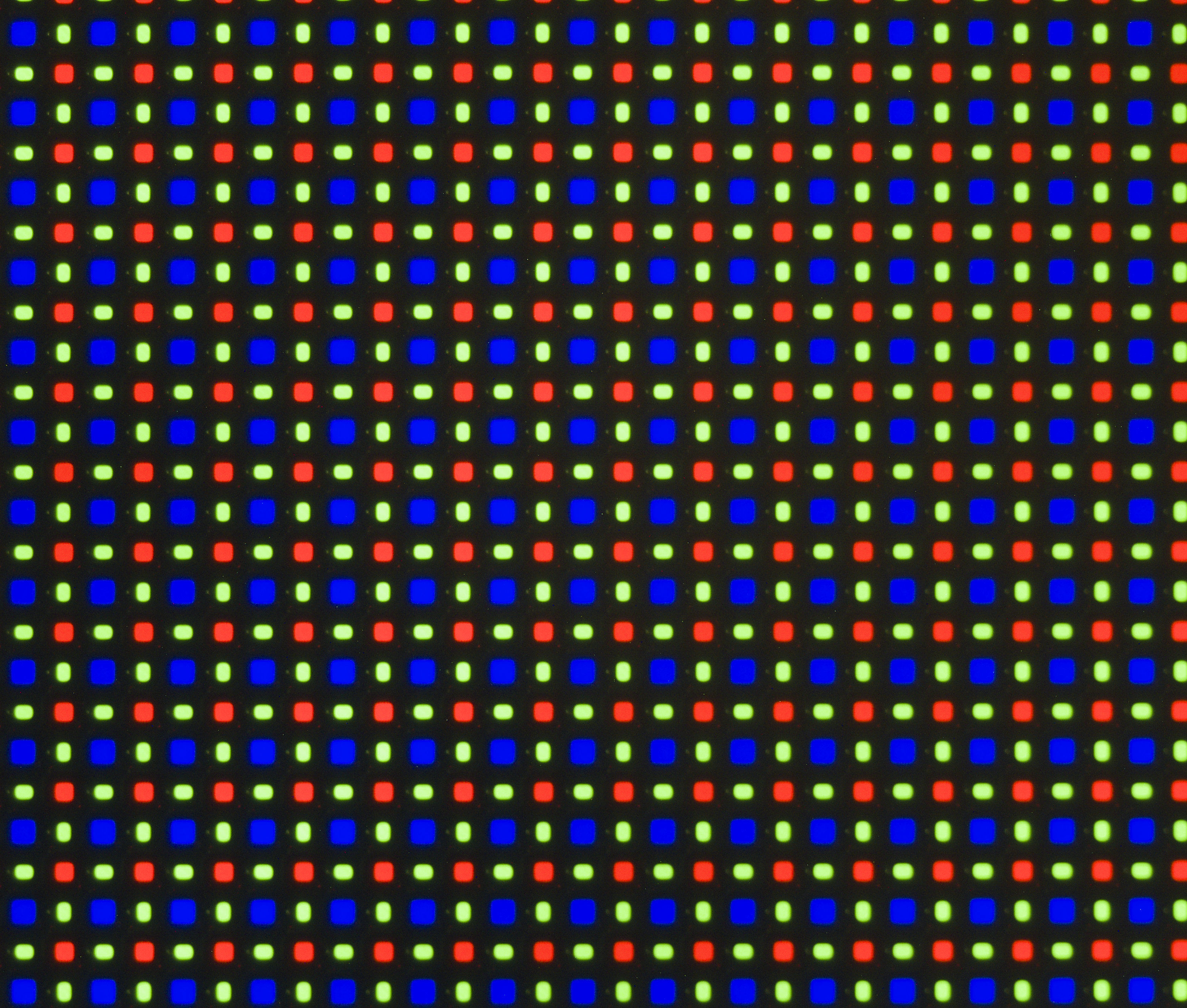
200x magnification:
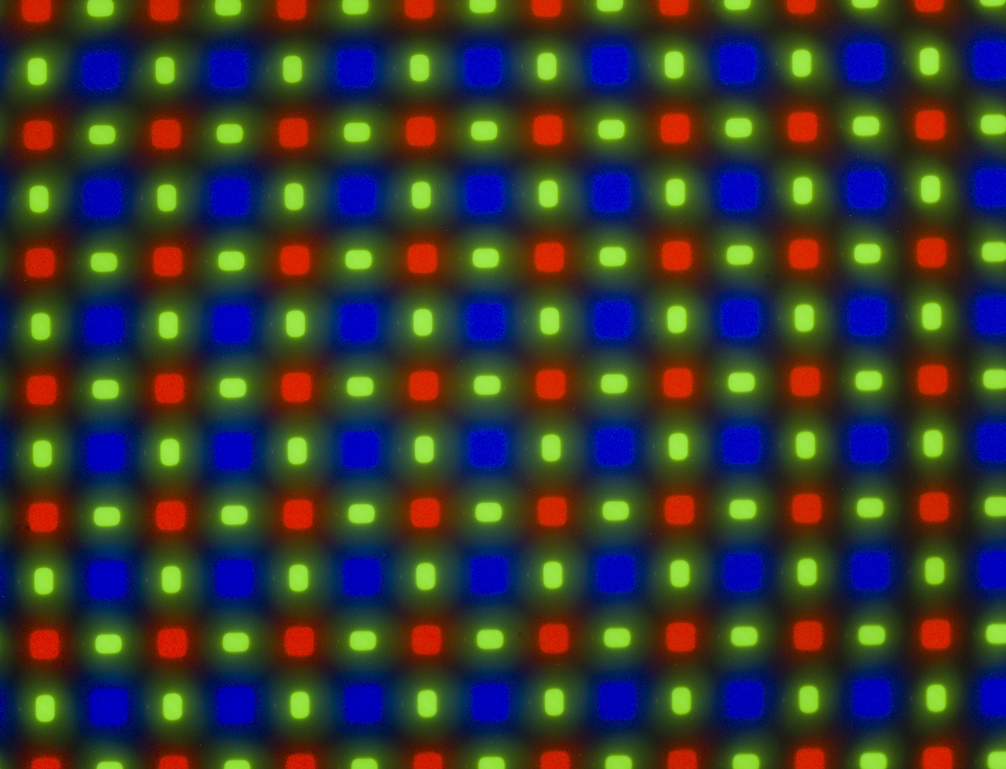
It was impossible to try any higher magnification as objective was hitting front glass of phone at this point.
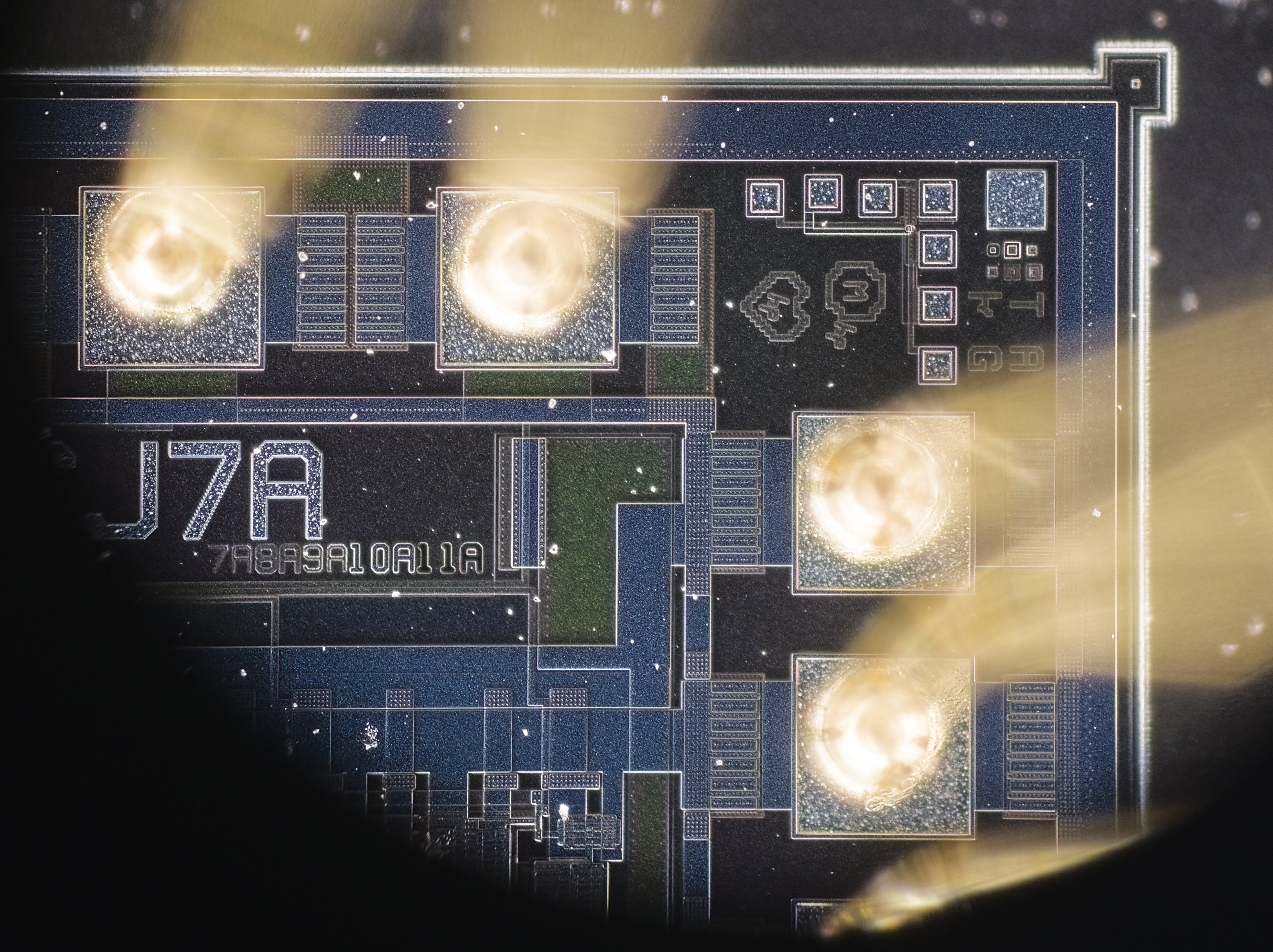
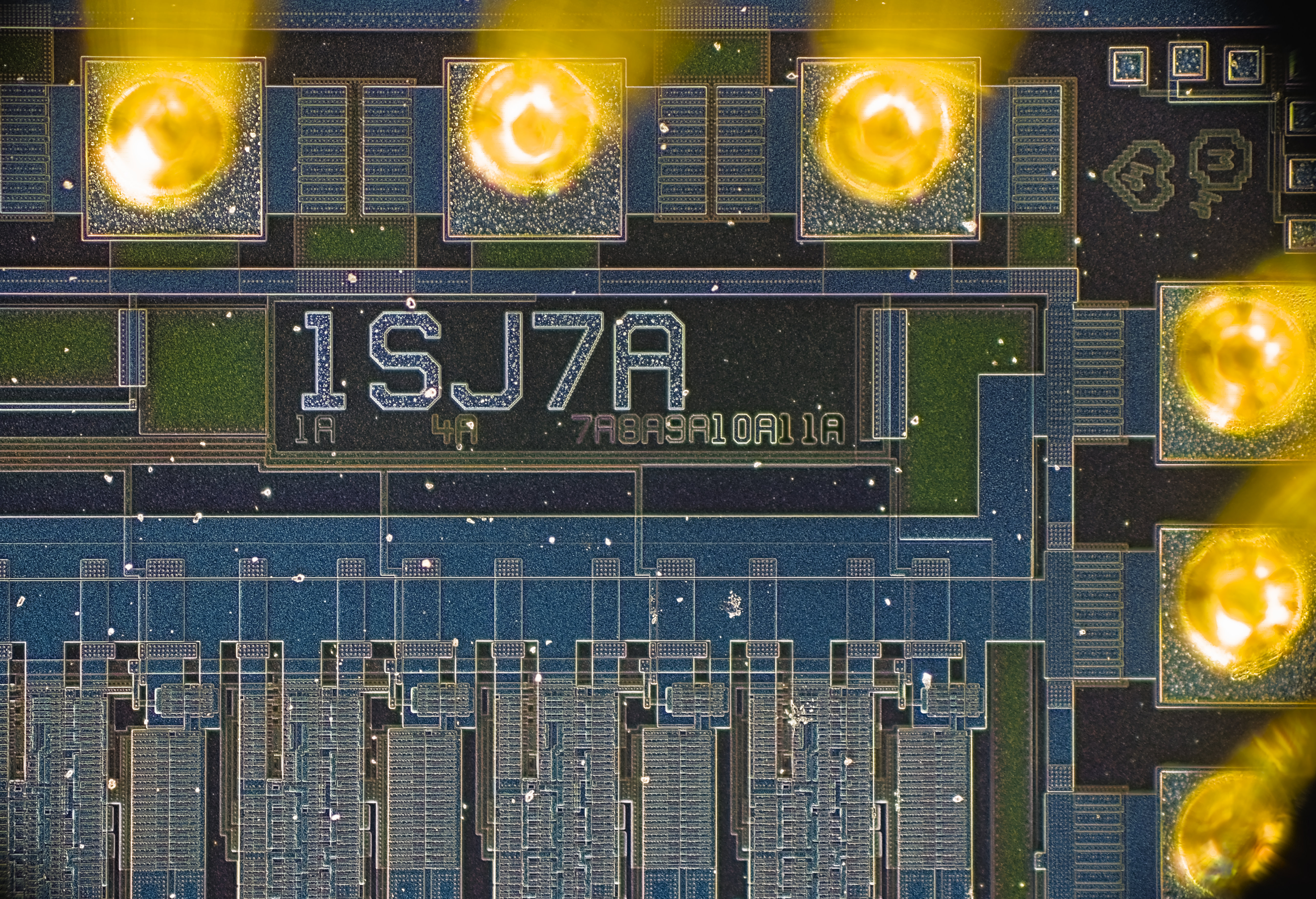
Tests with zener IC photographs
Now let’s take a look on ADR1000 DC voltage ovenized zener IC die close up under this microscope. All photos below captured with Fujifilm X-H2S camera without lens, just with small spacer adapter (empty), sitting on top camera port of Axiotron. Let’s start with 20x objective with DIC engaged. Single photograph:

One can clearly see that depth of focused area is very narrow and because chip and optical plane are not parallel only tiny sliver of the die is in focus. Not very useful. But if we have bit more time and ability to carefully move focal plane up and down across the chip, it’s possible to capture a sequence of these tiny line focused images. This method called focus-stacking and is very common way to process photographs to improve depth of field. Methods like this are used in microscopy a lot and even in daily photography for landscapes and product imaging. Many modern cameras allow to perform focus-stacking or simplify images collection to some extent.
Now result of computing power processing applied to 42 images are shown below:

Much better result, be sure to click on high resolution file to enjoy the glory. Here’s 100% pixel crop of center area as well:

Now we can swap the objective to 50x DIC and repeat the same for 500 times magnification images.
Single image:
Focus stack result of merged 25 images:
And the same process with 100x objective. I had to bend outer edges of TO can metal a lot to make chip die go superclose to the objective surface, less than 0.3 mm away. Visually it looked like IC is inside of the lens already :) Single image shows lot of dirt and dust around.
Focus stack of 27 images at 1000 magnification:
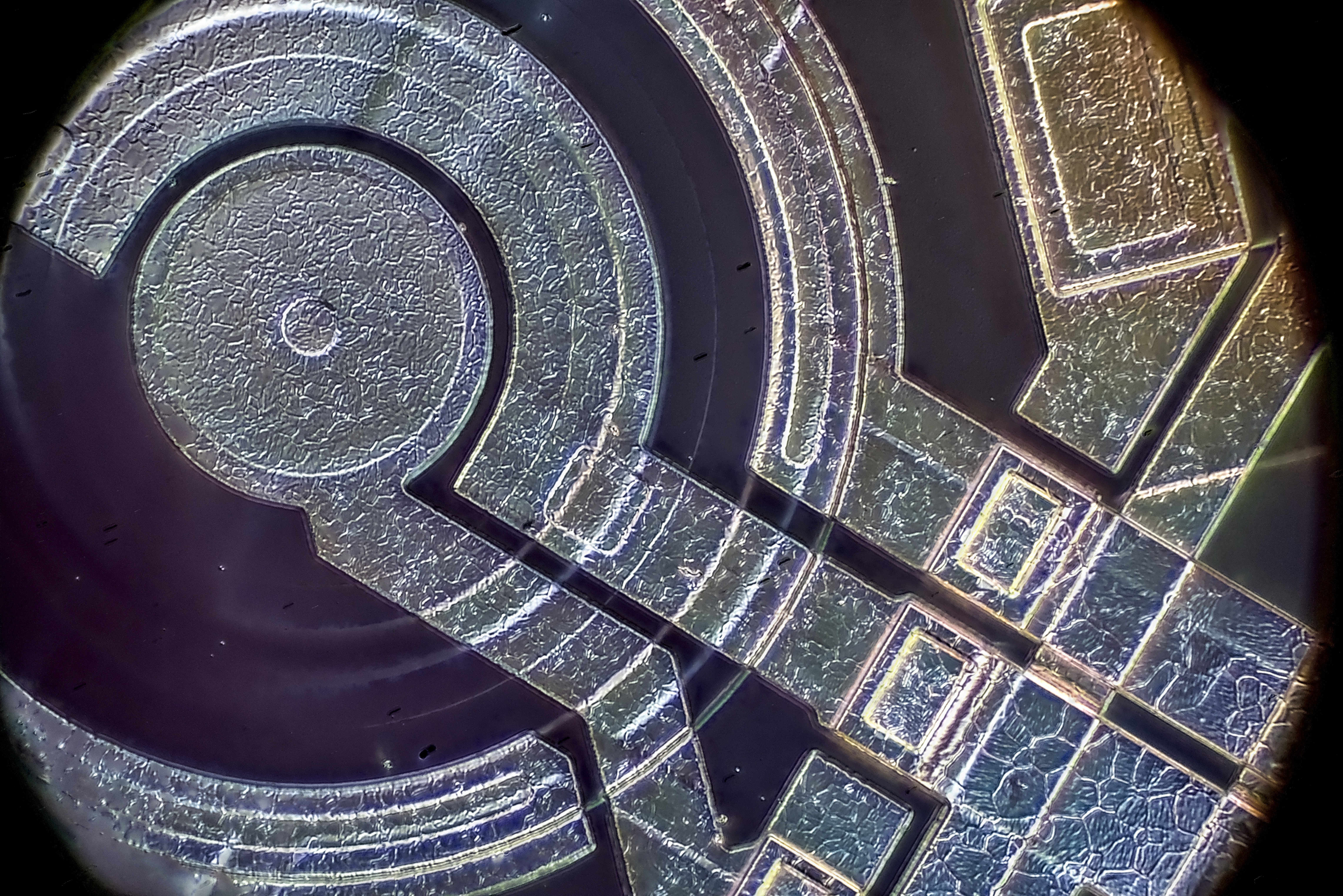
LT1016CS8
Full resolution photograph is available on click as usual. Masks of this particular IC were designed in 1990 and we can see good old Linear Technologies logo. Chips were heated to 400-500 °C temperature with hot air gun, broken off mechanically and dies extracted from the packages. Photographs was captured with 200x magnification in DIC microscopy mode. This is a technique used to enhance the contrast and surface rendering. DIC works on the principle of interferometry to gain information about the optical path length of the sample, to see otherwise invisible features like a tiny thickness variation.
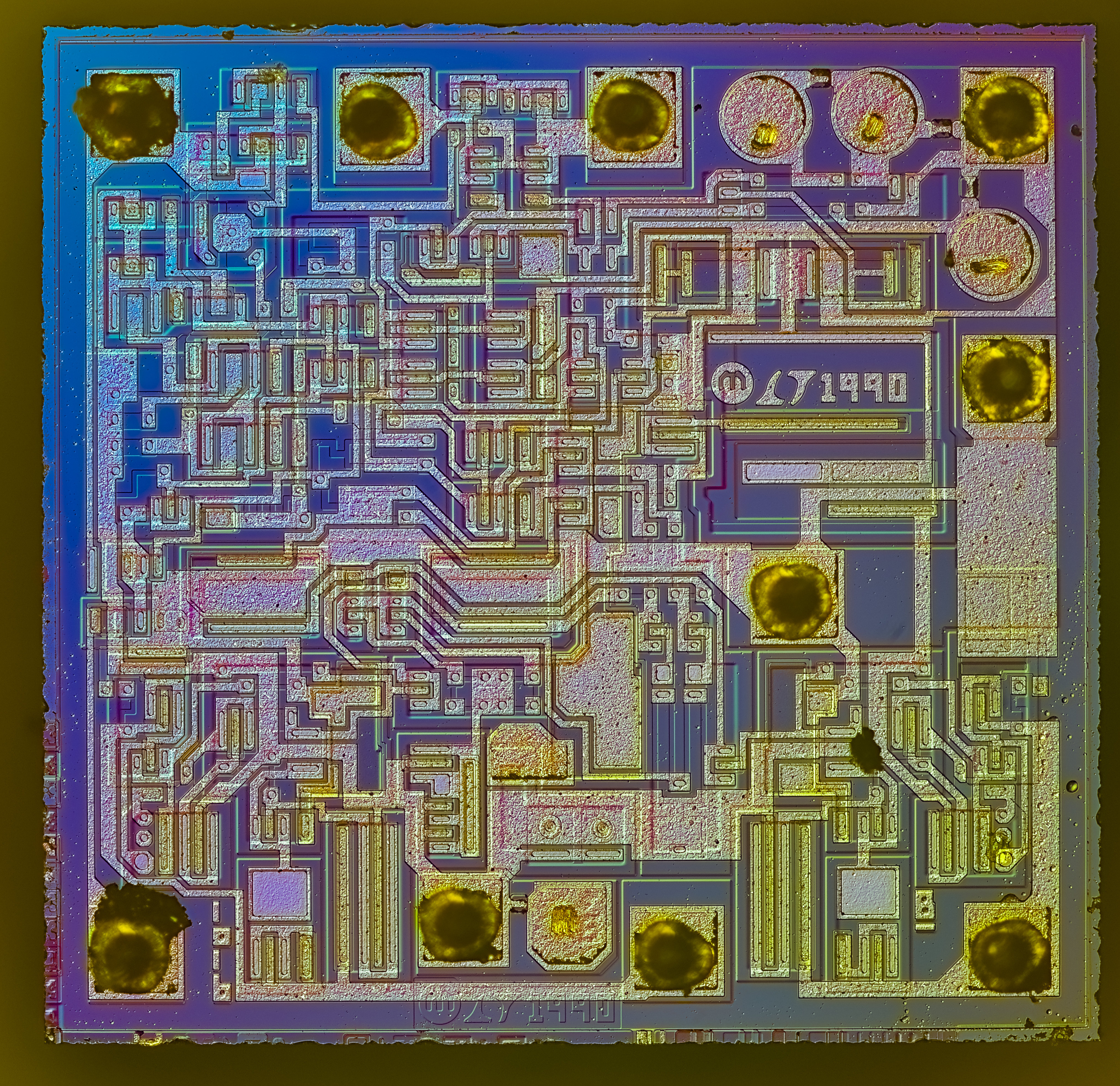
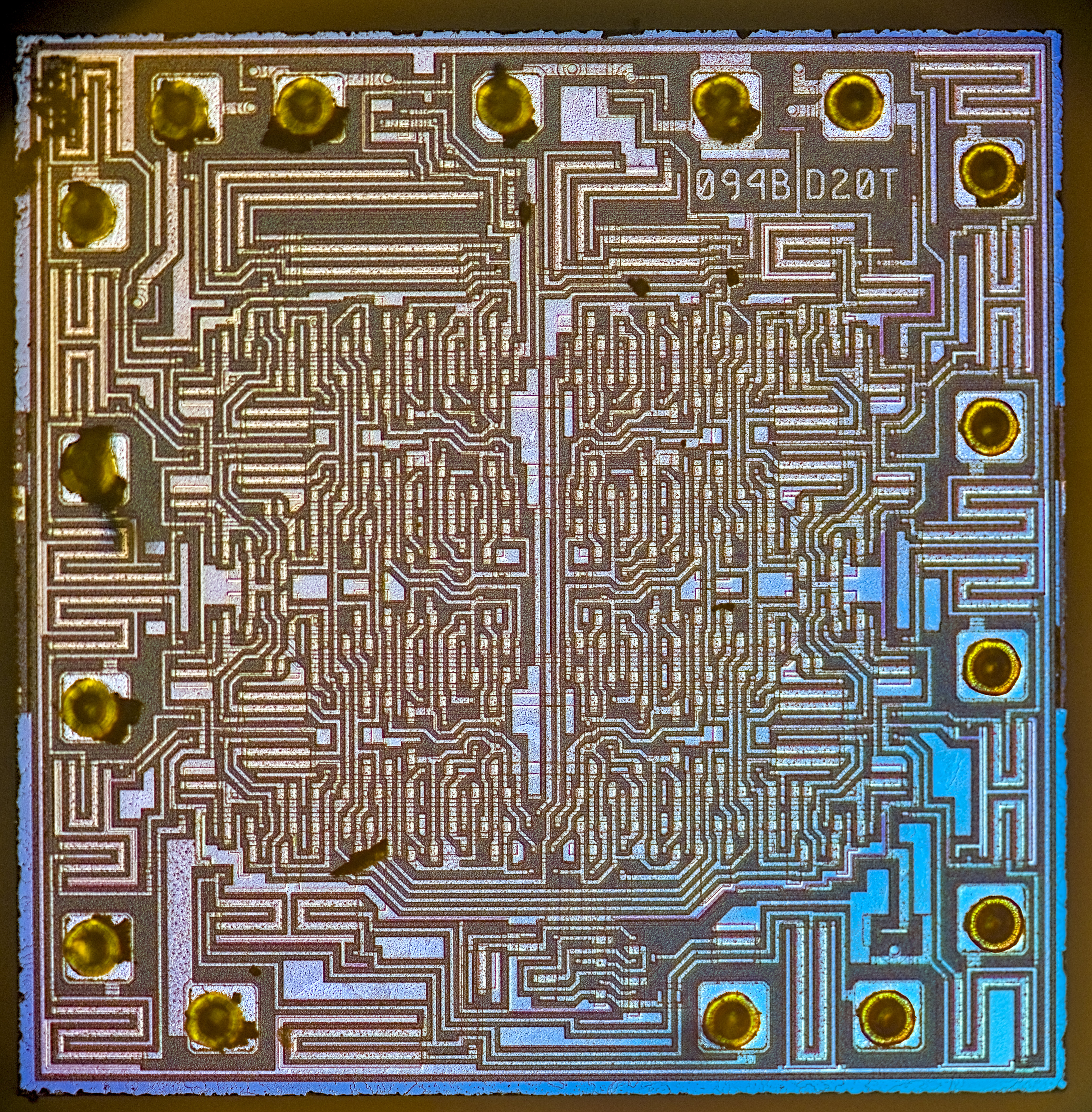
MC14094B shift register commonly used in many Keithley instruments
Zeiss LD Epiplan 50x/0.50 (P/N 442850)
To capture microscope photographs of tall and non-flat specimens I’ve needed longer working distance objective. To try this out I’ve aquired Zeiss 442850 with RMS mount thread.
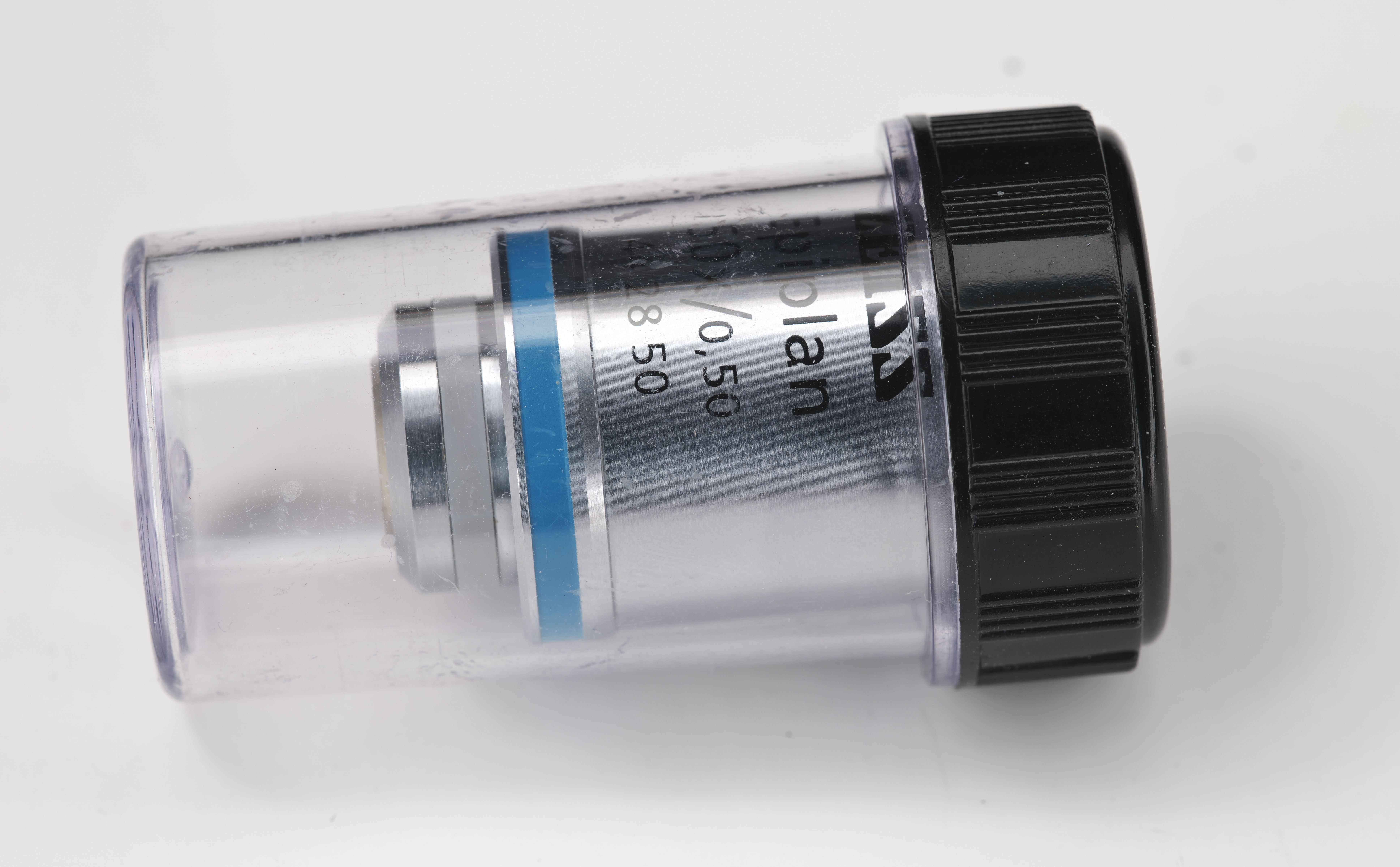
This is a bright-field only objective without support of DIC or darkfield. Objective was acquired used from secondary market.
LD Epiplan 50x/0.5 is designed for use without immersion, has parfocal length 45 mm and has impressive 7 mm of free working distance.
With a simple RMS-M27 adapter ring this objective can be easily coupled on Axiotron here. Large working distance enables focusing nicely on rather thick objects:
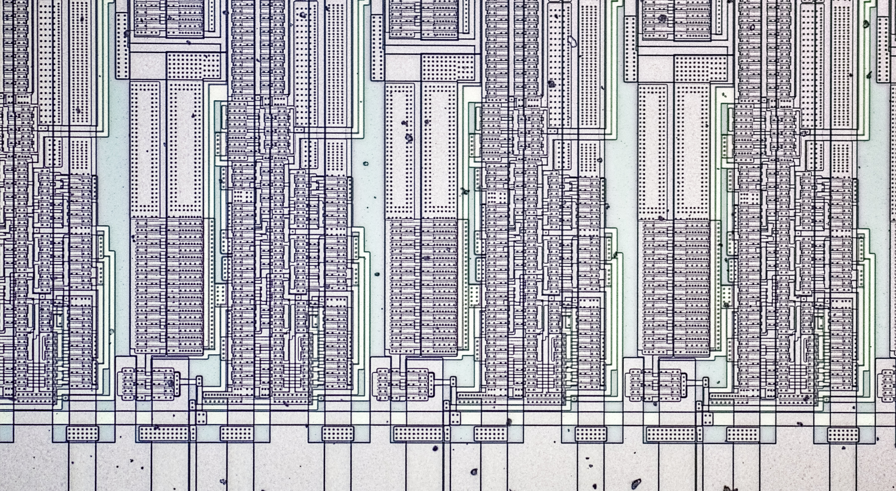
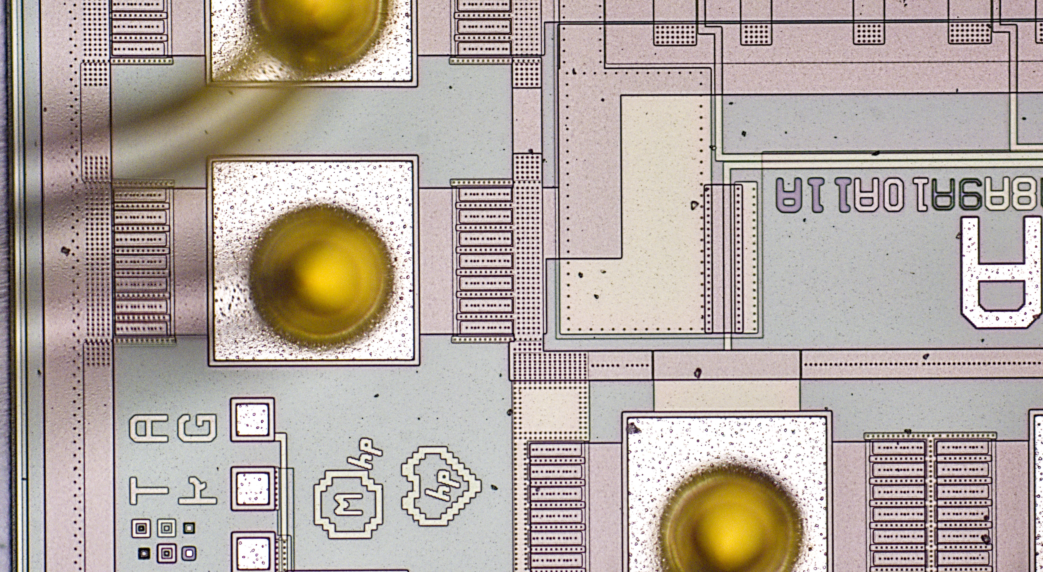
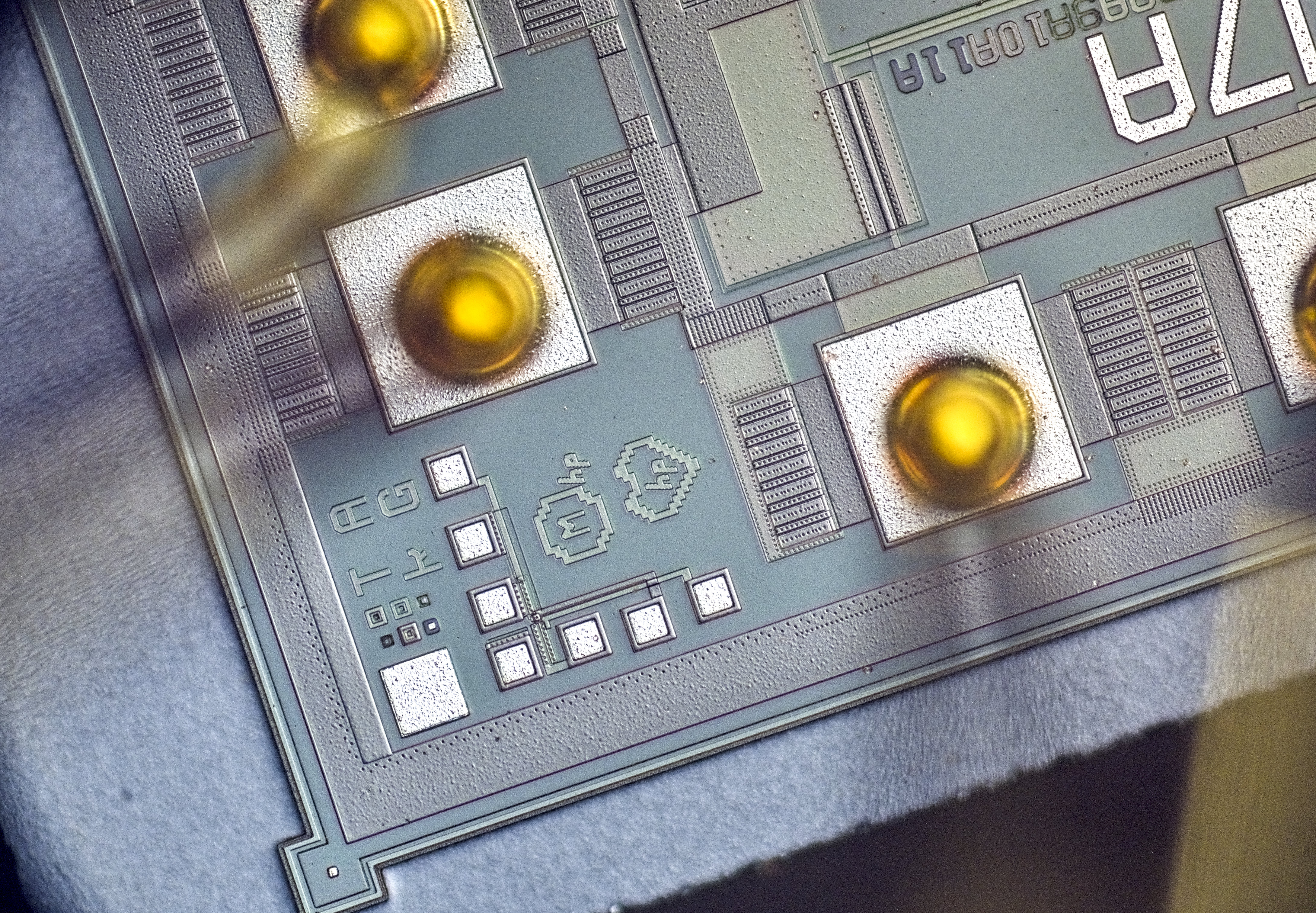
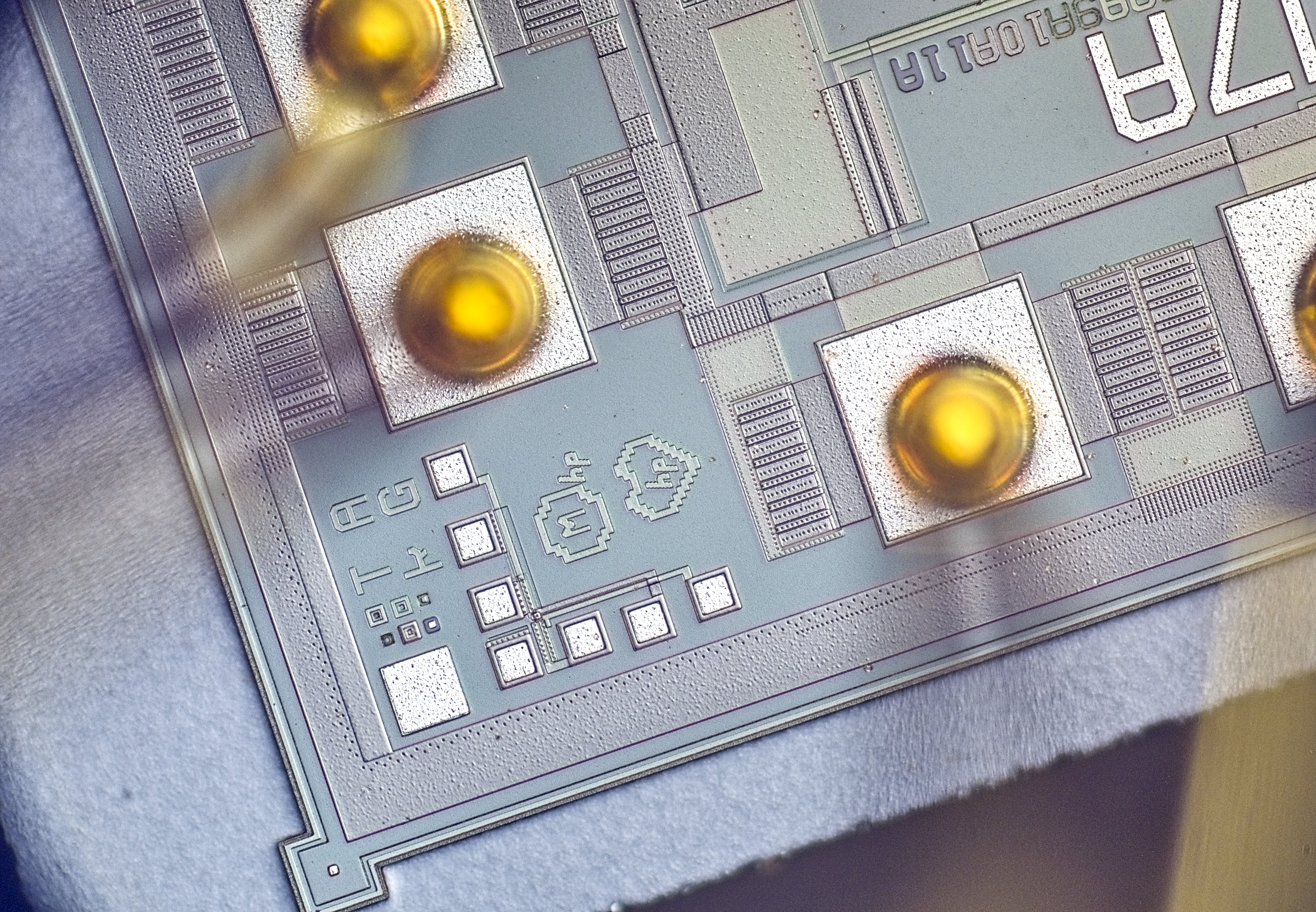
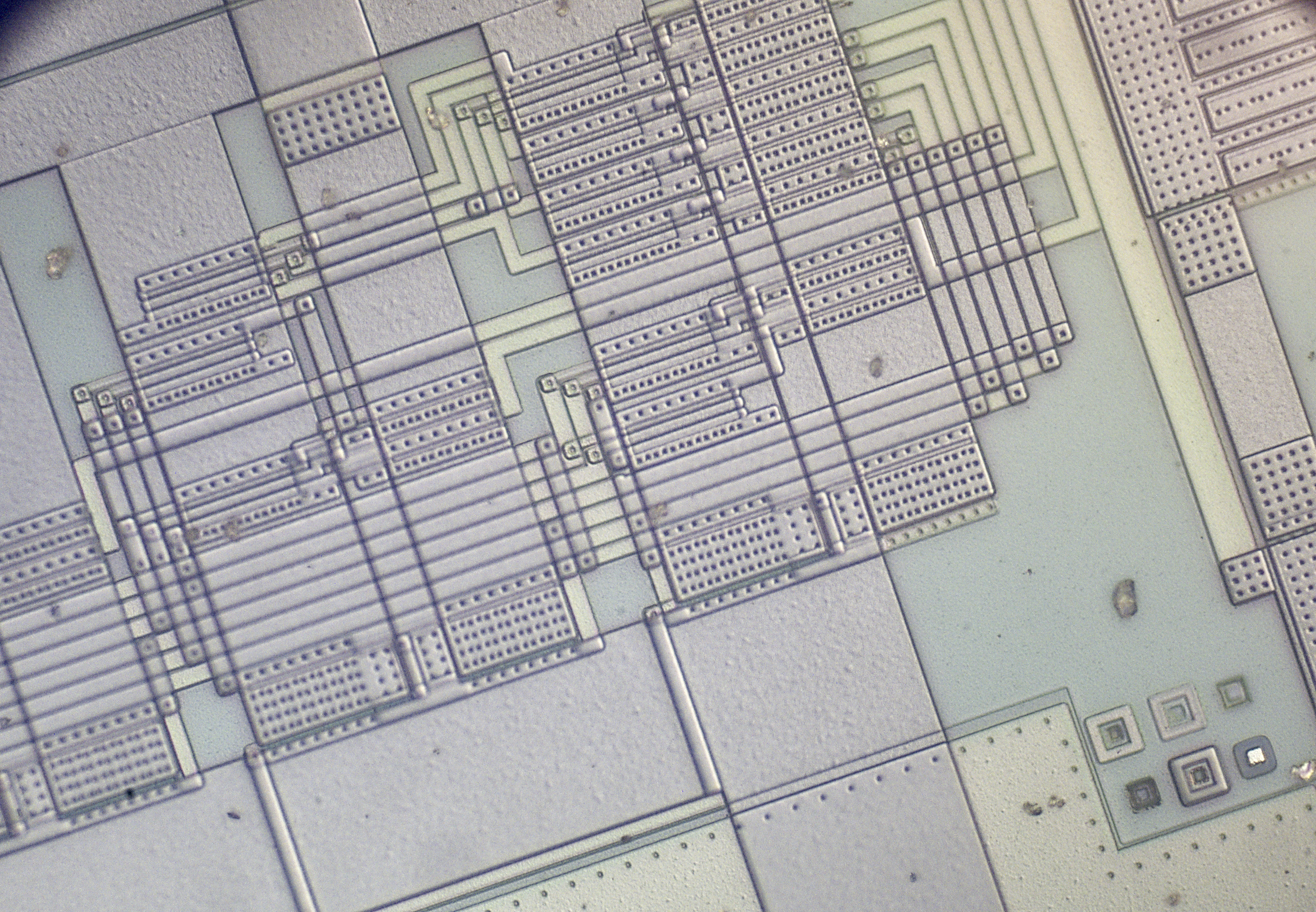
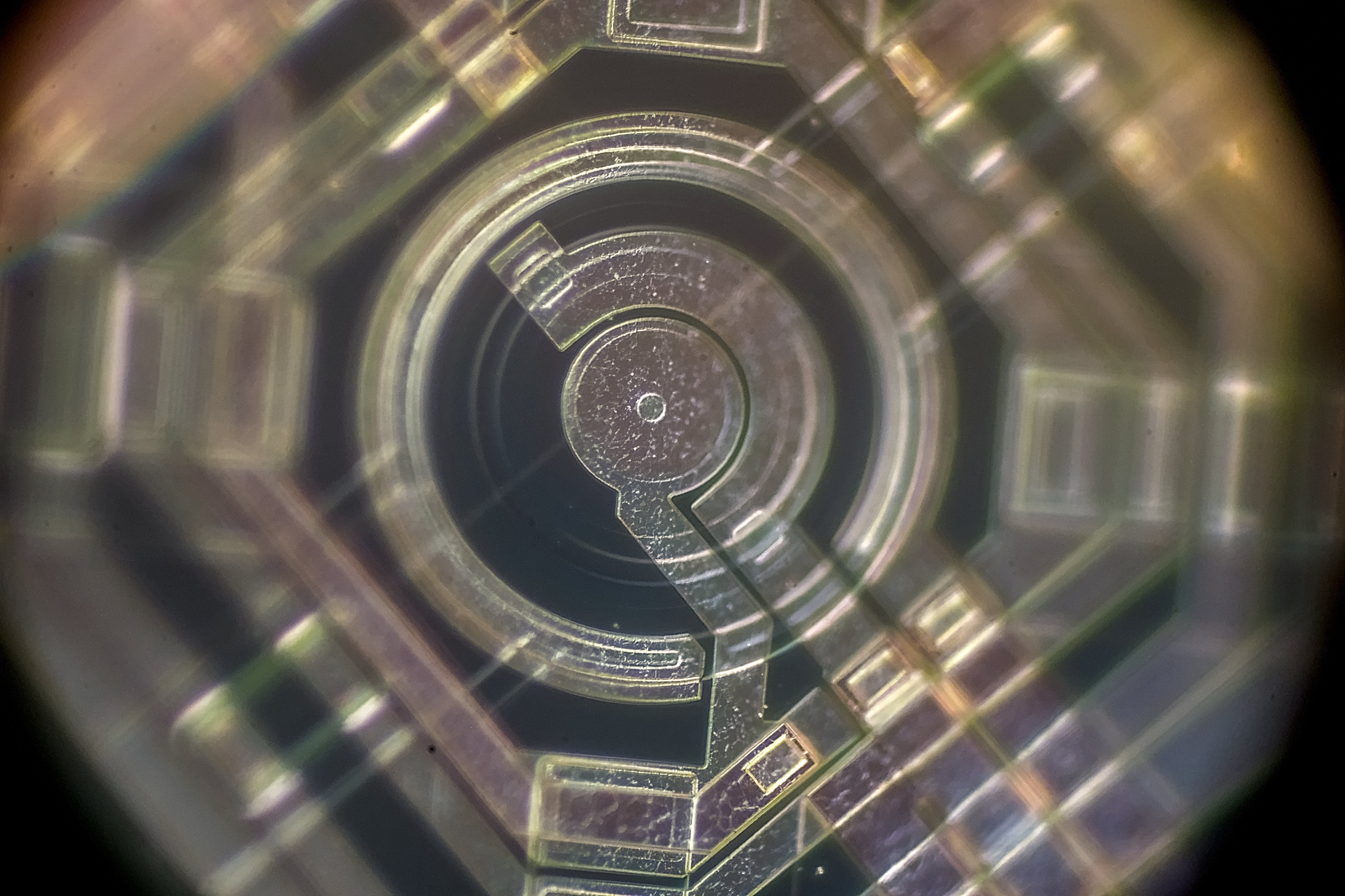
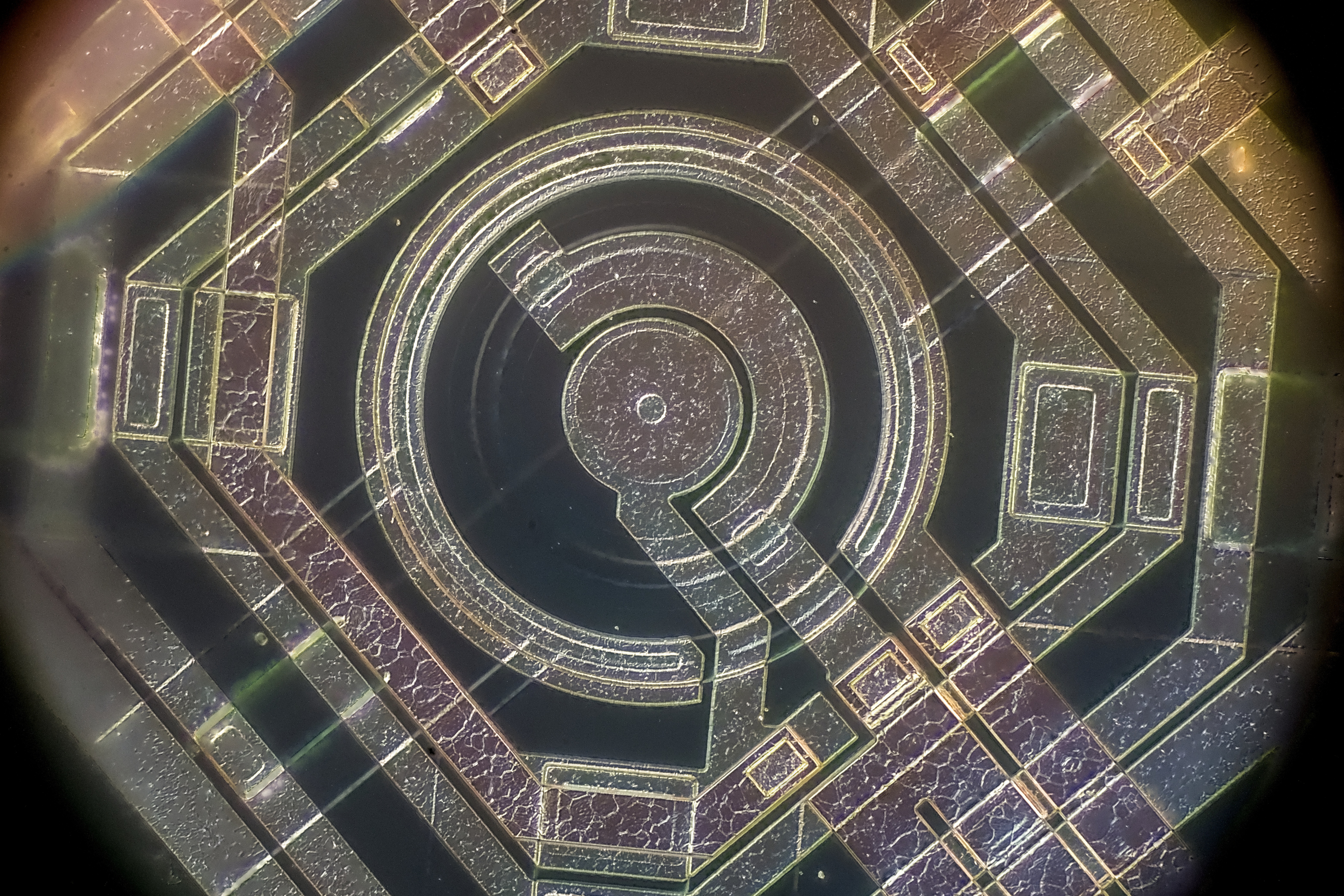
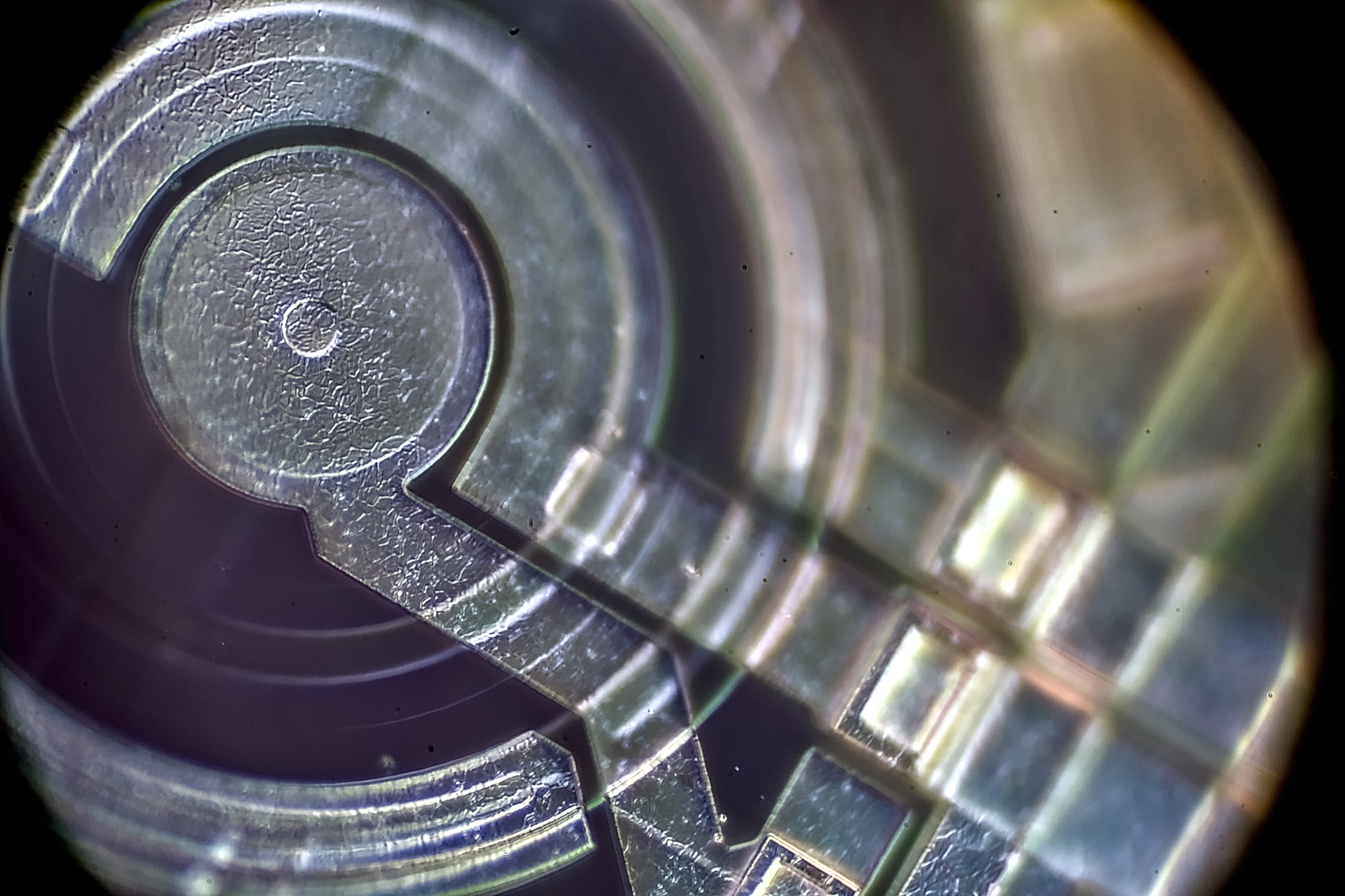
Traditional 3458A U180 logic die photo:
Single photograph with LD 50x/0.5:

Here’s 20x Epiplan-Neofluar 20x/0.50 objective working distance for comparison, often impossible to reach focal point for non-flat objects:

And same area with Neofluar 20x standard objective:

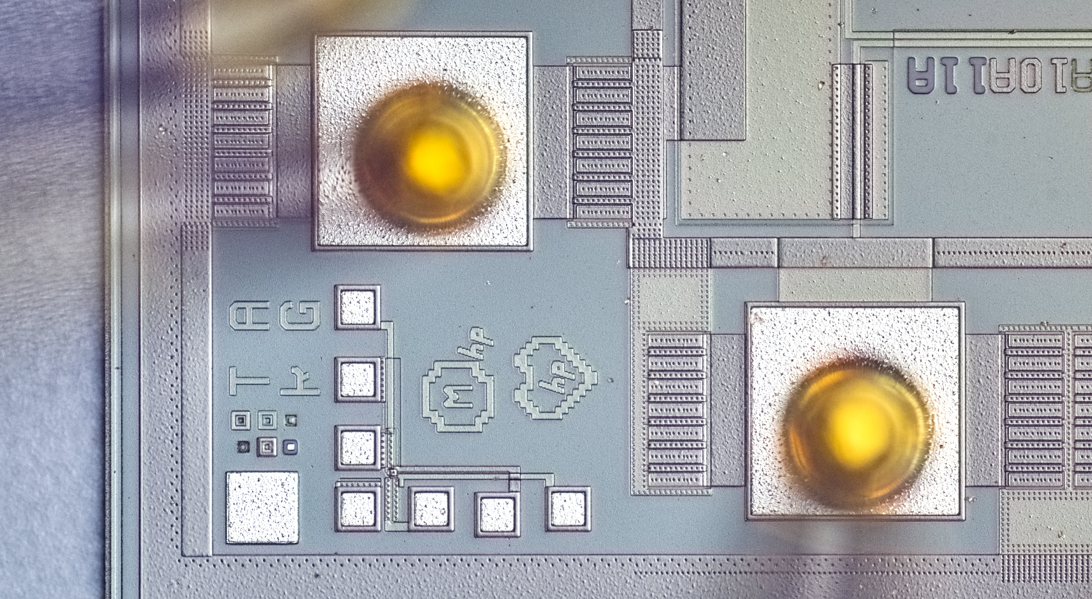
ADR1000 zener core:
Focus stacks combined from multiple images:

ALTERA Stratix II EP2S130F1020 high-end FPGA, destroyed chip pieces extracted with heat:
Cracked slices of the chip reveal inner layer structures and copper line connections:
BB operational amplifier section:
Summary
…
Projects like this are born from passion and a desire to share how things work. Education is the foundation of a healthy society - especially important in today's volatile world. xDevs began as a personal project notepad in Kherson, Ukraine back in 2008 and has grown with support of passionate readers just like you. There are no (and never will be) any ads, sponsors or shareholders behind xDevs.com, just a commitment to inspire and help learning. If you are in a position to help others like us, please consider supporting xDevs.com’s home-country Ukraine in its defense of freedom to speak, freedom to live in peace and freedom to choose their way. You can use official site to support Ukraine – United24 or Help99. Every cent counts.
Modified: Feb. 5, 2026, 4:26 a.m.