Contents
- Intro
- Disclaimer
- Exterior and overview
- Diagnostics and inspection
- Teardown
- Performance test
- Conclusion
Intro
As was predicted not very long time ago, complete Fluke 720A standard got into out hands finally. This device is a fully passive Kelvin-Varley Divider, formed by network of precision ultra-stable wire-wound resistors arranged as voltage divider circuit. Seven decades with 12-position rotary switch in each allow to set arbitrary division ratio of an input voltage.
Fluke 720A design was developed and tested around 1966, but even today, 50 years after, it’s still one of favorite metrology tools and often used as excellent linearity mechanical DAC. This KVD able to work well where modern digital ICs cannot meet required 0.1 PPM performance level. Fluke 720A’s base linearity is surpassed only by few instruments, such as 8½-digit HP 3458A DMM. During design and calibration Fluke had used primary standards, such as cryogenic JVS to characterize and evaluate these machine’s accuracy.
Specification sheet
High performance of this KVD unit can be revealed by it’s specifications. Brief summary table presented here, based on Instruction Manual.
| Specification | Fluke 720A | Unit | Condition |
|---|---|---|---|
| Ratio range | 0 to 1.0 or 0 to 1.1 | Based on input tap | |
| Resolution | 0.1 of input | ppm | Set by 7 decades |
| Maximum input voltage 1.0 | 1000 | VDC | 1.0 Input terminal |
| Maximum input voltage 1.1 | 1100 | VDC | 1.0 Input terminal |
| Breakdown voltage 1.0-1.1 input | 200 | V | Damage limit |
| Breakdown current | 11 | mA | Input or output |
| Breakdown voltage | 2000 | VDC | |
| Input resistance | 100 ±50 ppm | kΩ at +25°C | at 1.0 Input |
| Input resistance | 110 ±50 ppm | kΩ at +25°C | at 1.1 Input |
| TCR of input resistance | ± 1/°C | ppm | Maximum |
| Thermal voltages | ± 0.5 | µV | Maximum |
| Maximum output resistance | 66 | kΩ | |
| Maximum input power | 10 (11) | W | on 1.0 input (1.1 input) |
| Absolute linearity | ±0.1 of input | ppm | on dial 1.1 to 0.1, at calibration temp |
| Abs.linearity stability | ±1.0/input/year | ppm | on dial 1.1 to 0.1, without self-cal |
| Short term stability | 0.1 at 30 days | ppm | Stable TENV ±1°C, VIN < 100VDC |
| Linearity temperature coefficient | ±0.1/input/°C | ppm | on dial 1.1 to 0.1 |
| Linearity Power coefficient | ±0.2/input/watt | ppm | on dial 1.1 to 0.1 |
| Maximum end errors | 0.004 of input | ppm | Zero error, output low |
| Maximum end errors | 0.05 of input | ppm | Zero error, output high |
| Maximum end errors | 0.05 of input | ppm | Full-scale error |
| Operating temperature range | 0 to 50 | °C | |
| Temperature linearity derating | 0.1 | ppm/°C | if TENV > 35°C |
Table 1: Specification summary for Fluke 720A
So essentially, if we skip important construction and design details for sake of simplicity, Fluke 720A is just a fancy potentiometer.
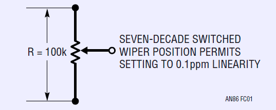
%(imgref)Image courtesy Linear Technologies Application Note 86 by Jim Williams, Jan 2001
This instrument, as well as alternative IET KVD-700 (which is same design and specification as the Fluke 720A) has base price tag of $28000 USD. Phrase “too expensive, if you asking” apply here well.
Instruction manual provide use, calibration and servicing information for the unit. It’s still available from Fluke website.
Disclaimer
Redistribution and use of this article or any images or files referenced in it, in source and binary forms, with or without modification, are permitted provided that the following conditions are met:
- Redistribution of article must retain the above copyright notice, this list of conditions, link to this page (/fix/f720a/) and the following disclaimer.
- Redistribution of files in binary form must reproduce the above copyright notice, this list of conditions, link to this page (/fix/f720a/), and the following disclaimer in the documentation and/or other materials provided with the distribution, for example Readme file.
All information posted here is hosted just for education purposes and provided AS IS. In no event shall the author, xDevs.com site, or any other 3rd party, including Fluke be liable for any special, direct, indirect, or consequential damages or any damages whatsoever resulting from loss of use, data or profits, whether in an action of contract, negligence or other tortuous action, arising out of or in connection with the use or performance of information published here.
If you willing to contribute or add your experience regarding any instruments repairs or provide extra information, you can do so following these simple instructions
Exterior and overview
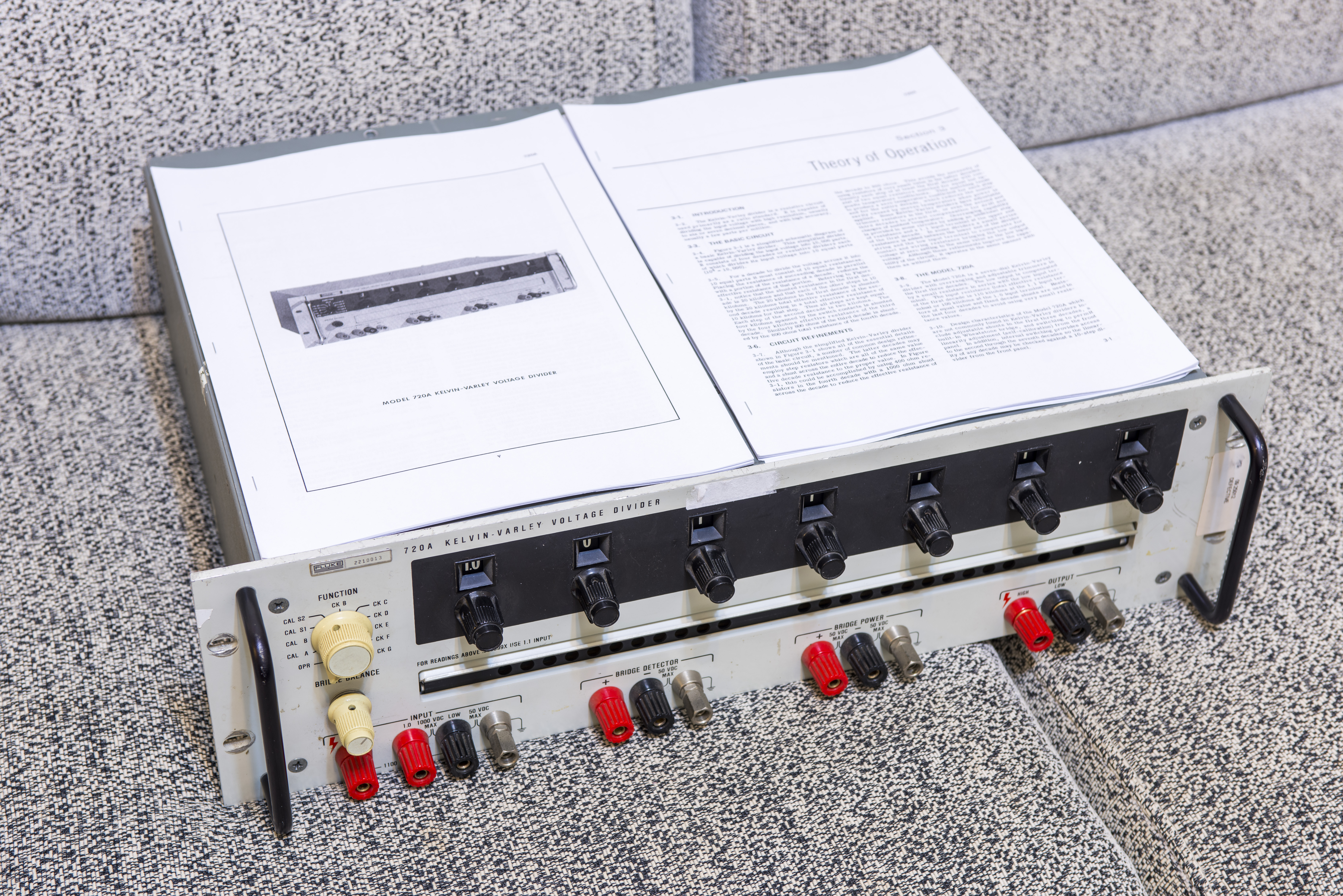
Image 1: Fluke 720A and printed instruction manual
Fluke 720A designed in 3U 19” full-size rack-mount metal chassis with handles and mounting ears as stock option. All operation controls and terminals are located on the front face, making it easy to use.
Input terminals are located at left side near bridge balance pot and operation function switch. Bridge power and detector terminals are used for calibration and linearity testing. Output terminals are on most right corner. LOW output connected to LOW Input via very low compensation resistance shunt.
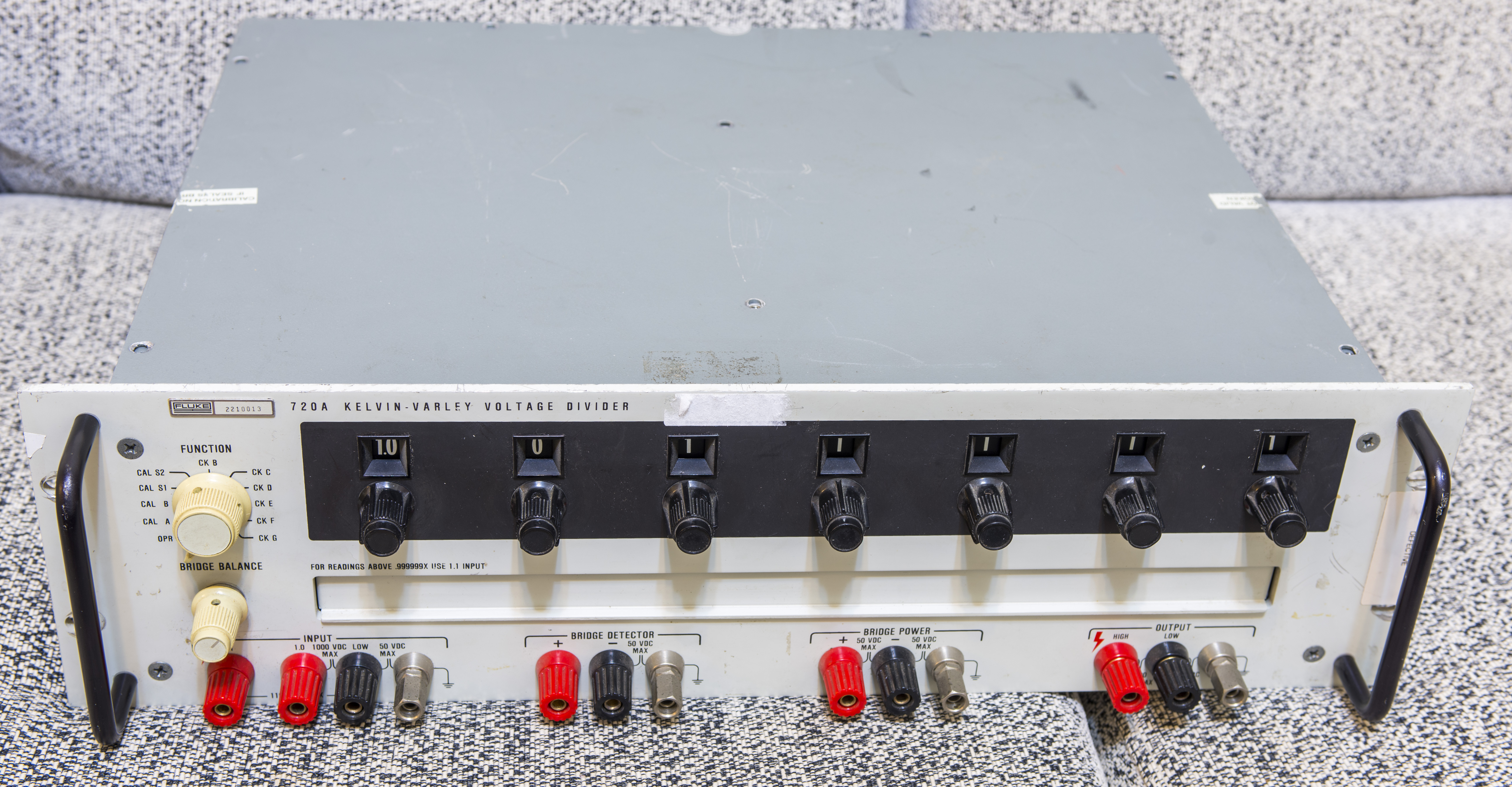
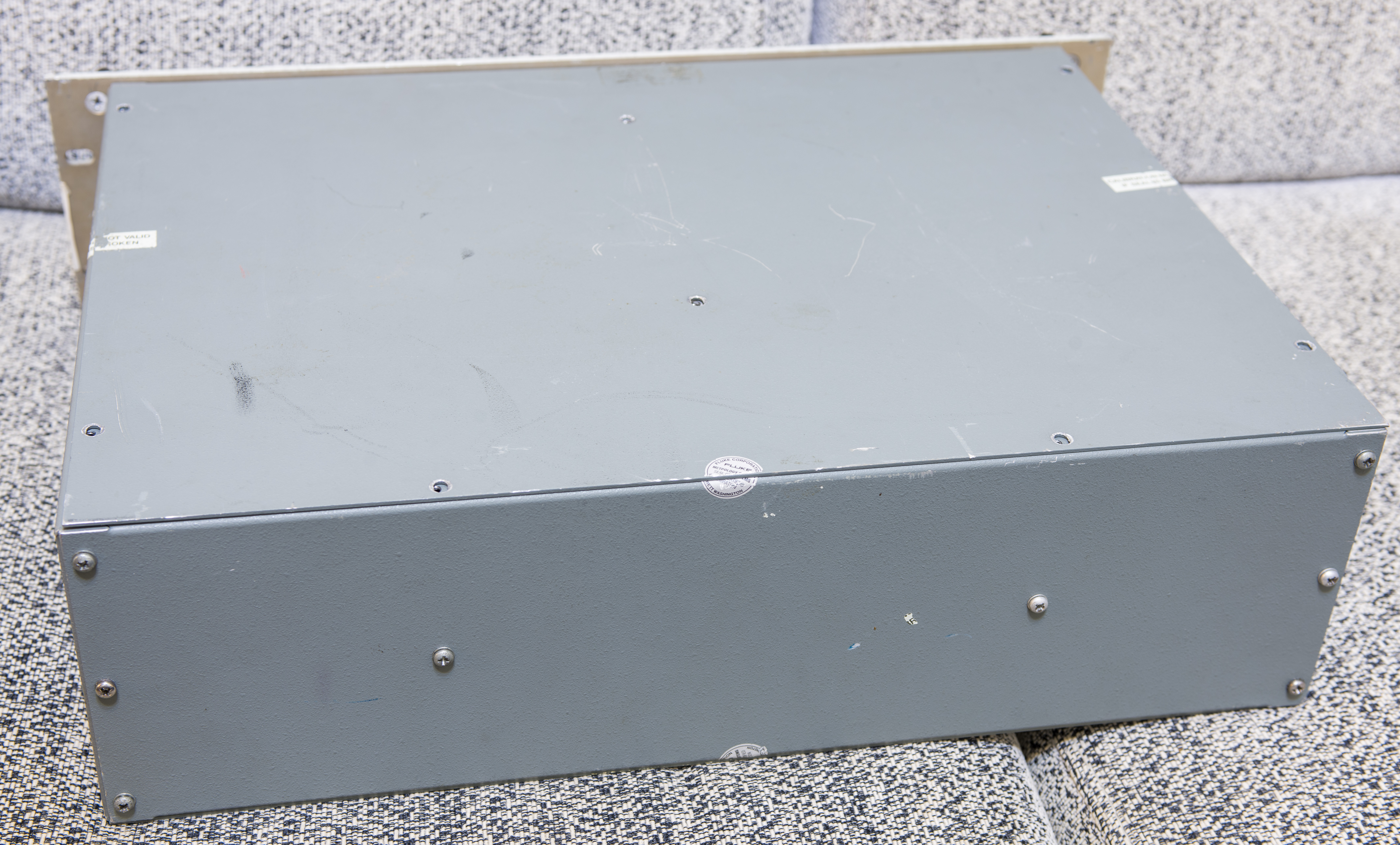
Image 2-3: Fluke 720A front and rear features
There are no connectors, vent openings or anything else on sides and rear of the instrument. This KVD is fully passive device and does not generate any power or signals. Our unit still have old-style Fluke logo, bit yellowed switches and of course dirty connectors:
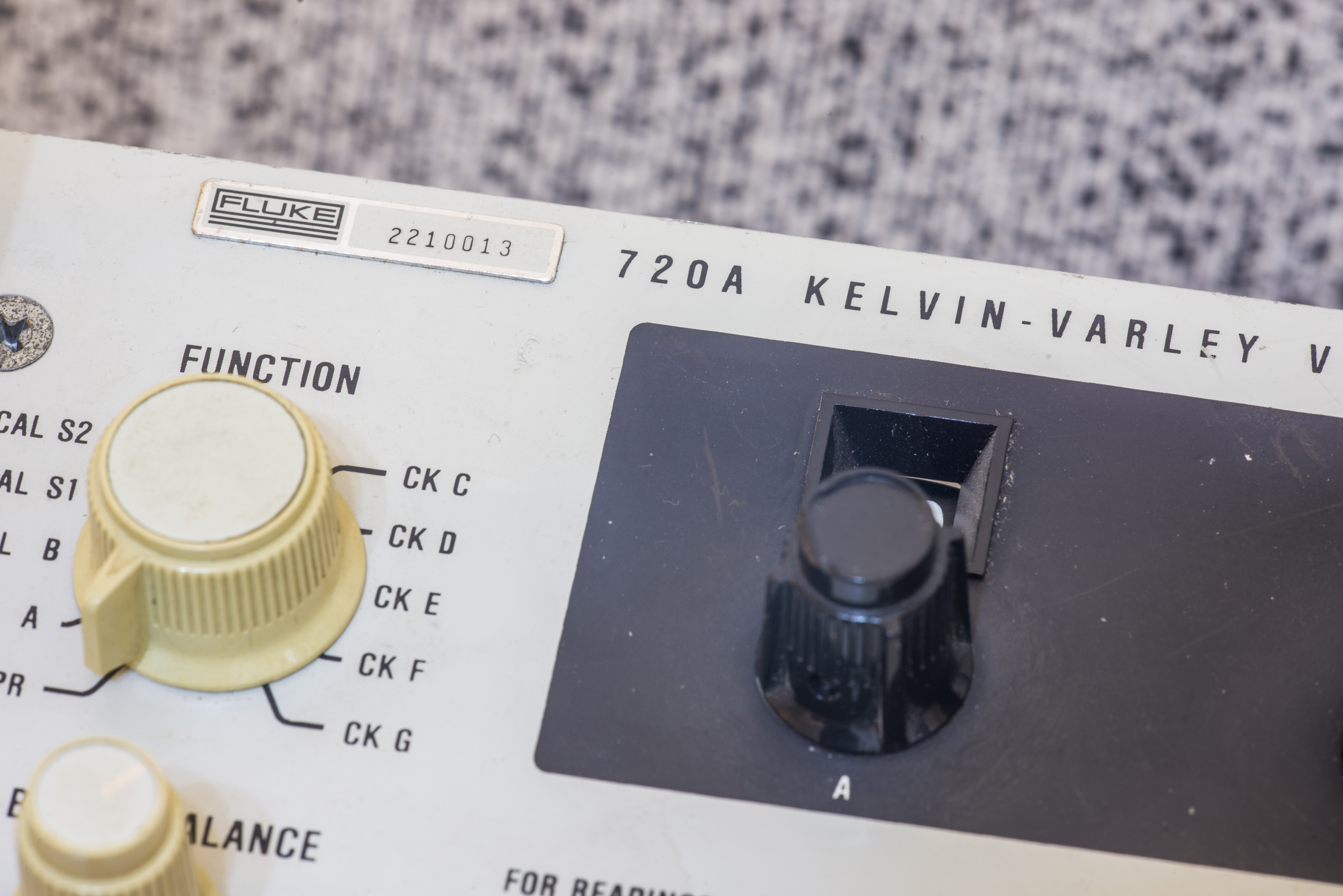
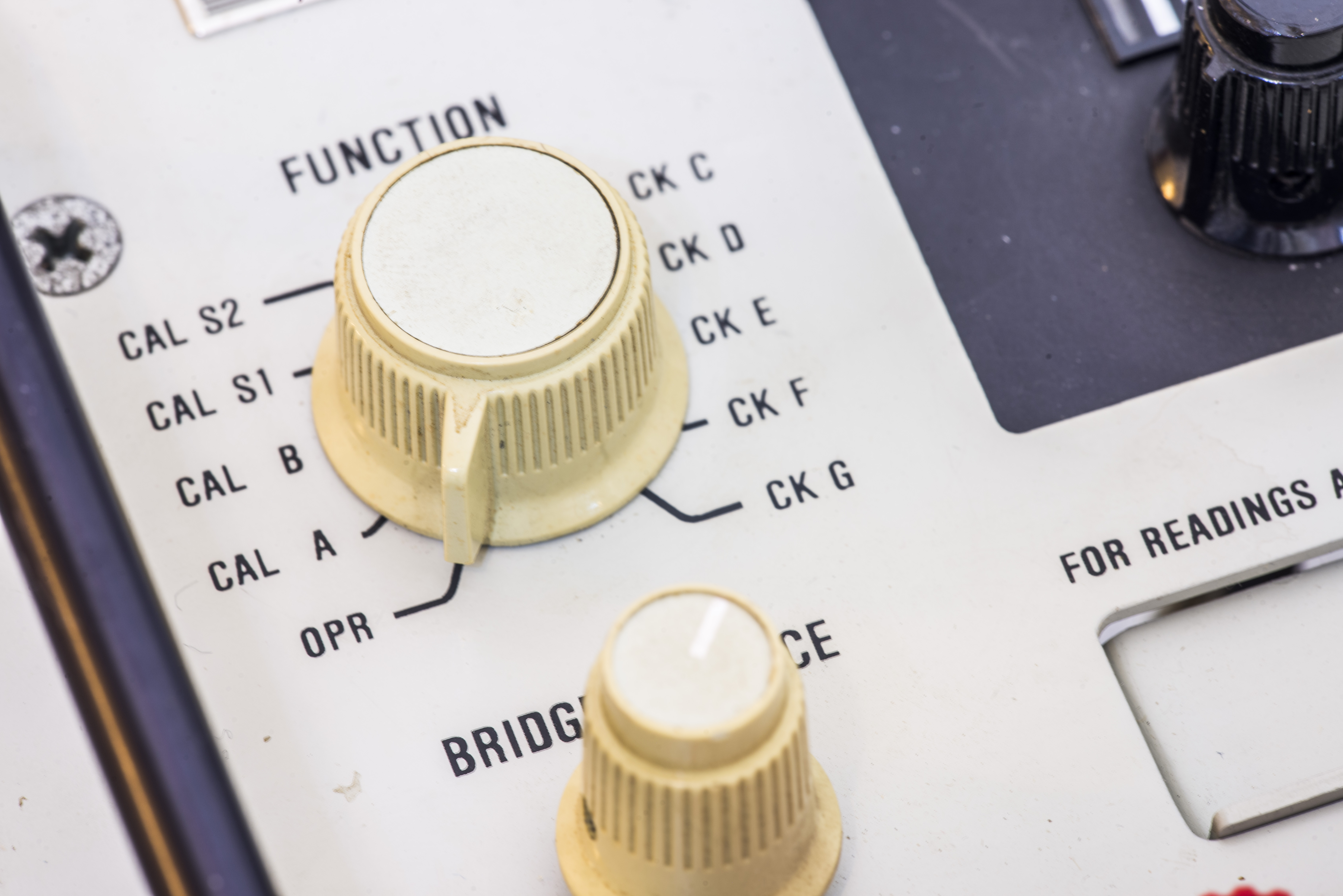
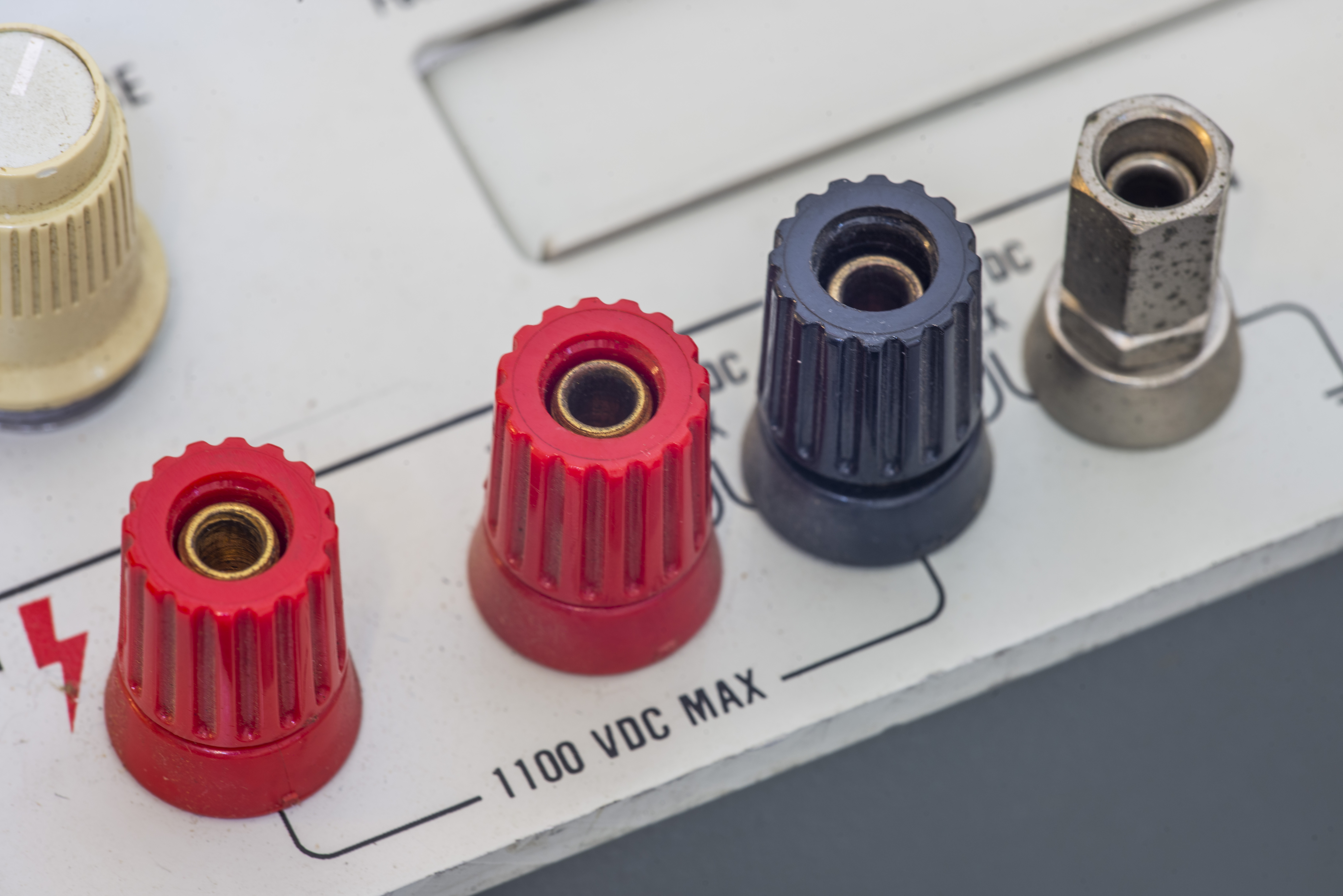
Image 4-6: Close-up on exterior controls and ports
Of course, reason of why this article is published in repair section very simple. This instrument is…
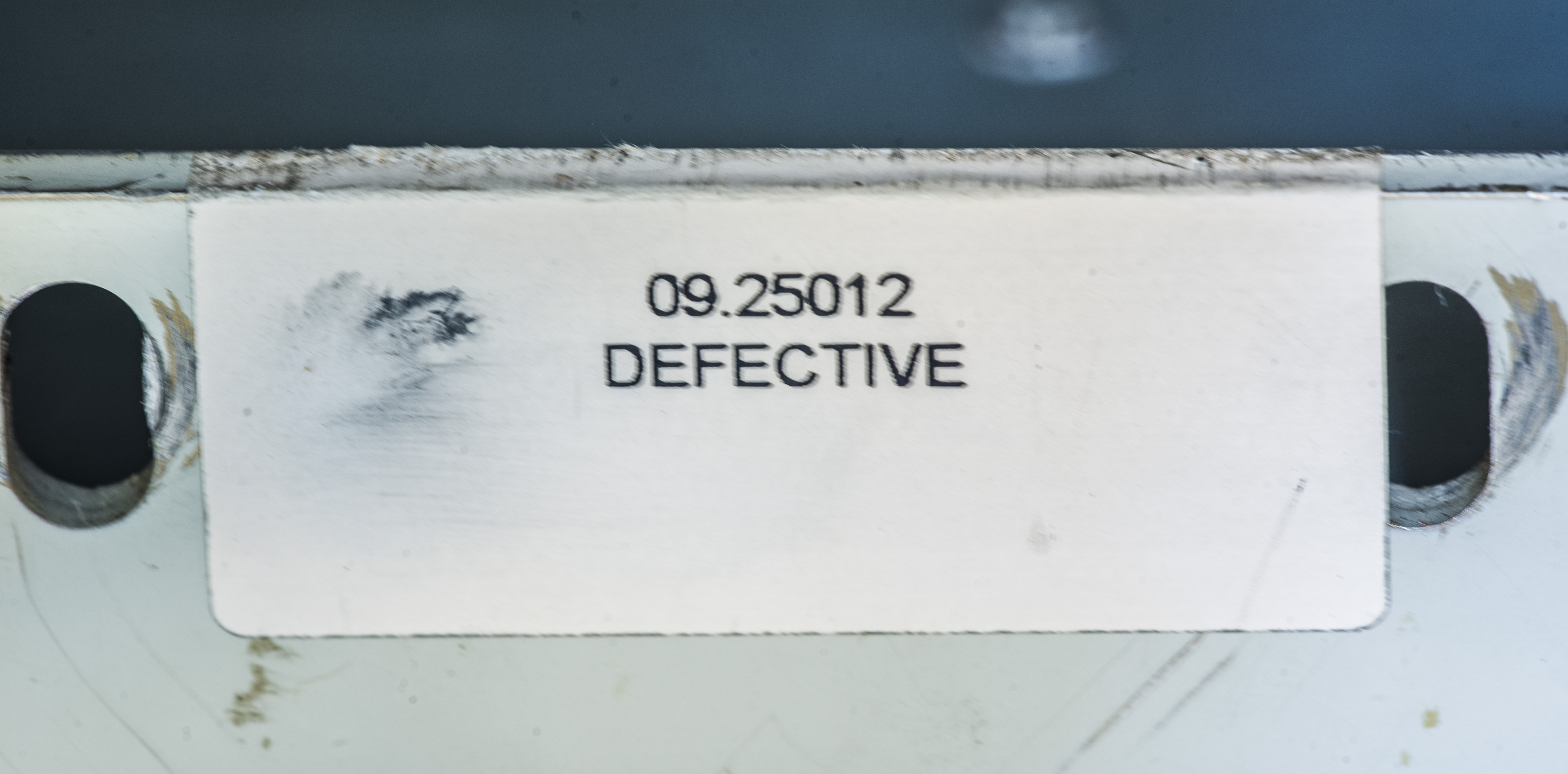
Image 7: Sticker on the unit
Diagnostics and visual inspection
- Few missing screws on top cover
- One screw was rattling inside the case
- Bit dirty outside
Here’s quick resistance measurements on output terminals, checked by Agilent 34970A in 2W mode.
| Decade A | Decade B | Decade C | Decade D | Decade E | Decade F | Decade G | |
|---|---|---|---|---|---|---|---|
| None | N/A | N/A | N/A | N/A | N/A | N/A | N/A |
| 0 | 0 | 0 | 0 | 0 | 0 | 0 | |
| 1 | 10000.43 | 8426 | 3697 | 936.8 | 909.3 | 909.2 | 909.15 |
| 2 | 20000.82 | 15994.4 | 6771.9 | 1747.7 | 1636.3 | 1636.3 | 1636.5 |
| 3 | 30001.34 | 217041 | 9224.3 | 2432.5 | 2184.2 | 2181.7 | 2182 |
| 4 | 40001.82 | 25538.7 | 11054.5 | 2991.3 | 2549.7 | 2545.4 | 2545.6 |
| 5 | 50002.2 | 27498.2 | 12262.2 | 3423.9 | 2734 | 2727.2 | 2727.5 |
| 6 | 60002.71 | 27582.5 | 12847.6 | 3730.6 | 2737.1 | 2727.2 | 2727.5 |
| 7 | 70003.08 | 25791.7 | 12810.5 | 3911.2 | 2558.9 | 2545.5 | 2545.6 |
| 8 | 80003.6 | 22125.9 | 12151.3 | 3965.7 | 2199.4 | 2181.9 | 2181.9 |
| 9 | 90004.05 | 16584.7 | 10869.7 | 3784.6 | 1658.8 | 1636.5 | 1636.4 |
| X/CAL | 107316.1 | 16868.3 | 11207.84 | N/A | N/A | N/A | 909.09 |
| CAL (A) | 107350.9 |
Table 2: Fluke 720A KVD ROUTPUT check, Ω
Measurement on input terminals does not give correct 100 kΩ or 110 kΩ so this mean resistance network of divider is broken somewhere. Wiggle and switching function switch and/or decade A switch sometimes gets to some reading like 98 or 96 or 107 kΩ, but next step brings resistance back to >1GΩ
Switch issue? Broken wiring? Blown resistor? Will find out.
EEVBlog member Jay_Diddy_B tested his unadjusted 720A, and his resistance measurements are as expected:
- From the 1.1 input terminal to Lo the resistance is 110.00 kΩ with dials set to 1.00000000
- From the 1.0 input to the Lo the resistance is 99.99952 kΩ, with the dials set 0.9999999
- The 1.0 input with the dials set to 1.0000000 is not a valid operating condition but mine measures about 107.5 kΩ
- The output resistance that I measured on the first three decades are very similar to yours.
Teardown
So now as we confirmed my unit is broken, time to remove covers and see what is inside.
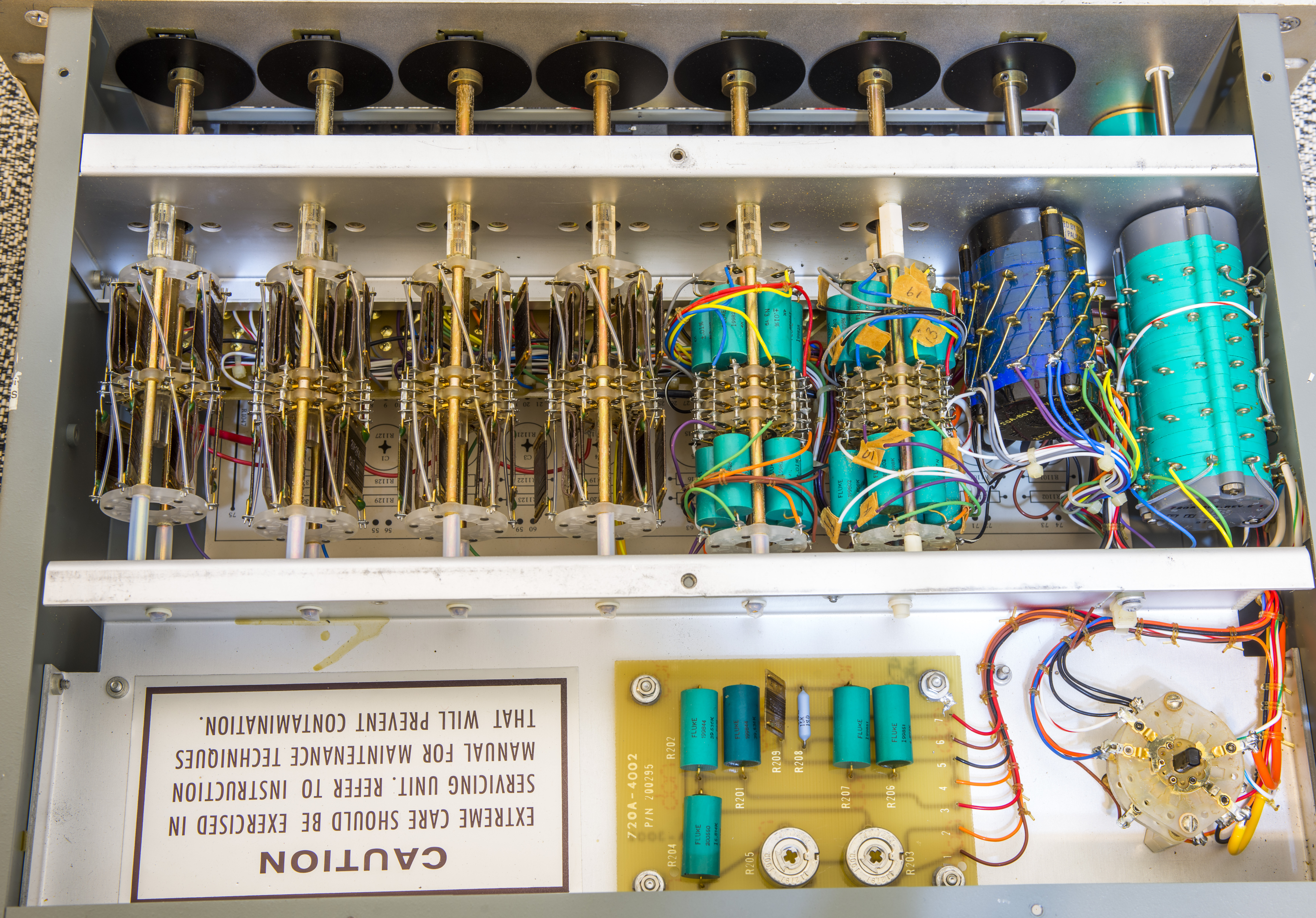
Image 8: Inside from top side
CAUTIONs labels with big bold words everywhere. Keep children and cats away during 720A service, with no pun intended.
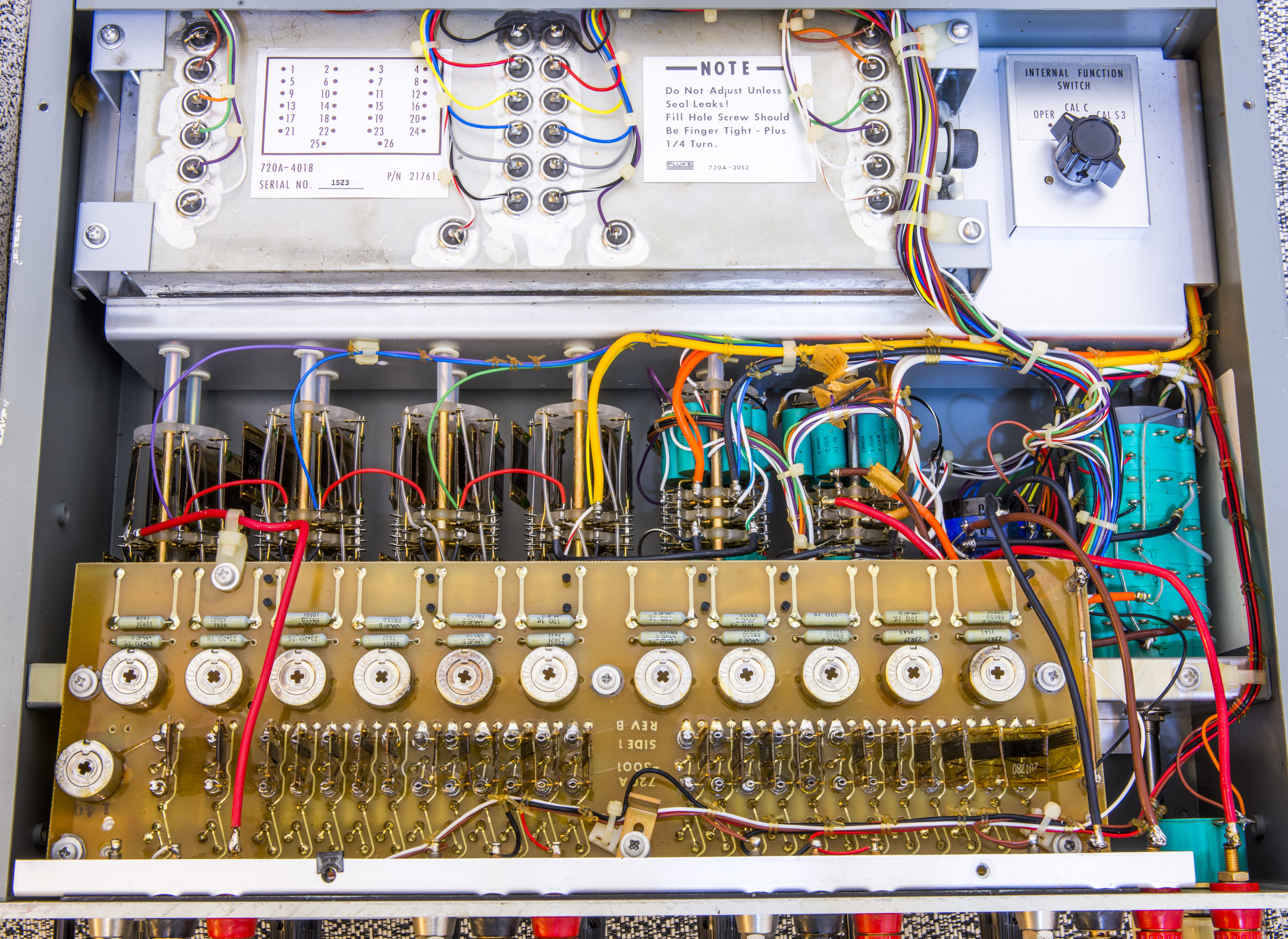
Image 9: Inside bottom side
Bottom side reveals some serious touch on details, with oil-filled resistor chamber for most critical first decade A. All components in our box are in place, nothing stolen or missing. Maybe except screw or two… Internal switch for calibration for third decade. It was set to OPER function as received.

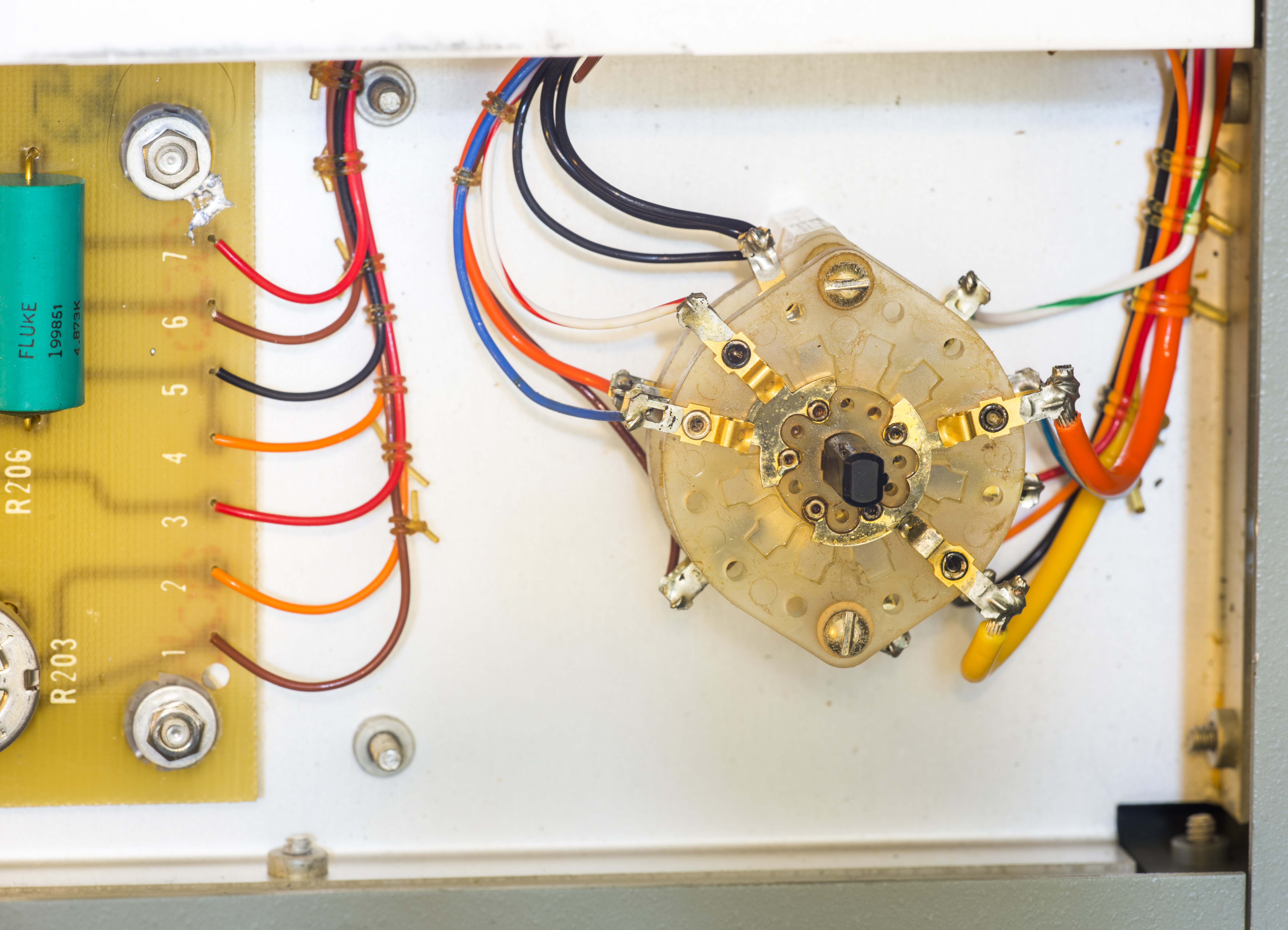
Image 10-11: Internal calibration switch
Little board with beautiful Fluke-made teal resistors mounted just above the oil tank from the top side.
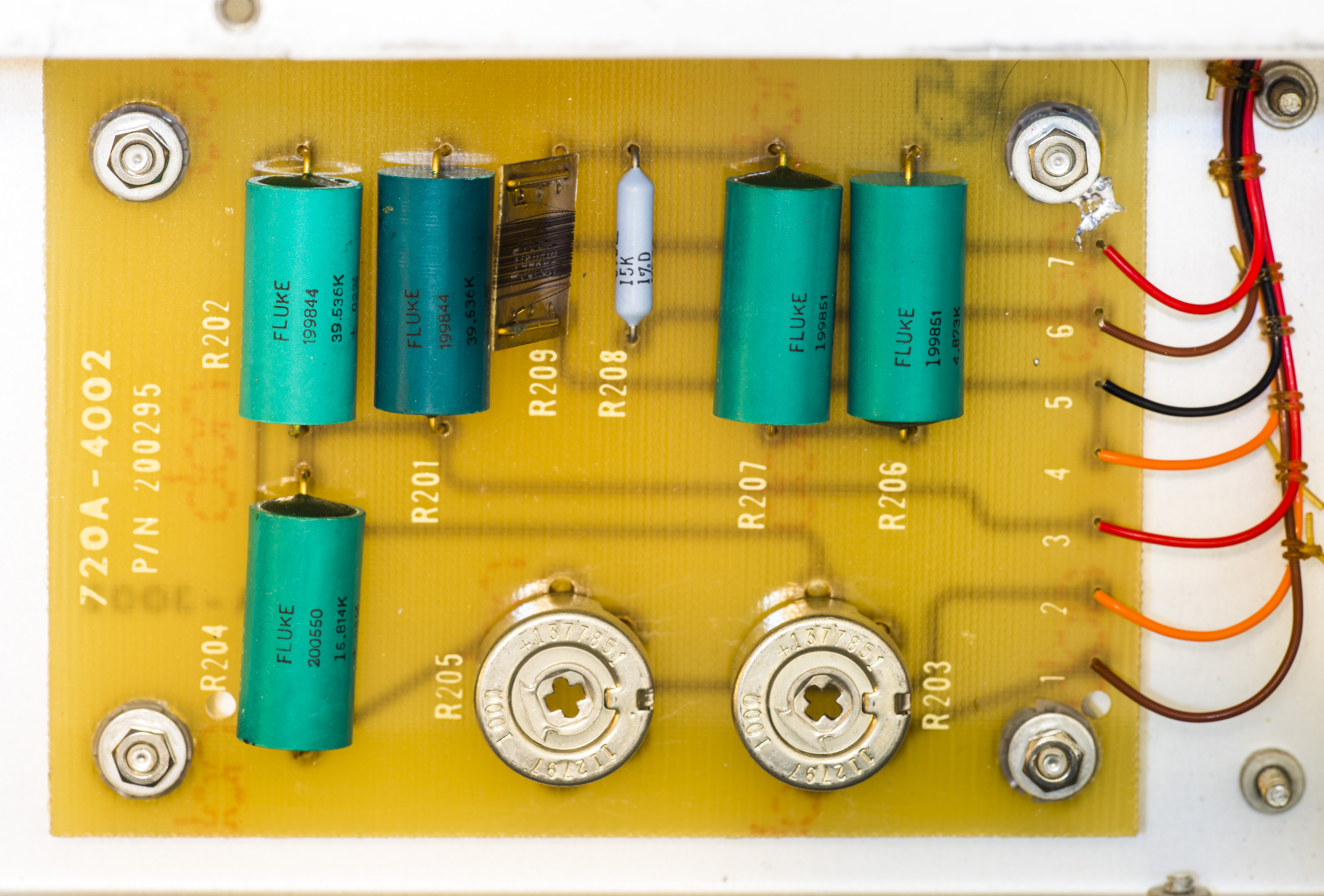
Image 12: Auxilary PCBA with precision WW resistors
Someone did peek inside before and left a solder blob near mounting screw?
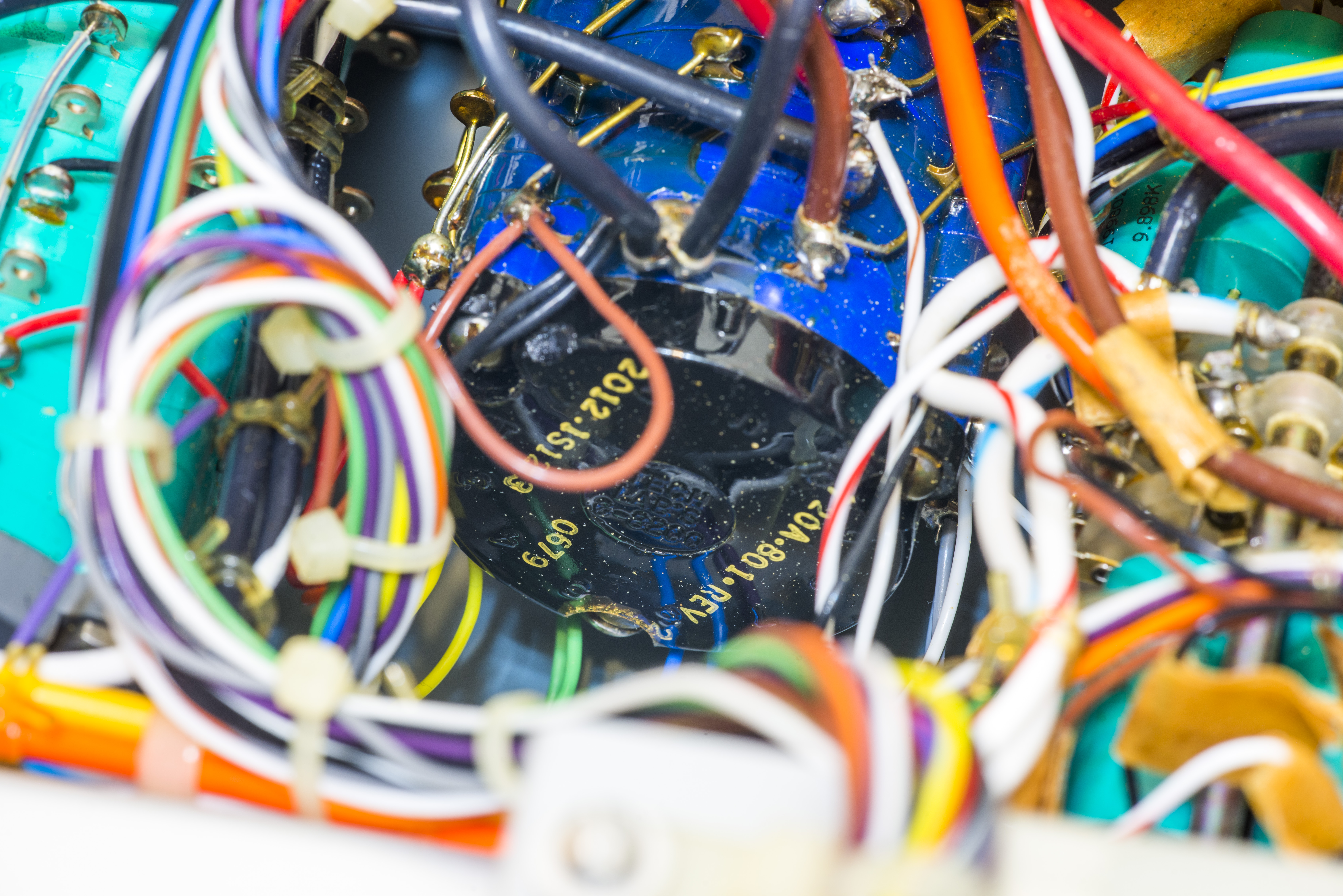
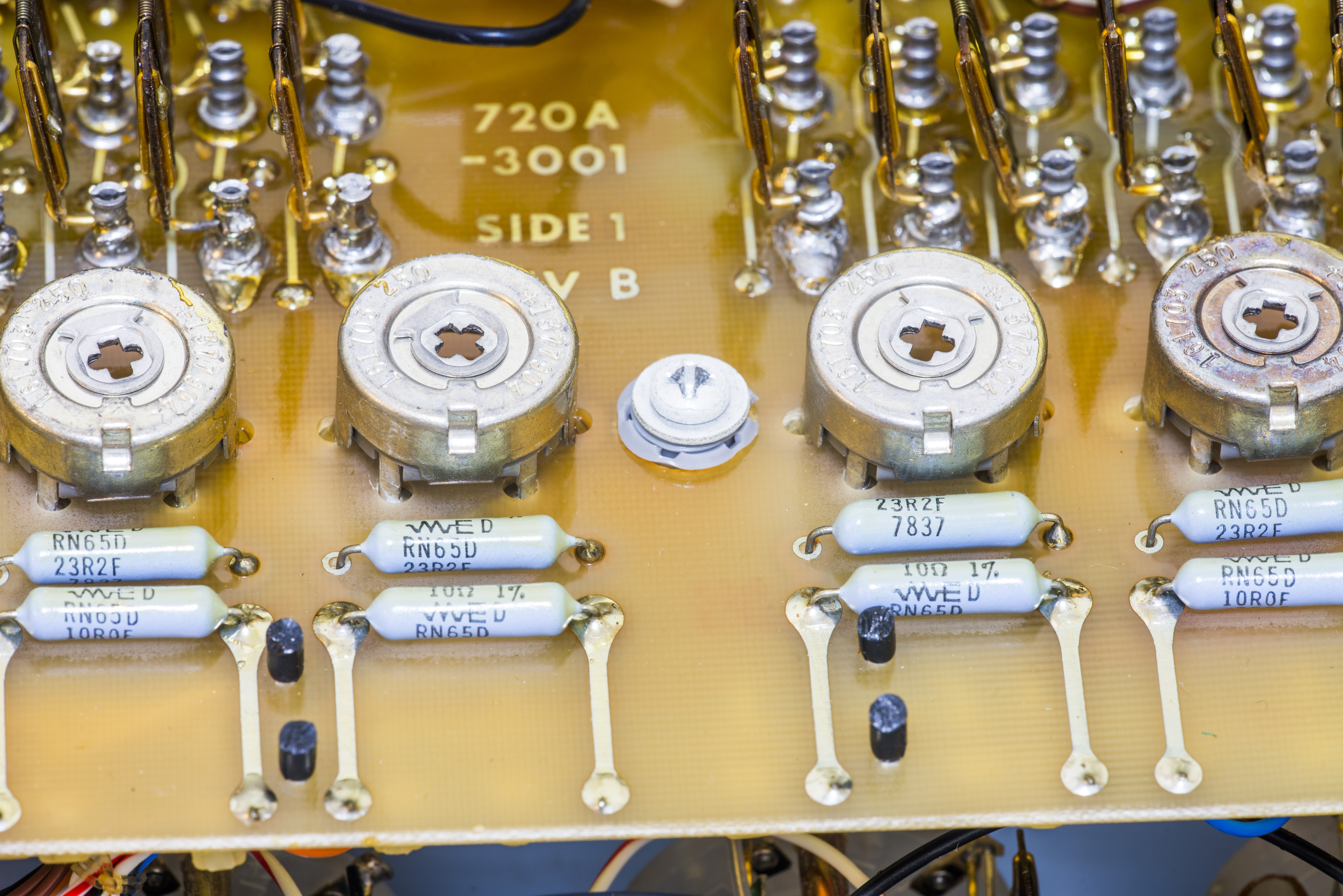
Image 13-14: Markings on rotary switch and resistors
If reading correct, date-code on on decade A switch is 6th week 1979, and resistors on 720A-3001 trimmer board are 37th week 1978. That reveals 40 year age of this instrument.
Function switch have many long rotary sections.
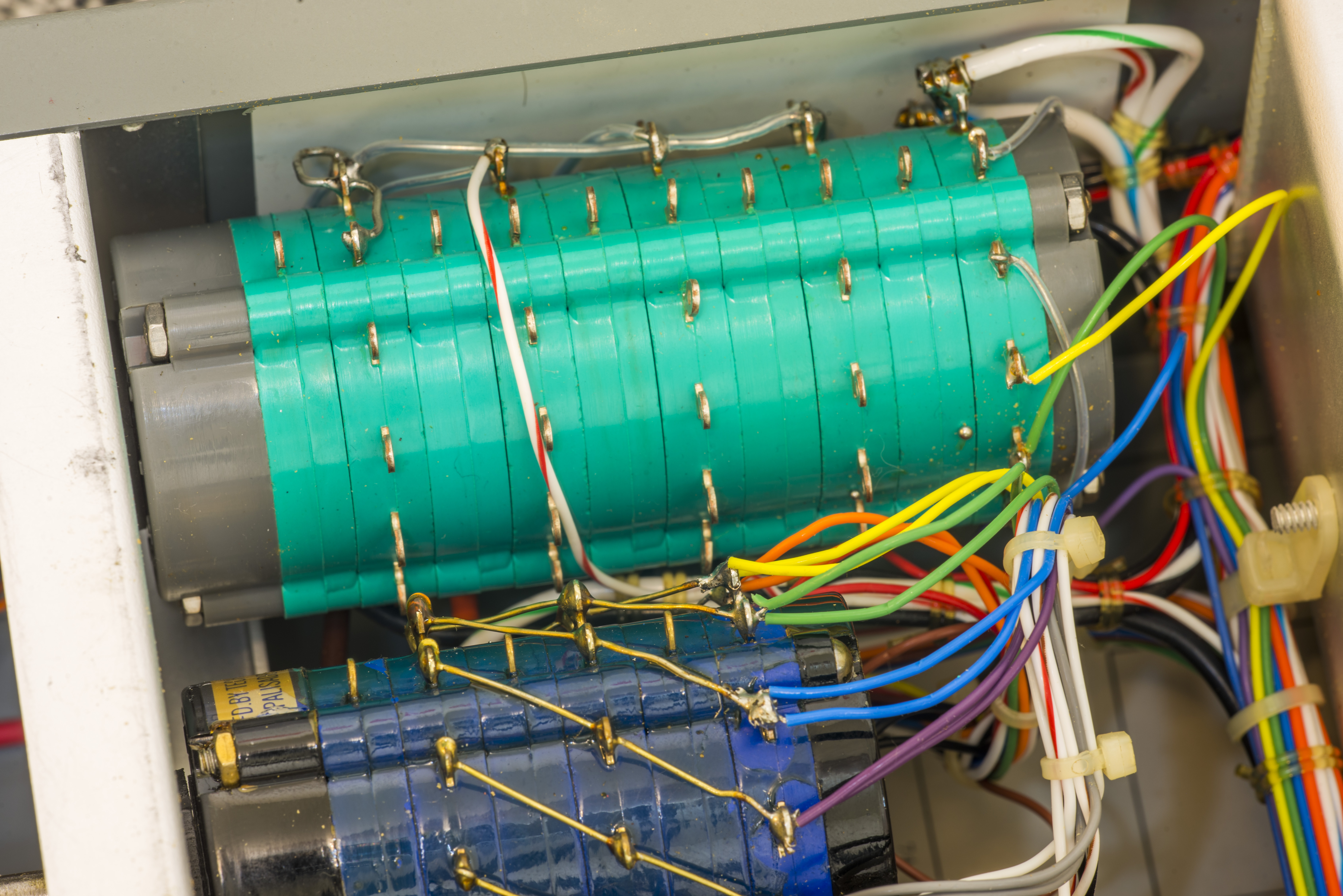

Image 15-16: Function switch
Take a look on decades more closely. A,B,C:
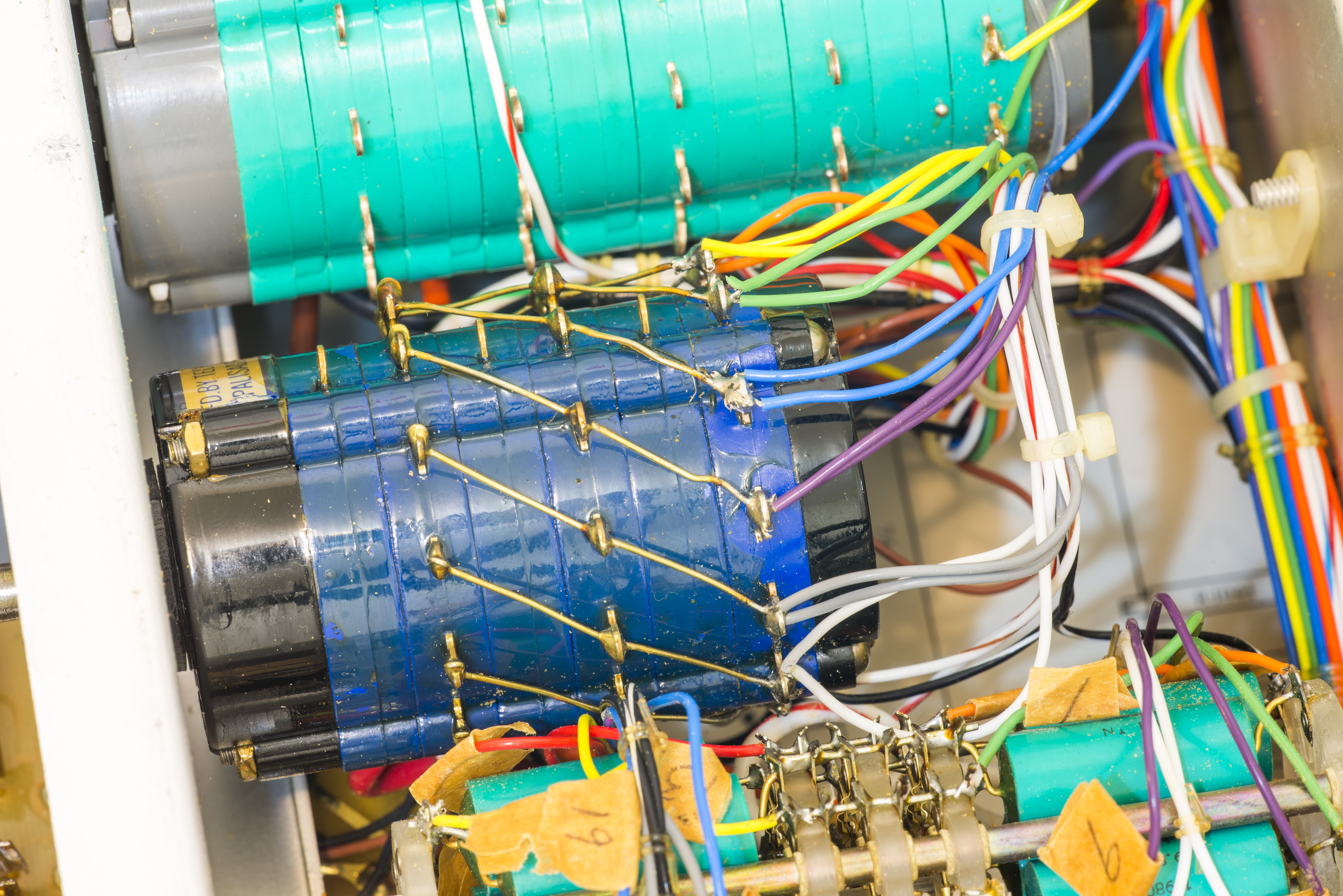
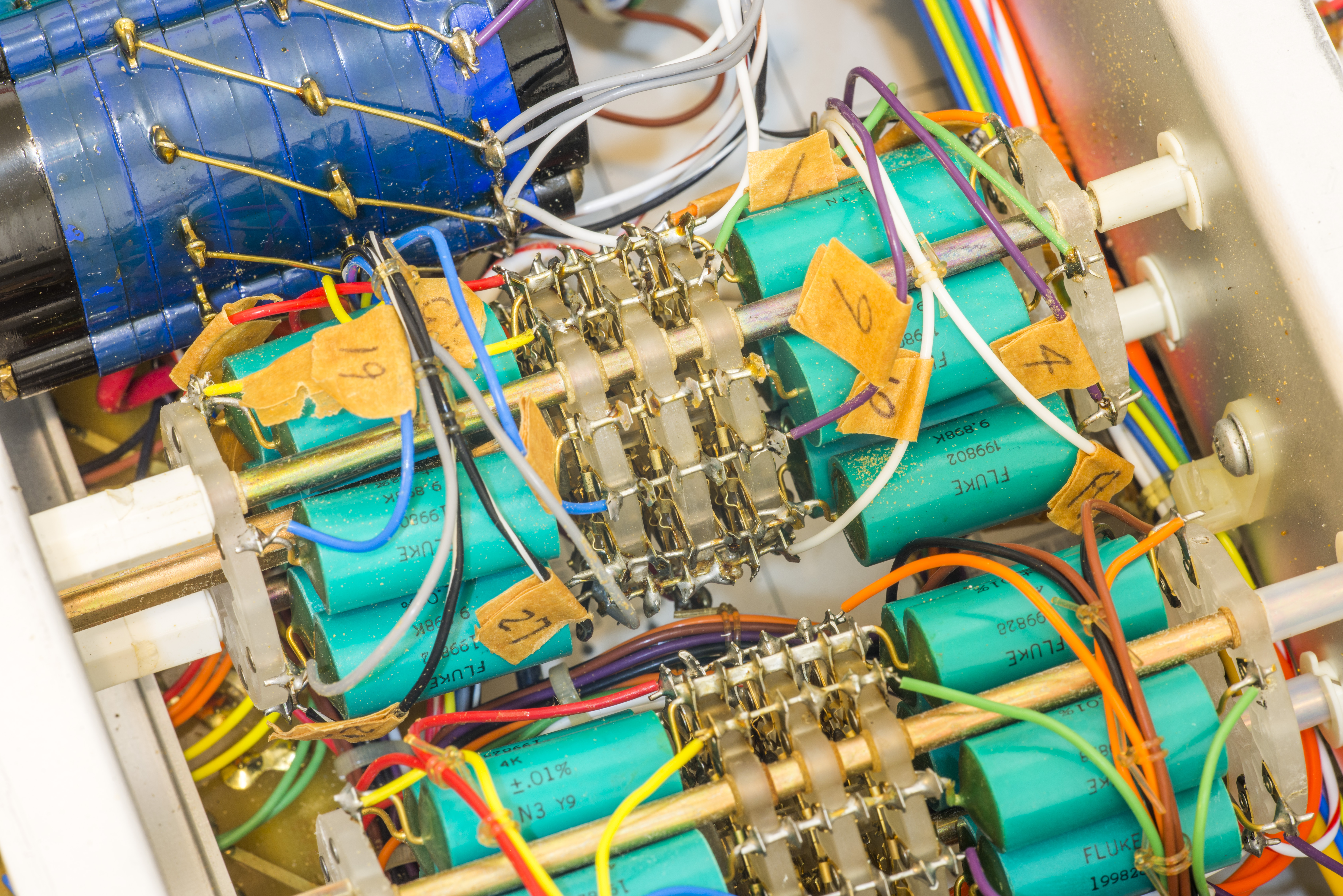
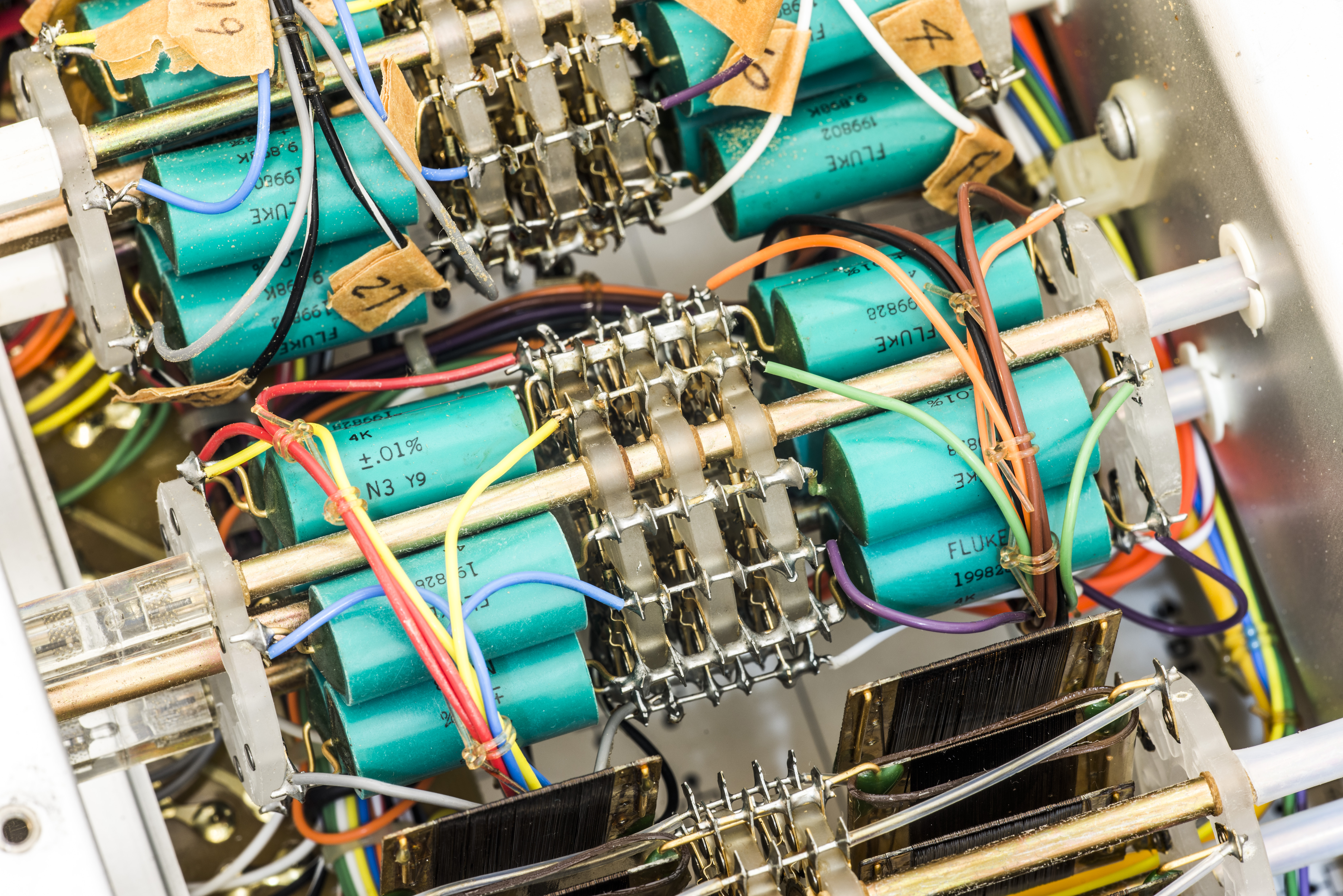
Image 17-19: Decades A,B,C
And D,E,F,G decades, which using same 1KΩ resistor and shunt resistor, forming KVD scheme.
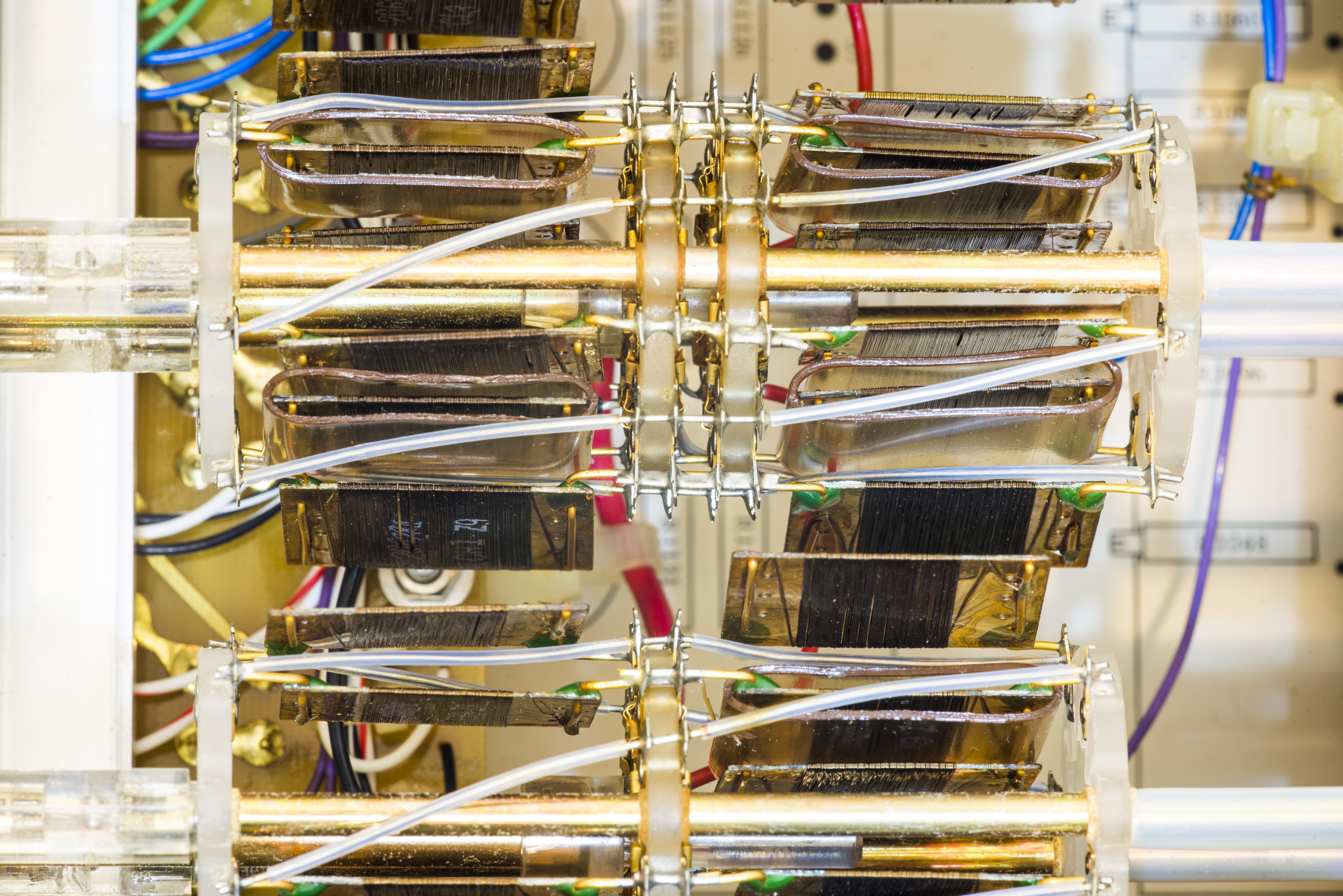
Image 20: Smaller 4 decades
More detailed photos of Fluke 720A’s resistors and decades used were revealed before, in previous article. Take a look on those, it’s worth to see.
Interesting to note, that newer 720A, such as one shown on bbs.38hot.net forums using teal epoxied resistors for decades D and E as well. Also PCBs are more usual modern green mask type there.

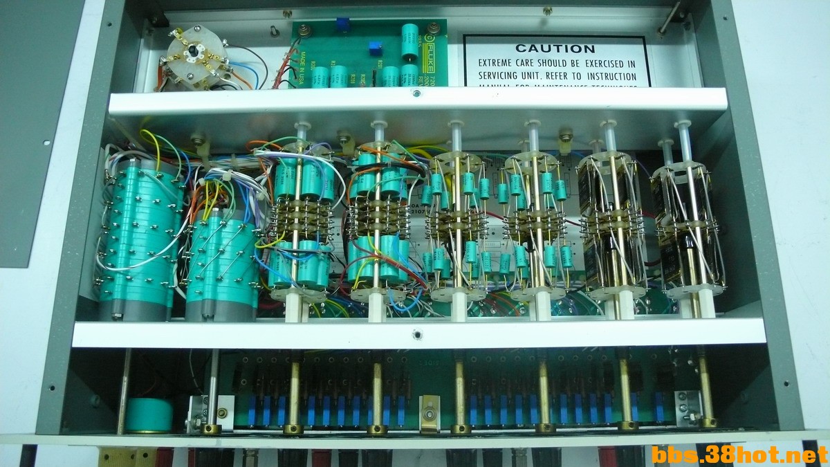
%(imgref)Images courtesy bbs.38hot.net
Bottom PCB have long array of low-resistance wire-wound resistors, few variable 1-turn potentiometers and multi-turn trimpots. Later ones are accessible from front panel to implement calibration functionality for decades A and B.
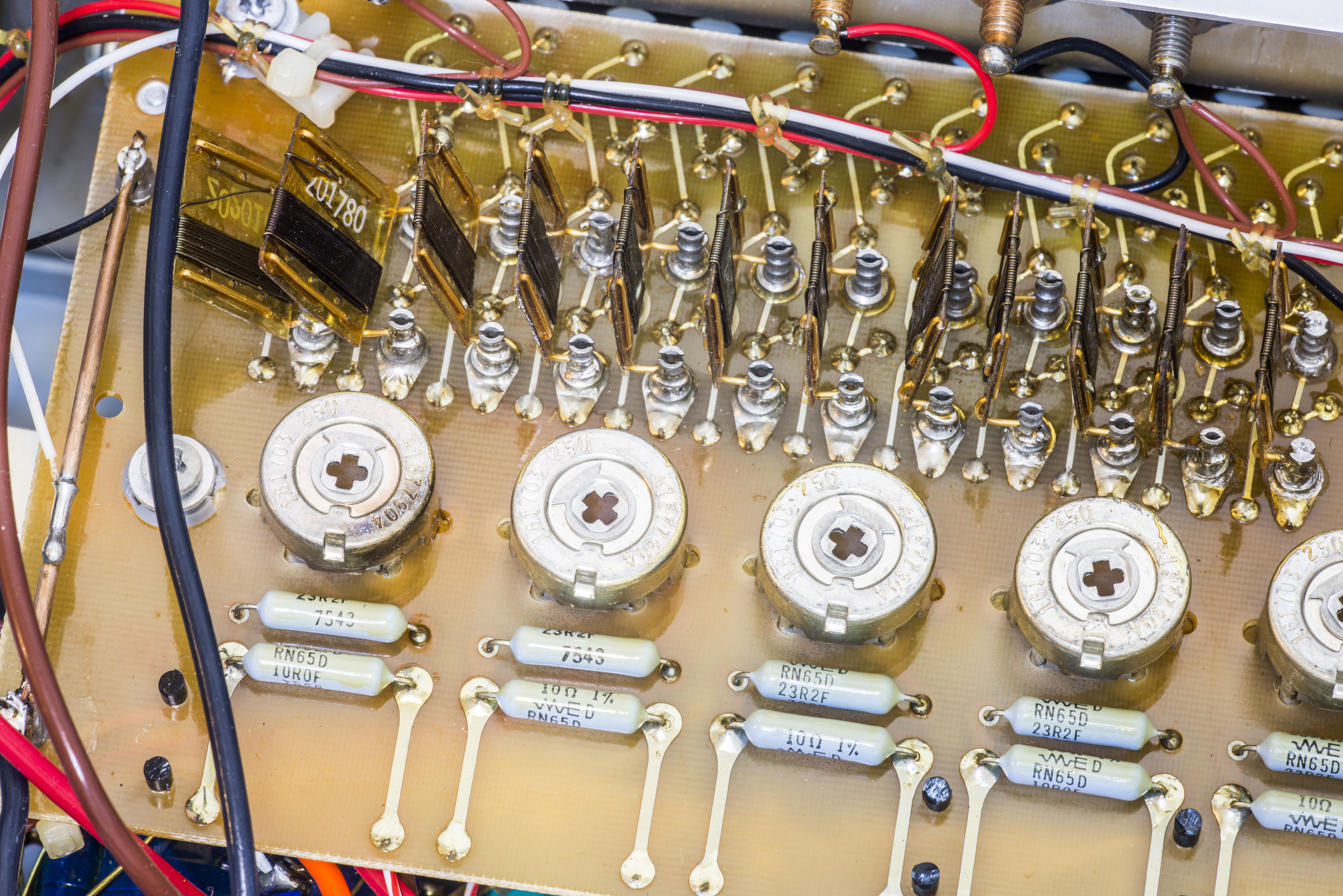
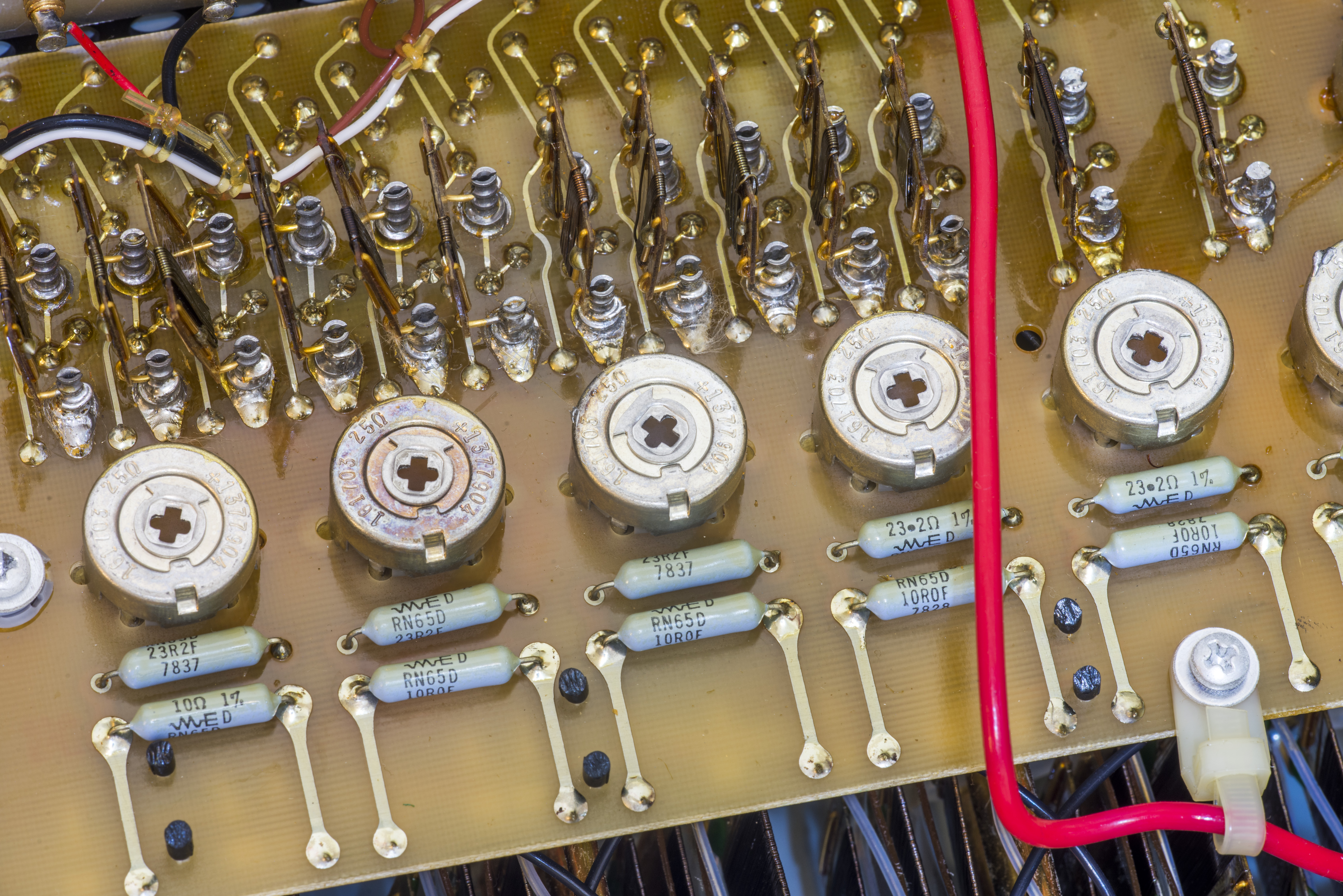
Image 21-22: Trim PCB assembly
Also connection to input and output binding posts has got my attention, as soldering does not look very good. Perhaps previous failed repair attempt by owner? That could bring bad news, as it’s almost always better not to deal with badly repaired/serviced equipment. The single turn pots are wire wound, manufactured by CTS.

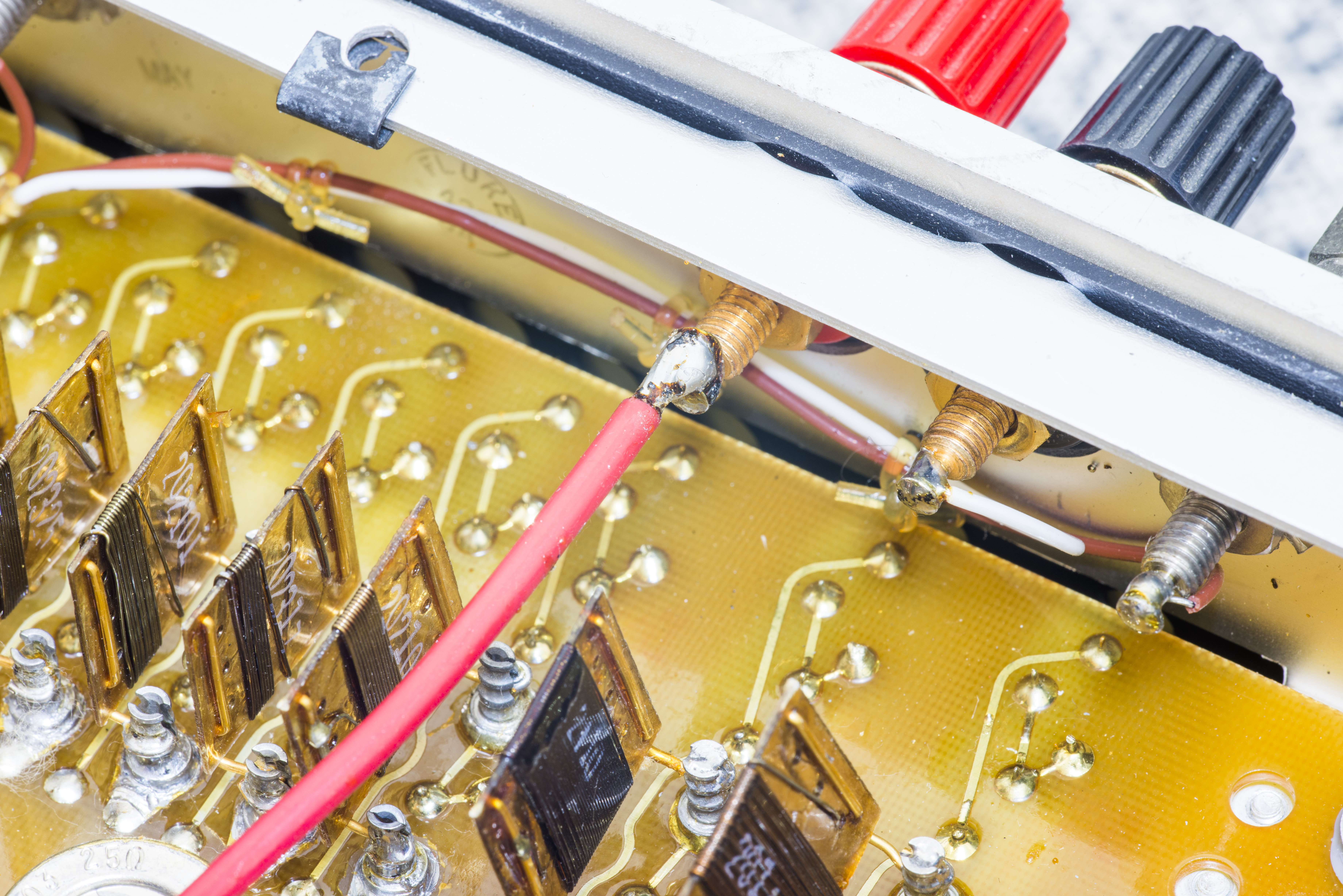
Image 23-24: Front panel binding posts soldering job
Let’s see more oil-filled chamber, which have resistors of decade A inside:
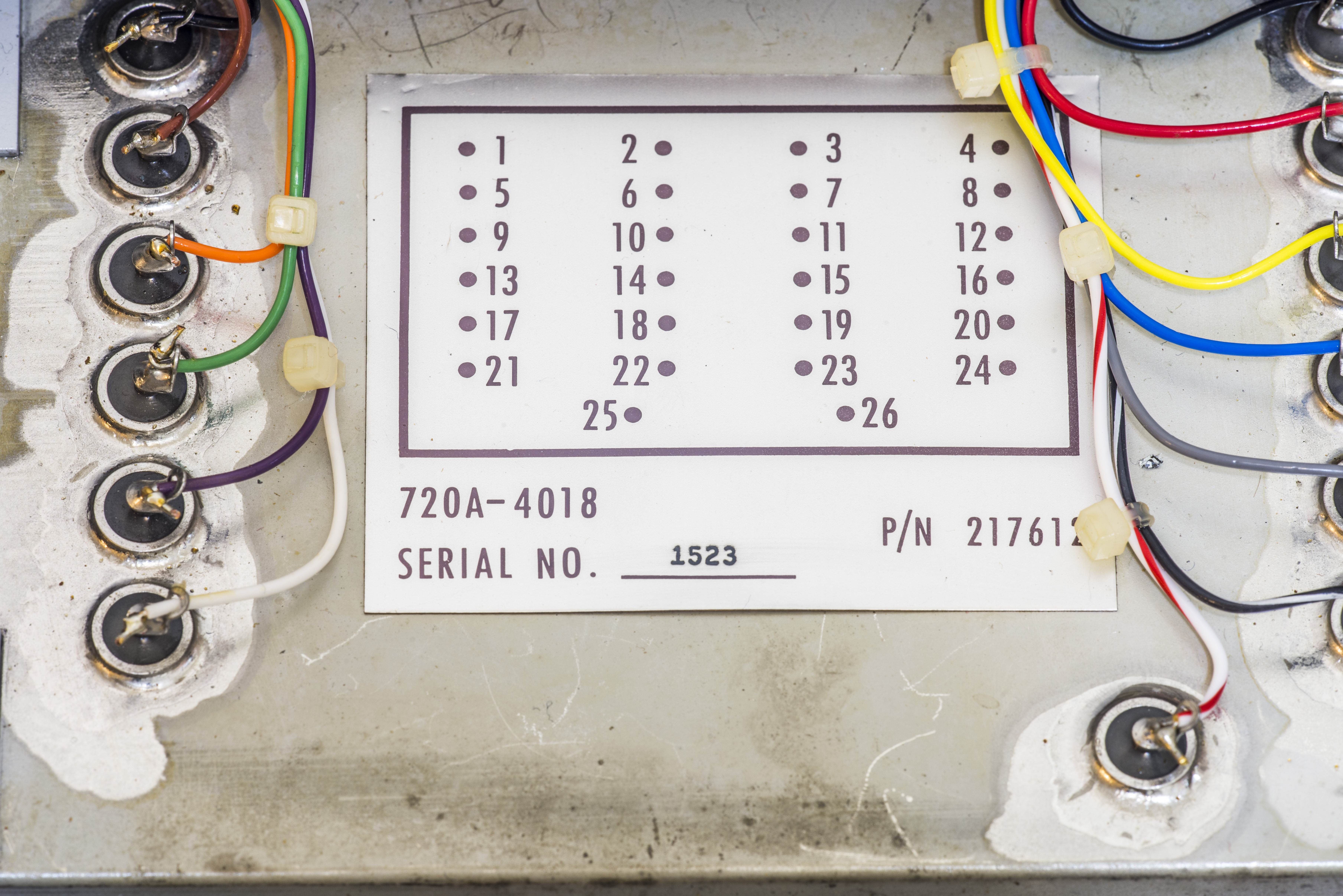
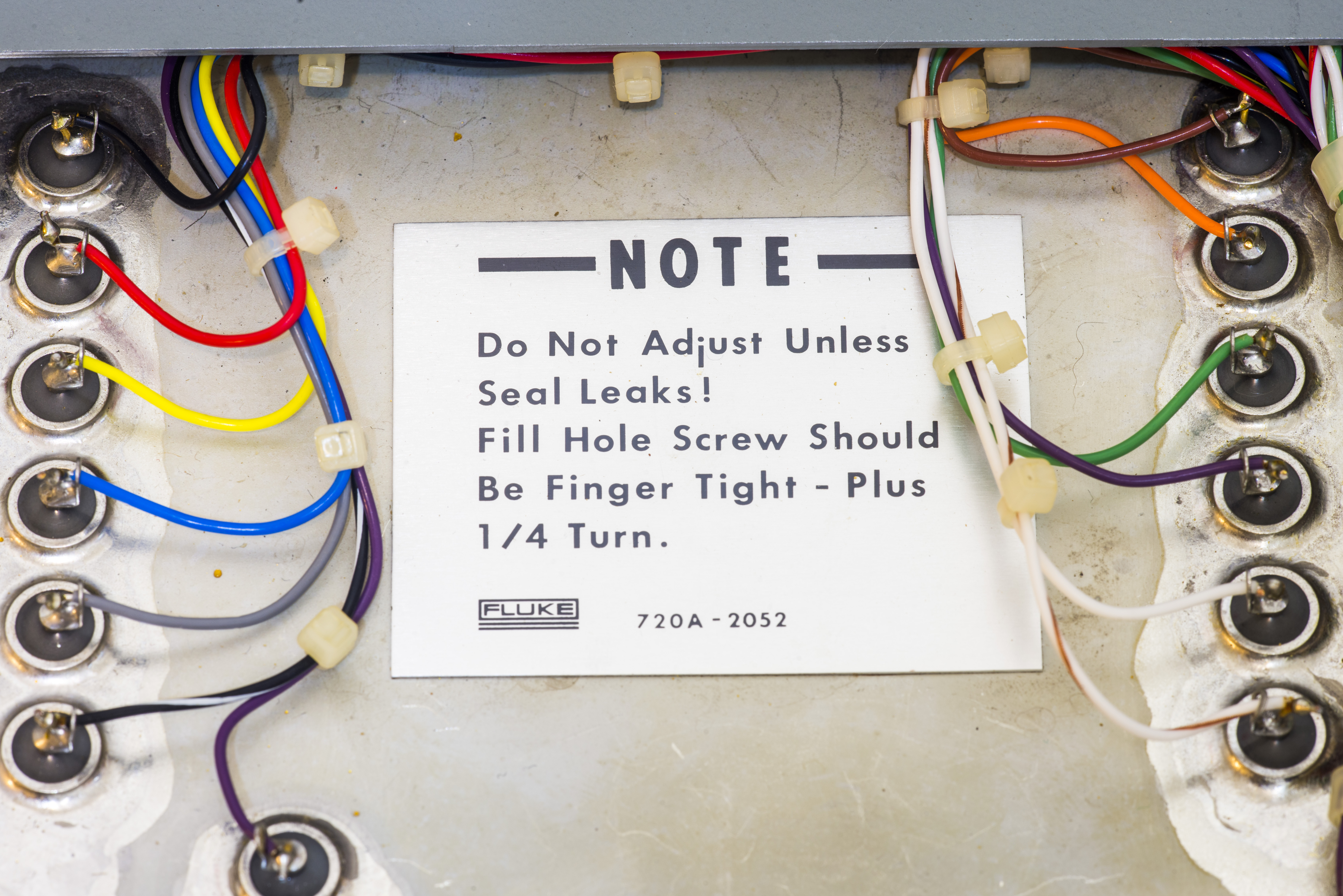
Image 25-26: Oil-filled main decade A
Hermetic pass-thru terminals, color coded wires, filling port. Isn’t it pure engineering joy?
There are no any active thermal regulation inside 720A, so Fluke engineers went other way around thermal stability and performance. On sub-ppm performance levels there are no insignificant details, so great care was taken to guarantee design targets.
Take a look on KVD conceptual schematics. It’s quickly become clear that most critical for KVD performance is first decade A, on which most of input voltage will drop during operation. Later decades only fine-tune resistance of primary resistors in decade A.
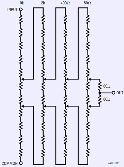
%(imgref)Image courtesy Linear Technologies Application Note 86 by Jim Williams, Jan 2001
In case of Fluke 720A resistors in main first decade are just about 10 KΩ in value, enclosed in hermetic oil-filled container. Trim and adjustable resistors are outside of oil container, as their performance requirements are not that important. Placing all resistors inside same oil-filled container does not make them more stable or precise, but instead equalize resistor temperatures even with different power dissipation of resistor network. Hence oil fill help to keep all resistors of decade same even with quick change in input voltage and dissipated power.
Of course it’s still very important to keep thermal coefficient of those resistors, and more importantly their curve deviation/temperature characteristics. This need to be as closly matched as possible, so overall resistor network performance and temperature coefficient stay below required 1 ppm/°C to achieve 0.1 ppm ratio linearity.
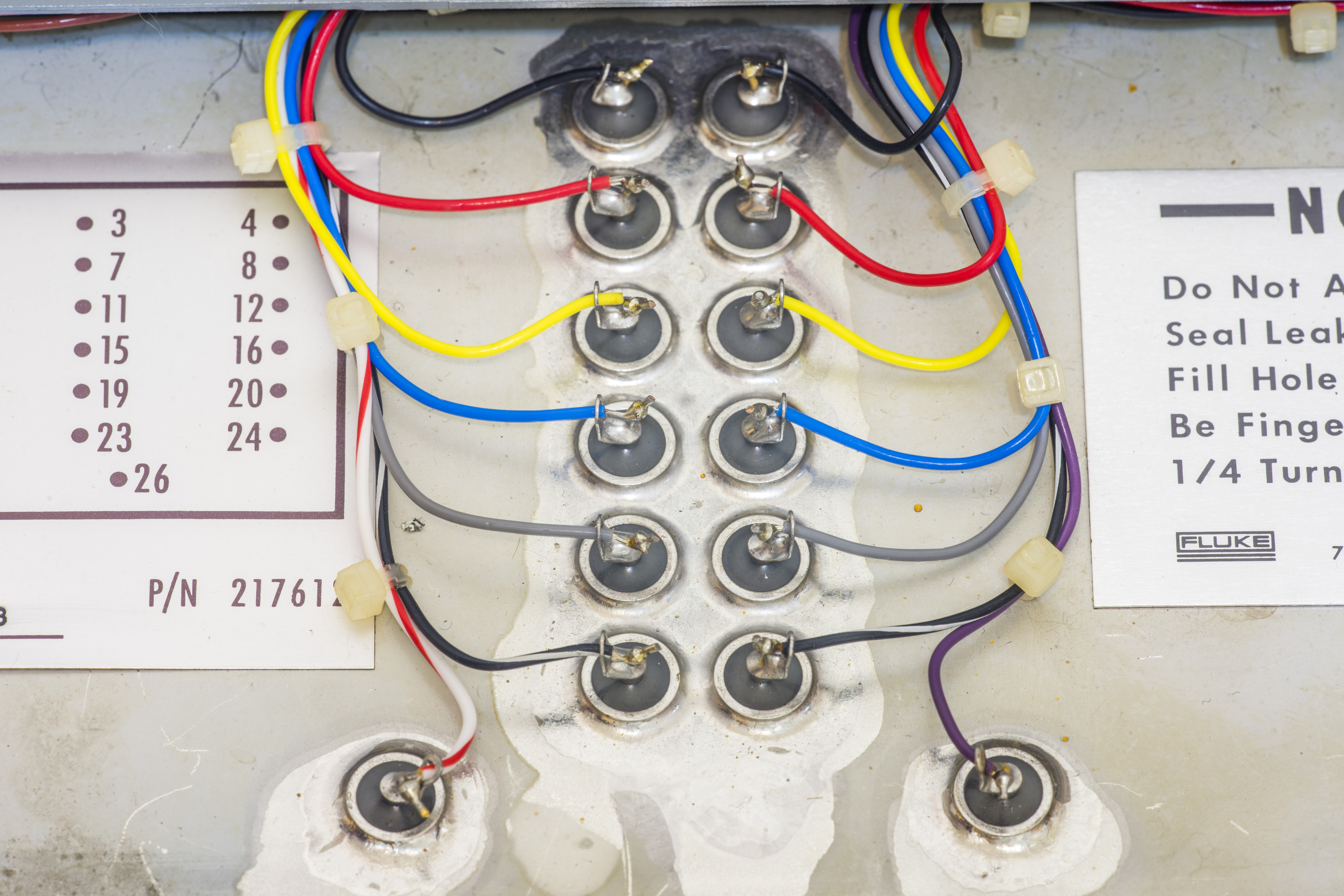
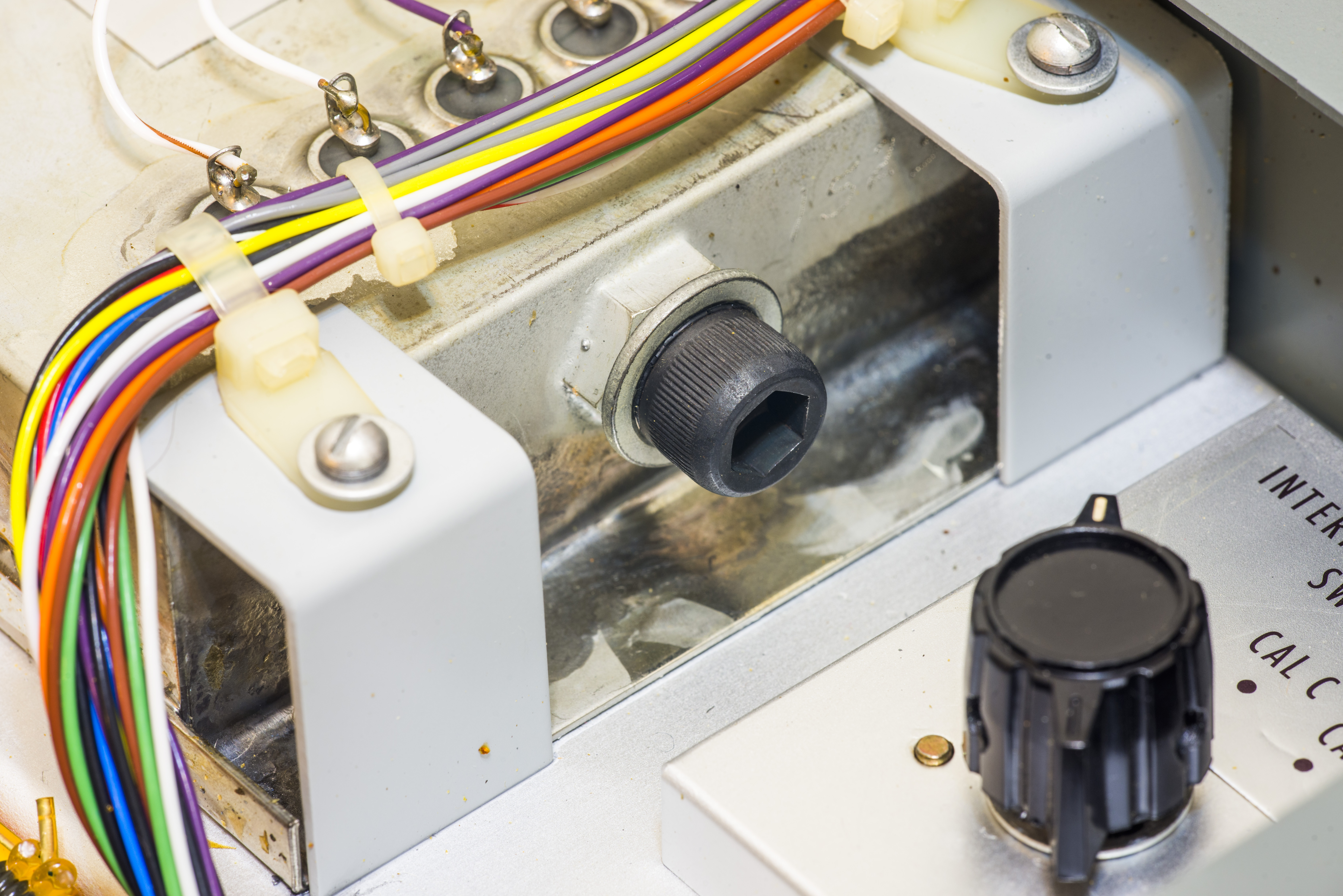
Image 27-28: Oil-filled main decade A fill port
Here comes first trap for young metrologists and precision nuts. Every specific resistor may have same low TCR on specific temperature, but it’s wrong to assume that TCR will be constant with temperature variation. On coarse precision levels it may be possible to use this constant linear TCR value, and add simple linear correction. Such correction is often called α-correction. Precision resistance standards often come with specified α and β coefficients.
Many of metrology grade instruments and equipment, such as Fluke 742A, 750A, 752A, 5450A use α-compensation scheme with linear TCR correction. On opposite case, β-correction is more complex non-linear one, rarely used due to difficulty of finding required matching in expensive resistor lots.
There is very small amount of oil residue on the box, but filling port is dry, so I’d assume for now that it was not open or tampered.
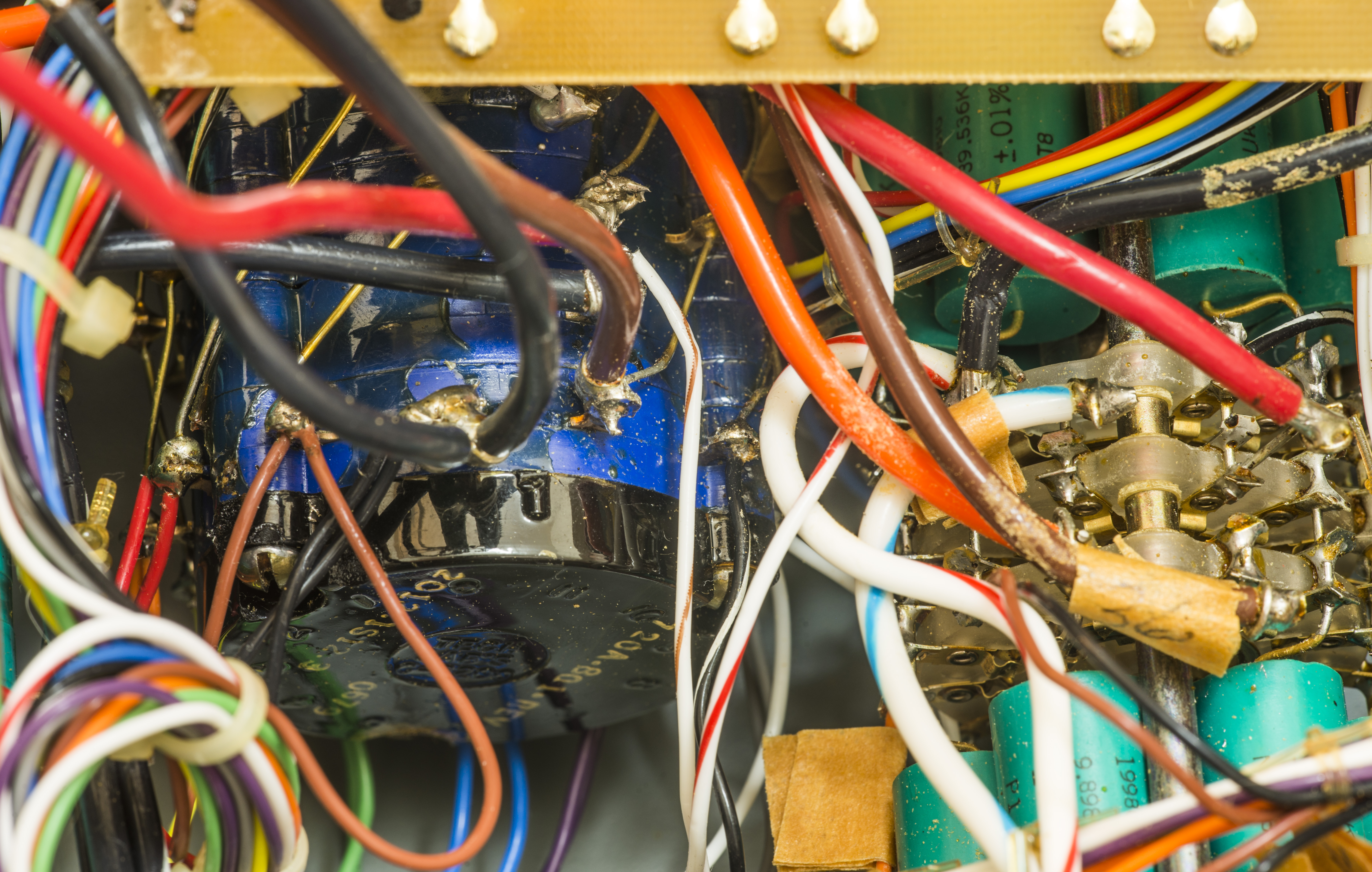
Few extra photos of wiring and routing around rotary decades.
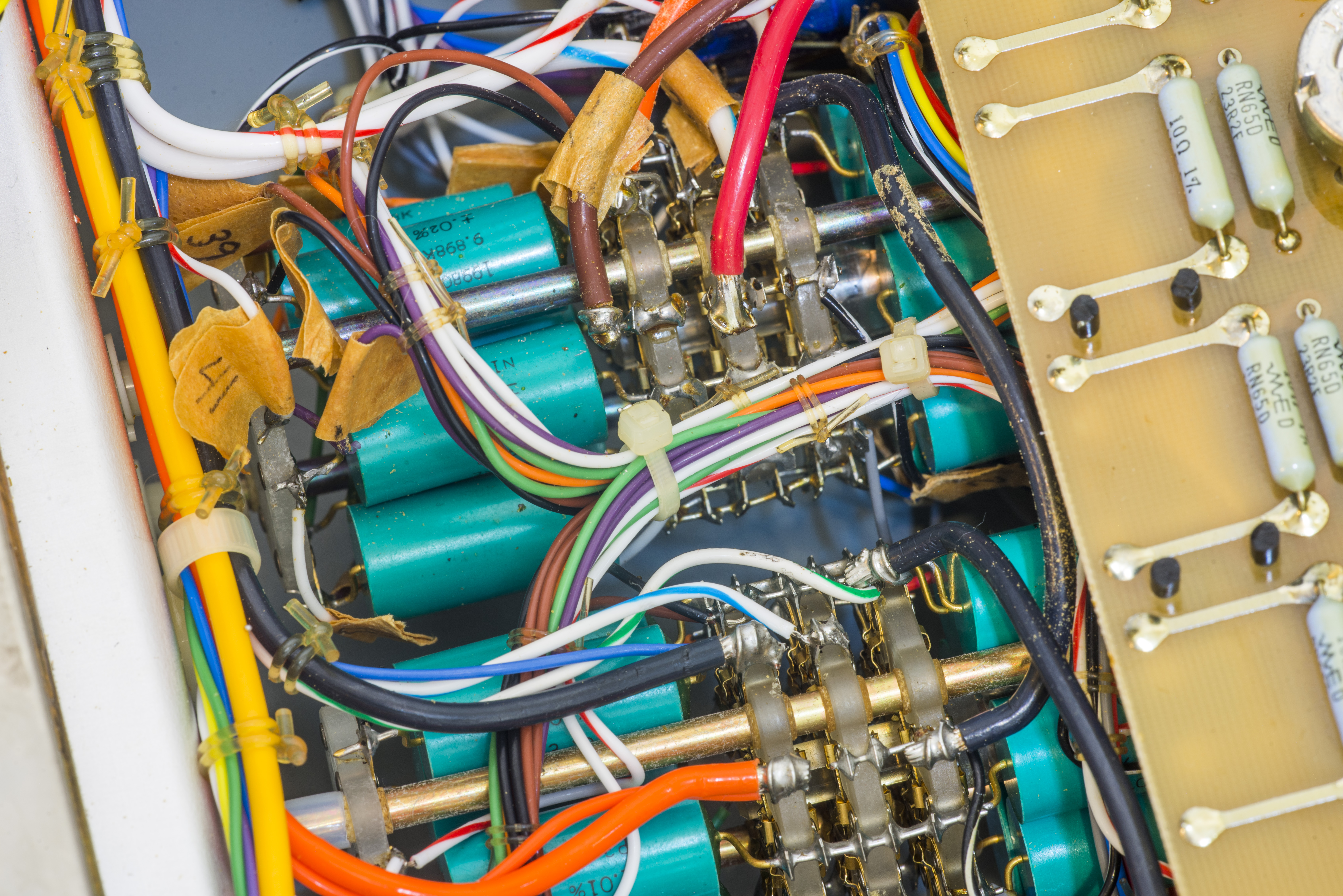
Image 29: Wiring around decade B

Image 30: Wiring harness, all fixed in place
There is also little 5K KVD-pot with co-axis fine and coarse adjustment for balancing bridge.
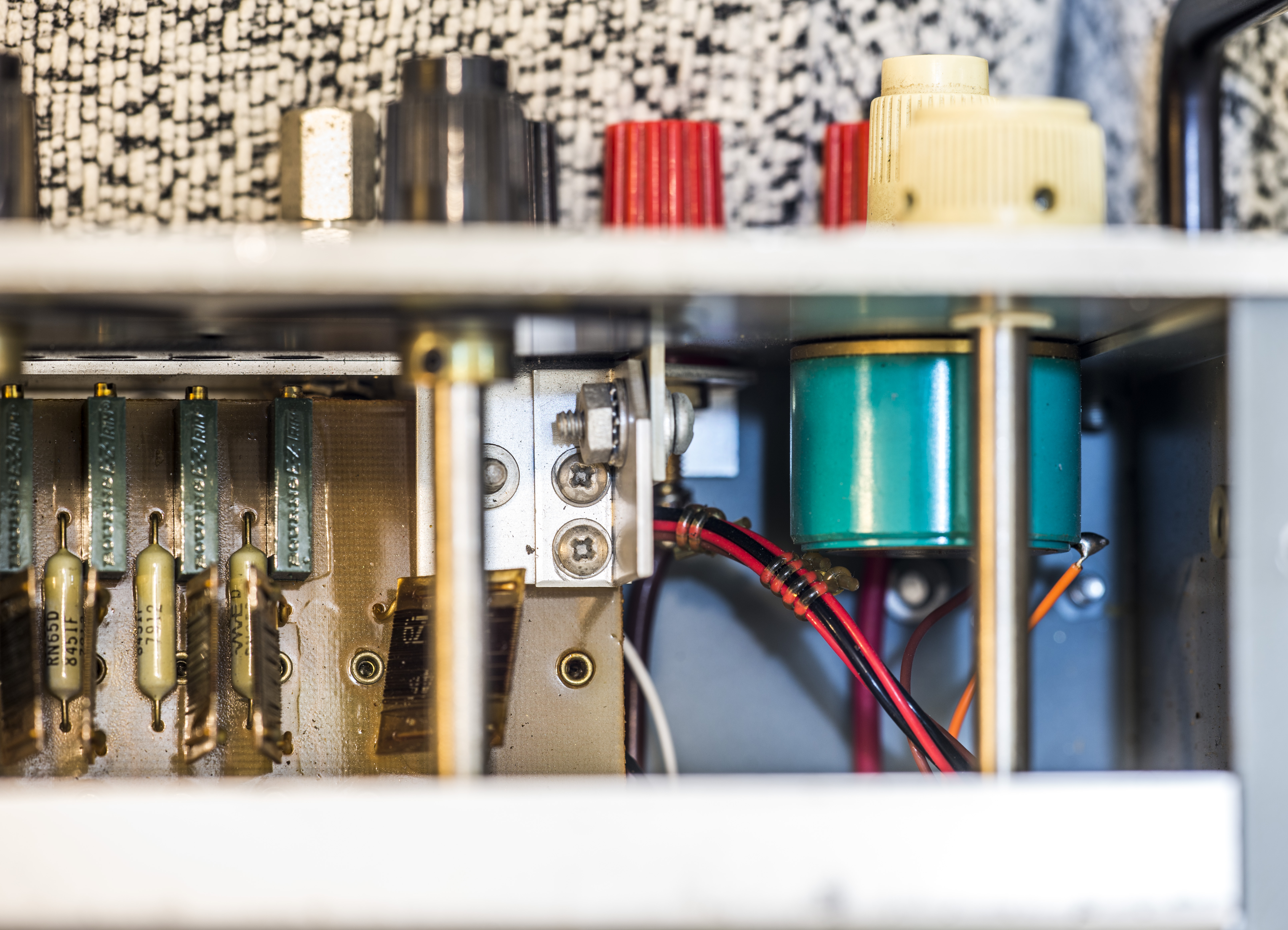
Image 31: Bridge balance pot and trimmers accessible from front panel
EEVBlog member lowimpedance mentioned some good details about L&N switch, which is very similar to one used for decade A in this Fluke 720A KVD. Specified capacitance <1.0 pF, voltage rating up to 1500 V and insulation resistance over 1012 Ω is pretty amazing by past or today standards.
Troubleshooting and repair
Incorrect wiring on Decade A switch
Continuity measurements revealed lack of connection from Input terminals to the beginning of Decade A resistor network.
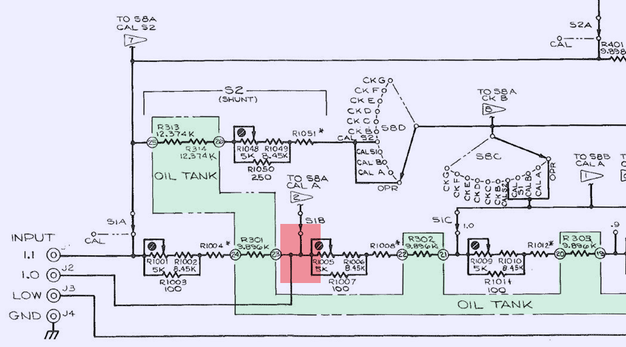
Image 32: Schematic section of Decade A network
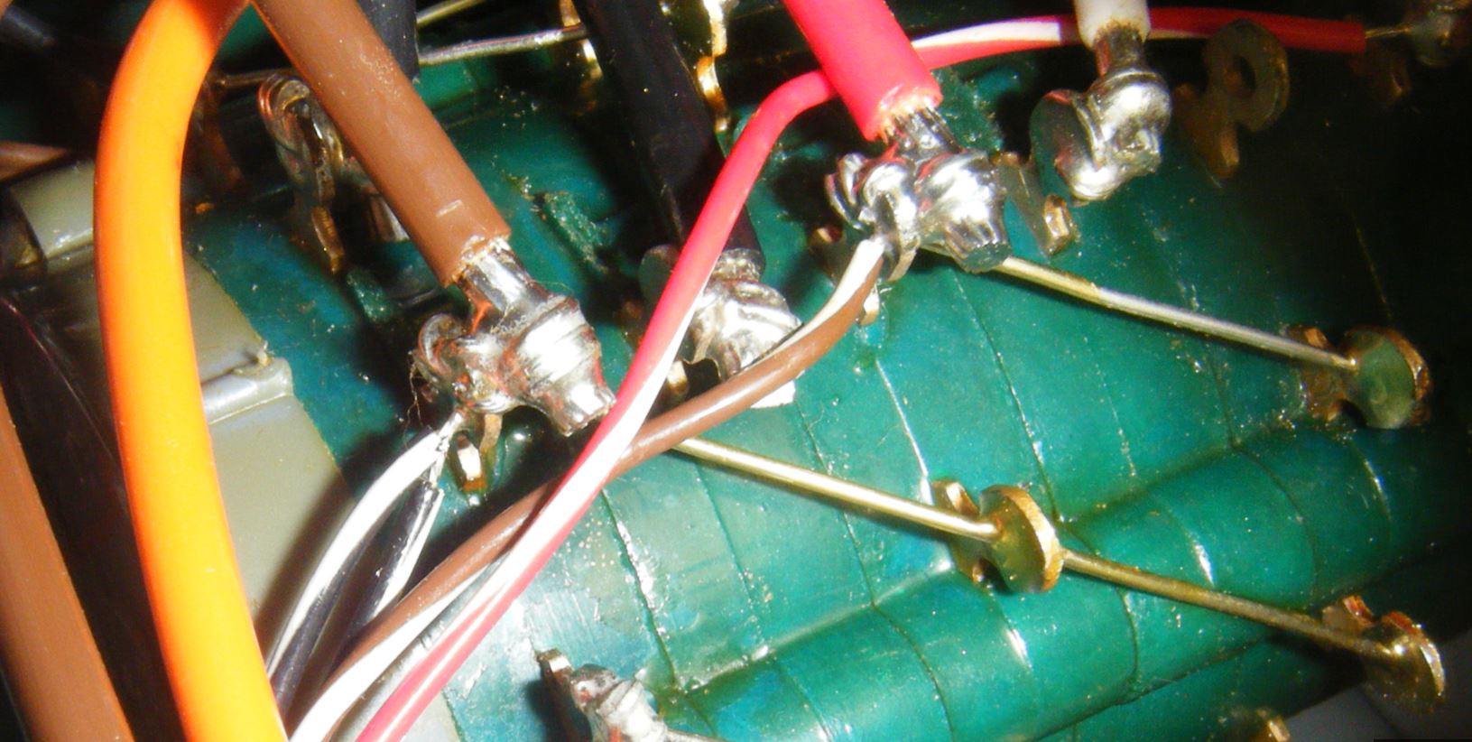
Per schematics marked red node should connect directly to INPUT 1.0 binding post. But instead we had no connection there:
 !
! 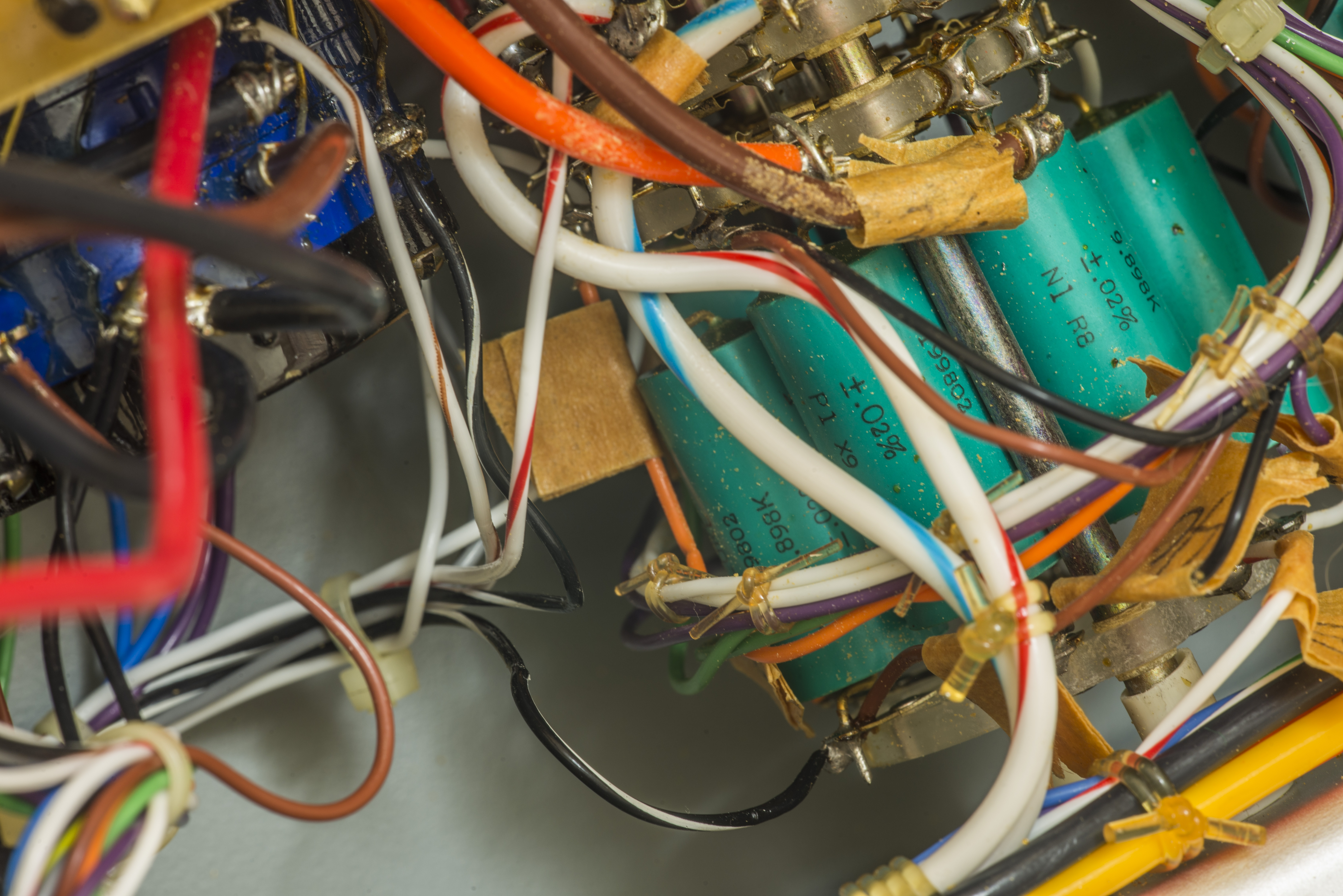
Image 33-34: Incorrect wiring on decade switch
Black/White colored wires should be connected to same point with thick brown wire from INPUT 1.0 terminal. One of those Black/White wires is coming from pin 23 of oil-tank resistor network assembly and second is going to trim PCBA with R1005. Resistors R1005, R1006 and R1007 are checked and well within expected range, so no problem there.
Here’s how correct wiring should look like.
%(imgref)Image 35: Correct wiring from good F720. Courtesy Jay_Diddy_B
Also if one to compare wiring photograph with good F720A, there is clearly visible difference:
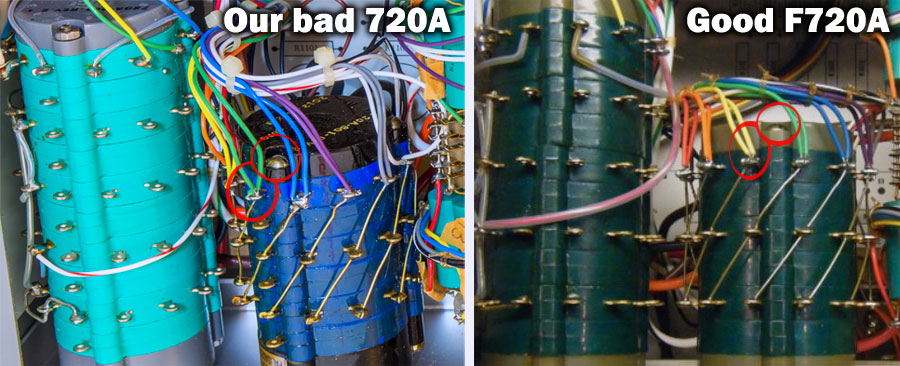
Image 36: Wiring error on decade A
This reveals that all decade A resistors are wired incorrectly by one position counter-clockwise from switch rear view.
Faulty Decade A switch
Well, our quest with Decade A does not end so quick with only bad wiring, as even after reassembly of wiring properly, divider does circuit does not work as expected. RINPUT 1.0 got to 80.000KΩ so we got right direction, but nor input or output resistance changes were observed, no matter which dials position was set. With ROUTPUT we got very fine 1:2 fixed divider, instead of KVD.
Check on all resistor pins from oil-filled “A” decade tank revealed that positions from .4 to .7 are shorted by 103 Ω, which is essentially trim resistance. Further check shown that three of Decade A switch positions are dead short (<0.05 Ω) on any dial position.
Since we had extra switch, bought half a year ago for parts, let’s take good switch hood off to confirm there should be no shorts:
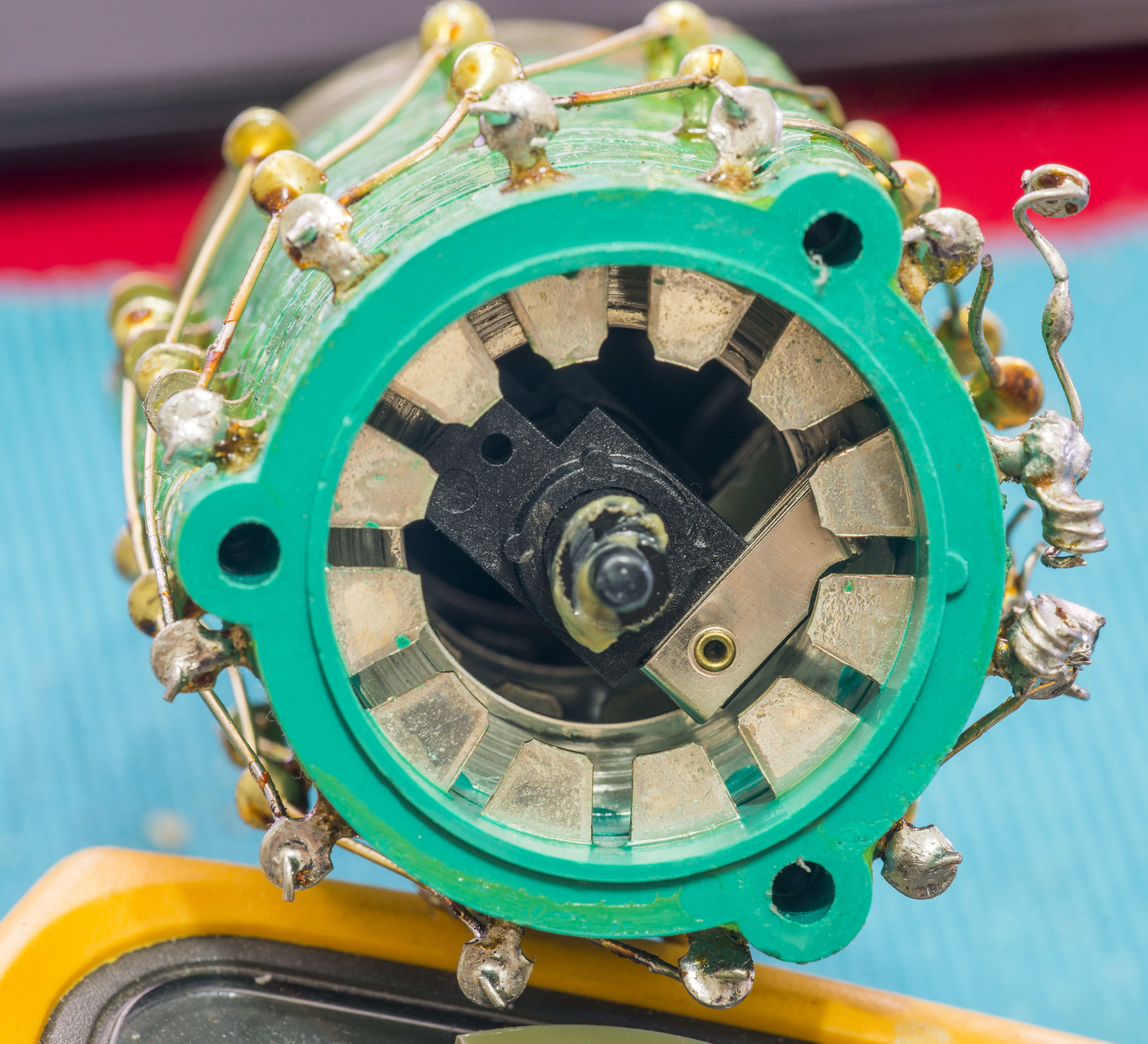
Image 37: Internal construction of 12-pole rotary switch, used in Dec.A
It’s just a arm slider to short top and bottom contact plates, so in no condition there should be short between any of two contacts on same section!
And as expected, after decade switch replacement unit came back to life. Output voltage and division ratio was within 4.7ppm, right from the start. To test better, KVD output must be buffered or null-meter with <10pА of current should be used. Common 6½-digit DMMs usually have 50-100pA of bias current, which translates into ~7ppm error on the unbuffered 70 KΩ output resistance of Fluke 720A divider.
Additional service and repairs
Plastic shafts used to rotate decade switches were replaced as well. Original ones were made of fragile acrylic plastic and cracked already:
In case someone servicing their 720A, I took some measurements for good rod (black plastic) for 3D CAD model:
And files available for download
Performance test
As usual with performance checks and testing, reference standard must have at least 2 (better more) times better uncertainty that DUT. To achieve this ratio, calibrated HP 3458A multimeter will be used. Typical A/D linearity of 3458A is ±0.05 ppm on main 10 VDC range. This meter’s ADC design was verified against quantum primary DC voltage standard, so it does not get better than this.
To be done..
Linearity test
Ratio test
TBD
| 720A Dial Setting | 720A Spec (ppm) | ROUTPUT,Ω | Meas.unc (ppm) | Measurement Ratio Error (ppm) |
|---|---|---|---|---|
| 1.0999999 | 25 k | |||
| 1.0000000 | 25 k | |||
| 0.9999999 | 25 k | |||
| 0.8888888 | 33 k | |||
| 0.7777777 | 25 k | |||
| 0.6666666 | 25 k | |||
| 0.5555555 | 65 k | |||
| 0.4444444 | 25 k | |||
| 0.3333333 | 25 k | |||
| 0.2222222 | 25 k | |||
| 0.1111111 | 25 k |
Other possible version of 720A KVD
One of our contributors, Todd sent few photos of something what supposed to be Fluke 720A, but with very different internals!
No oil-tank resistor network for Decade A, all trimmer network using fixed resistors networks. Different decade switches.
All critical resistors on decades, including key decade A are hermetical type, with black sleeve and marking G-2X KELVIN.
Date codes on resistors are 82xx/83xx, which likely decodes into manufacturing date of 1982,1983. So it’s not an early prototype, but rather a substitute to original 720A design.
If anyone knows details about this, please share.
Conclusion
| Item | Cost | Shipping |
|---|---|---|
| Broken Fluke 720A | $130 USD | $146 USD |
Credits for help and contributions which make this project possible: Todd, lowimpedance, Dr.Frank, Jay_Diddy_B, all forums members, who provided great support and suggestions. None of this would happen without great volt-nut community all over the globe. May the Volt be with you.
This instrument will be used in xDevs.com lab for precision transfers, voltage comparisons and resistors characterization. All readers are welcome to leave your commends and feedback.
Projects like this are born from passion and a desire to share how things work. Education is the foundation of a healthy society - especially important in today's volatile world. xDevs began as a personal project notepad in Kherson, Ukraine back in 2008 and has grown with support of passionate readers just like you. There are no (and never will be) any ads, sponsors or shareholders behind xDevs.com, just a commitment to inspire and help learning. If you are in a position to help others like us, please consider supporting xDevs.com’s home-country Ukraine in its defense of freedom to speak, freedom to live in peace and freedom to choose their way. You can use official site to support Ukraine – United24 or Help99. Every cent counts.
Modified: Oct. 15, 2016, 5:56 p.m.
References
- 20-bit DAC demonstrates the art of digitizing 1 ppm, Jim Williams, April 2001
- Measurement techniques help hit the 1-ppm mark, Jim Williams, 2001
- Minimizing thermocouples maintains 20-bit DAC precision, Jim Williams, 2001
- AN86: A Standards Lab Grade 20-Bit DAC with 0.1ppm/°C Drift, Jim Williams, 2001
- www.amplifier.cd : Fluke 720A page
- Fluke 720A product page
- IET KVD-700 Precision Kelvin-Varley Voltage Divider
- EEVBlog : Repair thread about this 720A
- Testing Linearity of the LTC2400 24-Bit No Latency ΔΣ A/D Converter: Help from the Nineteenth Century
- bbs.38hot.net : Lymex's thread about 720A
- PA4TIM : Fluke 720A KVD article (NL)
- [volt-nuts] Fluke 720A KVD Questions
- JRL VDR307 KVD datasheet