- Intro
- Disclaimer
- Manuals and service information
- Exterior
- Theory of operation, how things work
- Modifications worklog
- Before and after data results
- Backlight modification for display
- Calibration and performance verification
- Conclusion
Intro
After my first article about 6½-digit HP 3456A there was a desire to attempt improvement of later DMM from Hewlett-Packard, Model 3457A. Let’s take a close look on the device in question.
HP 3457A is a versatile system DMM with 7 functions (DCV, TrueRMS ACV up to 450 VAC, DCI, 2W and 4W resistance, Frequency, Period), providing readout with up to 6½-digit resolution (extendable to 7½ over GPIB) with measurement speed up to 1350 SPS. Basic DCV accuracy is specified better than 5 ppm. HP 3457A can also use optional expansion card with multiplexer scanner, to add up to 10 channels for input signals. Being benchtop/system multimter front panel operation have a lot of flexibility and programmable functions. Meter also comes with standard HP-IB/GPIB interface port for remote control/operation. Many of inteface and overall design ideas in this meter are used as a base for later HP 3458A monsters.
This multimeter was introduced to market in 1989, at MSRP $2800 USD.
Disclaimer
Redistribution and use of this article or any images or files referenced in it, in source and binary forms, with or without modification, are permitted provided that the following conditions are met:
- Redistributions of article must retain the above copyright notice, this list of conditions, link to this page (https://xdevs.com/article/hp3457a/) and the following disclaimer.
- Redistributions of files in binary form must reproduce the above copyright notice, this list of conditions, link to this page (https://xdevs.com/article/hp3457a/), and the following disclaimer in the documentation and/or other materials provided with the distribution, for example Readme file.
All information posted here is hosted just for education purposes and provided AS IS. In no event shall the author, xDevs.com site, or any other 3rd party, including HP/Agilent/Keysight be liable for any special, direct, indirect, or consequential damages or any damages whatsoever resulting from loss of use, data or profits, whether in an action of contract, negligence or other tortuous action, arising out of or in connection with the use or performance of information published here.
Details and modifications were tested on actual single HP 3457A unit, and may or may not work in your particular instrument. Beware!
If you willing to contribute or add your experience regarding HP/Agilent/Keysight instruments repairs or provide extra information, you can do so following these simple instructions
Manuals and service information
HP 3457A Operating Guide, May 1986, 03457-90003
HP 3457A Service Guide with schematics/BOM, February 1988, Edition 3 03457-90012SG
HP Journal archive, 1986 issue February
Related component datasheets
LM199-399 ovenized 6.9V buried zener reference
Exterior
This meter was also first in HP system-level flagship line to feature integrated measurements for both direct and alternating current and alternating voltage frequency and period. Previous models, such as HP 3455A and HP 3456A did not have these features.
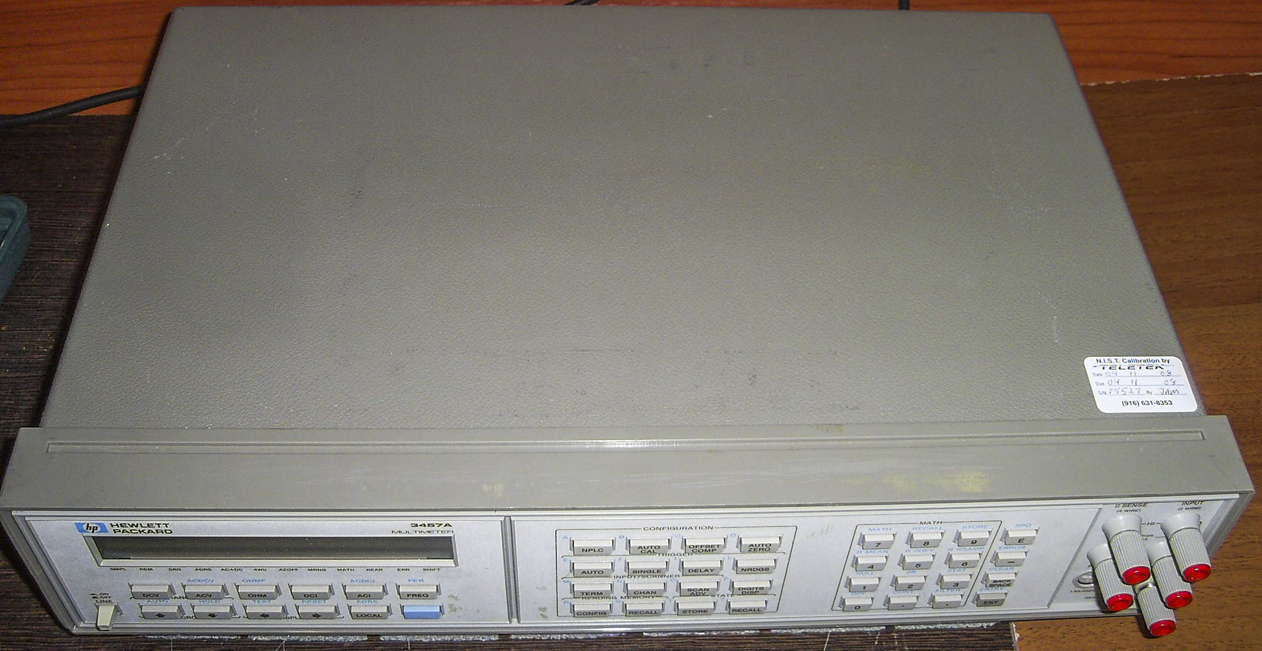
Image 1: HP 3457A overview
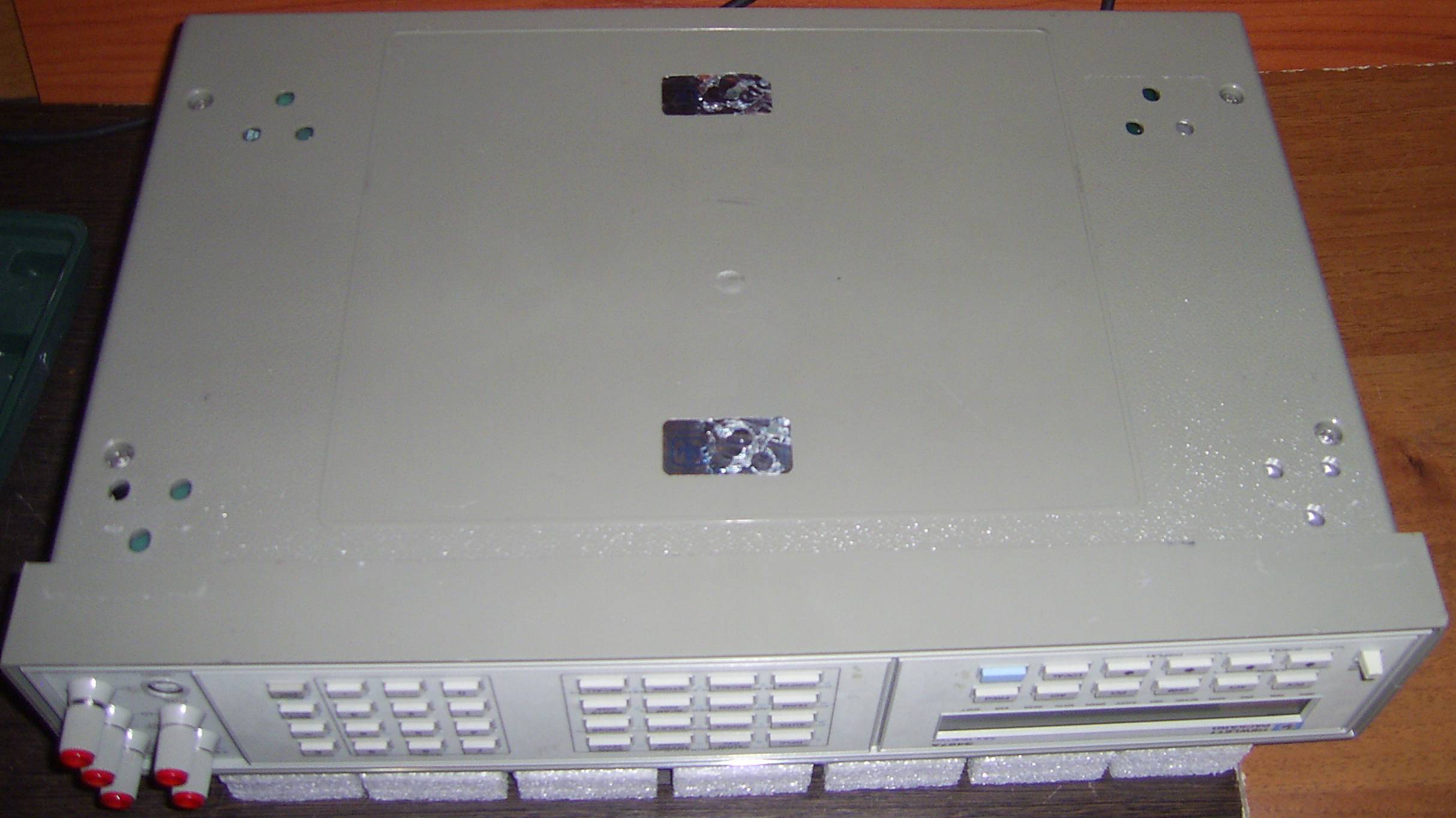
Image 2: HP 3457A bottom side
This DMM also features new “screwdriver-free” calibration to allow electronic adjustments for related functions, using external known reference standard and using onboard ADC to have automatic calculation of affected calibration constants by embedded processor. This means that disassembly and cover removals not required for adjustment and calibration (with few exceptions, covered later). Calibration coefficients are stored in SRAM, which is powered even if instruments powered off, with help of on-board lithium battery. Yes, it also does mean that calibration will be lost if meter too old and battery discharged.

Image 3: HP 3457A internal calibration RAM battery check
Special circuitry protects calibration data from unauthorized or random overwrite. Also calibration commands protected by password, which can be configured by user following special procedure. If password is lost (such as when buying meter on eBay, or previous owner didn’t know the password) it can be reset by jumper toggle on the digital board.
More advanced firmware also greatly improve system use of HP 3457A in automated test jigs and ATE environments. There is possibility to save and recall multiple operation modes with all function settings, even after power cycle. Also each function and mode can be configured either from front panel or remotely over GPIB interface. Special set of macro keys allow programming for frequently used functions/settings. It has keyboard, just like white “Steinway & Sons”, with 44 keys, not counting power switch! For comparison with other HP meters (power switch, rear/front terminal selector, shield selector are not taken into account):
- HP 3456A – 37 buttons
- HP 3455A – 28 buttons
- HP 3458A – 36 buttons
HP 3457A is truly a record holder for HP DMMs in this regard :).
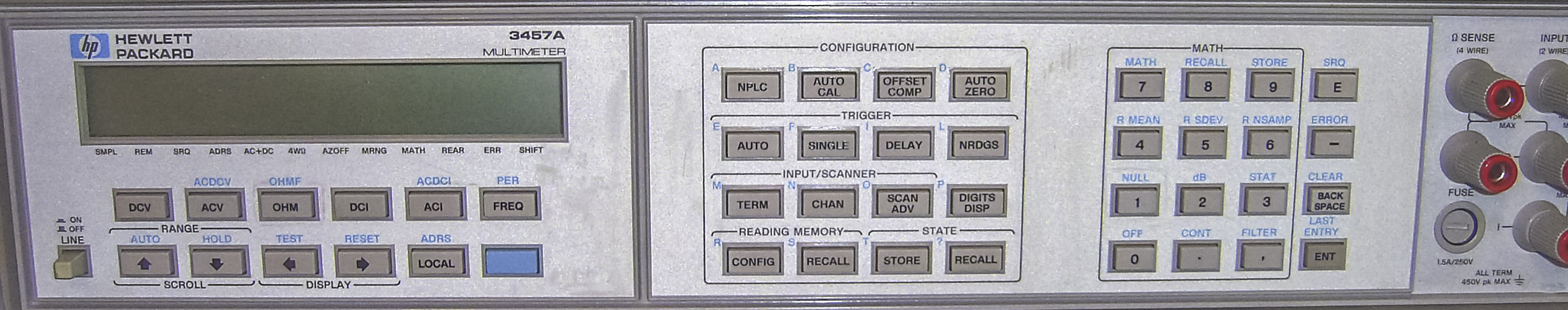
Image 4: HP 3457A front face
Also this is first meter to have “magical” AutoCal button, which corrects:
- 3 GΩ Resistance range (correction for gain and offset)
- Flatness of AC input attenuator for ACV function
- Offset for input amplifier for DCV function
Also as bonus HP promoted ability to get 7th digit from special register access. To my opinion, this was bit overdue addition, as previous model, 3456A even with official specifications without any tweaks can be more precise and less noisy than 3457A. Sounds too good to be true? Check the table below with uncertainty calculations. Data from specs for 24 hour and 90 day period was used . Low ranges like 0.1 and 1 V emulated by using lowest range on 3458A. Areas where 3457A have worse spec marked in red color.
| U, V | HP 3456A, 24h specs, ±V | HP 3457A, 24h specs, ±V | HP 3456A, 90 day specs, ±V | HP 3457A, 90 day specs, ±V |
|---|---|---|---|---|
| 0.1 | 0.0000026 | 0.0000029 | 0.0000058 | 0.0000064 |
| 0.1 | 0.0000049 | 0.0000029 | 0.0000064 | 0.0000064 |
| 0.3 | 0.0000067 | 0.0000061 | 0.0000112 | 0.0000114 |
| 0.5 | 0.0000085 | 0.0000068 | 0.0000160 | 0.0000145 |
| 1 | 0.000013 | 0.0000085 | 0.000028 | 0.000023 |
| 1 | 0.000028 | 0.0000085 | 0.000043 | 0.000023 |
| 2 | 0.000036 | 0.000012 | 0.000066 | 0.000040 |
| 3 | 0.000044 | 0.0000155 | 0.000089 | 0.000057 |
| 5 | 0.00006 | 0.0001225 | 0.000135 | 0.000365 |
| 10 | 0.0001 | 0.000155 | 0.000250 | 0.000540 |
Table 1: HP 3457A vs HP 3456A DCV specifications
Now, we clarified DCV specifications, where 7½-digit resolution could be worth considering. On alternating voltage, 3457A is much weaker than older 3456A. Note that 3456A conversion from ADC is actually 7 digits, but least digit is averaged out and not reported to the front-end, nor the GPIB port remote controller.
3457A allow using multi-channel mux, replacing rear terminal block. There are few options for mux cards, one is high-voltage/high-current slow HP 44491A or faster low-voltage card HP 44492A.
Important feature, absent from previous 3456A, is ability to select front or rear terminal input by remote GPIB command. Even top end 8½ HP 3458A does not have this ability to preserve input signal quality and protection. As result there is no mechanical switch on front panel to change terminal side manually.
Also this unit has least weight in class, due to use of plastic instead of metal as covers material. However it comes at expense of worse noise/RFI immunity. Later mainstream benchtop 34401A meter was also reverted back to metal chassis + shielding covers.
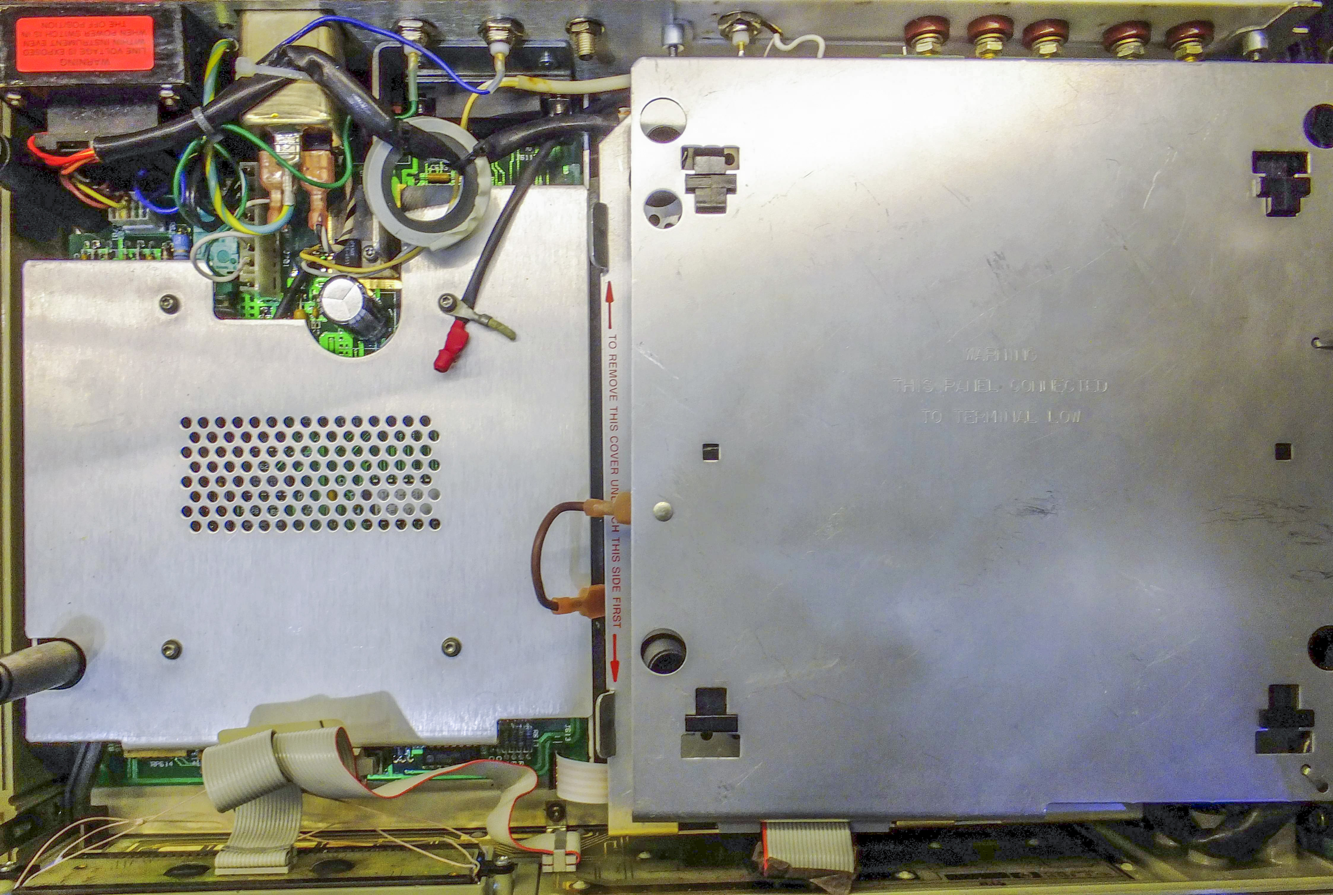
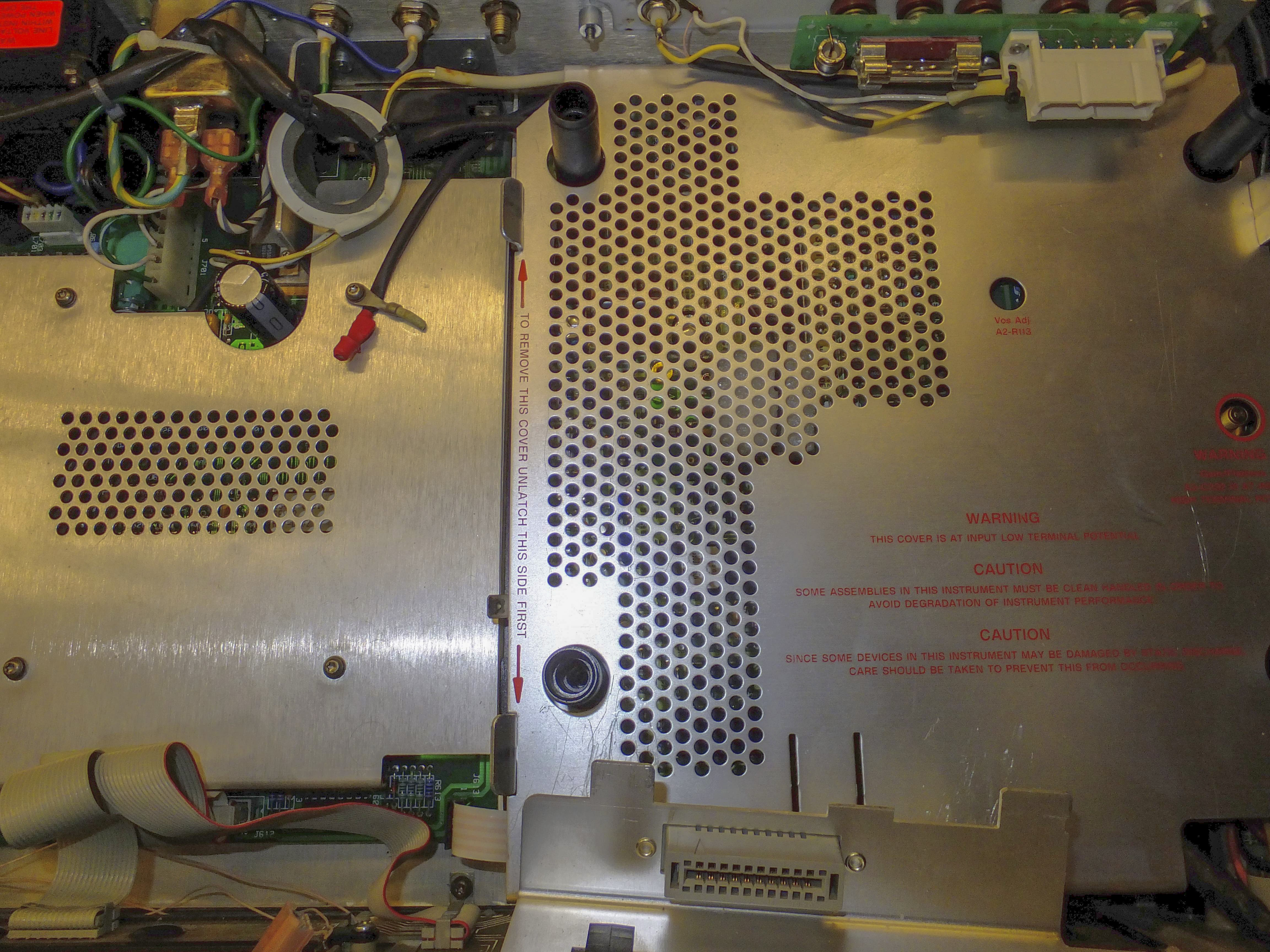
Image 5-6: Inner protection shields

Image 7: Inguard shield removed, revealed AC and front end main board
Overall design architecture is similar to 3456A and also has out-guard power supply/digital/interface and in-guard analog/measurement sections. More details presented below.
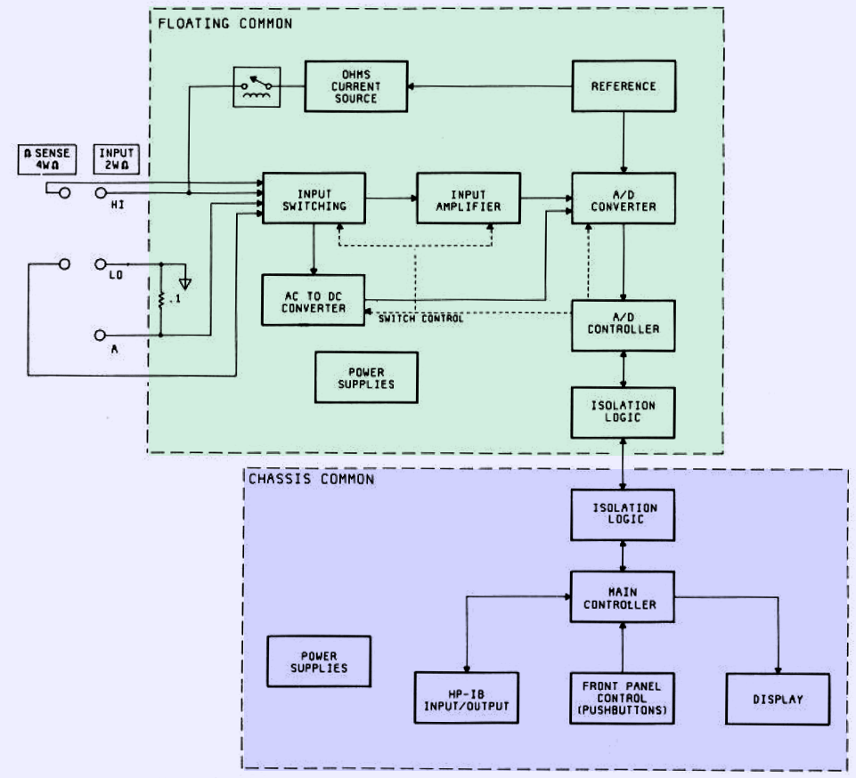
Image 8: Overall block diagram
Inguard isolated section has next circuits:
- input terminals with protection, switching circuits and current shunts,
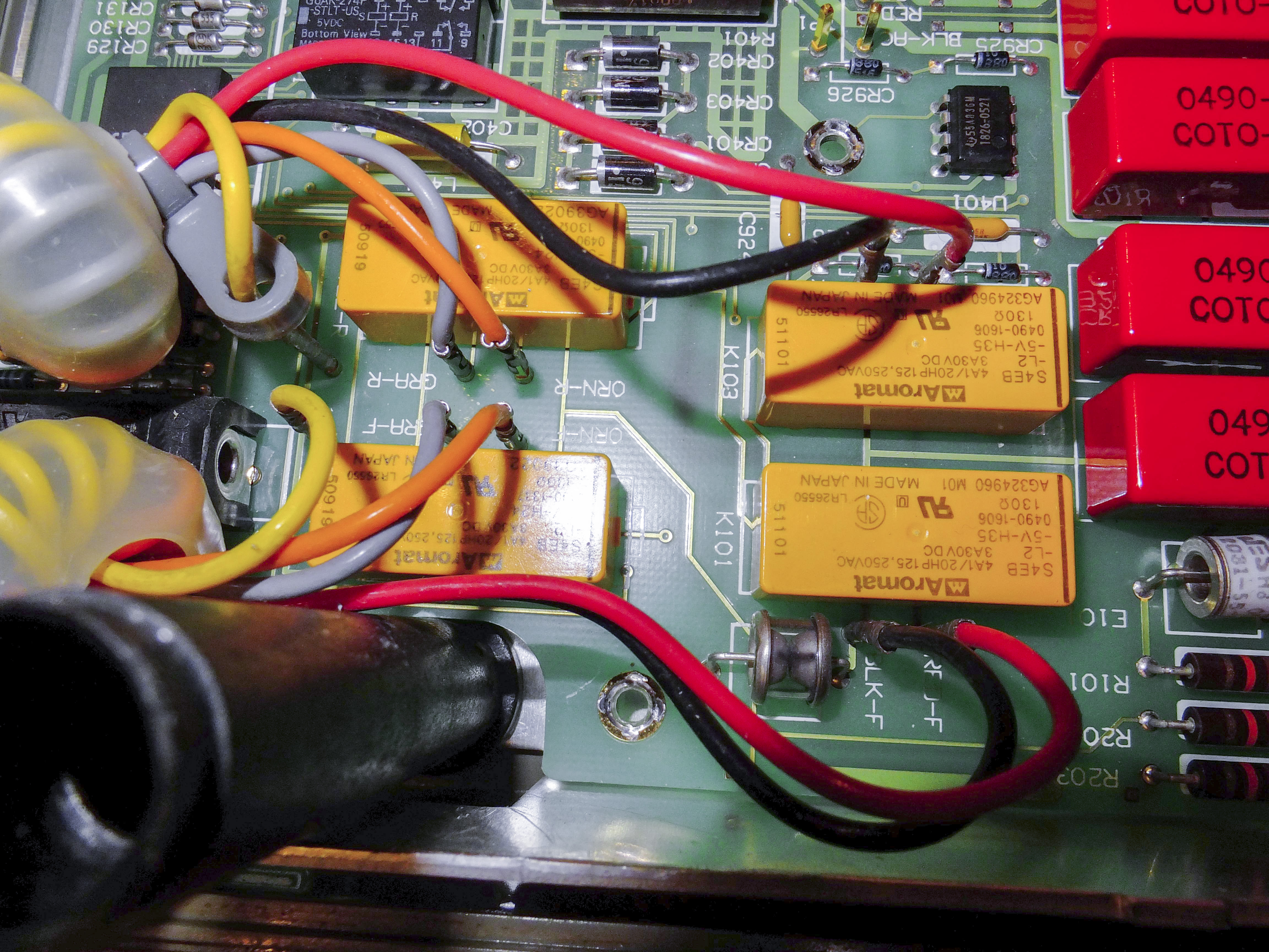
Image 9: Electronic input terminal switching
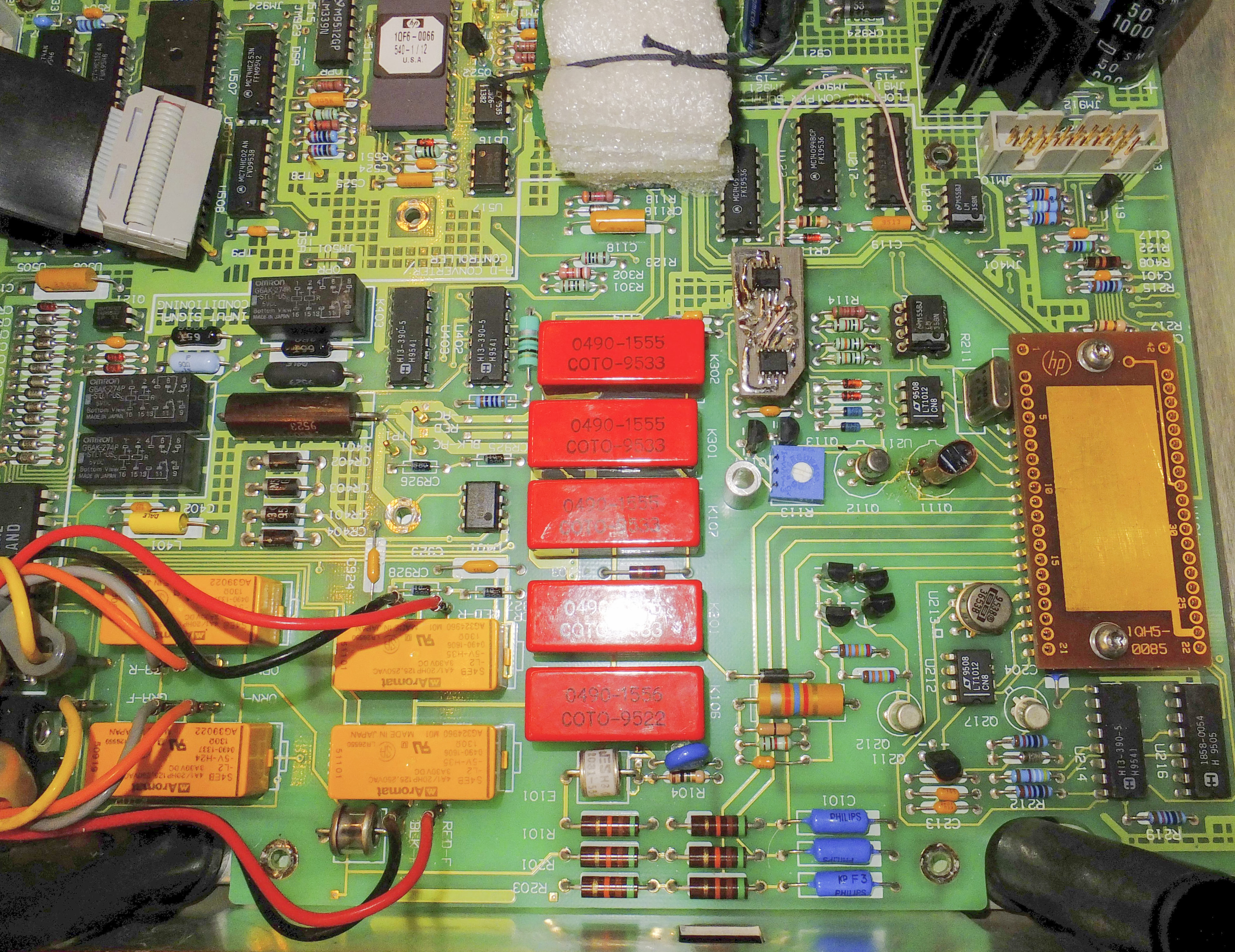
Image 10: COTO relay for front end
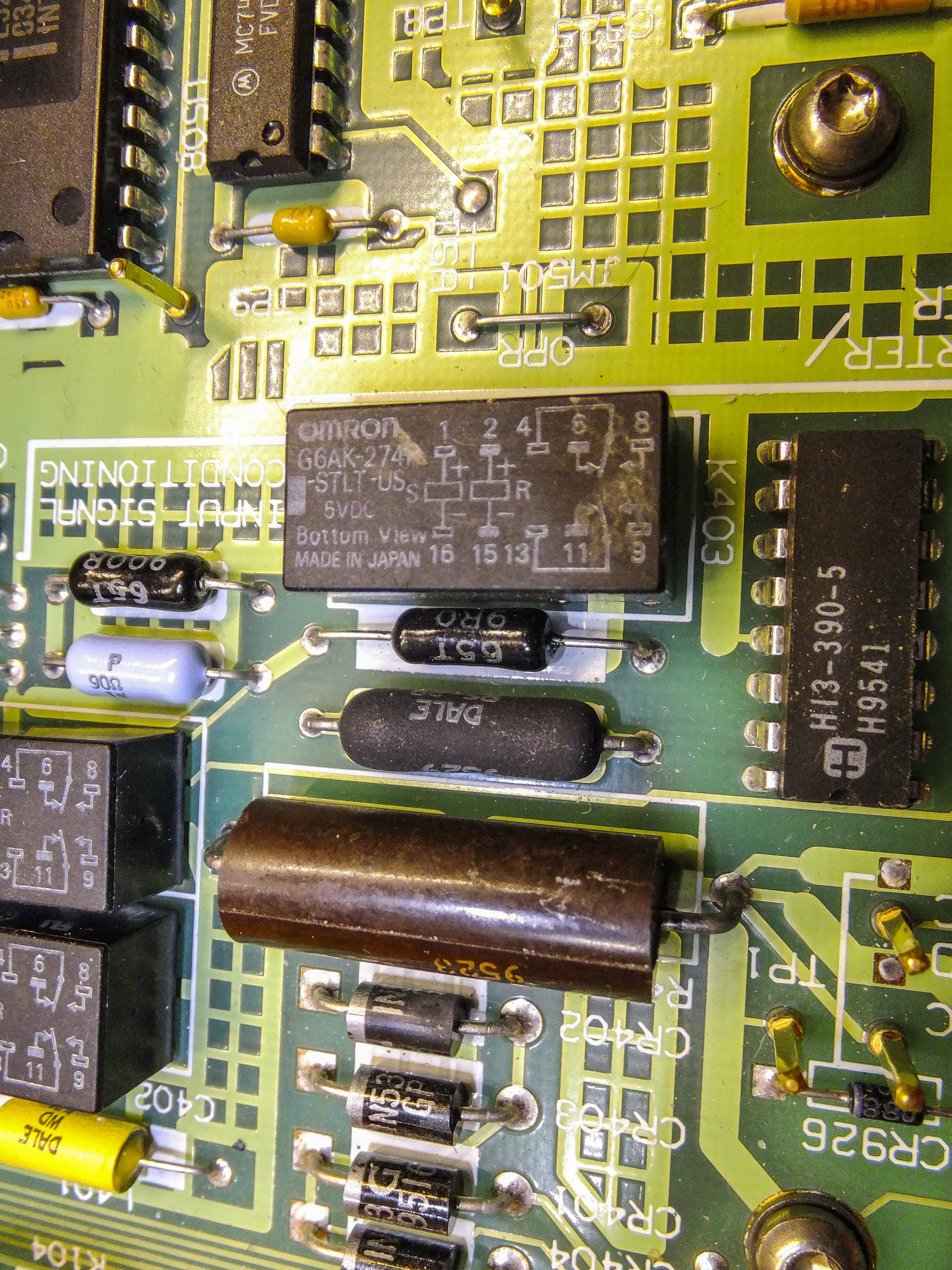
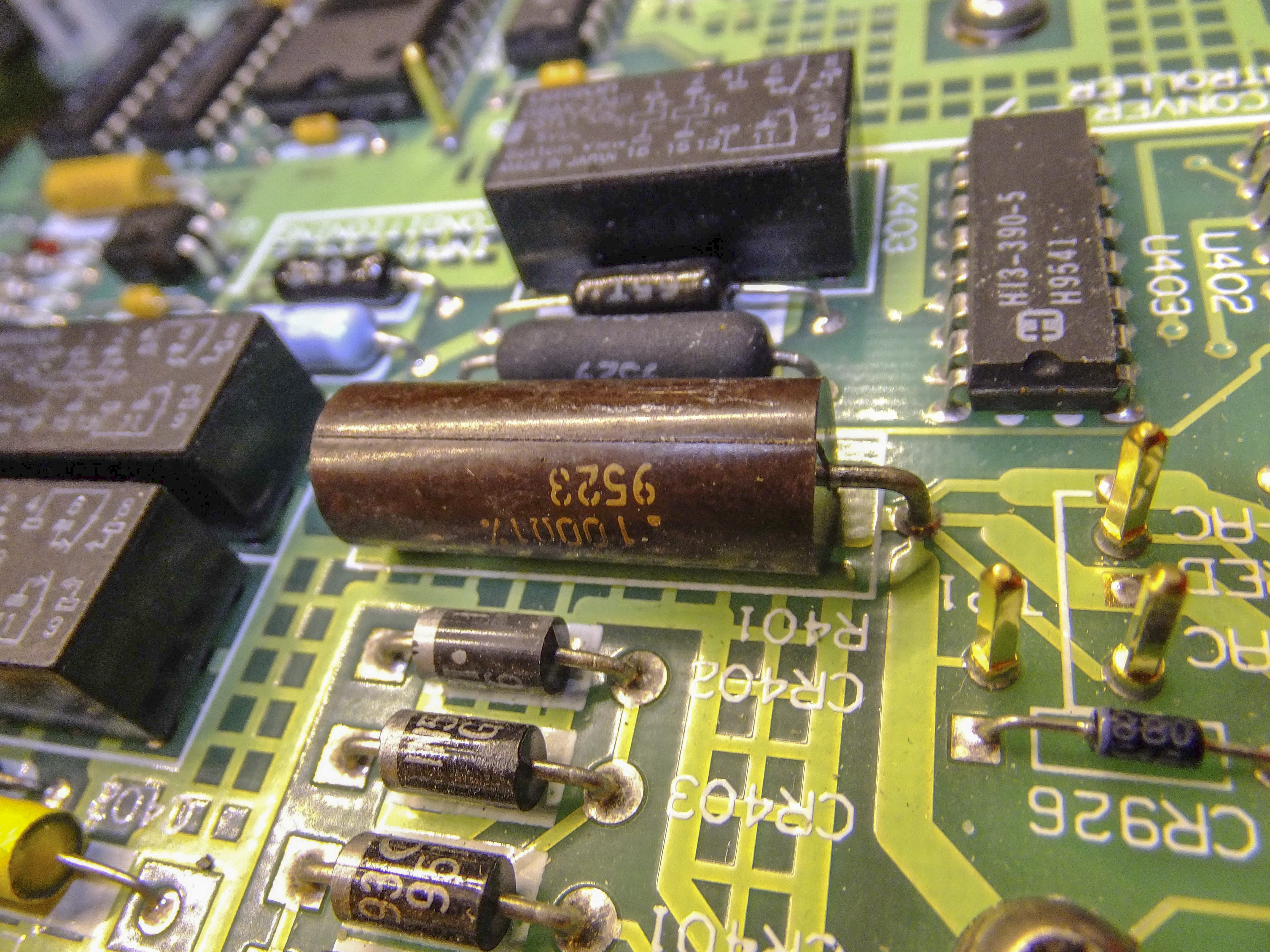
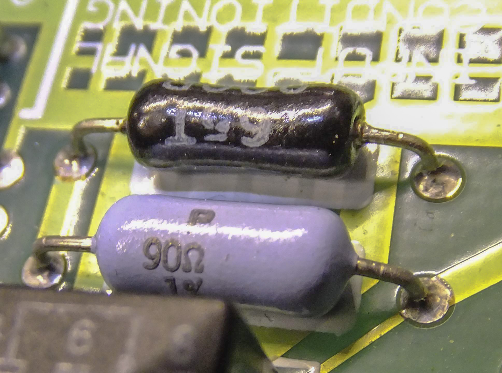
Image 11-13: Resistance shunts for current measurement function
- high-voltage divider 1:100 for DCV function. (also part of hybrid assembly U101),
- input DC amplifier with 1:3.33, 1:33.3 and 1:333 gain,
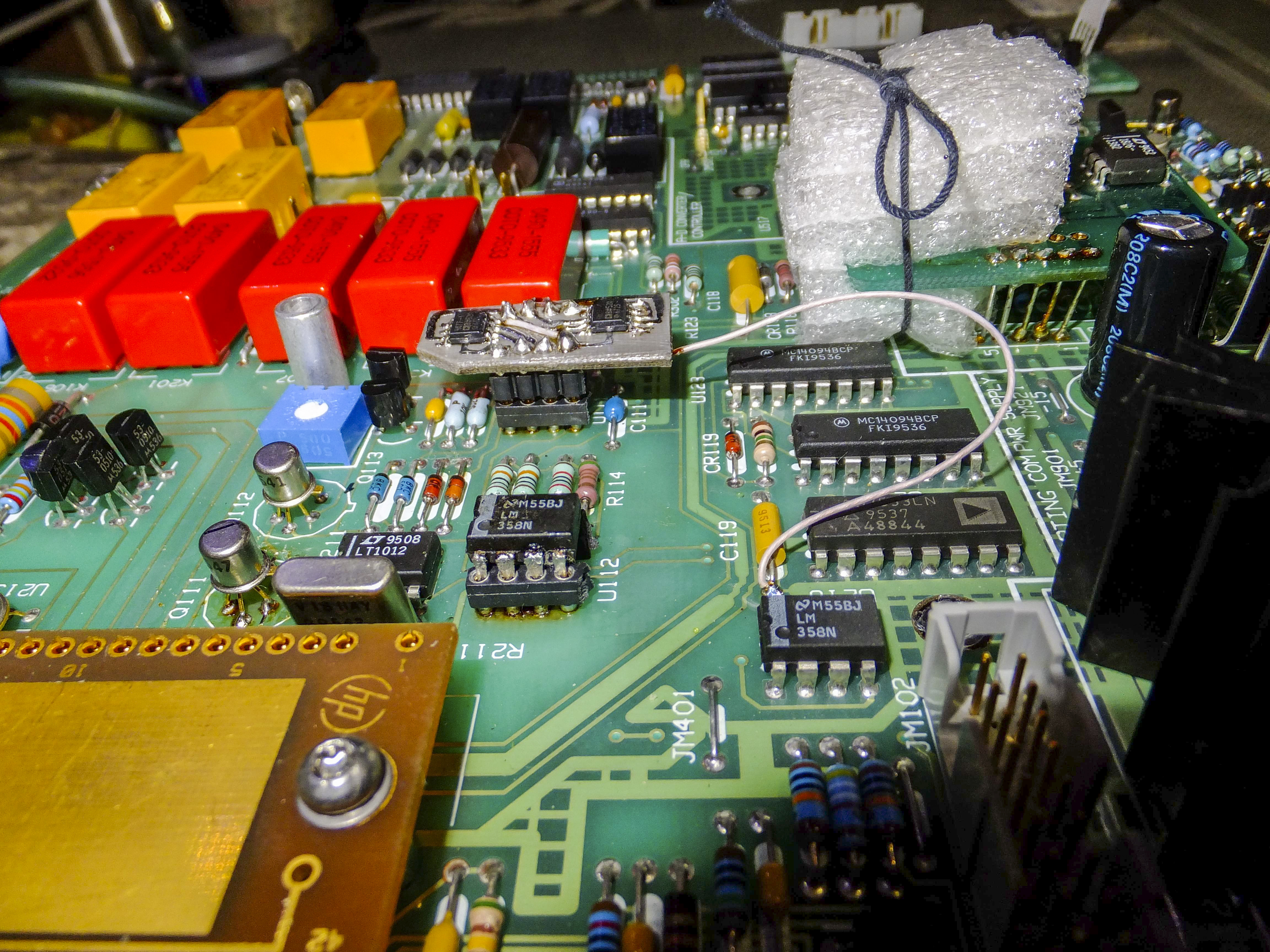
Image 14: Input amplifier after my modifications
- AC/DC converter with it’s own attenuator and amplifier
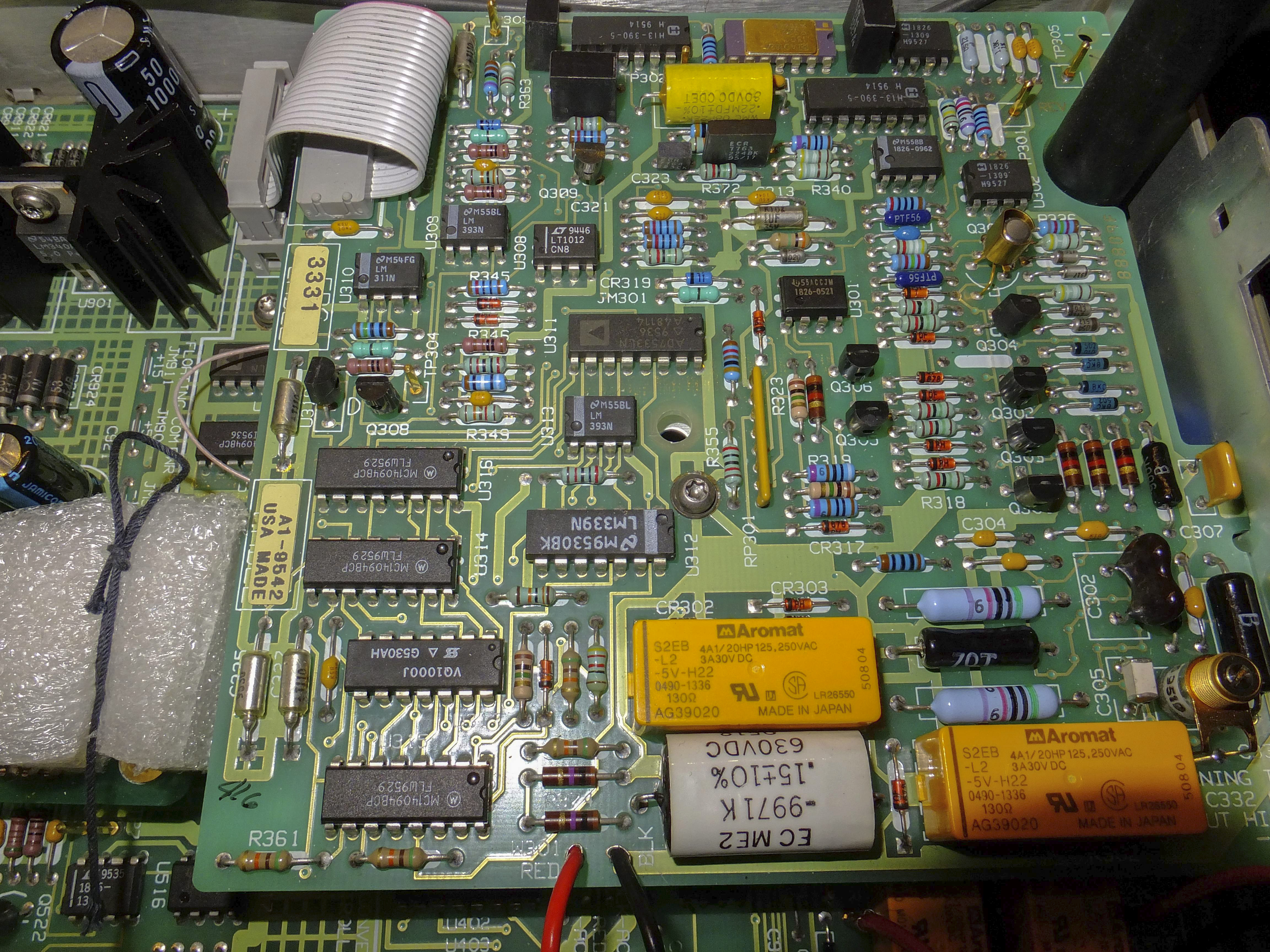
Image 15-16: AC TrueRMS converter board
- Main voltage reference for ADC and current sources for resistance function,
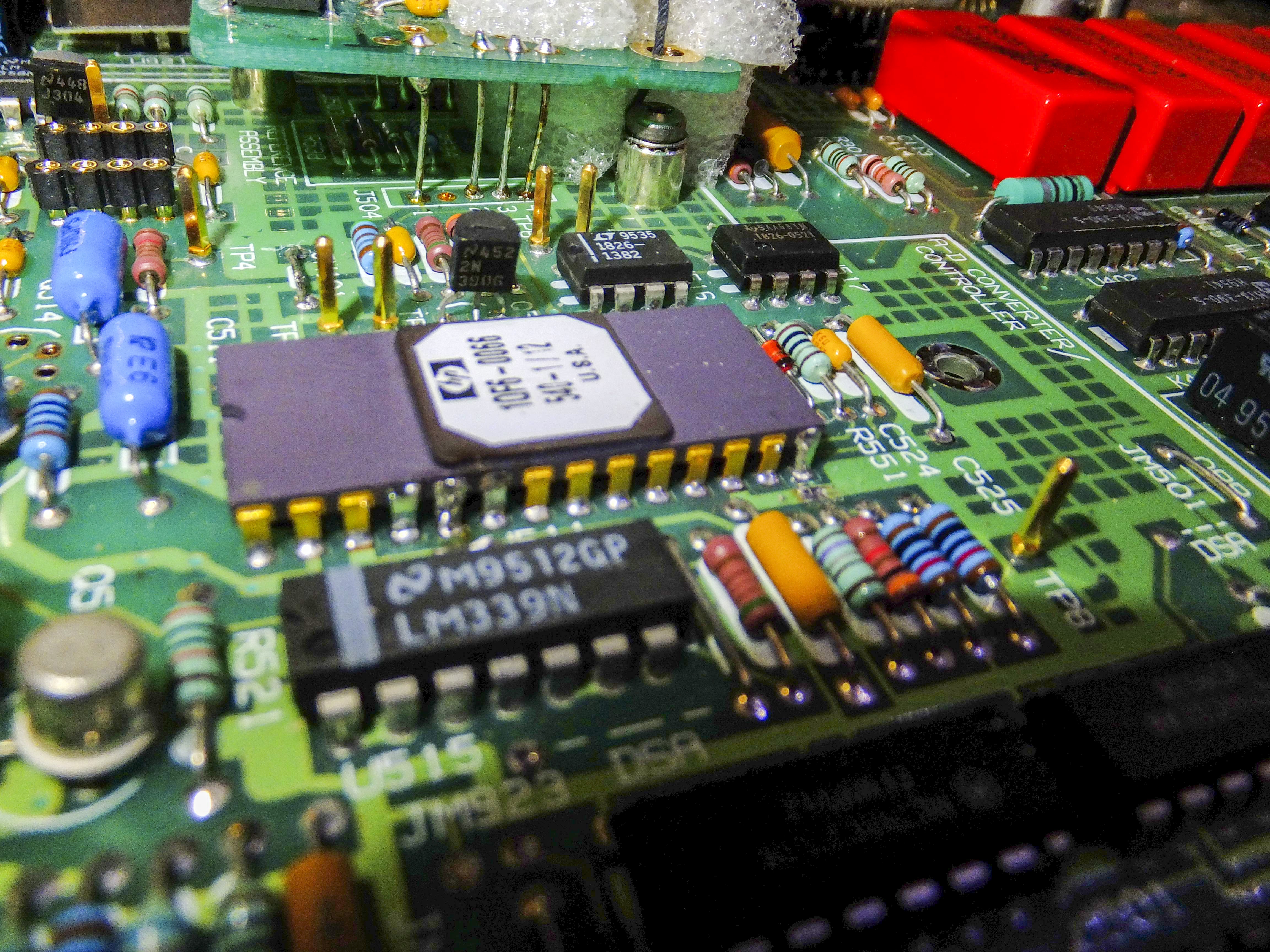
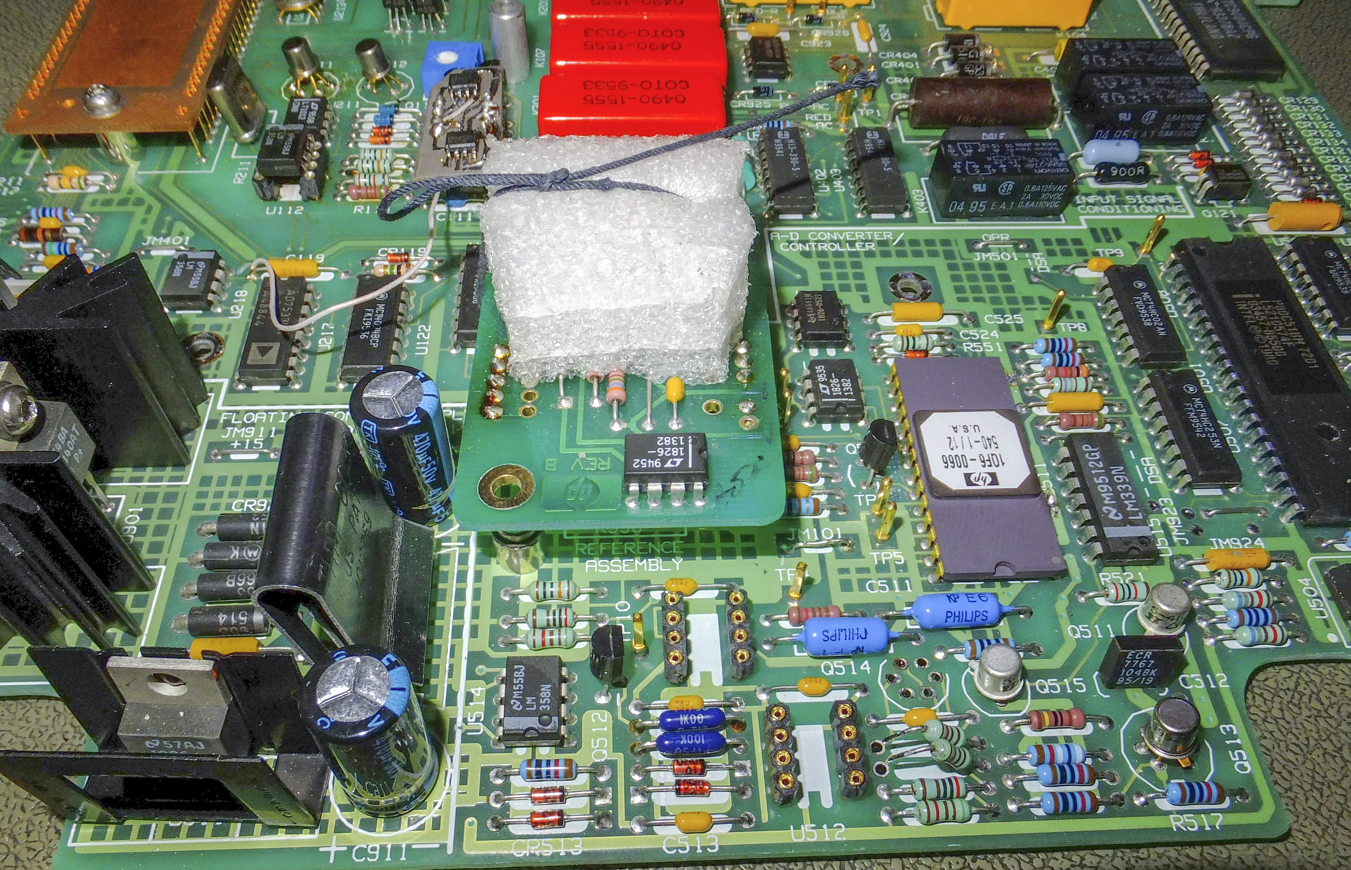
Image 17-18: LM399-based reference module soldered directly to PCBA
- multi-slope integrating ADC itself with control logic,
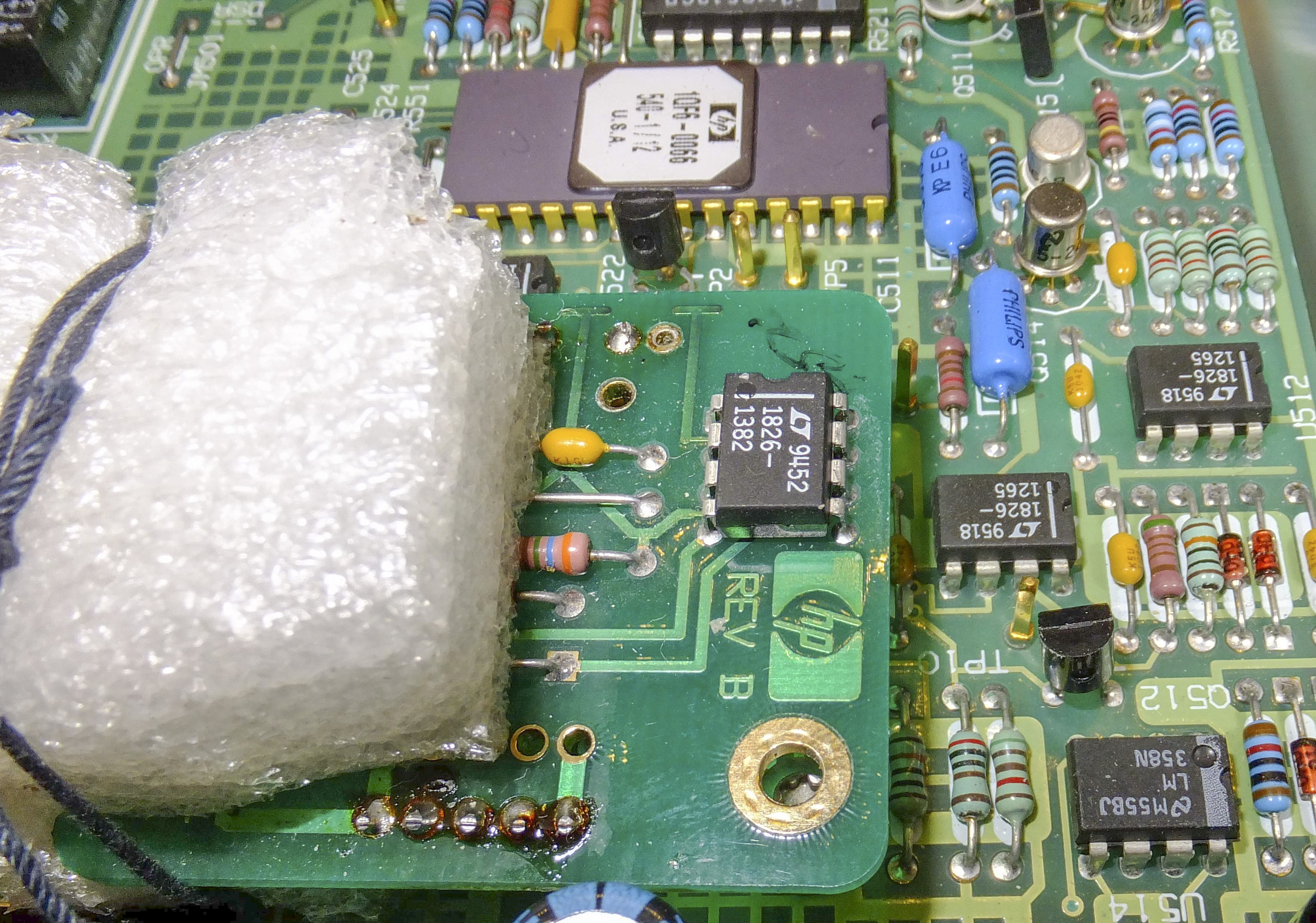
Image 19: LT1122 opamp
- linear voltage regulators and optoisolated interface to outguard digital “brains”.
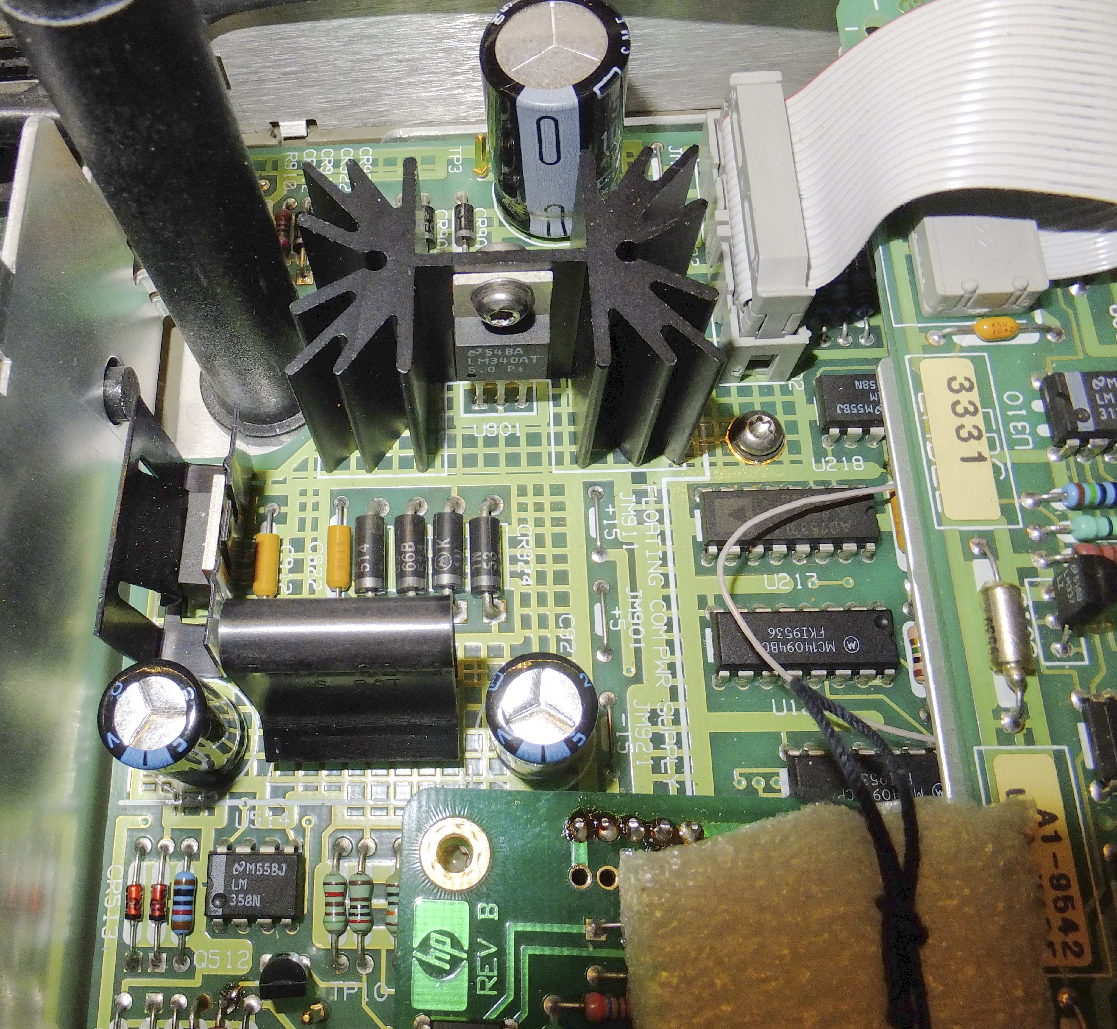
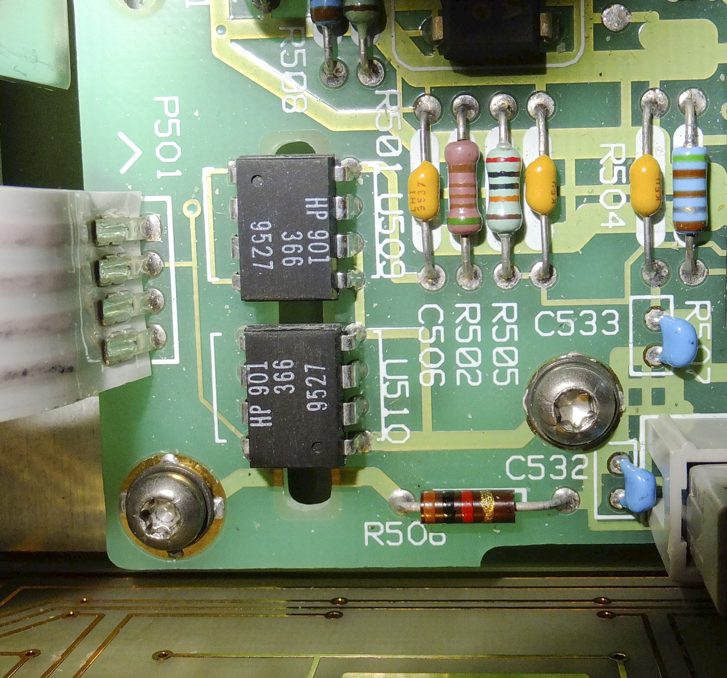
Image 20-21: Linear power regulator and optoisolation interface between the domains
Outguard earth-referenced domain contains of:
- same optoisolated section for interface,
- main processor and it’s memory,
- GPIB interface,
- front panel with display and keyboard,
- main power supply.
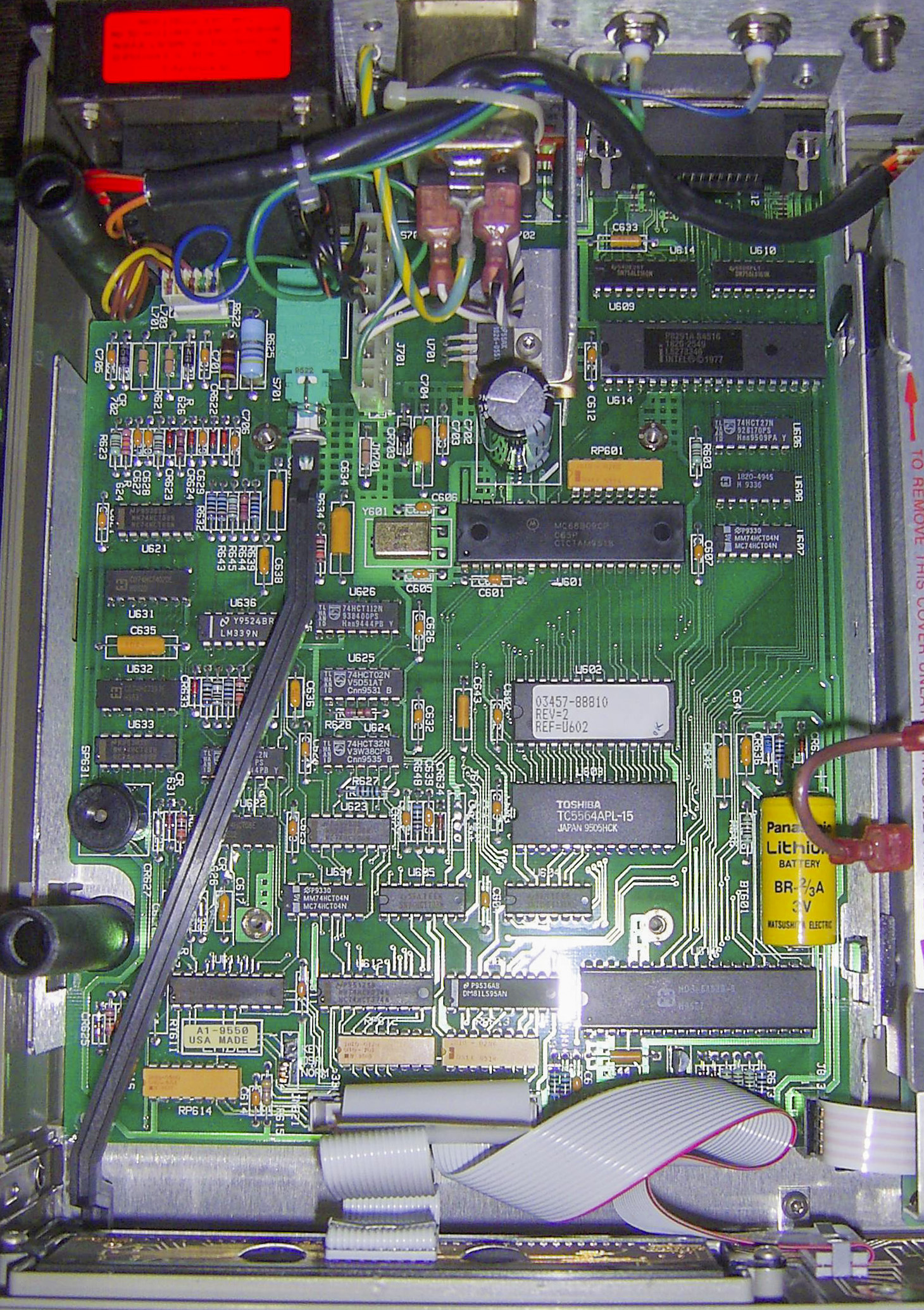
Image 22: HP 3457A digital out-guard section
Theory of operation, how things work
Heart of the meter, ADC built using same principle as 3456A, but now majority of critical components (switches, comparator, current setting resistor networks, logics and clock tree) is embedded in proprietary hybrid ASIC U511:
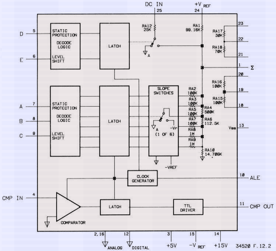
Image 23: HP 3457A U511 hybrid
ADC’s input reference voltage is 10 V. Reference voltage source is same module from 3456A, using LM399 ovenized buried zener circuit. This module even have same HP part number. There is no service manual schematics for this module in 3457A documents, but such schematics available in 3456A.
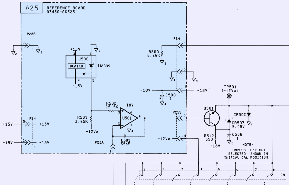
Image 24: Original reference schematics
Hmm, hold on a moment? Input signal scale of the ADC as result is ±10V, but measurement scale is ratio of 3? How did that happened?
This is not a mistake, but a design approach of the 3457A. To scale input signal amplitude input amplifier is always engaged, but has different gain coefficient. On ranges 30 mV, 300 mV and 3 V amplifier gain (later A) is 3333, 33.3 or 3.33 as a result. Higher voltage ranges are even trickier. For 30 V and 300 V additional 100:1 divider is added in front of the amplifier, which is configured for A=33.3 or 3.33.
Most of key circuitry in contained in another proprietary ASIC – HP U101.
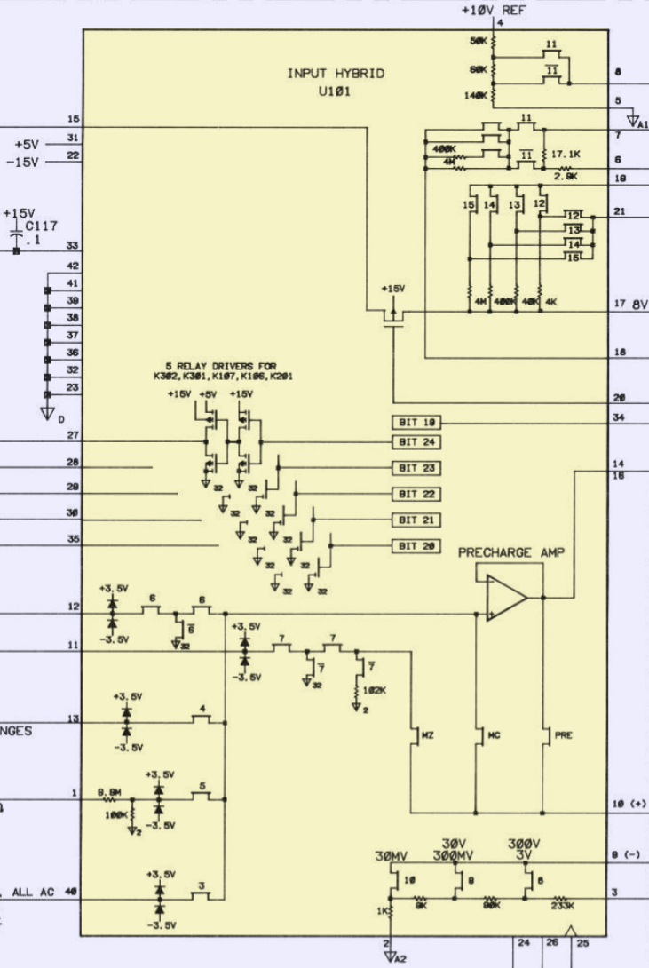
Image 25: U101 hybrid design block diagram
As result of such complex arrangement 3457A front-end does have more input noise compared to 3456A, and also does not have 1:1 direct path on any of the DCV ranges. Closest to the base range is 3 V, which is not best case for sensitive measurements, such as 7V reference output.
Going back to input amplifier, it’s based on combined schematics of two matched FET pairs, Q111 and Q112 together with dual opamp U111 (TL072).
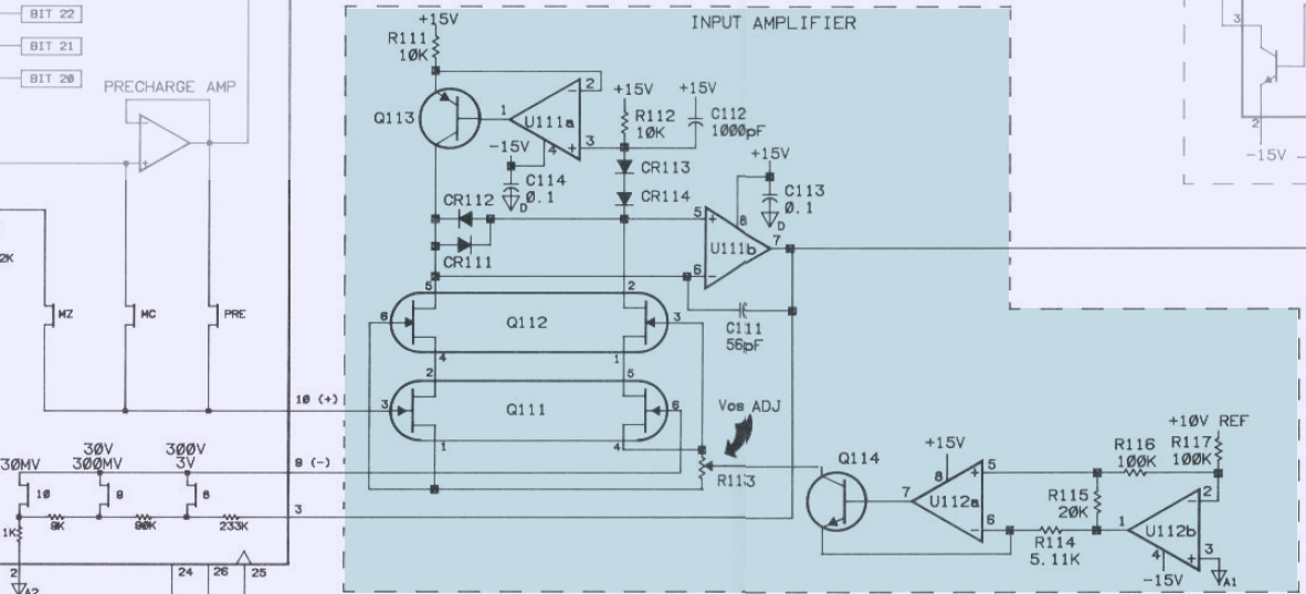
Image 26: Modifications for 3457A input amplifier
Main goal of modifications was to reduce noise in DCV function, so let’s take close look on two main sources of such noise, input amplifier front-end and ADC itself.
Input amplifier have U112,Q114 which set and maintain stable current on the FETs. U112b used to invert voltage reference level +10V to negative -12V, -2V of which going to R115 (top terminal have -10V, bottom terminal -12V). This stable 2V level supplied to voltage-current converter around U112a,Q114 with current setting by resistor R114. 2V over 5.11 kΩ produce current around 400 µA , or about 200 µA per side. R113 help to maintain balance when input is shorted, or in other words – cancel out voltage offset.
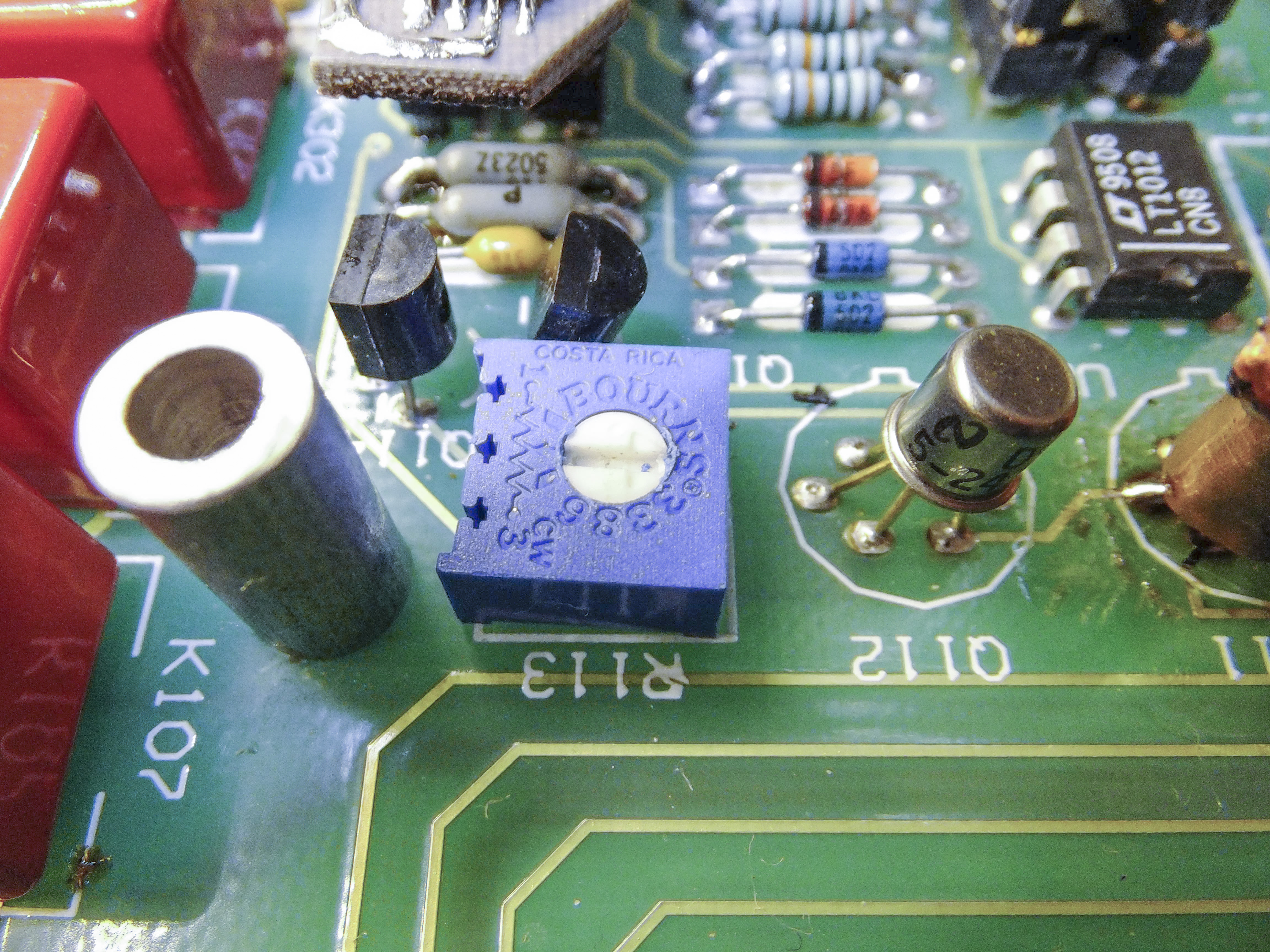
Image 27: R113 trimpot adjutment for offset correction
There is special procedure for voltage offset correction, but we will get back to it later.
Resistors R111 and R112 act as load and define gain of the FET-amlifier, while current mirror circuit around U111a,Q113 balance equal DC current between the sides, increasing overall gain as result. Actual amplifier part is Q111, and Q112 help for constant voltage between source and drain of Q111. Diodes CR113, CR114 ensure operation of the current mirror with their voltage drop. CR111 and CR112 protect opamp U111b from overload conditions. This opamp provide most of the gain. Worth to note, that this operational amplifier must be stable with both high and low gains, and as we will see later, most troublesome range for stability is 3 V.
It’s clear, that due to custom hybrid ASIC design, we cannot do much in terms of noise, other than improving stability and quality of the supply voltages. So main interest go to other possible noise sources. Suspects are listed below:
- Pair Q111 and operation of this stage (usually higher working current produce less noise).
- U111
- U112
- Noise on +10V reference voltage. (Even with shorted input, when reference noise irrelevant to ADC! This is due to use of reference voltage for input amplifier operation)
- Much less probable – noise from Q112, Q113, Q114, CR113 and CR114.
So in next chapter we will try some experiments for first four circuits.
But before that, take a look on the ADC itself.

Image 28: HP 3457A ADC
Here is composite integrator Q514,U512 with integrating capacitor C511 and pre-amp for comparator circuit U513,R513,R515. Everything else, like charge rate switches, counters and control logic integrated on U511 hybrid ASIC, or perform auxilary roles (reset comparator U515a, switches). These auxiliary circuits do not affect noise performance of the ADC.
Likely, largest contributors to noise performance are
- C511
- Q514
- U512
- U513
Now we have just two more things to do.
Modifications worklog
Some might think that HP 3457A is ancient technology instrument, and it should be very easy just to swap some opamps and components to modern high-performance devices, and everything will become much better. Just like replace CPU and GFX in computer from old Pentium 4 to modern Core i9, eh?
Well, in analog design world things are much more complicated, and swapping components without understanding what the circuit do is a road to a disaster and broken equipment.
Upgrades and modifications on this HP 3457A were attempted for long time, multiple times for period over a year.The longest process was getting required component samples. It’s not easy to get high-performance components which are not stocked in regular retailers, and also there is a lot of counterfeit on Aliexpress (more than half of sales, in my own experience)
Another time consuming challenge – complex approach type. It’s not possible to isolate just one circuit and test it’s performance, without rest of the instruments. That mean each modification test is full reassembly, few hours warmup and then multiple hours for datalogging (each low range separately!). Add time to assemble/disassemble, replace parts, etc.
I tried to combine modifications in groups, so can test multiple things at same time, when that was possible. Often modification result was negative (performance got worse), so reverse modification was required to determine what went wrong. So to save time for a reader, I’ve collected all modifications (that I remember) into a table, with summary result if it helped the instrument or not, and also decision on each modification. Hope this can be helpful for other HP 3457A owners.
| Modification type | Successful? | Noise reduced? | Modification result |
|---|---|---|---|
| Add backlight for LED display | Yes | No impact | Applied |
| Add internal temperature sensor for in-guard section | Yes | No impact | Applied |
| Additional ferrite common mode choke between transformer and in-guard section | Yes | Looks like yes | Applied |
| Improve thermal isolation for LM399 reference | Yes | Yes | Applied |
| Replace connectors to hard soldered connection for VREF PCBA | Yes | Looks like yes | Applied |
| Increase capacitor value C901 to 2200 µF | Yes | No difference detected | Reverted |
| Increase capacitor values C911 and C921 to 470 µF | Yes | No difference detected | Applied |
| Additional ceramic capacitor 4.7 µF right on pins 3 and 5 of the U511 | Yes | Worse | Reverted |
| Same modification as above, but 0.1 µF | Yes | Still worse noise | Reverted |
| Replacement of U512 and U513 to LT1122 | Yes | Yes | Applied |
| Attempt to remove Q514 | Yes | Worse | Reverted |
| Attempt to increase preamplifier gain (U513) | Yes | Worse | Reverted |
| Replaced U111 to ADA4077 | Yes | Yes | Applied |
| Replaced U112 to AD706 | Yes | Yes | Applied |
| Replaced Q111 to pair 2SK30A | Yes | Yes | Applied |
| Increase current thru Q111 | Yes | Partially better, but worse on 3V | Reverted |
| Replaced U501 to AD707 | Yes | Yes | Applied |
Table 2: Modifications log
Thermal sensor and mounting location:
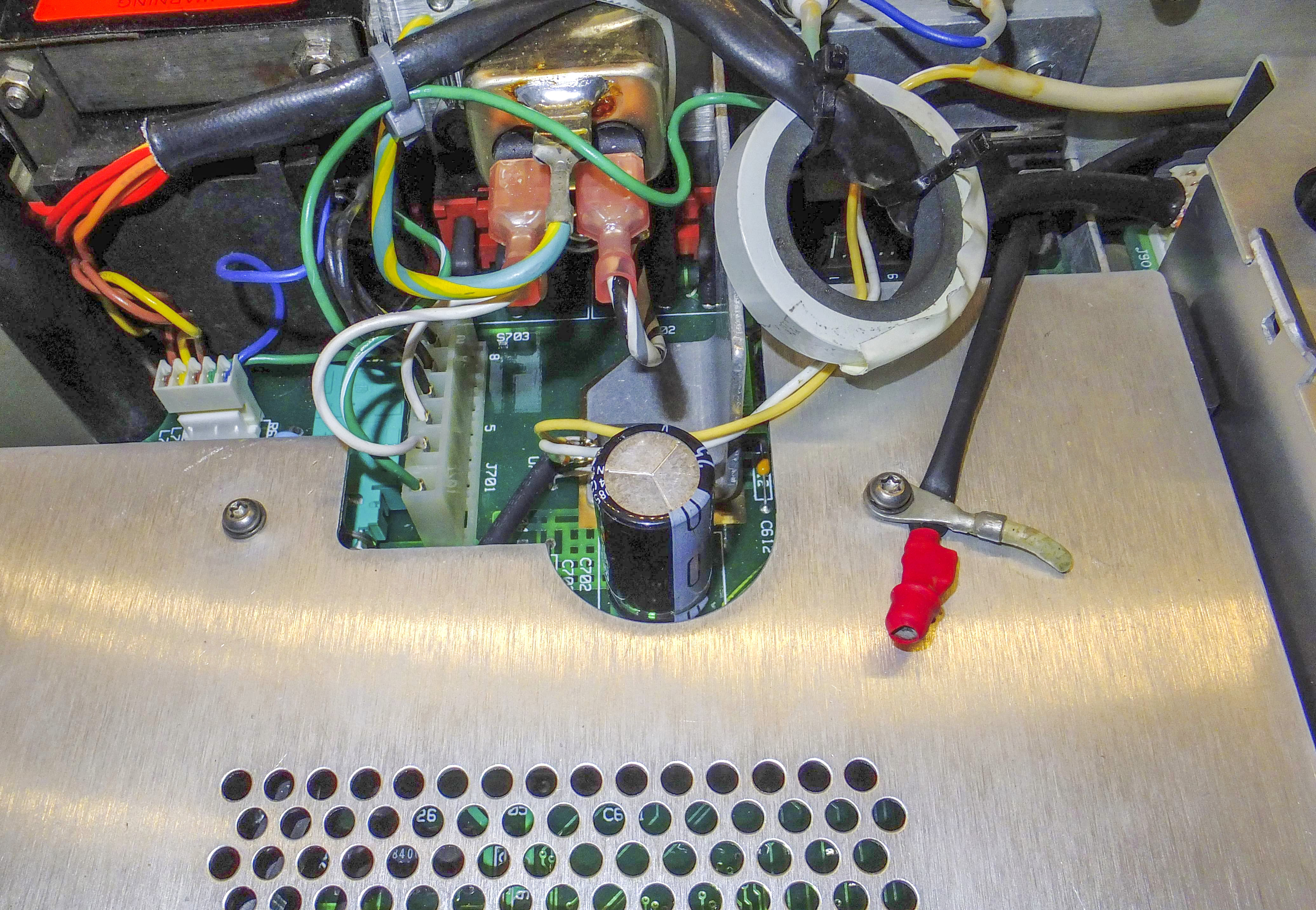

Image 29-30: Additional temperature sensor and output BNC port for it
Let’s go thru rest of the modifications, targeted on measurement noise reduction.
Improve thermal isolation for LM399 reference covered in detail in my article about HP 3456A meter.
Adding common mode ferrite choke and removing connections between reference module and mainboard does not need additional explaining either.
Since all microchips in HP 3457A are in thru-hole type DIP style, all replaced components are carefully desoldered and positions on the board populated with high-quality collet-type sockets. This allows to experiment easy without risk of damaging the board taking everything apart for each component swap. Operational amplifier LT1122 have both variants for DIP8 and SMT packages, so they can be installed instead of original LT318 (U512 and U513) with ease.
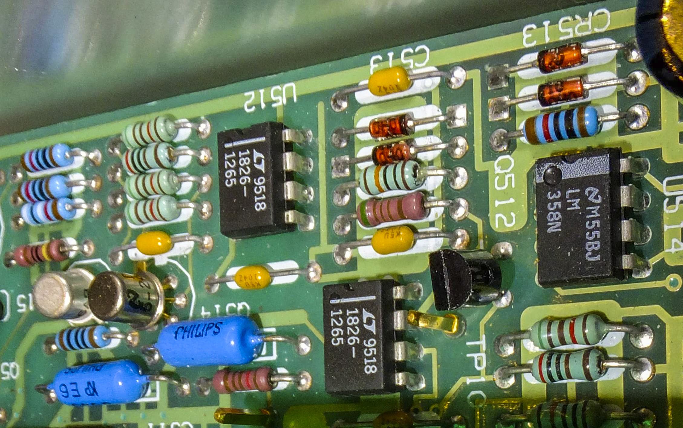
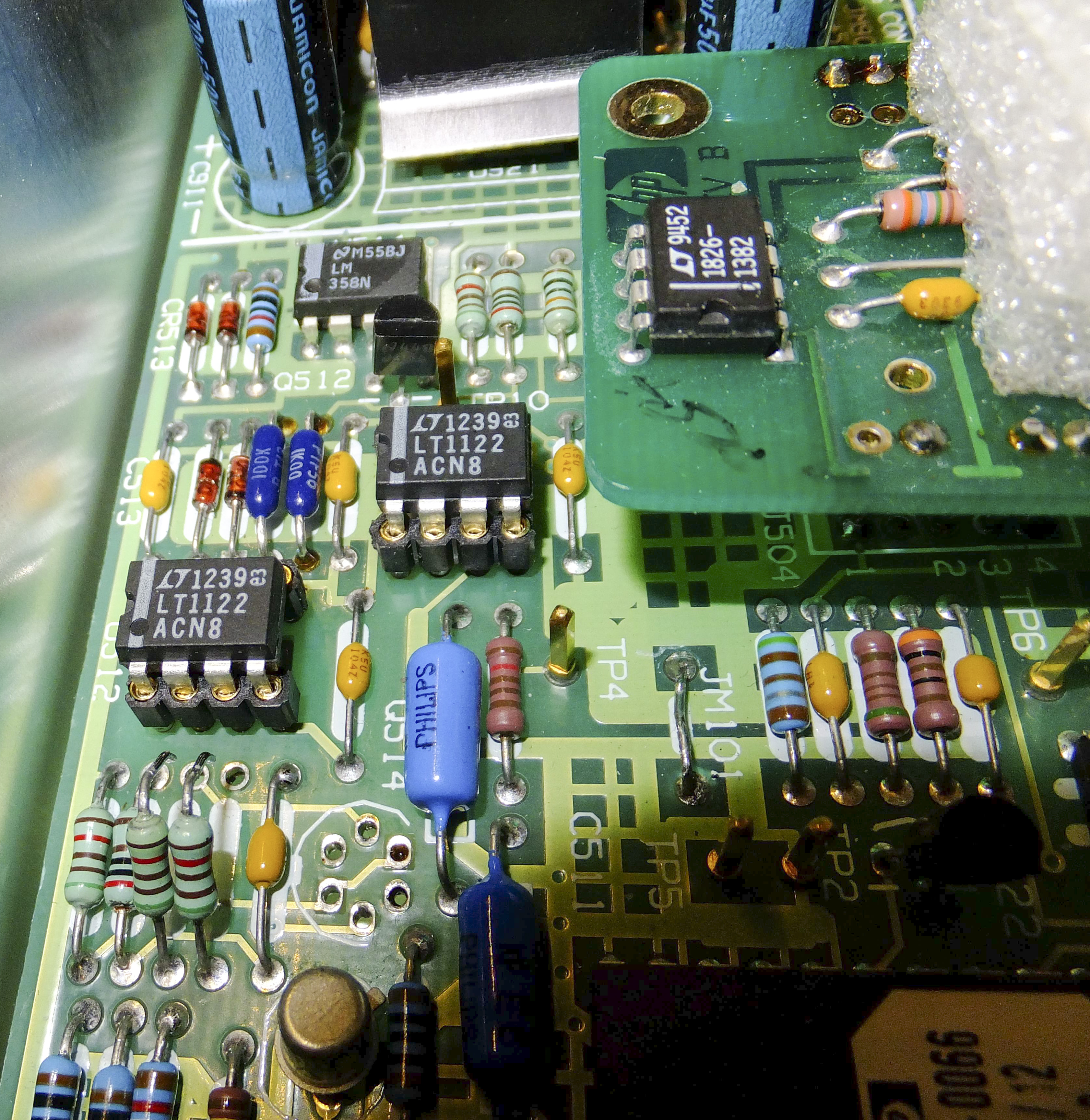
Image 31-32: LT1122 circuitry near DCV reference
On second photo you can see removed resistors, missing Q512 and R513 1 kΩ instead of factory 5.11 kΩ. All this had to be reverted to original state in the end result, as noise only got worse.
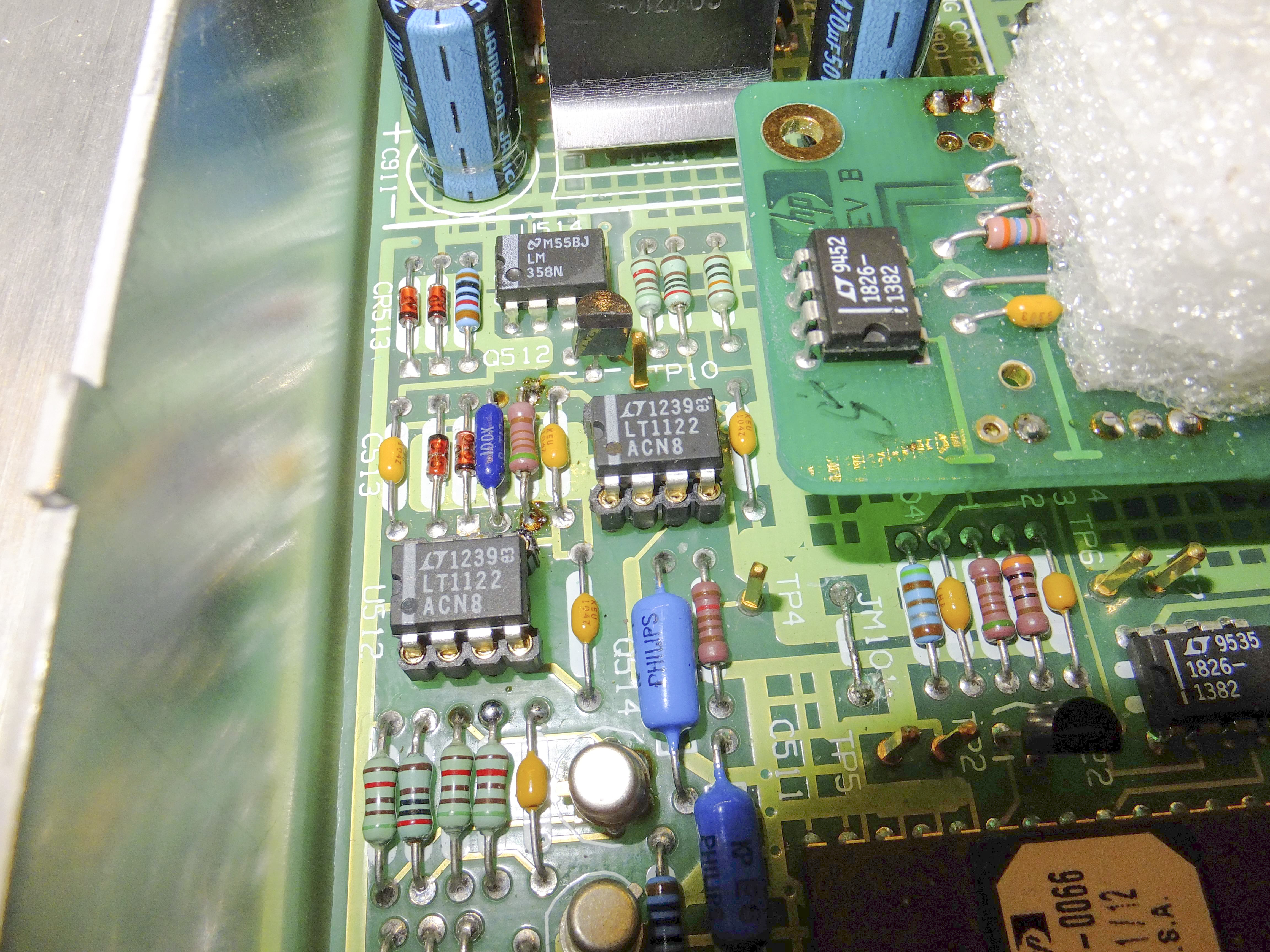
Image 33: Replaced opamps with collet sockets
Situation with U111 is more difficult, as I got only single-channel version ADA4077-1 but original TL072 is dual opamp component. I did not want to wait, so adapter board bodge to the rescue to fit two chips in DIP8 socket.
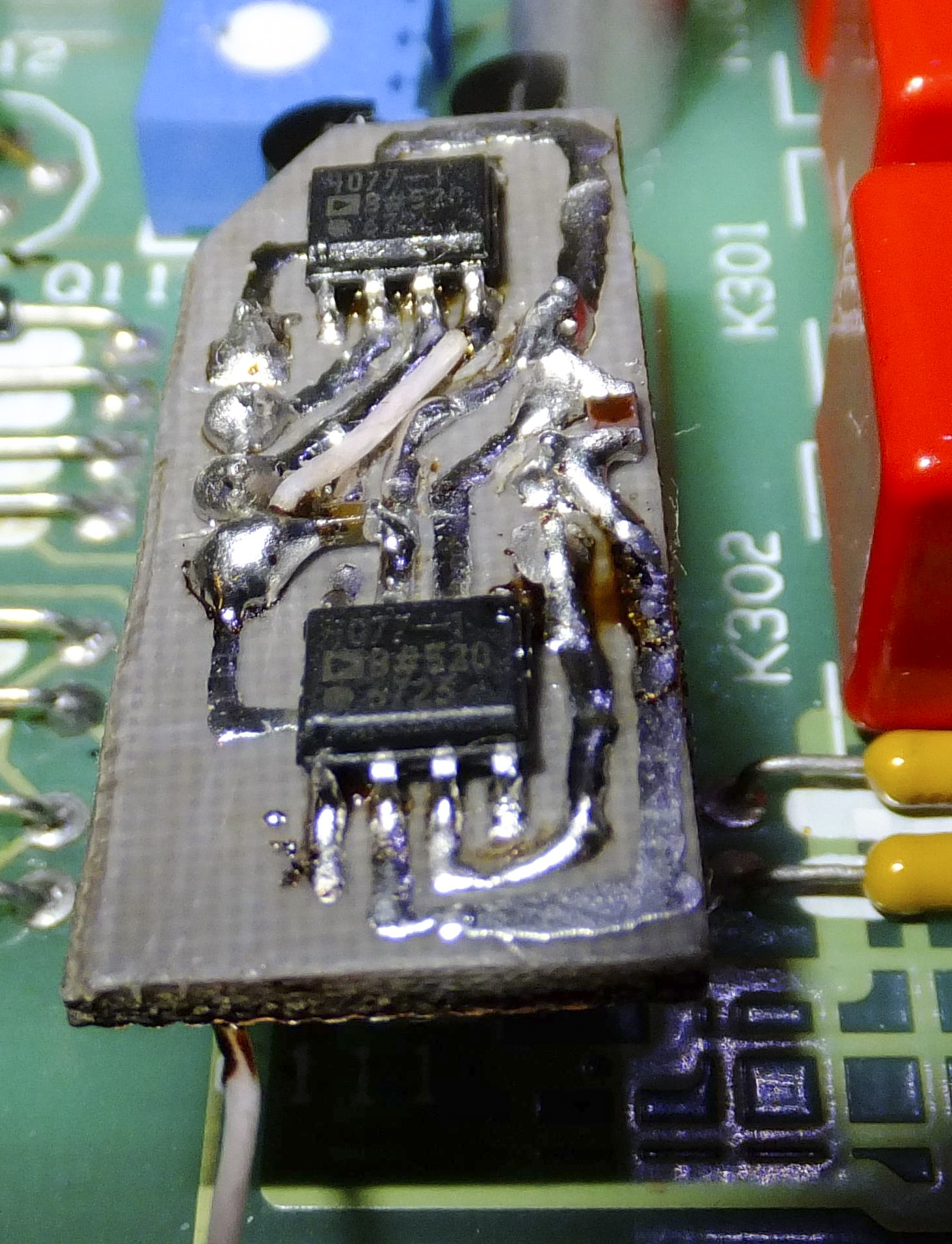
Image 34: ADA4077 with DIY adapter board
PCB Layout:
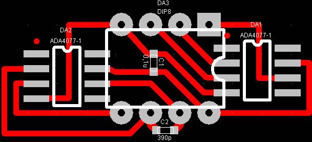
Image 35: Adapter PCB layout
To use AD706 in U112 position together with AD707 in position U501 I’ve used factory adapters SO8/DIP8. When I tried to increase current thru FETs it revealed low quality of R114, at best about bad quality of USSR-made MLT-series general purpose resistors.
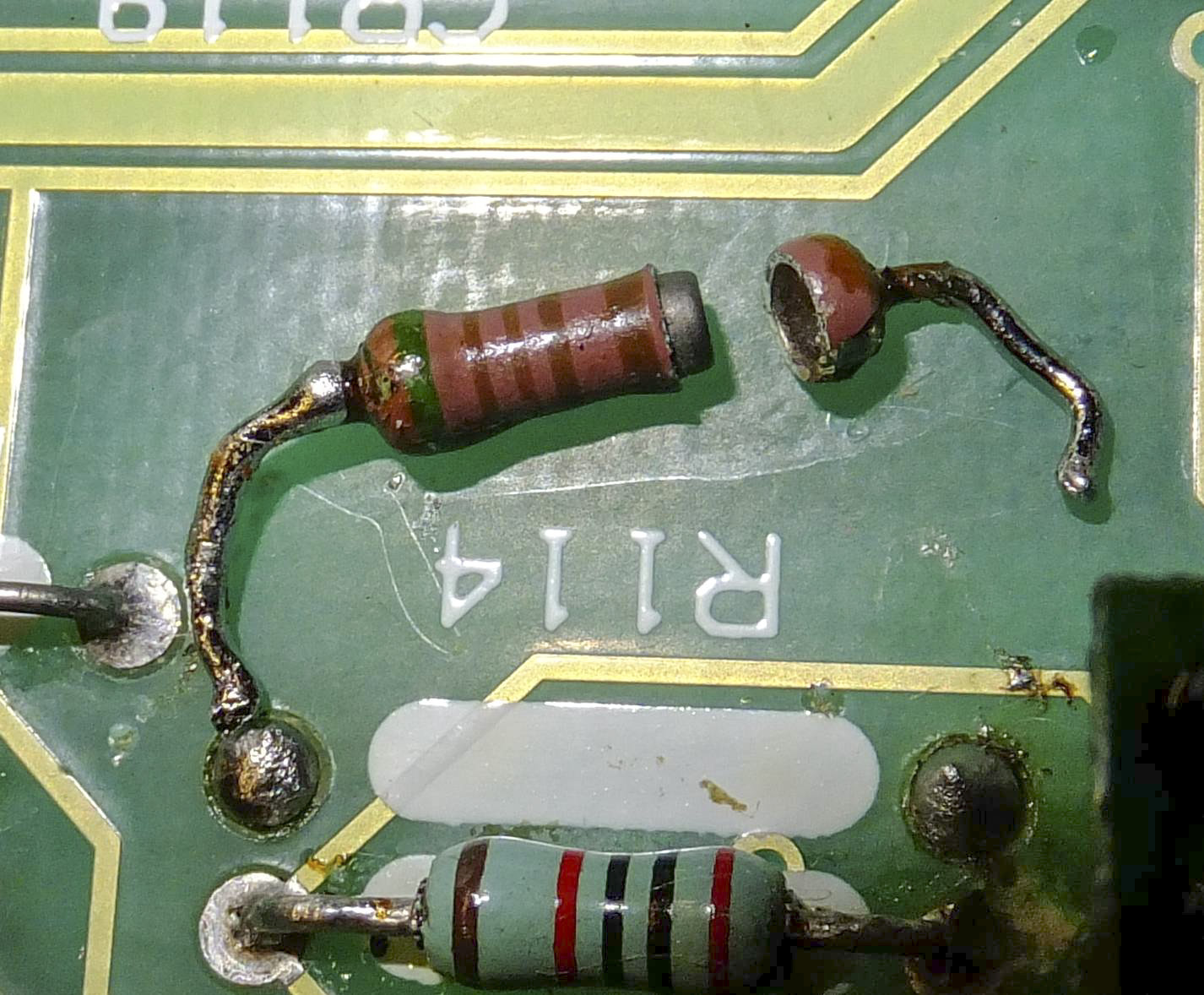
Image 36: HP 3457A original damaged R114 resistor
It is possible, than bad contacts and extra noise was caused by this resistor, as it’s directly related to noise performance of the amplifier circuitry. I’ve used foil resistors S5-61 10.4 kΩ as replacement, with very close but opposite by polarity resistance temperature coefficients:
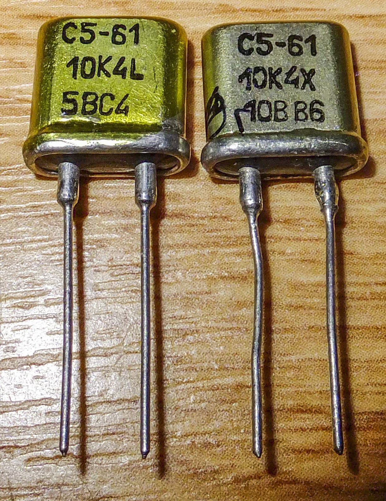
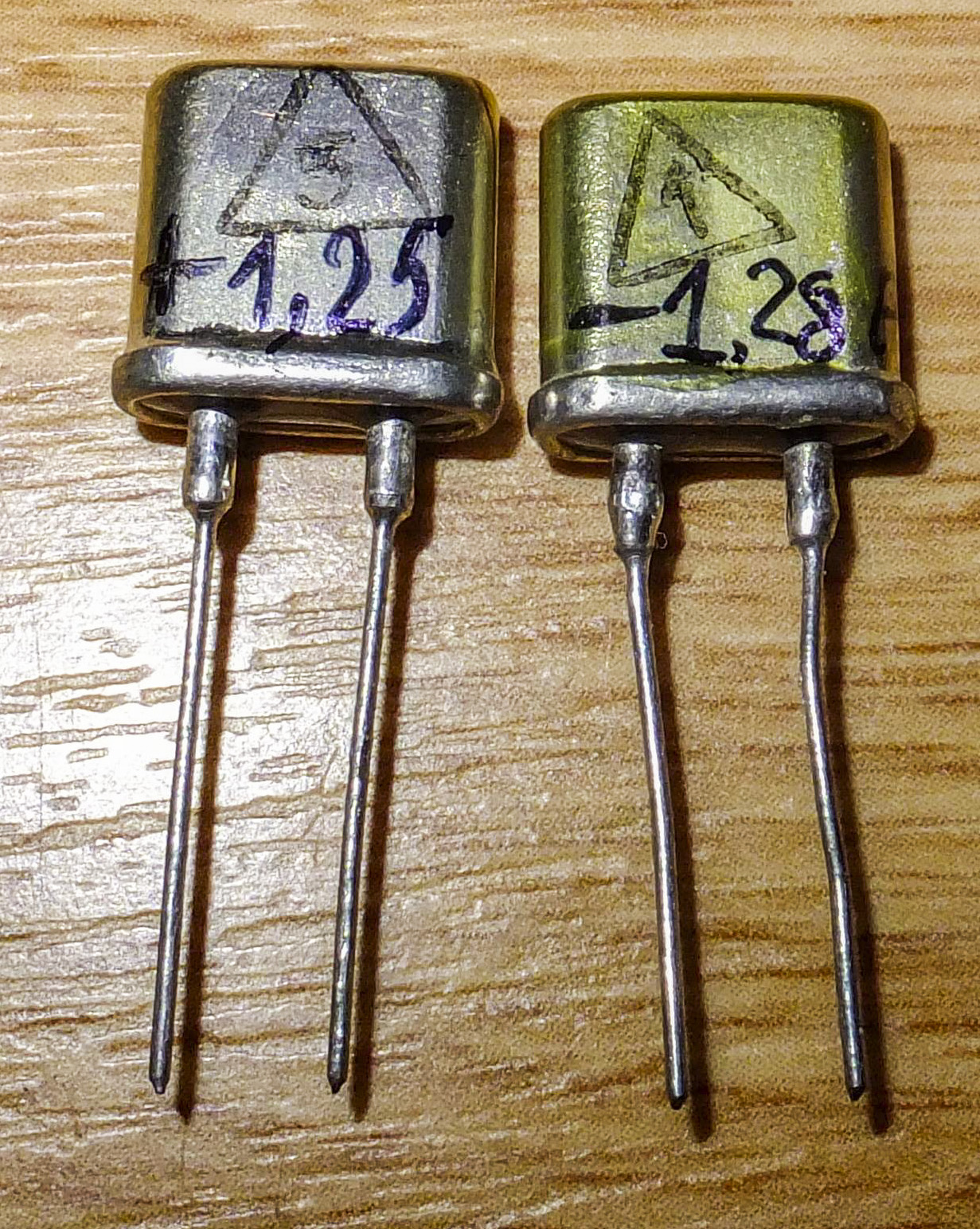
Image 37-38: Replacement foil resistors S5-61
After Q111 replacement (with faster curve than original) and U111 (more gain) input amplifier circuitry started to oscillate with frequency around 150 kHz. To get it all stable again I’ve used mica capacitors:
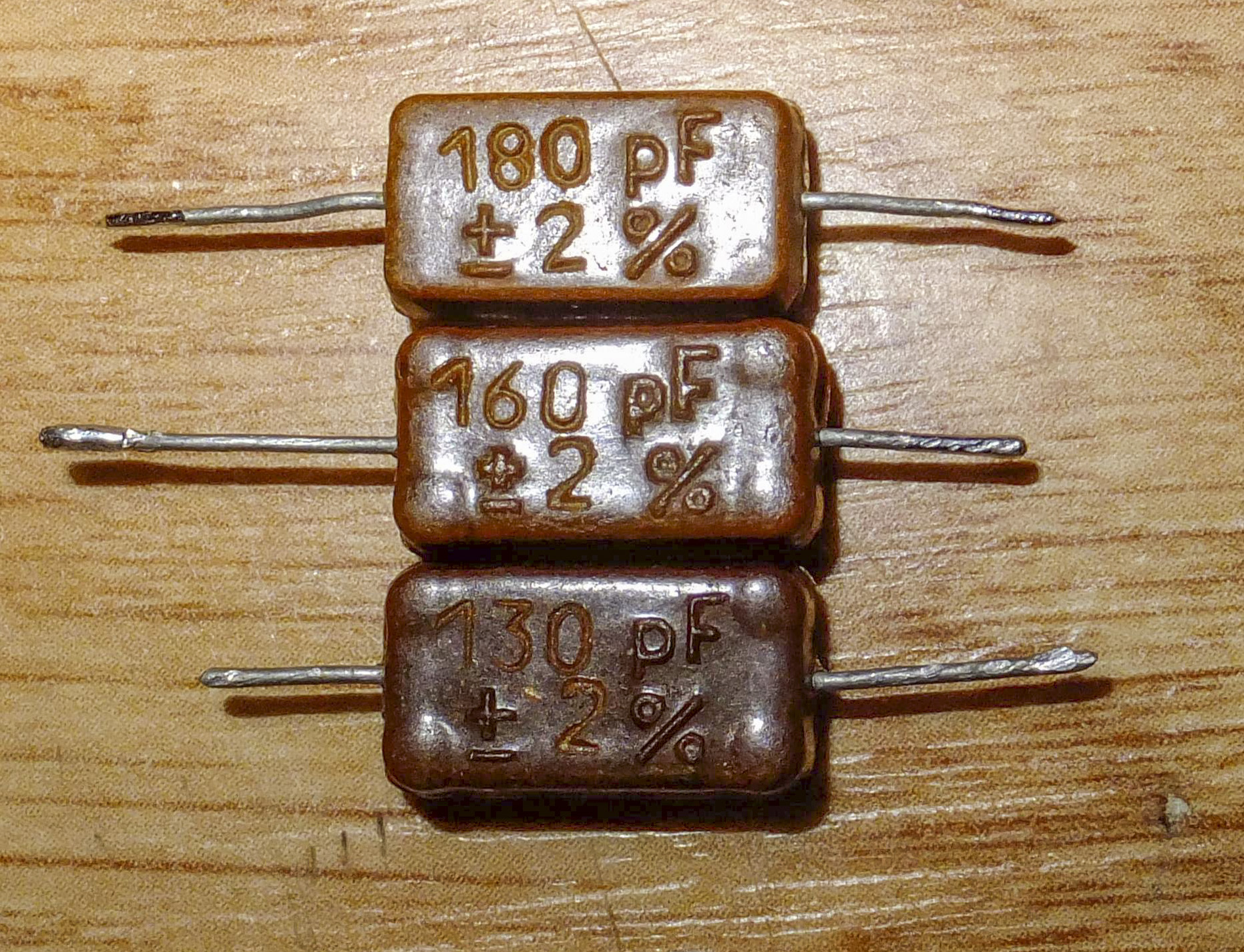
Image 39: Capacitors used for stability compensation
I used middle sweet spot device for replacement Q111. Key importance at this stage to probe output with oscilloscope, to ensure stable operation without any oscillation, with actual DC signal applied on the input, from zero all the way to the full scale 3 V. If there is lack of compensation, then amplifier will work normally when input voltage is zero or less then 0.1 V, but will oscillate in sync with auto-zero operation with larger signal amplitudes.
It was the most troublesome, to pick and sort Q111 FET replacement. I’ve bought few 2SK30A, and each FET was characterized for I/V performance. I’ve used functional generator (U3), voltmeter (U4) with GPIB, two multimeters in current measurement mode (U1 and U2) with USB interface, PC and custom test jig. Usually testing for such done using SMUs or curve tracers, but I’ve got my setup working with what I had available:
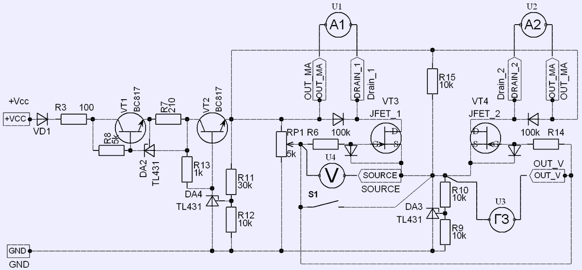
Image 40: DIY voltage-current curve plot detector
Detail description – VT1 + DA2 is current limiting for 12 mA, VT2 + DA4 is voltage regulator to provide 10 V, DA3 is middle point generator at +5 V level from power ground return. This was required to enable trimpot RP1 setting for both negative and positive gate voltage. When test jig controlled remotely by PC position of RP1 is in middle.
R6 and R14 with their protection diodes prevent gates from excessive current. Diodes in drain circuits create virtual gaps to allow current tapping by DMMs. Fixture to accept DUT FET was implemented using collet socket for 5 positions. For original dual-FET from HP 3457A I made custom adapter due to difference in pinout.
As result I can get two curves, to enable testing pair of 2SK30A’s at once. Final test data rainbow with all tested FETs:
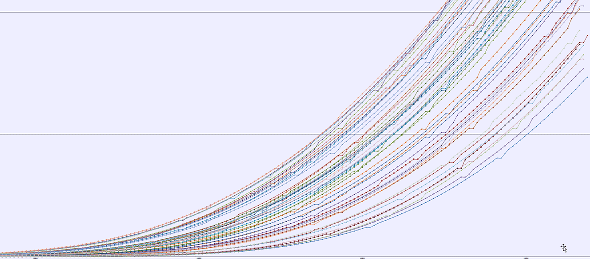
Image 41: Test data generated from many 2SK30A FETs
Original HP 3457A FET shows curve close to ideal:

Image 42: HP 3457A original Q111 matching
Our matched FET pair isn’t bad either:

Image 43: Replacement Q111 matching
One kind person (my kind regards) presented me with thin copper foil with adhesive layer. So I taped both FETs using the copper foil tape, to ensure good thermal contact between both FETs. Make sure total height of the component in board is not taller then 12 mm, as there is AC module PCBA above the circuitry here.
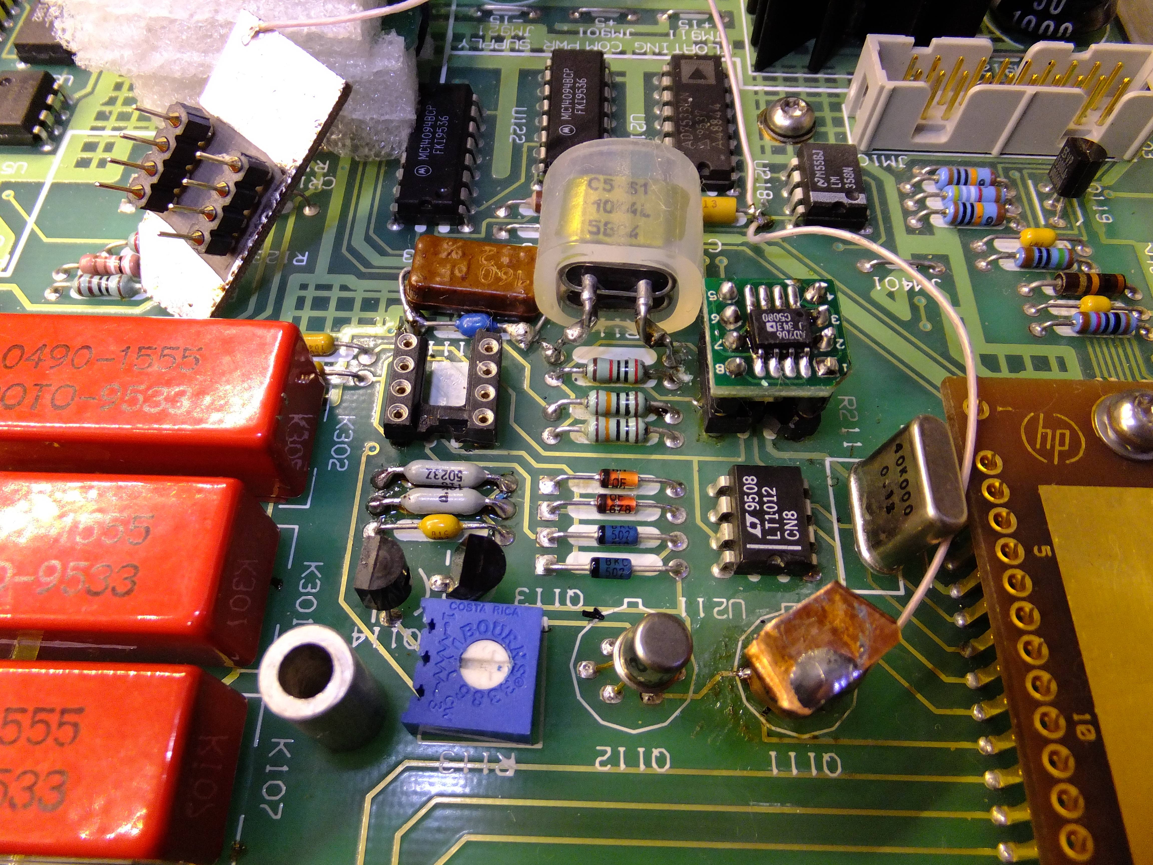
Image 44: HP 3457A input amplifier after all modifications
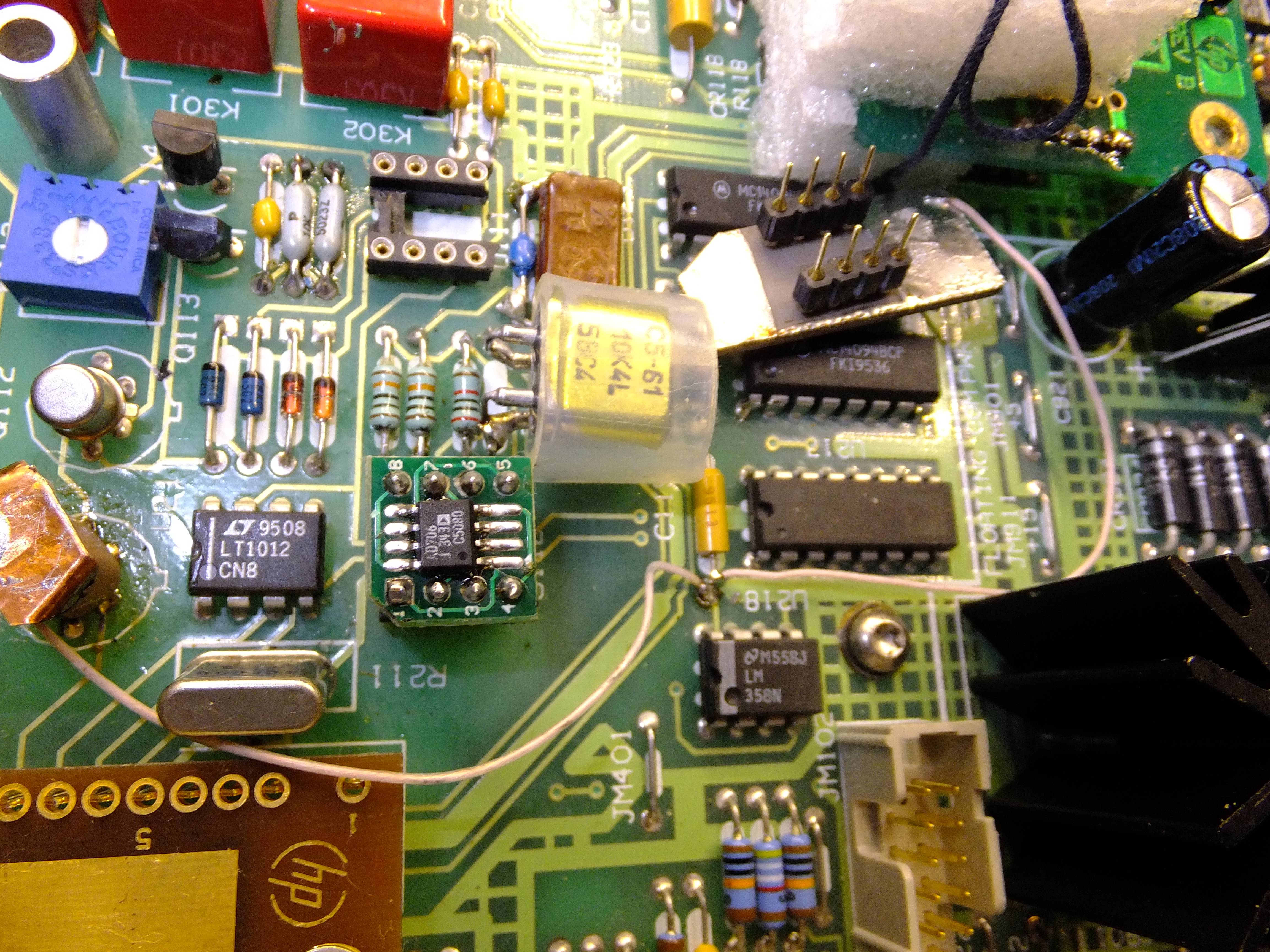

Image 45-46: Input amplifier overview
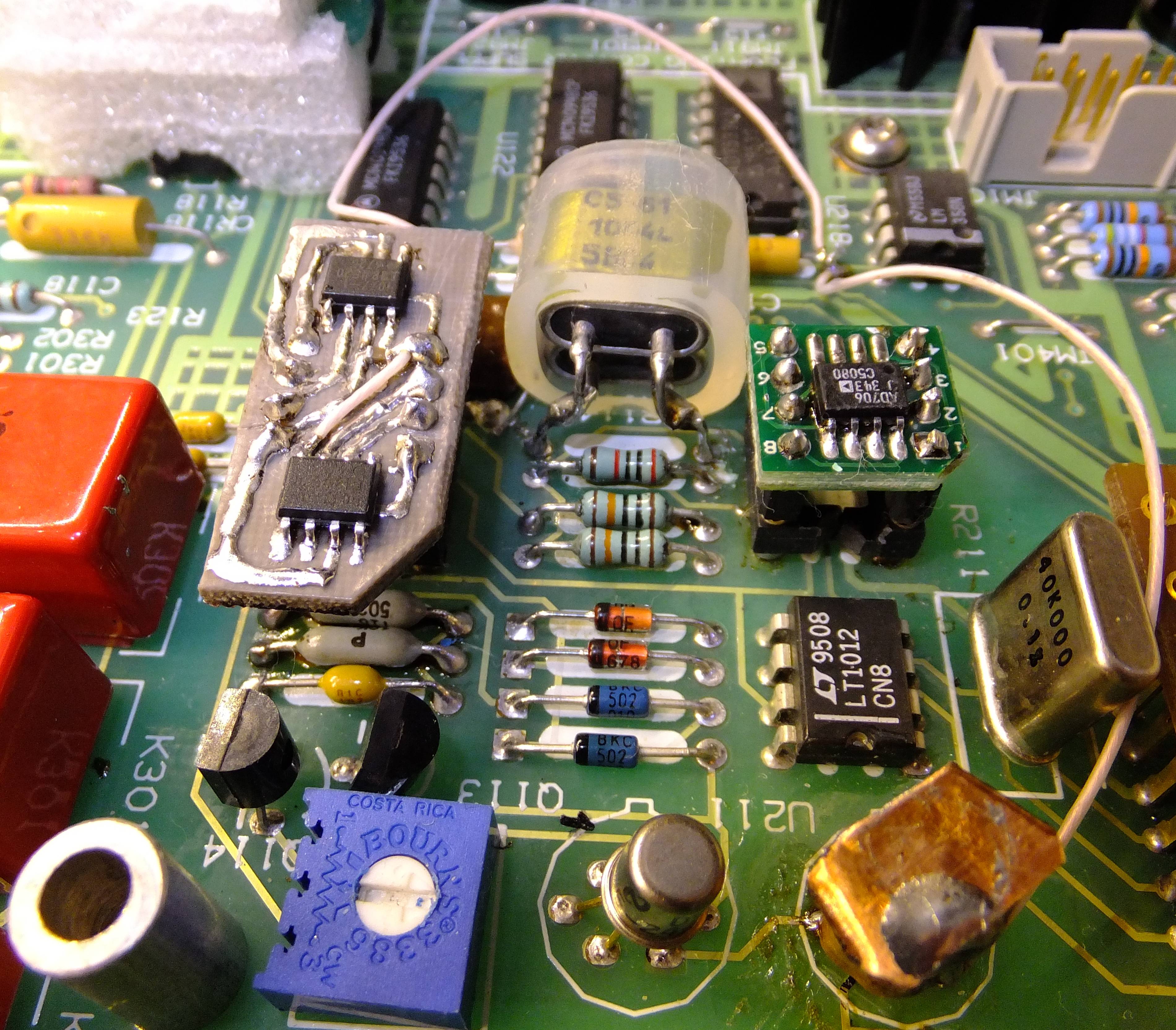
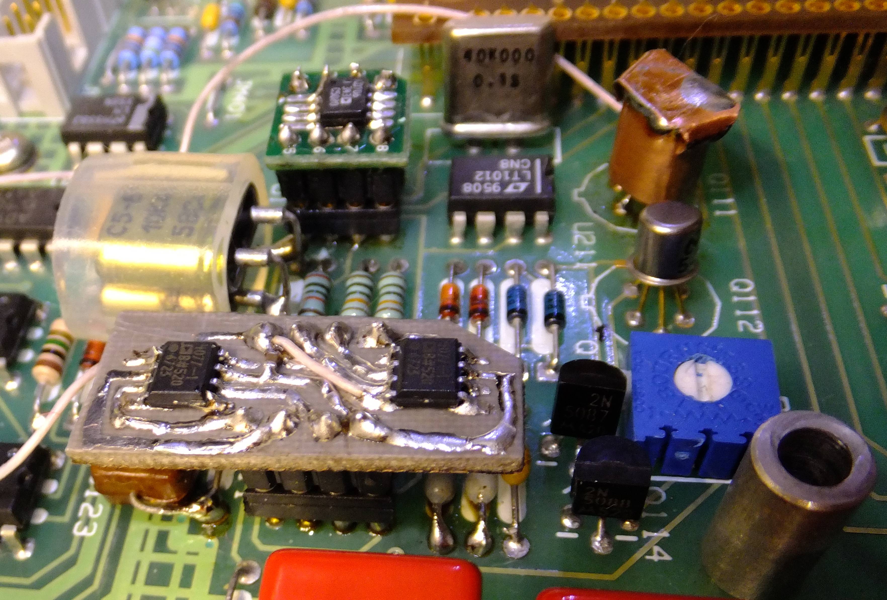
Image 47-48: Input amplifier ready for testing
Before and after condition measurement data results
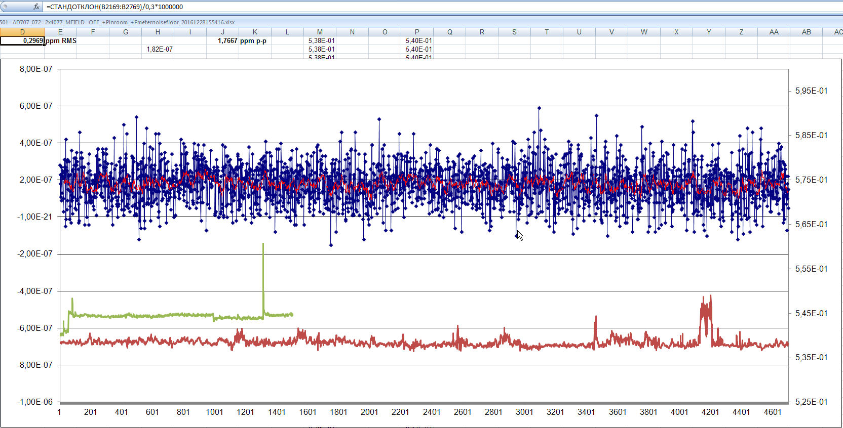
For results testing I’ve used 7½-digit measurements with shorted and thermally PE-insulated inputs. Sampling rate was equal to 0.5 Hz, getting reading every 2 seconds. Best-case “optimistic” data in 10 minute time length was selected from captured data. So we get 600 samples, where each point processed from sum of 6½-digit reading and 7th digit adder. RMS deviation was calculated, in ppm scale from the average. To measure ADC’s noise (line ADC only) JM101 jumper was desoldered and test points TP5 and TP2 were shorted together.

Image 49: Input amplifier ready for testing
Meter was connected to PC over GPIB interface to capture data over time periods.
| HP 3457A scale | Original condition, ppm RMS | After modifications, ppm RMS |
|---|---|---|
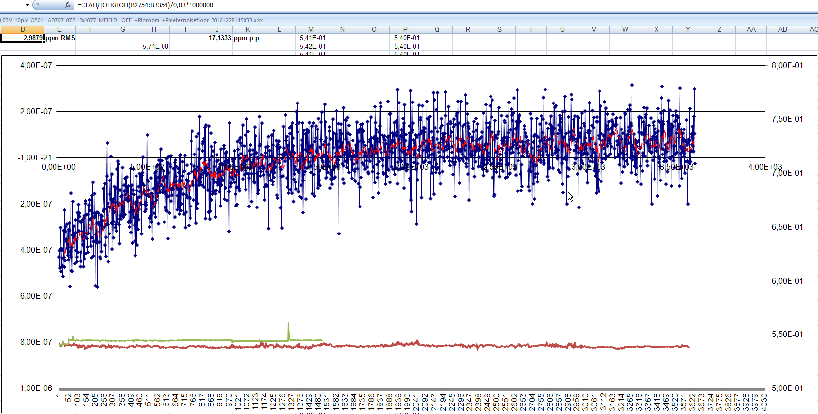
| 0.03V | 5.0525 | 2.9879 |
| 0.3V | 0.4851 | 0.2969 |
| 3V | 0.1137 | 0.0783 |
| 30V | 0.3625 | 0.3206 |
| 300V | 0.0896 | 0.0824 |
| ADC only | 0.0735 | 0.0648 |
| ADC only + cap (4.7 µF) | 1.6 | |
| ADC only + cap (0.1 µF) | 0.9 |
Table 3: RMS noise data measurements
Note, that on low voltage ranges (0.03, 0.3, 3 V) meter can pickup all the environment noise and interference, due to very high input impedance. Also ambient temperature, humidity and pressure variations affect the stability and noise performance of the meter as well.
As you can see, modifications can help to get quieter readings, especially on most sensitive ranges (about 40% reduction). This is good, even though not as impressive as HP 3456A tweaking.
| Before modifications | After modifications | |
|---|---|---|
| HP 3457A, ADC noise | 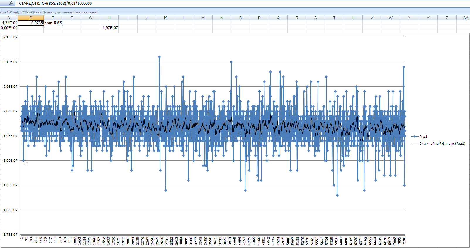 |
 |
| HP 3457A, 30 mVDC range | 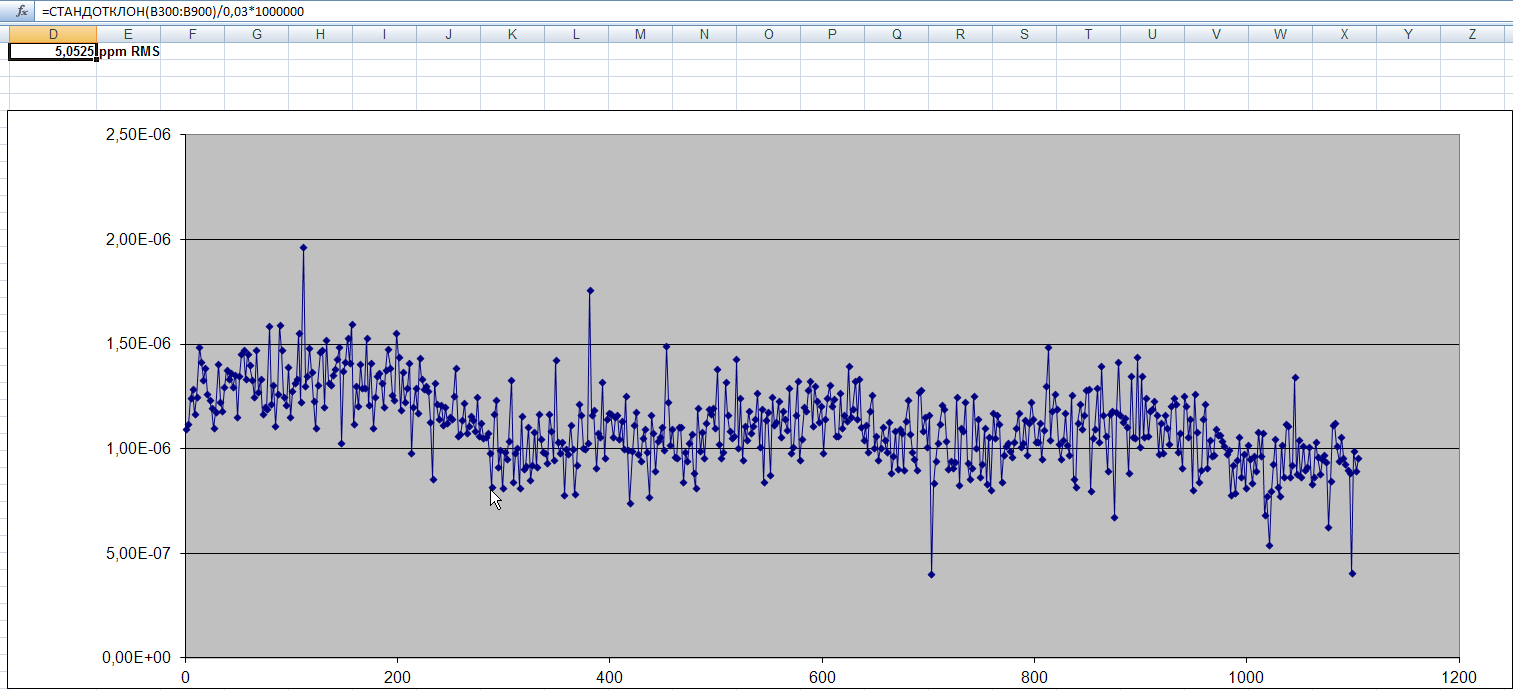 |
 |
| HP 3457A, 300 mVDC range | 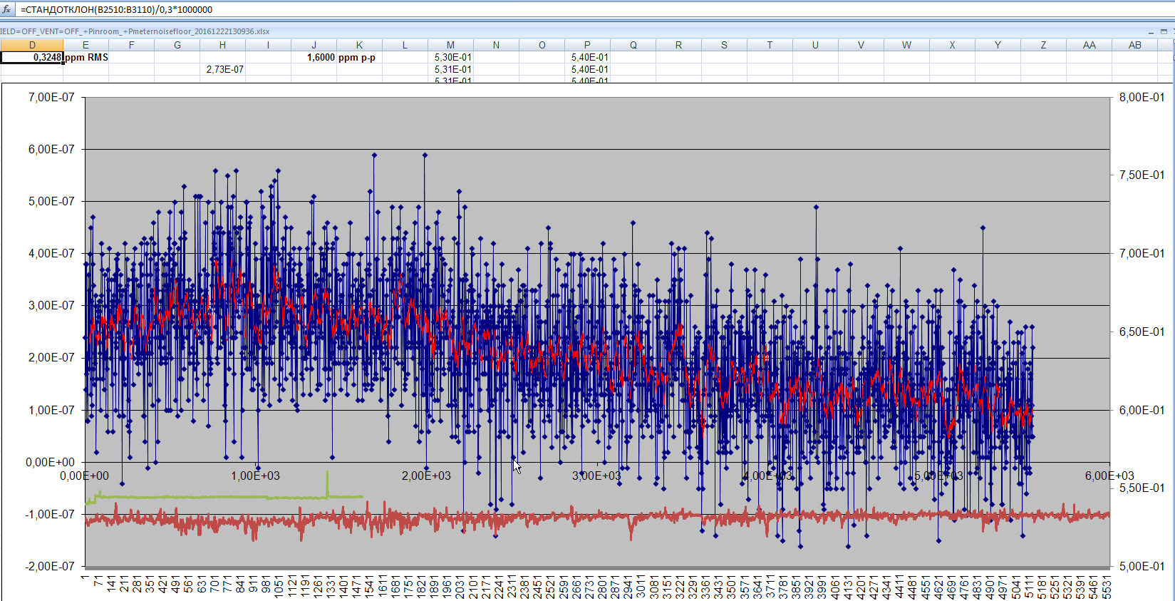 |
 |
| HP 3457A, 3 VDC range | 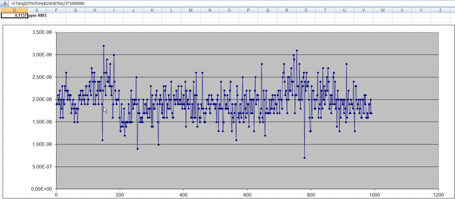 |
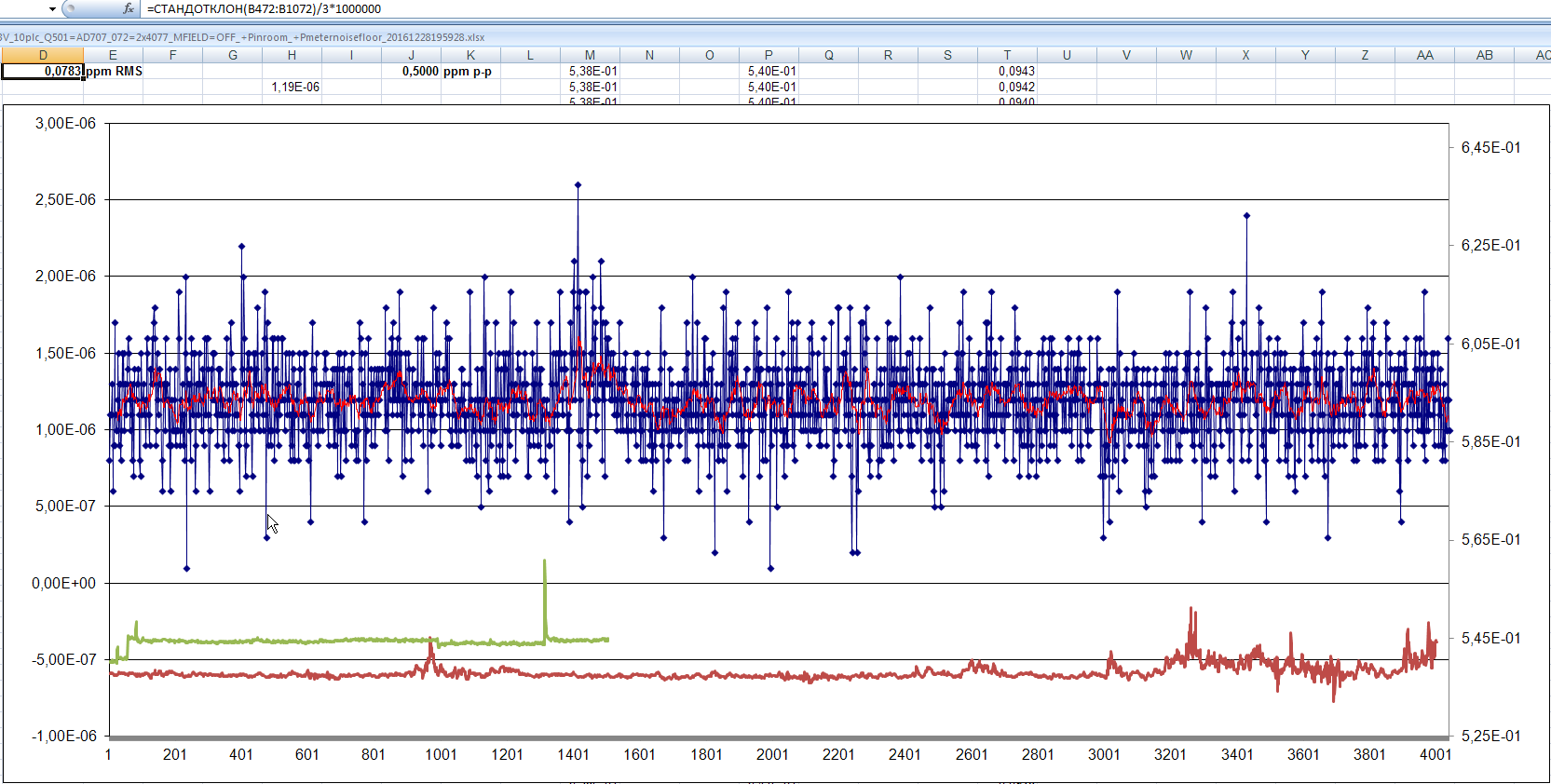 |
| HP 3457A, 30 VDC range | 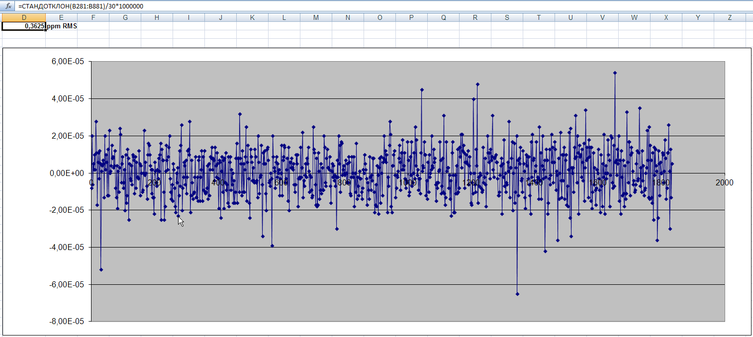 |
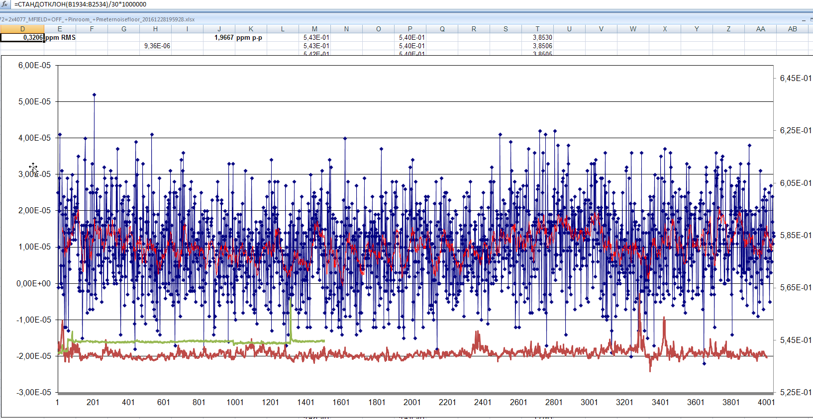 |
| HP 3457A, 300 VDC range | 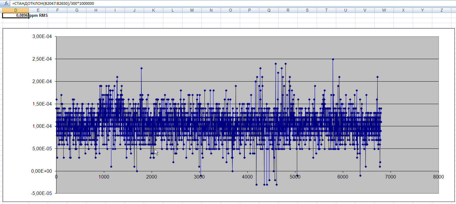 |
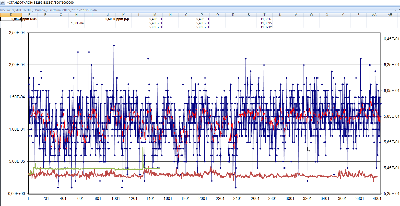 |
Table 4: Measurement noise data plots
Few practical notes about modifications
After Q111 replacement the complete input amplifier balance had to be adjusted and re-calibrated. This is little tricky. In service manual this procedure was explained for only case when self-test diagnistics related to this section unable to pass. Perhaps because of this note in service manual typical calibration in the service shops does not include this calibration either.
I had no problems with self-test, as I had calibrated the balance during initial repairs and troubleshooting in meter, before any modifications. Experimentally, I figured out that there is indeed balance offset. This also revealed that level of self-test fail threshold is ±1.5 µV, while calibration is required to level ±0.5 µV.
Calibration procedure for balancing does not adjust anything, it just shorts input amplifier input and measure if the output voltage is in spec, higher or lower than spec. This information is displayed on the screen and operator is expected to adjust R113 for best result.
So I got idea to prevent running this procedure for intermediate testing. To do so I’ve followed next workflow:
First I check if the adjustment necessary at all (why to waste time on extra drift). Press blue button, then D_AUTOZERO (display shows DELAY), then arrow down (display showss DIAGNOSTIC). Now press 4 and ENT. If PASSED is displayed, then we can exit this mode by long press of right arrow key (RESET) and not bother with anything else.
If display shows FAILED LO or FAILED HI – some work need to be done.
Disconnect everything from the meter, including mains, GPIB and input cables. Turn the meter upside down, undo 6 screws (if there are original rubber gaskets, there is no need to remove screws from cover). Now turn the meter again, front panel facing to us, remove top plastic cover and under it we can find top shield, holder of the multiplexer board.
Image 50: HP 3457A with shields installed
Those who have 3457A with multiplexer module, you’ll have to remove it. Service manual demands of removal rear terminal panel, but I have custom one in my unit, and it’s not required.
Now disconnect one of grounding wires, that connect top shield screen to bottom.
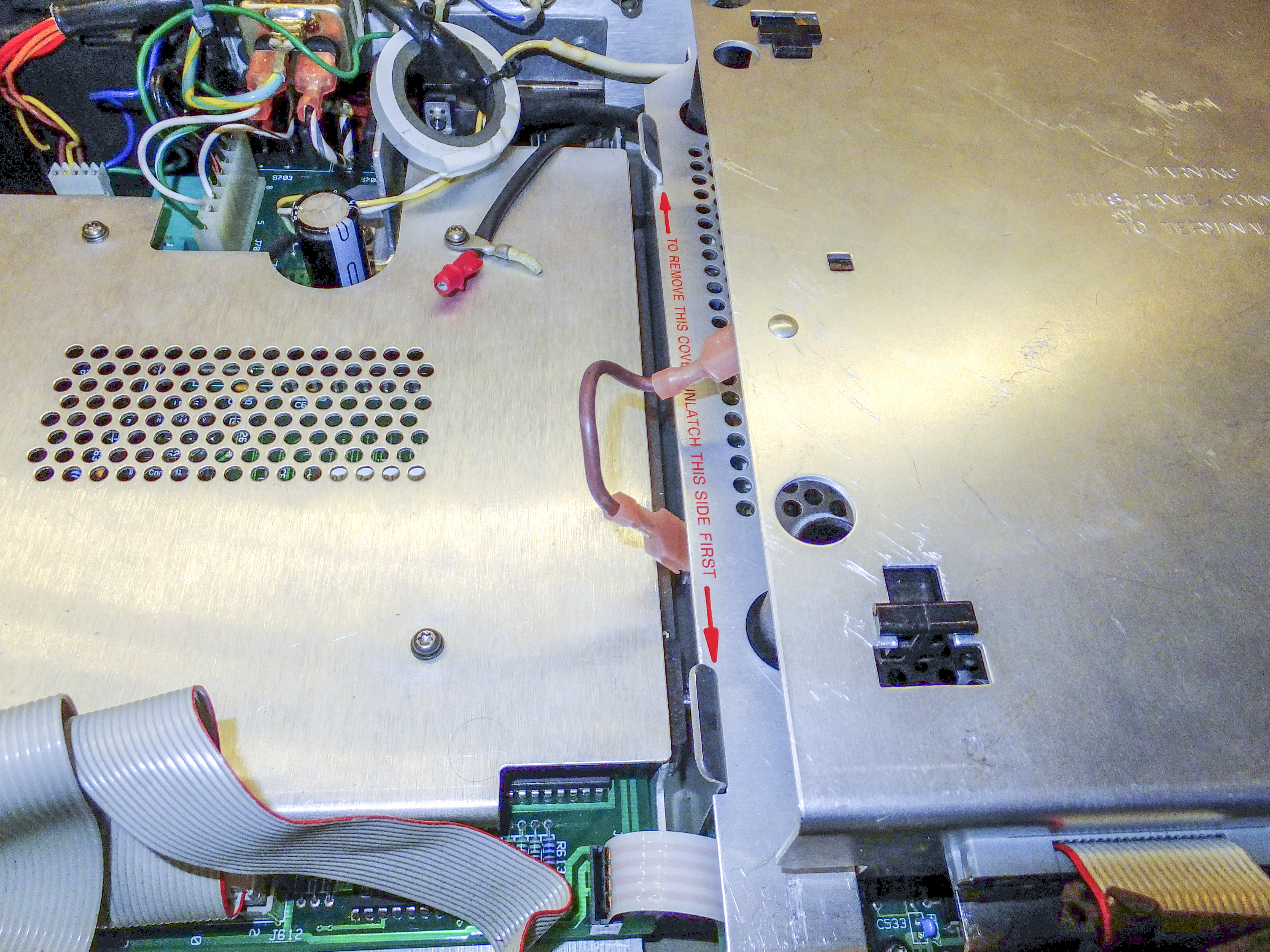
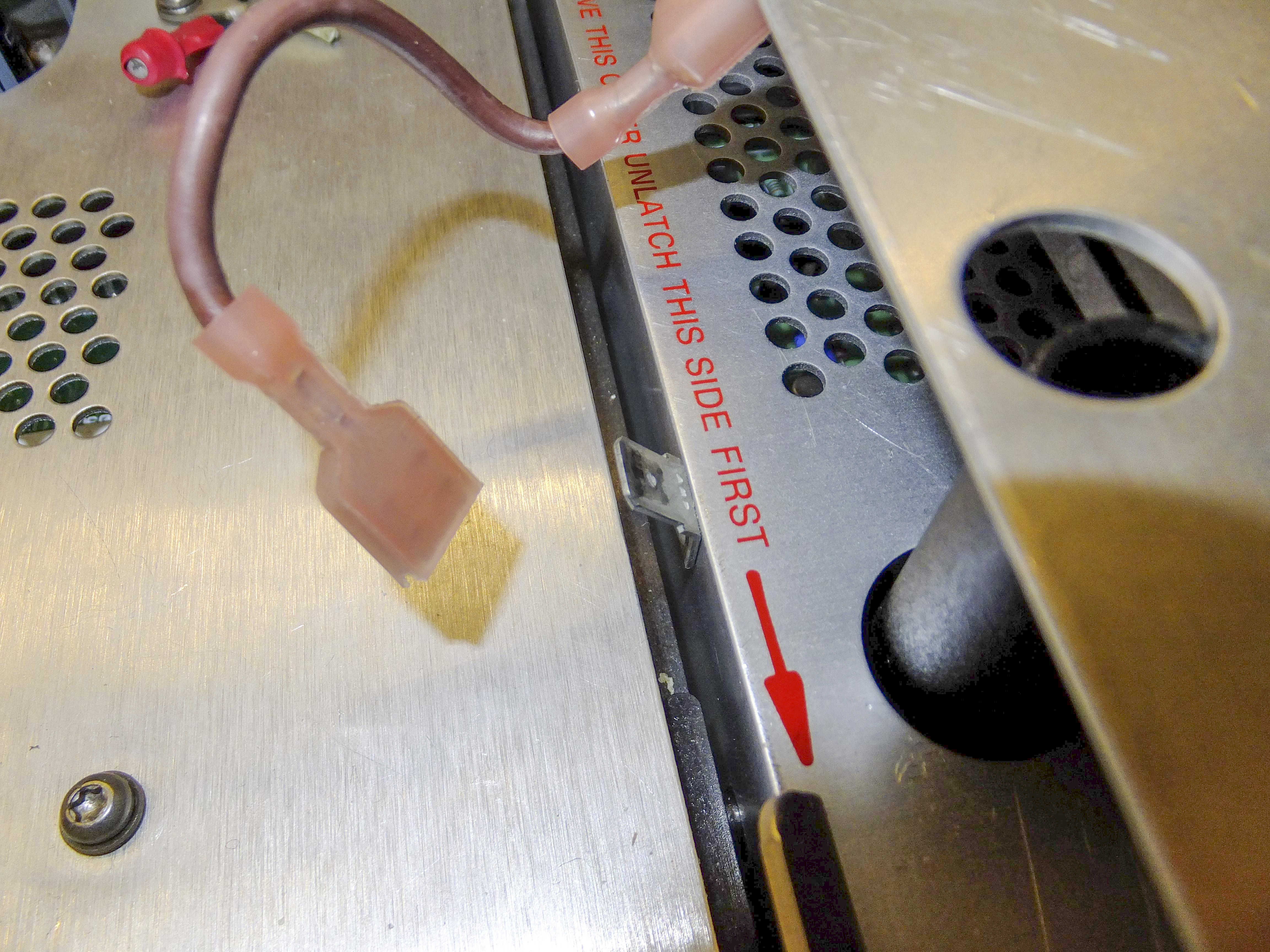
Image 51-52: Grounding wire terminal
Carefully lift rear side of the shield, disconnect cable from rear terminal and turn screen up. Now we have access to test holes, which marked as Vos Adj A2-R113. Carefully insert isolated flat screwdriver to fit the pot port.
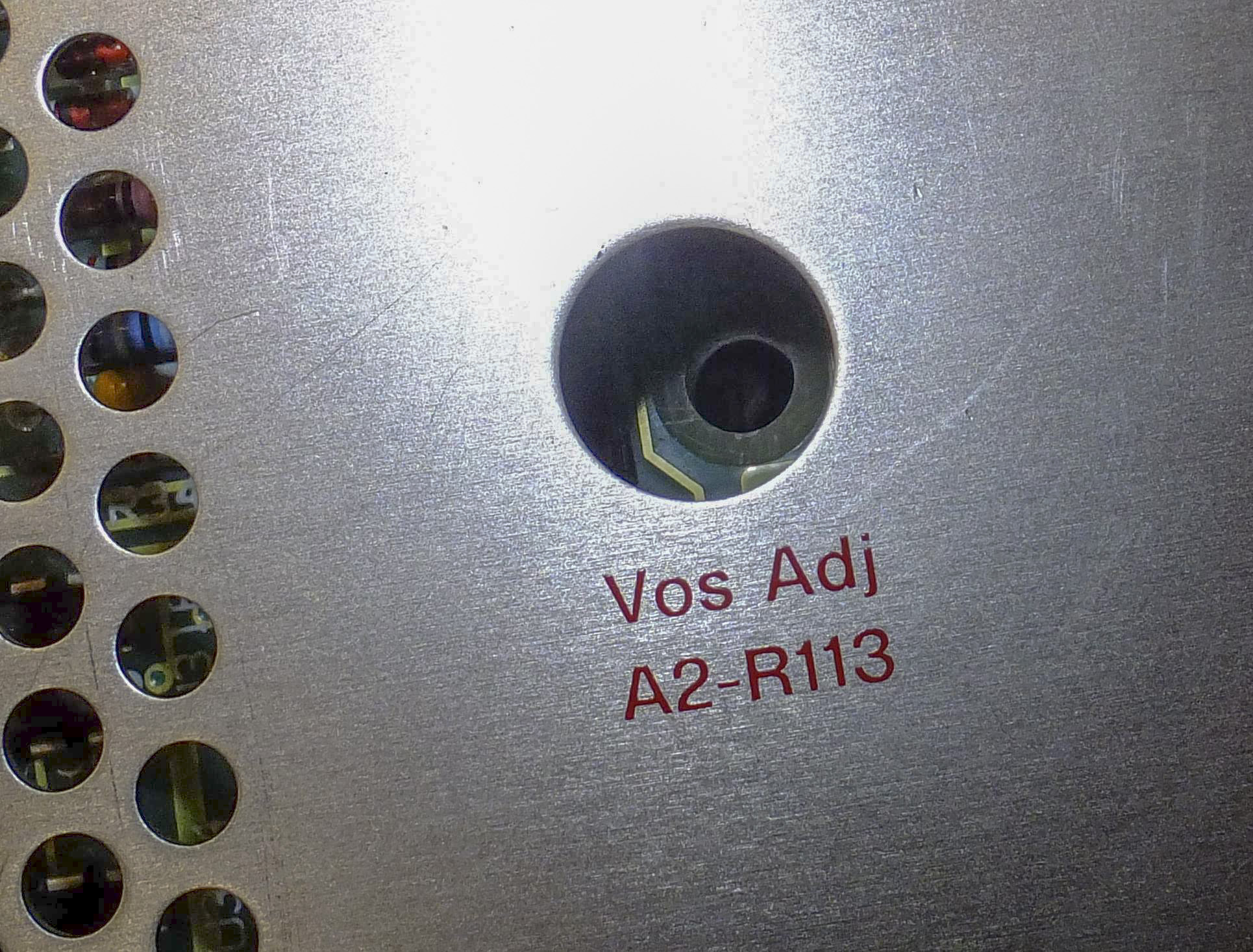
Image 53: Vos adjustment trimmer access port in shield cover
Connect mains power cable back to meter, turn it on and leave it to warm-up for at least an hour. Manual does not tell to warm-up delay, but I think it’s good idea to let things stabilize in near-use case temperatures to avoid unwanted errors. After warm-up complete, adjust the trimmer till you get PASSED result in the test as described above.
Now we can disconnect everything, assemble parts back and turn on for warming up and final tests, to make sure that meter reports still PASSED after a day or two.
Second, similar adjustment procedure should be performed in diagnostics mode 2, to correct AC frequency flatness for input divider. I had it PASSED without any issues, so I didn’t need to adjust anything. First rule of repair – do not change or fix things, that are still working fine.
If you opening the meter, it’s worth to check good connections between all binding post terminals to board headers, make sure all connections are clean and tight. Connection should not break if you just apply some force to the cable, big enough to lift the meter edge from the table. Weak contacts should be tighten carefully, but not too much. Reliability of these connections is the key for two lowest resistance ranges (30 Ω and 300 Ω).
It was common problem in other instrument (HP 3458A), reading incorrect resistances when connections were loose. If you get NEGATIVE resistance after tightening the terminals and contacts, that would mean last calibration was done with loose contacts. And calibration of that meter is very expensive, to let such mistakes pass by.
And some extra photos for bonus:

Image 54: HP 3457A input frontend and signal conditioning schematics
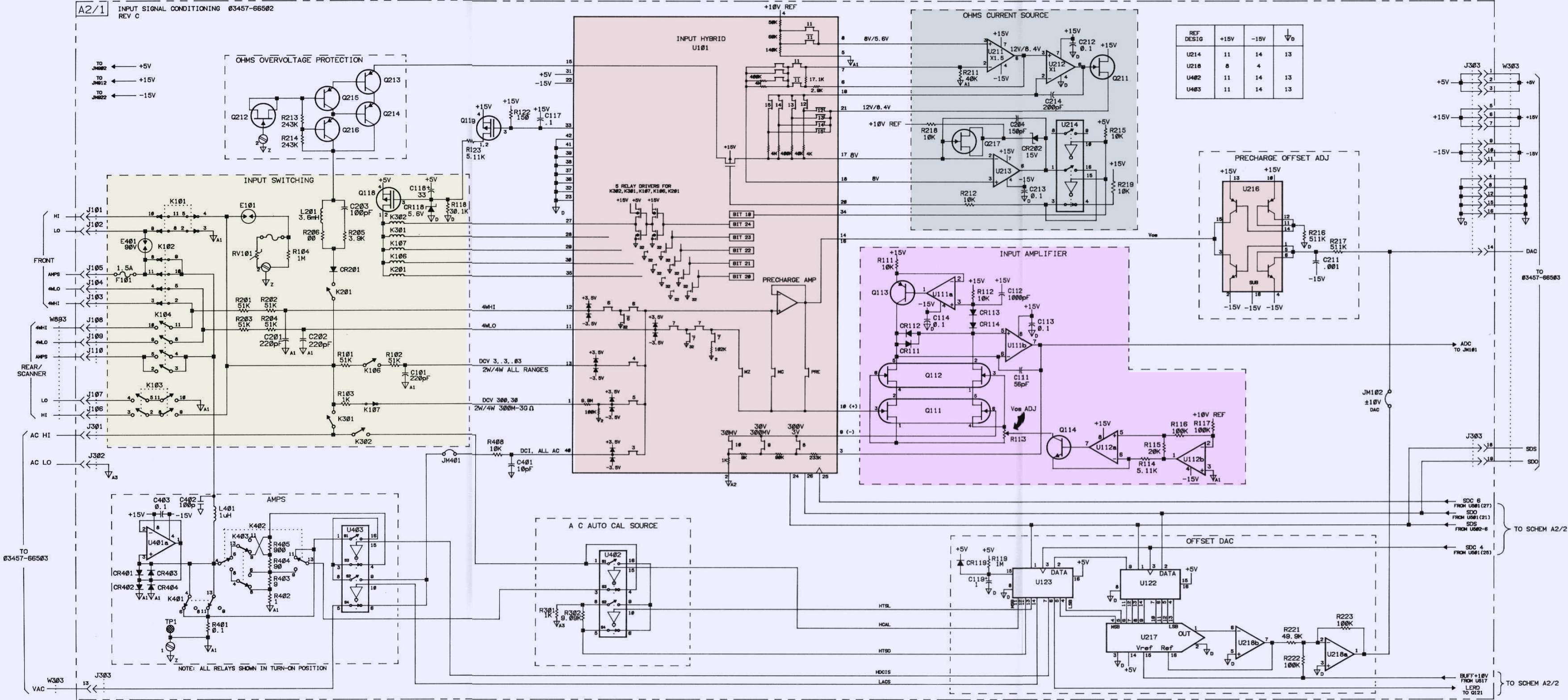
Image 55: HP 3457A A/D converter section schematics
RAMTRON memory modifications:
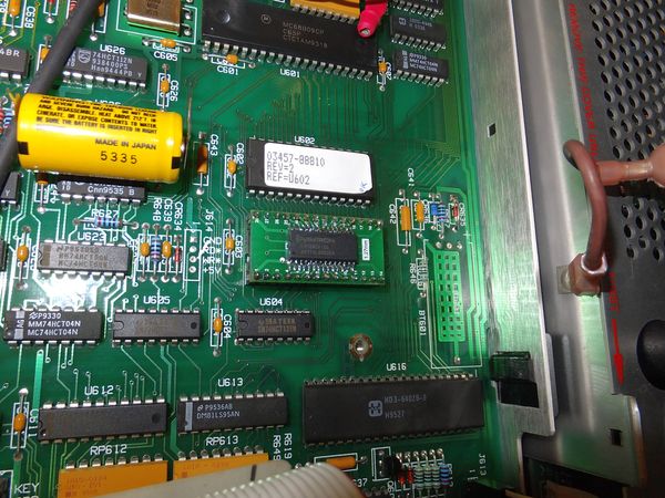
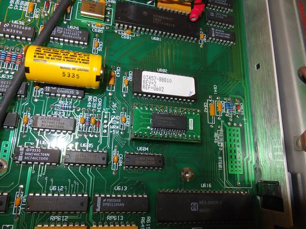
Image 56-57: Ramtron FRAM memory in HP 3457A

Image 58: Shields locked in place
Backlight modification for display
Probably all of the HP 3457A owners are “very happy” when trying to see what the heck is small LCD showing, especially in dim environment conditions. Unlike bright red LEDs on HP 3456A or fuzzy warm VFD on HP 3458A, this meter does not have ANY back-light, only passive LCD glass. Urge to attach something generating light to aid readout visibility is very hard to resist.
So I removed LED display and here’s the sad story about it:
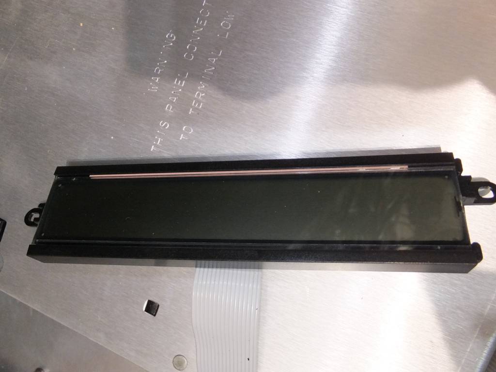
Image 59: LCD display removed from assembly
Rear side of the LCD have metal shield, which is obviously not transparent. That makes possibility of rear back-light impossible. I did not want to risk full disassembly, due to risk of killing the only working display. So I’ve decided to do my best without taking everything apart, and keeping external parts to minimum.
- External parts easy to get damaged
- Can cause unexpected short circuits, or ESD issues (running meter in winter with people wearing charged sweaters).
- Would require modification of the chassis.
So I found dead chinese cell phone in junk box, which donated six flat white SMD-LEDs. These LEDs were moved to narrow PCB:
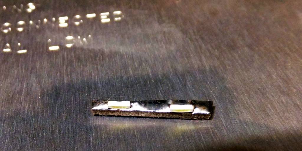
Image 60: Tiny PCB to hold LEDs in place
Backlight boards with LED diodes installed on mount frame to position light for the edge of display glass.

Image 61: LED mount for display backlight
I’ve used digital power from GPIB controller board regulator.

Image 62: LED supply power connections
Current-limiting resistors are mounted on additional board for the board with four LEDs. Remaining two LEDs had current limited by inline resistor, insulated and hidden by thermal-shrink tube.

Image 63: HP 3457A rear view on modified screen
Result at night.
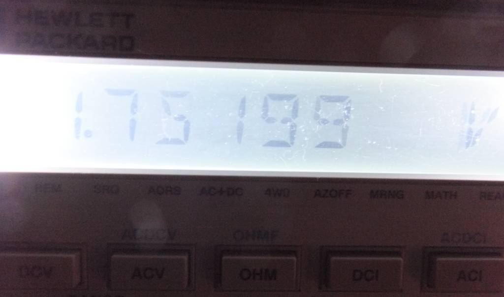
Image 64: LCD display with DIY backlight at night
In daylight.
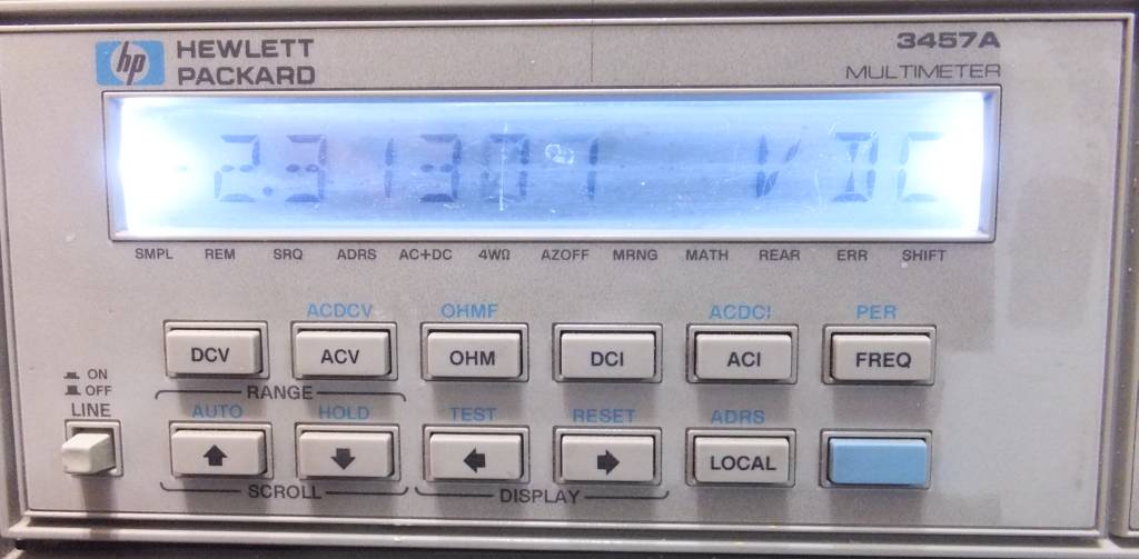
Image 65: LCD display with DIY backlight, with daylight conditions
To be fair, contrast of this LCD got bit worse, but readings are still clearly visible. Much more important fact is, that display is now visible and usable at night time.
Calibration and performance verification
This section is added by xDevs.com support team, covering calibration procedure and testing of 24-hour stability performance on DIFFERENT, non-modified HP 3457A meter. This is non-traceable calibration for education purpose only.
To run some performance numbers on HP 3457A, let’s connect one to our Fluke 5700A/03 working standard multi-function calibrator and use Python application to crunch some numbers.
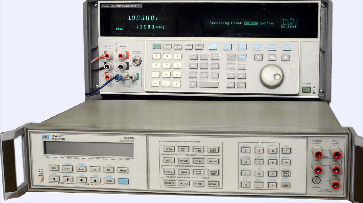
Image 66: HP 3457A 6½-digit DMM with Fluke 5700A Multi-Function Calibrator in background.
Reference source value = (Low limit + Hi limit) / 2;
Calibration CalCheck Report, generated by 5700A, January 23, 2018
DCV Function performance test
Here is automated performance verification test data before the calibration adjustment.
Before calibration adjustment, AS RECEIVED condition. Last calibration date or history of the unit is unknown.
| DCV Test | HP 3457A Data | Source uncertainty | Low Limit | Hi limit | Measured | 24hr spec | Result |
|---|---|---|---|---|---|---|---|
| 0.03 VDC (0.03 Range) | 0.0299997 | 3.81 ppm | 0.0299973 | 0.0300026 | -9.6 ppm | 83.7 ppm | PASS 11.01 % |
| -0.03 VDC (0.03 Range) | -0.0300017 | 3.81 ppm | -0.0300026 | -0.0299973 | 57.3 ppm | 83.7 ppm | PASS 65.55 % |
| 1.0 VDC (3 Range) | 1.000021 | 1.47 ppm | 0.9999933 | 1.0000066 | 21.0 ppm | 5.2 ppm | FAIL 314.84 % |
| 2.0 VDC (3 Range) | 2.000042 | 1.47 ppm | 1.9999866 | 2.0000133 | 21.0 ppm | 5.2 ppm | FAIL 314.84 % |
| 3.0 VDC (3 Range) | 3.000063 | 1.47 ppm | 2.9999799 | 3.0000200 | 21.0 ppm | 5.2 ppm | FAIL 314.84 % |
| -1.0 VDC (3 Range) | -1.000019 | 1.47 ppm | -1.0000066 | -0.9999933 | 19.0 ppm | 5.2 ppm | FAIL 284.86 % |
| -2.0 VDC (3 Range) | -2.000041 | 1.47 ppm | -2.0000133 | -1.9999866 | 20.5 ppm | 5.2 ppm | FAIL 307.35 % |
| -3.0 VDC (3 Range) | -3.000069 | 1.47 ppm | -3.0000200 | -2.9999799 | 23.0 ppm | 5.2 ppm | FAIL 344.83 % |
| 10 VDC (30 Range) | 10.000179 | 2.36 ppm | 9.9998814 | 10.000118 | 17.9 ppm | 9.5 ppm | FAIL 150.93 % |
| 20 VDC (30 Range) | 20.000358 | 2.36 ppm | 19.999762 | 20.000237 | 17.9 ppm | 9.5 ppm | FAIL 150.93 % |
| 30 VDC (30 Range) | 30.0005 | 2.36 ppm | 29.999644 | 30.000355 | 16.6 ppm | 9.5 ppm | FAIL 140.53 % |
| -10 VDC (30 Range) | -10.000159 | 2.36 ppm | -10.000118 | -9.999881 | 15.9 ppm | 9.5 ppm | FAIL 134.06 % |
| -20 VDC (30 Range) | -20.000358 | 2.36 ppm | -20.000237 | -19.999762 | 17.9 ppm | 9.5 ppm | FAIL 150.93 % |
| -30 VDC (30 Range) | -30.000649 | 2.36 ppm | -30.000355 | -29.999644 | 21.6 ppm | 9.5 ppm | FAIL 182.41 % |
| 100 VDC (300 Range) | 100.00119 | 2.85 ppm | 99.99638 | 100.00361 | 11.9 ppm | 33.3 ppm | PASS 32.92 % |
| 200 VDC (300 Range) | 200.00299 | 2.85 ppm | 199.99277 | 200.00723 | 14.9 ppm | 33.3 ppm | PASS 41.36 % |
| 300 VDC (300 Range) | 300.0069 | 2.85 ppm | 299.98915 | 300.01084 | 23.0 ppm | 33.3 ppm | PASS 63.62 % |
| -100 VDC (300 Range) | -100.001 | 2.85 ppm | -100.00361 | -99.99638 | 10.0 ppm | 33.3 ppm | PASS 27.66 % |
| -200 VDC (300 Range) | -200.0029 | 2.85 ppm | -200.00723 | -199.99277 | 14.5 ppm | 33.3 ppm | PASS 40.11 % |
| -300 VDC (300 Range) | -300.0072 | 2.85 ppm | -300.00724 | -299.99275 | 24.0 ppm | 33.3 ppm | PASS 99.38 % |
Table 5: Different non-modified HP 3457A performance test, as received, DCV function
As we can see, meter cannot meet it’s 24 hour specification for 3V and 30V ranges, but actually not that much off. 300 mVDC range was not tested due to bug in control code.
After calibration adjustment, AS RETURNED condition. Calibrated vs same Fluke 5700A on January 21, 2018.
Table below present measured data after calibration adjustment and performance verification. This is 48 hours of running time, to ensure that short-term stability of the meter is taken into account.
| DCV Test | HP 3457A Data | Source uncertainty | Low Limit | Hi limit | Measured | 24hr spec | Result |
|---|---|---|---|---|---|---|---|
| 0.03 VDC (0.03 Range) | 0.0300005 | 3.81 ppm | 0.0299973 | 0.0300026 | 17.8 ppm | 83.70 ppm | PASS 20.39 % |
| -0.03 VDC (0.03 Range) | -0.0300012 | 3.81 ppm | -0.0300026 | -0.0299973 | 41.9 ppm | 83.70 ppm | PASS 47.91 % |
| 0.3 VDC (0.3 Range) | 0.3000015 | 2.45 ppm | 0.2999953 | 0.3000046 | 5.2 ppm | 13.00 ppm | PASS 34.09 % |
| 0.2 VDC (0.3 Range) | 0.2000013 | 2.45 ppm | 0.1999969 | 0.2000030 | 6.8 ppm | 13.00 ppm | PASS 44.34 % |
| 0.1 VDC (0.3 Range) | 0.1000010 | 2.45 ppm | 0.0999984 | 0.1000015 | 9.9 ppm | 13.00 ppm | PASS 64.51 % |
| -0.1 VDC (0.3 Range) | -0.0999998 | 2.45 ppm | -0.1000015 | -0.0999984 | -1.3 ppm | 13.00 ppm | PASS 8.44 % |
| -0.2 VDC (0.3 Range) | -0.2000003 | 2.45 ppm | -0.2000030 | -0.1999969 | 1.7 ppm | 13.00 ppm | PASS 11.54 % |
| -0.3 VDC (0.3 Range) | -0.3000014 | 2.45 ppm | -0.3000046 | -0.2999953 | 4.7 ppm | 13.00 ppm | PASS 30.85 % |
| 1.0 VDC (3 Range) | 1.000003 | 1.47 ppm | 0.9999933 | 1.0000066 | 3.4 ppm | 5.20 ppm | PASS 50.97 % |
| 2.0 VDC (3 Range) | 2.000004 | 1.47 ppm | 1.9999866 | 2.0000133 | 2.2 ppm | 5.20 ppm | PASS 34.23 % |
| 3.0 VDC (3 Range) | 3.000007 | 1.47 ppm | 2.9999799 | 3.0000200 | 2.4 ppm | 5.20 ppm | PASS 36.65 % |
| -1.0 VDC (3 Range) | -0.999997 | 1.47 ppm | -1.0000066 | -0.9999933 | -2.4 ppm | 5.20 ppm | PASS 37.18 % |
| -2.0 VDC (3 Range) | -1.999998 | 1.47 ppm | -2.0000133 | -1.9999866 | -0.7 ppm | 5.20 ppm | PASS 10.74 % |
| -3.0 VDC (3 Range) | -3.000004 | 1.47 ppm | -3.0000200 | -2.9999799 | 1.6 ppm | 5.20 ppm | PASS 24.49 % |
| 10 VDC (30 Range) | 10.000053 | 2.36 ppm | 9.9998814 | 10.0001186 | 5.3 ppm | 9.50 ppm | PASS 45.25 % |
| 20 VDC (30 Range) | 20.000069 | 2.36 ppm | 19.9997628 | 20.0002372 | 3.4 ppm | 9.50 ppm | PASS 29.23 % |
| 30 VDC (30 Range) | 30.000093 | 2.36 ppm | 29.9996442 | 30.0003558 | 3.1 ppm | 9.50 ppm | PASS 26.33 % |
| -10 VDC (30 Range) | -10.000005 | 2.36 ppm | -10.0001186 | -9.9998814 | 0.5 ppm | 9.50 ppm | PASS 4.53 % |
| -20 VDC (30 Range) | -20.000053 | 2.36 ppm | -20.0002372 | -19.9997628 | 2.6 ppm | 9.50 ppm | PASS 22.48 % |
| -30 VDC (30 Range) | -30.000182 | 2.36 ppm | -30.0003558 | -29.9996442 | 6.0 ppm | 9.50 ppm | PASS 51.15 % |
| 100 VDC (300 Range) | 99.999103 | 2.85 ppm | 99.996385 | 100.003615 | -8.9 ppm | 33.30 ppm | PASS 24.80 % |
| 200 VDC (300 Range) | 199.9989 | 2.85 ppm | 199.99277 | 200.00723 | -5.5 ppm | 33.30 ppm | PASS 15.21 % |
| 300 VDC (300 Range) | 300.00069 | 2.85 ppm | 299.989155 | 300.010845 | 2.3 ppm | 33.30 ppm | PASS 6.39 % |
| -100 VDC (300 Range) | -99.99869 | 2.85 ppm | -100.003615 | -99.996385 | -13.0 ppm | 33.30 ppm | PASS 36.15 % |
| -200 VDC (300 Range) | -199.99843 | 2.85 ppm | -200.00723 | -199.99277 | -7.8 ppm | 33.30 ppm | PASS 21.72 % |
| -300 VDC (300 Range) | -300.00057 | 2.85 ppm | -300.007245 | -299.992755 | 1.9 ppm | 33.30 ppm | PASS 7.96 % |
Table 6: Different non-modified HP 3457A performance test, as returned after calibration adjustment, DCV function
Calibration revealed no problems, worst deviation is +64% for +⅓ scale of the 0.3V range. Base range, which is 3.0 VDC on this meter is now better than 3 ppm relative to calibrator.
Resistance function test (4-wire with offset compensation enabled)
Before calibration adjustment, AS RECEIVED condition. Last calibration date or history of the unit is unknown.
Resistance data as received, before any adjustment:
| DCV Test | HP 3457A Data | Source uncertainty | Low Limit | Hi limit | Measured | 24hr spec | Result |
|---|---|---|---|---|---|---|---|
| 1 Ω | 0.999676 | 40.2 ppm | 0.99969222 | 0.99990257 | -120.7 ppm | 65 ppm | FAIL 114.79 % |
| 1.9 Ω | 1.899333 | 8.3 ppm | 1.89938396 | 1.89966243 | -99.9 ppm | 65 ppm | FAIL 136.36 % |
| 10 Ω | 9.999936 | 8.3 ppm | 9.99917100 | 10.0006369 | 3.2 ppm | 65 ppm | PASS 4.46 % |
| 19 Ω | 18.99904 | 4.3 ppm | 18.9977783 | 19.0004116 | -2.8 ppm | 65 ppm | PASS 4.18 % |
| 100 Ω | 100.00203 | 4.3 ppm | 99.9977999 | 100.005460 | 4.0 ppm | 34 ppm | PASS 10.53 % |
| 190 Ω | 189.99533 | 3.3 ppm | 189.987913 | 190.002086 | 1.7 ppm | 34 ppm | PASS 4.70 % |
| 1.0 kΩ | 1000.003 | 3.3 ppm | 999.952200 | 1000.0288 | 12.5 ppm | 35 ppm | PASS 32.64 % |
| 1.9 kΩ | 1900.0177 | 3.3 ppm | 1899.92333 | 1900.06887 | 11.3 ppm | 35 ppm | PASS 29.64 % |
| 10 kΩ | 10000.1 | 3.3 ppm | 9999.68499 | 10000.451 | 3.2 ppm | 35 ppm | PASS 8.36 % |
| 19 kΩ | 18999.74 | 3.3 ppm | 18998.9573 | 19000.4126 | 2.8 ppm | 35 ppm | PASS 7.56 % |
| 100 kΩ | 100002.17 | 3.3 ppm | 99996.8799 | 100005.540 | 9.5 ppm | 40 ppm | PASS 22.09 % |
| 190 kΩ | 189994.63 | 5.3 ppm | 189984.113 | 190001.326 | 10.0 ppm | 40 ppm | PASS 22.23 % |
| 1.0 MΩ | 999992.33 | 5.3 ppm | 999949.6 | 1000050.2 | -7.5 ppm | 45 ppm | PASS 15.04 % |
| 1.9 MΩ | 1899942.7 | 14.3 ppm | 1899842.63 | 1900067.96 | -6.6 ppm | 45 ppm | PASS 11.21 % |
| 10 MΩ | 9999620 | 14.3 ppm | 9996723.16 | 10002008.8 | 25.4 ppm | 250 ppm | PASS 9.61 % |
| 19 MΩ | 18999773 | 60.3 ppm | 18993129.6 | 19004920.4 | 39.3 ppm | 250 ppm | PASS 12.69 % |
| 100 MΩ | 100423000 | 60.3 ppm | 99842216 | 100174303 | 4147.0 ppm | 1600 ppm | FAIL 249.78 % |
Table 7: Different non-modified HP 3457A performance test, as received, 4-wire resistance function
After calibration adjustment, AS RETURNED condition. Calibrated vs same Fluke 5700A on January 21, 2018.
After adjustment and calibration to ⅔ of the full-scale (example is 19 kΩ instead of 30 kΩ, as Fluke 5700A cannot provide arbitrary values).
| DCV Test | HP 3457A Data | Source uncertainty | Low Limit | Hi limit | Measured | 24hr spec | Result |
|---|---|---|---|---|---|---|---|
| 1 Ω | 0.9997266 | 40.2 ppm | 0.99969222 | 0.99990257 | -70.7 ppm | 65 ppm | PASS 67.25 % |
| 1.9 Ω | 1.89947 | 8.3 ppm | 1.89938396 | 1.89966243 | -28.0 ppm | 65 ppm | PASS 38.21 % |
| 10 Ω | 9.9999833 | 8.3 ppm | 9.99917100 | 10.0006369 | 7.9 ppm | 65 ppm | PASS 10.82 % |
| 19 Ω | 18.999227 | 4.3 ppm | 18.9977783 | 19.0004116 | 6.9 ppm | 65 ppm | PASS 10.00 % |
| 100 Ω | 100.00203 | 4.3 ppm | 99.9977999 | 100.005460 | 4.0 ppm | 34 ppm | PASS 10.53 % |
| 190 Ω | 189.99547 | 3.3 ppm | 189.987913 | 190.002086 | 2.4 ppm | 34 ppm | PASS 6.58 % |
| 1.0 kΩ | 999.99433 | 3.3 ppm | 999.952200 | 1000.0288 | 3.8 ppm | 35 ppm | PASS 10.01 % |
| 1.9 kΩ | 1900.001 | 3.3 ppm | 1899.92333 | 1900.06887 | 2.5 ppm | 35 ppm | PASS 6.73 % |
| 10 kΩ | 10000.1 | 3.3 ppm | 9999.68499 | 10000.451 | 3.2 ppm | 35 ppm | PASS 8.36 % |
| 19 kΩ | 18999.74 | 3.3 ppm | 18998.9573 | 19000.4126 | 2.8 ppm | 35 ppm | PASS 7.56 % |
| 100 kΩ | 100001.6 | 3.3 ppm | 99996.8799 | 100005.540 | 3.9 ppm | 40 ppm | PASS 9.01 % |
| 190 kΩ | 189993.47 | 5.3 ppm | 189984.113 | 190001.326 | 3.9 ppm | 40 ppm | PASS 8.68 % |
| 1.0 MΩ | 1000002.3 | 5.3 ppm | 999949.6 | 1000050.2 | 2.4 ppm | 45 ppm | PASS 4.84 % |
| 1.9 MΩ | 1899962 | 14.3 ppm | 1899842.63 | 1900067.96 | 3.5 ppm | 45 ppm | PASS 5.95 % |
| 10 MΩ | 9999443.3 | 14.3 ppm | 9996723.16 | 10002008.8 | 7.7 ppm | 250 ppm | PASS 2.93 % |
| 19 MΩ | 18999373 | 60.3 ppm | 18993129.6 | 19004920.4 | 18.3 ppm | 250 ppm | PASS 5.91 % |
| 100 MΩ | 100006630 | 60.3 ppm | 99842216.2 | 100174303 | -16.2 ppm | 1600 ppm | PASS 0.98 % |
Table 8: Different non-modified HP 3457A performance test, as returned after calibration adjustment, 4-wire resistance
Test on highest range with 1 GΩ standard was not performed.
Rest of the functions like AC voltage, DC and AC currents are also verified, and both calibration reports are available in PDF below.
CQ Calibration Report, HP 3457A as received condition, January 20, 2018
CQ Calibration Report, HP 3457A as returned condition, adjusted, January 24, 2018
Note out of 24-hour specification for negative 3.00000 mADC signal. Few attempts to calibrate it out (by rerunning DCV and DCI zero calibration and +3.00000 mA FS calibration) did not succed, as this measurement remained about -100 ppm from the reference. Wondering, if that is design issue of HP 3457A, or simply particular unit trait.
Credits for this testing and calibration goes to xDevs’s frequent contributor and metrology nut Todd. Thank you! :)
Conclusion
We learned few interesting things about 6½-digit HP 3457A meter, which had some unusual design choices. Today these meters are available on secondary market for good prices, and can be interesting tool for novice analog design engineers who’d like to peek deeper into analog precision design. Cost of maintenance on these meters is reachable even for hobby users to use a lab working tool.
xDevs.com would like to apologize to author of this article, TEKTRON for very long time on this publication. We sincerely promise to do better next time.
Discussion is very welcome thru comment section or at our own IRC chat server: irc.xdevs.com (standard port 6667, channel: #xDevs.com). Web-interface for access mirrored on this page.
Projects like this are born from passion and a desire to share how things work. Education is the foundation of a healthy society - especially important in today's volatile world. xDevs began as a personal project notepad in Kherson, Ukraine back in 2008 and has grown with support of passionate readers just like you. There are no (and never will be) any ads, sponsors or shareholders behind xDevs.com, just a commitment to inspire and help learning. If you are in a position to help others like us, please consider supporting xDevs.com’s home-country Ukraine in its defense of freedom to speak, freedom to live in peace and freedom to choose their way. You can use official site to support Ukraine – United24 or Help99. Every cent counts.
Modified: Feb. 4, 2018, 5:21 p.m.