- Intro
- Disclaimer
- Manuals references, firmware dumps and service information
- HP 53131A with channel 3 input option with 3 GHz range
- Agilent 53132A Counter
- Quick look inside current Keysight 53230A and option 015
- Difference between 53131A and 53132A and possible DIY upgrade
- Some measurements and benchmarks
- Summary and conclusion
Intro
Frequency and timing counters are useful tools for electronics engineering. With xDevs.com’s main focus in the DC metrology domain, it’s not the first instrument that comes to mind for the bench, so until today there was no good low-frequency counter in the lab. Now, this shortcoming was alleviated to support with some timings and delay measurements for new in-house ADC/DAC projects.
Thanks to friendly support, I’ve got now working HP 53131A unit and broken Agilent 53132A. In this article we will take a look inside the both units, work on possible repairs and perhaps take few measurements to get overall idea of these counters performance.
Model 5313X and 53181A counters are obsoleted now and replaced by newer fancy Keysight 53200 series instruments which bring better performance, newer LCD-based UI and additional options. 53131/53132A still are very capable instruments and can be purchased on secondary used market for anything from few hundred USD up to 1k$ depending on condition, faults and included options. 53181A is cheaper two channel version of the counter. Main difference for options is for additional third port input with frequency range from 3 GHz to 12.4 GHz and various ovenized internal time base options for more precise measurements.
These half-rack sized instruments can also have a number of the options available for additional functionality:
- Option 001 – Medium stability timebase
- Option 002 – External DC power supply option, 10 to 32 VDC, 4 A inrush
- Option 010 – High stability timebase
- Option 012 – Ultra high stability timebase
- Option 015 – 1.5GHz 50 Ω Input 2 for 53181A only
- Option 030 – Input 3 with 100 MHz to 3 GHz 50 Ω BNC input frequency range, -21 dBm to +13 dBm
- Option 050 – Input 3 with 100 MHz to 5 GHz 50 Ω N type input frequency range, -27 dBm to +13 dBm
- Option 124 – Input 3 with 100 MHz to 12.4 GHz 50 Ω N type input frequency range
- Option 060 – Rear-panel connectors option
| 53131A | 53132A | 53181A | 53230A | |
|---|---|---|---|---|
| Channels | 1 to 3 | 1 to 3 | 1 to 2 | 1 to 3 |
| Input sensitivity | 20 mVRMS to ±5 VAC-DC for 50 Ω | |||
| Trigger level | ±5.125V with 5mV resolution | |||
| Gate time | 1ms to 1000s | 1 µs to 1000s | ||
| Bandwidth | 1 mHz to 225 MHz (1.5, 3, 5, 12.4 GHz opt) | 1 mHz to 350 MHz (6, 15 GHz opt) | ||
| Resolution | 10 digits/s | 12 digits/s | 10 digits/s | 12 digits/s, max 15 digits |
| Time interval resolution | 500 ps | 150 ps | 500 ps | 20 ps |
| Timebase stability | ±5 ppm (<2.5 ppb option) | ±1 ppm (<0.3 ppb option 010) | ||
| Timebase ageing | ±0.3 ppm/month (0.02 ppm/year optional) | ±0.2 ppm/month (±0.05 year option 010) | ||
| Speed | 200 measurements/sd | 75000-90000 readings/s | ||
| Interfaces | GPIB, RS-232 | USB,LXI LAN, GPIB optional | ||
| Battery power | None | Option 300 | ||
| Released price | Obsolete, no longer supported | 5932 USD | ||
Table above shows comparison of key parameters between different models, including modern replacement improved 53230A. Cheaper Keysight 53210A (3303 USD) provide performance similar to 53131A and mid-range Keysight 53220A (3814 USD) replaces 53132A.
Disclaimer
Redistribution and use of this article or any images or files referenced in it, in source and binary forms, with or without modification, are permitted provided that the following conditions are met:
- Redistributions of article must retain the above copyright notice, this list of conditions, link to this page (/fix/hp5313X/) and the following disclaimer.
- Redistributions of files in binary form must reproduce the above copyright notice, this list of conditions, link to this page (/fix/hp5313X/), and the following disclaimer in the documentation and/or other materials provided with the distribution, for example Readme file.
All information posted here is hosted just for education purposes and provided AS IS. In no event shall the author, xDevs.com site, or any other 3rd party, including HP/Agilent/Keysight be liable for any special, direct, indirect, or consequential damages or any damages whatsoever resulting from loss of use, data or profits, whether in an action of contract, negligence or other tortuous action, arising out of or in connection with the use or performance of information published here.
If you willing to contribute or add your experience regarding HP/Agilent/Keysight instruments repairs or provide extra information, you can do so following these simple instructions
Manuals references, firmware dumps and service information
Before we begin digging into hardware it is always useful to read some documentation and manuals from the manufacturer.
Datasheet for 53131A/53132A/53181A
Old HP datasheet for 53131A/53132A/53181A
53131A/53132A/53181A DS Counters.pdf
Operating guide for Agilent 53131A/53132A, P/N 53131-90055
Options matrix for 53131A/53132A/53181A and 53200 series counters
Improving HP 53131A timebase calibration
Tips for making more accurate measurements with counters
Keysight 53200 series RF frequency counters/timers
Firmware image dumps
Latest firmware for 53132A is 4806 but I don’t have this firmware dump available. If you have one, please feel free to upload to xDevs.
Software and tools
HPAK IntuiLink Software for counters, March 12 2008
Service information
HP 53131 Assembly level Service Manual
Agilent 53131A/53132A Assembly Level Service Manual, P/N 53131-90039 March 2009
HP 531XX Assembly level Service Manual
HP 53131A Component Level Repair Manual with schematics+BOM
HP 53132A Component Level Repair Manual with schematics+BOM
HP 53132A Component Level Repair Manual with schematics+BOM
HP 53132-60011 Timebase option schematics, redrawn
HP 53181A Component Level Repair Manual with schematics+BOM
There is also number of service notes/engineering changes were published during years of product lifecycle. If your unit is old, worth to check if any of them required to do:
Service Note 53132A-01 – Unit powers up in Standby mode
Service Note 53132A-03 – GPIB hangs when power for instrument is turned on at the same time as PC
Service Note 53131/53132A-08 – Video by Keysight Hands-on
HP 53131A with channel 3 input option with 3 GHz range
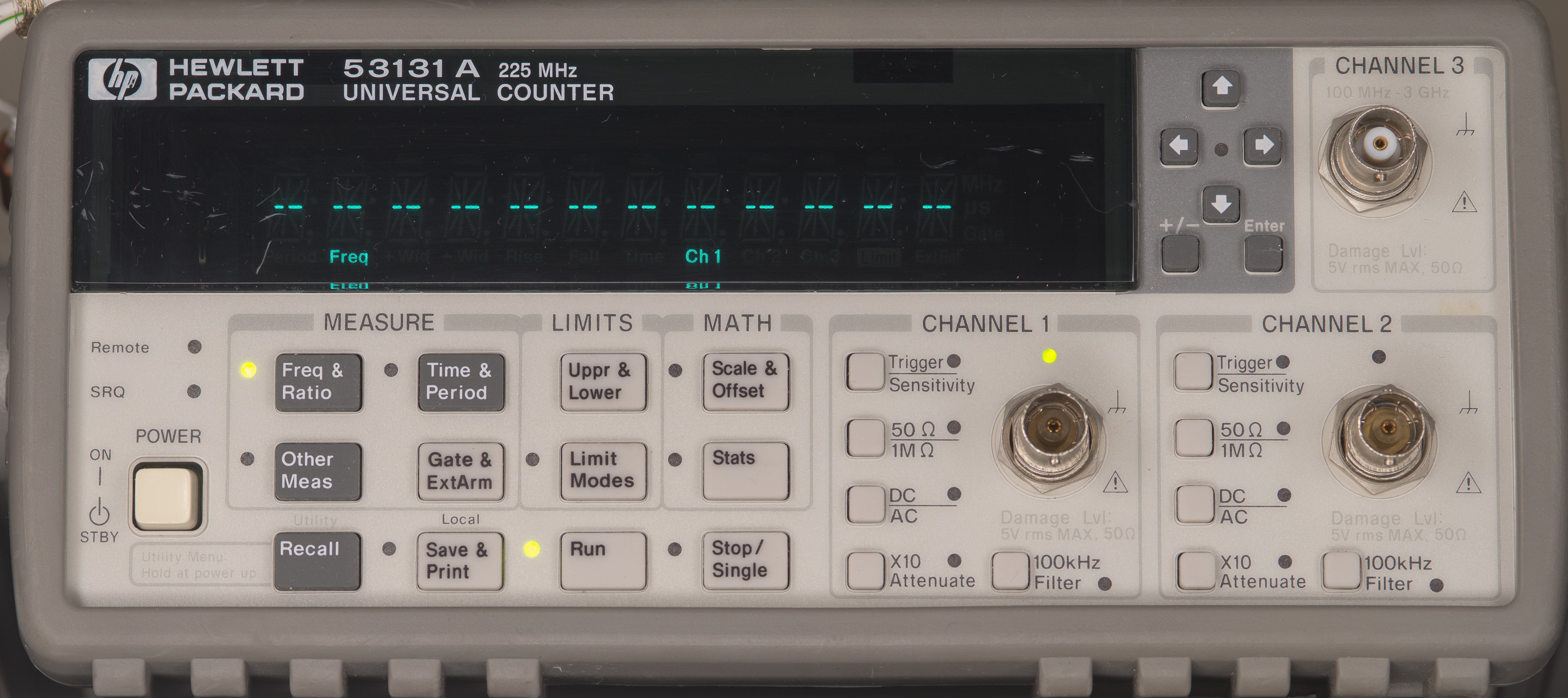
Image 1: Counter as received
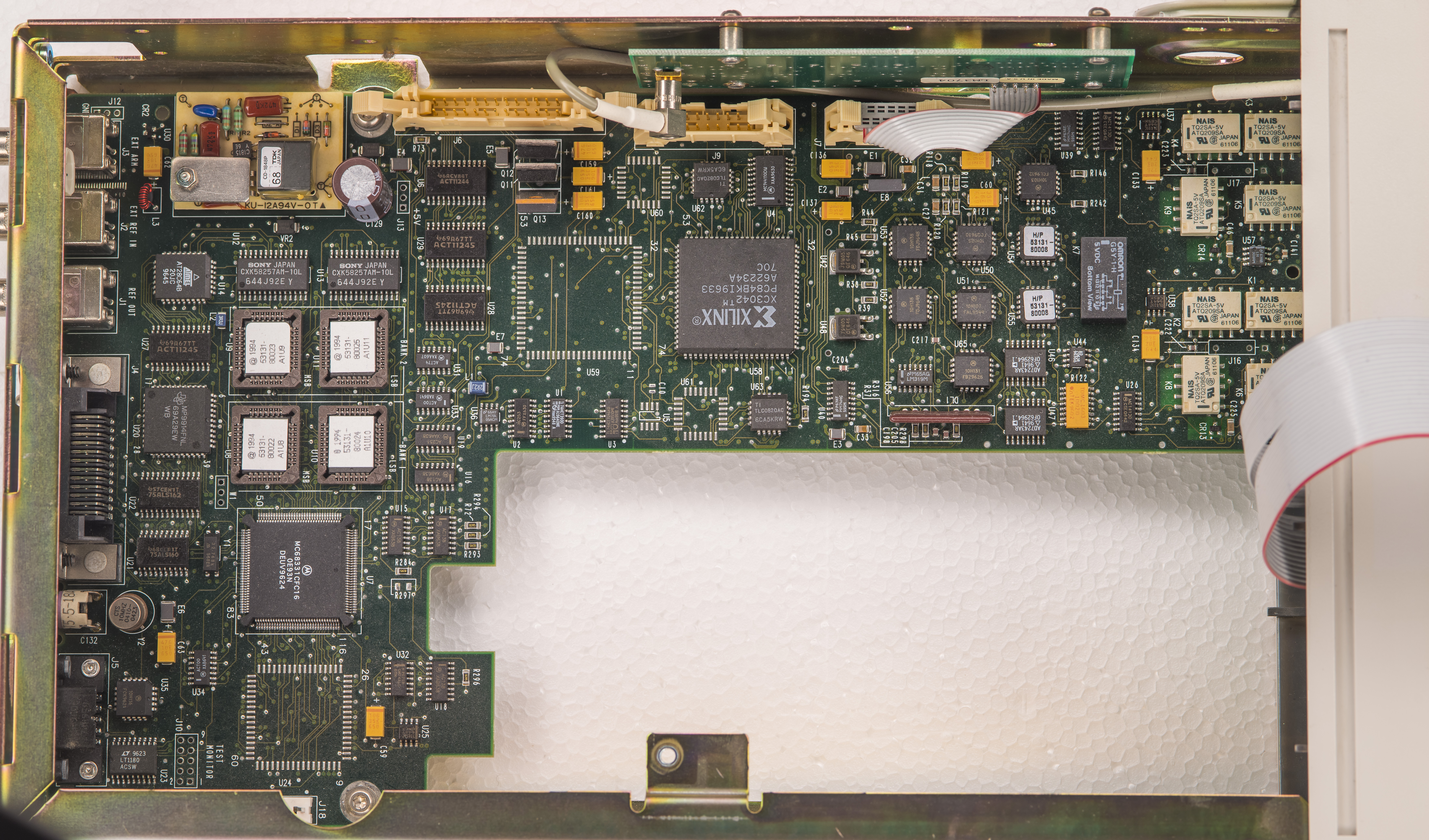
Image 2: Top side view with PSU assembly removed
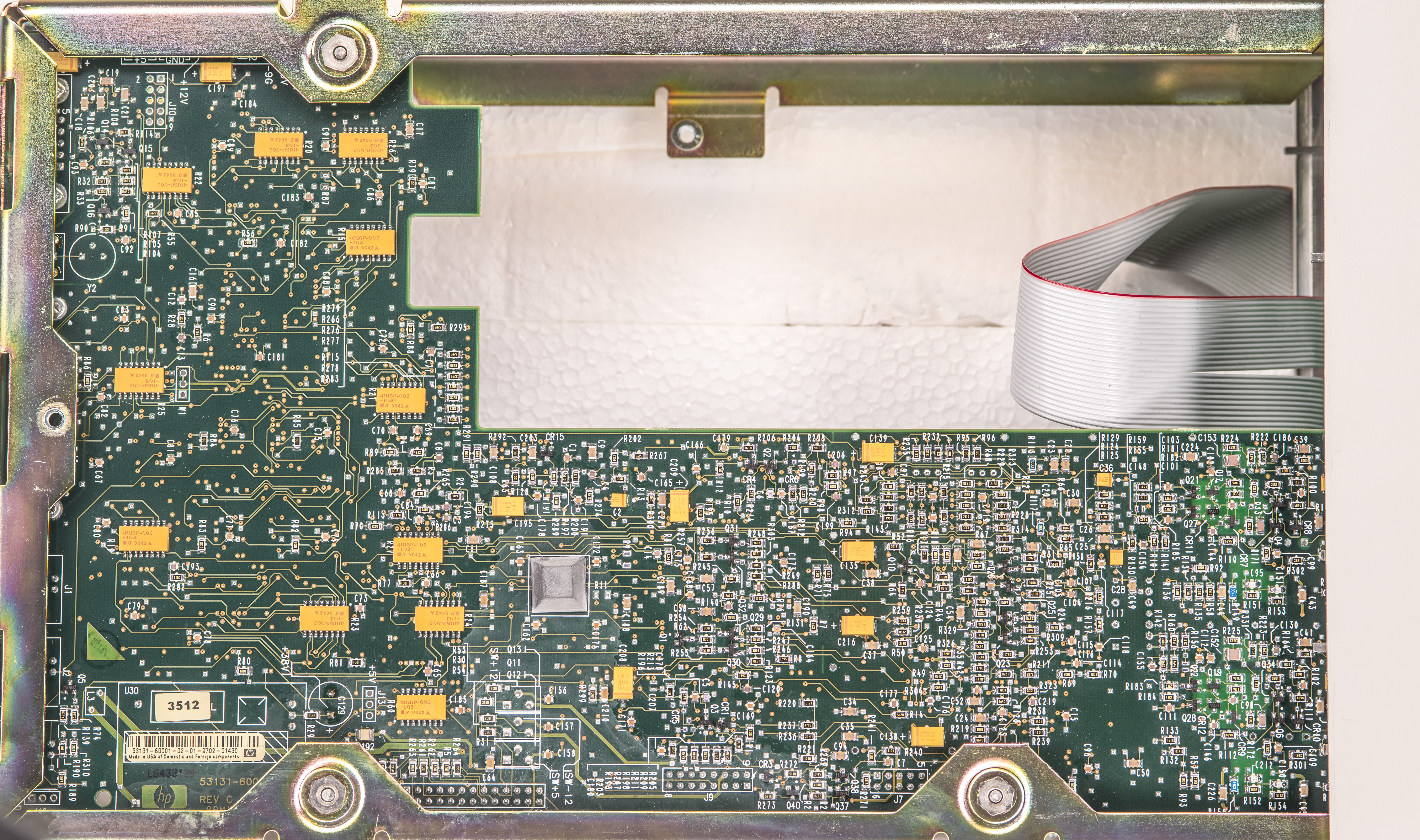
Image 3: Bottom side view on mainboard
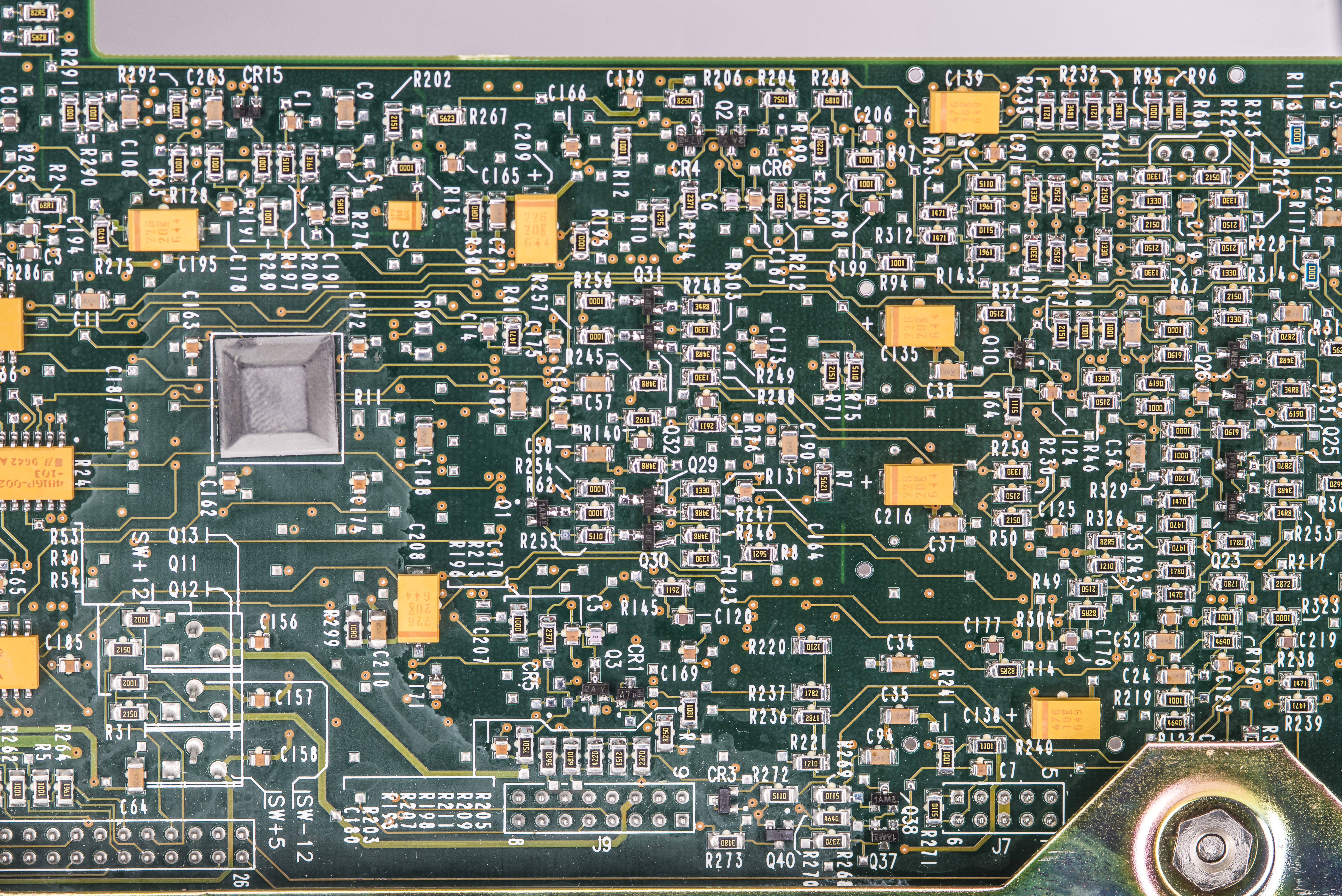
Image 4: Close-up on the bottom side near Xilinx logic devices area
Powersupply, input IEC mains jack and fan are all mounted on metal frame making it very nice and modular. Frame is mounted to counter’s chassis with three torx head bolts, one inside of the chassis and two externally from the rear of the instrument. Only connection between power supply and mainboard is pin header cable on the side. Overall very serviceable design.
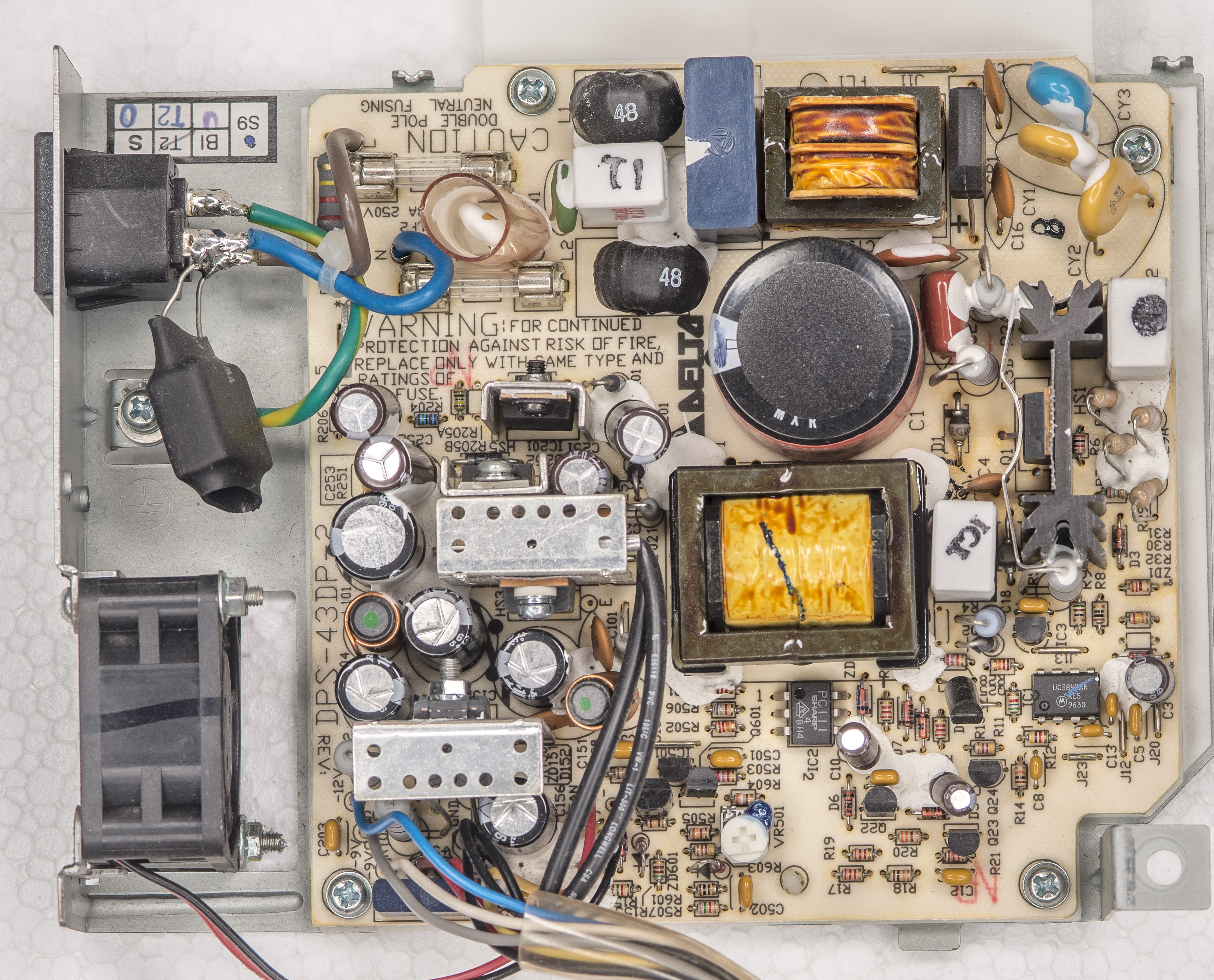
Image 5: Delta DPS-43DP-2 power supply assembly
This power supply is designed by Delta Electronics for HP, marked as revision B1 and accepts universal 100 – 240 VAC input with frequency up to 440 Hz. Output power rating is 47 W. There are four DC voltages available at the output of the module. HP assigned custom part number 0950-2496.
- V1 : +5 V with nominal current rating 5 A.
- V2 : +12 V with nominal current rating 2.1 A.
- V3 : -9 V with nominal current rating 0.25 A.
- V4 : -12 V with nominal current rating 0.28 A.
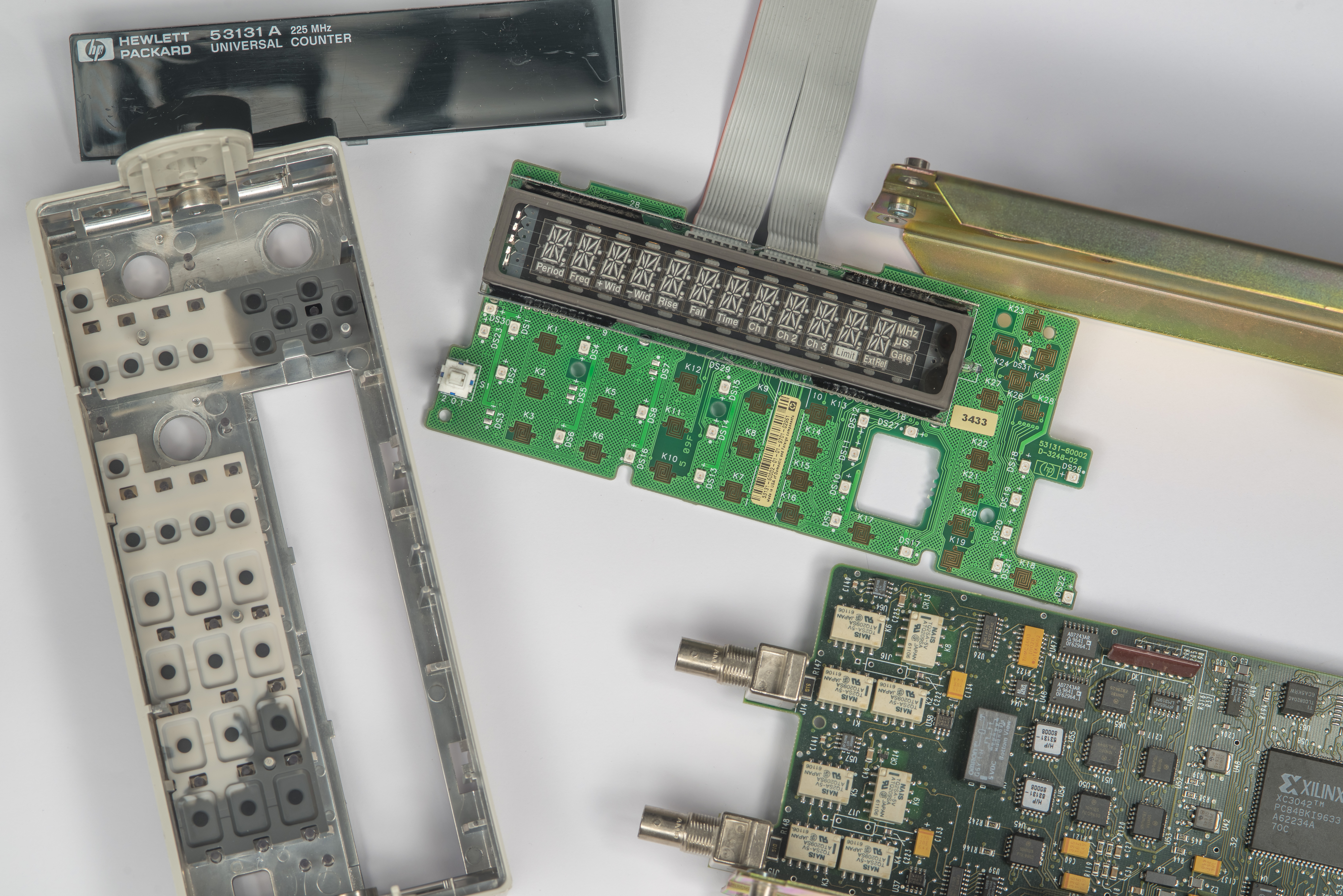
Image 6: Disassembled front panel with PCBA, plastic frame and lens
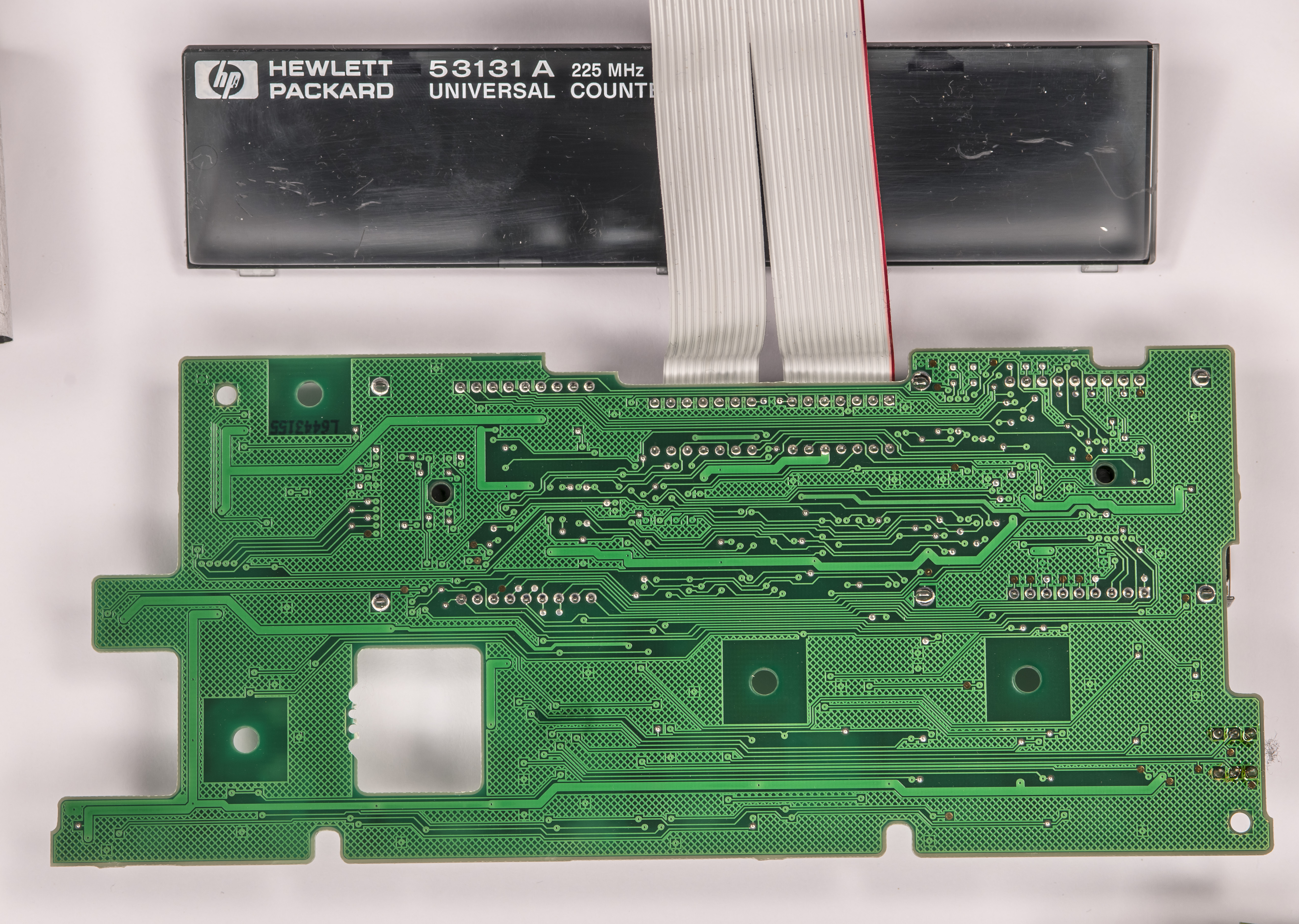
Image 7: Front panel PCBA bottom side
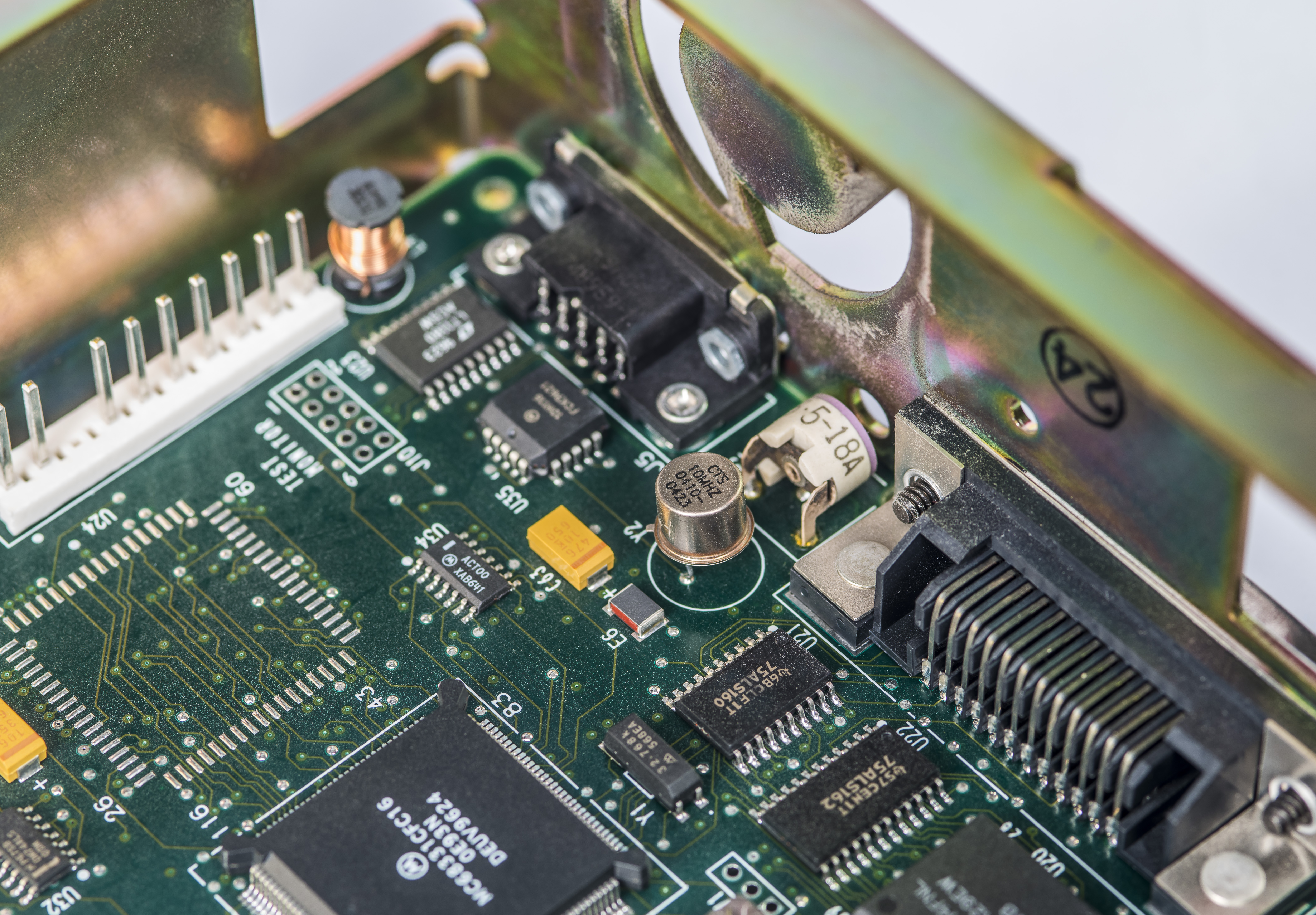
Image 8: Main 10 MHz oscillator and adjustment capacitor trim near the I/O ports
Newer 5313X boards use updated design with soldered on PROM memory chips and DC-DC converter for display.

Image 9: EEPROM chips in sockets and DC-DC module
Both inputs in 53131A are pretty identical and have very similar layout. J16 and J17 are positions for rear BNC input connectors option.
Image 10: Input switching and front end components
Newer units have integrated DC-DC supply in the right back corner, but in this old unit it’s still separate module HP P/N 0950-2325 near to J6 and C129 capacitor. This module converts main +5 V DC input voltage into +38 V DC for segment drivers and AC voltage for filament heater.
Image 11: DC-DC module with TDK transformer, used for VFD glass
Image 12: Xilinx XC3042 logic device and space for U59 and U60/U61/U5 devices reserved for 53132A
Image 13: Active devices for the inputs front-end
Also a quick look on the 3 GHz third channel option 030 module that came with this 53131A. There are also number of aftermarket PCB modules such at these that provide this option ch3 functionality but we got original HP-made 030 module in this counter.
Image 14: High resolution panoramic image of 53131A mainboard, top side
Image 15: Optional channel 3 GHz preamp/divider PCBA, top component side
It is original HP 53132-60003 module done on two layer PCB with row of RF amplifiers and frequency divider. TheSignalPath blog has this very nice video explaining the design, functionality and performance of this option 030. I’d recommend to watch it for details about 030 option operation. This optional PCBA is mounted with four bolts and components facing towards metal frame of the counter.
Image 16: Optional channel 3 GHz preamp/divider PCBA, bottom solder side
On the bottom side we have just solid copper ground pour, providing good and low impedance reference plane to maintain 50 Ω signal transmission environment. Only component here is J1 – SMB connector for the input cable connection. Higher 12.4 GHz frequency option using similar design concept with RF input amplification and frequency prescaler.
Agilent 53132A Counter
Other than updated lens with Agilent branding and 53132A model number front panel is completely identical to older HP 53131A.
Image 17: Agilent 53132A front panel user interface
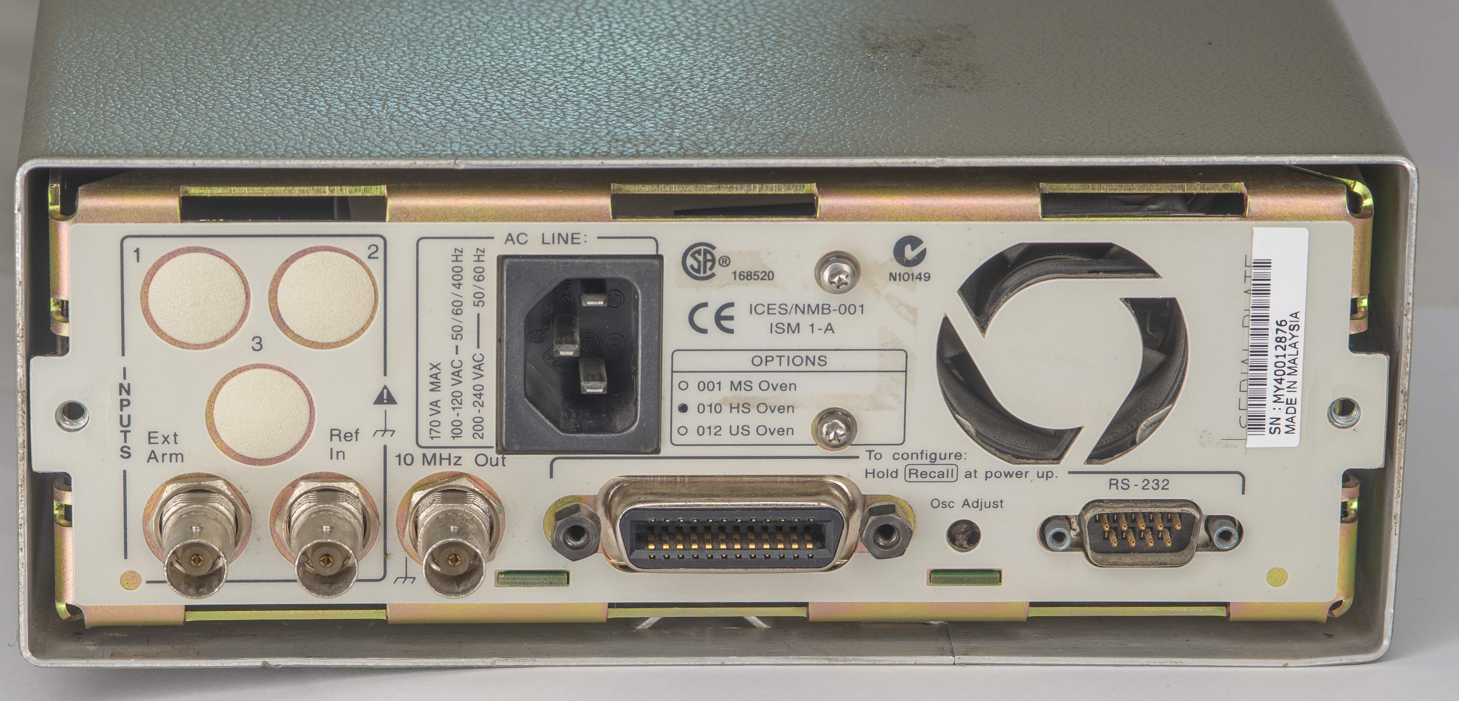
Image 18: Agiletn 53132A rear connectors and fan exhaust vent
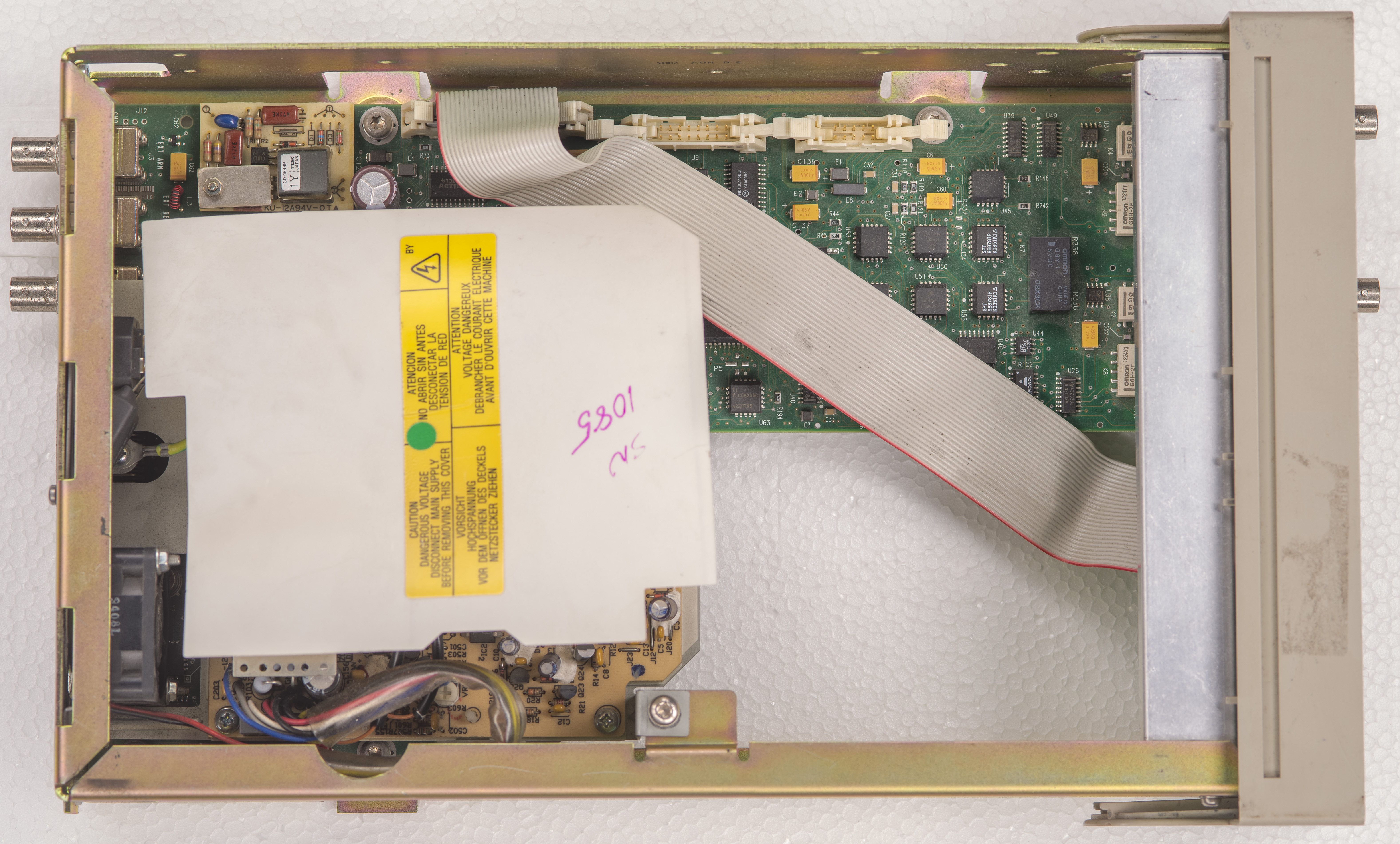
Image 19: Top side view on 53132A hardware, with PSU assembly installed
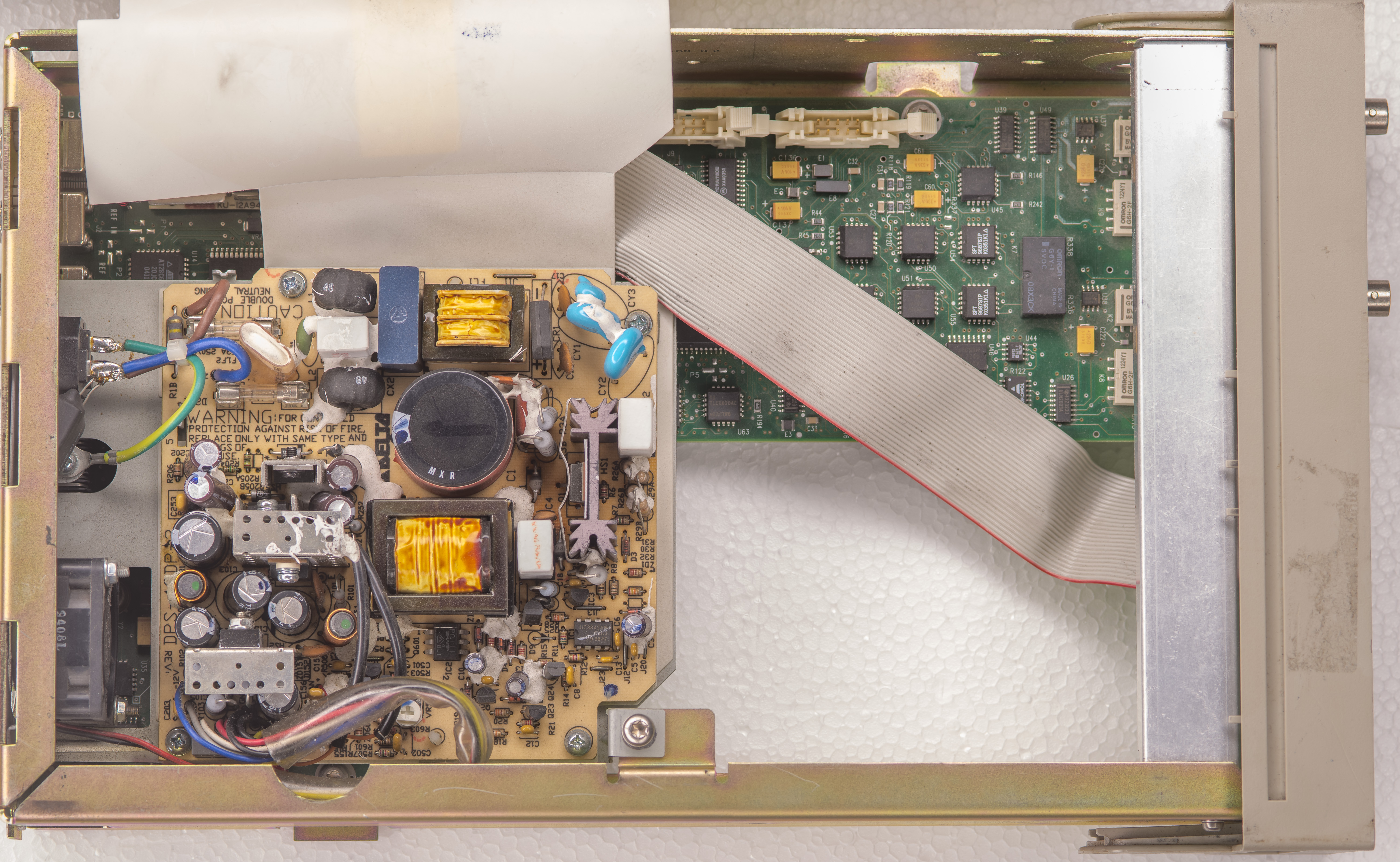
Image 20: Power supply view with isolation plastic folded away
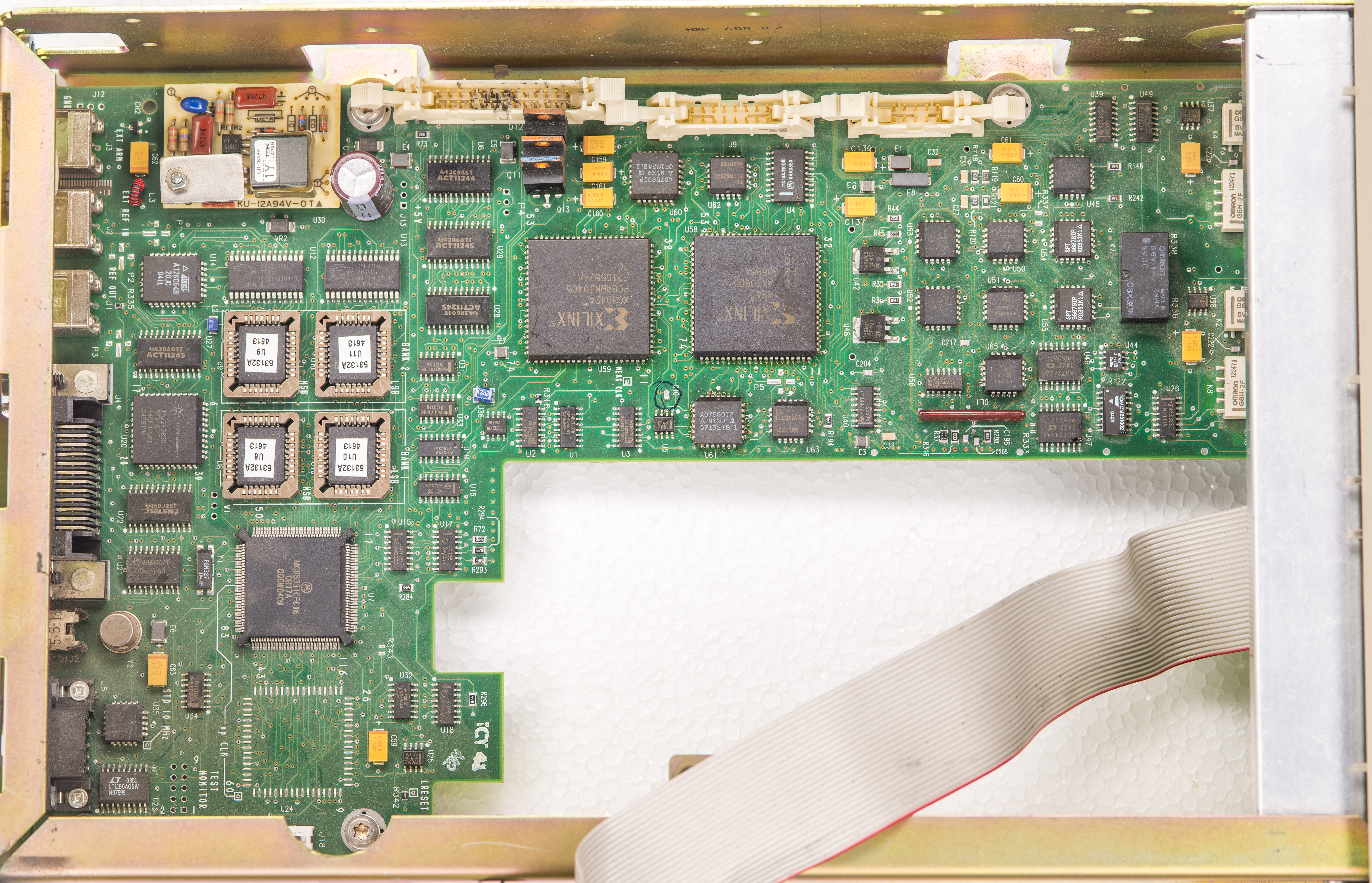
Image 21: Top side with PSU assembly removed

Image 22: Bottom side view in 53132A counter
Back side of the motherboard has bunch of circles marked with black sharpie around some resistors and capacitors in the center area. Bunch of other components also have clearly visible flux residue, perhaps by previous modifications or repairs?
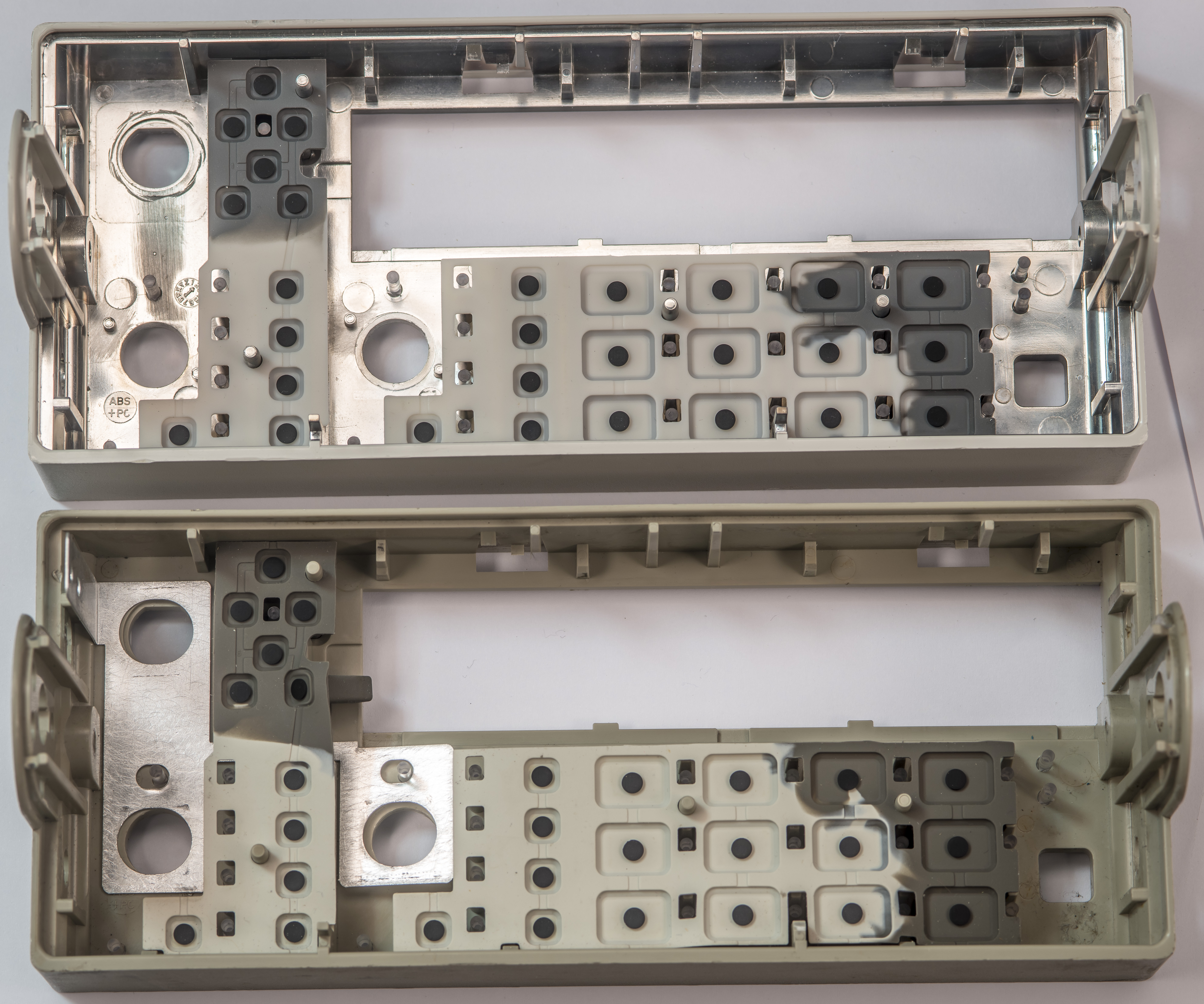
Image 23: Front panel plastics comparison between two counters
Interesting to note difference in front panel design. Front panel from older 53131A shown on the top and newer 53132A panel is on the bottom. Older 53131A instrument had shiny metallization layer on the inside surfaces, while newer 53132A front panel is boring plain injection molded plastic plus added thin aluminum plate around BNC connectors area. Maybe HP guys decided to cost-down the front panel tooling to save on plating surfaces process?
Power supply in this 53132A is identical Delta DPS2 unit as we saw in 53131A counter. All counters in these series use same power supply assembly.
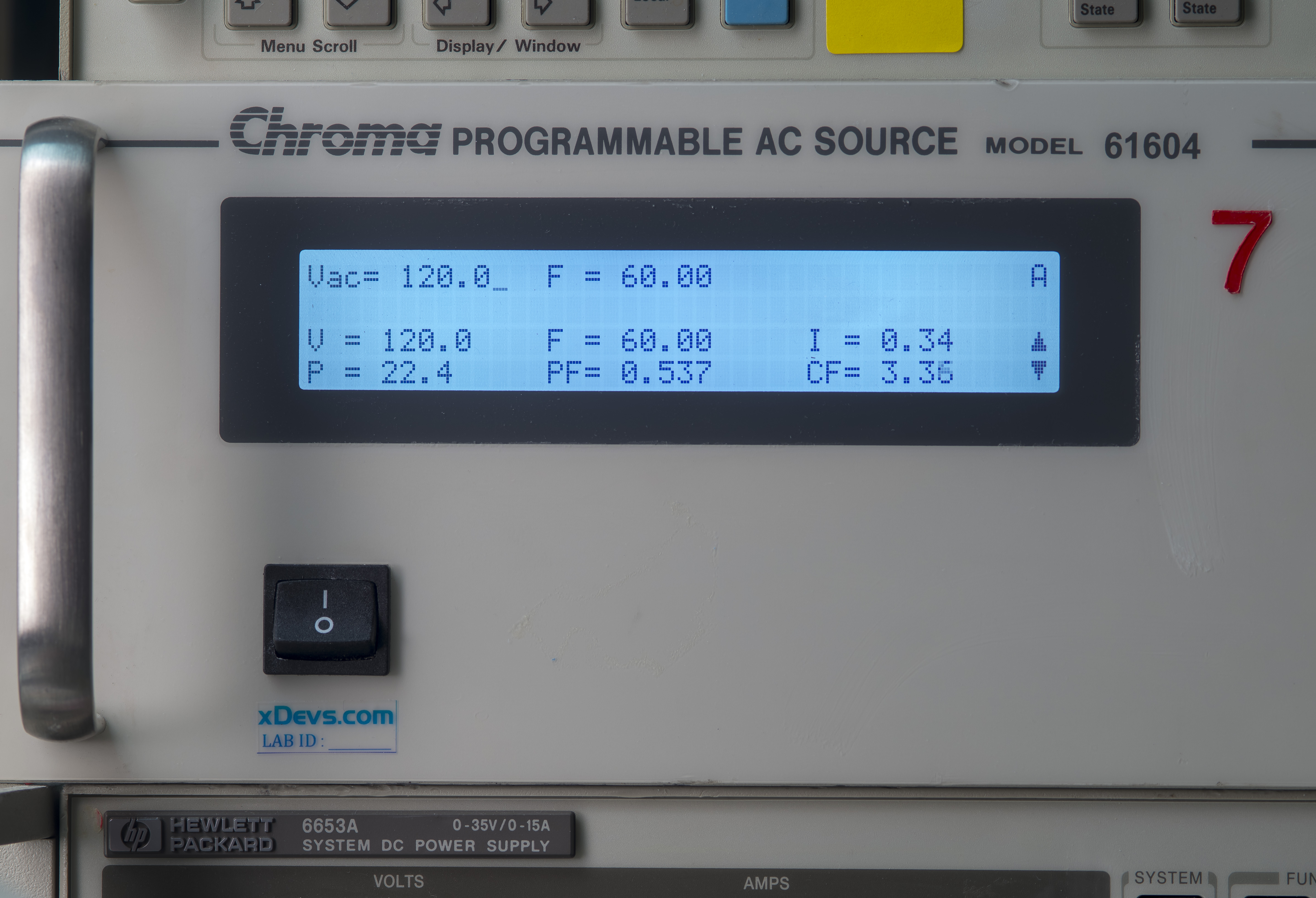
Image 24: Power consumption of powered up Agilent 53132A with good power supply, around 22.5 W
Problem with this 53132A is obvious when we take a closer look on Delta power supply. With 120 V mains connected instrument was just generating short 10 W power consumption spikes with zero signs of life.
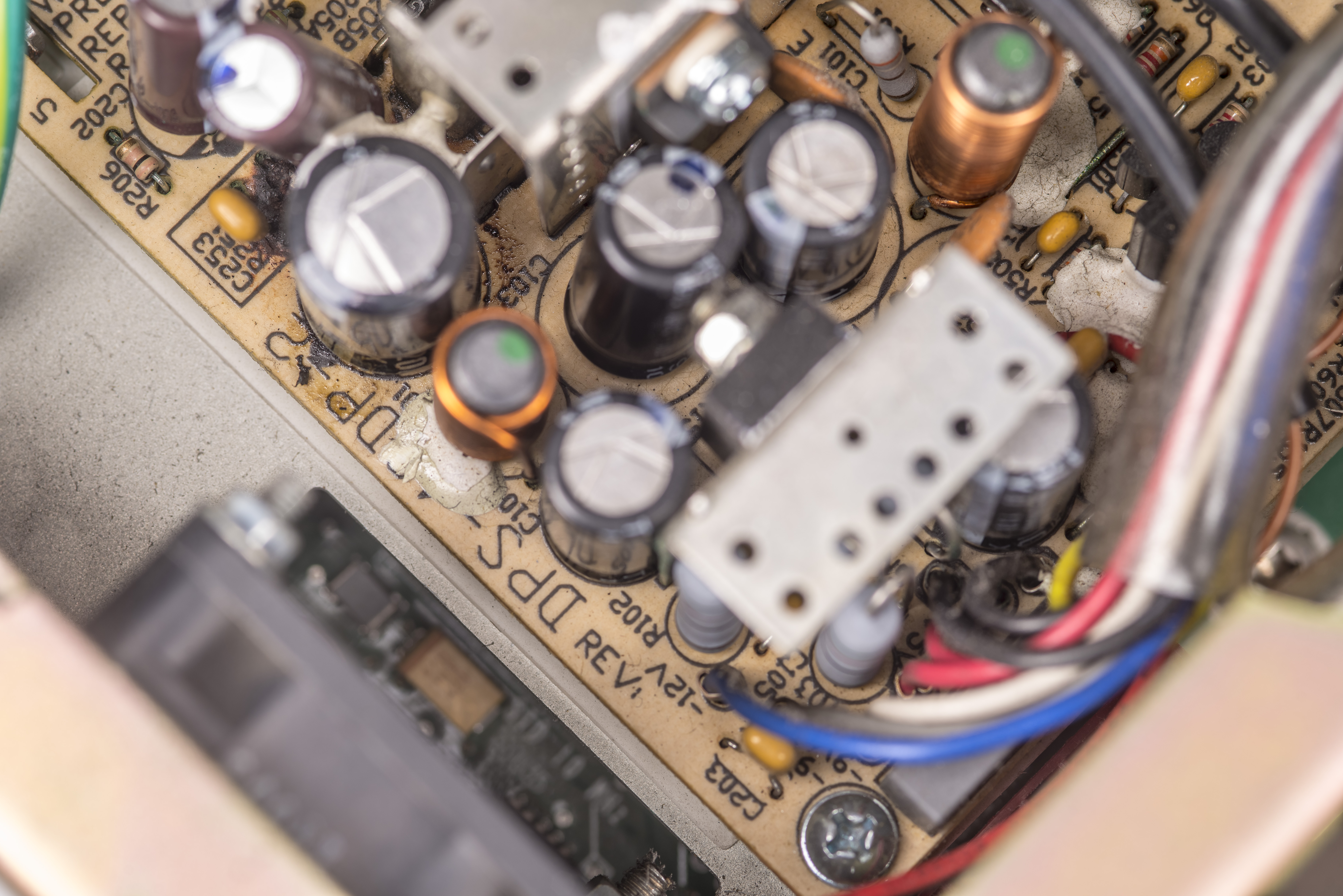
Image 25: Leaking electrolyte around C103
This pulsed behavior is a tell-tale of broken switch-mode power supply, very often due to damaged active components or old bad electrolytic capacitors. And closer look indeed reveals leaked nasty goo under one of the Rubycon black capacitor. PSU in these counters is always powered on and running as soon as the power cable is plugged which does not help with reliability over the years. It is interesting to note that this PSU with leaked cap was manufactured in late 1999, while still working good PSU in 53131A is 3 years older.
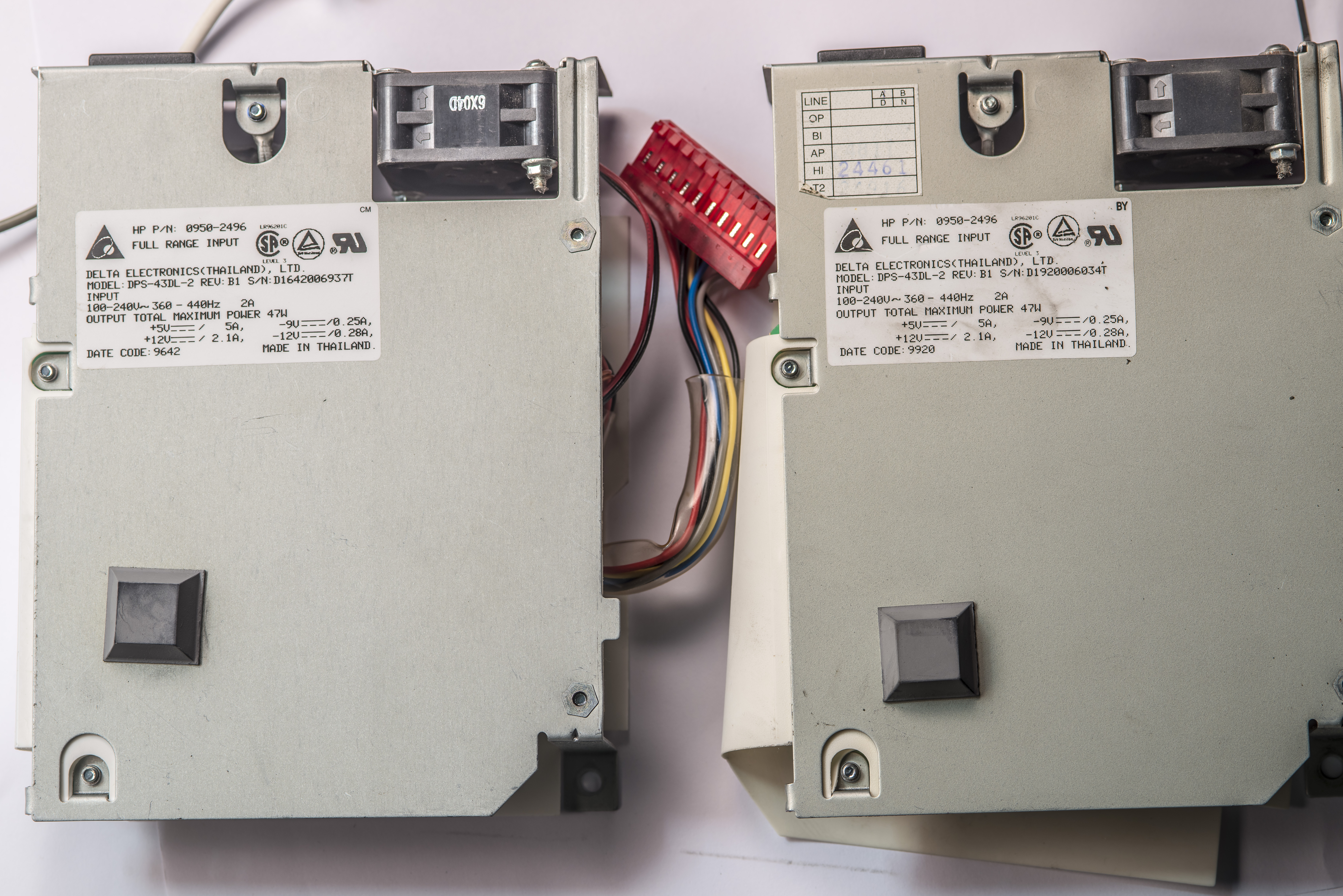
Image 26: Power supply labels
The usual approach for old equipment repairs at xDevs labs is to replace all electrolytic capacitors in power supplies, no questions asked. I don’t even bother checking the capacitors, as the price for replacement caps often is far less than 1% of the overall instrument cost. Unlike good wine, electrolytic and tantalum capacitors do NOT improve with age. So many times a bad $1 capacitor was a cause of destruction to the expensive and hard to find active components or transformers that this refurbishment service for every old instrument is a solid approach to keep the lab up and running. In worst case, you just replaced good old capacitors with good new capacitors, loosing only a little bit of time in return.
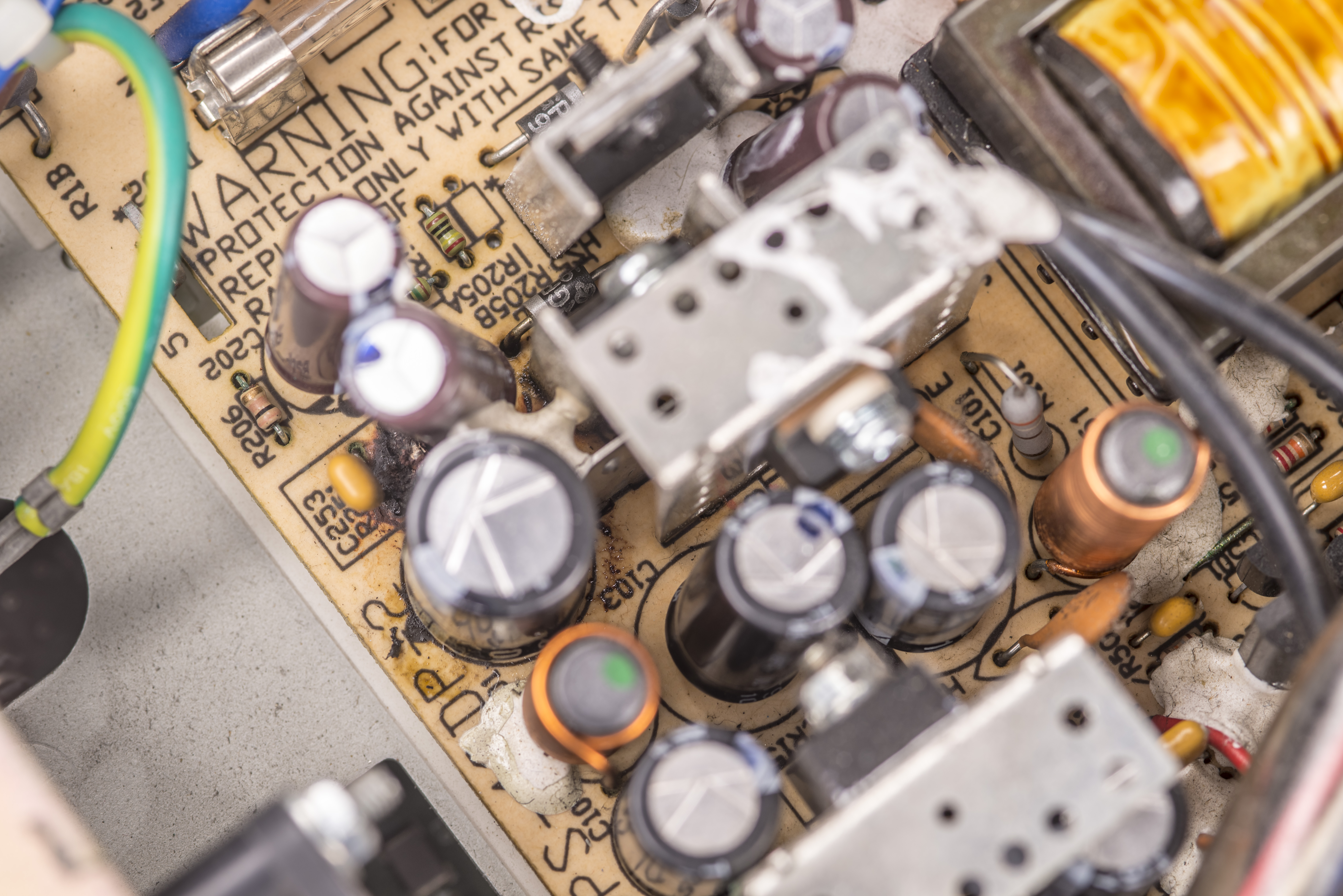
Image 27: Blown up R251 next to leaking C103 capacitor
Previous users of these instruments already finished reverse-engineering for this Delta PSU which can be very handy for our repairs.
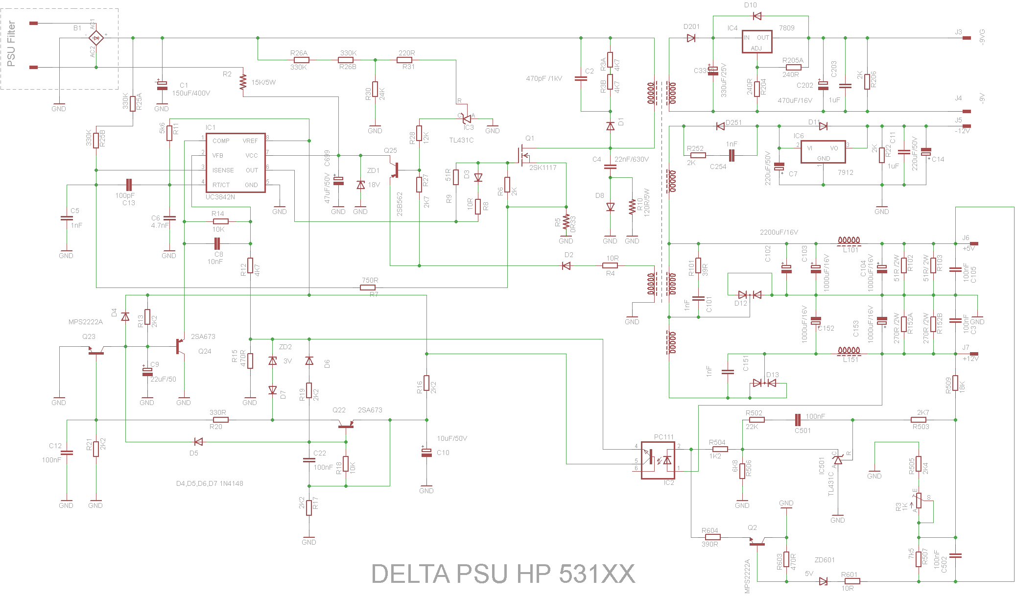
Image 28: Schematics of this Delta PSU, reverse-engineered by forum member .
Always-on design was implemented on purpose, since high-stability or ultra-stable option in these counters require some hours to get stable and up to temperature. HP designers decided to make instrument always running hot instead of putting a requirement to wait warm-up time on the user. I understand the idea to have an instrument always capable to provide accurate measurements the moment it is powered up, but still am not sure if I like this design approach and constant 10 W of vampire power draw even when not in use. Imagine having a lab with a few dozen of these counters sitting plugged, but turned off. After all, the idea of waiting for multiple hours is very common in DC and resistance metrology, including many HP/Agilent/Keysight DMM. Maybe time/frequency people are not as patient and DC/LF metrologists? 
Quick look inside current Keysight 53230A and option 015
I also have few photos of modern Keysight 53230A counter equipped with 15 GHz 3rd input option. This new counter was manufactured in the end of 2017 and came with faulty 15 GHz input.
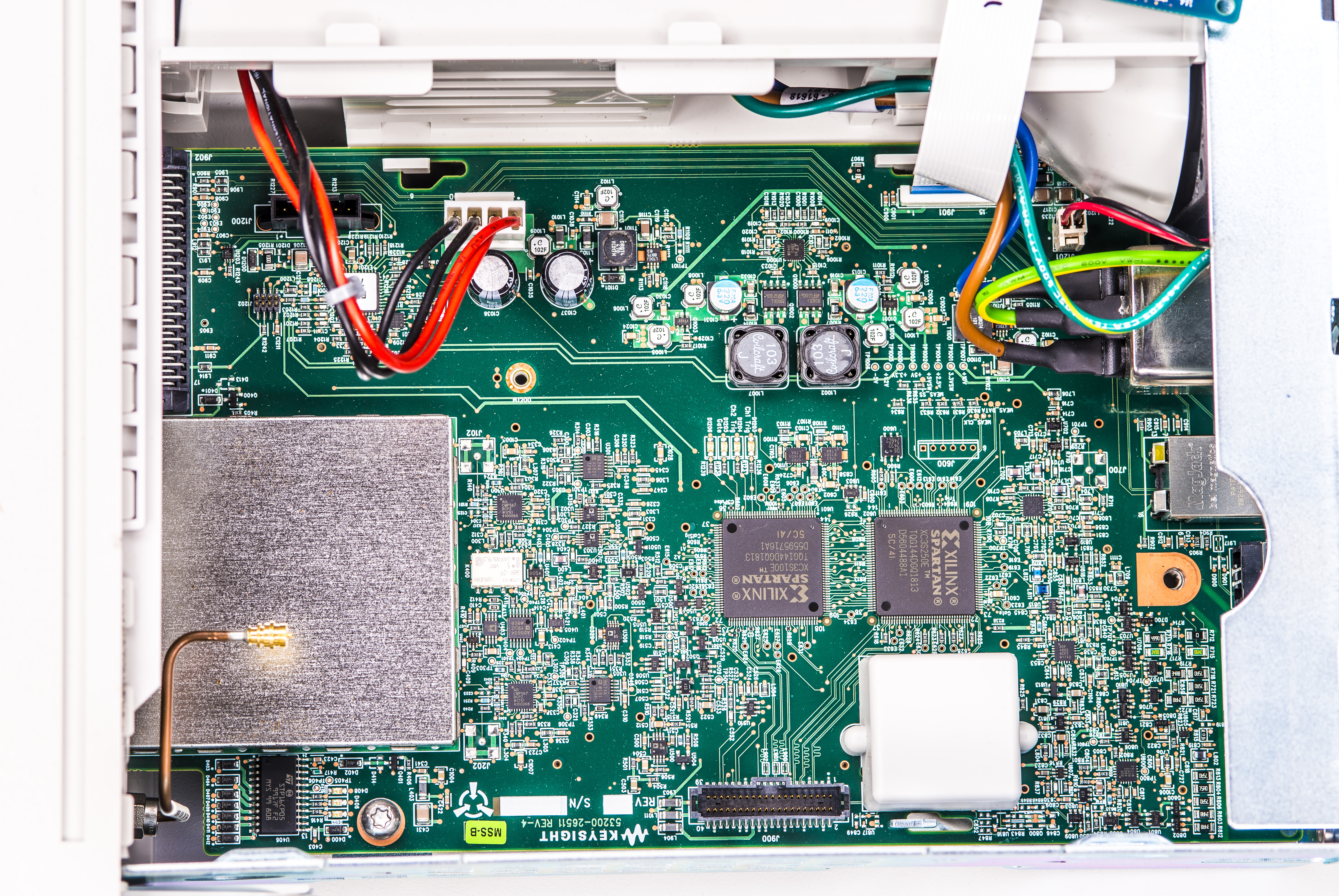
Architecture was refreshed quite a lot with most of components in small SMT packages, with updated to Spartan-3 XC2S350E and XC3S100E FPGAs in the center. Other notable chips are Analog Devices ADCMP567BCPZ ultrafast comparator , AD8674A , ADF4002BCPZ 400 MHz PLL/Phase detector , LTC3850 2-phase DC-DC.
Microwave 15 GHz option came with Keysight P/N 53200-66516 and had properly designed high-speed PCB with Rogers substrate under top copper layer to ensure low loss and good RF performance. Front edge-launched SMA connector had tiny AC coupling capacitor and bunch of proprietary Keysight ASICs.
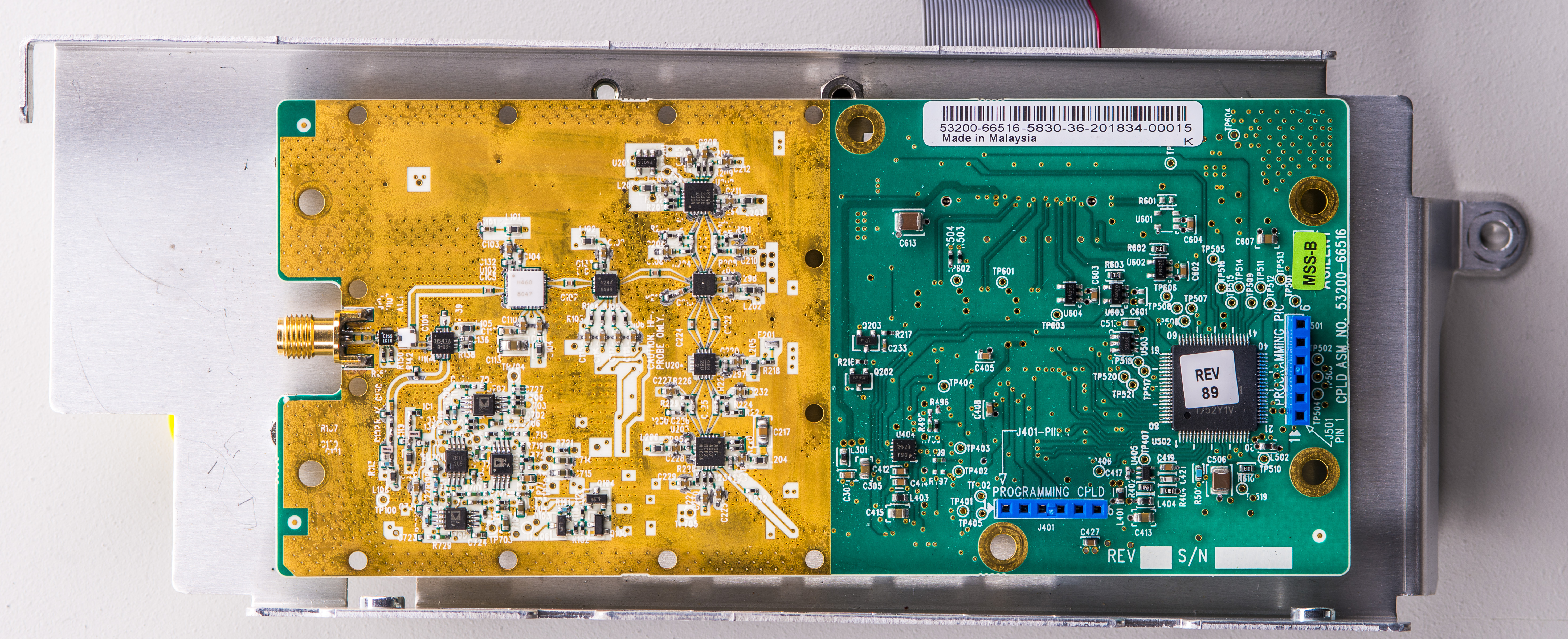
It was only repaired because of support from Steve who had the donor board from another Keysight product to steal the needed unobtanium ASIC chips. This board was also filled with Hittite RF components such as HMC547A switch , HMC760 4 GSPS 5 GHz Track-and-Hold amplifier , HMC424 digital attenuator and HMC493 InGaP HBT Divider-by-4 and some others. Some of these parts are quite expensive, such as HMC760 at $343.47 each.
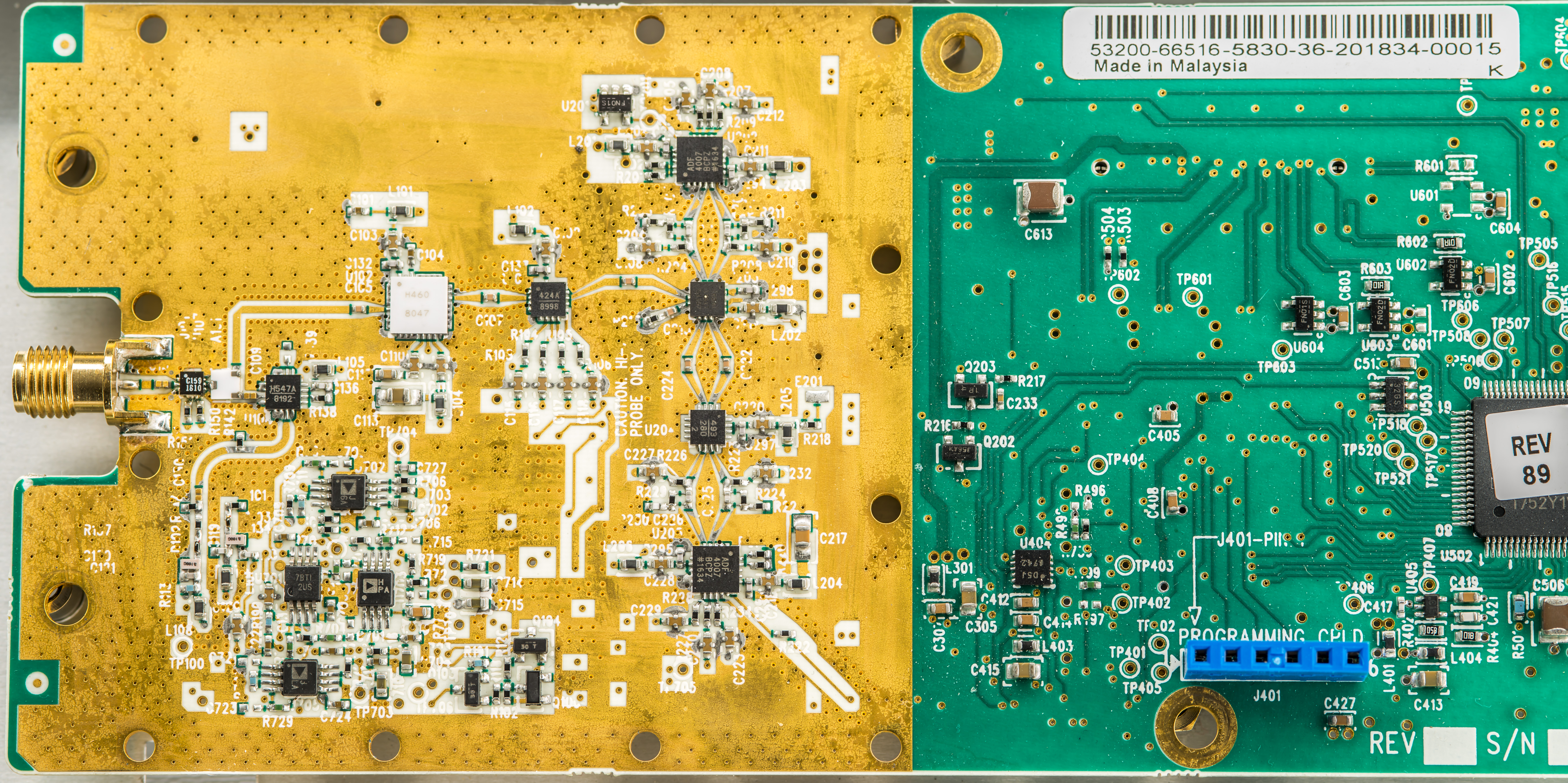
It was also quite tricky to get these soldered in because of massive copper polygon pours with dense via fences. Ideally, such boards should be reworked with good preheating table to avoid stressing sensitive components with excessive heat. Remember, soldering is all about thermal transfer and NOT the temperature. If the solder does not melt at +270 °C then there is too much thermal power loss or not enough heat power applied. Increasing temperature would NOT help and only increase risk of damaging and overheating PCB or components on it.
Difference between 53131A and 53132A and possible DIY upgrade
Both counters capable to measure frequency with resolution up to 12 digits, but cheaper 53131A model needs more time to do it. From hardware perspective difference is in firmware, additional logic array chip, extra 10-bit SAR ADC ICs and few resistors and capacitors for power delivery network for extra chips. Both of these extra chips are long obsolete now and hard to find. The best option for tinkerers would be to find broken 53132A and salvage chips from there, if there is a need to upgrade 53131A a little. All hardware components differences are summarized in a table below.
| 53131A counter | 53132A counter | |
|---|---|---|
| U5 | Empty | Obsolete +2.5V Voltage reference, STMicroelectronics MC1403D in SOIC8, HP P/N 1826-1848 |
| U59 | Empty | Obsolete in 2012 Xilinx XC3042A-7PC84C 84-pin J-lead LCC FPGA |
| U60 | Empty | Obsolete Analog Devices AD7580JP ADC |
| U61 | Empty | Obsolete Analog Devices AD7580JP ADC |
| R299 | populated, 1206 10 Ω resistor | |
| R300 | populated, 1206 10 Ω resistor | |
| R11 | Empty | populated, 1206 5.62 kΩ resistor |
| R9 | Empty | populated, 1206 5.62 kΩ resistor |
| C10 | Empty | populated, 0805 10 nF capacitor |
| C207 | Empty | populated, 0805 10 nF capacitor |
| C210 | populated, 1206 100 nF X7R capacitor | |
For this article I’ve just took channel 3 option, good (or bad, but still working?) power supply and nicer whiter front panel from 53131A and transplated into 53132A chassis to get a good working Agilent 53132A counter and project for future repair in shape of bad PSU and ugly browned 53131A FP.
Some measurements and benchmarks
Now that we got nice looking Agilent 53132A unit with three inputs, it is time to do some measurements with it. For first test I’ve checked that all three inputs are functional and provide reasonably accurate reading. This was done with connecting each of the counter inputs to our HP E4436A ESG-DP RF signal generator and configuring source for +0 dBm sine output with required frequency.
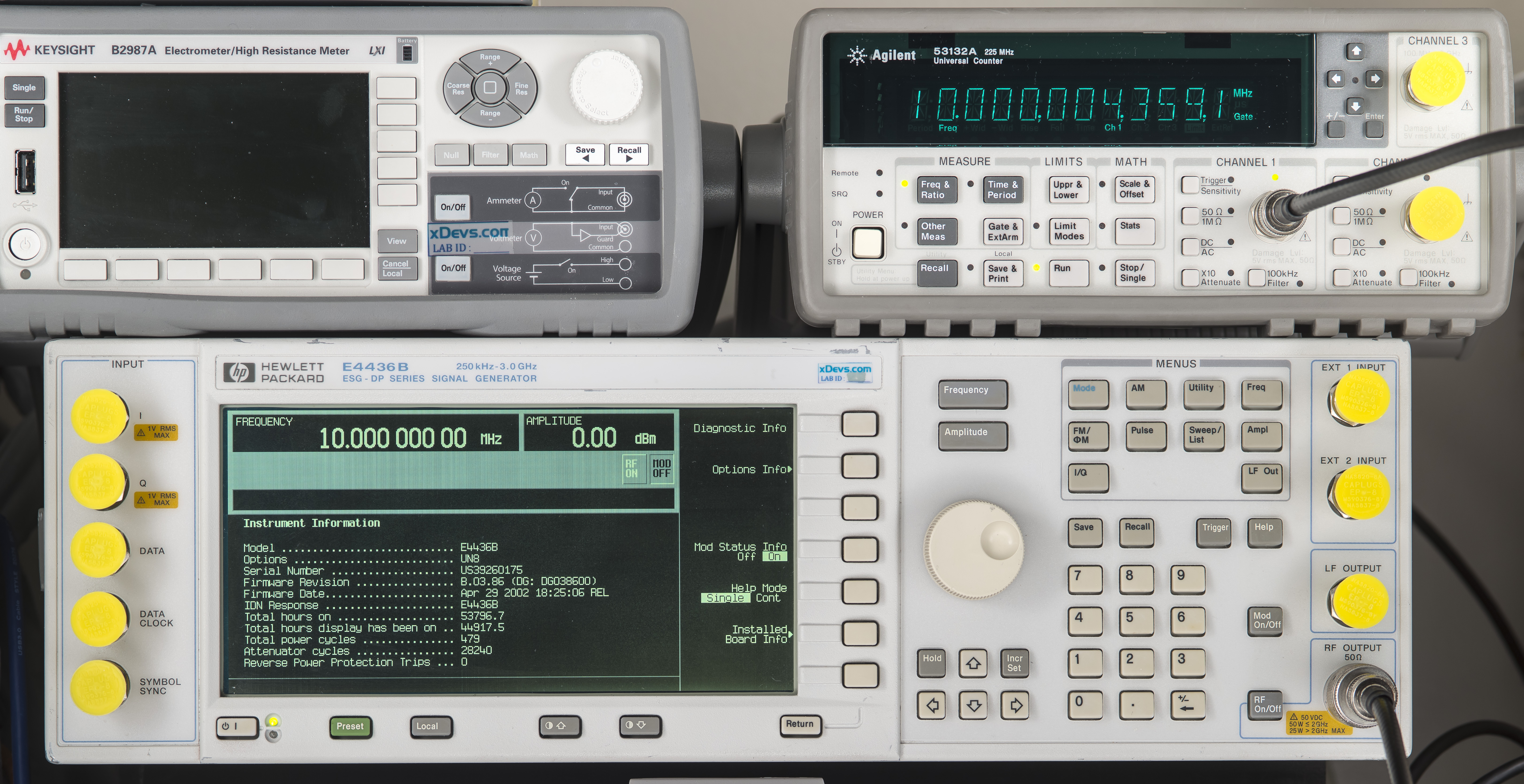
Image 29: Measurement check with 10 MHz signal applied
Basic 10 MHz measurements worked well without any issues. Next is 3 GHz for input 3:
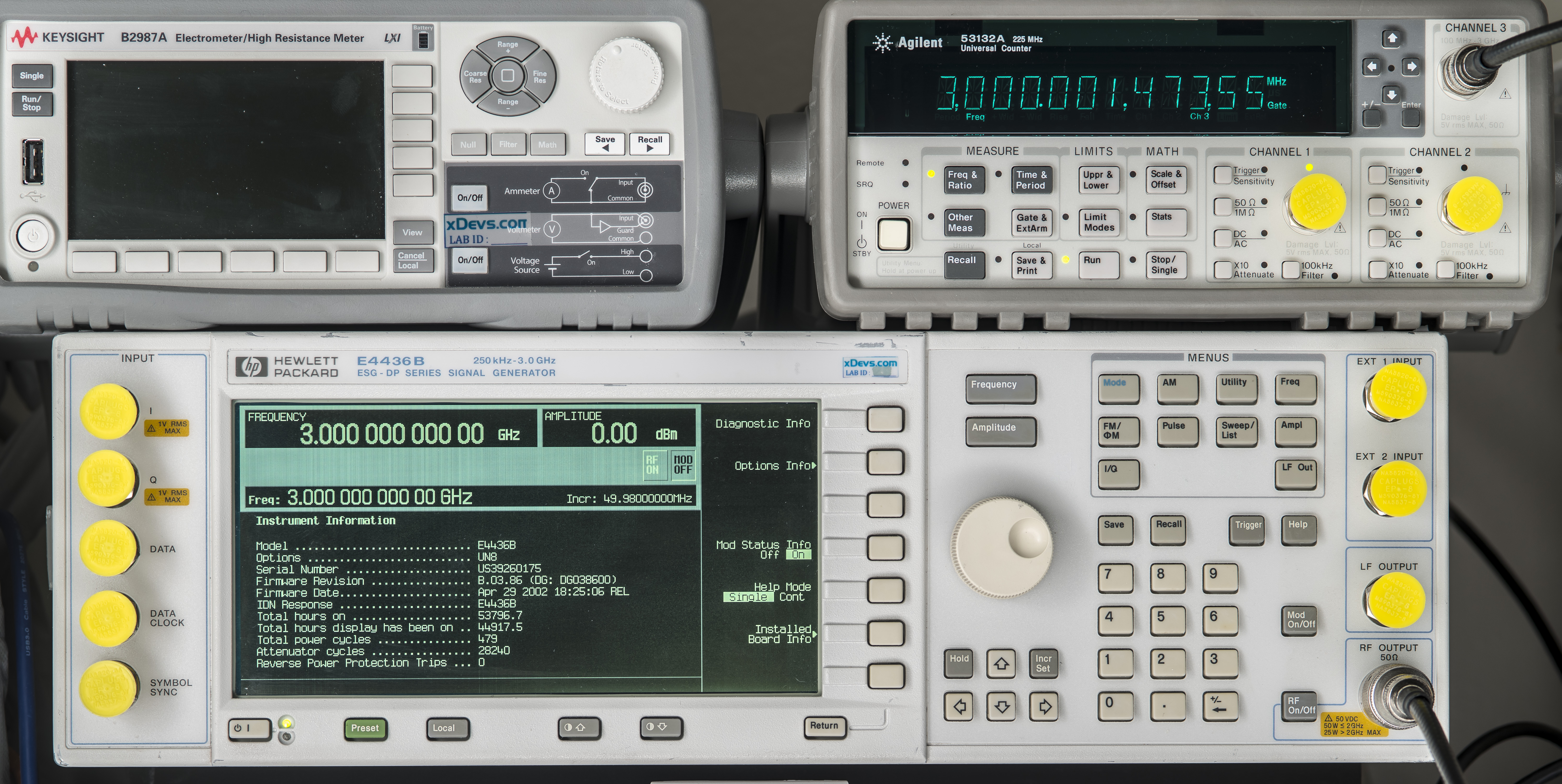
Image 30: Measurement check with 3000 MHz +0 dBm signal applied to input 3
Also no problems detected in measuring the 3000 MHz signal. References between generator and counters were not locked together, and no ajustments were performed either.
These 5313X series counters as well as newer 53200 series supported by very powerful and useful TimeLab software developed by John Miles KE5FX. This software is extremely versatile and can make automated precision time and frequency measurements, including Allan deviation, MDEV, TDEV, MTIE, phase noise, and phase/frequency drift.
Summary and conclusion
Overall this was a fun little evening project swapping some parts in 53131A and 53132A counters, looking at overall design and measuring some GHz signals. These counters will be a valuable addition to xDevs.com lab instrumentation for future AC/DC metrology and digitizer projects.
RF instrumentation is still a very much far out of our main scope of interest, but that does not diminish the interest in circuits and instruments evolved around RF domain of electromagnetic spectrum. In the modern world, RF signals and waveforms are everywhere around us, from the Internet, cell-phones or mundane microwave ovens. And even all the DC voltage metrology is in the end defined by the inverse AC Josephson effect, thanks to JVS cryogenic standards use as ultimate physical implementation of quantum accurate frequency to voltage DAC converter.
Discussion about this article and related stuff is welcome in comment section or at our own IRC chat server: irc.xdevs.com (port 4808, channel: #xDevs.com).
Projects like this are born from passion and a desire to share how things work. Education is the foundation of a healthy society - especially important in today's volatile world. xDevs began as a personal project notepad in Kherson, Ukraine back in 2008 and has grown with support of passionate readers just like you. There are no (and never will be) any ads, sponsors or shareholders behind xDevs.com, just a commitment to inspire and help learning. If you are in a position to help others like us, please consider supporting xDevs.com’s home-country Ukraine in its defense of freedom to speak, freedom to live in peace and freedom to choose their way. You can use official site to support Ukraine – United24 or Help99. Every cent counts.
Modified: Dec. 23, 2025, 5:11 a.m.