Contents
- Intro
- Disclaimer
- Manuals and documentation
- Project concept and workflow
- Modularity and 5700A/5720A flexible diagnostics
- Fluke 5700 ‘B’ Hulk.Jr build
- A4 outguard motherboard
- A19 outguard power supply board
- A20 outguard 5700A processor board
- A21 outguard rear I/O board
- A3 inguard motherboard
- A18 outguard rear I/O board
- A17 outguard rear I/O board
- A11 REF/DAC 5700A type board
- A11 REF/DAC 5720A type board
- A8 – Switch matrix , 5700A board
- A9 outguard rear I/O board
- A10 outguard rear I/O board
- A7 outguard rear I/O board
- A12 – Oscillator
- A13 – Oscillator output, 5720A Rev.U board
- Summary on spent resources
![]()
![]()
![]()
![]()
This is our “spare” calibrator rebuild project, using leftovers and spare boards from first Hulk. Few boards were missing, so they were bought separately to fill the gap.
Remember, buying broken or even listed “tested good” used 5700A below market price and fixing it likely will end up as bad expensive exercise, when all hidden costs are considered and accounted for. Paid cost for such a unit WITH proper repair, long-term verification and demanding calibrations will easily exceed cost of buying a fully tested and calibrated unit from reputable source/distributor. So even if you buy complete calibrator for $5K, you can be easily be rewarded with just pile of unstable/non-fixable parts that would need another $XXK to get even just working again, leave alone meeting specifications.
Disclaimer
Redistribution and use of this article, any parts of it or any images or files referenced in it, in source and binary forms, with or without modification, are permitted provided that the following conditions are met:
- Redistributions of article must retain the above copyright notice, this list of conditions, link to this page (https://xdevs.com/fix/hulk2/) and the following disclaimer.
- Redistributions of files in binary form must reproduce the above copyright notice, this list of conditions, link to this page (https://xdevs.com/fix/hulk2/), and the following disclaimer in the documentation and/or other materials provided with the distribution, for example Readme file.
All information posted here is hosted just for education purposes and provided AS IS. In no event shall the author, xDevs.com site, or any other 3rd party, including Fluke be liable for any special, direct, indirect, or consequential damages or any damages whatsoever resulting from loss of use, data or profits, whether in an action of contract, negligence or other tortuous action, arising out of or in connection with the use or performance of information published here.
If you willing to contribute or add your experience regarding instrument repairs or provide extra information, you can do so following these simple instructions
Manuals and documentation
Fluke does provide all main manuals, including service information for these older calibrators, right on the product page, without requirement of any registration or access requests, unlike Tektronix or Keysight web-sites. Thumbs up for Fluke, way to host the data on your product page, not hiding behind registration forms, “ask a consultant” or other big-dollar marketing obscurity.
Brochure: The 5700A/5720A MFC: Taking Accuracy to New Level
Fluke 5700A/5720A Series II Operator Guide, May 1996, Rev.1
Fluke 5700A/5720A Series II Operators Manual, May 1996, Rev.2
Fluke 5700A/5720A Series II Operators Manual Supplement, Feb 2008, Issue 5
Fluke 5700A/5720A Series II Operators Manual Supplement, Feb 2008, Issue 9
Fluke 5700A/5720A Series II Service Manual, Nov 2007 w/o schematics
Fluke 5700A/5720A Series II Service Manual Supplement, Issue 6
Fluke 5700A/5720A Series II Service Manual Supplement, Issue 9
Fluke 5700A/5720A Series II Getting started, March 2002, Rev.2
Fluke 5700A/5720A Series II Getting started Supplement, Issue 6
Fluke 5700A/5720A Series II Remote Programming Reference Guide
Fluke 5700A Instrument Security Procedures
Fluke 5720A Instrument Security Procedures
Tech data: 5700A->5720A Upgrade Service
Model 5440A-7002 Low Thermal Test Lead Set – Specification
Fluke 5700A, 5720A CE Declaration of Conformity
Service notes
First goes the most important document for repairs/maintenance – 570-page service manual. Credits for hosting it first going to KO4BB portal. We are lucky to also have schematics, list of parts, assembly drawings of the boards included in it!
Fluke 5700A MFC Service Manual with schematics, Rev.9,3/96, March 1996
Fluke 5700A Series II/5720A MFC Service Manual with schematics, Rev.1,3/02, June 1996
5700A Series I and 5700A/5720A Series II difference
According to An evaluation of the 5700A Series II Artifact Calibration document, major changes in Fluke 5700A/5720A Series II are related to Artifact Calibration and high-frequency AC voltage. Artifact Calibration was improved on a number of ranges, to minimize biases. A new interpolation algorithm is also used for lower ACI ranges to provide better performance.
From hardware standpoint, Model 5720/5700 Series II calibrator has a modification to the in-guard microprocessor circuitry and firmware to minimize noise in the low millivolt DC ranges. Also, because of the tighter specifications of the 5720A, there are more carefully selected components, than in the standard 5700A. Lot of circuit tweaks and changes are on A11 REFDAC and A16 Power Amplifier inguard assembly modules. Many tweaks and minor changes on every board in 5720A level hardware address better reliability and stability of the calibrator. Digital processor board A20 firmware are also updated as a result to reflect added functionality.
Project concept and workflow
Over the course of the project author and other members of xDevs community have learned a great lot about inner workings and troubleshooting non-obvious soft-failure issues, such as out of specification output drift or excessive noise. We hope to provide great amount of details in this article about 5700A or 5720A, however some of this gained knowledge is restricted to internal use and will not be published. If you have specific question about 5700A/5720A/5730A you can try asking us online on this page.
Modularity and 5700A/5720A flexible diagnostics
Fluke designers kept everything very modular, relatively easy to troubleshoot and follow. Many of the local functions are contained within one PCBA/module, allowing great deal of per-module repair or diagnostics. Self-test procedure is also very elaborate and runs about 20 minutes to perform hundreds of test and point measurements to provide you comprehensive diagnostics. Most of the circuitry is tested and many faults can be detected just from the self-test messages. This is great help for the Hulk project here, otherwise without having “spare” working 5700A to make “reference” measurements it would be much harder to diagnost and correctly determine faulty conditions in many mixed cases.
Wise approach here is to test minimum amount of modules/boards first , to ensure voltage regulation/power supplies correct operation and all digital control/interfacing work. Experimentally we determined that to provide valid hardware configurations for functionality checks.
| Config, Hardware setup | Modules installed/used | Provided functions |
|---|---|---|
| A, Inguard digital + power test | A3+A4 + A19+A20 + A1+A2 Front panel + A21 | Unit boots firmware, display VFD, hang on error “Guard crossing” |
| B, Inguard + outguard power test | Same as A + A18 PCBA | Unit hangs on “Guard crossing”, but now can check outguard power pre-regulator / filter |
| C, Outguard power test, cross-guard interface | Same as B + A17 PCBA | Unit boots, allow to navigate menus, but no any outputs/functions |
| D, DCV function test | Same as C + A8 and A11 PCBA | Unit boots, allow to output 220mV,2.2V,11/22V DC Voltage |
| E, DCV+Resistance function test | Save as D + A7,A9,A10 PCBA | Unit boots, adds Resistance and DC Current 220 µA – 220 mA |
| F, ACV function test | Same as E + A12,A13 PCBA | Unit boots, adds ACV and ACI functions, except 2.2A and 1kV ranges, ACAL can be finished |
| G, HV/HC test | Same as F + A14,A15,A16 PCBA | Base configuration, adds 2.2A and 220V,1kV ranges. ACAL fully enabled |
| K, Wideband option | K + Add optional A5+A6 PCBA | Full configuration with 2.2mV – 3.5V 30MHz Wideband option |
| W, Boosted option | Connect 5725A to expansion port | Enables 11A DCI and ACI, extends V/F limits for 1kVAC range |
Configurations in bold letters allow complete self-test and artifact calibration procedures to be completed without errors. Calibrator in this article will be rebuilt to “F level. We have no plans to go further, as that would require finding rather expensive A14/A15 and WB modules. Since xDevs.com already have all these in main Hulk 5720A calibrator, it was decided not to duplicate the functionality here.
Fluke 5700 “B” Hulk.Jr build
Let’s go ahead with worklog on repairs and testing, module by module, part by part.
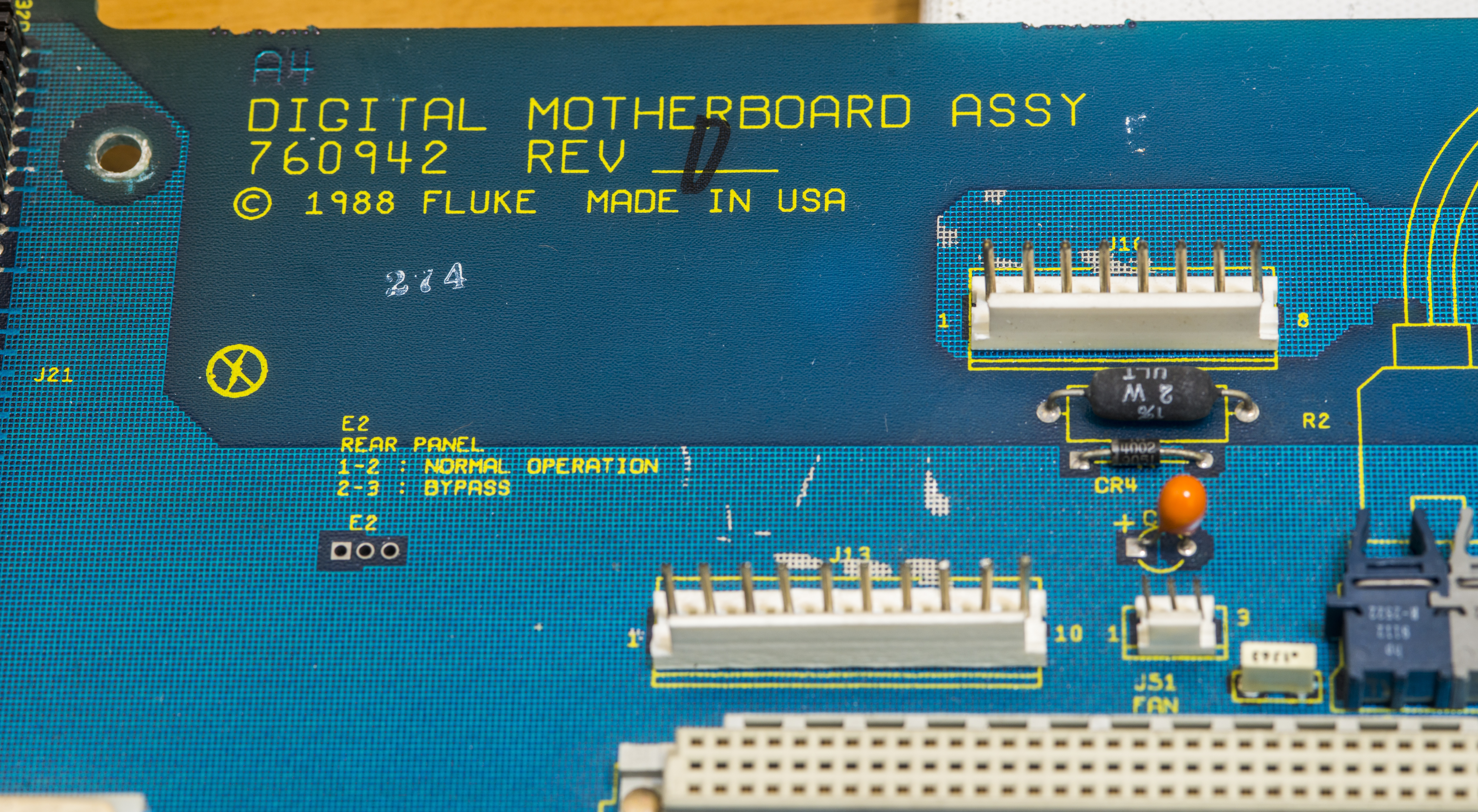
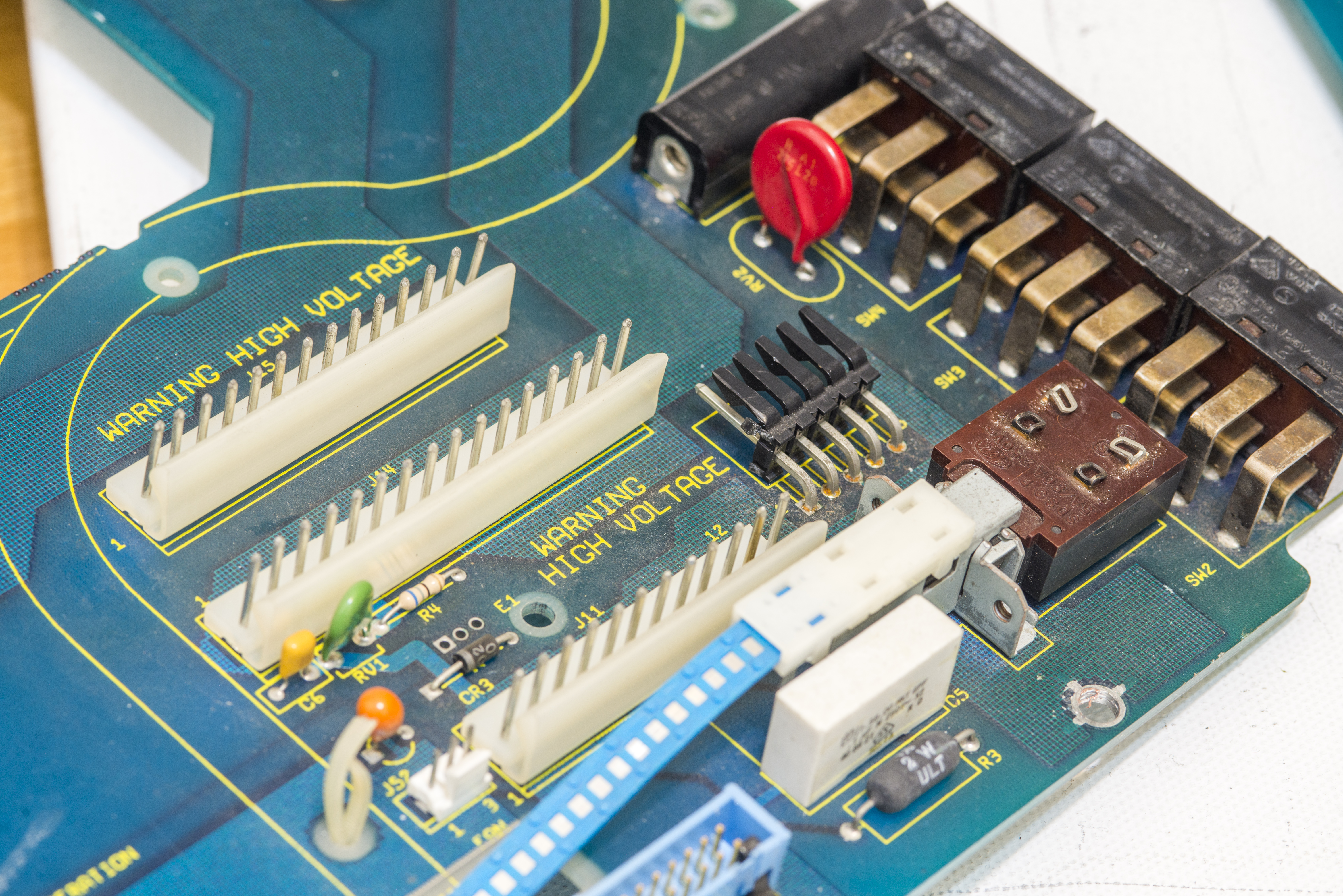
A4 outguard motherboard

A19 outguard power supply board
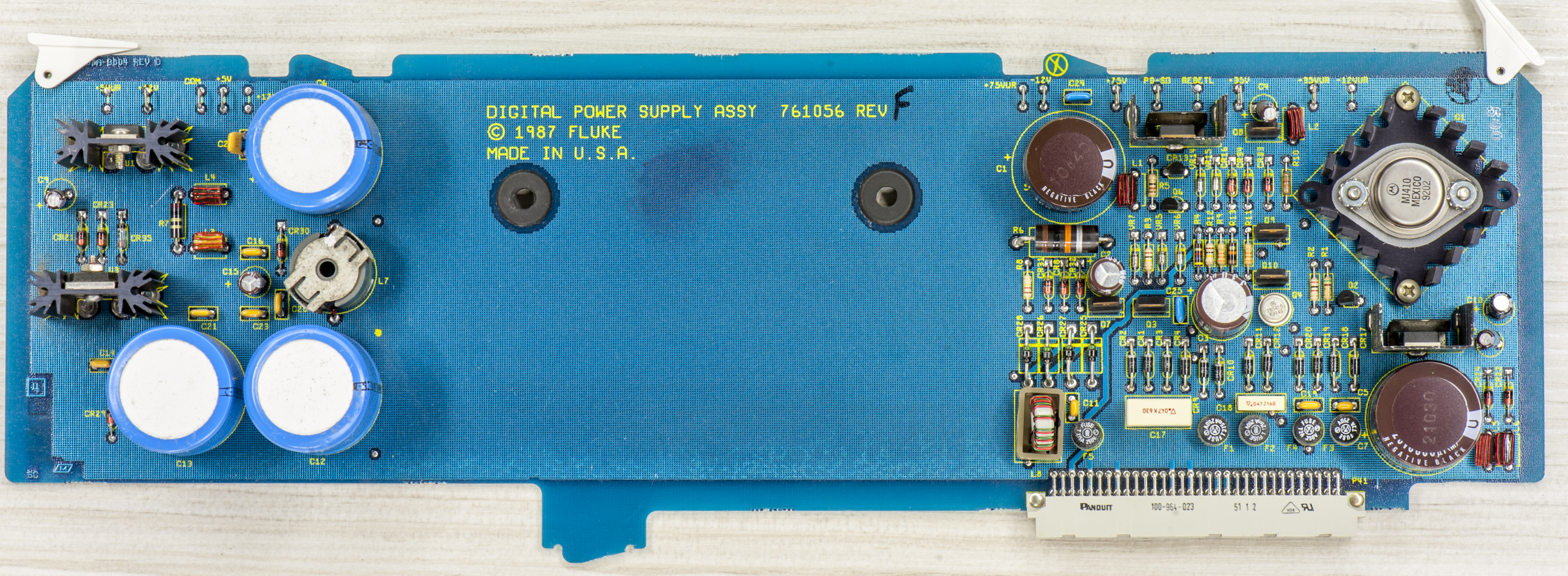
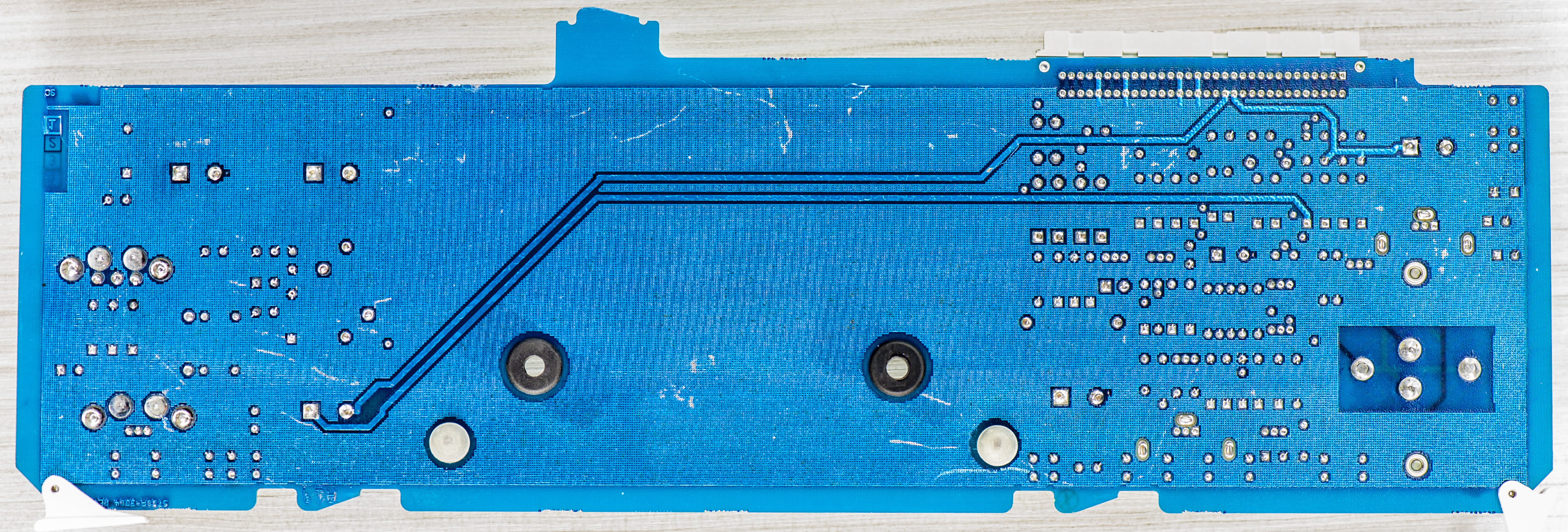
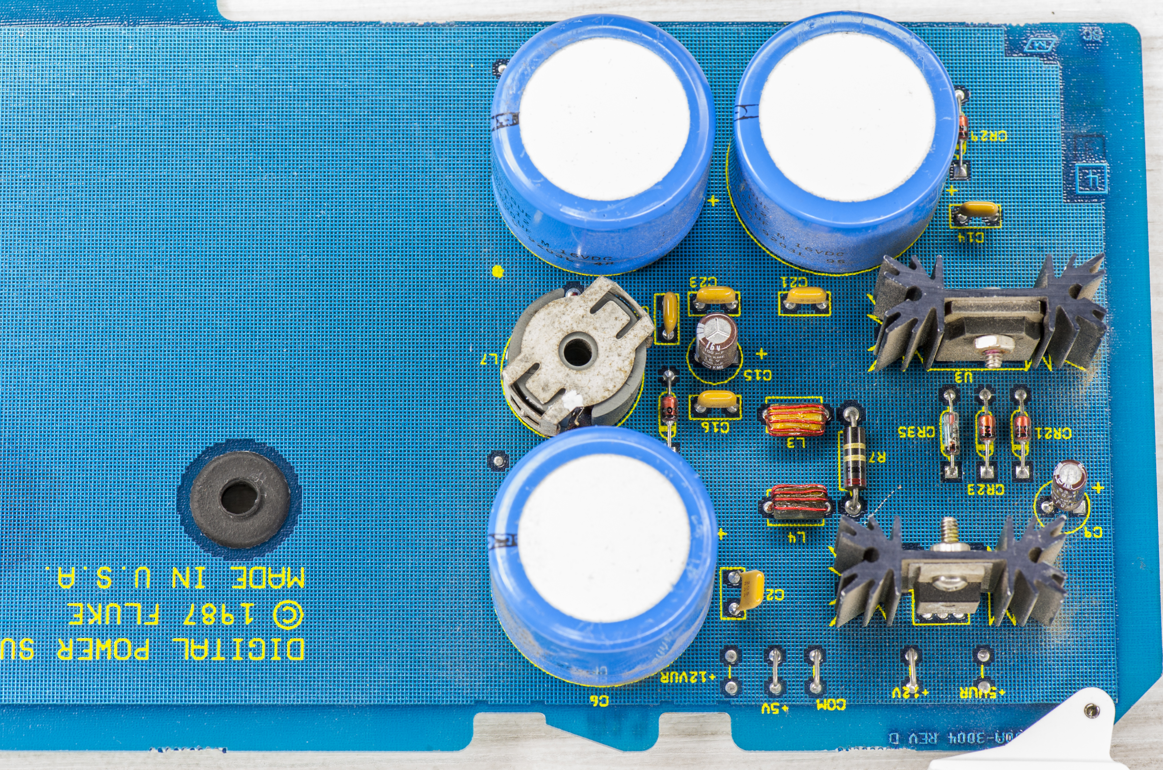
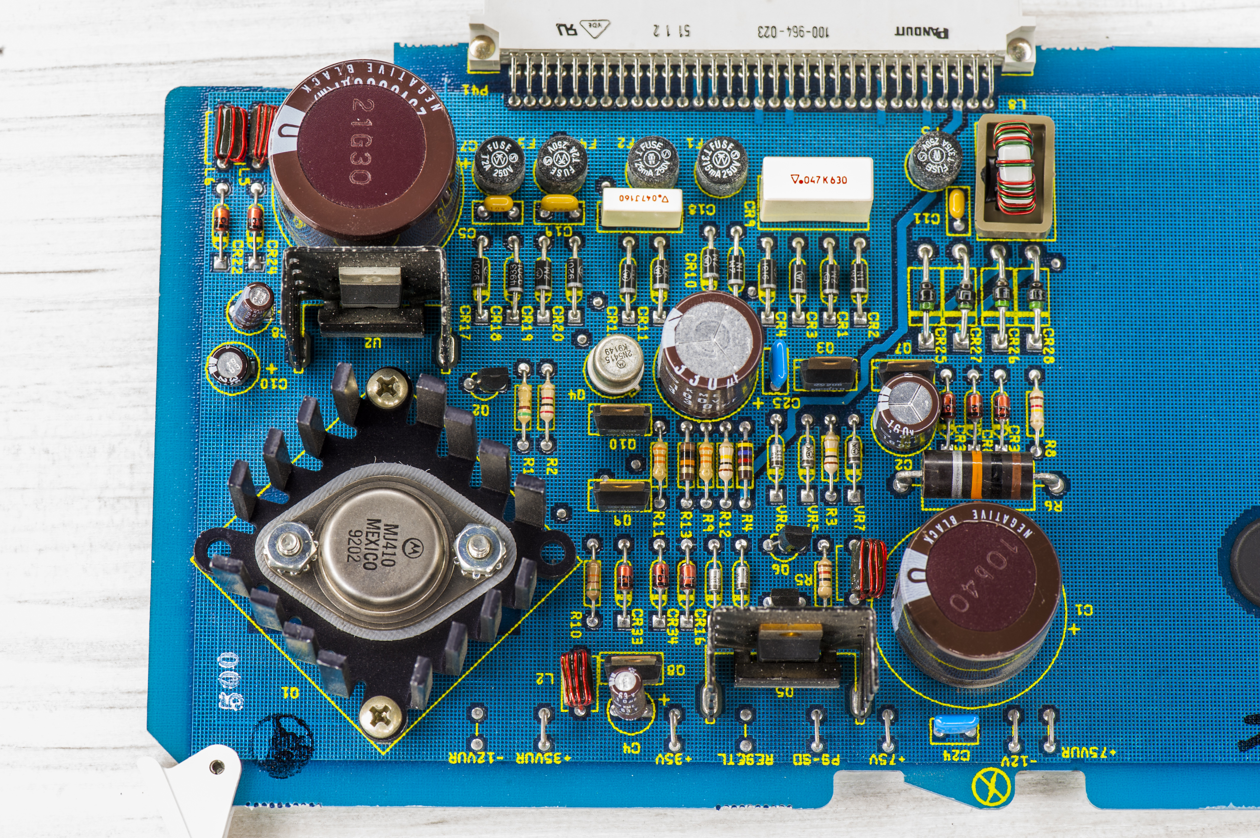
This board had broken L8 pin connection, which was easily fixed by soldering open wire back to PCB. Assembly had all capacitors and carbon composite resistors replaced as preventive maintenance.
A20 outguard 5700A processor board
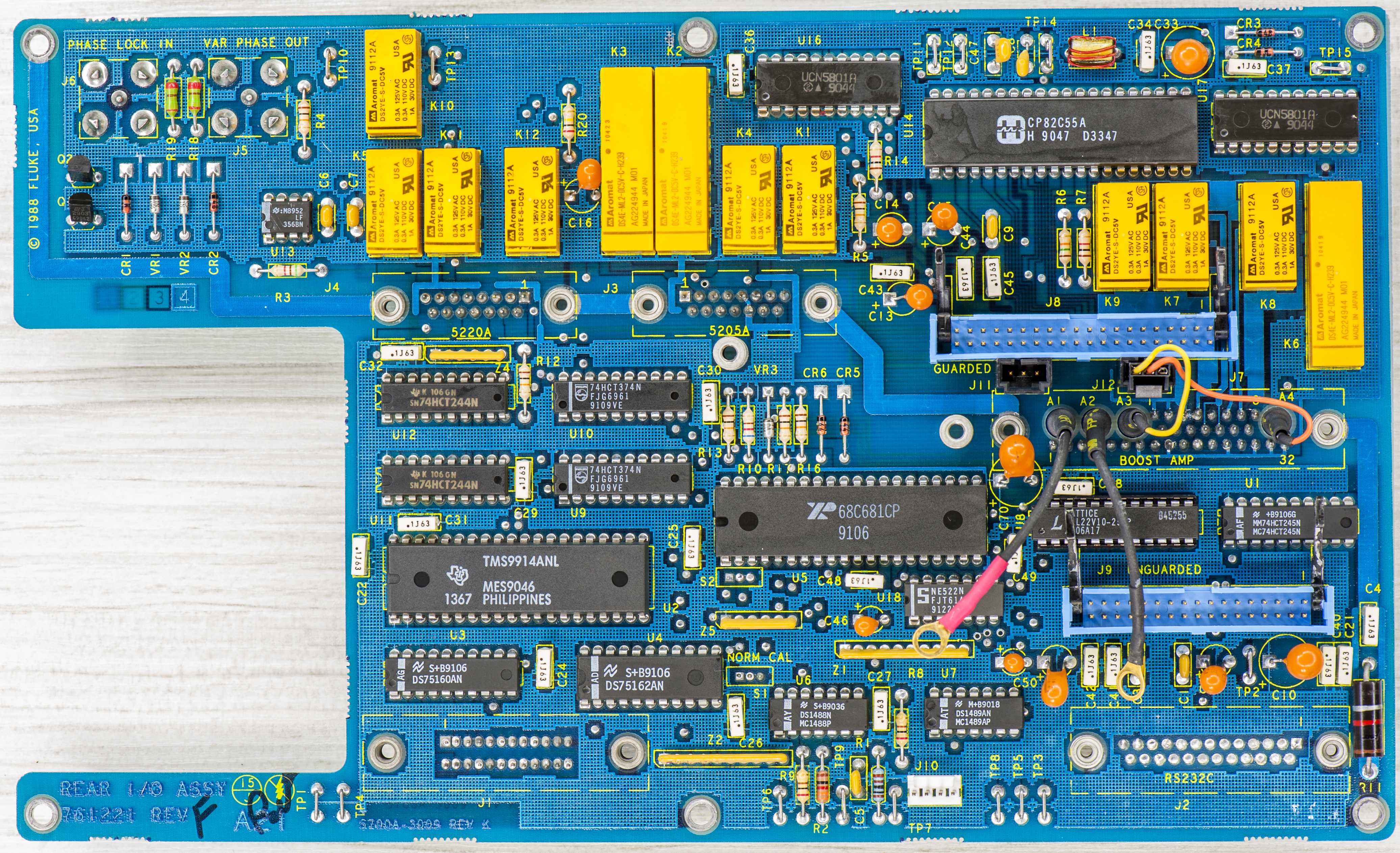
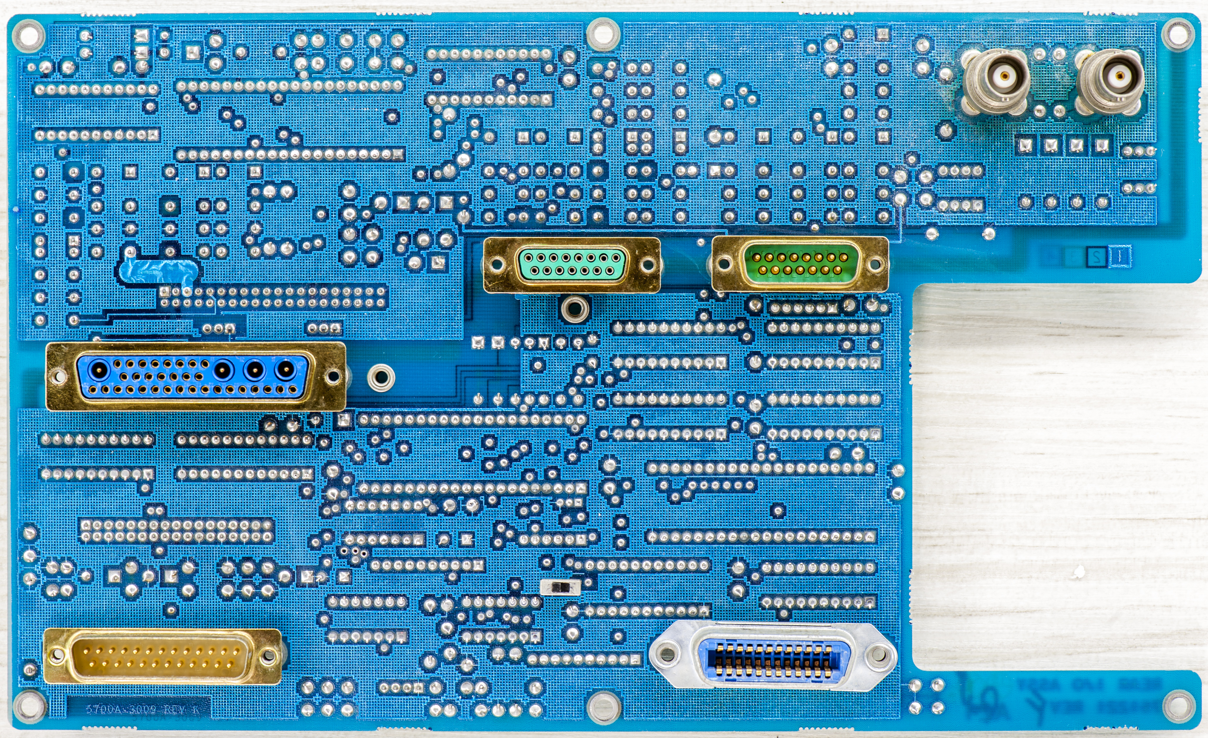
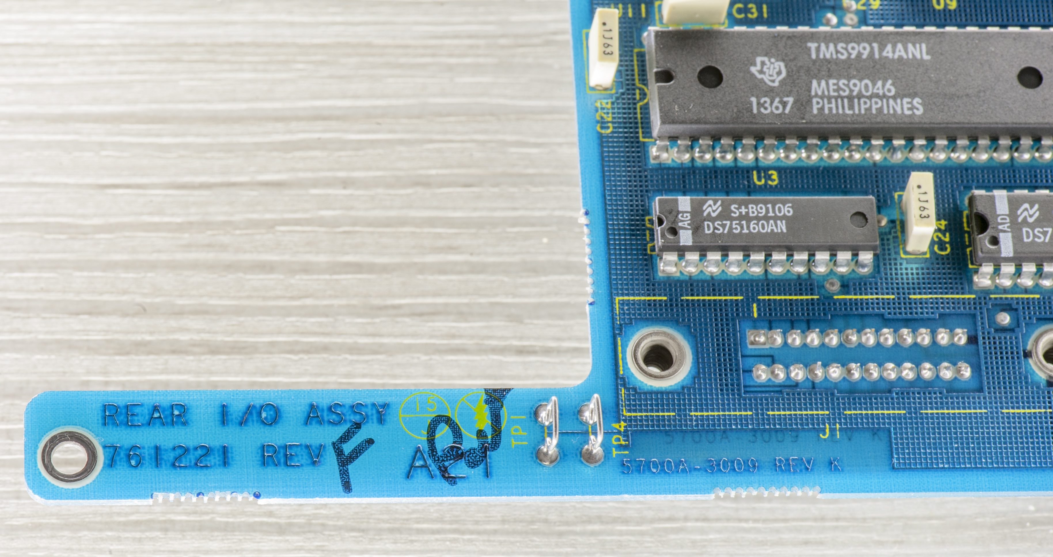
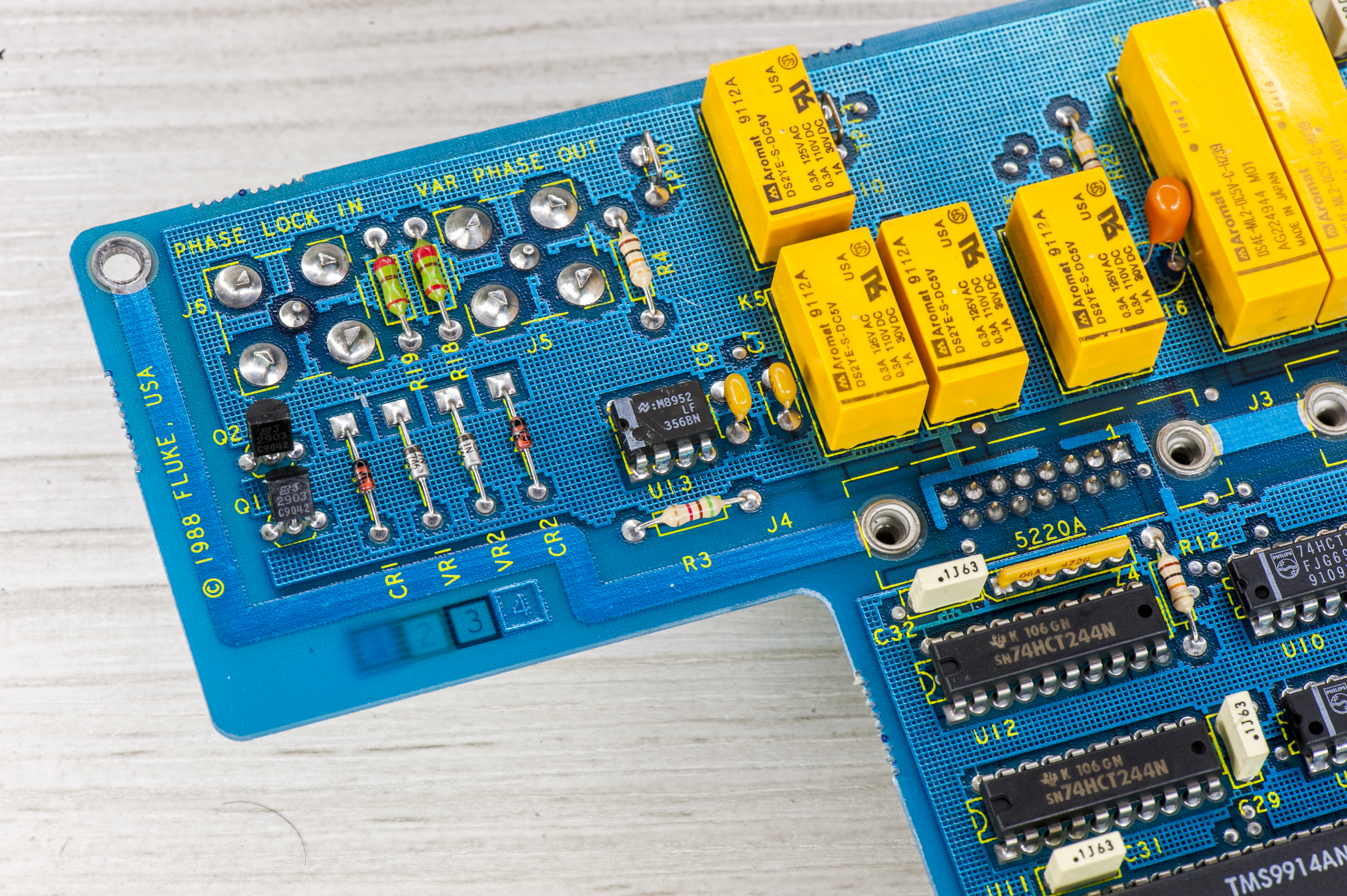
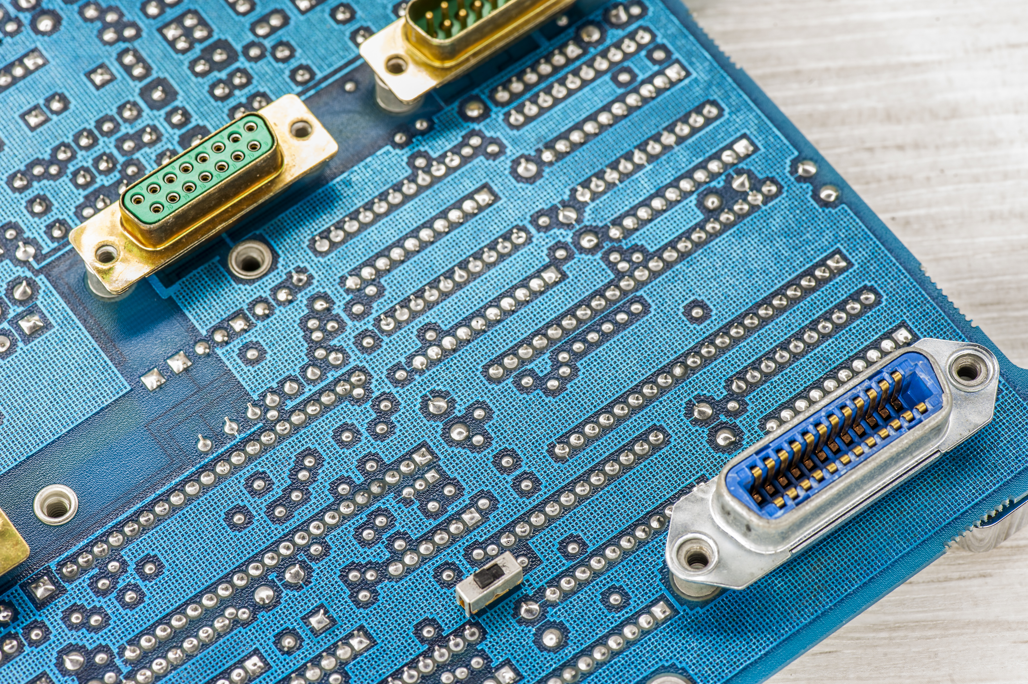
A21 outguard rear I/O board
A18
A17
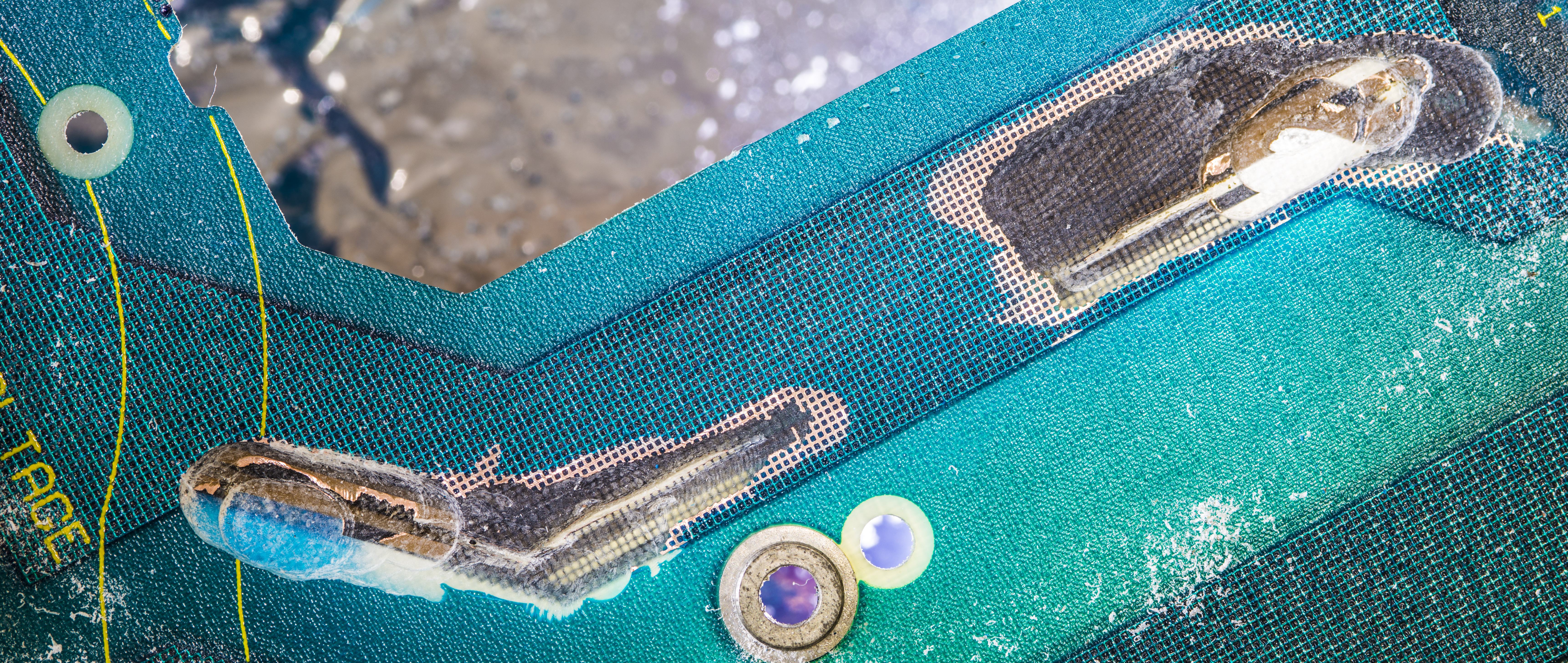
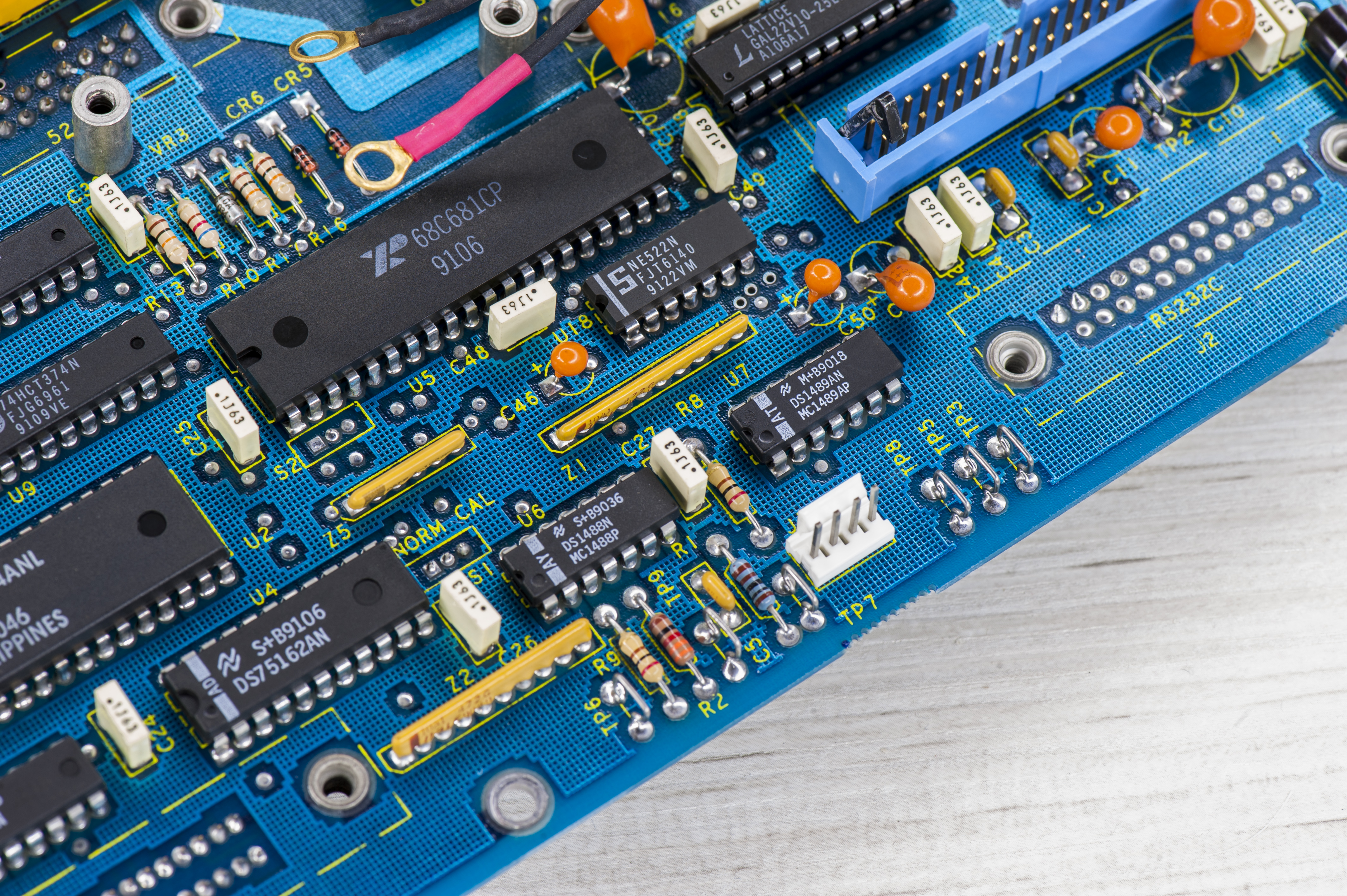
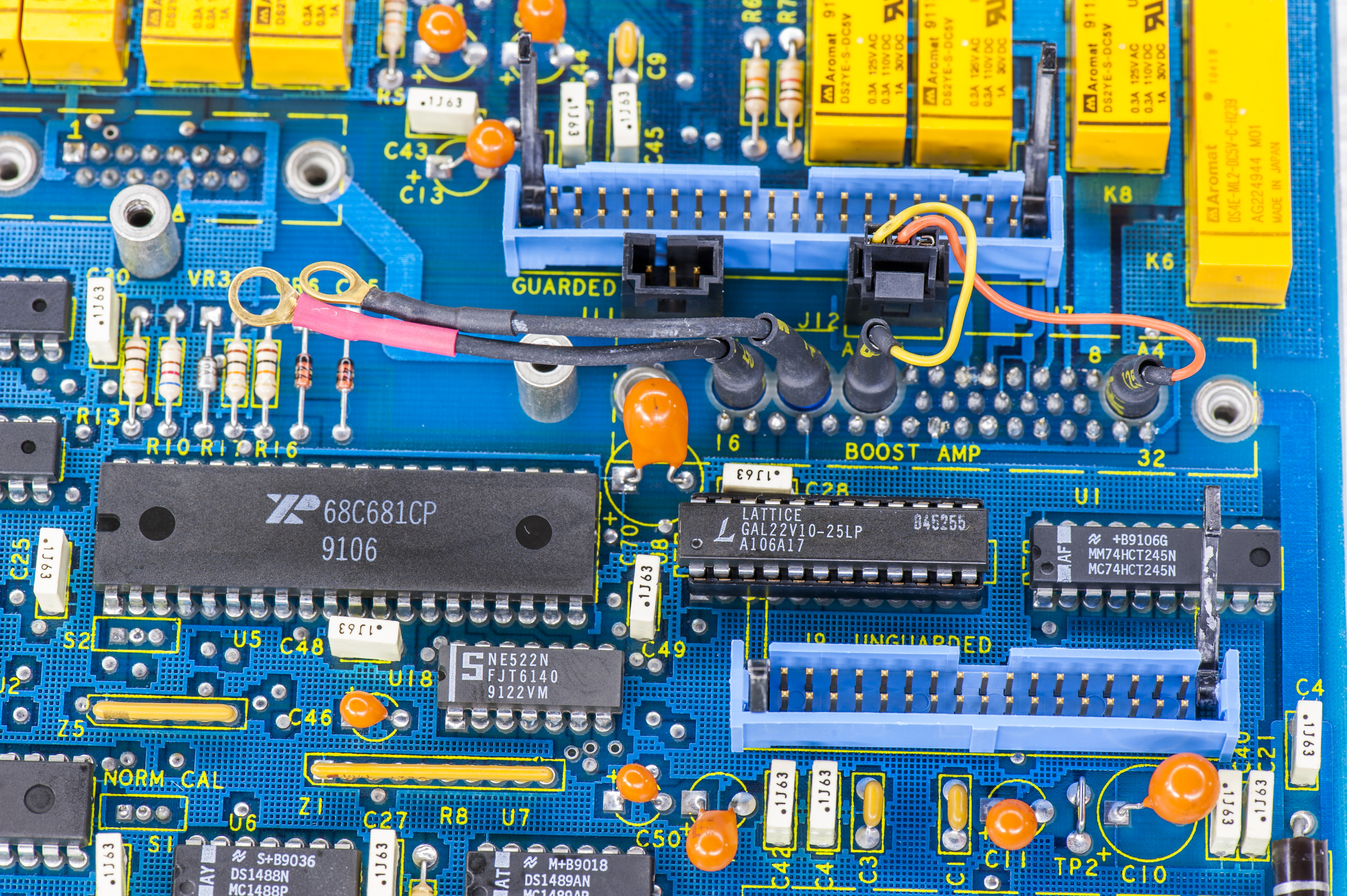
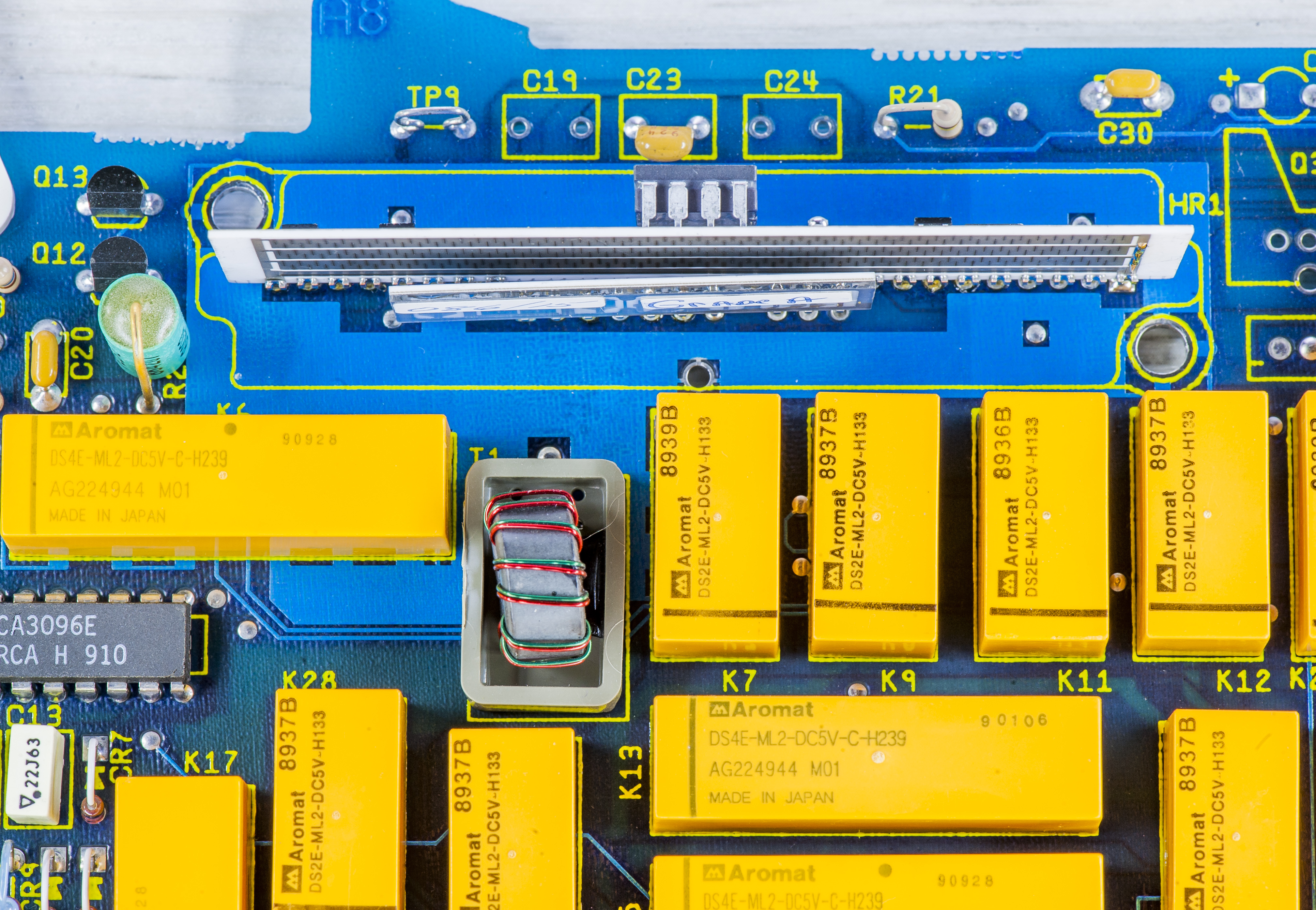
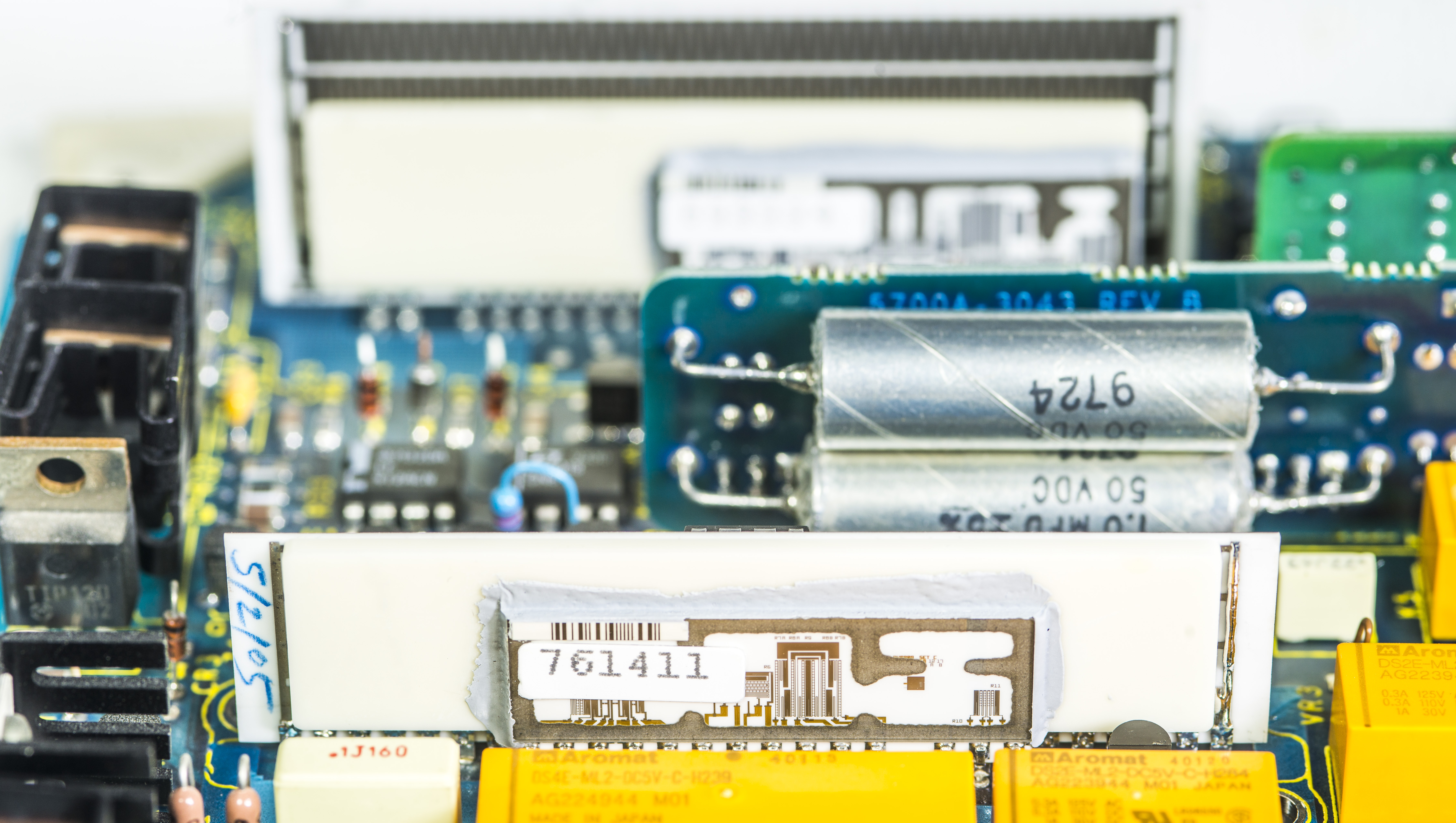
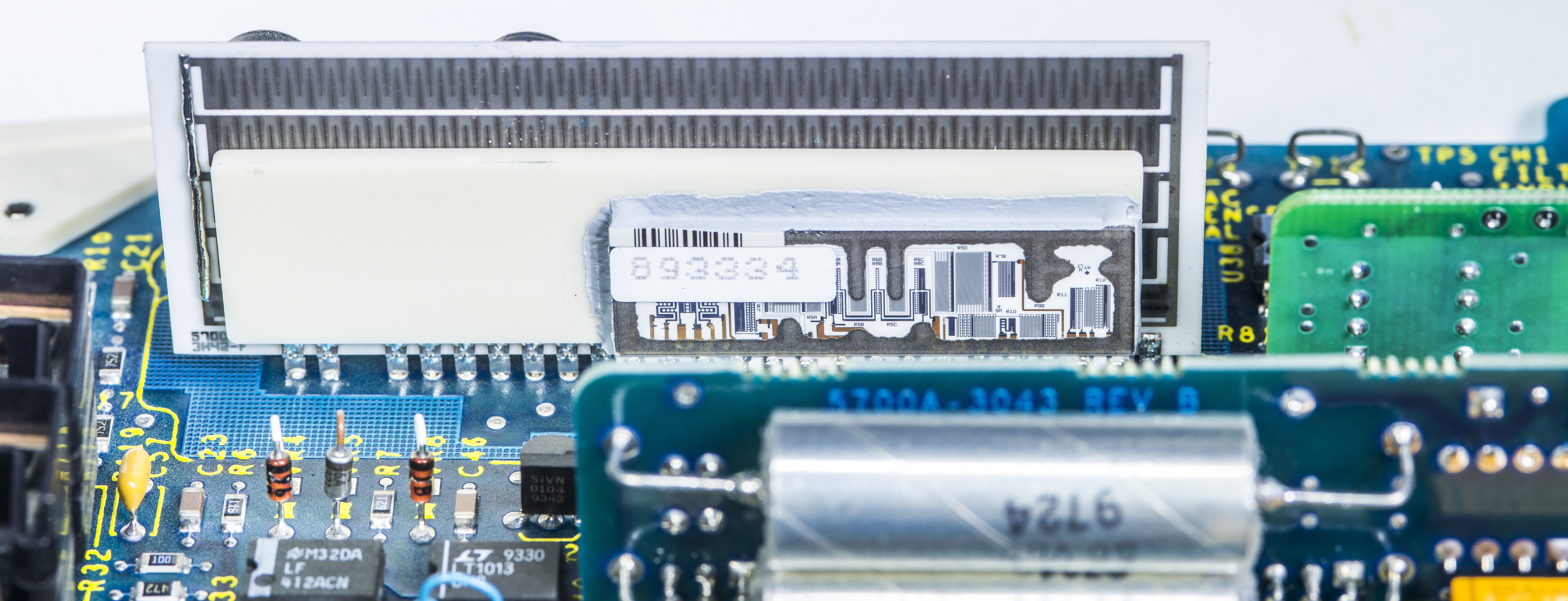
A8 – Switch matrix , 5700A board
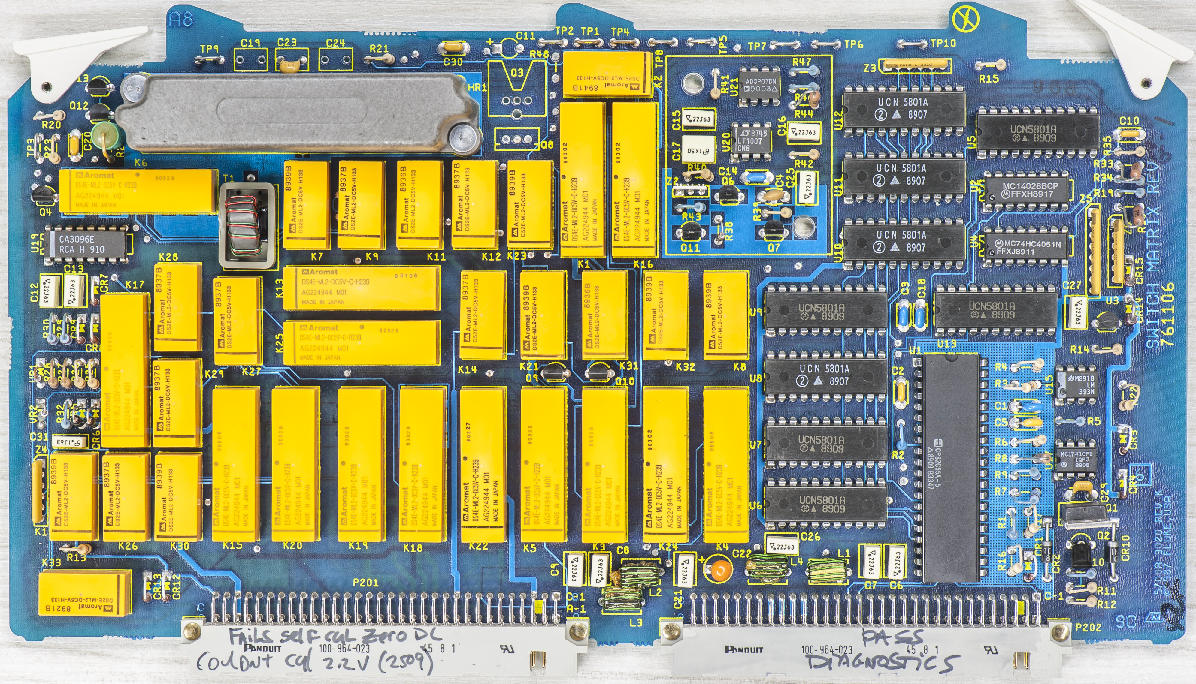
Board made in 1988. Oldie 5700 series I model.
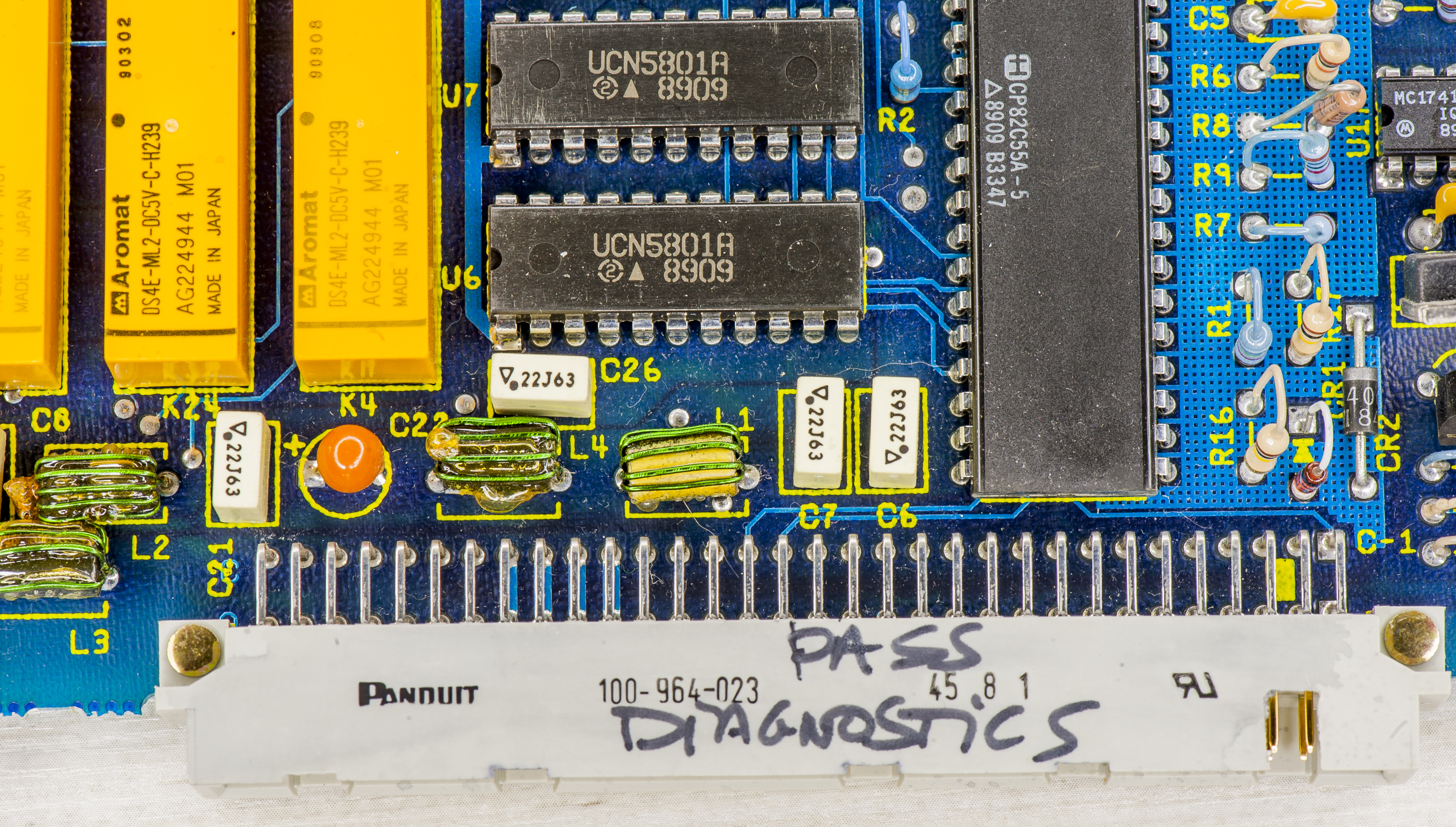
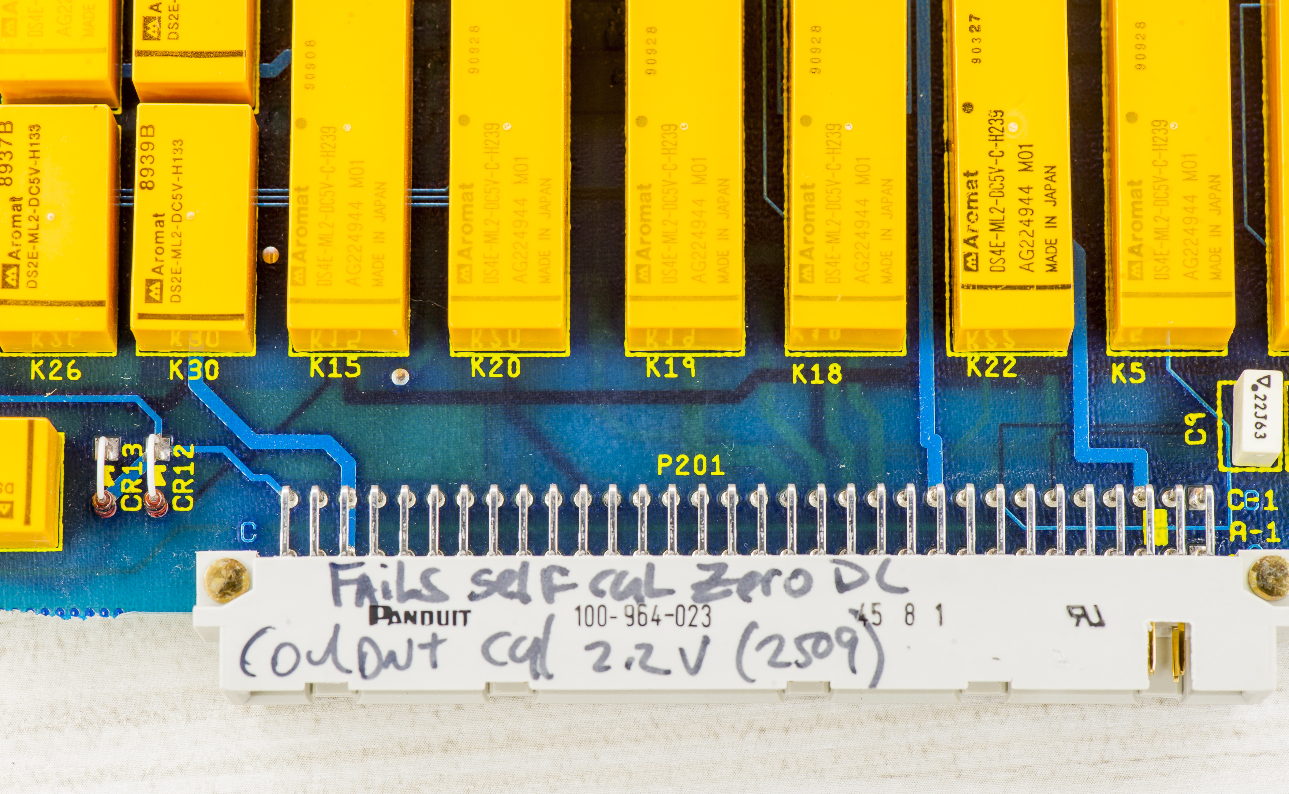
Hmm, I wonder what those labels may mean? Should be nothing, right?

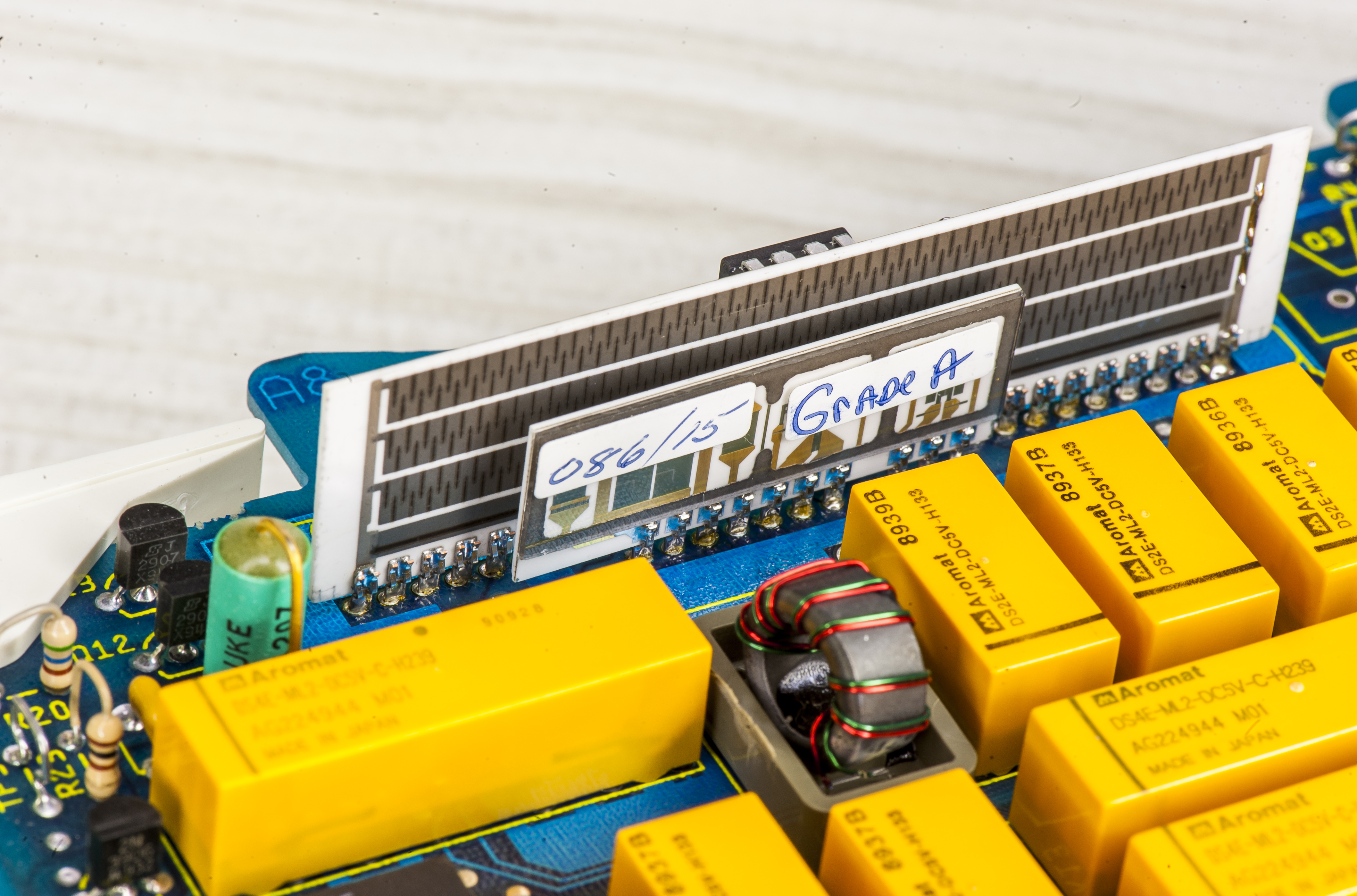
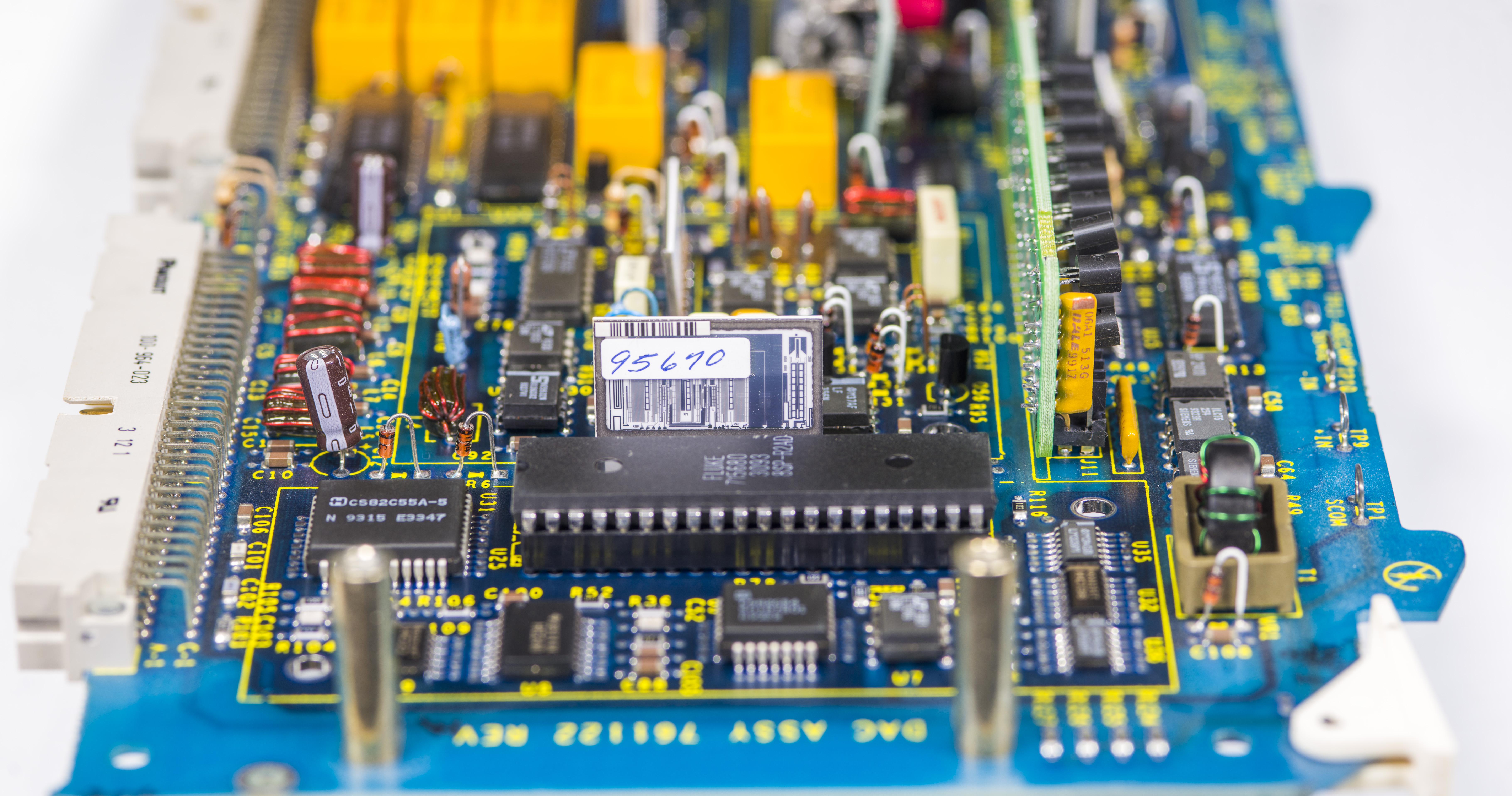
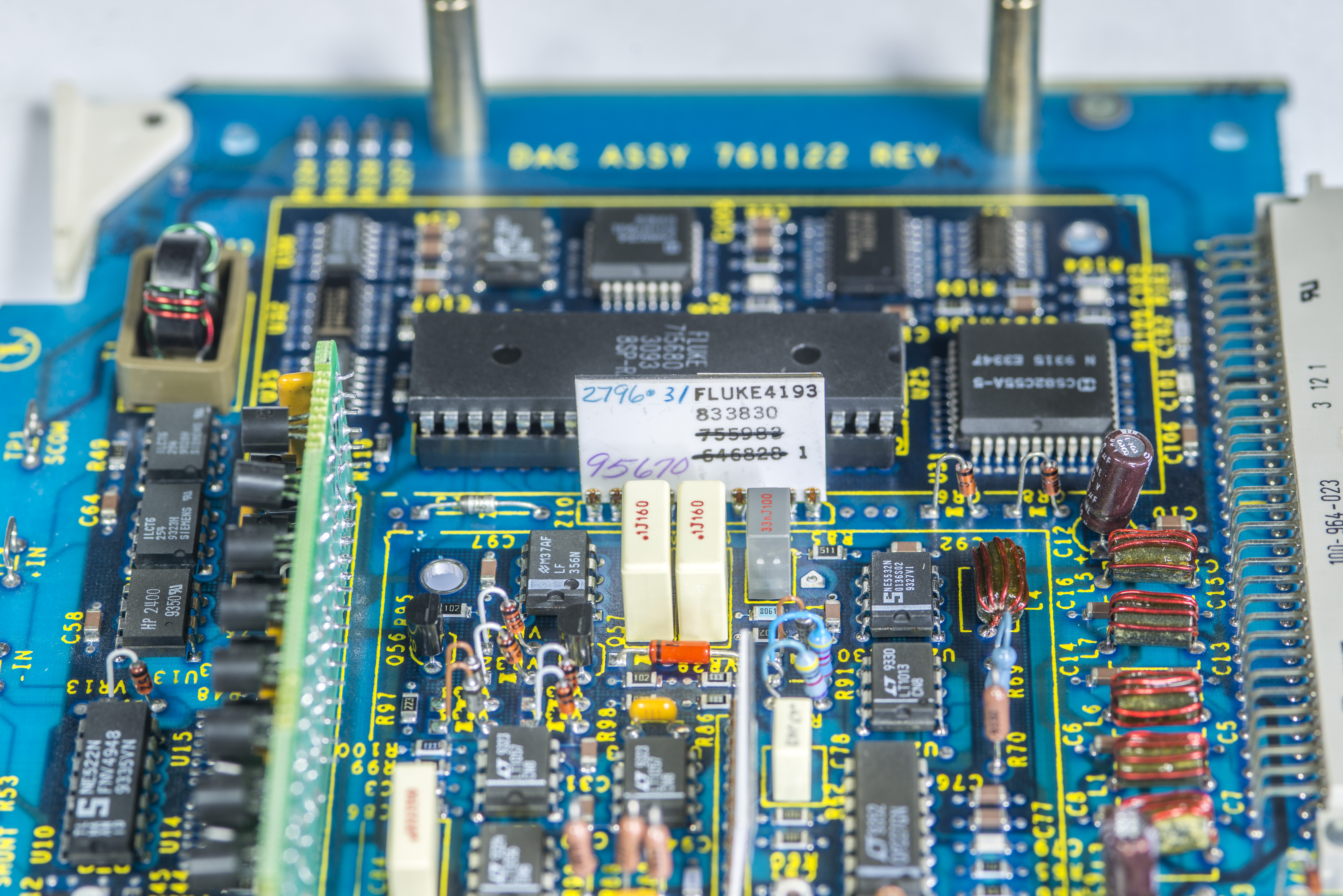
Pretty heater for precision DC amplifier circuit on alumina hybrid module.
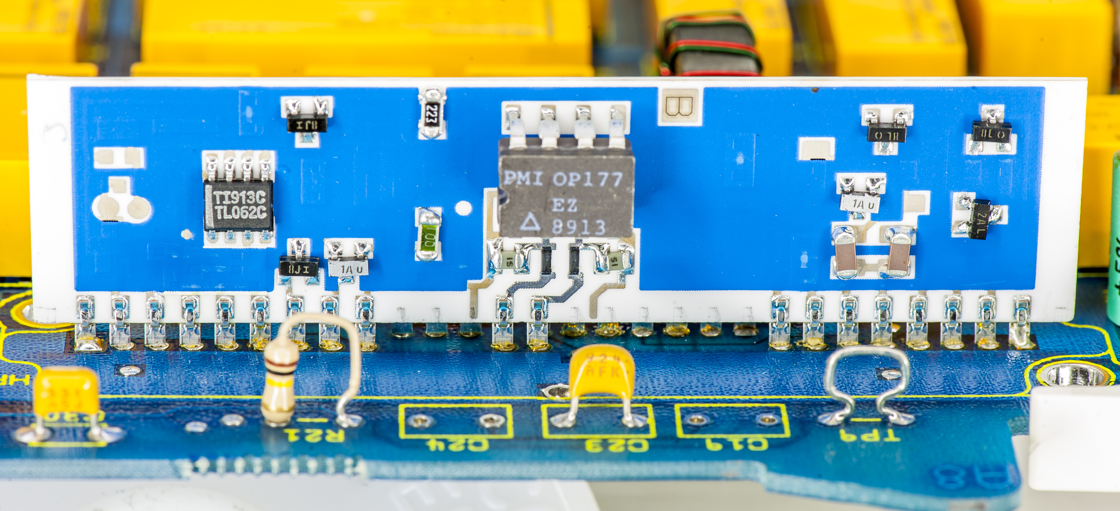
Hermetic OP177EZ from PMI in ceramic DIP8 for DC amplifier circuit. This hybrid works to generate 220mV and 2.2V ranges from 22V range, delivered from DAC A11.

Let’s check heater resistance at the hybrid circuit.
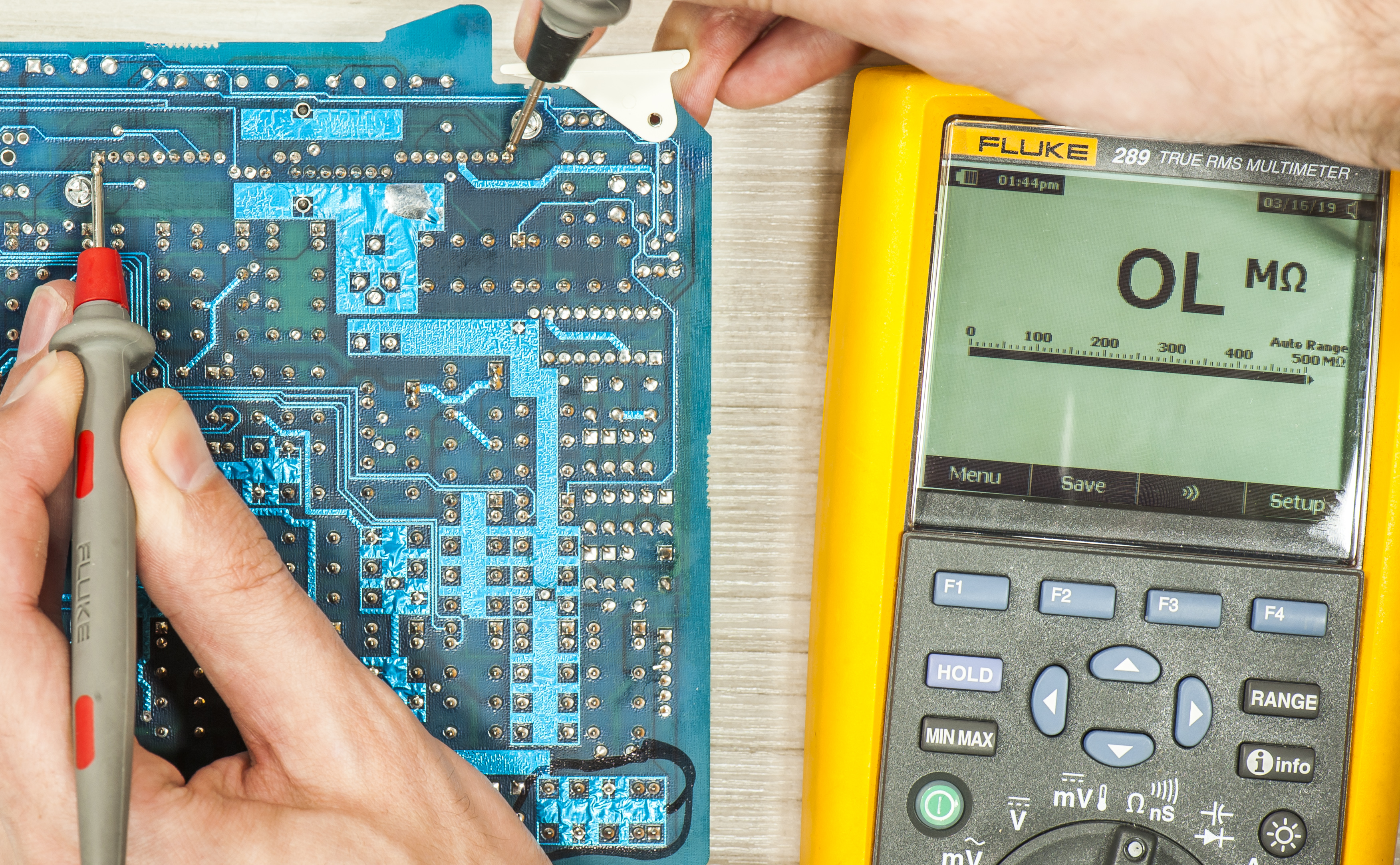
Nooooo….it’s open! Good heater should read around 40-ish Ω.
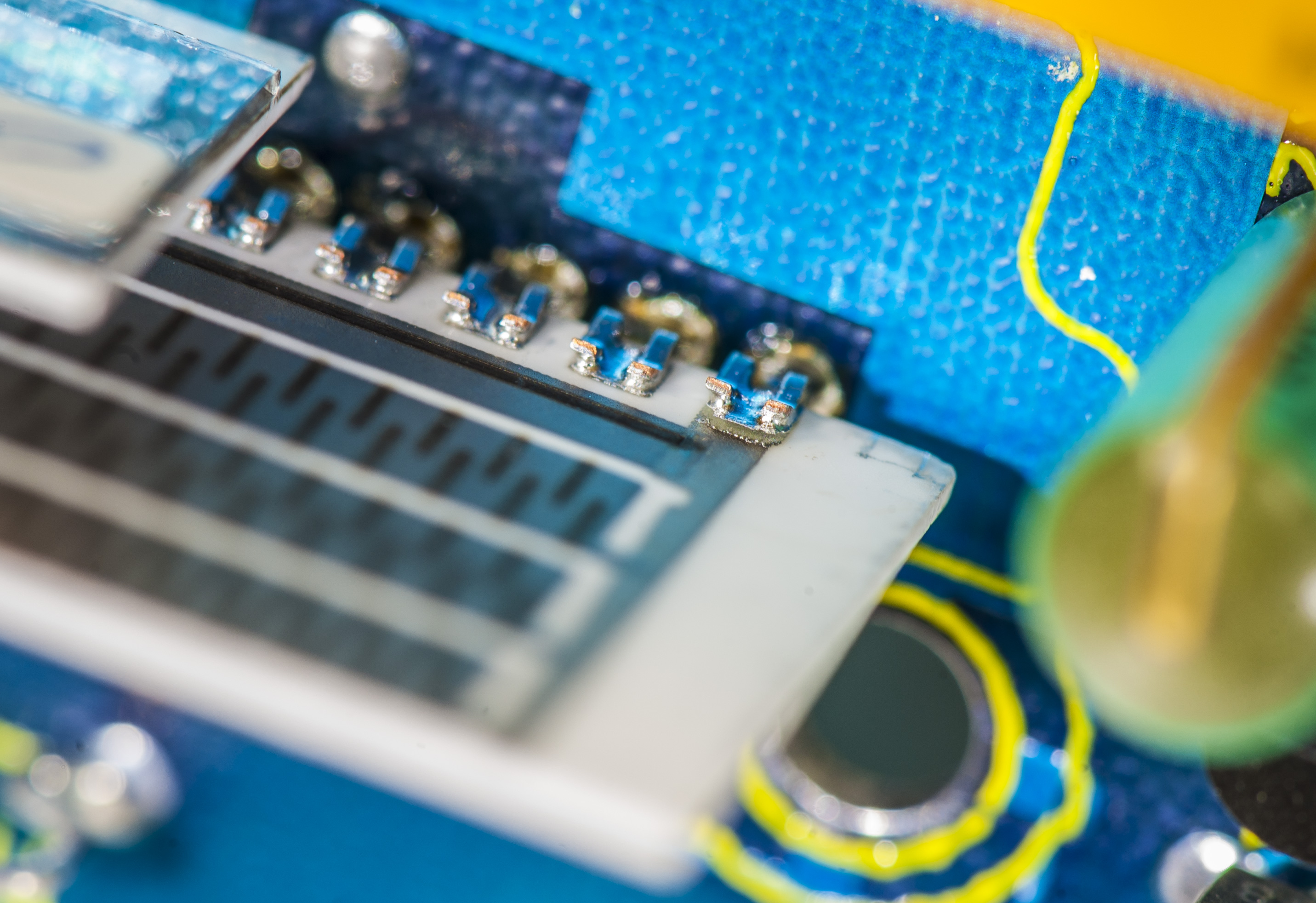
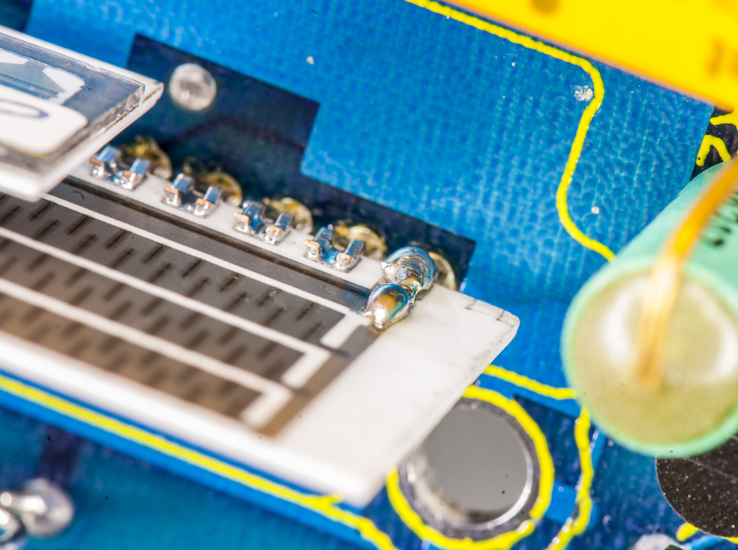
Aha! Left is as received. Right photo after “fix”. :)
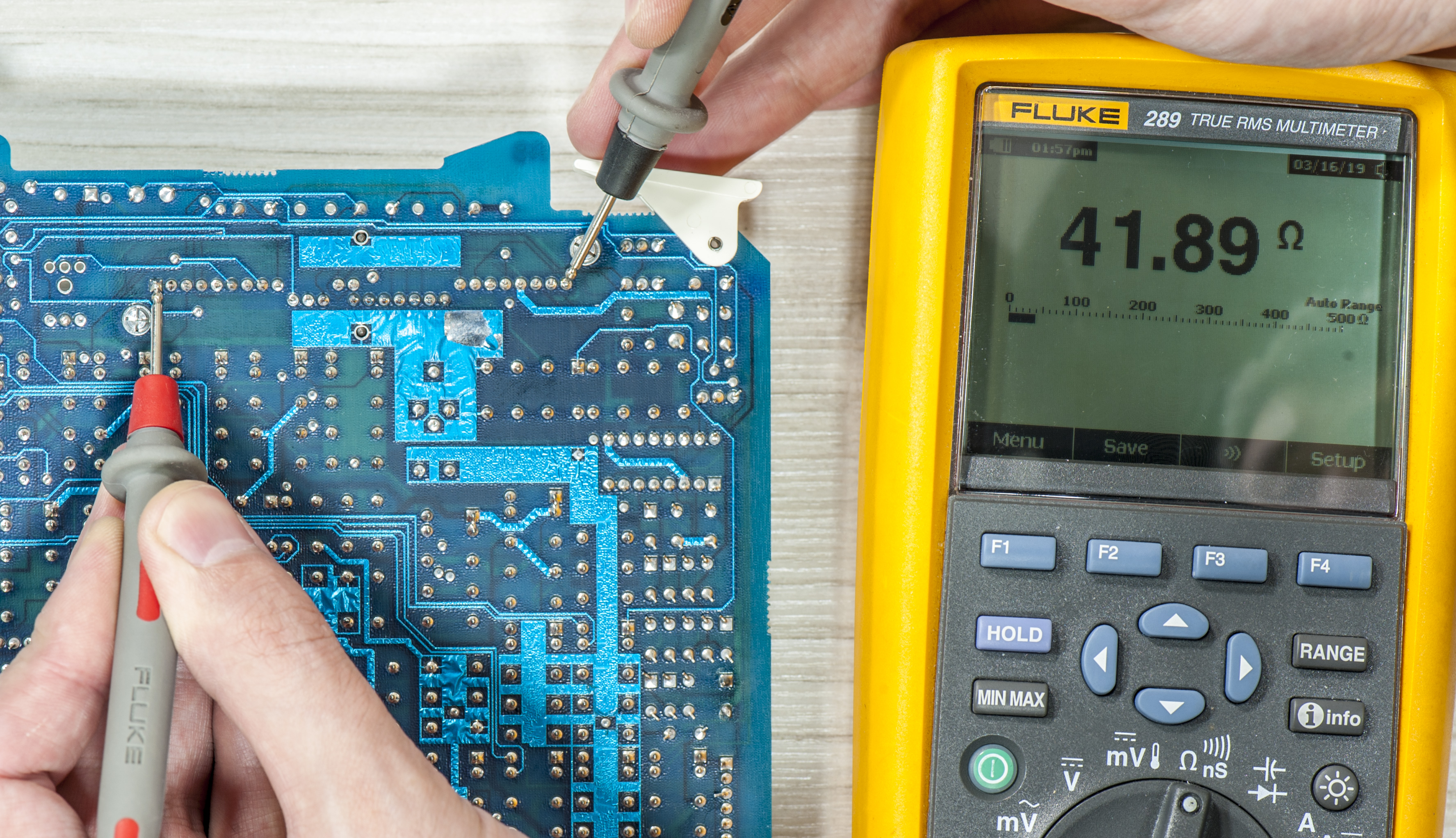
She’ll be alright, no worries!
A11 REF/DAC Model 5720A type board


A9 outguard rear I/O board
A10 outguard rear I/O board
A7 outguard rear I/O board
A12 – Oscillator
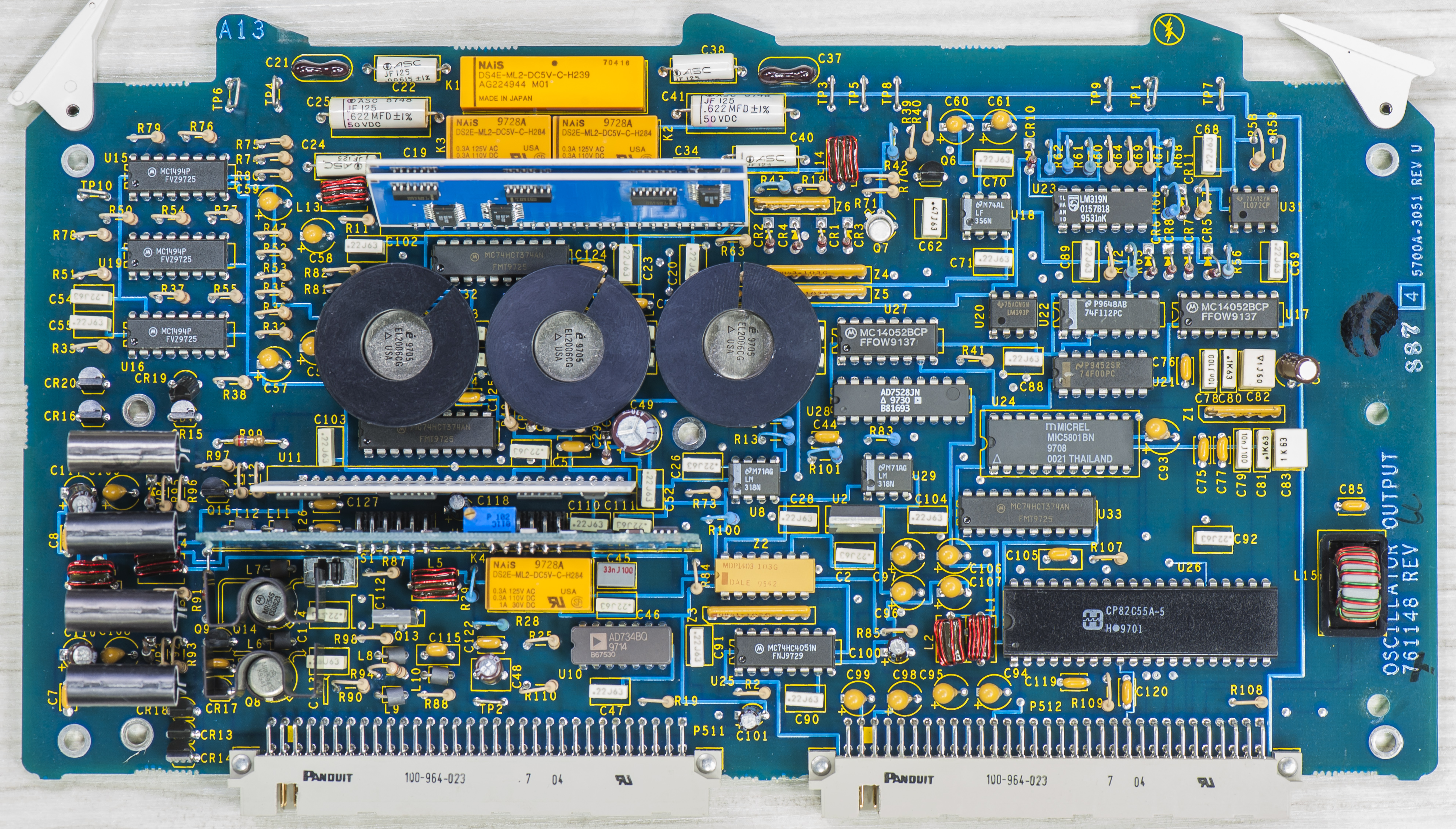
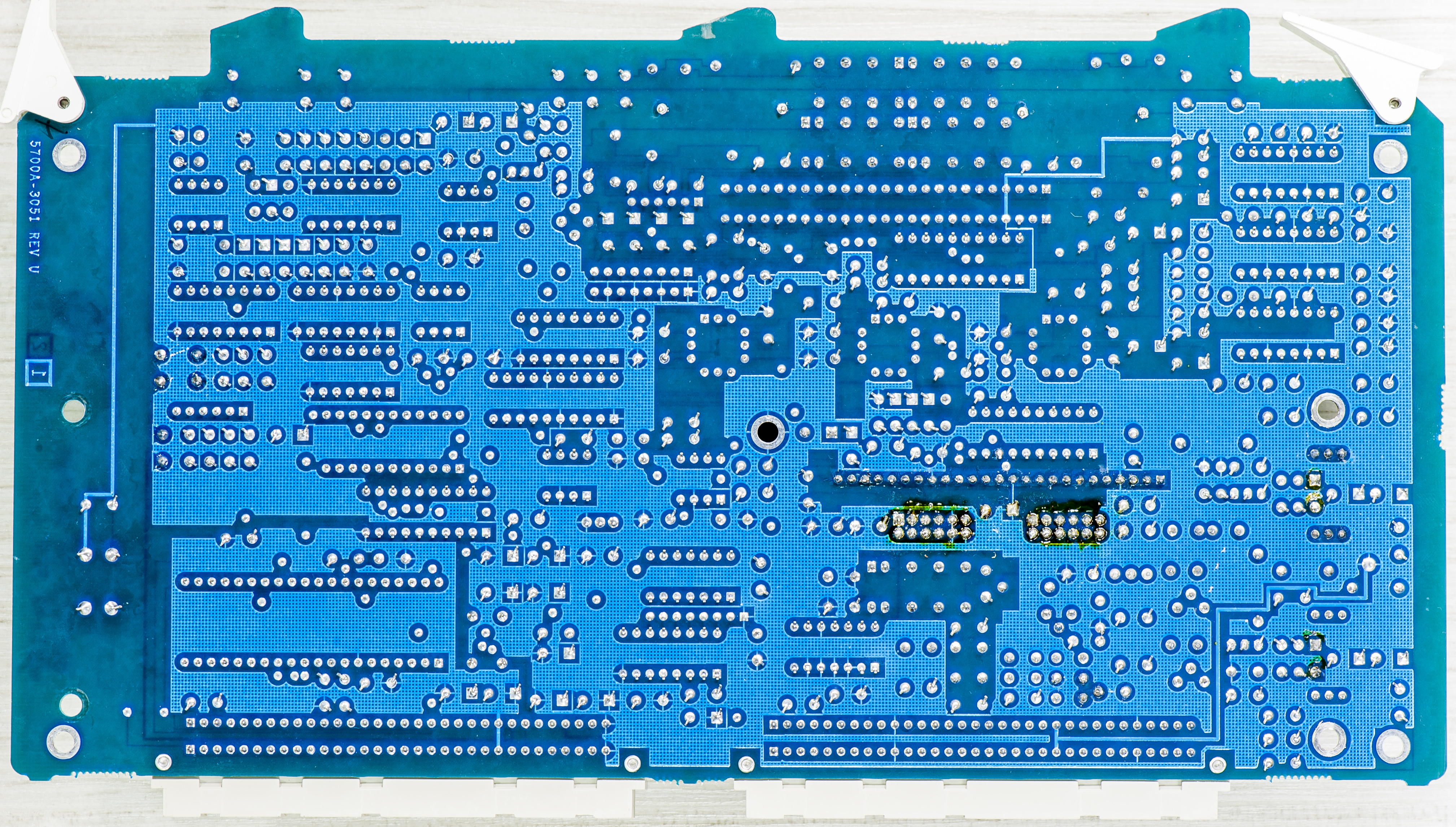
A13 – Oscillator output, 5720A Rev.U board
Summary on spent resources
This project took about $10K USD just in parts, so it does not make financial sense to go down this road. It will be a while till this investment pays for itself, but there are many benefits with 24/7 available multiple 7½ precision calibrators for analog design and various experiments.
And everything started with just innocent buy of 5700A A11 PCBA for $200 to tinker with. Who knew that idea to make stand-alone LTFLU reference get converted into this build? “Volt-nutting” at it’s finest, as even not every calibration lab actually own fully-featured 5720A.
Fortune favors the bold. Perhaps hobbyist with that level of commitment could already buy used and fully working Fluke 5700A, which could need only minor repairs (hopefully). But that was not the goal of this xDevs.com project. It is more interesting to understand (and share via such article) what goes into design of high-performance instrument like Fluke 5700/5720A series multi-function calibrators, with hands-on approach during complex repair tasks.
Discussion about this article and related stuff is very welcome in comment section or at our own IRC-chat server: irc.xdevs.com (standard port 6667, channel: #xDevs.com). Web-interface for access mirrored on this page.
Projects like this are born from passion and a desire to share how things work. Education is the foundation of a healthy society - especially important in today's volatile world. xDevs began as a personal project notepad in Kherson, Ukraine back in 2008 and has grown with support of passionate readers just like you. There are no (and never will be) any ads, sponsors or shareholders behind xDevs.com, just a commitment to inspire and help learning. If you are in a position to help others like us, please consider supporting xDevs.com’s home-country Ukraine in its defense of freedom to speak, freedom to live in peace and freedom to choose their way. You can use official site to support Ukraine – United24 or Help99. Every cent counts.
Modified: April 8, 2021, 5:09 a.m.