- Introduction
- Agilent MXG RF generator series
- Disclaimer
- Manuals and references
- Agilent N5161A ATE MXG unit Exterior
- GUI interface via remote LXI web-page
- Teardown and internal construction
- Repair and BOM list
- Summary and conclusion
Introduction
RF signal generators are keystone instruments for many communication, scientific and engineering laboratories. Ability to generate signals with stable frequency and amplitude as well as various complex modulations is very important in today technical world. There are many series and models of RF generators from simple portable USB units up to very advanced multi-channel millimeter wave instruments that can cost more than a luxury mansion.
Last year we looked at older ESG-DP generator in this article but I always wanted something bit newer for my lab bench. In this article we will look at the mid-range low frequency model from year 2011, MXG ATE N5161A from Keysight Technologies. This instrument was built during Agilent era.
Agilent MXG RF generator series
Current benchtop analog signal generators offered from Keysight are summarized in table below. N5161A we got in the lab this time is older version of MXG RF model with removed front panel and keypad controls, tailored for automated test use in the rack. Internally it is identical to fully user-interfaced N5181A. Current model with B-index in name has updated computer and hardware internally but reuses the same architecture.
| Specifications | UXG | PSG MW | MXG MW | EXG MW | PSG RF | MXG RF | EXG RF | RF |
|---|---|---|---|---|---|---|---|---|
| Model number | N5193A | E8257D | N5183B | N5173B | E8663D | N5181B | N5171B | N9310A |
| Frequency range (min. to max.) | 10 MHz to 40 GHz | 100 kHz to 70 GHz | 9 kHz to 40 GHz | 9 kHz to 40 GHz | 100 kHz to 9 GHz | 9 kHz to 6 GHz | 9 kHz to 6 GHz | 9 kHz to 3 GHz |
| Frequency switching speed | 180 ns | 9 ms | 600 μs | 600 μs | 9 ms | 800 μs | 800 μs | 10 ms |
| Sweep mode | Normal, list, fast CW, streaming | list, step, ramp | list, step | list, step | list, step, ramp | list, step | list, step | list, step |
| Minimum output power at 1 GHz | -80 dBm | -90 dBm | -90 dBm | -90 dBm | -90 dBm | -127 dBm | -110 dBm | -127 dBm |
| Maximum output power at 1 GHz | +10 dBm | +24 dBm | +23 dBm | +23 dBm | +21 dBm | +24 dBm | +21 dBm | +13 dBm |
| Level accuracy at 1 GHz | ±1.5 dB | ± 0.6 dB | ± 0.6 dB | ± 0.6 dB | ± 0.6 dB | ± 0.6 dB | ± 0.6 dB | ± 1.0 dB |
| SSB phase noise at 1 GHz | -144 dBc/Hz (10 kHz offset) | -147 dBc/Hz (10 kHz offset) | -146 dBc/Hz (10 kHz offset) | -122 dBc/Hz (20 kHz offset) | -147 dBc/Hz (10 kHz offset) | -146 dBc/Hz (10 kHz offset) | -122 dBc/Hz (20 kHz offset) | -95 dBc/Hz (20 kHz offset) |
| Harmonics at 1 GHz | -40 dBc | -55 dBc | -33 dBc | -33 dBc | -55 dBc | -35 dBc | -35 dBc | -30 dBc |
| Non-harmonics at 1 GHz | -70 dBc | -80 dBc | -92 dBc | -72 dBc | -80 dBc | -92 dBc | -72 dBc | -50 dBc |
| AM rate | DC to 10 MHz | DC to 100 kHz | DC to 100 kHz | DC to 100 kHz | DC to 100 kHz | DC to 50 kHz | DC to 50 kHz | 20 Hz to 20 kHz |
| Maximum FM deviation | 600 MHz | 128 MHz | 128 MHz | 320 MHz | 16 MHz | 16 MHz | 40 MHz | 100 kHz |
| Maximum PM phase deviation (normal mode) | 12π | 1280 rad | 64 rad | 160 rad | 160 rad | 8 rad | 20 rad | 10 rad |
| Narrow pulse width | 10 ns | 20 ns | 20 ns | 20 ns | 20 ns | 20 ns | 20 ns | 100 μs |
UXG, MXG and EXG series generators also support interfacing Keysight USB power meters which can be very handy for calibration or complicated RF tests and experiments. These generators can be used to generate various protocol signals such as pulse-trains, AM, FM, PM, step/list sweeps. Vector versions of these generators can do most of modern communication protocols as well, such as 5G NR, LTE/LTE-Advanced FDD/TDD, W-CDMA/HSPA+, cdma2000®, GSM/EDGE/Evo, V2X,WLAN 802.11a/b/g/j/p/n/ac/ah/ax,Bluetooth®,IoT (Internet of Things),DFS Radar Profiles, Mobile WiMAX,FM Stereo/RDS, DAB/DAB+/DMB, Land Mobile Radio (LMR), Global Navigation Satellite Systems (GNSS).
Disclaimer
Redistribution and use of this article, any part of it or any images or files referenced in it, in source and binary forms, with or without modification, are permitted provided that the following conditions are met:
- Redistributions of article must retain the above copyright notice, this list of conditions, link to this page (https://xdevs.com/fix/n5161a/) and the following disclaimer.
- Redistributions of files in binary form must reproduce the above copyright notice, this list of conditions, link to this page (https://xdevs.com/fix/n5161a/), and the following disclaimer in the documentation and/or other materials provided with the distribution, for example Readme file.
All information posted here is hosted just for education purposes and provided AS IS. In no event shall the author, Keysight Technologies, xDevs.com site or any other 3rd party be liable for any special, direct, indirect, or consequential damages or any damages whatsoever resulting from loss of use, data or profits, whether in an action of contract, negligence or other tortuous action, arising out of or in connection with the use or performance of information published here.
If you are willing to contribute or add your experience regarding instrument repairs or provide extra information, you can do so following these simple instructions.
Certain commercial equipment, instruments, or materials are identified in this article to foster better understanding. Such identification does not imply recommendation or endorsement by the author or/and xDevs.com, nor does it imply that the materials or equipment identified are necessarily the best available for the purpose. Devices and components were not screened or conditioned prior to use in the electronic assembly, unless explicitly stated otherwise.
Manuals and references
Agilent N5161A/62A/81A/82A/83A MXG Signal Generators SCPI command reference
Agilent Technologies N5161A/62A/81A/82A/83A MXG Signal Generators Service Guide
Calibration certificate report for this N5161A MY50142531 unit
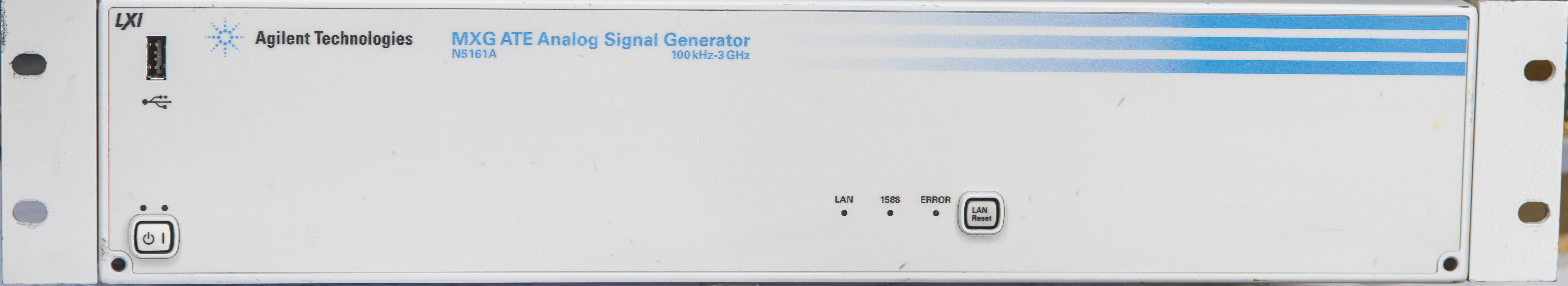
Agilent N5161A ATE MXG unit Exterior
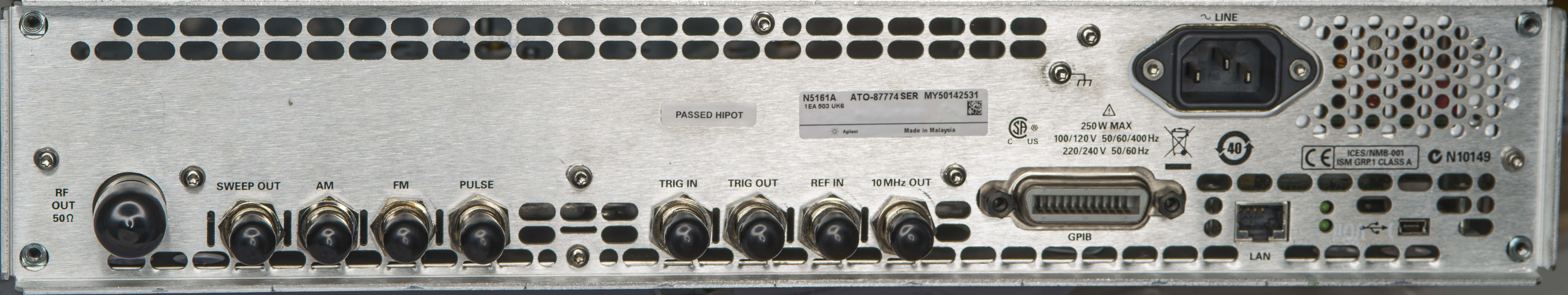
ATE version of MXG generators using same internal hardware for signal generation but lacks the fancy LCD front-panel and keypad. Only way to interface the instrument is via remote connection from computer. There are two interfaces available – nice LXI-compatible Ethernet RJ45 port and good old IEEE-488 GPIB.
RF output on N5161A is also available only at the rear with N-type connector. Front side only has power button with power LED indicators (standby orange and green powered on), three status LEDs (LAN activity, 1588 activity and ERROR fault LED indicator). There is LAN Reset button to revert the settings. USB port is available for data transfer and for connections with external USB Power sensors, such as Keysight U2000 series.
Rear side has mains power entry IEC C14 receptacle, row of BNC connectors for auxilary signals such as reference input and output, triggering, modulation. unmarked Mini-USB is also available but it’s only for factory use by Keysight, likely to program and configure CPU.
To open up the instrument we need remove the side handle and rear bumpers. That will release the metal cover to slide off the back.
GUI interface via remote LXI web-page
This generator received with description – broken power supply. Funny enough I had the instrument to power up first time and was quite puzzled that it worked and passed all self-tests and checks, running for few hours.
Connecting to instrument was super-easy. Just power the unit on, find it’s IP and go to it with a standard web-browser. You get welcome screen to LXI instrument:
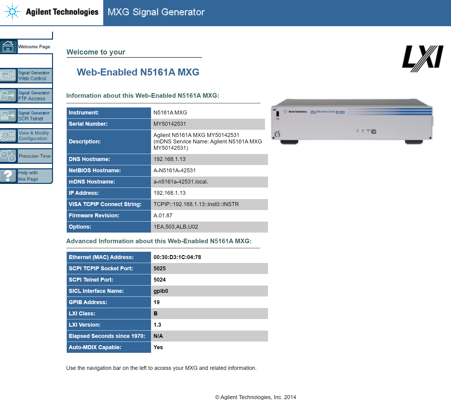
Web control tab opens up pop-up window with actual GUI of the generator after entering default password ‘agilent’. There we can “press” buttons and control all aspects of the instruments from the GUI. Obviously all the functionality is also available via programming SCPI interface. This N5161A is also equipped with LXI Class B compatiblity option.
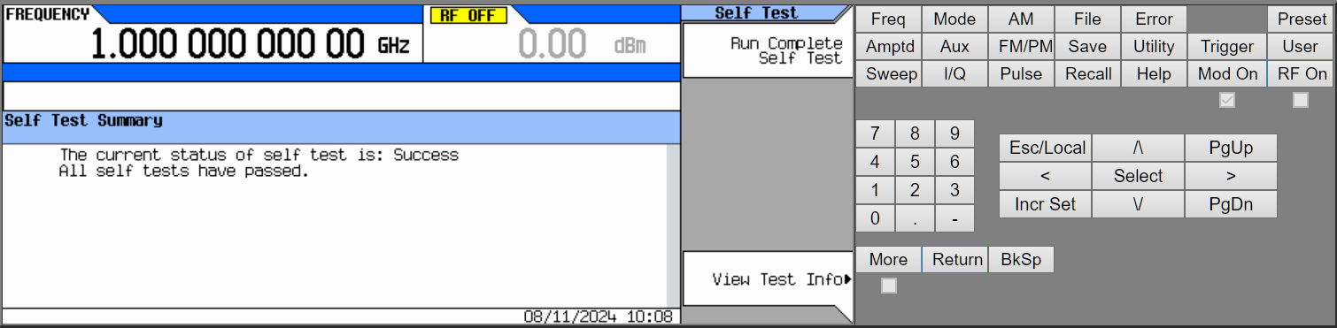
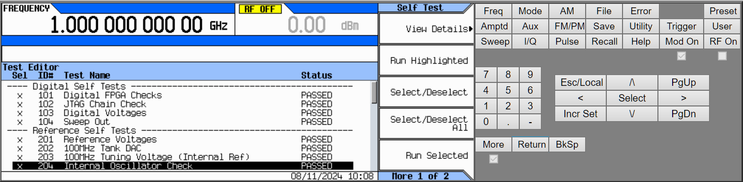
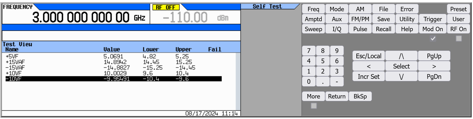
I’ve ran full self-test which passed after few minutes. Each self-test item can be further checked for expected and measured values.
We can also check MXG information page as well.
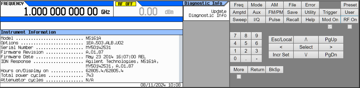
It is already running latest available A.01.87 firmware from May 23, 2014. This generator has 62803.7 hours powered on and 743 power cycles, so it had seen some use.
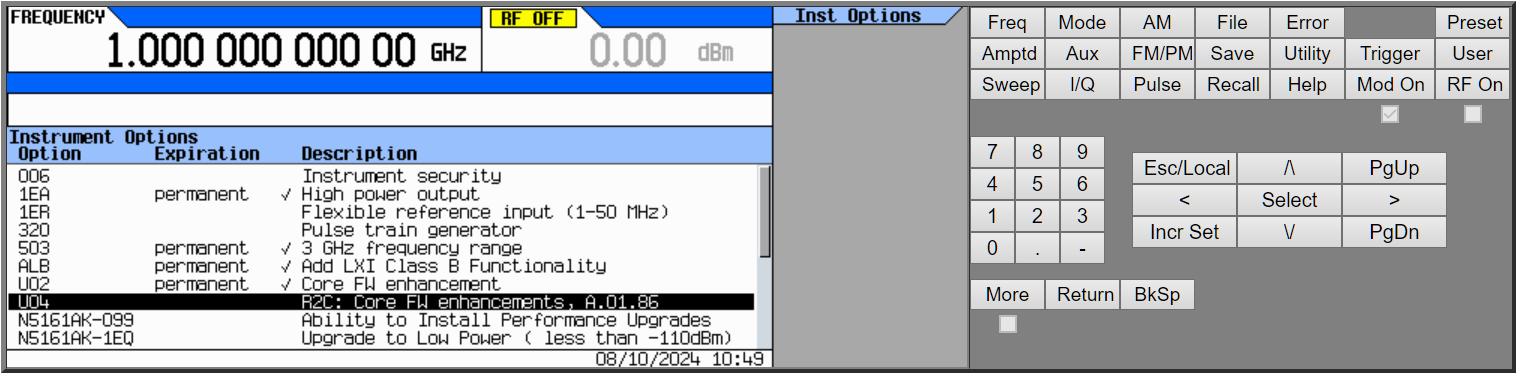
Installed options are:
- 1EA – High power output. This generator can go up to +26 dBm at maximum 3 GHz frequency.
- 503 – 3 GHz output frequency range
- ALB – LXI Class B functionality added
- U02 – Core firmware enhancment
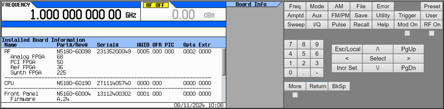
We can also check some boards information too.
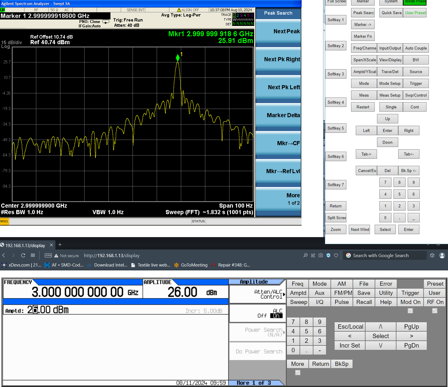
I’ve also connected to my LXI-compatible N9020A 3.6 GHz RF spectrum analyzer and ran phase-noise measurement at 850 MHz frequency output of this N5161A. It looked good, but I have no deep understanding of RF performance figures to judge it to other offerings on the market. xDevs.com is mostly focused on DC and resistance stuff, and some AC ppms below 1 MHz :-)

High power option can be useful for testing in the lab, and this MXG with 1EA option can go up to +30 dBm but actually levelled output works up to +26 dBm with maximum 3000 MHz output frequency. at 1000 MHz it can do about +27 dBm.
After capturing these screenshots I’ve powered down and disassembled the instrument to take our traditional teardown photos. All done with careful removal of the mainboard shield cover, wearing ESD-strap and usual electronics assembly handling precautions.
However after reassembly and setting it up on desired spot in the lab this MXG ATE refused to power up. Just got quickly blinking orange LED near power switch. This is often a telltale of faulty switch-mode power supply that trying to start up and failing. Second teardown and power supply investigation now.
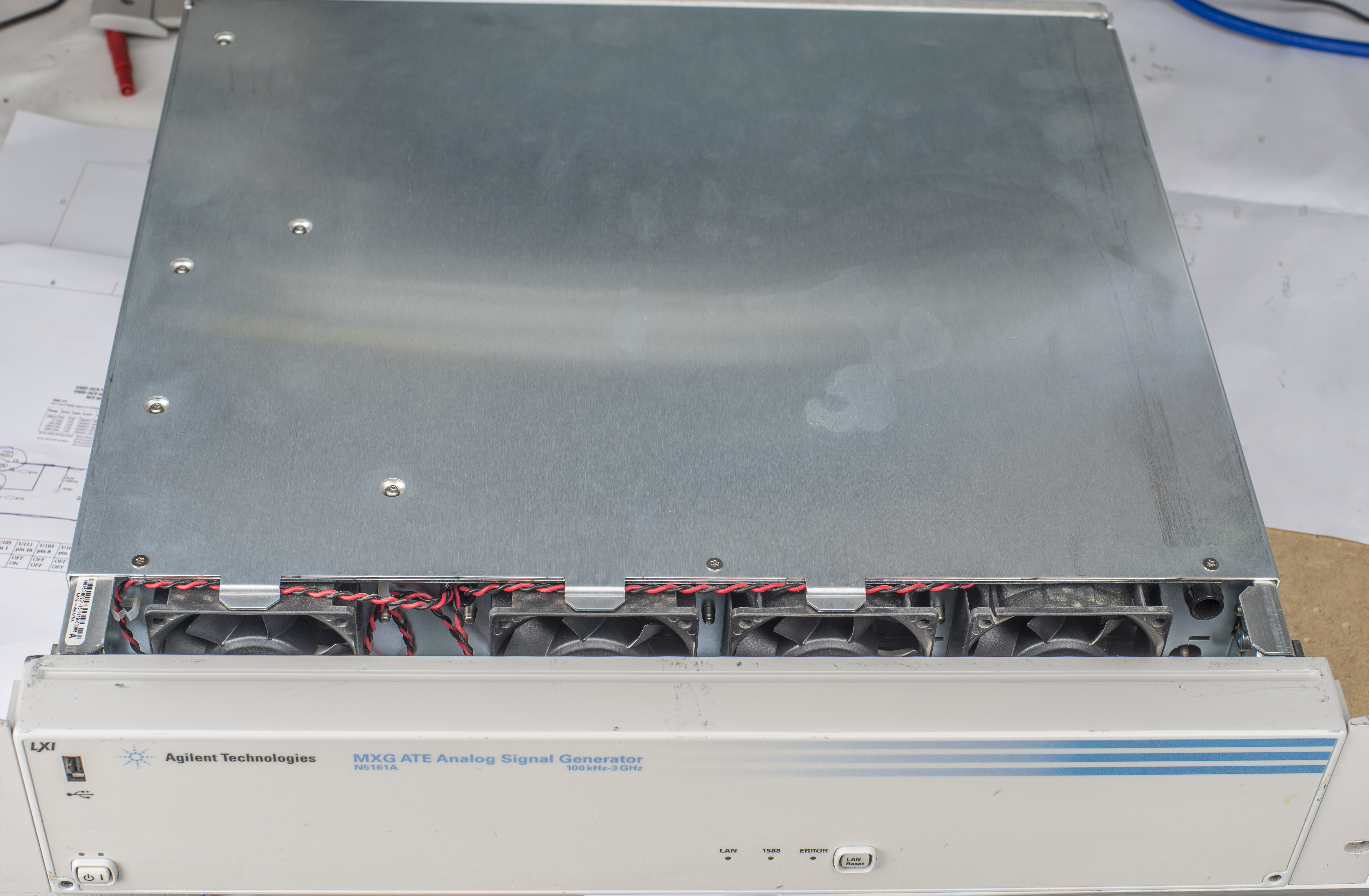
Teardown and internal construction
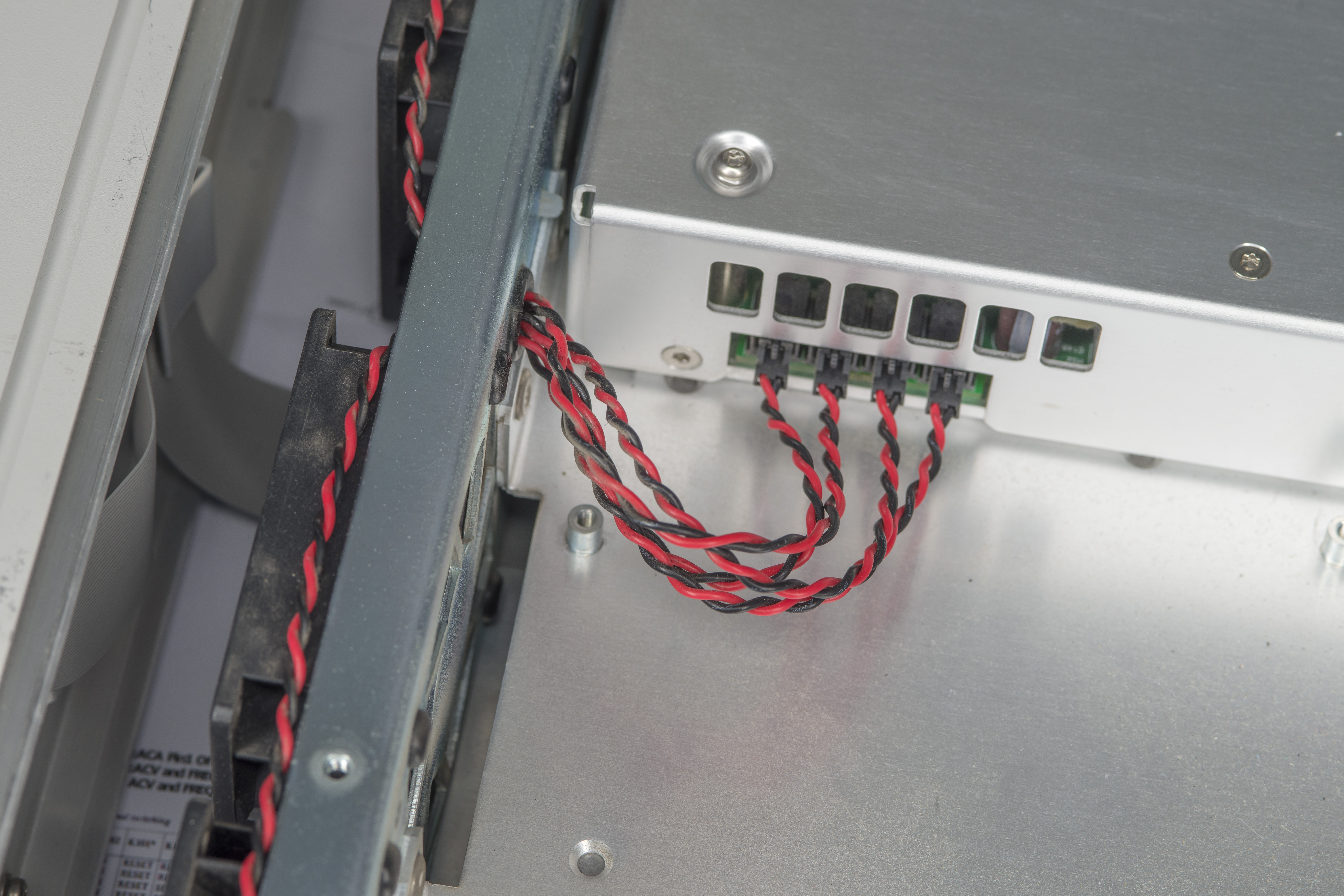
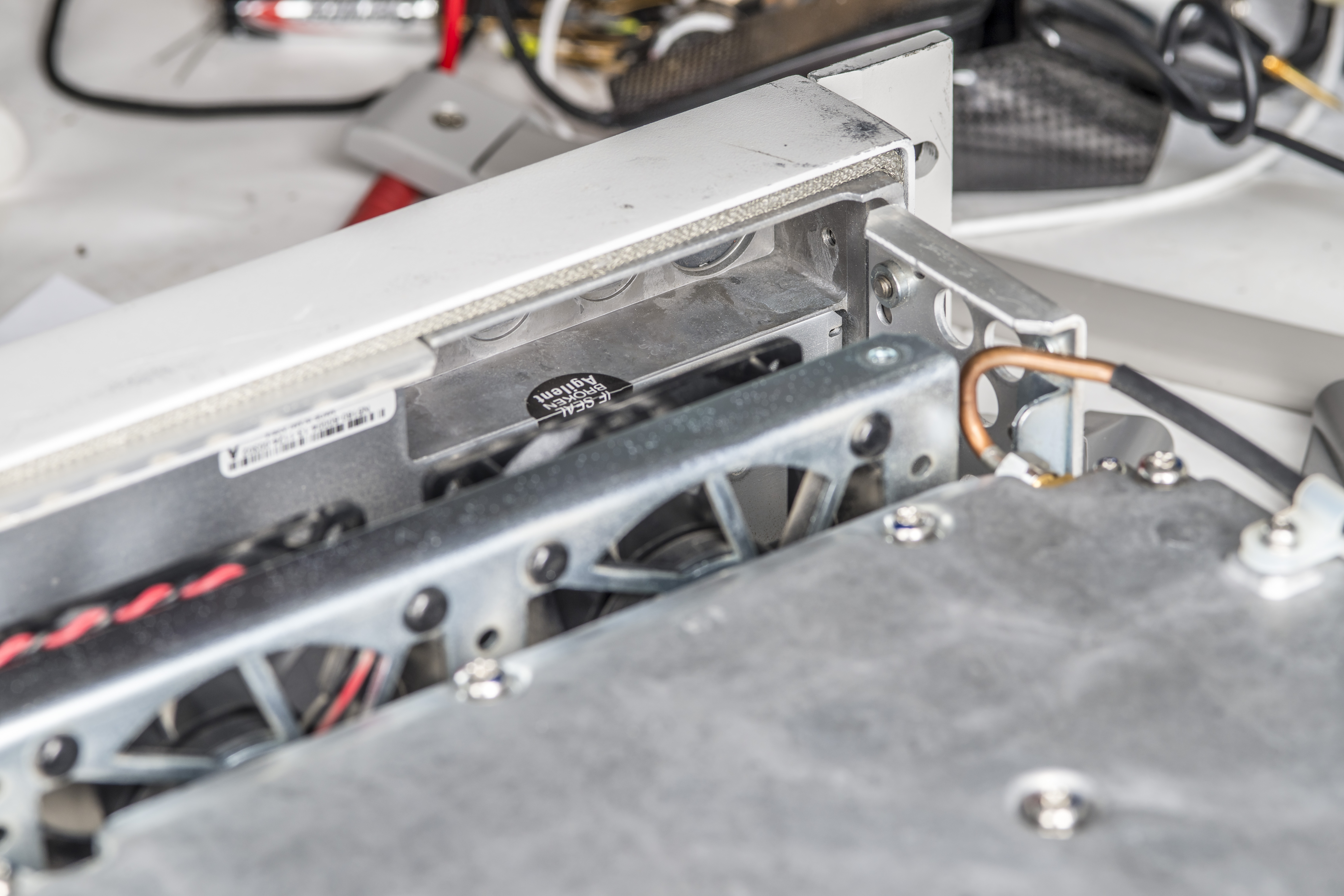
Instrument has no less then four 60mm fans. They are quite necessary since N5161A consumers about 120 W when running, which is quite a bit for such a compact instrument. Higher frequency units draw even more power for additional hardware.
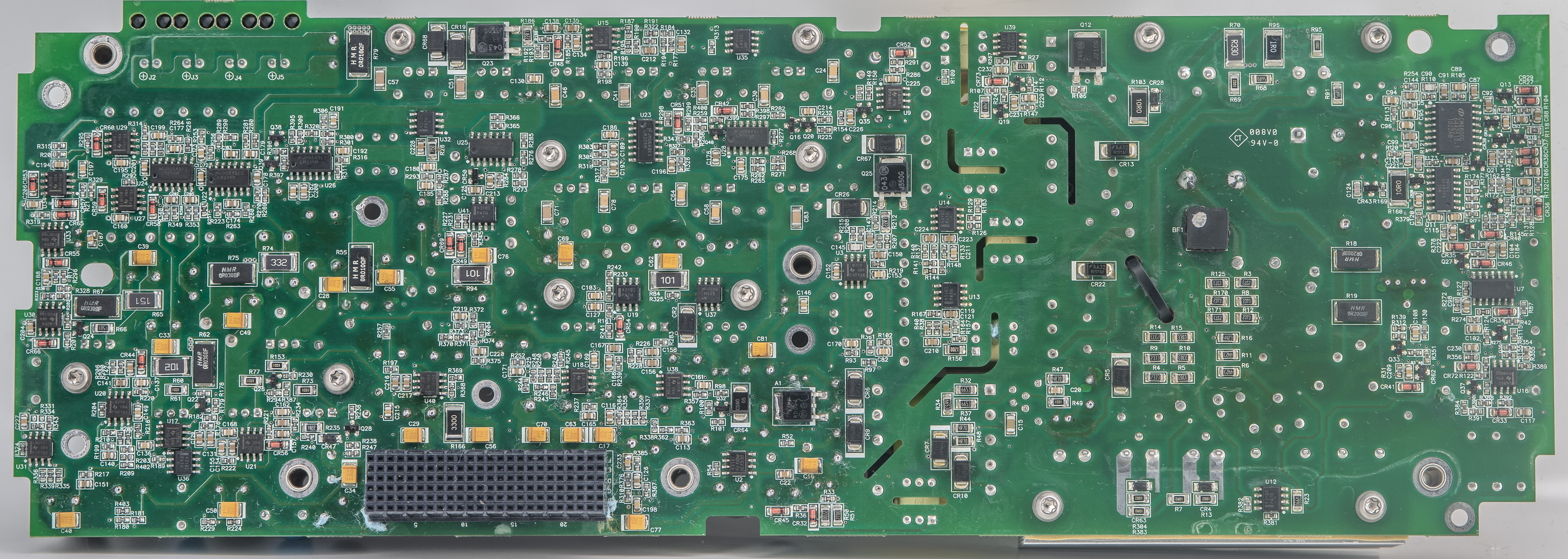
Bottom side has a large 8-layer mainboard PCB embedded inside two heavy aluminum cast shields of custom shape. CPU processor board is installed as a module at the back. It’s same processor board commonly used by Agilent/Keysight in many instruments.
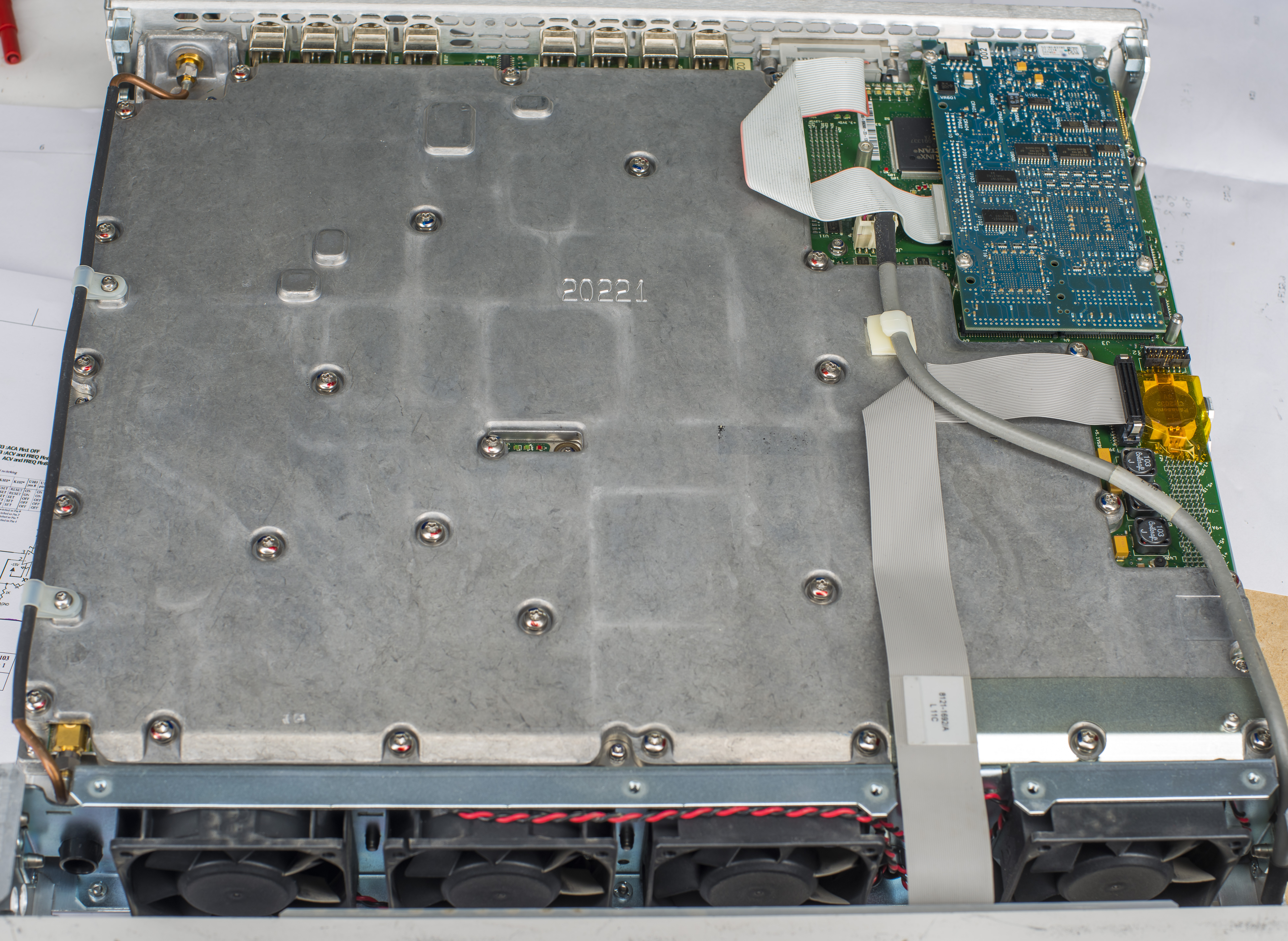
Output connector is connected to the front side of the mainboard with thick rigid SMA-SMA coaxial wire, neatly tied up to the shield mount locations. Cable rigidity helps with phase and dielectric parameters stability of the interconnect over time and during transport of the instrument.
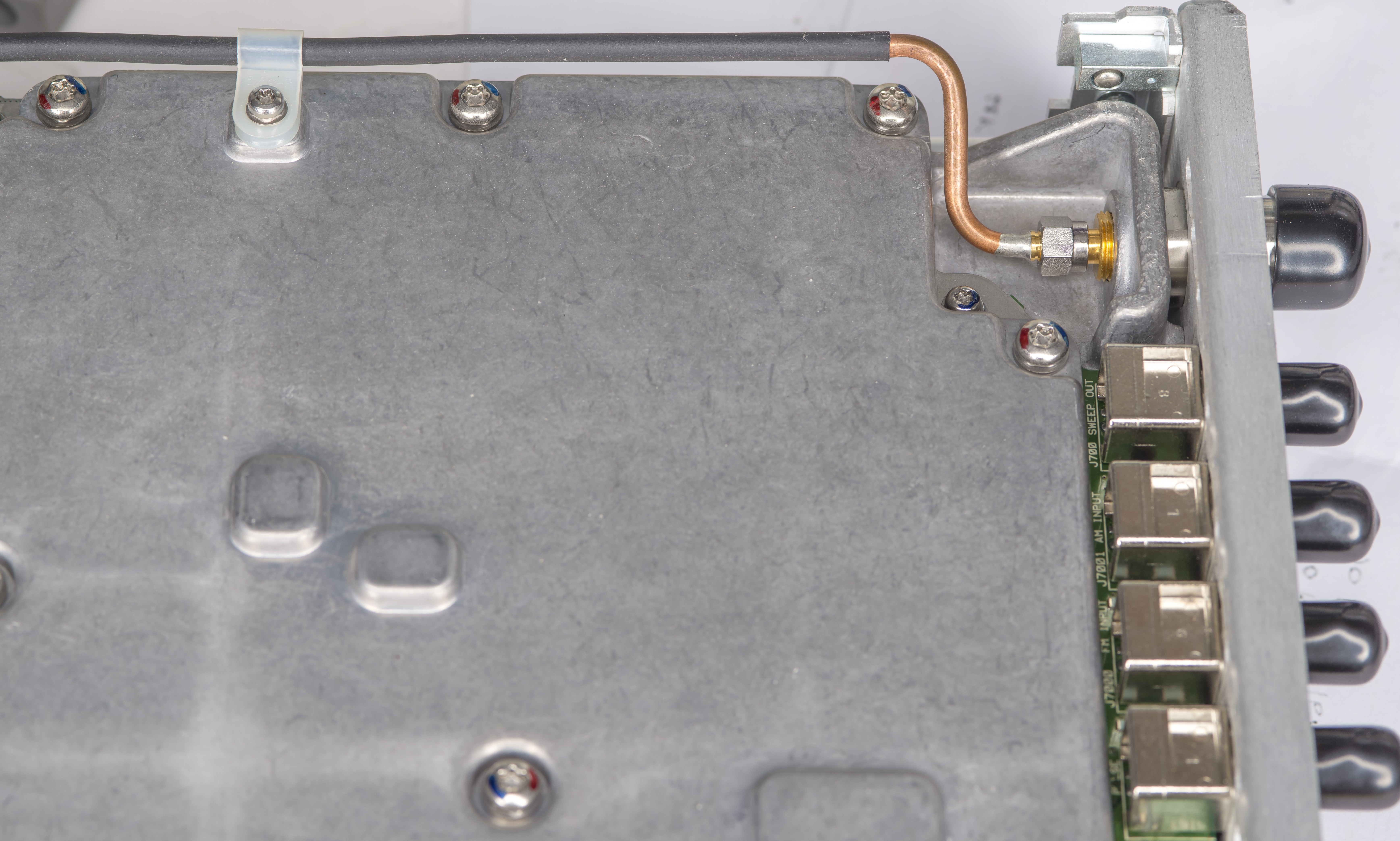
This was the first time in few years when I used SMA torque wrench to remove the rigid coax cable :).
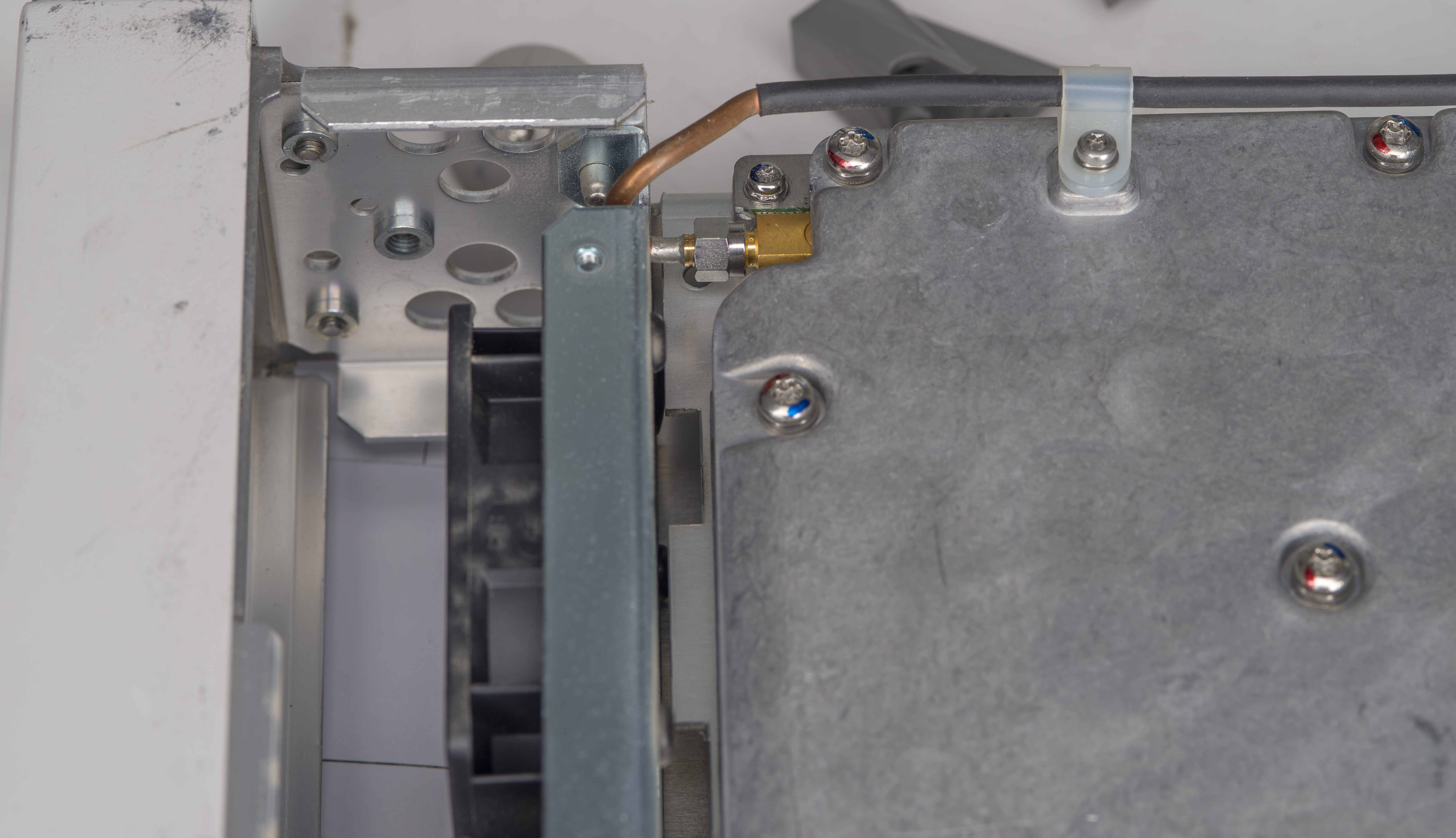
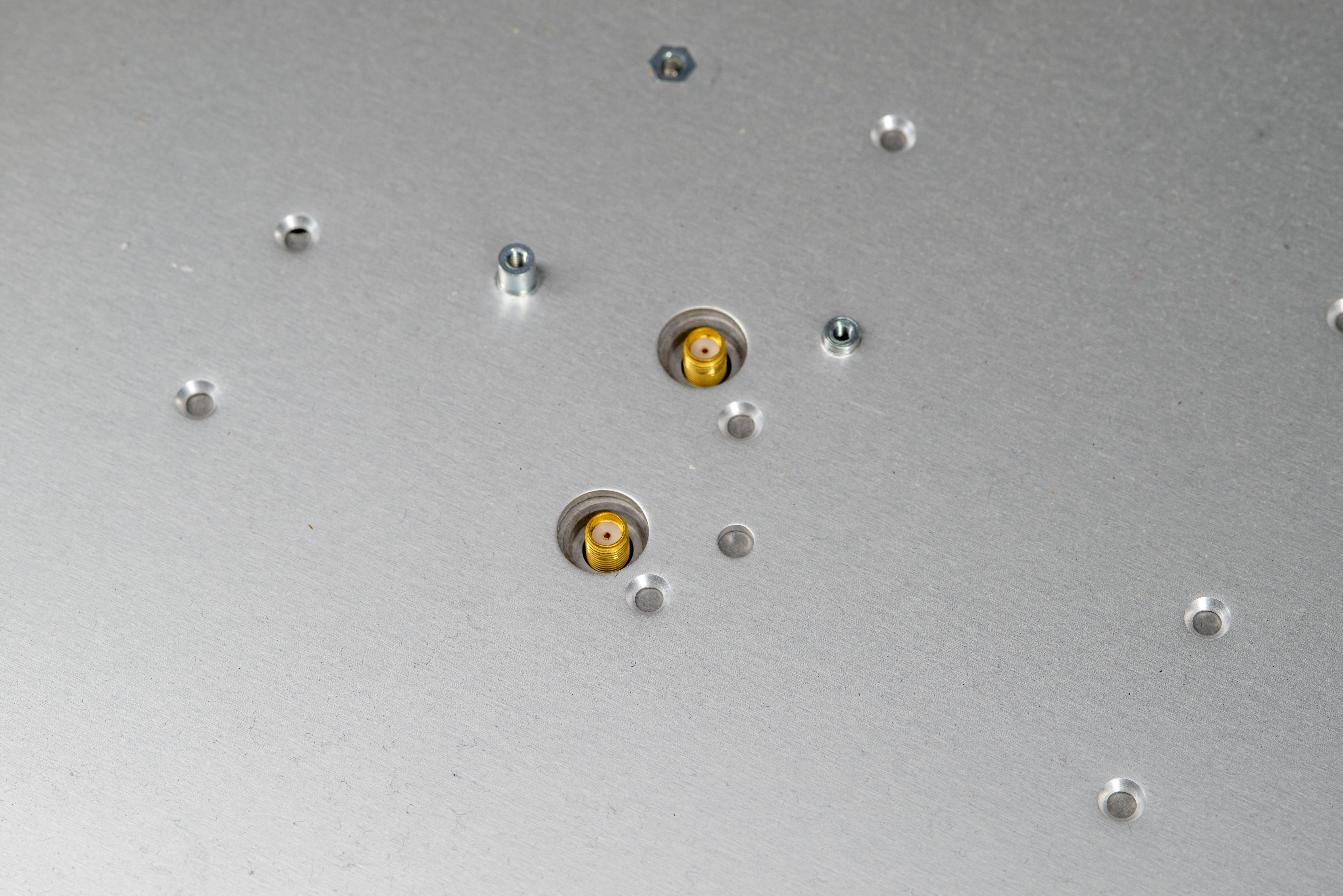
Mainboard have two SMA ports exposed to the top side, available for interconnecting with RF deck and additional hardware that higher end N5162A and N5182/5183A higher frequency RF generators. We don’t have any of that hardware in here, sadly, so there is no way to “upgrade” this instrument for frequency higher than 3 GHz.
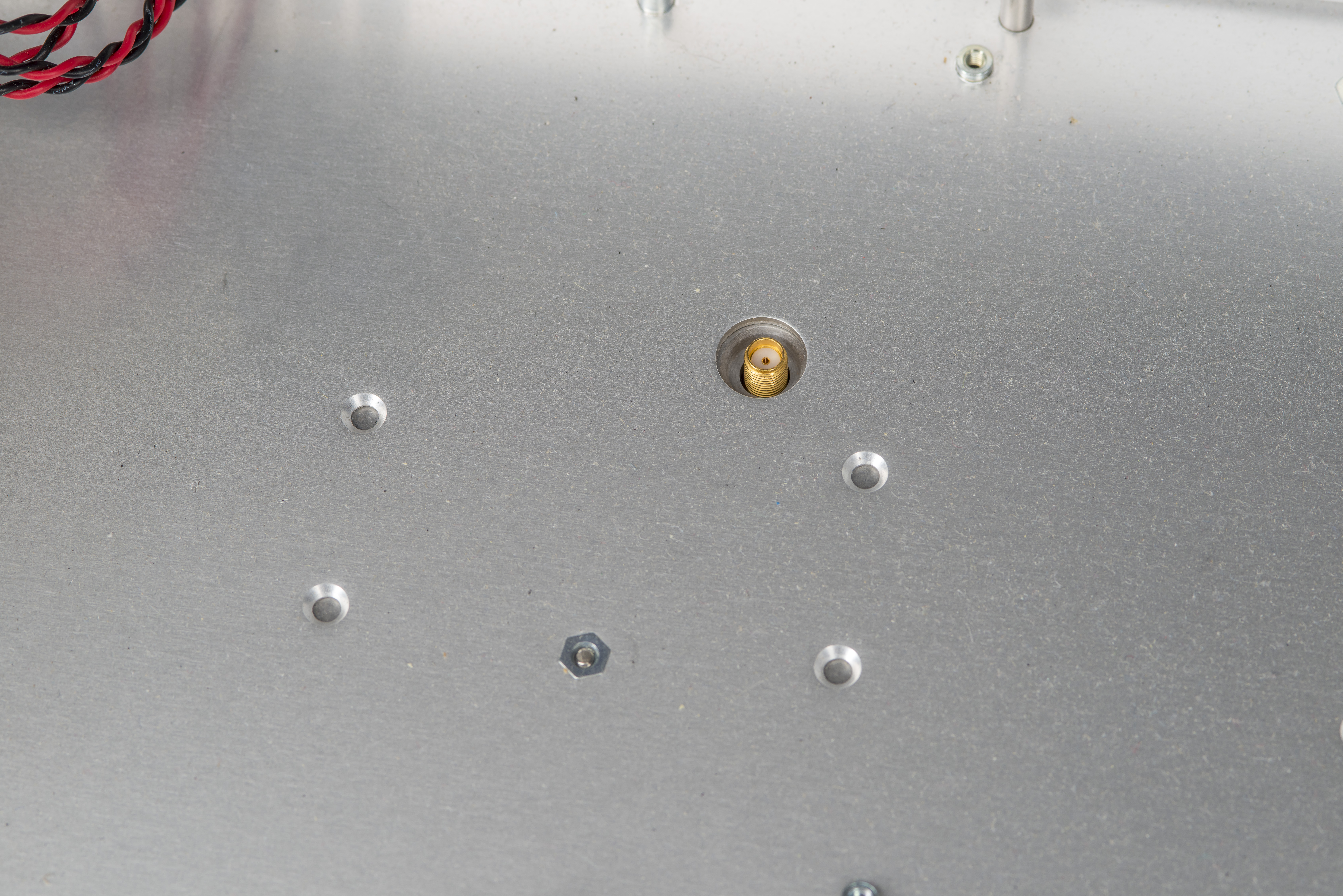
SMA interface port are routed thru the chassis openings available for additional hardware used in the higher frequency MXG generator models.
Each fan is connected with own cable to the power supply.
Front panel is actually fully metal casting with a metal mesh braid to have nice shielding and connection to the metal cover. RF instruments pay great attention to shield external interferences to sensitive internal hardware as well as prevent any emissions radiating outside of the instrument to the environment.
There are number of SMT LEDs all around the mainboard, some of them neatly presented in the special opening in the shield.
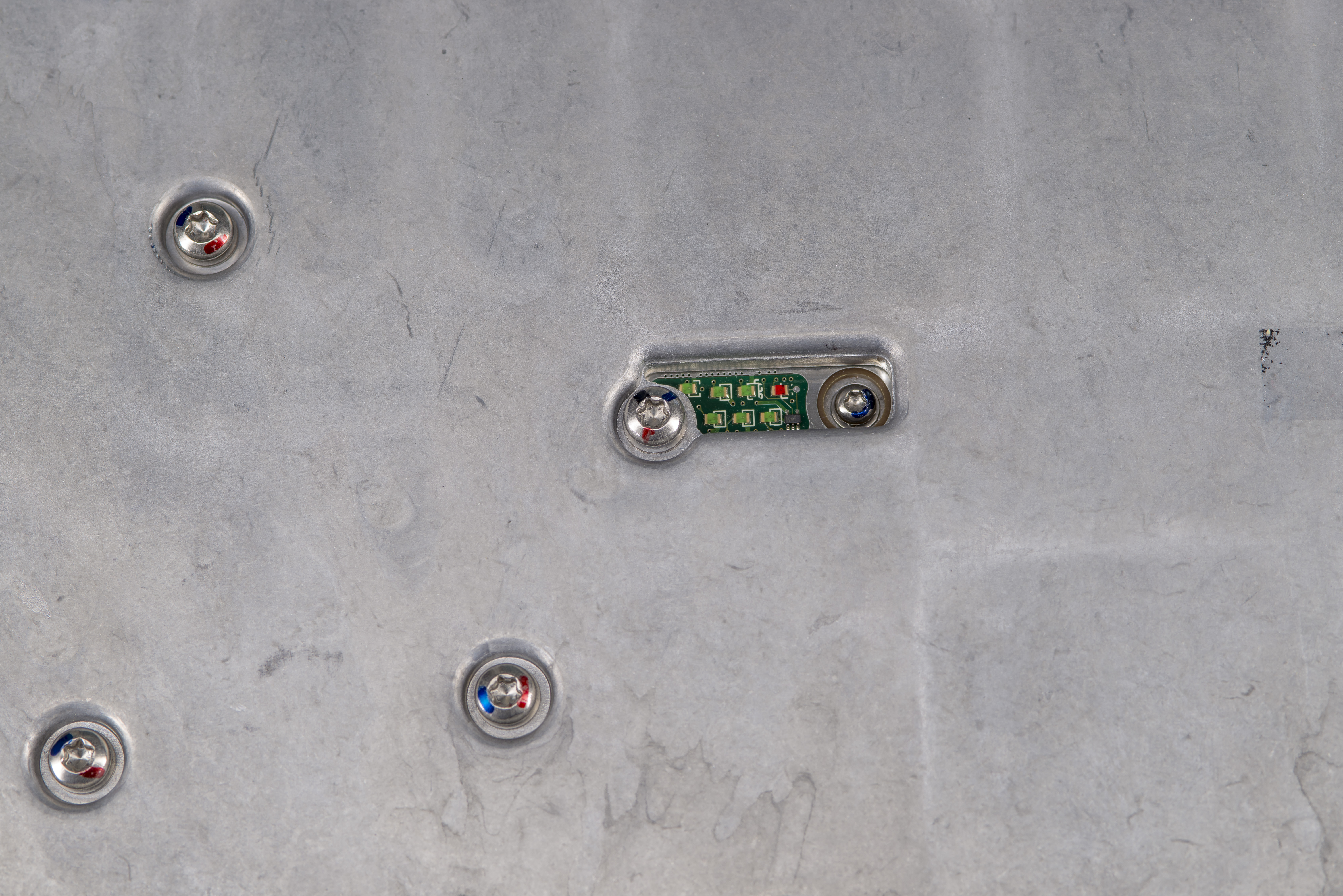
Shield has conductive gasket all around with some special RF absorbers in key important areas.

This heavy shielding is important and very common in RF equipment designs to reduce the coupling and interference between different circuits and blocks on the circuit board. At low frequencies ground planes and guard traces are effective way to shield the signals but as frequencies go higher cross coupling across the airgaps becomes a problem.
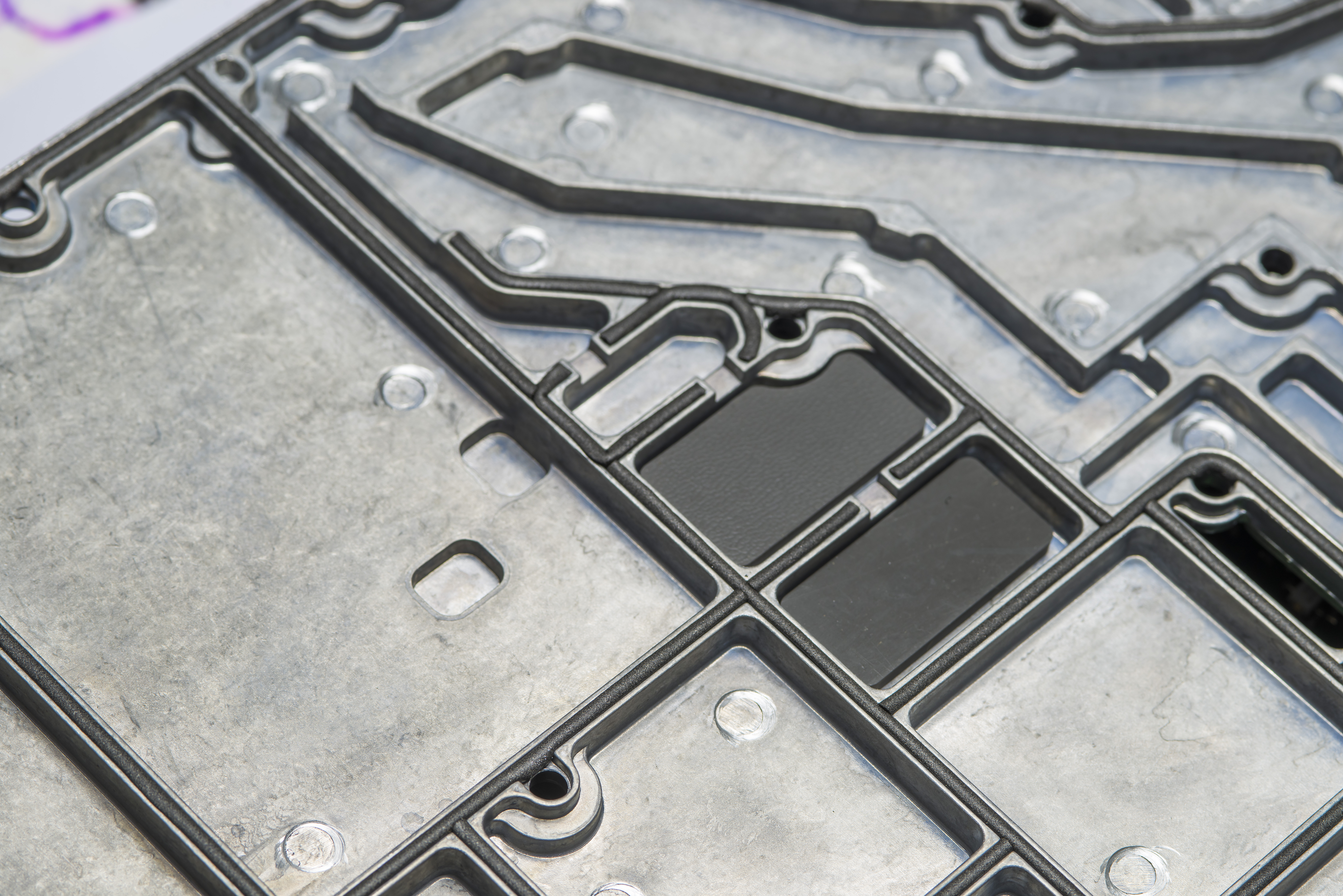
Shield also can be useful to maintain thermal regime of all the components on the PCB as it is in physical contact over the large area on PCB and can help to dissipate some of the power into the outer enclosure and chassis.

Coin cell is neatly taped out with kapton tape to avoid possible short-circuiting.

Let’s take a look at CPU board.
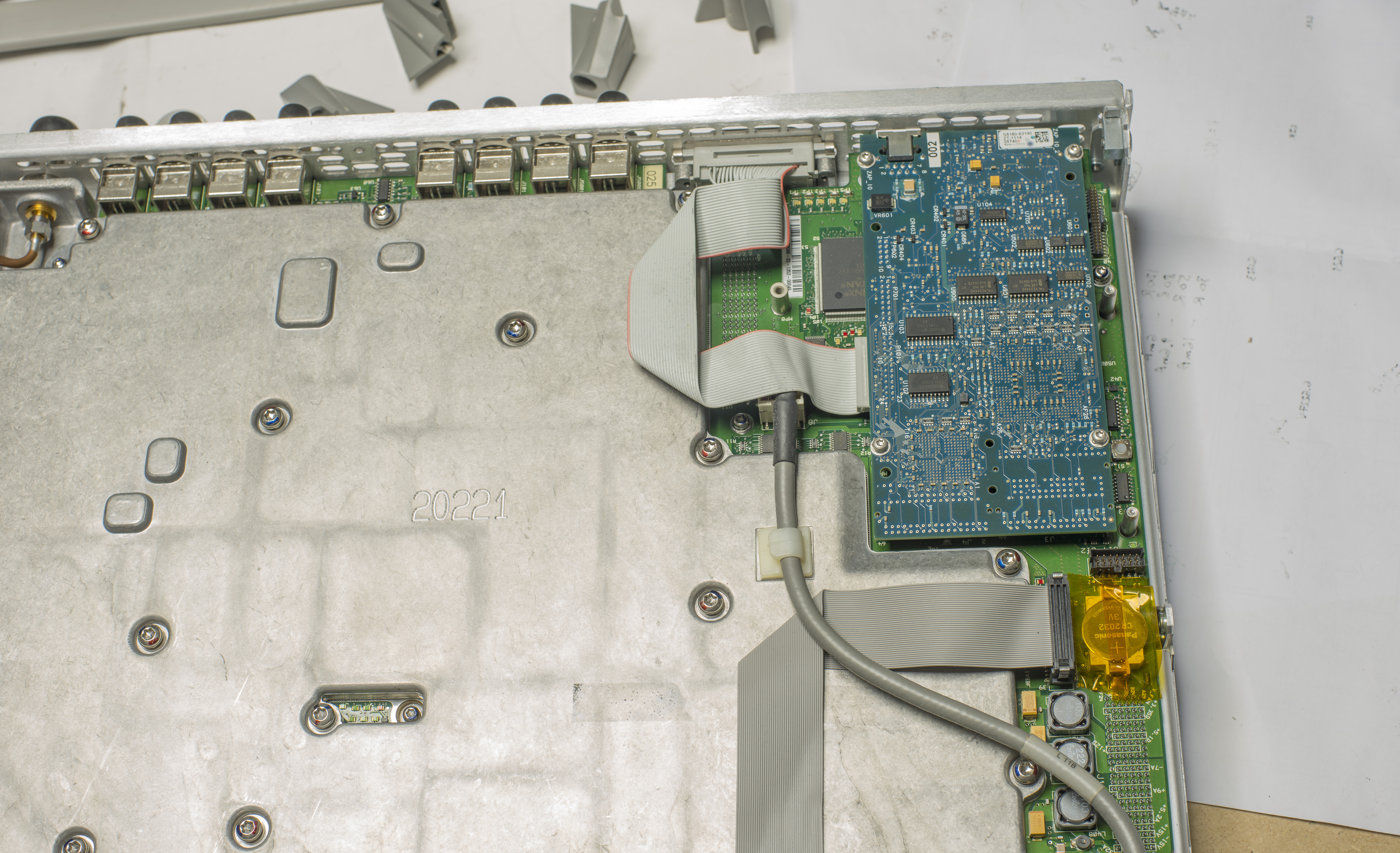
Small CPU module is implemented on separate blue PCBA. We have seen this module reused across many other Agilent instruments. It is efficient way to deal with portfolio of the instruments with different firmware but same hardware “brains” compared to separate digital processing hardware for each unique instrument.
Module has two exteranlly accessible ports – RJ45 network and unmarked mini-B USB receptacle. mini-USB port is provided only for manufacturing/service purposes and does not have documented purpose.

Component side has a copper film taped to the parts with adhesive to spread the heat a little bit. Based on the datecodes on parts this board was manufactured in 2010. I wonder if it’s same famous SPEAR series processor that is prone for FLASH memory failures that is quite common among many Agilent instruments manufactured earlier.

Now after removing a number of heavy-duty bolts we can finally remove the shield.

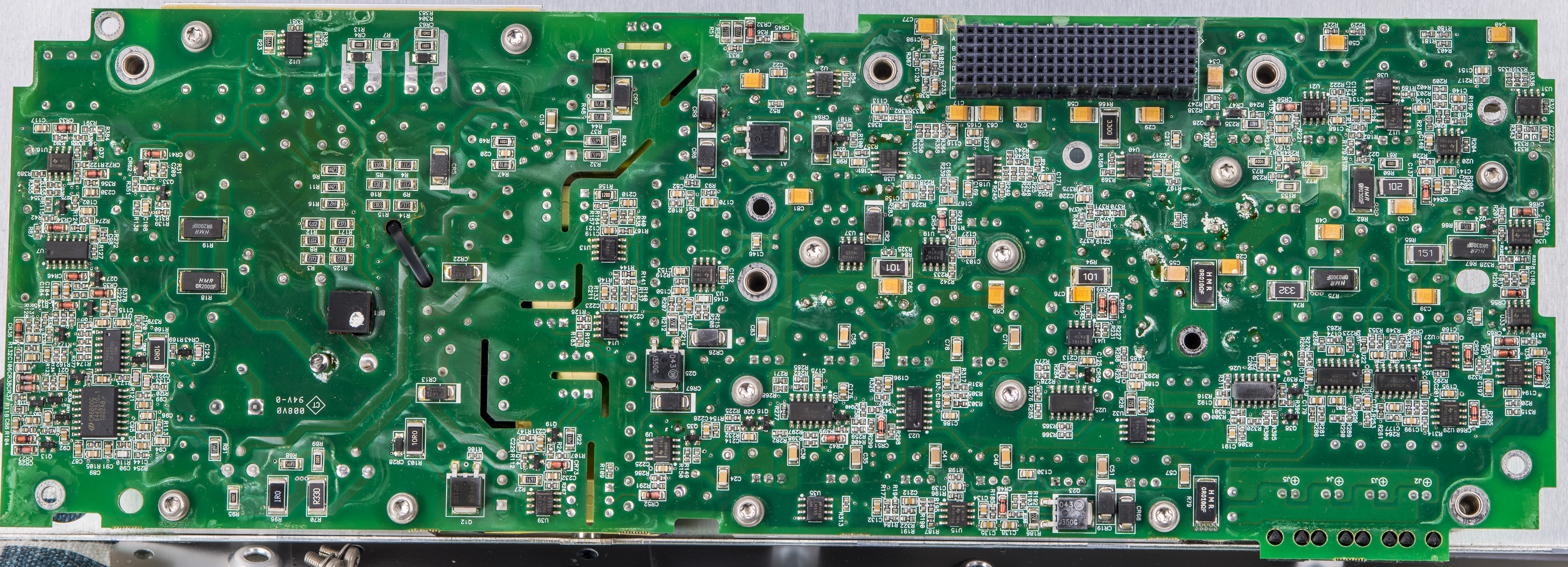
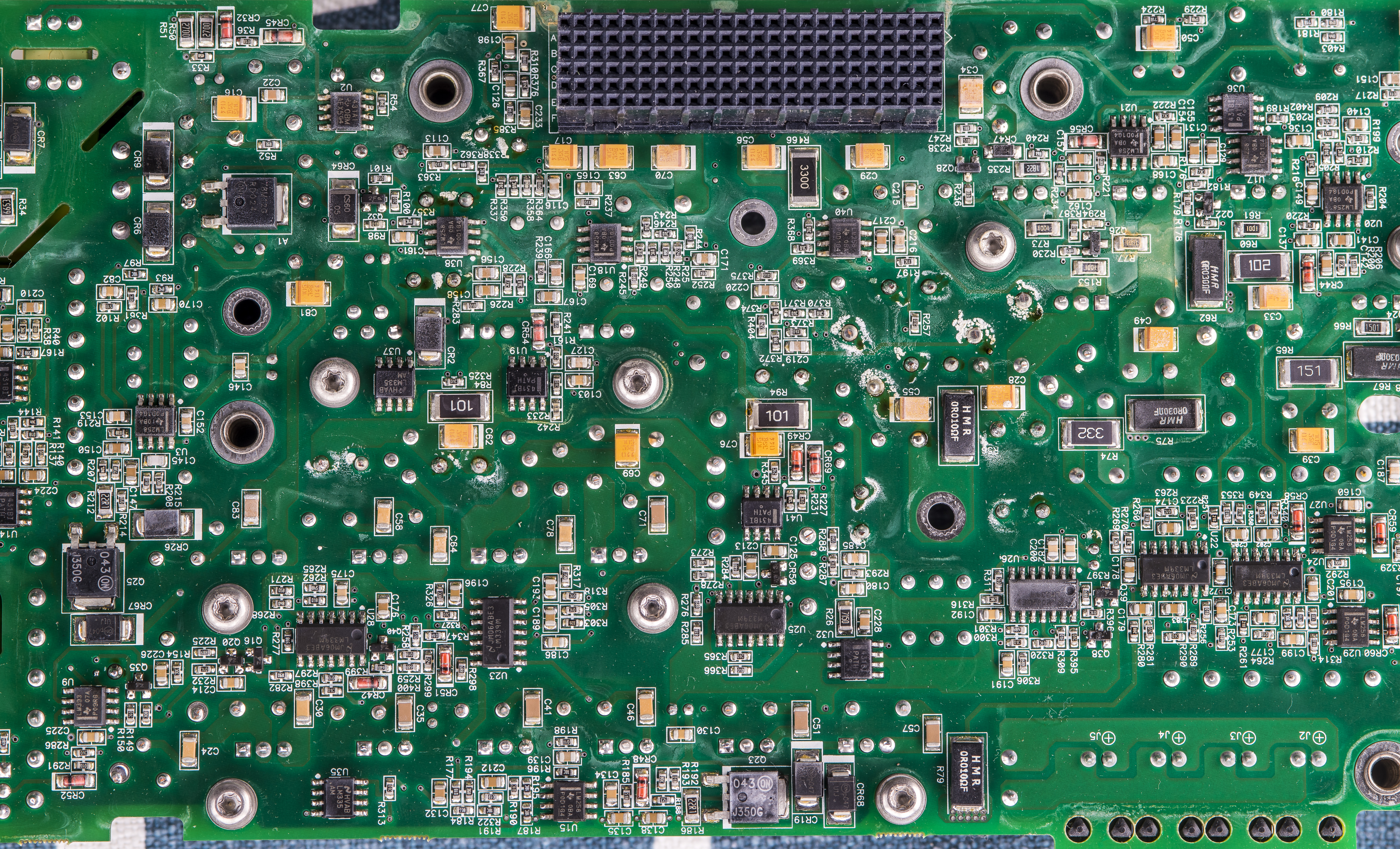
And overview of the mainboard in all it’s glory. Full resolution photo is available by clicking on the image, just like always at xDevs.com site.

I would not be pretending to understand what is going on with all the circuit blocks and sections on this complicated board, so let’s just enjoy and appreciate thousands of man-hours spent on each of the sections with help of high resolution photos.
We can see plenty of RLC filters and networks along various signal paths. Some local power supply regulators are sprinkled here and there with tantalum decoupling caps.
While components in funky packages are most likely mmWave RF parts like amplifiers, detectors or switchers. Most important blocks are even further separated with conductive pads or gaskets.
Interesting square packages close to the output SMA connector marked AT1, AT2 and AT3 are RF attenuators custom-made by Agilent with their internal part-number 1GM1-4234, 1GM1-4235 and 1GM1-4236. These even have red LED inside that lights up package during operation, which was shown by TheSignalPath during his TSP #163 episode about MXG N5182A repair . This video is also brilliant example of his troubleshooting and analysis on the MXG circuitry, highly recommended to watch.
There are plenty of Analog Devices ADG-multiplexers nearby as well, likely to control different attenuation levels of the output. Power is also carefully filtered thru large series inductors and capacitors around.

This whole section is filled with thousands of vias to enhance the shielding across the PCB layers and improve thermal performance as well.
Xilinx Spartan FPGA in the center of the board is used to control all the various sections and domains. T2000 is a transformer for signal conversion followed by number of LC circuits and some active part.

Repairing this circuit board could be a tricky business as none of the passive components have reference designator marking and there is no public schematic available from the Agilent/Keysight.
Yet another Xilinx Spartan SC3S1000 FPGA in BGA package hiding up on top, surrounded with Analog Devices DAC and ADC chips. This is most likely the block where all the waveform generation and digitizing is happening.
ONsemi QFN component with cryptic partnumber 1822-1124 is most likely some custom part designed per Agilent requirements and specs. Flux residue around two white packaged parts was not cleaned up after the assembly.

Main 10 MHz clock reference is VTXO610CTR manufactured by Rakon but it’s likely obsolete part already. I could find the only old datasheet. This Colpitts oscillator uses the direct two−port temperature compensation method. Operating on the fundamental mode, the circular AT−cut crystal is housed in the environmentally rugged UM−1 SLIM resistance weld package. It has ±1 ppm frequency stability over temperature and specified for ± 5 ppm/year drift over 10 years.


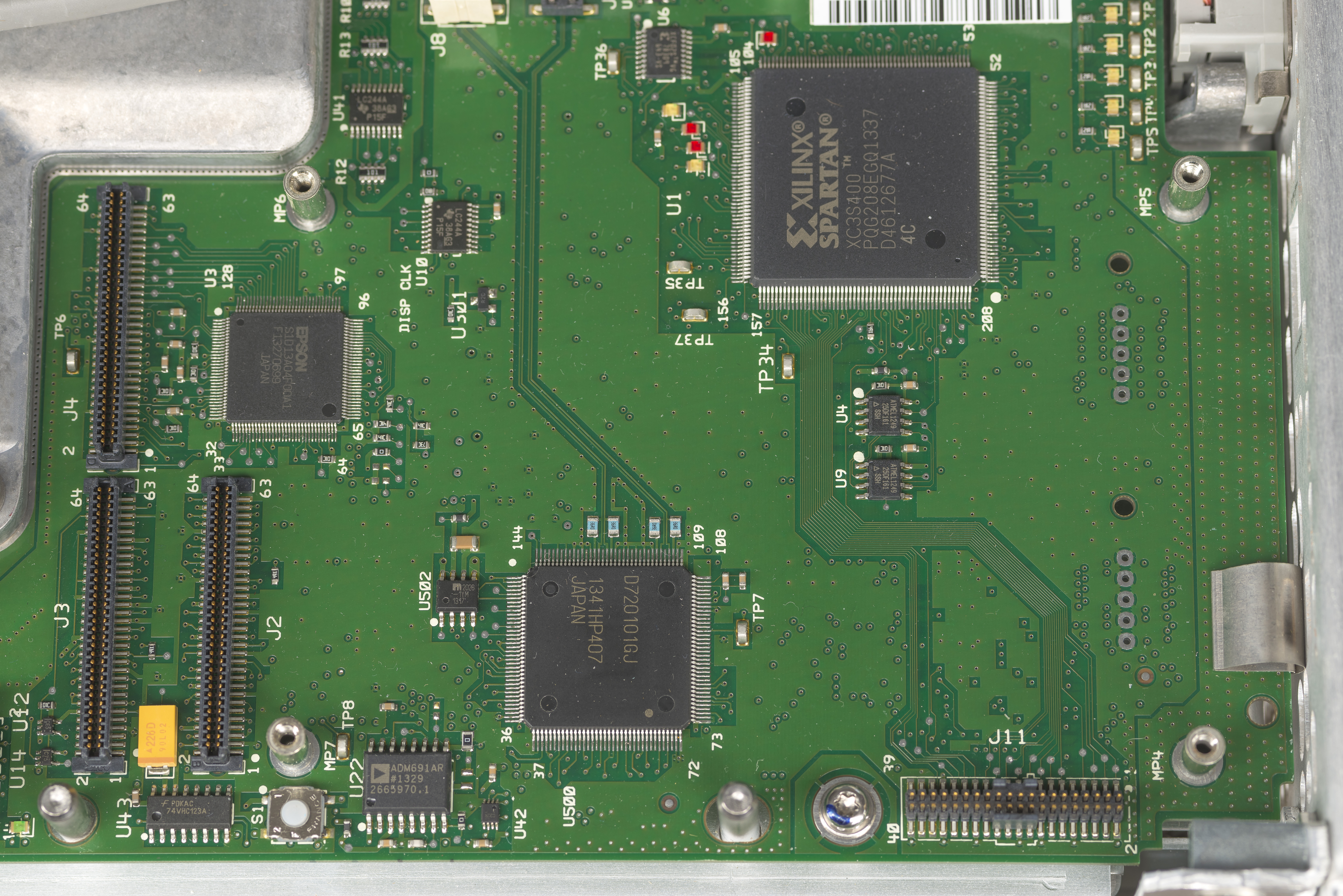
On the mainboard section outside of the RF shield we can also find few chips such as yet another Xilinx Spartan FPGA for glue logic, NEC 5-port USB 2.0 PCI controller uPD720101GJ and EPSON S1D13A04F00A1 LCD/USB companion chip which handles all display and 2D graphics functions for LCD and additional USB 1.1 port.
Mains AC/DC power supply assembly
Now that we have dead power supply suspect, let’s open up the main power supply and see what’s in there. It is built by NaoTech for Agilent with customized part-number 0950-4933.

This power supply is specifically designed to fit into MXG chassis with custom form-factor and press-fit interconnect on the bottom side. It’s rated for universal mains input with frequency up to 440 Hz (since some MXGs are designed for military use). PSU outputs no less than 11 DC output voltages:
- -7 Volt Analog rated for load up to 2.2 A
- -15 Volt Analog rated for load up to 1.3 A
- +32 Volt Analog rated for load up to 0.1 A
- +15 Volt Analog rated for load up to 2.9 A
- +5.2 Volt Analog rated for load up to 6.0 A
- +9(10.2) Volt Analog rated for load up to 4.3 A
- +12 Volt Digital rated for load up to 2.2 A
- +3.35 Volt Digital rated for load up to 6.5 A
- +5.1 Volt standby rated for load up to 0.3 A
- +5.1 Volt rated for load up to 1.9 A
- +9.2-14.2 Volt for fans rated for load up to 1 A
Stand-by vampire power when MXG is powered off but plugged in is about 2.5 W. Power switch button is a softkey and not a hard switch.
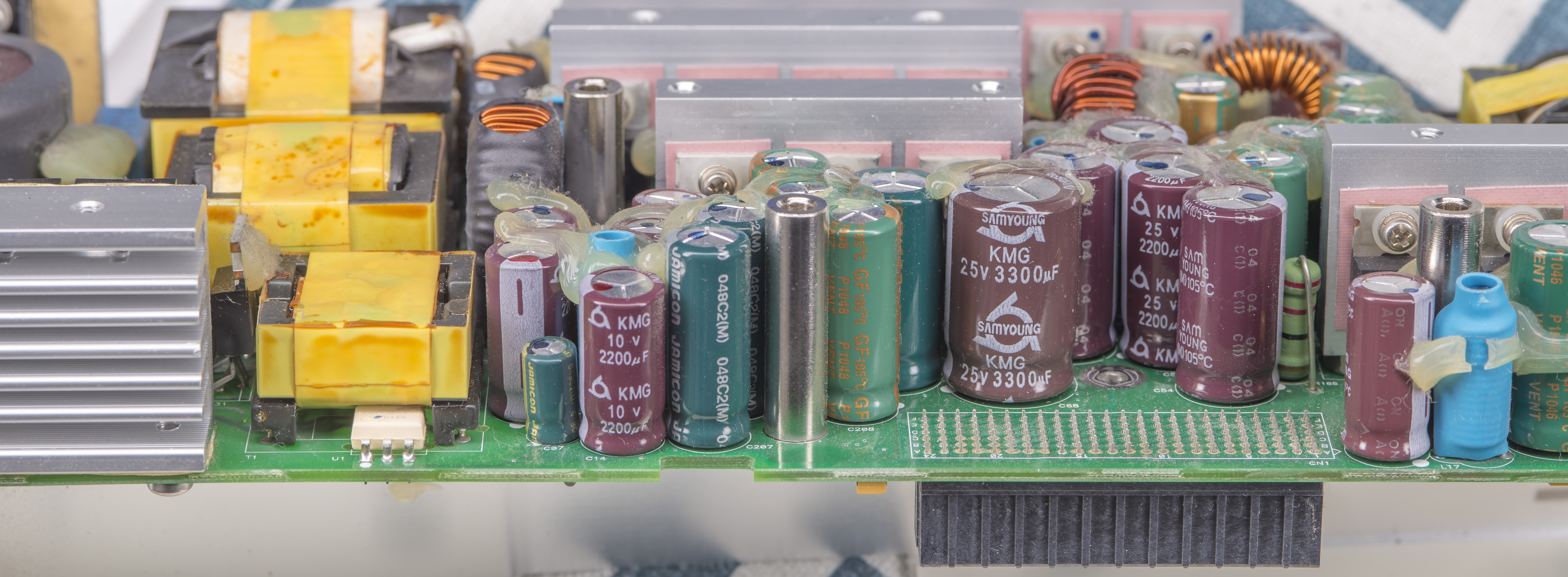
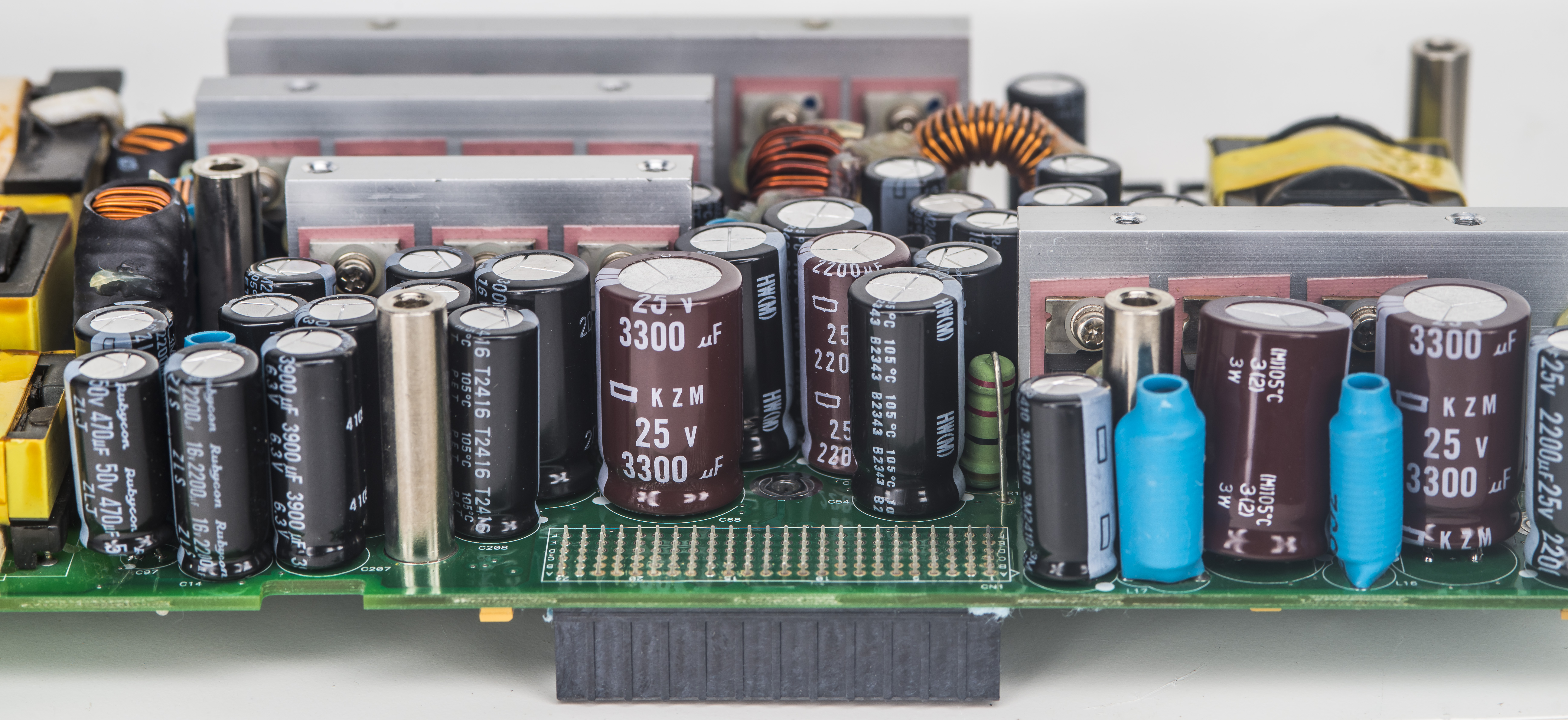
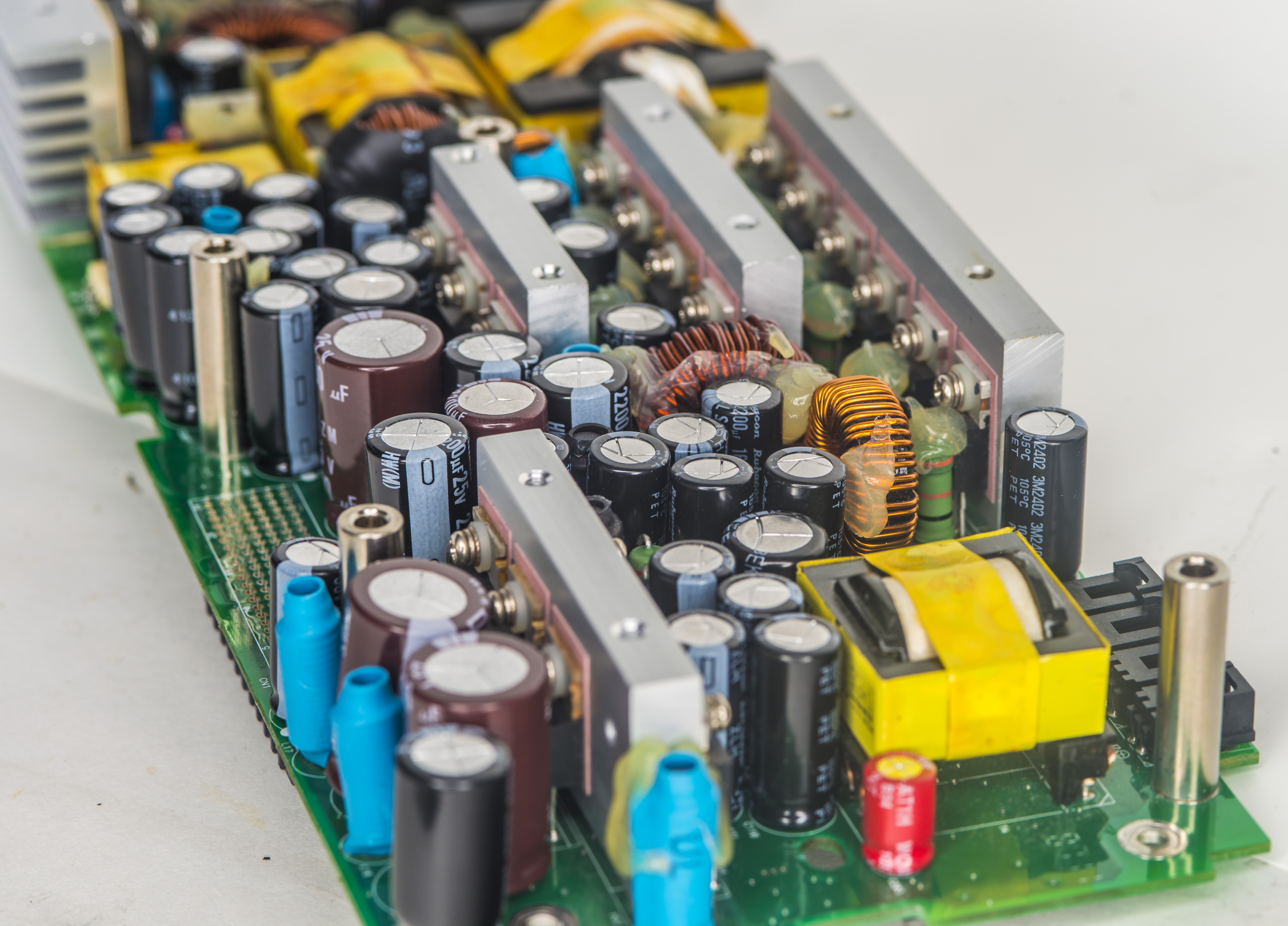
After removing million screws and taking board out we can see quite busy decent quality dual-layer PCB. There are number of SMT tantalums in parallel with electrolytics, number of regulators, opamps and comparators around and decent isolation with slots and cutouts.
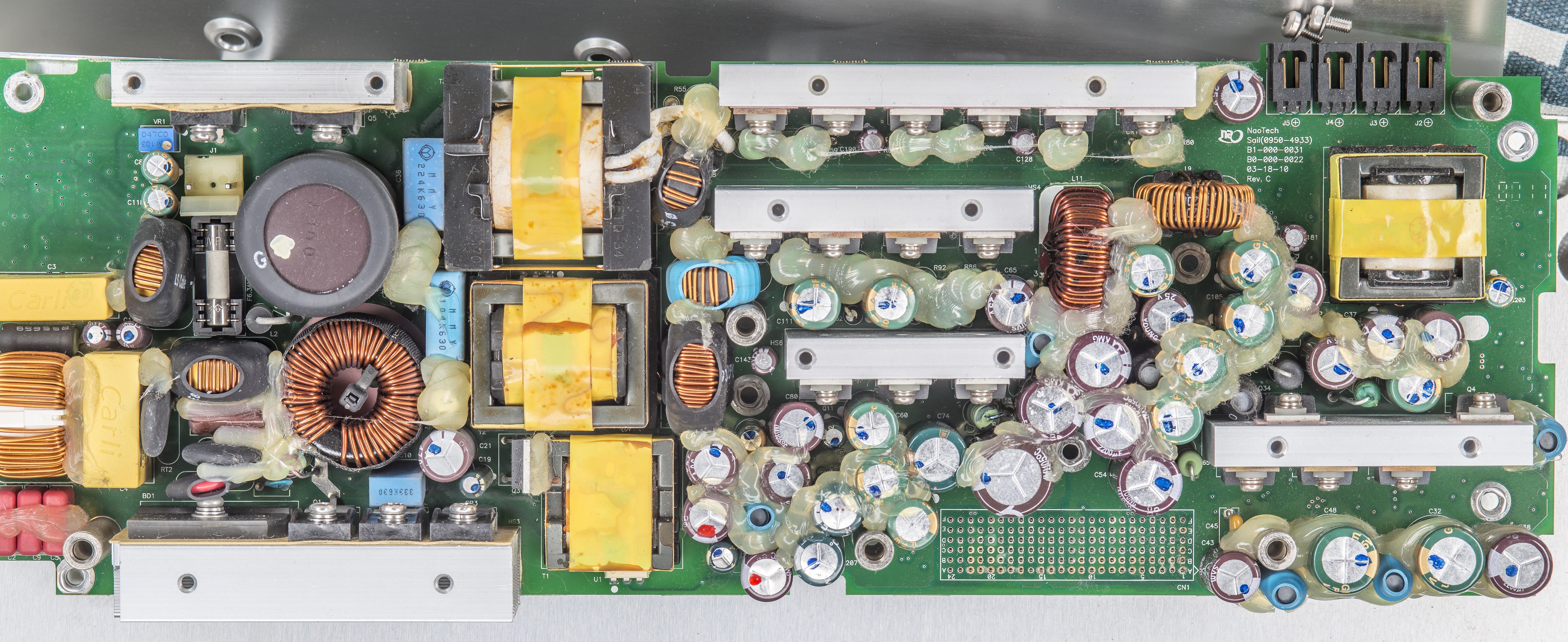
Like famous Marco Reps said once, Enemy spotted applied here. Just 1 second look is enough to clearly identify the problem with this dense power supply. It is filled with bad junk electrolytic capacitors. Some of them already have bulging vent slots, but I’m pretty sure they all are bad. In cases like this I don’t bother testing or measuring capacitors, just replace them outright.
It’s bit crazy to think that Agilent spent all the effort and hundreds k$ for all the wonderful RF design and R&D but yet skipped $20 on using good quality top brand electrolytic capacitors in the power supply.
I’ll leave the original tantalum capacitors in place but all noname electrolytics must go, no questions and no wasting time for their testing. They just don’t have place in such an expensive instrument or I would loose all the sleep at night.
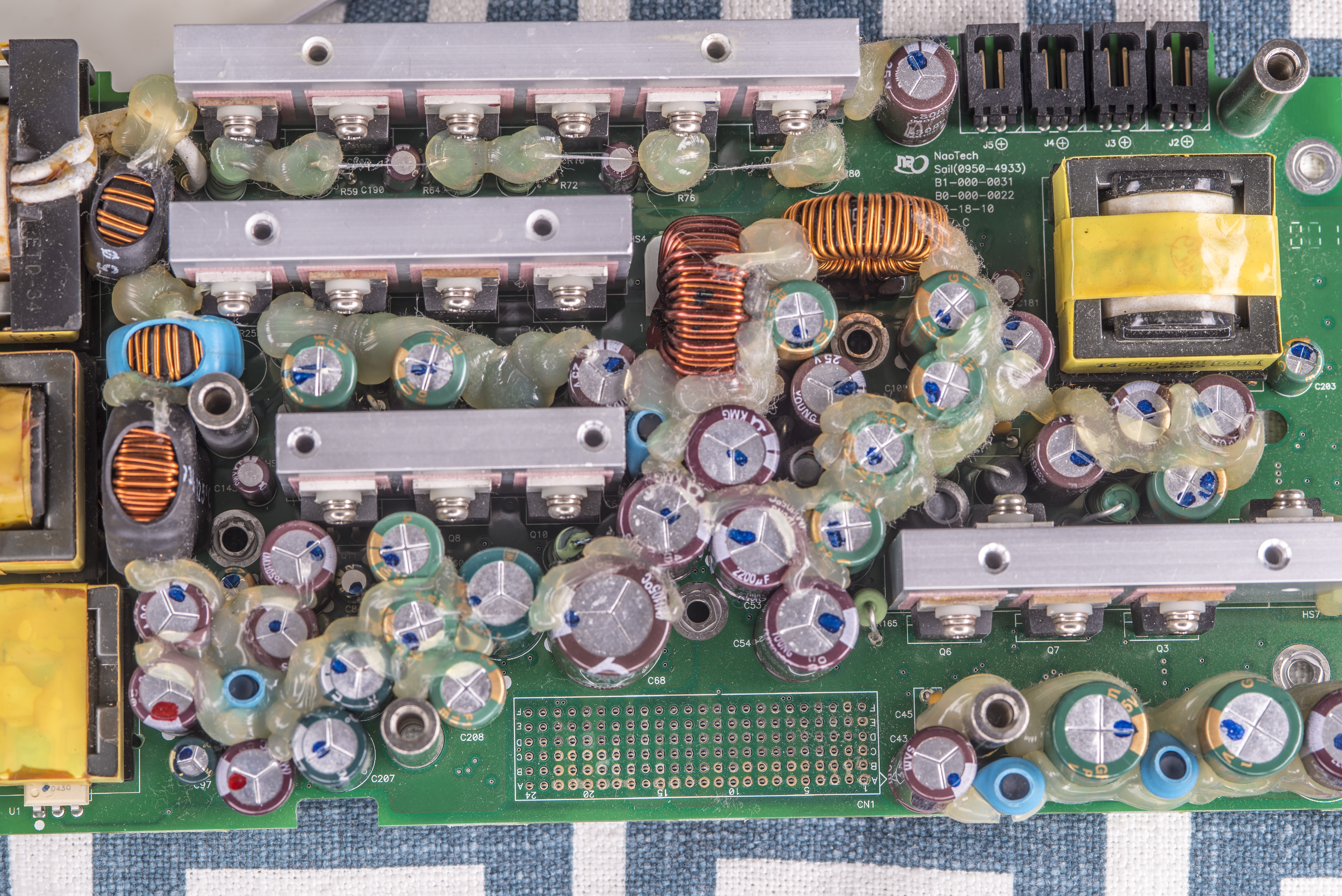
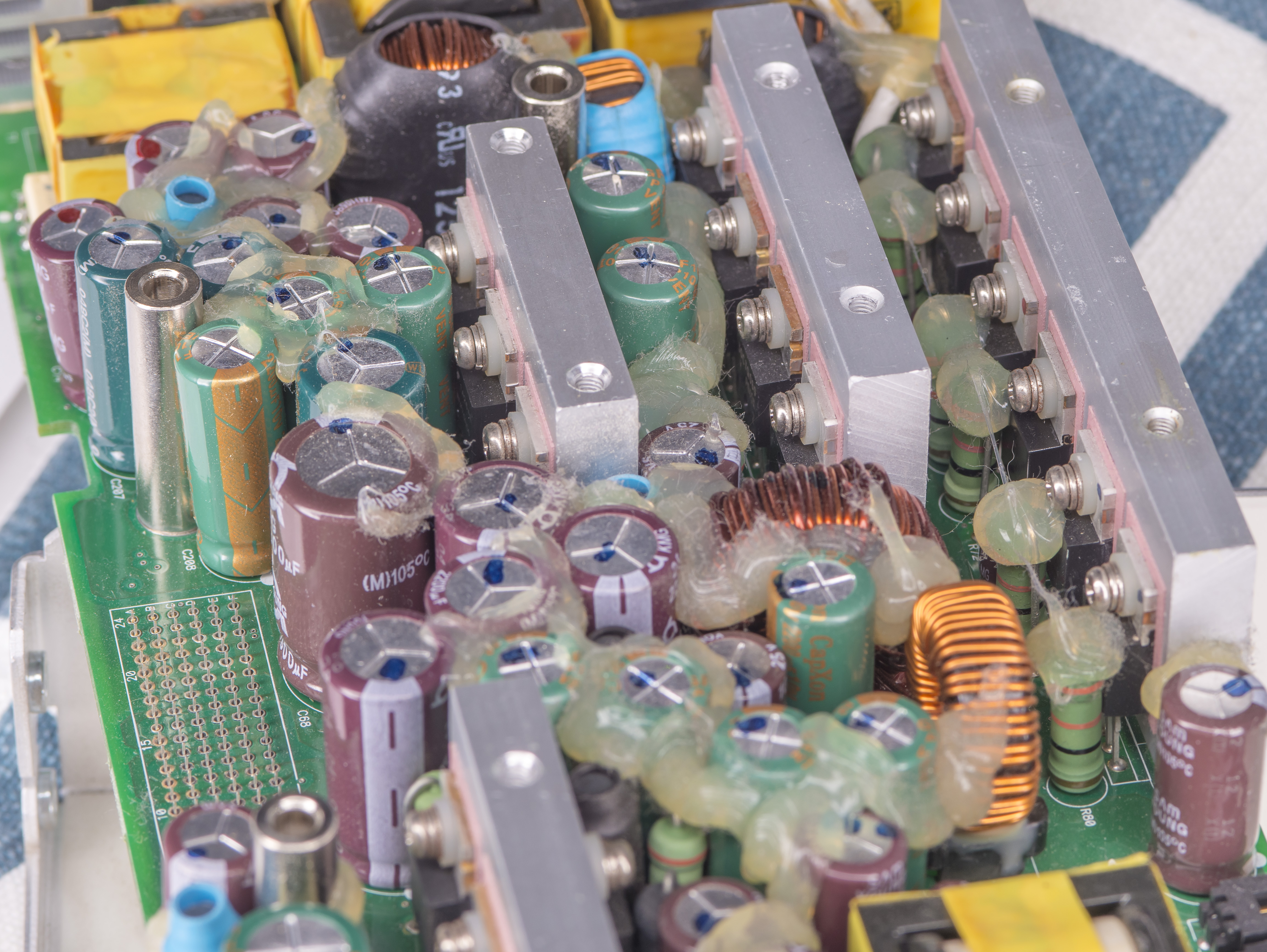
One last look at the galore of the junk caps:
Power supply manufacturer couldn’t even pick one specific crap brand and instead used a mix of various ones even for same nominal value. Gotta save that last 0.001$ to keep the management happy with maximixed profits! Who cares if the supply dies after 5 years in operation, right?
Lucky for me most of the capacitors are not connected to heavy dense copper planes and very easy to remove with a help of ERSA I-CON 80W iron. Whole extraction took about hour with a tea break.
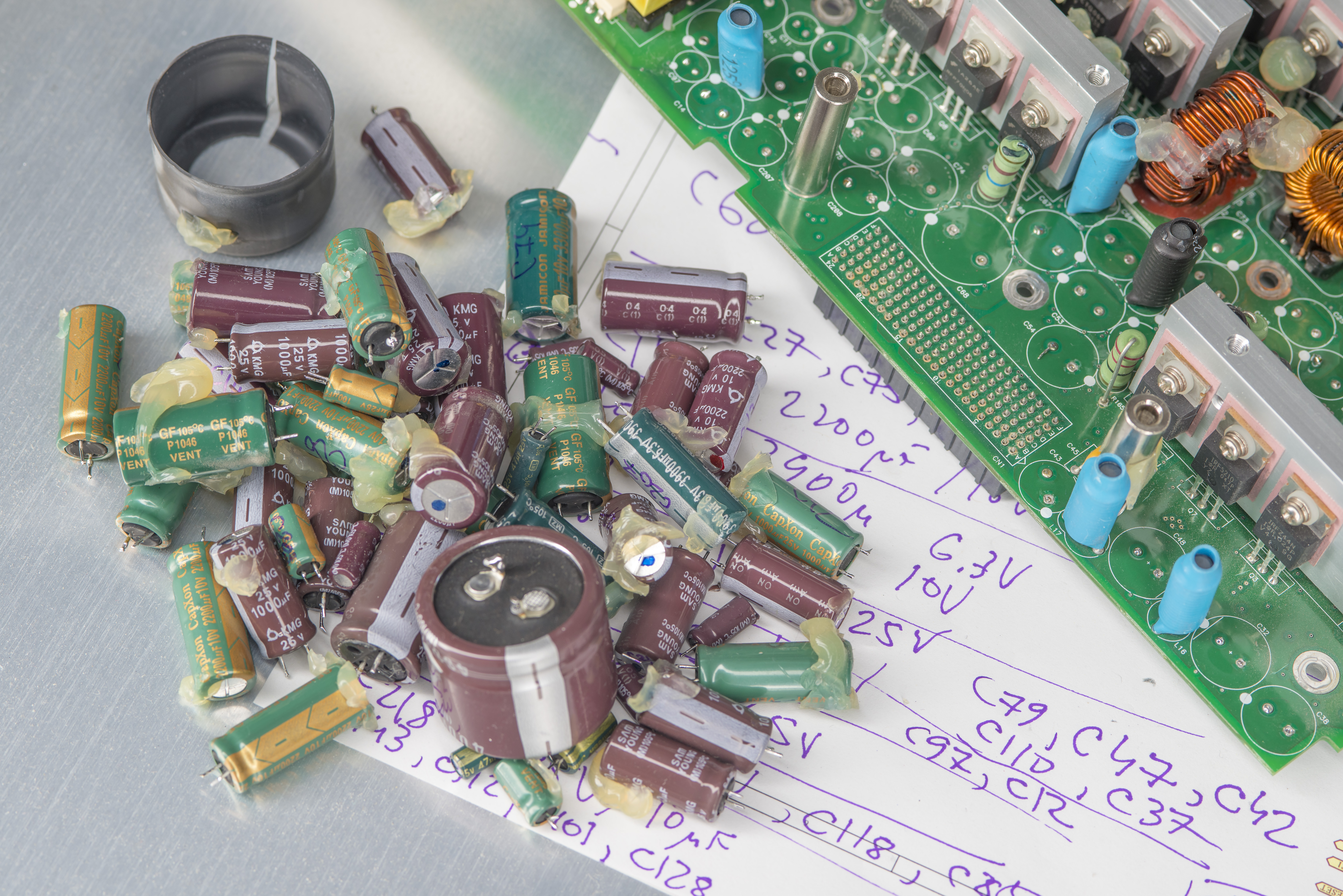
I have made a list of capacitors and their positions for other unlucky owners of MXG with dead supply:
| Capacitor value | Dimensions, DxH | Qty | Position |
|---|---|---|---|
| 3900 µF, 6.3 V | 10 × 27 mm | 2 | C61,C207 |
| 3300 µF, 10 V | 12.5 × 27 mm | 1 | C74 |
| 3300 µF, 25 V | 16 × 26.5 mm | 1 | C68 |
| 2200 µF, 25 V | 12.5 × 27 mm | 7 | C32,C38,C48,C53,C54,C66,C67 |
| 2200 µF, 10 V | 10 × 27 mm | 12 | C13,C14,C25,C26,C27,C59,C60,C73,C75,C105,C111,C208 |
| 1000 µF, 25 V | 10 × 25 mm | 8 | C31,C37,C79,C47,C52,C65,C110,C148 |
| 470 µF, 50 V | 10 × 22 mm | 4 | C12,C21,C43,C80 |
| 330 µF, 63 V | 10 × 22 mm | 1 | C42 |
| 150 µF, 400 V | 30 × 25, snap-in | 1 | C6 |
| 100 µF, 25 V | 6.3 × 12.5 mm | 4 | C11,C85,C118,C203 |
| 47 µF, 50 V | 6.3 × 12.5 mm | 1 | C97 |
| 47 µF, 25 V | 5 × 12.5 mm | 2 | C19,C84 |
| 10 µF, 35 V | 5 × 12.5 mm | 7 | C101,C112,C128,C143,C181,C190,C218 |
Repair and BOM list
First step in cases like this is to liberate the power supply from unworthy caps and then we can see if any other problems persist.
For capacitors replacement I like to use Rubycon and Nichicon capacitors rated for 10000 hours life at +105°C or similar. For switch-mode supply other parameters can be also important. Replacing capacitors is pretty boring process, so here are just the photos after everything was replaced and before installation back into the enclosure and chassis.
BOM parts of capacitors used for this repair. All of them are from top respected brands with long-life rating at +105 °C or higher. I also like to buy few more caps than needed so they can be reused for future projects and repairs elsewhere.
| DigiKey Part # | Manufacturer Part Number | Description | Quantity | Unit Price | Extended Price |
|---|---|---|---|---|---|
| P122290CT-ND | EEU-FS0J392LB | CAP ALUM 3900UF 20% 6.3V RADIAL | 2 | $1.03 | $2.06 |
| P122318CT-ND | EEU-FS1C332B | CAP ALUM 3300UF 20% 16V RADIAL | 1 | $1.00 | $1.00 |
| 565-EKZM250ELL332ML25S-ND | EKZM250ELL332ML25S | CAP ALUM 3300uF 25V POLAR | 1 | $1.37 | $1.37 |
| 493-6873-ND | UHW1E222MHD | CAP ALUM 2200UF 20% 25V RADIAL | 10 | $0.685 | $6.85 |
| 1189-2577-ND | 16ZLS2200MEFC10×25 | CAP ALUM 2200UF 20% 16V RADIAL | 12 | $0.687 | $8.24 |
| 1189-2960-ND | 25ZLH1000MEFC10×23 | CAP ALUM 1000UF 20% 25V RADIAL | 10 | $0.51 | $5.10 |
| 1189-50ZLJ470M10×20-ND | 50ZLJ470M10×20 | CAP ALUM 470UF 20% 50V RADIAL TH | 10 | $0.65 | $6.54 |
| P123403CT-ND | EEU-FS1J331LB | CAP ALUM 330UF 20% 63V RADIAL TH | 1 | $1.07 | $1.07 |
| 1189-2014-ND | 450VXG150MEFCSN30×25 | CAP ALUM 150UF 20% 450V SNAP TH | 1 | $5.60 | $5.60 |
| P14413-ND | EEU-FR1E101 | CAP ALUM 100UF 20% 25V RADIAL TH | 10 | $0.226 | $2.26 |
| 1189-50YXM47MEFR6.3×11-ND | 50YXM47MEFR6.3×11 | CAP ALUM 47UF 20% 50V RADIAL TH | 1 | $0.30 | $0.30 |
| 1189-4182-1-ND | 35ZLJ47MT15×11 | CAP ALUM 47UF 20% 35V RADIAL TH | 50 | $0.12 | $5.96 |
| 399-ESL106M050AC3AA-ND | ESL106M050AC3AA | CAP ALUM 10UF 20% 50V RADIAL TH | 10 | $0.131 | $1.31 |
This parts list total ended up around $60 USD with shipping included, plus some spare caps for other uses.

This replacement took few hours but was technically quite easy and simple. Board is pretty heavy and long so it would be a good idea to support it and handle with care to avoid excessive flexing or bending. This may crack the MLCCs and cause various problems in the long run. I didn’t bother to add hot-glue snails around caps as this MXG is not going into harsh field use environment but will sit in airconditioned lab instead.
Also as a precaution it’s great idea to replace film safety capacitors (big yellow 1 µF 275Vac X2 type) as they often can fail, especially with higher mains voltages. The failure isn’t obvious when inspected visually from above. Cap might look fine but when removed in two repair MXGs they had a big brown blast hole in the side and on the underside of the capacitor. Even if capacitor is good, it’s recommended to replace even just as a precaution, since film capacitors often can collect the humidity and die, like famous RIFA exploders in older HP equipment. When it fails it will burn the PCB top side to some degree. You may have to remove it to see if it has failed anyway. Credits to Jeremy R. for this tip.
Board after soldering and prior to cleaning for reassembly:
After checking polarity and spec of the each cap and position PCB was installed back into the frame and tested for power up standalone. Power draw and levels were OK, so next step was to install back into the MXG and test if it’s working. And working it is indeed!
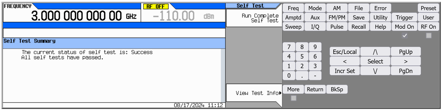
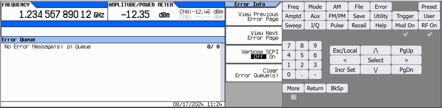
Happy unit reporting no errors, as expected from fully working instrument.
Checking voltages in “Attenuator voltages” self-test step also shows good values, well inside desired min/max range.
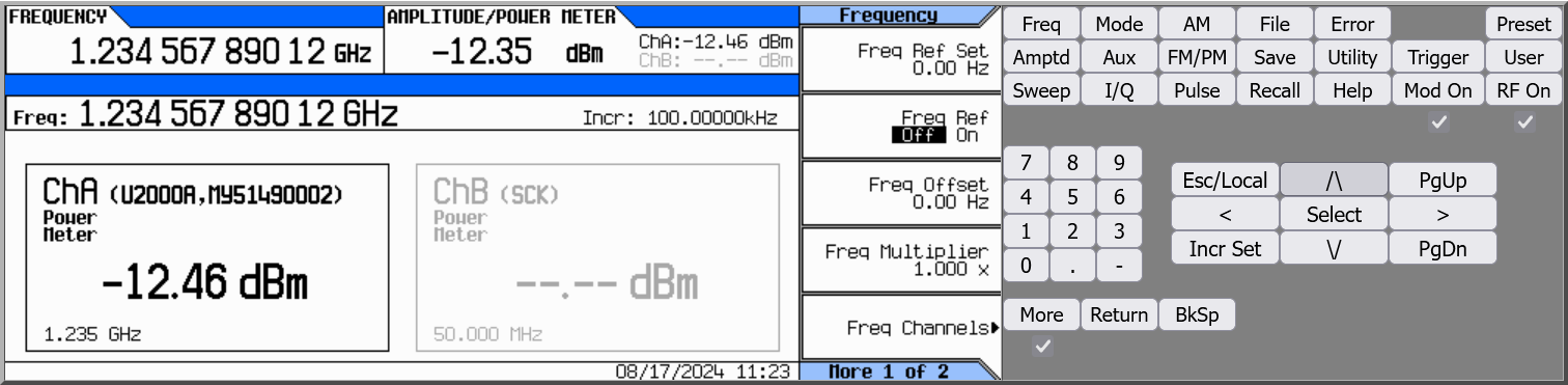
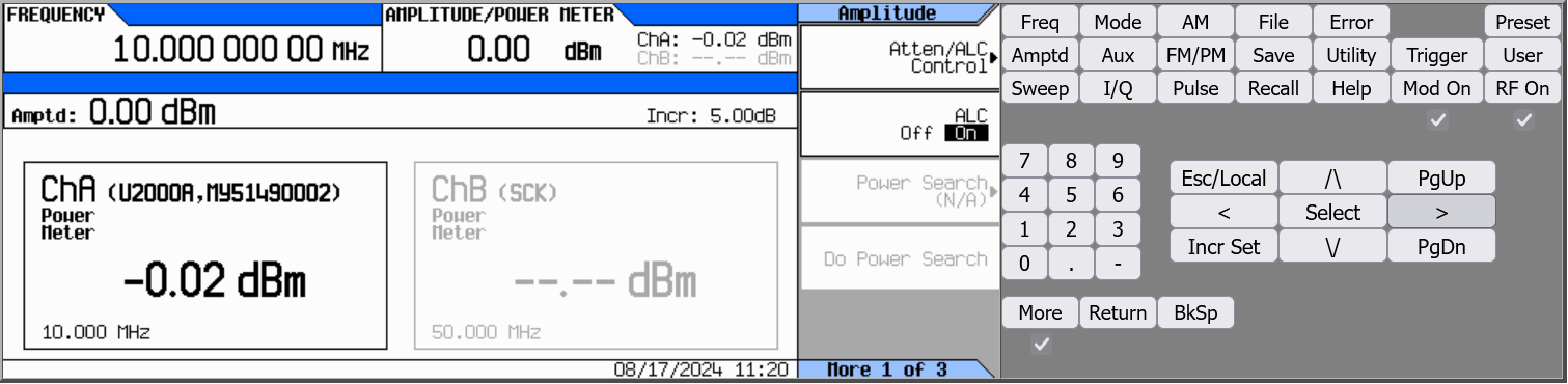
Spot checks at various frequencies and power output levels with Keysight U2000A USB power sensor also show no problems with output accuracy.
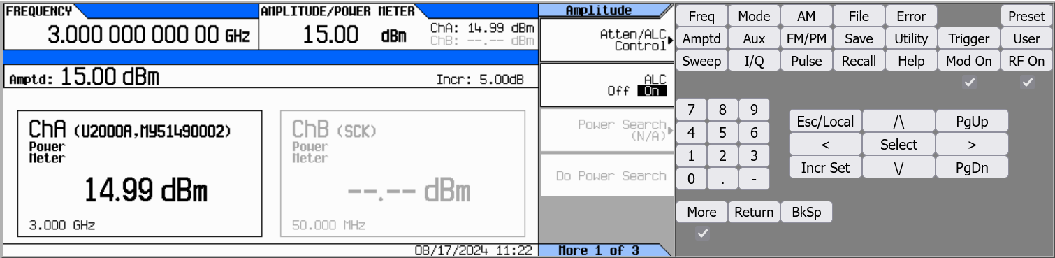
Summary and conclusion
With this we can add one more cool instrument to the lab capability and explore the RF signal generation in future. Now when you see MXG that does not power on you know what to do and prepare to replace 52 junk capacitors.
The author would like to express our appreciation to everyone contributed to this project, especially Tom. Discussion is very welcome thru comment section or at our own IRC chat server: irc.xdevs.com (standard port 6010, channel: #xDevs.com). If you have information and interesting ideas or experiments with MXG hardware not mentioned or listed in this article, feel free to provide them and xDevs will test and add them with next article update.
Projects like this are born from passion and a desire to share how things work. Education is the foundation of a healthy society - especially important in today's volatile world. xDevs began as a personal project notepad in Kherson, Ukraine back in 2008 and has grown with support of passionate readers just like you. There are no (and never will be) any ads, sponsors or shareholders behind xDevs.com, just a commitment to inspire and help learning. If you are in a position to help others like us, please consider supporting xDevs.com’s home-country Ukraine in its defense of freedom to speak, freedom to live in peace and freedom to choose their way. You can use official site to support Ukraine – United24 or Help99. Every cent counts.
Modified: Feb. 9, 2025, 6:52 a.m.