- Introduction
- Disclaimer
- Manuals references, firmware dumps and service information
- First tests and overall diagnostics
- Teardown time and internal construction of E8251A
- Repair and troubleshooting process
- A10 – E8251-60005 ALC board
- Testing A23 LowBand coupler/detector unit
- Day 2 – testing modules and blocks
- A8 E8251-60046 – Low Band Output PCBA
- A5 E8251-60043 – Sampler PCBA assembly
- A6 E8251-60044 – Frac-N PLL assembly
- A7 E8251-60073 – Reference PCBA assembly
- A9 – YIG driver board assembly
- A11 – Pulse/Analog Modulation Generator
- A18 – CPU board
- Summary and conclusion
Introduction
In this article we’ll take a look on broken E8251A 250 kHz to 20 GHz high-performance analog signal generator from Agilent. These units are still widely used in many labs and setups and can be very expensive. Unit I got today for repair is faulty and does not operate properly. These generators offer very good performance even today after decades of progress in test equipment development. PSG series are often valued high even in broken and damaged condition as many components in them are reused in newer stuff and still well serviced by the industry. It would be great to get this box back to 100% operational state to use in the lab.
Agilent/Keysight X-series of RF generators
Current benchtop analog signal generators offered from Keysight are summarized in table below. We looked at MXG RF model N5161A before, and now it’s time to investigate higher end obsolete today PSG-A model. Legacy PSG series include four models in the lineup:
- E8241A PSG-L, CW sine output only with frequency range from 250 kHz to 20 GHz
- E8244A PSG-L, CW sine output only with frequency range from 250 kHz to 40 GHz
- E8251A PSG-A, Analog output with frequency range from 250 kHz to 20 GHz
- E8254A PSG-A, Analog output with frequency range from 250 kHz to 40 GHz
Neither of these four models offer vector modulation functions like the modern PSG model options. Overall comparison table of some key features is presented below.
| Specifications | UXG | PSG MW | MXG MW | EXG MW | PSG-A | PSG RF | MXG RF | EXG RF | RF |
|---|---|---|---|---|---|---|---|---|---|
| Model number | N5193A | E8257D | N5183B | N5173B | E8251A | E8663D | N5181B | N5171B | N9310A |
| Frequency range (min. to max.) | 10 MHz to 40 GHz | 100 kHz to 70 GHz | 9 kHz to 40 GHz | 9 kHz to 40 GHz | 250 kHz to 20 GHz | 100 kHz to 9 GHz | 9 kHz to 6 GHz | 9 kHz to 6 GHz | 9 kHz to 3 GHz |
| Frequency switching speed | 180 ns | 9 ms | 600 μs | 600 μs | <15 ms | 9 ms | 800 μs | 800 μs | 10 ms |
| Sweep mode | Normal, list, fast CW, streaming | list, step, ramp | list, step | list, step | list, step | list, step, ramp | list, step | list, step | list, step |
| Minimum output power at 1 GHz | -80 dBm | -90 dBm | -90 dBm | -90 dBm | -135 dBm (1E1 opt) | -90 dBm | -127 dBm | -110 dBm | -127 dBm |
| Maximum output power at 1 GHz | +10 dBm | +24 dBm | +23 dBm | +23 dBm | +16 dBm (1EA opt) | +21 dBm | +24 dBm | +21 dBm | +13 dBm |
| Level accuracy at 1 GHz | ±1.5 dB | ± 0.6 dB | ± 0.6 dB | ± 0.6 dB | ± 0.6 dB | ± 0.6 dB | ± 0.6 dB | ± 0.6 dB | ± 1.0 dB |
| SSB phase noise at 1 GHz | -144 dBc/Hz (10 kHz offset) | -147 dBc/Hz (10 kHz offset) | -146 dBc/Hz (10 kHz offset) | -122 dBc/Hz (20 kHz offset) | -134 dBc/Hz (20 kHz offset) | -147 dBc/Hz (10 kHz offset) | -146 dBc/Hz (10 kHz offset) | -122 dBc/Hz (20 kHz offset) | -95 dBc/Hz (20 kHz offset) |
| Harmonics at 1 GHz | -40 dBc | -55 dBc | -33 dBc | -33 dBc | -55 dBc (>2 GHz) | -55 dBc | -35 dBc | -35 dBc | -30 dBc |
| Non-harmonics at 1 GHz | -70 dBc | -80 dBc | -92 dBc | -72 dBc | -82 dBc | -80 dBc | -92 dBc | -72 dBc | -50 dBc |
| AM rate | DC to 10 MHz | DC to 100 kHz | DC to 100 kHz | DC to 100 kHz | DC to 100 kHz | DC to 100 kHz | DC to 50 kHz | DC to 50 kHz | 20 Hz to 20 kHz |
| Maximum FM deviation | 600 MHz | 128 MHz | 128 MHz | 320 MHz | N*8 MHz | 16 MHz | 16 MHz | 40 MHz | 100 kHz |
| Maximum PM phase deviation (normal mode) | 12π | 1280 rad | 64 rad | 160 rad | N*80 rad | 160 rad | 8 rad | 20 rad | 10 rad |
| Narrow pulse width | 10 ns | 20 ns | 20 ns | 20 ns | 10 ns to 42s | 20 ns | 20 ns | 20 ns | 100 μs |
Newer UXG, MXG and EXG series generators also support interfacing Keysight USB power meters which can be very handy for calibration or complicated RF tests and experiments. These generators can be used to generate various protocol signals such as pulse-trains, AM, FM, PM, step/list sweeps. Vector versions of these generators can do most of modern communication protocols as well, such as 5G NR, LTE/LTE-Advanced FDD/TDD, W-CDMA/HSPA+, cdma2000®, GSM/EDGE/Evo, V2X,WLAN 802.11a/b/g/j/p/n/ac/ah/ax,Bluetooth®,IoT (Internet of Things),DFS Radar Profiles, Mobile WiMAX,FM Stereo/RDS, DAB/DAB+/DMB, Land Mobile Radio (LMR), Global Navigation Satellite Systems (GNSS).
Handy upgrade path chart presented below reveals coarse relationship from legacy HP/Agilent generators to current models:
Older PSG series do not have support for USB power sensors or pulse train generation capabilities, as they are running older computers with legacy codebase. PSG analog and microwave series models do support frequency extender modules from VDI Inc. to provide frequency source capability up to 1100 GHz. But older E8251A covered in this article is pretty old and have limited capabilities up to 20 GHz.
Disclaimer
Redistribution and use of this article or any images or files referenced in it, in source and binary forms, with or without modification, are permitted provided that the following conditions are met:
- Redistributions of article must retain the above copyright notice, this list of conditions, link to this page (/fix/psg-a/) and the following disclaimer.
- Redistributions of files in binary form must reproduce the above copyright notice, this list of conditions, link to this page (/fix/psg-a/), and the following disclaimer in the documentation and/or other materials provided with the distribution, for example Readme file.
All information posted here is hosted just for education purposes and provided AS IS. In no event shall the author, xDevs.com site, or any other 3rd party, including HP/Agilent/Keysight be liable for any special, direct, indirect, or consequential damages or any damages whatsoever resulting from loss of use, data or profits, whether in an action of contract, negligence or other tortuous action, arising out of or in connection with the use or performance of information published here.
If you willing to contribute or add your experience regarding HP/Agilent/Keysight instruments repairs or provide extra information, you can do so following these simple instructions
Manuals references, firmware dumps and service information
E8251-90356 Programmer’s SCPI Guide
E8251-90359 E8257D/67D, E8663D Service Guide, Edition September 2014
First tests and overall diagnostics
Unit powers up and boots normally with some messages during initialization. I find it rather interesting that boot partition is assigned for type with interesting name ‘beef’. Perhaps one of firmware engineers was a fan of a nice meat meal. :-). We can also learn that this PSG runs on MPC823/R2 with running CPU clock rate 81.092 MHz.
Front of the instrument resembles lower cost ESG generators of same generation, but bit taller to allow space for microwave deck responsible for frequencies over 6 GHz on the bottom section of the instrument.
This PSG-A generator boots successfully but has unlevel errors displayed for frequencies below 3.2 GHz and few of the self-diagnostic faults reported.
This particular generator unit has two options installed:
- 1E1 – mechanical output attenuator, extending output power level down to -135 dBm
- 1EA – higher output power levels, up to +20 dBm at maximum 20 GHz output frequency
Instrument runs latest firmware revision C.01.24 from March 24, 2003. Total hours powered on is 88128.8 and attenuator had 73176 operation cycles. Half of the powered up life instrument spend with display off, suggesting use in automated test system or as constant signal source for some application.
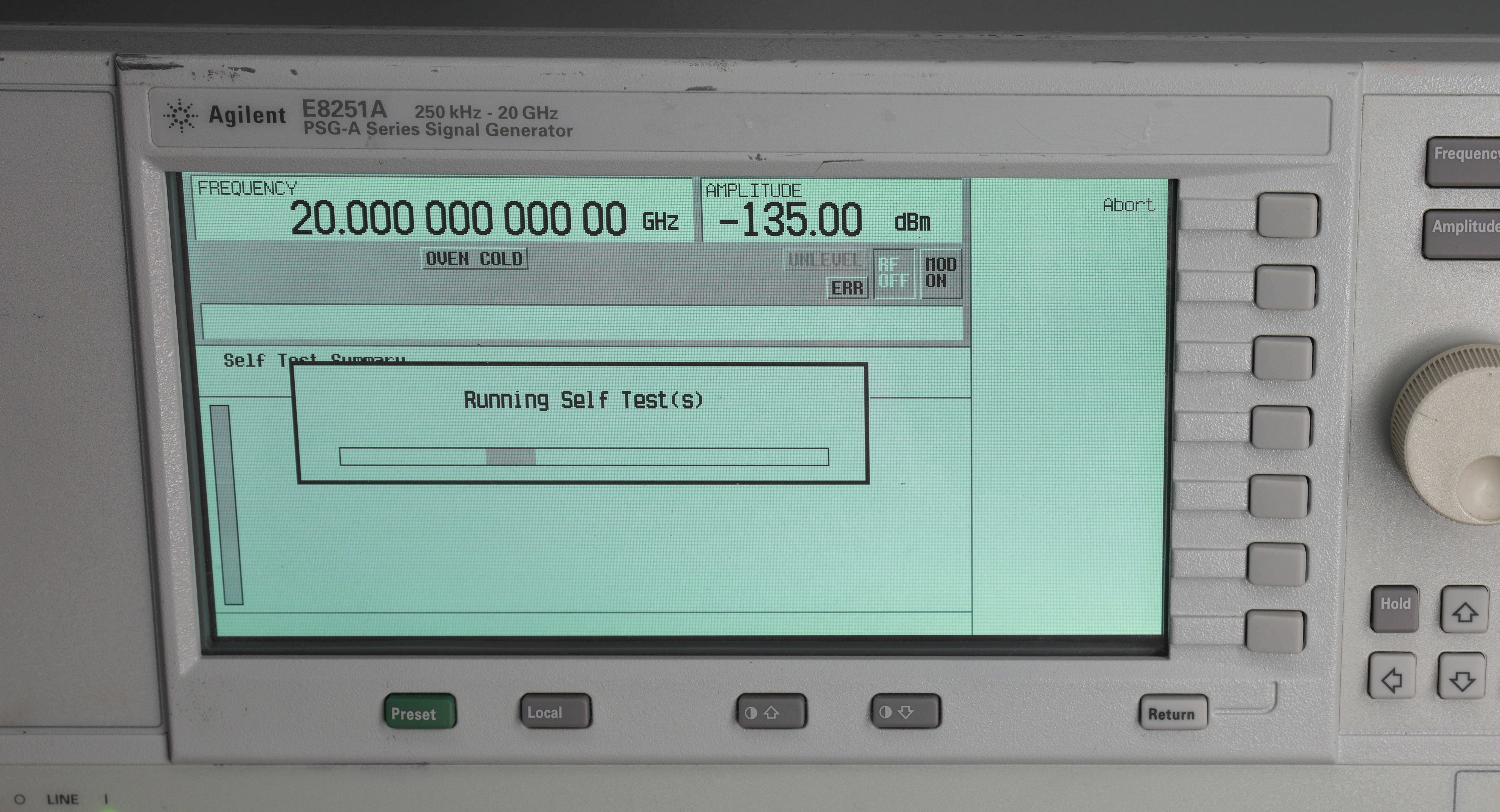
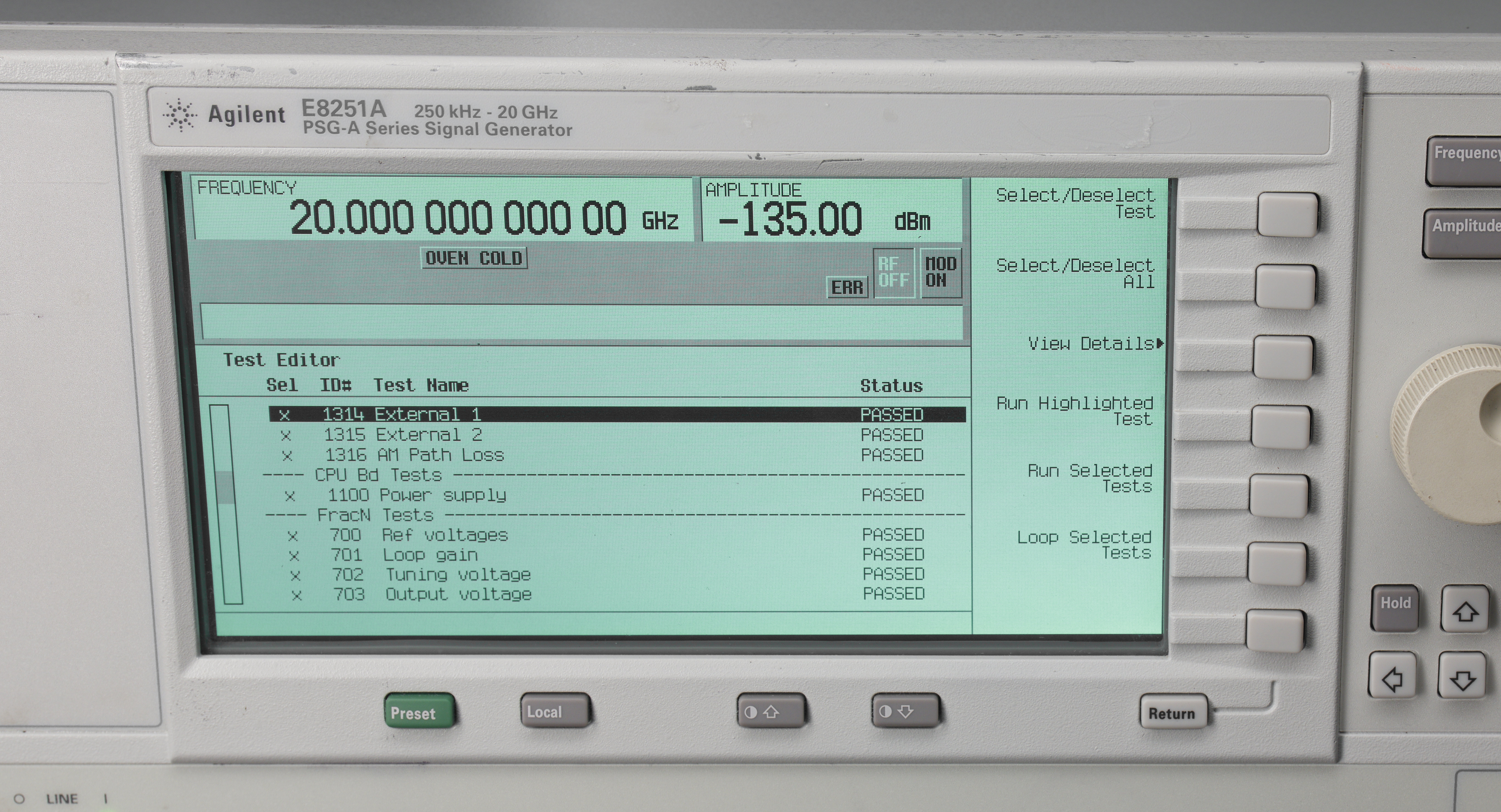
If I run BIST procedure we can get report with two fault codes in tests 901 and 902. Both of these related to ALC function of the generator. ALC means Amplitude Level Correction and is responsible for accurate RF output level at any signal programmed by user.
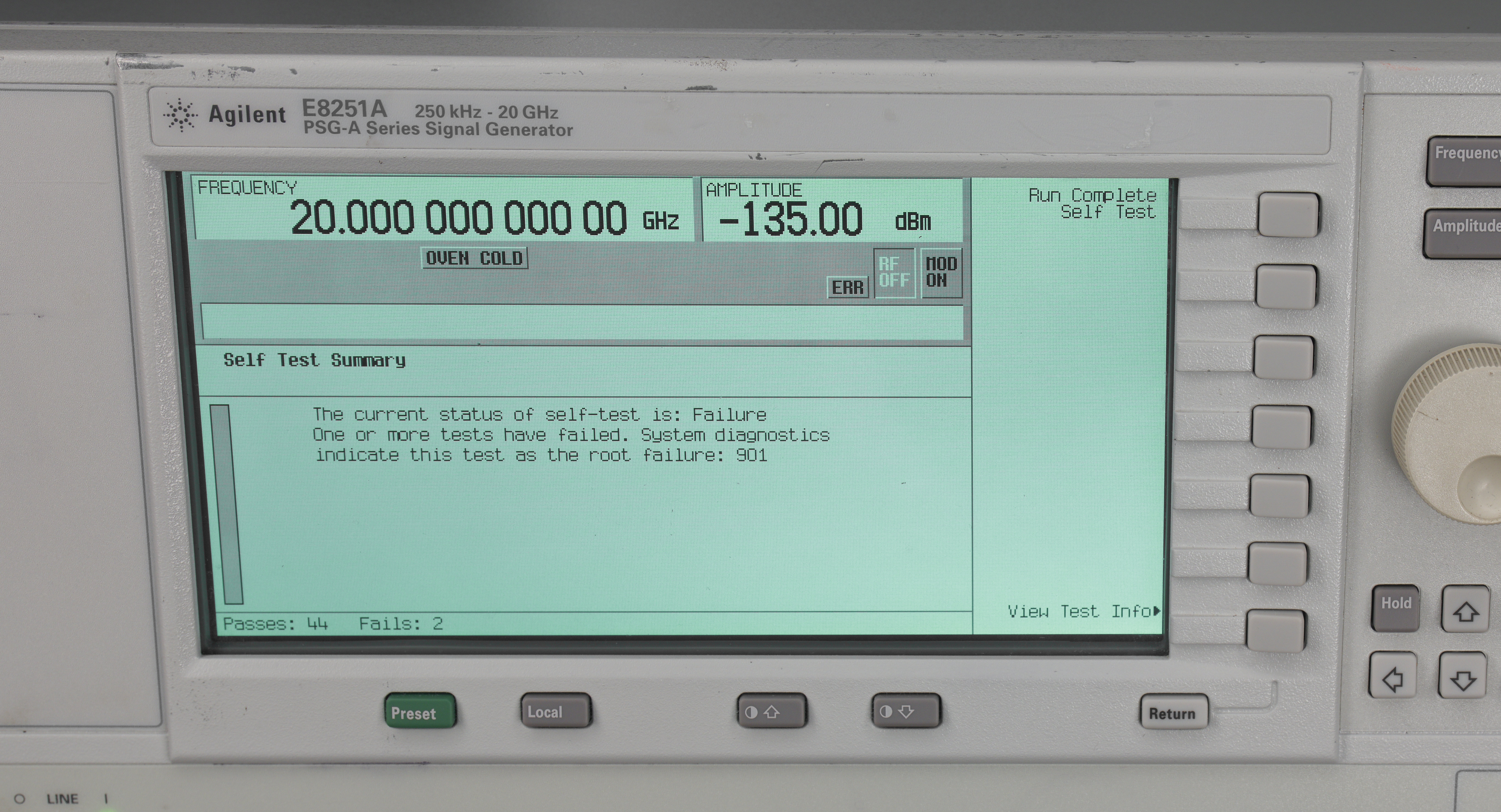
Oven cold message is not a problem, since photo was taken just after power up. These generators come with standard OCXO frequency reference block and that requires few minutes to reach proper operating temperature after the first power up. This message goes away once temperature in the oscillator oven reached stable state.
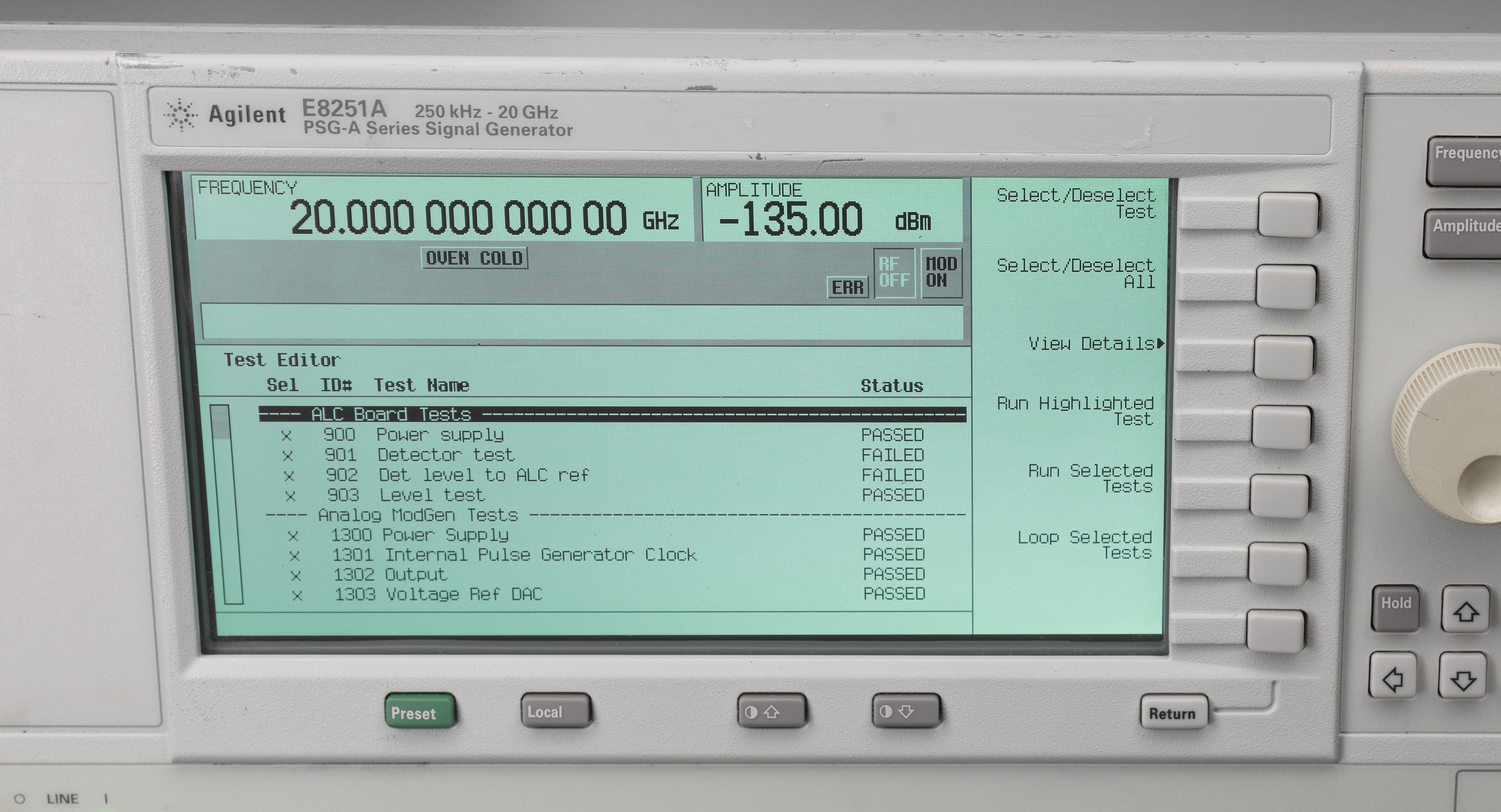
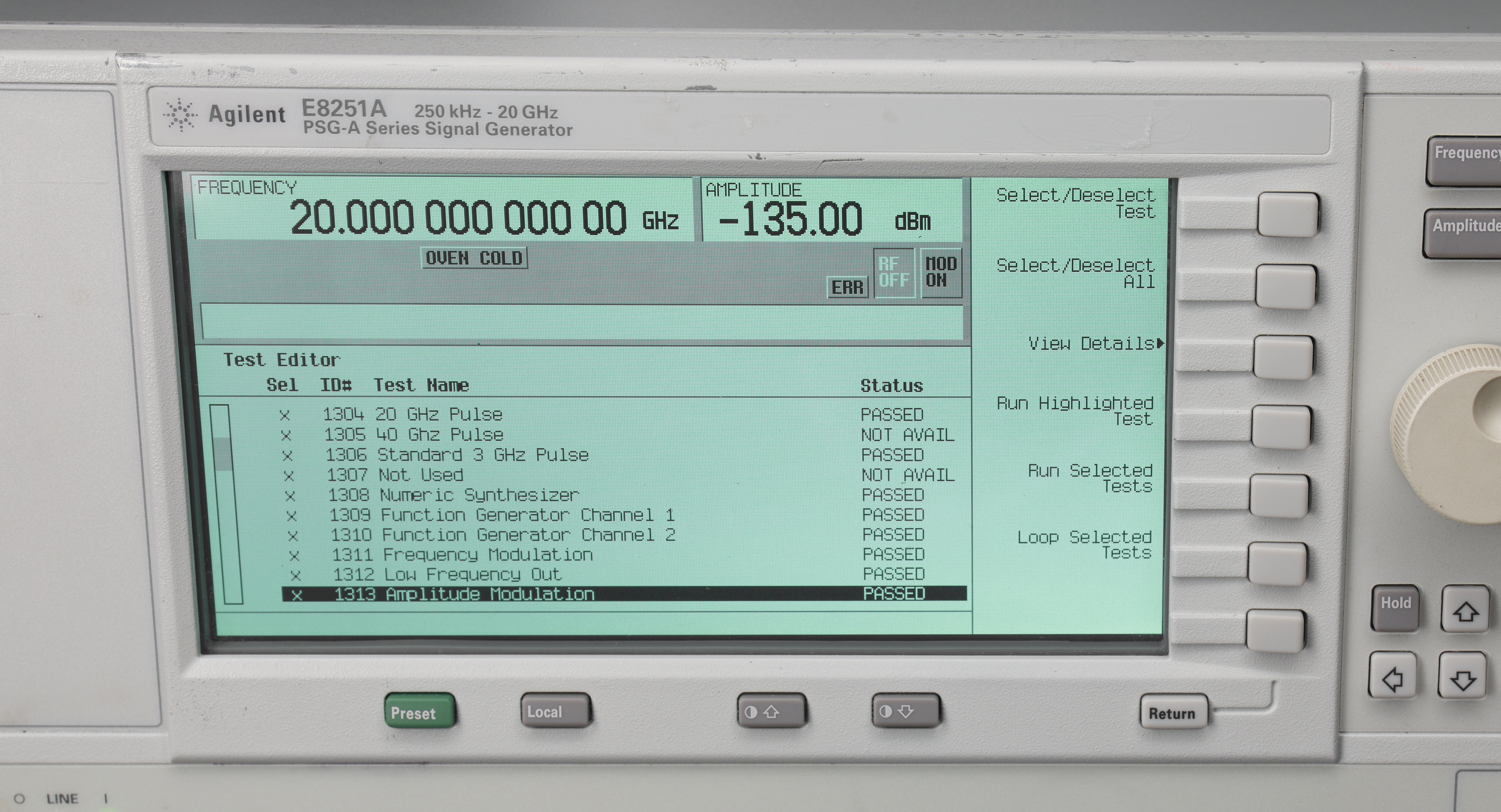
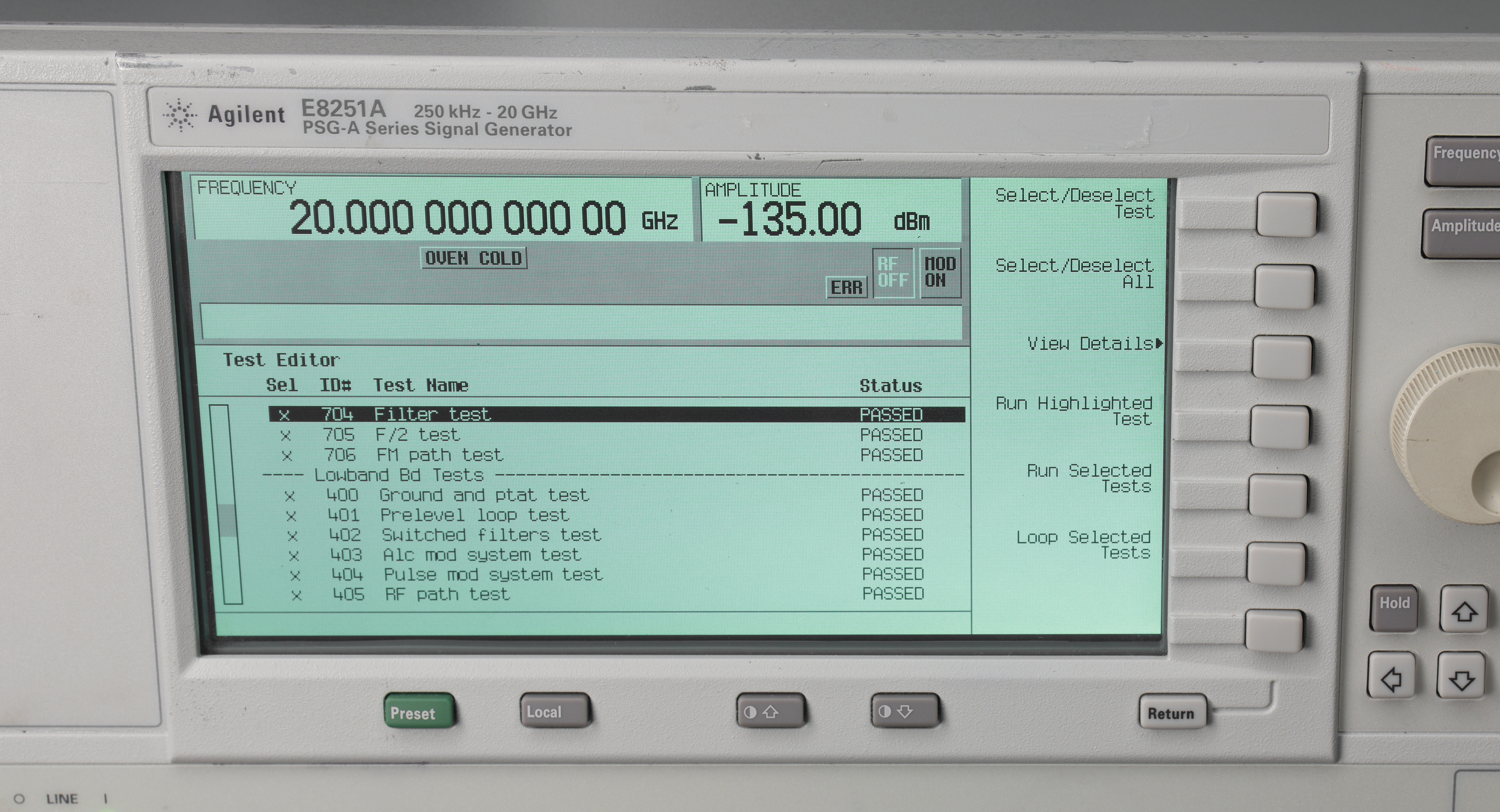
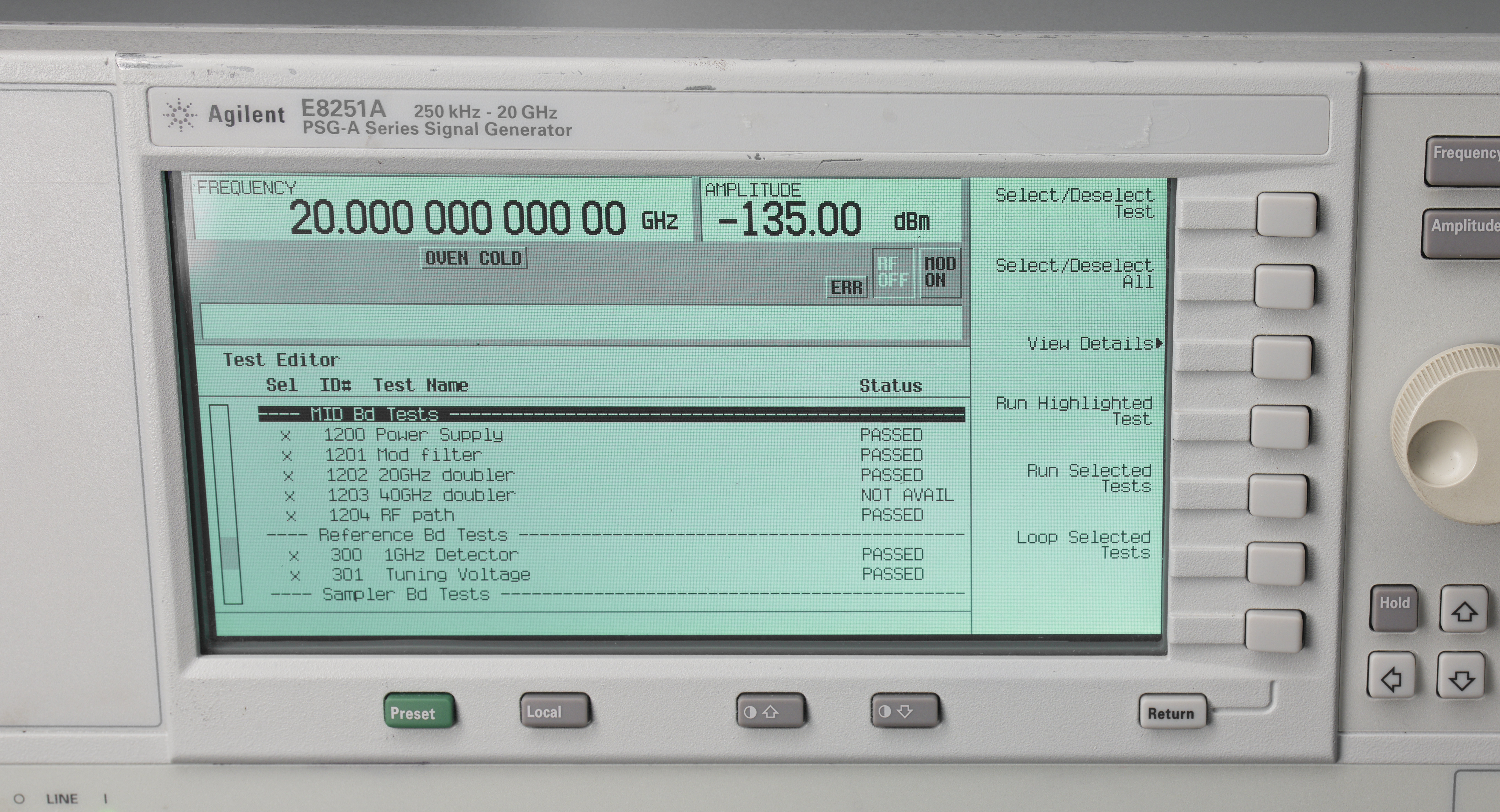
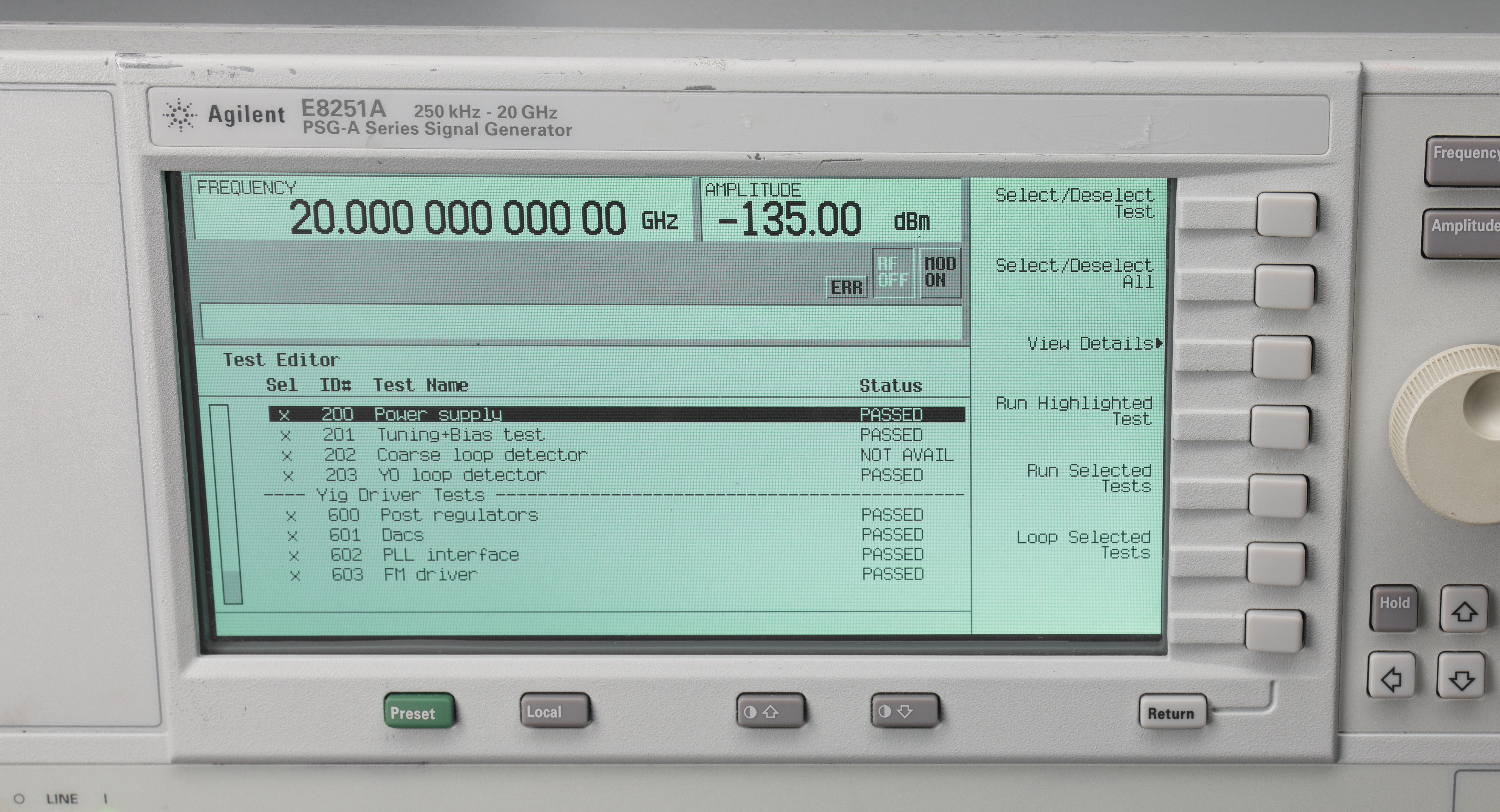
All other tests are completed without issues:
When I look at detailed points in tests 901 and 902 values out of tolerance as related to LowBand function:
According to service manual for newer PSG generators, ALC uses two separate blocks for different frequency ranges and domains sensing. The A23 Lowband Coupler/Detector block is connected to A10 ALC board and used for frequencies ≤2 GHz while the A24 Highband Coupler and A25 Highband Detector are used for higher frequencies >2 GHz.
Output port on this E8251A is coaxial bulkhead 3.5 mm RF , rated for frequencies up to 26.5 GHz. Higher frequency PSG generators utilize 2.4 mm and 1.85 mm RF connectors as well.

This will be interesting repair, since I don’t even have spectrum analyzer to measure anything above 3.6 GHz. I got RF power detector, Keysight U2000A that can measure power up to 18 GHz, but that’s about it :) Will need to get a proper 3.5 mm female to female adapter to act as connector saver and some good 3.5 mm or SMA cable for output connections and tests.
Plus RF equipment is very very far from my usual domain of work and I have only basic understanding how many of radiofrequency components and circuits operate. We are in for a lot of learning here during this worklog. We can also ask good friends who are far more knowledgeable in these instruments if we run into some road-block later on. It might be useful to remember similar era ESG-DP repair/teardown article as well.
Teardown time and internal construction of E8251A
Opening the beast is easy, just get off the rear feet and side handle. Bottom side reveals lot of magical parts, access to backplane boards and RF rigid coax plumbing. Be careful moving the opened unit around and avoid applying any physical pressure/stress to these rigid coaxial lines. Rigid tube coaxial is used to maintain the stable dimensions for high frequency interconnects and provide good long-term calibration accuracy. As signals frequency go higher even small minute movement of typical coaxial cable affect and change dielectric properties and amplitude/phase behaviour. That’s why you often see very bulky cables with many metal layered protection shields with ruggedized bulkhead connector assemblies used in high frequency RF equipment.
Top is protected by aluminum shield cover with helpful label, indicating location of various boards and connectors. It is always good to see some block diagrams and helper labels on equipment to aid service and repair. Older HP gear was particularly famous for good repairability and service-friendly designs, which earned a lot of praise from owners and engineers. Making test equipment field serviceable help a lot for long-term manufacturer reputation. Many engineers who got positive experience with previously aquired and well cared equipment are happy to continue investing and buying new products from well respected manufacturer. Access to parts and service like calibration/certification from the original manufacturer is a win-win situation for both user and company, since that can generate additional business while keeping customer’s fleet of equipment in operation over many years. That is one important thing that small unknown vendors don’t have much ability to offer and what can justify higher initial cost of famous branded equipment.
Removing cover reveals bunch of modules and boards in their compartments. Different options PSG might have additional hardware stuff installed, but our base E8251A unit has just what is shown on the photo. Mechanical attenuator is indeed present, large black box in the front corner.
Right away we can identify high band A25 detector (little coax bobbin thing with a label). It is attached to a blue box module which is A24 Highband Coupler with output going directly into mechanical attenuator block. The metal boxed module next to attenuator is yet another A23 module that is a fault suspect in this generator. It might be a big challenge to fix that, if some magical custom Agilent part is dead in it or if it has magical wire-bonded bare die stuff inside.
Repair and troubleshooting process
First I can check the easy bits, power supply rails and stability. Easy to measure with oscilloscope or a good benchtop multimeter, such as Keithley 2002.
All power rails are running good with small ripple and measured well within tolerance by DMM. No easy fix there.
Next we can test output of high frequency detector. For this PSG was configured to 10 GHz signal with +20 dBm output, RF on and ALC mode OFF. With such operation condition generator pushes signal via high frequency signal path and we should be able to measure DC voltage output of A25 detector with a simple multimeter connection.

And indeed we get some good reading, -0.307 VDC, which is somewhat in range that Agilent manual suggests it should be (-0.295 V). If output is off or frequency is set to 1 GHz DMM reads close to zero volts at the output. I think this confirms that high frequency detector works. Now let’s take a look on A10 board itself:
E8251-60005 ALC A10 board
In ALC leveling turned on (closed loop operation), the output level is detected by sensor and a DC voltage fed back and compared to a reference DAC voltage. The output of the comparator controls the modulator drive current, which controls the RF output power level. When the detected and reference voltage levels are the same, the modulator drive current remains constant. When the detected and reference levels are not the same, the modulator drive current changes, causing the RF output power to increase or decrease until the reference and detected voltages are the same. This way amplitude of output RF signal can be precisely controlled and maintained by using a programmable DAC block.
A10 ALC Board has row of SMB (?) connectors on top for detectors input and 20/40 GHz modulator circuitry. Interface to backplane is done with two multi-pin headers. Board overall looks bit dusty but in good condition, no charred or obviously blown parts. There are no reference designations for passives and quite minimal test point markings. Sadly I couldn’t find CLIP or service manual specific for this older E8251A Agilent generator model. I would appreciate if somebody has a copy/backup somewhere they could share?
Back of the board has just some decoupling passives, lone U417 opamp and few bodge-wired transistors. Board looks like 4 or 6 layers at most, light on copper.
Close-up on input section where various detector signals come in:
- J3 connector is the input for high-frequency ALC detector
- J5 connector is the input for low-frequency ALC detector/coupler
- J4 connector is for the external ALC detector/sensor
- J303 is SMI IN
- J201 is 20 GHz modulator connection
- J202 is not connected to anything in this PSG-A as it’s only 20 GHz model, not 40 GHz.
Looking at the parts, I can see that all of the stuff is just commercial chips, still available on Digikey.
Q1 is rather expensive dual JFET pair from Linear Systems LS844. U3 and U4 are solid-state switches from ADI – ADG451BR. I think these are responsible for switching various detectors for the ALC operation. From the block diagram I can learn that A10 has three possible inputs, with additional amplifier block used for high band and external ALC detector. Low frequency detector signal is routed straight to the multiplexer and then into ADC MUX directly or go to the whole bunch of circuitry starting with Dual Slope Log Amp, perhaps all used for modulation filtering/operation.

Orange block is a large A10 PCBA inside of the instrument, containing all the low-frequency components and control. Red attenuator block is option 1E1, right before our RF output to the front panel. Blue A30 module is modulation filter on RF deck, while cyan A23 block is the suspect LowBand coupler/detector unit.
Testing A23 LowBand coupler/detector unit
Service guide for newer E8257/E8257 generators suggests following test procedure for low frequency unlevel ALC troubleshooting:
If the unleveled problem only occurs between 250 kHz and 2 GHz, the problem is most likely the A23 Lowband Coupler/Detector.
a. Checking the A23 Lowband Coupler/Detector:
- Set the signal generator to 1.9 GHz or an unleveled signal generator frequency.
- Connect a power meter or spectrum analyzer to the A23 Lowband Coupler/Detector output.
- Set the signal generator to 1 GHz. Using the RPG, adjust the amplitude level so the detected voltage on cable J5 of A10 ALC (W14) is -0.117 VDC. Using a power meter, measure the signal level at the end of the cable going to J3 of A30 Modulation Filter (W27). Use Table 2 to determine the expected power level. If the power can not be adjusted to this level, troubleshoot the RF path.
| Settings | Expected Power Level |
|---|---|
| 1 GHz, DC voltage on cable J5 to A10 is -117 mV | +2.3 dBm ± 0.5 dBm |
- If the problem is at some frequency other than 1 GHz, repeat the above step using the problem frequency. The dB p–p variation from 250 kHz to 2 GHz should be <2 dB.
- If the DC level is bad, replace the A23 Lowband Coupler/Detector.
- If the signal is good, replace the A10 ALC.
RPG is a control knob on the front panel, and not a rocket-propelled grenade. Following this procedure, I’ve tried various frequencies from 500 MHz to 3.2 GHz, and observed signal at the output of A23 module, which was present but incorrect amplitude. Anything over 3.2GHz was absent as generator use different signal path for high frequencies.
But DC detector output never went above 50-55 mV DC at highest, and never reached to desired -117 mV DC. This suggests again a faulty A23 assembly. Time to remove module from PSG and take a look inside, if we can investigate further.
SMA connector close to interface connector side is RF output which goes to RF IN at A30 modulator/filter, using thick rigid coax cable. Input to A23 is on the opposite side.
Removing few screws and opening up clam-shell shield covers reveals internal board with all the magical RF components.
Now we can photograph the board and admire interesting layout and design.
Back side also filled with parts. PCBA part-number is E8251-60010. This board was manufactured around year 2001.

Detector itself is placed small isolated island near the RF input port.
I’ve measured output rail from U103 and it was recorded at +4.94 V, which is OK for this LM78L05ACM linear regulator. I couldn’t see anything out of place on this module.
Day 2 – testing modules and blocks
Next step were the tests using external generator attached to A23 input. For this I can summon help from Fluke 9640A RF reference source and Agilent N9020A MXA to do some measurements. Fluke 9640A output head was attached to input of A23 module and A23 output was routed to MXA analyzer for signal measurement while Keithley 2002 measured DC detector output that was attached to A10 ALC assembly.
Testing DC voltage output from detector module with applied external RF signal at 1 GHz revealed good levels tracking.
| 1 GHz signal power | Measured DC voltage output from A23 |
|---|---|
| -30 dBm at 1 GHz | -0.073 mV |
| -20 dBm at 1 GHz | -0.550 mV |
| -10 dBm at 1 GHz | -5.3 mV |
| 0 dBm at 1 GHz | -52.3 mV |
| +5 dBm at 1 GHz | -153.9 mV |
| +8 dBm at 1 GHz | -282 mV |
| +10 dBm at 1 GHz | -414 mV |
| +15 dBm at 1 GHz | -962 mV |
| +20 dBm at 1 GHz | -2.033 V |
I’ve tested various RF power points at fixed frequency 1000 MHz and recorded DC voltages from detector that looked very reasonable to me. The loss of RF power travelled thru A23 coupler/detector block was measured around 1-2 dBm, which is within limit <3 dBm outlined in service manual for PSG generators.
Fiddling with RF power level a bit on 9640A makes bad self-test 901 and 902 pass with flying colors. This tells me that A23 and A10 are operating properly and issue is earlier in the signal path. So these tests conclude that A23 module is operating properly, and we can move onto RF source for low band, which is A8 Output PCBA.
A8 E8251-60046 – Low Band Output PCBA
Board is enclosed in heavy cast metal shields from both sides. All interface and RF connections are on the bottom insert side of the card. There is alarming orange sticker on this board that says “Retest”. This board is a common cause of “UNLEVEL” errors in ESG and PSG generators, as supported by evidence of various online posts here, here, here.

Opening the board is straight-forward after removing 17 torx head bolts. Need to be extra careful with these shields as they have channels for squiggly metal contact helix springs to improve the RF shielding. Best not to touch these as they can come loose and they can be hard to get back in place once disturbed.
Output connector J6 is coaxial SMB male near the center of the board edge. Let’s take a look on block diagram for output board. I’ve looked at connector and half of the female receptacle was missing.
This connector looks like SMB but it is different type. Thanks to this message by Razvan Popescu we can find the original connector type, which is 85_1023-C50-0-1/111_NE from Huber+Suhner.
This is 1.0/2.3 type connector, rated up to 4 GHz and pretty expensive available from Mouser at 43 USD. HP/Agilent/Keysight connector part-number is 1250-2549. For now I just desoldered damaged connector and moved J5 connector to J4 position instead. J5 from A8 in my E8251A PSG is not connected to anything. As alternative one could probably use a cheaper 8 USD Rosenberger 45K201-400L5 connector which has very similar dimensions and rated from DC to 6 GHz.
This board is responsible for pulse modulation, amplitude modulation and generate under-range frequencies under 250 MHz. Pulse modulation (RF pulsed on) is achieved by applying +5 V DC to the pulse circuitry on the A8 Output. +5 V DC turns the RF signal on; removing the +5V DC turns the RF signal off. Frequencies under 250 MHz are the result of mixing the A6 Frac–N RF signal with a 1 GHz signal from the A7 Reference and using the difference between the two signals for the output. The A8 Output signal passes through the A23 Lowband Coupler/Detector to the A30 Modulation Filter and goes to the output of the instrument.
This board receives filtered RF signal from 250 MHz to 3.2 GHz from the A6 fine-tune Frac-N assembly, filters it some more and maintains the level with own ALC modulation block. It feeds preleveled detector output back to Frac-N A6 and provides internal signal output to two possible paths:
- Signals with frequency from 250 MHz to 3.2 GHz are passed to output PA(power amplifier) to generate >+17 dBm (std) or >+20 dBm (1EA option) signal out.
- Signals with frequency under 250 MHz are switched to mixer with 1 GHz LO with some filtering and amplification, before going to the same output PA.
This can give us two possible test scenarios, one for frequency under 250 MHz and one for signals above 250 MHz. Since our generator has option 1EA, we should expect +20 dBm at the output port J6 in either case. Looking at the board I can see some flux residue left on the board around few components:
- Q2600 – output JFET amplifier, in SOT-89 package with marking H1 and two red paint dots.
- Z220 – white packaged RF part with marking MCL 0 119 ADE-12MH. It is MiniCircuits SMT frequency mixer from 10 MHz to 1200 MHz
- flux marks near 0603 passive pads close to U920 LM393D comparator
- Q920 IRF9020 FET in DPAK package
- U50 chip I/Q modulator option unpopulated circuitry
These HFET amplifier transistors are now obsolete 0.05GHz to 6GHz, 0.5WATT GaAs HFET from RFMD, P/N SHF-0189. RFMD was acquired in the past by TriQuint which is now part of Qorvo. I recognized Qorvo name because of Mike Engelhardt who is well known to me from his development of freewave SPICE simulator such as LTspice.
Maybe modern replacement for this obsolete HFET amplifier could be Qorvo TQP7M9103 which is already in NRND status and will get obsolete soon. This part however is a fully integrated amplifier and has maximum output +5 VDC bias voltage, making it impossible to use as direct replacement without circuit modification. I’ll try to source original SHF-0189 parts from secondary market if indeed one of these faulty on my board.
This board somewhat very similar to old E4400-60003 from E4436B ESG-DP output assembly, mostly reusing same components and blocks:
ESG board used different amplifier stages for RF signal path but many of the other parts are precisely the same and even layout is mostly same. Close-ups on various sections to PSG-A board.
Looking at layout and components placement we can determine that signal travels from corner RF connectors up along the right edge of the board, reaching Q1000 JFET amplifier, going thru sections of various frequency bands filter, reaching second stage amplifier around JFET Q1400, going further towards 3rd stage around Q1800 and then going down around center the board via 4th stage JFET amplifier Q1900 and last stage JFET Q2600 before reaching AC coupling capacitor and output connector J6. There are some switches and lot of diodes along this signal paths which leaves us with a variety of suspects to troubleshoot and test. Our friend TheSignalPath covered this board in this video more than 11 years ago with very good detail depth, done during his ESG generator repair. In his video one of these SHF-0189 amplifiers was bad, causing very weak signal, so perhaps we have similar issue in my PSG as well?
Neon Kev also posted his repair experiences with much newer E8257C PSG in this video, with a look on new A8 PCBA. We can see from this video that newer PSGs have significantly different physical layout while overall architecture remained the same. I like his extension approach for much easier probing of the parts on the board, perhaps I’ll replicate something similar. Back to the block diagram study, we can try few simple tests to try narrow down the issue.
1. Test A8 output RF power of signal below 250 MHz, for example 100 MHz. If level is high and good, then issue is in mixer bypass path, and output PA is good.
2. Test A8 output RF power of signal above 250 MHz, for example 500 MHz. If level is high and good, then issue is somewhere in the mixer block for lower frequency, and PA is good.
3. If A8 output RF power is bad for either of the frequency, then there is a problem in output PA or with any of the components prior to the mixer block.
It’s possible to use active probe for testing signals with frequencies around hundreds of MHz. Lucky for me, I’ve repaired few Tektronix TDP1000 which should fit the bill just fine, coupled to Tektronix DPO7104C. Another item to note – self-test items related to A8 diagnostics are all passing good, this means that preleveling around input circuitry for Frac-N signals is most likely working correctly, otherwise PSG would complain about that. But perhaps we can just quickly check voltages around HFETs and see if any of them are out of the expected levels. For this I’ve made quick ribbon cable extender to connect A8 board to the mainboard (without RF coaxial connections) to make it easy probing around when PSG is powered up.

Measurement result revealed questionable voltages around Q1000 HFET amplifier. This fault is very similar to what happened in TheSignalPath’s video about ESG-D generator repair.
| Measurements | Gate (pin 1) | Drain (pin 3) |
|---|---|---|
| Q1000 SHF-0189 | +0.17 V | +0.03 V |
| Q1400 SHF-0189 | -0.99 V | +8.20 V |
| Q1800 SHF-0189 | -1.00 V | +8.26 V |
| Q1900 SHF-0189 | -1.01 V | +8.19 V |
| Q2600 SHF-0189 | -1.00 V | +8.20 V |
Lifting L1000 inductor to isolate bias rail for Q1000 JFET confirms good +8.5 V at the inductor side. This means that HFET is damaged and shorting the rail to the ground. Whatever residual RF signal is amplified by later stages that work and shows up at the output of A8 as very weak signal. I’ll wait until replacement HFETs arrive and try to replace Q1000, to investigate if this fixes all issues in this PSG.
Little SOT23-3 devices scattered nearby are RF pin diodes, used a switches. Ones marked G4V are HSMP-3894 and others with G2Y mark are HSMP-3892. These were manufactured by Broadcom and are obsolete now, no surprises there.
HFET Replacement options and tests
My usual strategy is to find exact part for replacement to keep the original factory condition of the repaired instrument. But it’s not always possible, especially for older gear as parts have limited production lifetime and might be custom special limited order stuff. I looked into few E4400-60003 ESG generator output boards with hopes to find one with these old SHF-0189, but wasn’t lucky. All boards I got had golden ceramic/metal packaged HP custom amplifiers. That amplifier could possible made to work as replacement but it would be pretty ugly on the PCB due to different pin mapping, biasing and whatnot else.
Another plan B was to steal a newer HFET amplifier from broken Agilent N5182A MXG signal generator. As we learned before in N5161A repair it’s mainboard has some RF amplifiers in signal path, looking quite similar to our suspect TO89 part. Closer inspection revealed few candidates:
See those TO89 devices on a cute heatsink pucks soldered in? One of them is labelled Q2700, hinting of possible HFET type. The top package markings on two of devices are FP21G N678-2 and FP11G M551-1. Little bit of detective work with SMD part-number decoder index tells us that these two parts are:
WJC FP1189 0.5 W HFET, +40 dBm IP3, 50 MHz to 4000 MHz, 2.7 dB NF
WJC FP2189 1 W HFET, +43 dBm IP3, 50 MHz to 4000 MHz, 4.5 dB NF
I’ve summarized some main parameters in the table below for comparison with original SHF-0189 component.
| Parameter | Units | SHF-0189 | FP1189 | FP2189 |
|---|---|---|---|---|
| Maximum power | W | 0.8 W | 0.5 W | 1 W |
| Operational bandwidth | MHz | 50 to 4000? | 50 to 4000 | 50 to 4000 |
| Small signal gain | dB | 20.1 | 20.5 | 18.5 |
| Maximum stable gain | dB | 23.3 | 24 | 24 |
| Output P1dB | dBm | +27.2 | +27.4 | +30 |
| Output IP3 at +8Vdq | dBm | +40 | +40 | +43 |
| Noise figure | dB | 3.2 | 2.7 | 4.5 |
| Drain bias | +8Vdc at +160 mA | +8Vdc at 125 mA | +8Vdc at 250 mA | |
| Transconductance, Gm | mS | 198 | 155 | 280 |
| Pinch off Voltage, Vp | VDC | -1.9 | -2.1 | -2.1 |
| Thermal resistance | °C/W | 80 | 68 | 35 |
As I could see from the glossing over datasheets, FP2189 is somewhat close to SHF-0189, so I’ve decided just to swap the part and see what happens. Perhaps real RF circuit design would do a lot of analysis and study on biasing networks, all those resistors, inductors and carefully designed in capacitances to guarantee optimal operation point of the replacement transistor. But to me all that is still a black magic and I’m curious if generator would actually work in general first. So with help of powerful ERSA ICON 1 iron I’ve removed FP2189 from MXG board and soldered it into our PSG’s A8 output assembly, replacing original suspect Q1000 SHF-0189.
All the biasing was kept original, zero changes done to those components. Here’s the schematics of this busy block as it is now:
After chip replacement A8 was sealed back into it’s shields and installed back into the instrument. Everything booted up normally and on the first try I could set 100 MHz output signal and did not see any “Unlevel” fault messages! Promising start. “ERR” label on the screen is shown because internal OCXO was not warmed up just yet, it’s normal and goes away after 5-10 minutes of generator running.
Good leveled output was reported with power level all the way up to +23.0 dBm, which is great. Running self-test diagnostics also passing now with flying colors.
Looking into detailed 901 and 902 ALC test sections show all numbers within the expected high/low margins.
Finally I’ve captured installed board hardware information, perhaps could be useful for somebody else in future:
And always useful too take a look on some other boards in E8251A while we are messing inside.
A5 – E8251-60043 Sampler PCBA assembly
TBD
A6 – E8251-60044 Frac-N PLL assembly
This board is another weak point of these ESG/PSG generators as it has custom HP/Agilent/KS RF component that is known to develop faults. This board is responsible for fine frequency signal generation, using fractional N PLL. Output from this board has signal in range from 250 MHz to 3.2 GHz and fed to A8 output assembly for further filtering and amplification.
TBD
A7 – E8251-60073 Reference PCBA assembly
TBD
A9 – YTO driver board assembly
TBD
A9 board is responsible for driving the YIG-tuned oscillator which require quite a bit of power to operate. Hence it has large heatsink with some juicy TO-220 power components, precision DAC/ADC and various control circuitry around it all.
A11 – Pulse/Analog Modulation Generator
TBD
A18 – CPU board
TBD
Performance tests after repair
For limited benchmark after repair I’ve connected this freshly repaired Agilent E8251A PSG-A to my modest 3.6 GHz Keysight N9020A MXA spectrum analyzer, using 60” Gore Phaseflex N to N cable with set of 3.5mm adapters and short microcoax cable. PSG was configured for frequency sweep from 10 MHz to 3700 MHz at fixed +0 dBm power level. MXA configured to capture max hold trace at 1001 points.
Result screenshot of the sweeps. Vertical scale is 0.2 dB/div. I think this is good result, given the long RF cable and number of adapters? Perhaps some day I could visit some friendly laboratory who has proper 26.5 GHz or faster spectrum analyzer to properly test this PSG-A operation all the way to the 20 GHz. Or perhaps there is some Python code for Agilent U2000A USB power sensor that could be used for flatness measurement up to 18 GHz? According to datasheet generator should be flat within ±0.8 dB up to 20 GHz.
I’ve also captured phase noise using internal function of my N9020A at two frequencies – 100 MHz and 1000 MHz, with 0 dBm output power. I’m not sure if these numbers are any good or not?
In datasheet phase noise for standard unit at 1 GHz signal is charted at -100 dBc/Hz at 100 Hz offset, while my MXA shows -88 dBc/Hz. Perhaps my result is worse because MXA and PSG are not syncronized and running off their own oscillators, instead of external precise clock like Rubidium atomic reference? Or maybe MXA noise floor is not good enough to test PSG? I don’t have any practical experience with phase-noise measurements here, perhaps someone can help with suggestions?
Summary and conclusion
Now this article come to desired conclusion, adding one more powerful and useful instrument into xDevs.com lab. This is highest bandwidth instrument we have in the lab to date, if one not count Leo Bodnar’s pulse generator capable of generating 28 ps rise time edges.

Instrument is now reassembled, cleaned up and labeled with mandatory xDevs tags, ready to serve on GPIB address 25. I’ll expand this article in future with more tear-down photos of other assemblies as well once I read bit more about what any of them do, to have better idea what to describe.
Overall this is fun project and was interesting to learn about. RF instrumentation is still a very much far out of our main scope of interest, but that does not diminish the interest in circuits and instruments evolved around RF domain of electromagnetic spectrum. In the modern world, RF signals and waveforms are everywhere around us, from the Internet, cell-phones or mundane microwave ovens. And even all the DC voltage metrology is in the end defined by the inverse AC Josephson effect, thanks to JVS cryogenic standards use as ultimate physical implementation of quantum accurate frequency to voltage DAC converter.
I’d like to give credits to my friend Alex for help and support in making this project possible. I can’t wait to put this powerful generator into proper experiment use in future. Discussion about this article and related stuff is welcome in comment section or at our own IRC chat server: irc.xdevs.com (port 4808, channel: #xDevs.com) or via traditional email.
Projects like this are born from passion and a desire to share how things work. Education is the foundation of a healthy society - especially important in today's volatile world. xDevs began as a personal project notepad in Kherson, Ukraine back in 2008 and has grown with support of passionate readers just like you. There are no (and never will be) any ads, sponsors or shareholders behind xDevs.com, just a commitment to inspire and help learning. If you are in a position to help others like us, please consider supporting xDevs.com’s home-country Ukraine in its defense of freedom to speak, freedom to live in peace and freedom to choose their way. You can use official site to support Ukraine – United24 or Help99. Every cent counts.
Modified: June 2, 2025, 5:20 a.m.