Intro
For a recent project I needed to measure some juicy kilovolts power supply unit. Typical multimeter is often rated to DC input up to 600-1000 V but if there is need to measure more than this it becomes a more involved engineering task. Typical method for DC high voltage measurement is to use external resistive divider with output then measured by traditional lower voltage multimeter or digitizer. In theory it sounds very simple but devil hides in all the details to make such a divider probe safe to operate by user while meeting performance parameters.
In this quick POW article we can take a look at old version of Fluke 80F-15 probe designed to measure signals up to 15000 V. It is older version acquired from ebay and in unknown condition. Modern Fluke 80K-15 looks quite a bit different but follows the same idea internally and functionally. MSRP cost for this probe from Fluke is $380 USD, not terribly expensive for the safety and confidence you’d need not to get electrocuted.
Design
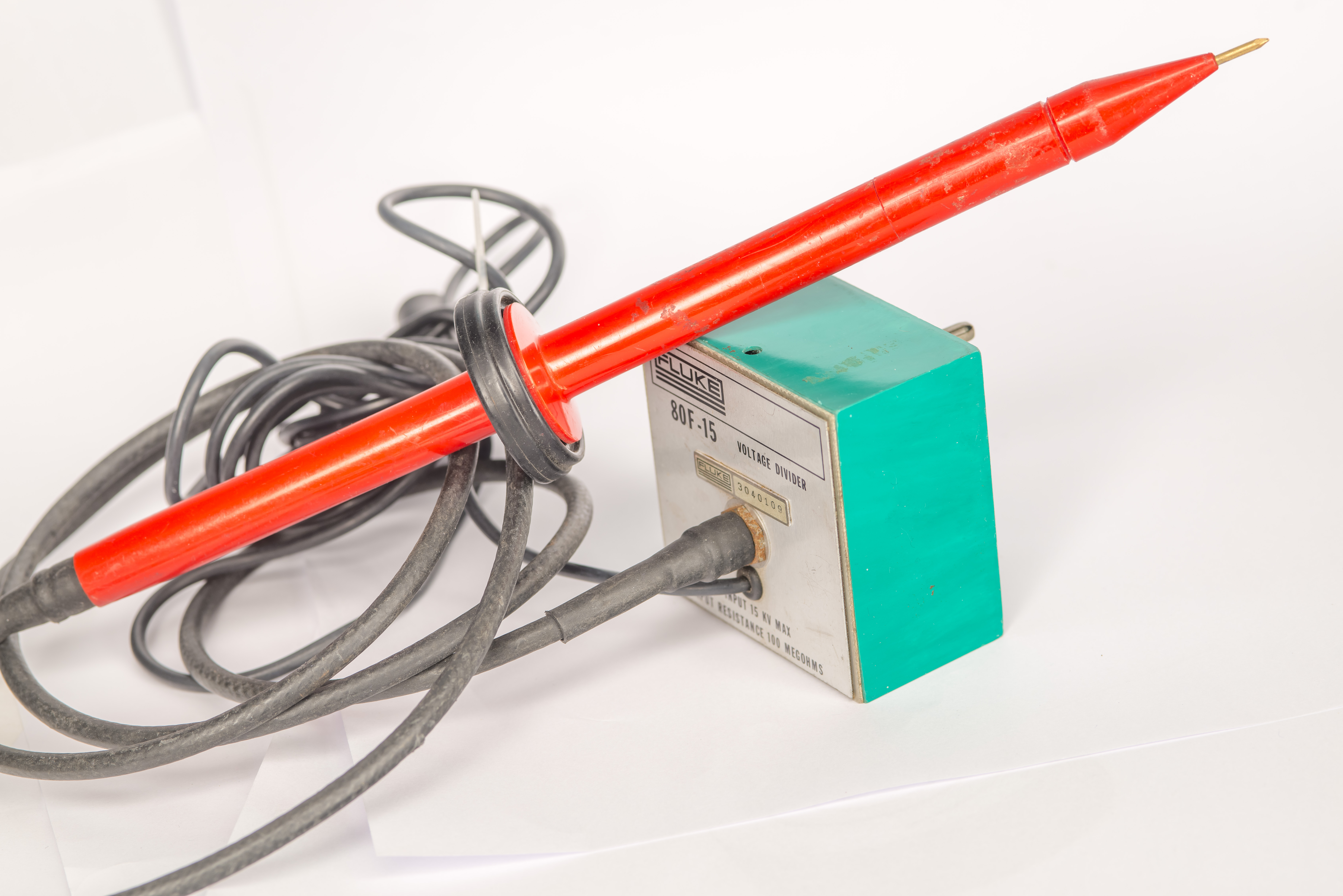
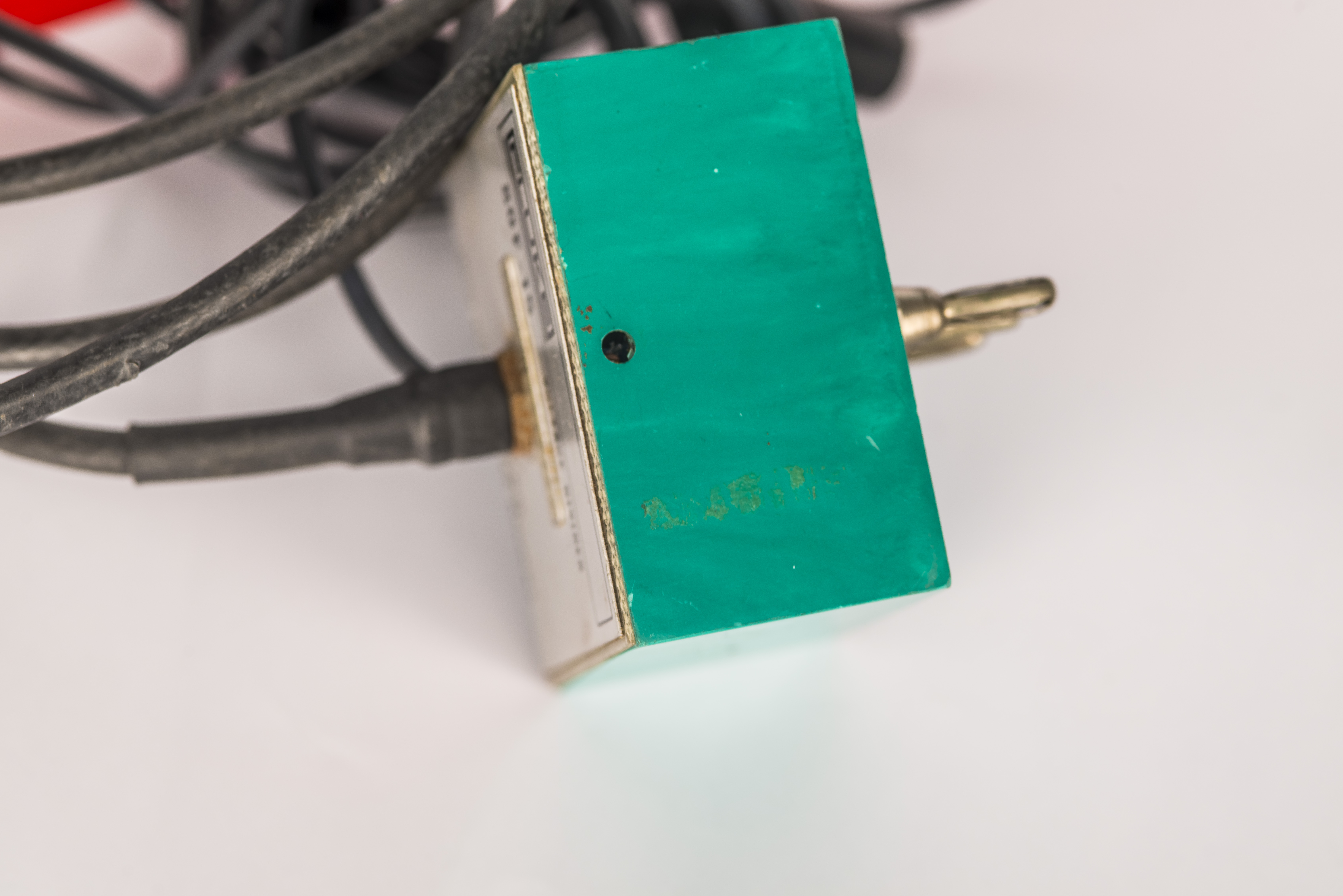
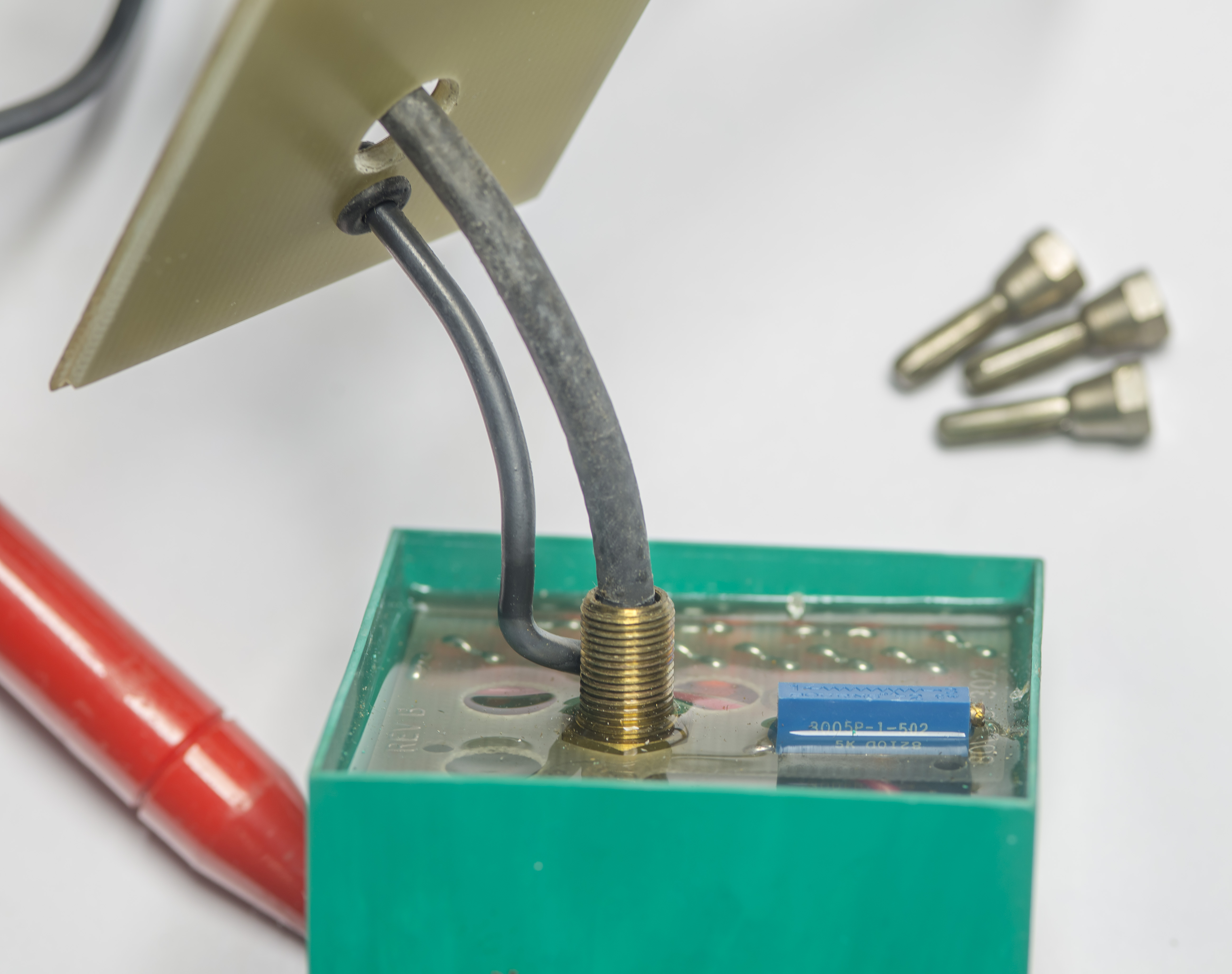
Probe has three main components – the bright red handle with input tip, classic Fluke teal box with meter interface and stiff high-voltage rated coaxial cable.
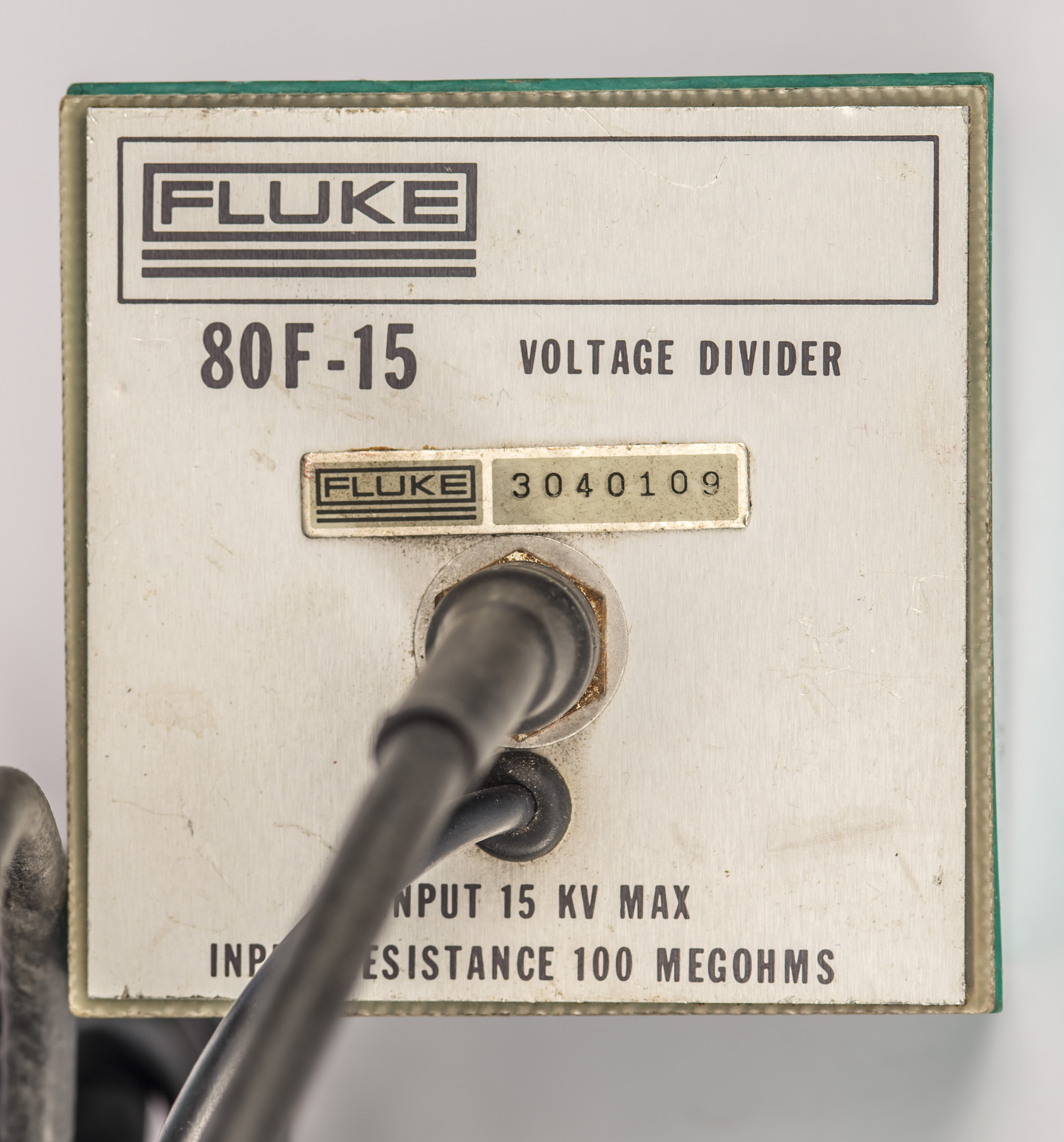
It has S/N 3040109 and label suggesting maxiumum 15 kV input and nominal input resistance 100 MΩ. There are two wires between two ends, coaxial for high voltage input and soft silicon grounding lead to complete the circuit. Keep in mind that these probes REQUIRE known and good termination at the output to form the resistive divider. Usually this is expected to be 10 MΩ which is commonly available on higher ranges of handheld and benchtop multimeters.
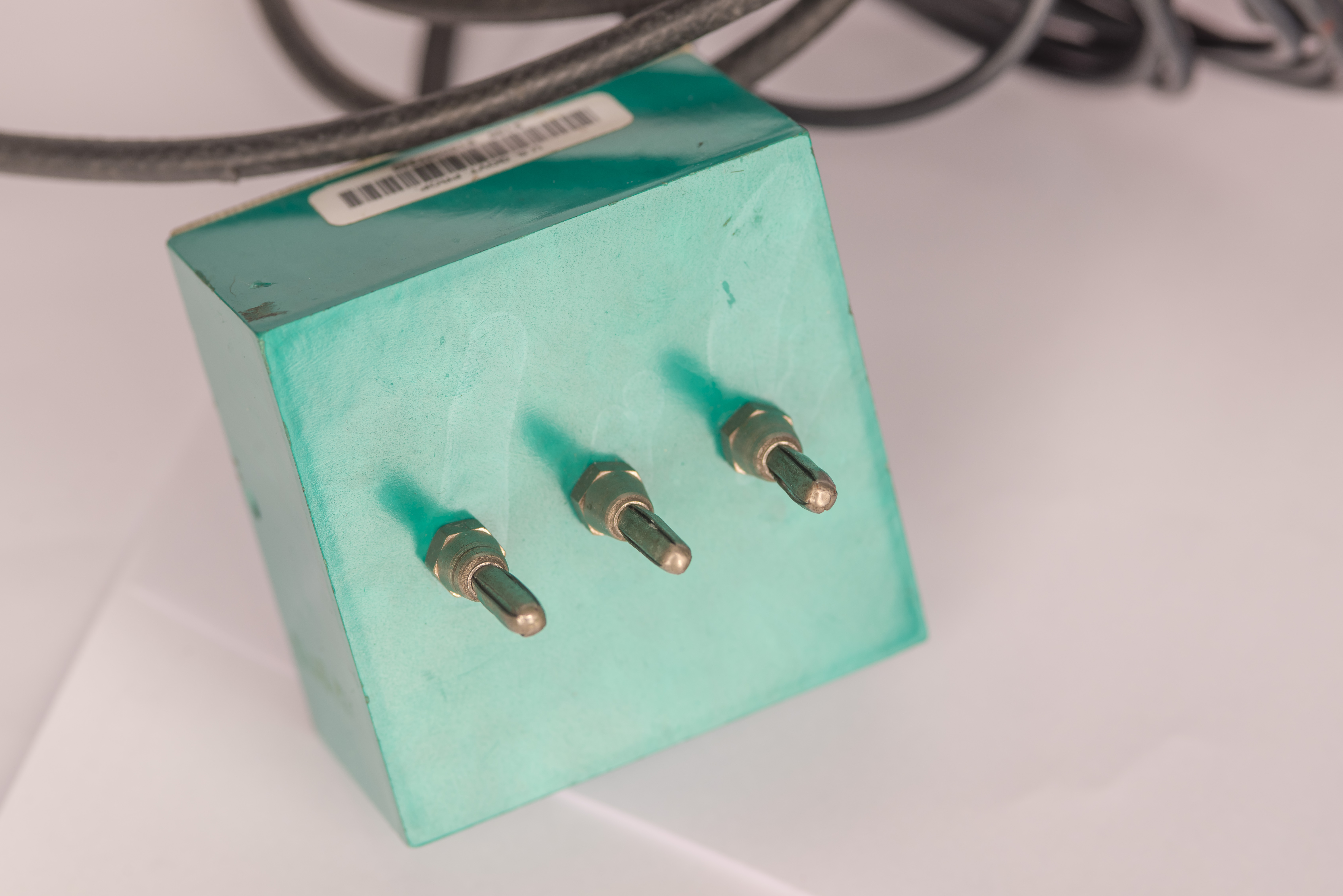
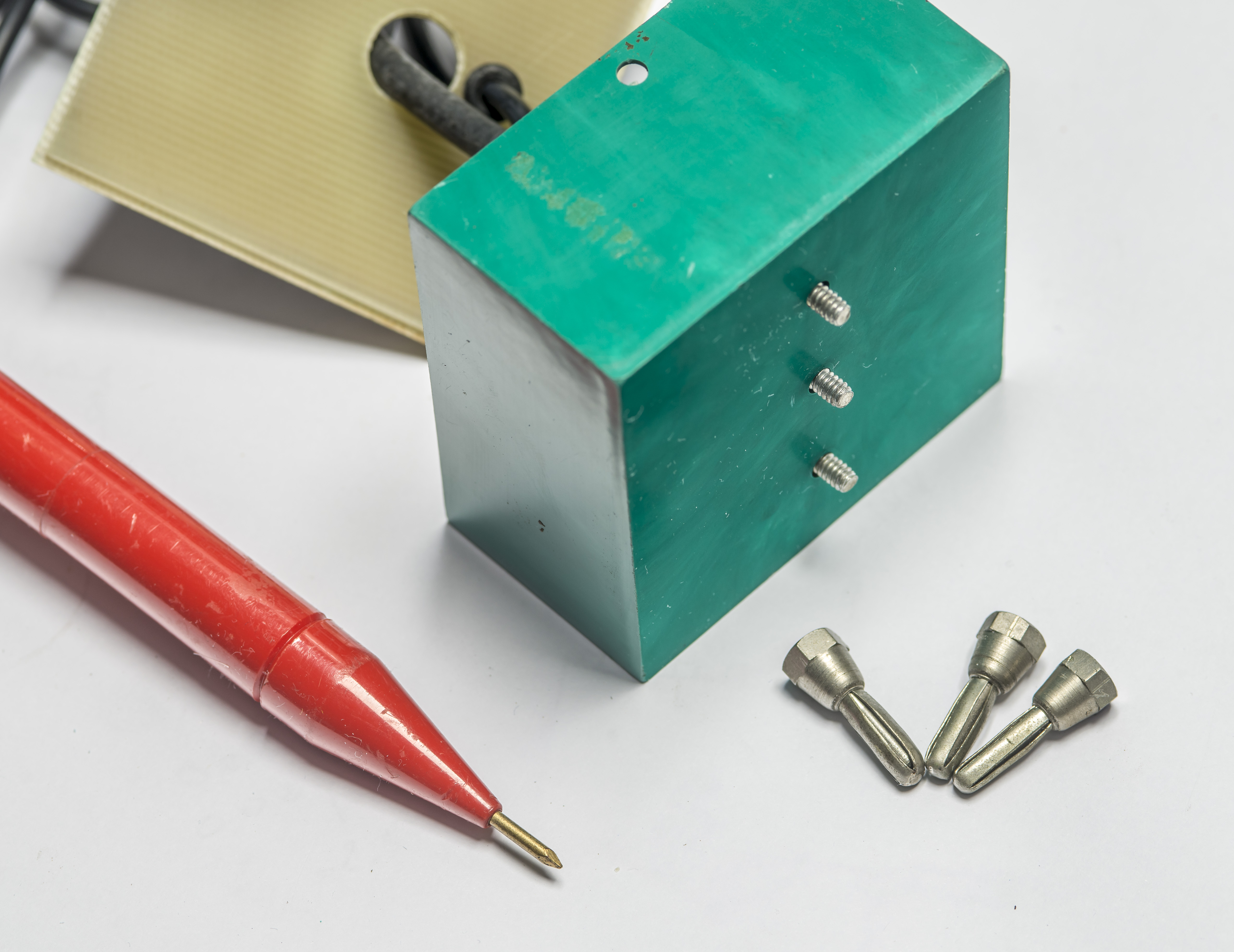
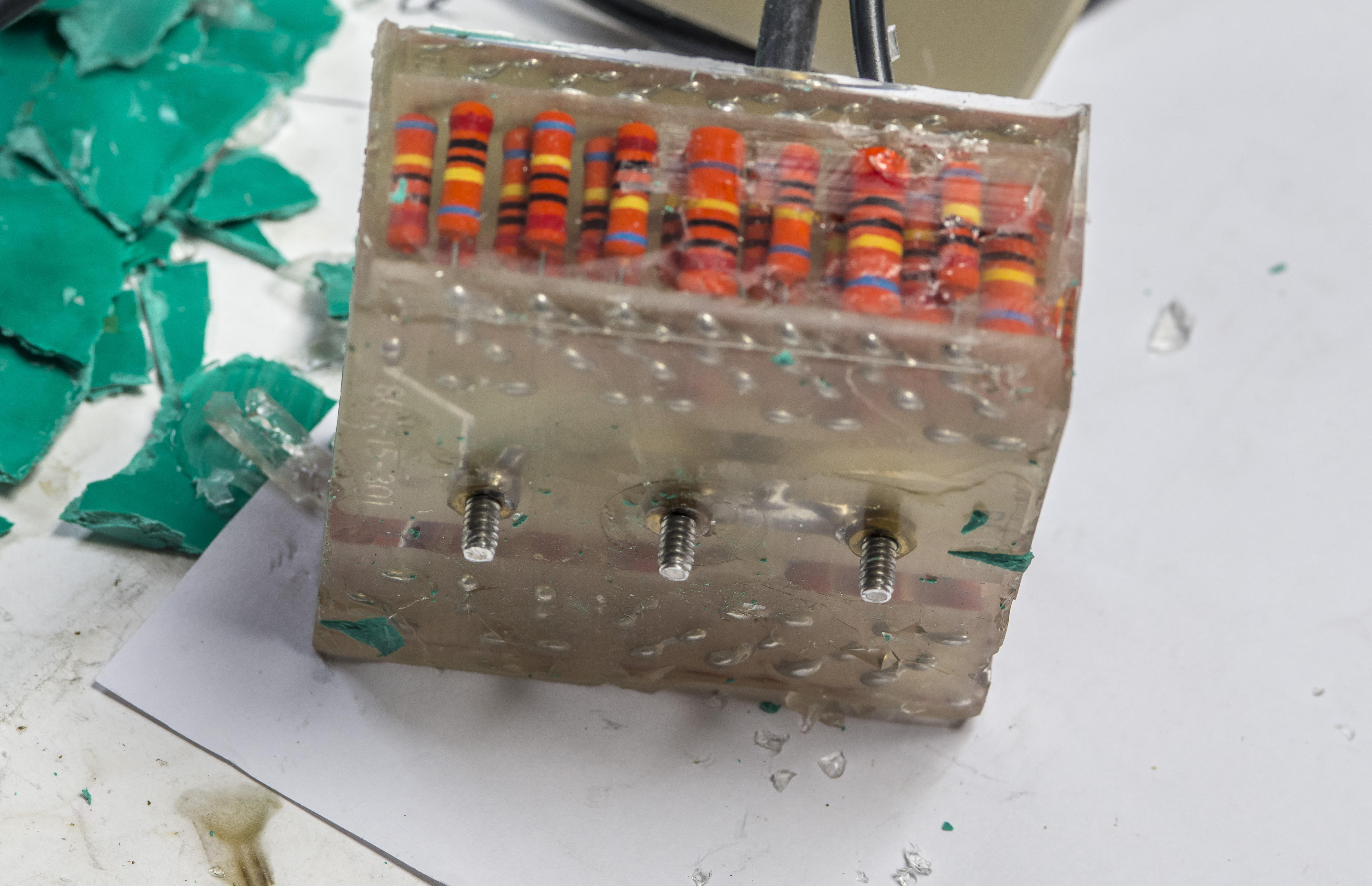
Interface to meter is done with crusty looking nickel plated banana terminals which can be detached. One terminal is output HI and two others are connected to ground LO. Two LO are duplicated to accomodate different meters input jacks spacing that existed at that time.
There is access hole on the top above HI output terminal for multi-turn potentiometer to adjust gain of the probe. Nice attention to details from Fluke designers.
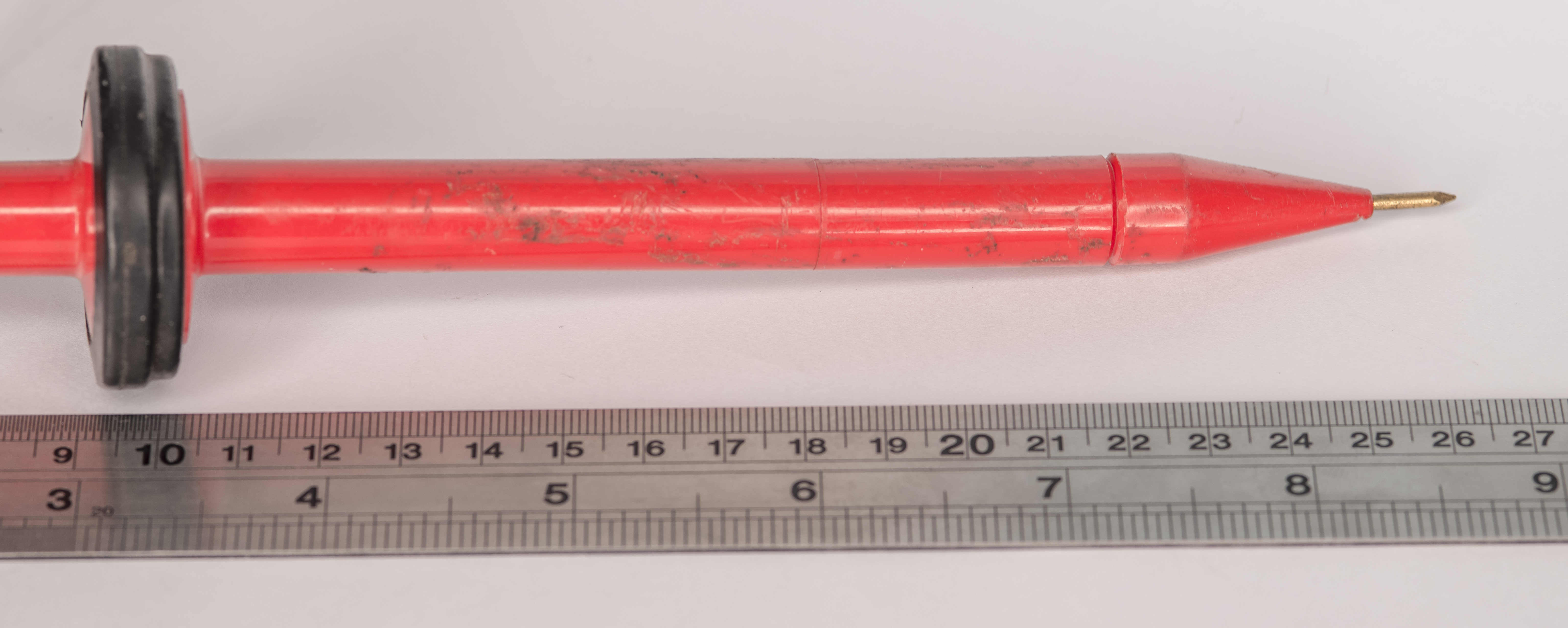
Probe handle itself has hard red plastic shell with arc arrest bulge in the middle to protect the user from high voltage jumping across and ruining your day. Length of the active insulation to the probe tip from the bulged part is about 150 mm which is adequate and well in safe margins for voltage levels up to 15 kV rating. It is important to keep this insulation clean and free of any oils or dirt that could provide conductive path to the user hand from the input signal tip.
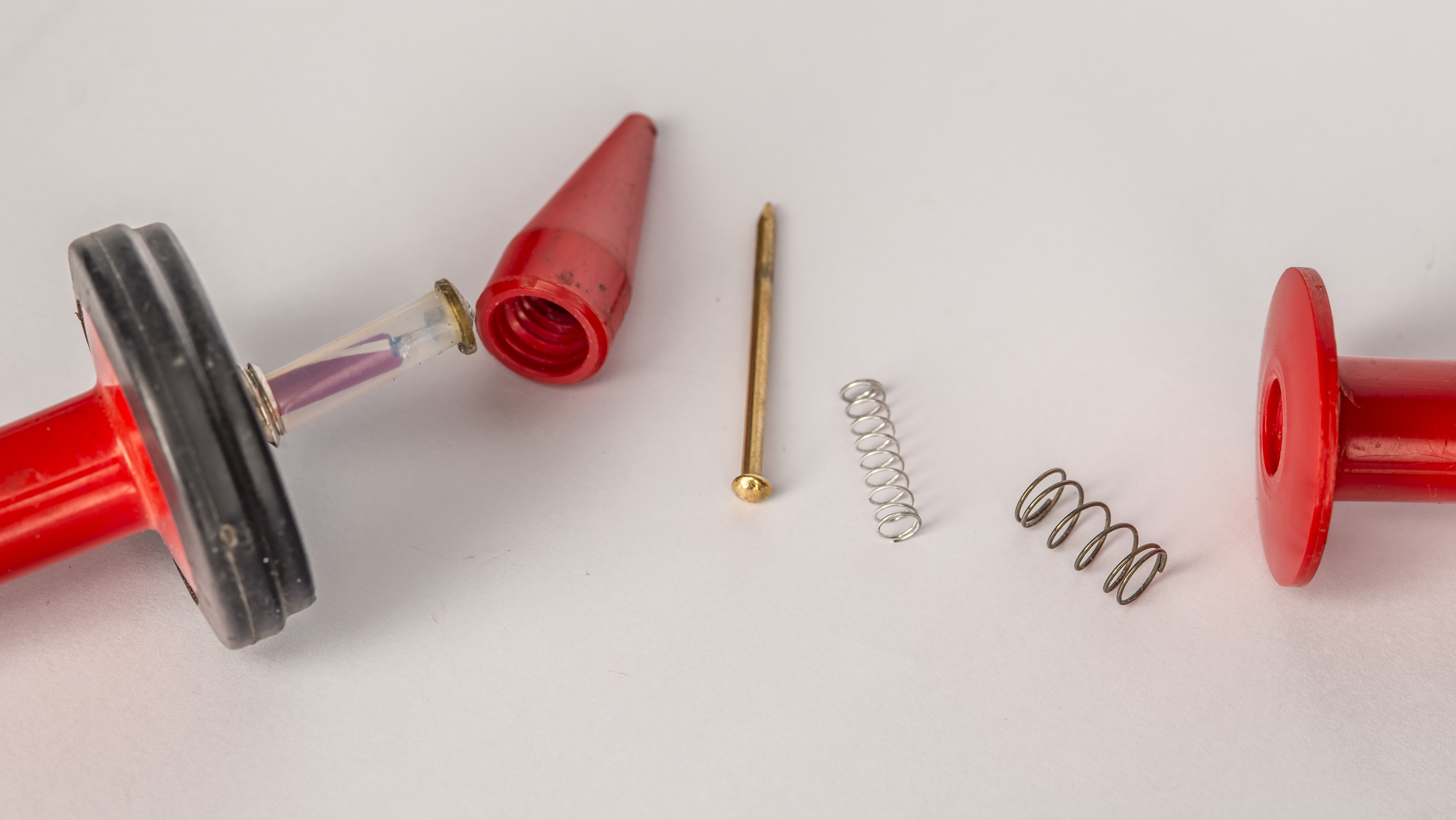
Tip can be removed and we can find there few springs, gold-plated nail and contact in the probe body near the rubber insualted middle section.
Testing
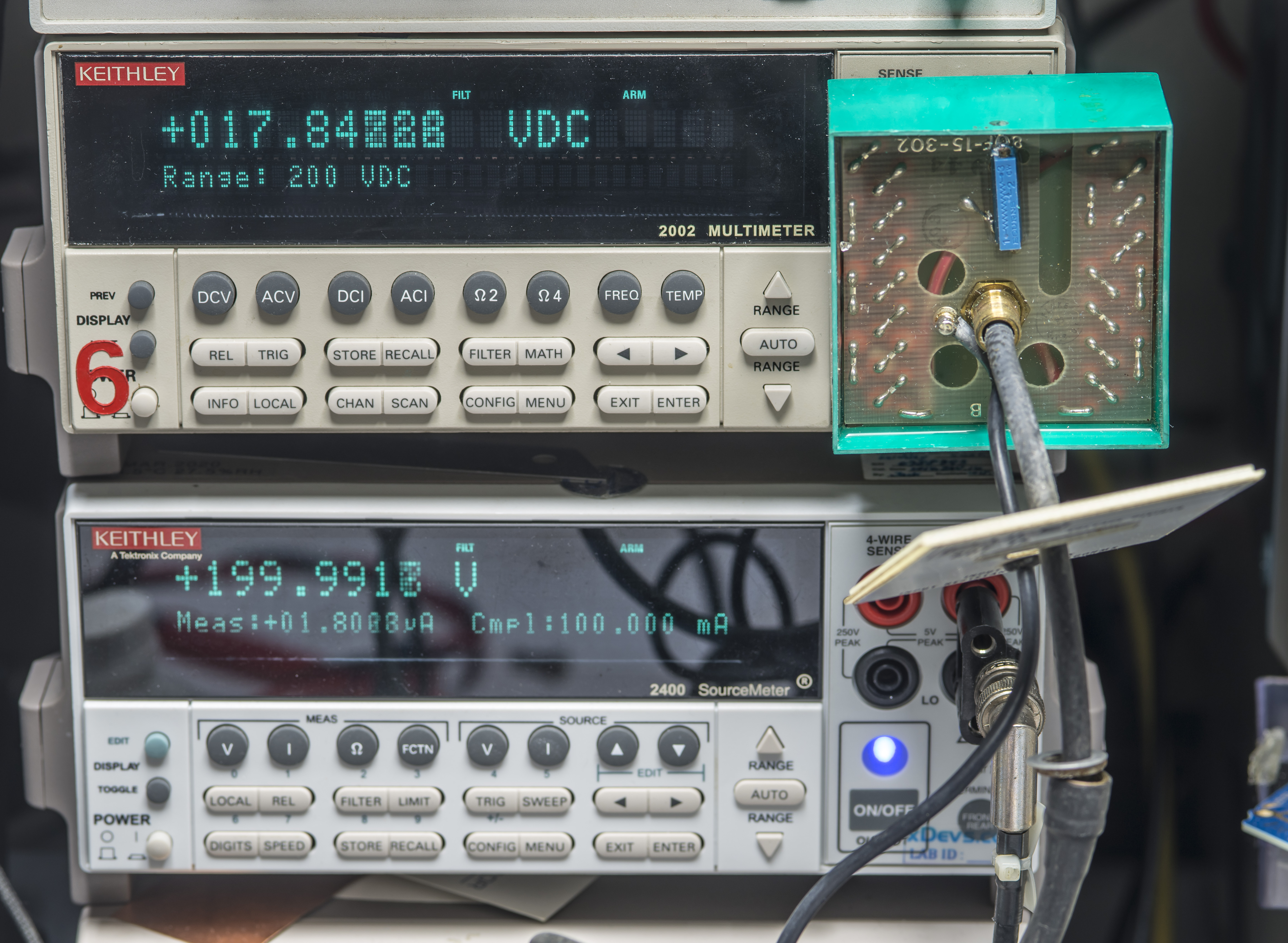
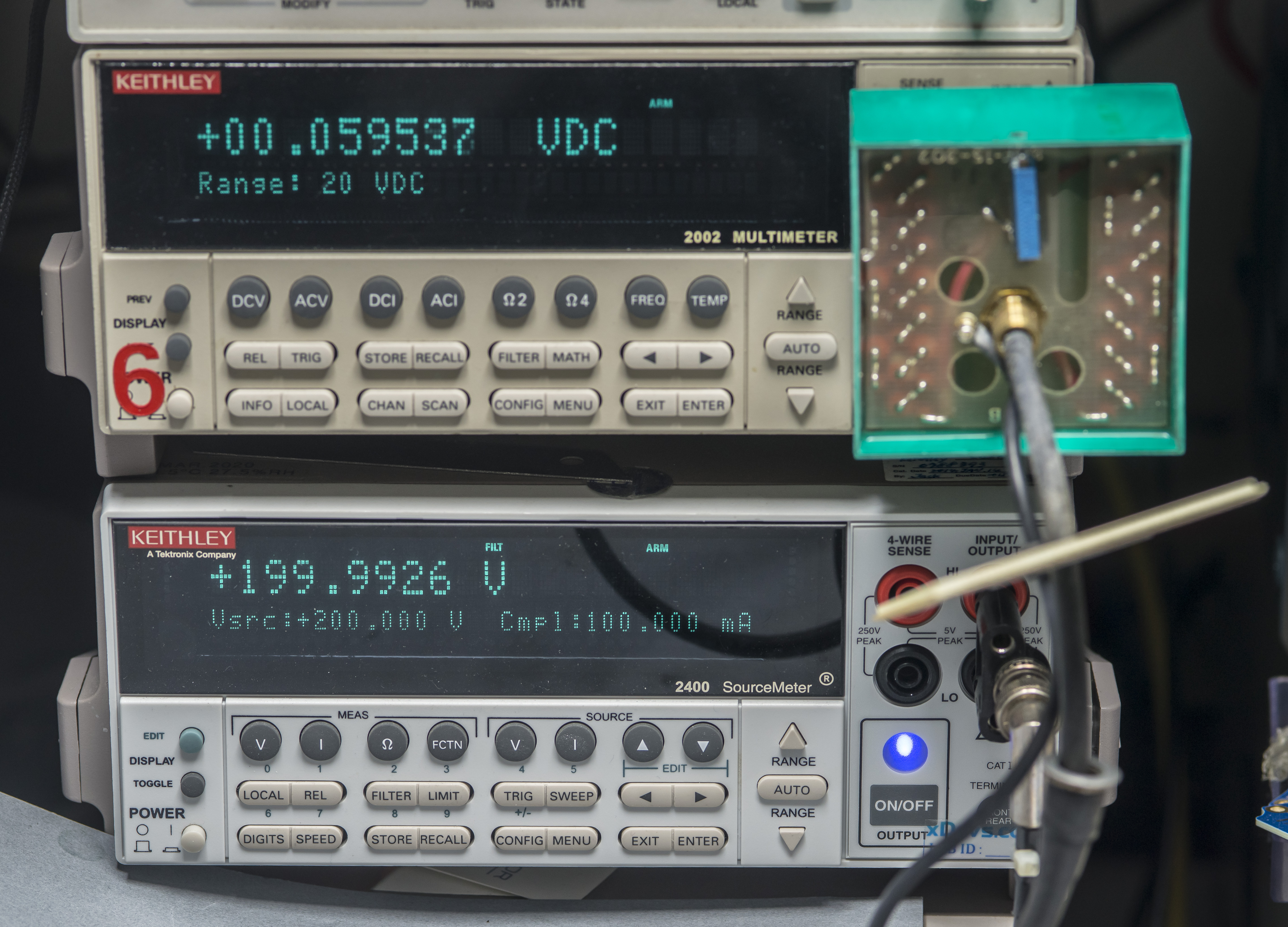
After some quick testing with 200 V signal input the probe was confirmed bad. Voltage was jumping all around the house, sometimes staying at some tens of millivolts, other times going up to 18 V or so. Any movement of cable or fiddling with teal output box was causing readings to go crazy. NOT the expected behaviour of such probe which should just give fixed low voltage output relative to applied input signal. Keithley 2400 used as a source for 200V revealed current draw about 1.8 µA also jumping around a lot.
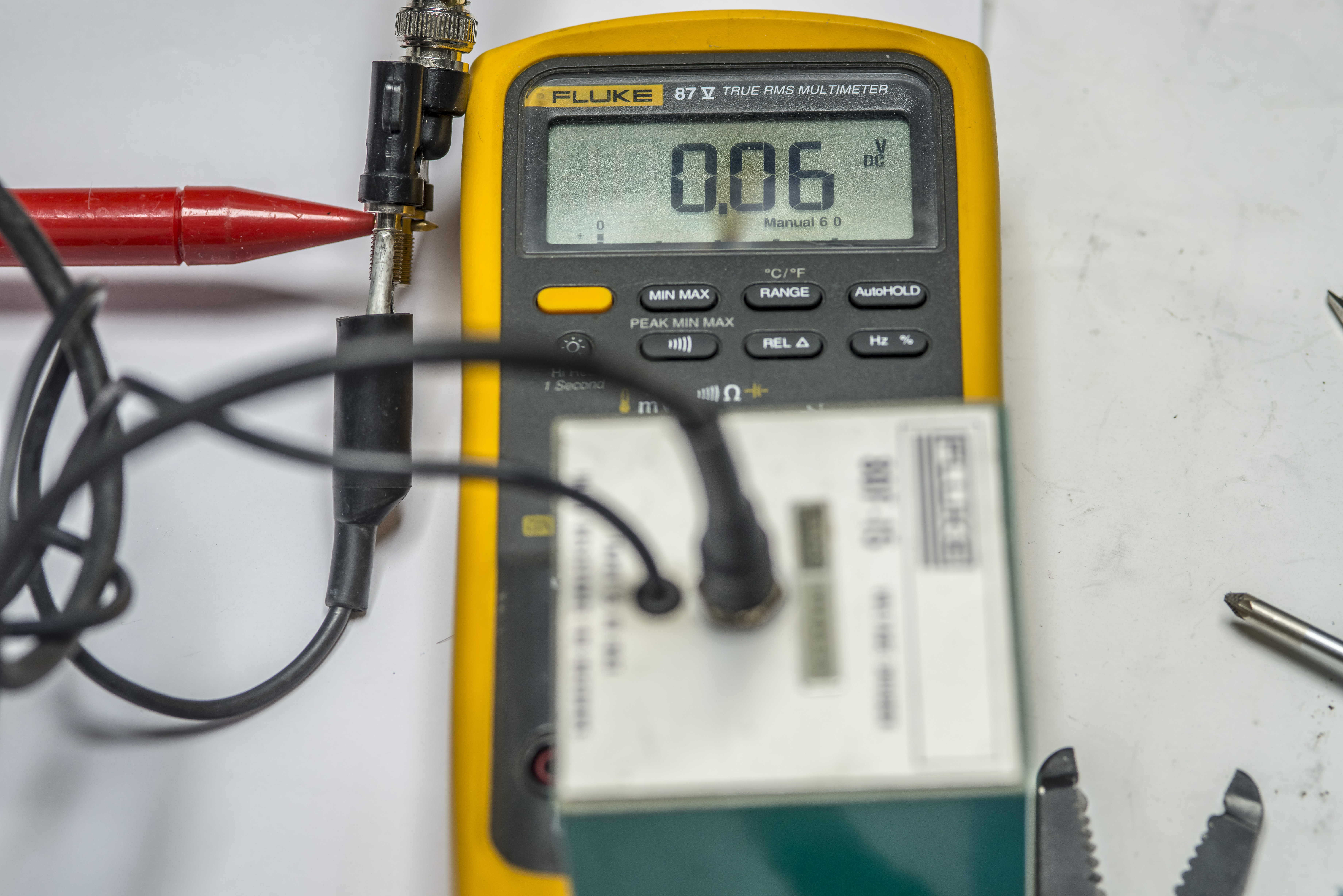
This was also confirmed with using handheld Fluke 87V.
So it looks like bad resistors or cables in the probe. Let’s open it up?
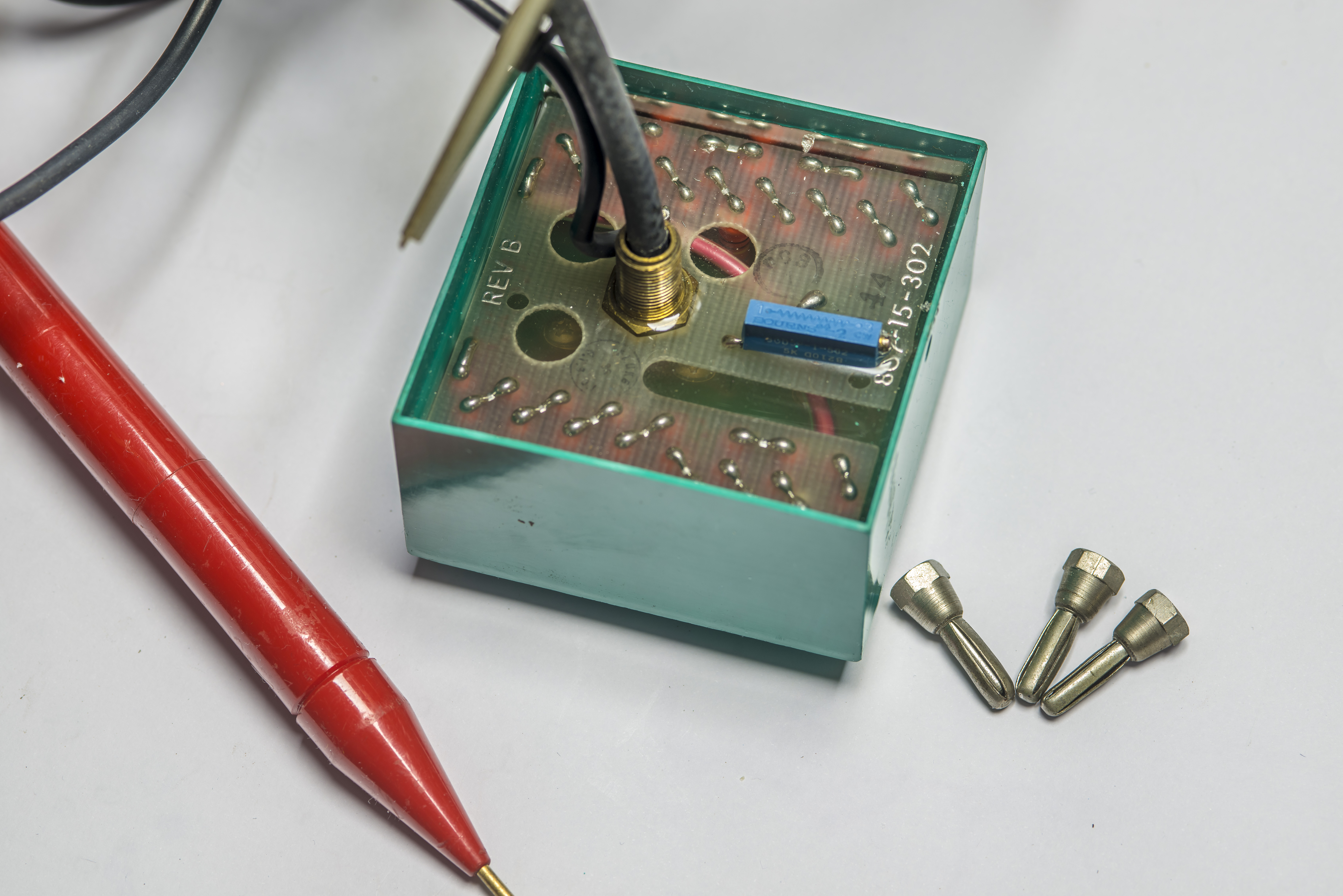
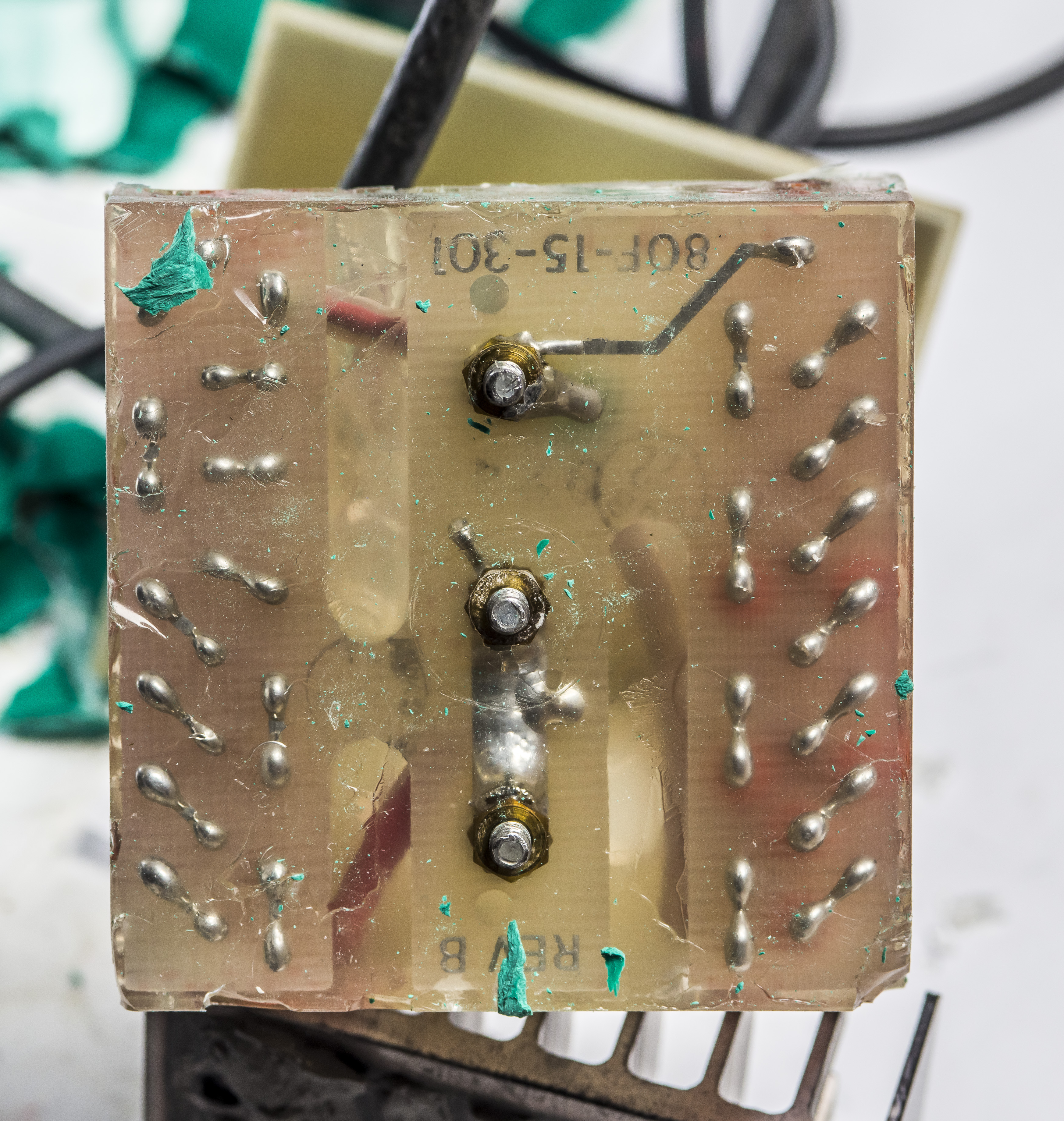
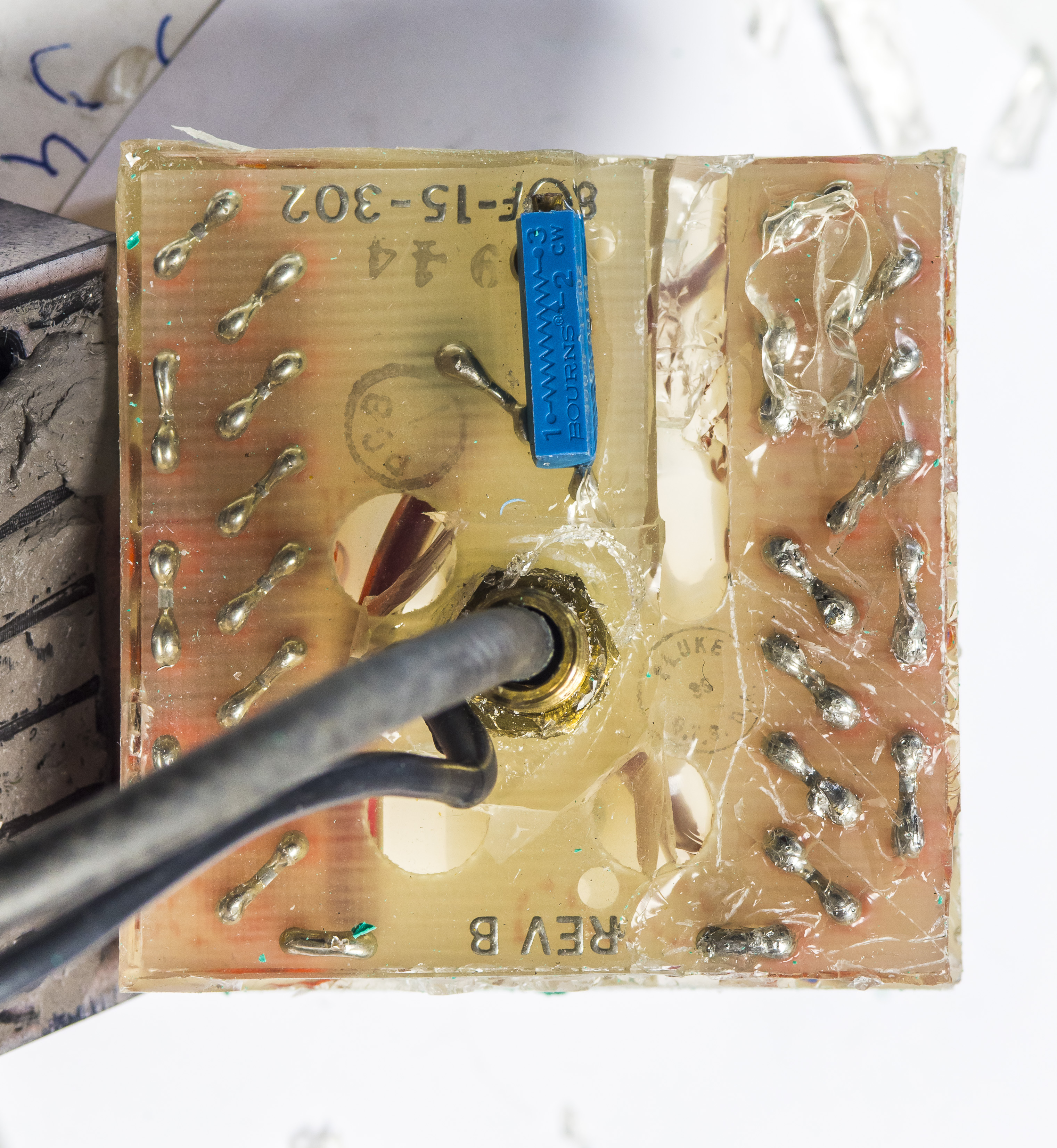
Removing the top nut from HV coax we can pull PCB lid with Fluke label away and see inside of the box. It has two PCBs marked 80F-15-302, stud for soldered in LO cable connection and not much else to it. Whole assembly was inserted into teal box and filled with soft silicone potting compound to avoid any arcover between pins.
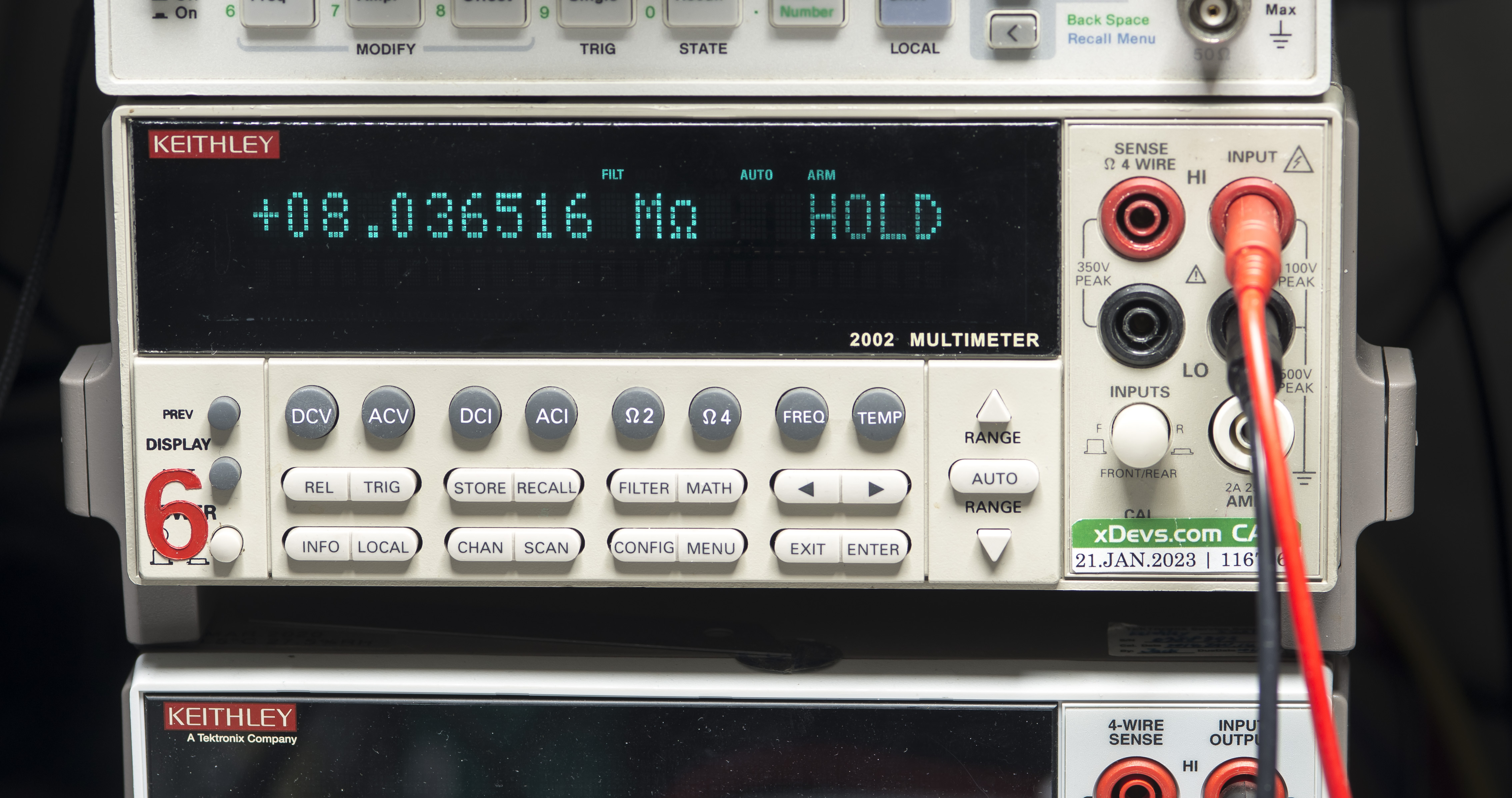
Input resistance of the element inside of the red handle probe was measured at 8.04 MΩ. So remaining 91.96 MΩ must be contained in the potted block. I could count 45 pcs of individual resistors in there which means each of the resistors should be around 2 MΩ.
Soft silicon was pretty easy to poke thru with sharp ProbeMaster probe, so I could confirm that coaxial high voltage cable and ground leads were having good <0.2 Ω connections and didn’t change by physical movement. At this point I was sure one or multiple of those 2 MΩ resistors gone bad.
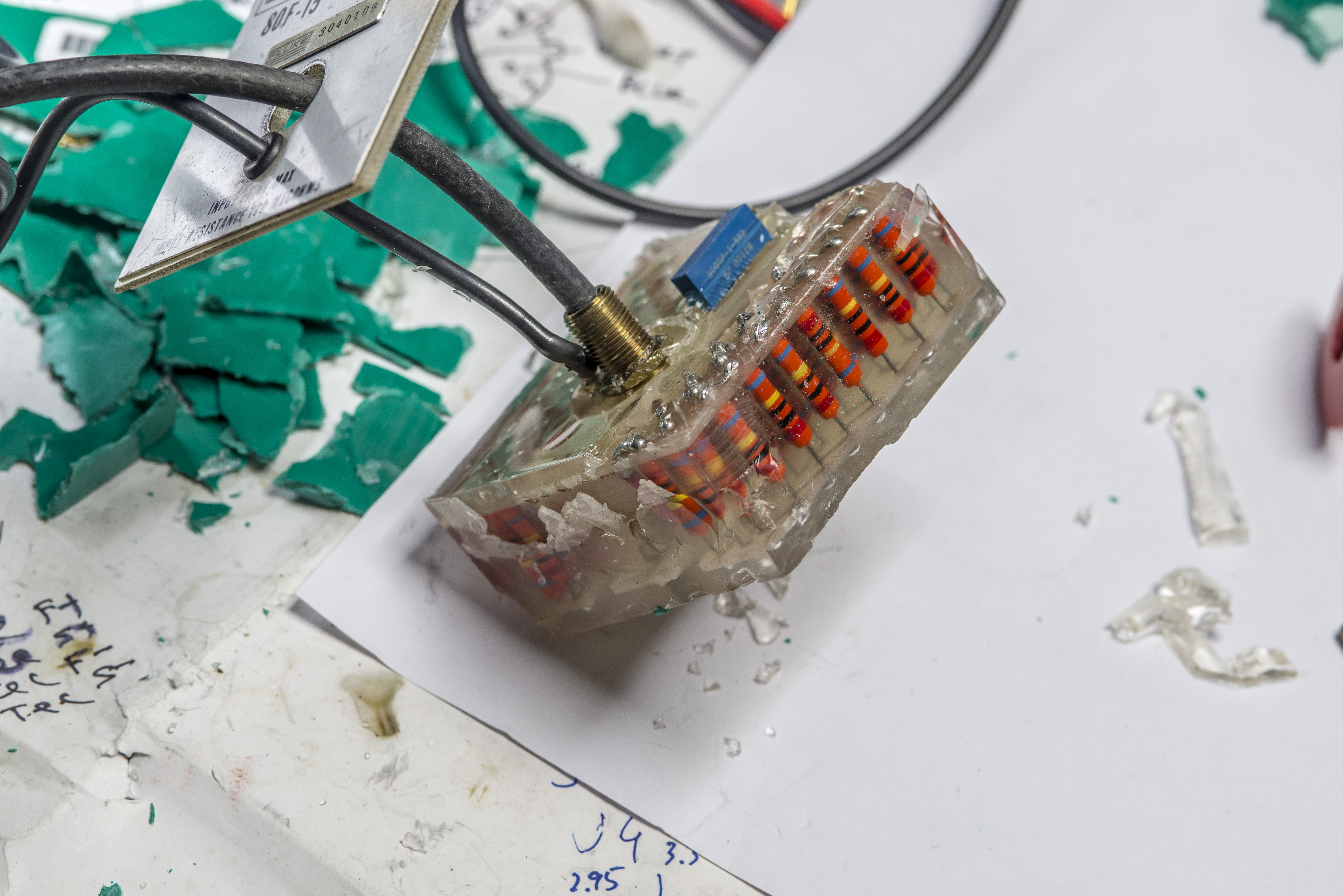
Sadly there was no non-destructive way to take the assembly out of the teal box. We’ll write this down as a sacrifice for knowledge and science.
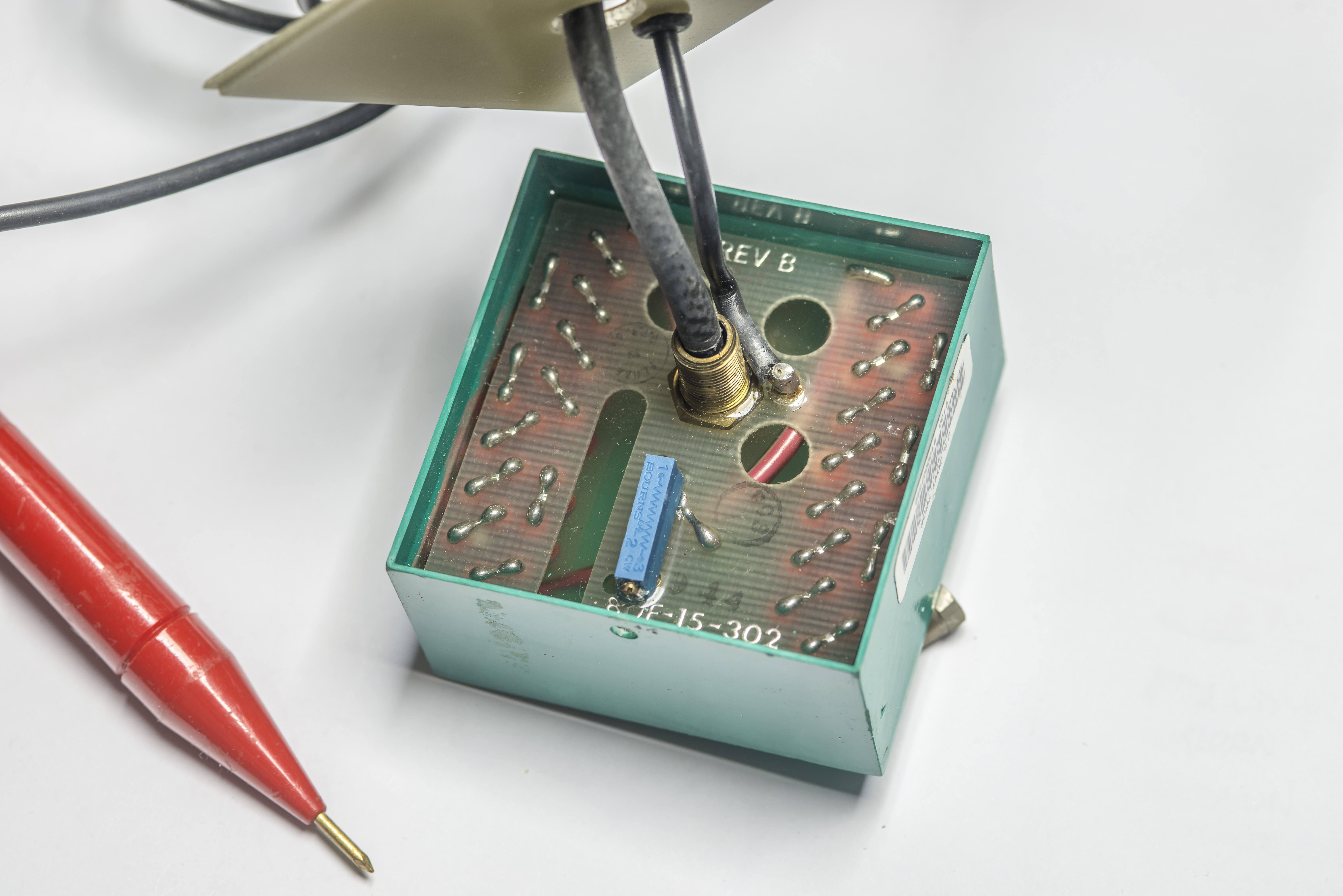
Date code shows it was designed and built around 1999. There are bunch of approval stamps on PCB, perhaps after insulation testing.
PCBs also have cut out slots to further reinforce insulation between two sections of the resistive divider network.
LO connection is indeed revealed as just shorted PCB track between the two.
Overall this article and teardown shows some interesting details about how to design safe high-voltage probe and one of the ways to approach measurements of these levels. I have cut the good and useful input red probe and coaxial and reused it in DIY 90 MΩ resistive network in plastic box to continue with my HV DC voltage measurements.
Discussion is very welcome thru comment section or at our own IRC chat server: xdevs.com (port 6010, channel: #xDevs.com).
Projects like this are born from passion and a desire to share how things work. Education is the foundation of a healthy society - especially important in today's volatile world. xDevs began as a personal project notepad in Kherson, Ukraine back in 2008 and has grown with support of passionate readers just like you. There are no (and never will be) any ads, sponsors or shareholders behind xDevs.com, just a commitment to inspire and help learning. If you are in a position to help others like us, please consider supporting xDevs.com’s home-country Ukraine in its defense of freedom to speak, freedom to live in peace and freedom to choose their way. You can use official site to support Ukraine – United24 or Help99. Every cent counts.
Modified: April 21, 2024, 6:28 p.m.