High resistance measurements are often difficult to perform due to sensitivity for electromagnetic interference. Anybody who tried to measured 100+ MΩ resistance with even high quality DMM such as HP3458A can easily detect those challenges. Even with the ratiometric resistance bridges that can operate with higher voltages this challenge can be still visible. Another issue is air draft movement and charge pickup by exposed terminals, detectable as added noise over the longer durations. This is particularly visible for small hobby labs when measurements are running in background without precise environmental control and HVAC cycling.
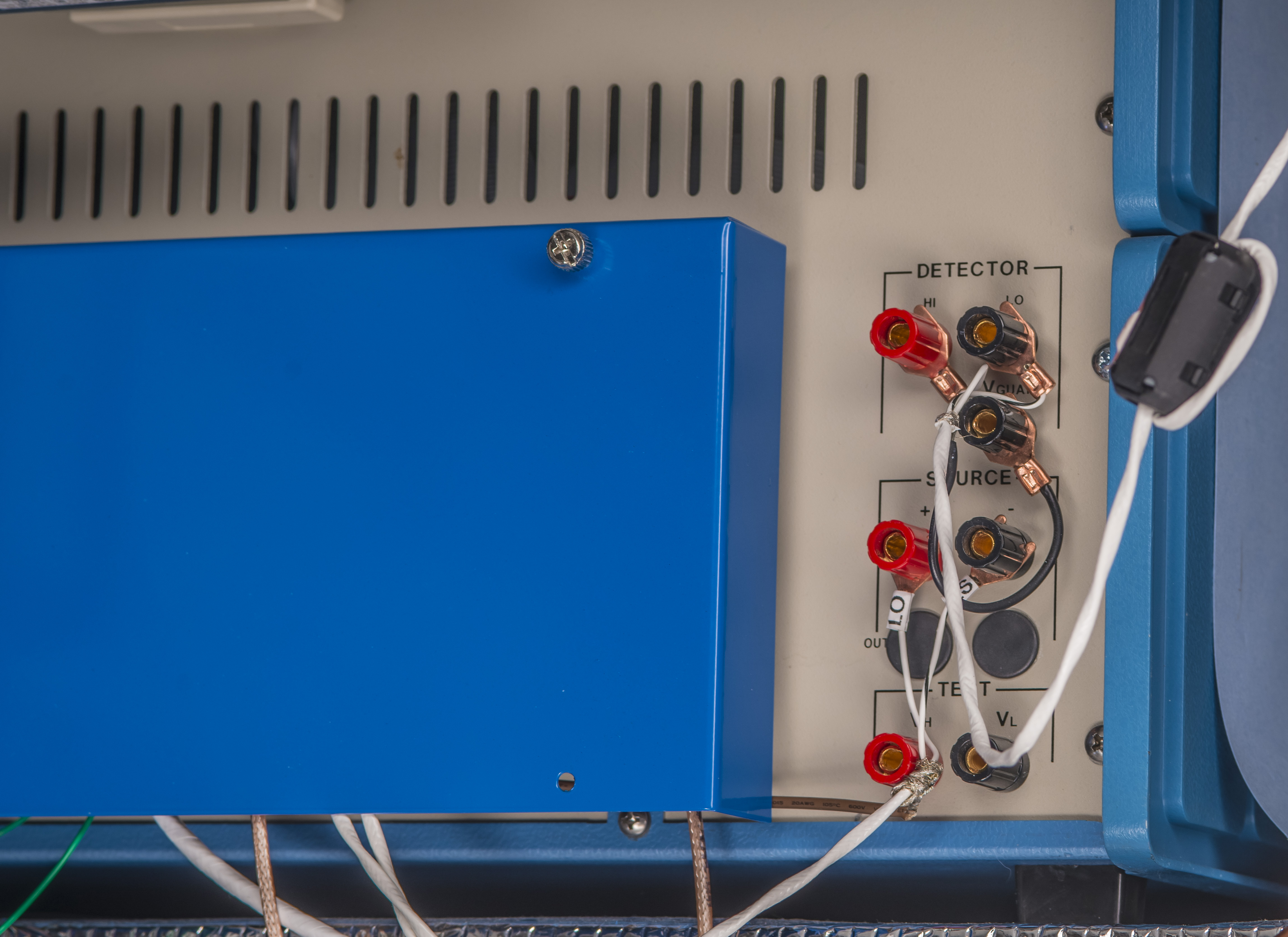
Rogue airflow can cause difference in temperatures at the connectors which will generate parasitic thermal voltages. For daily use instruments such small voltages would not be a big deal but for highly sensitive bridge systems such as MIL 6000B , well capable to resolve 9 digits in resistance measurements such airflow induced voltages can turn into a significant error contributor. To mitigate air draft issue around detector and source connectors at the Measurements International 6000A/B bridge I’ve designed and 3D-printed a simple cover:
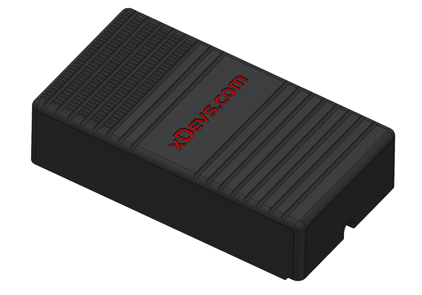
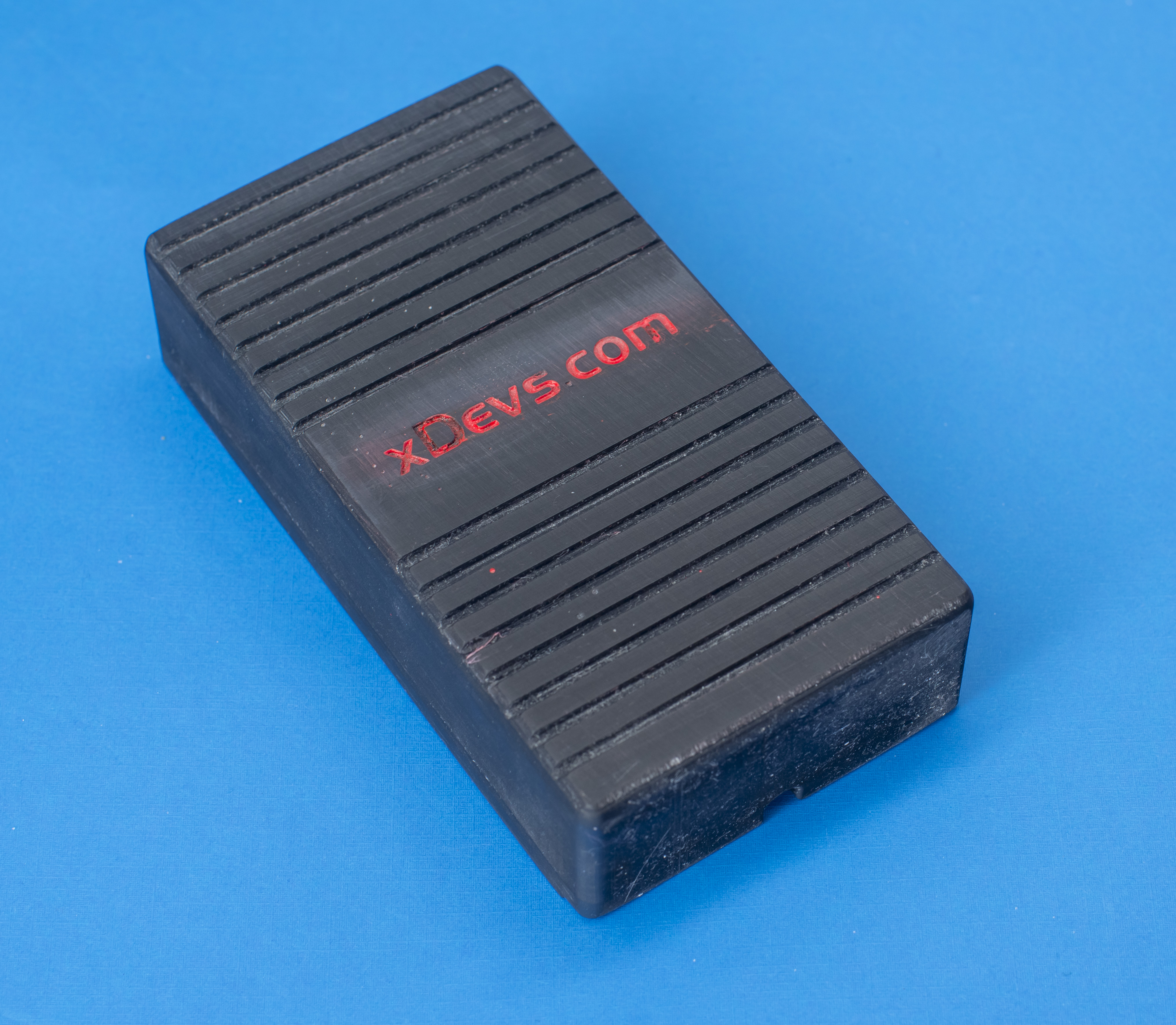
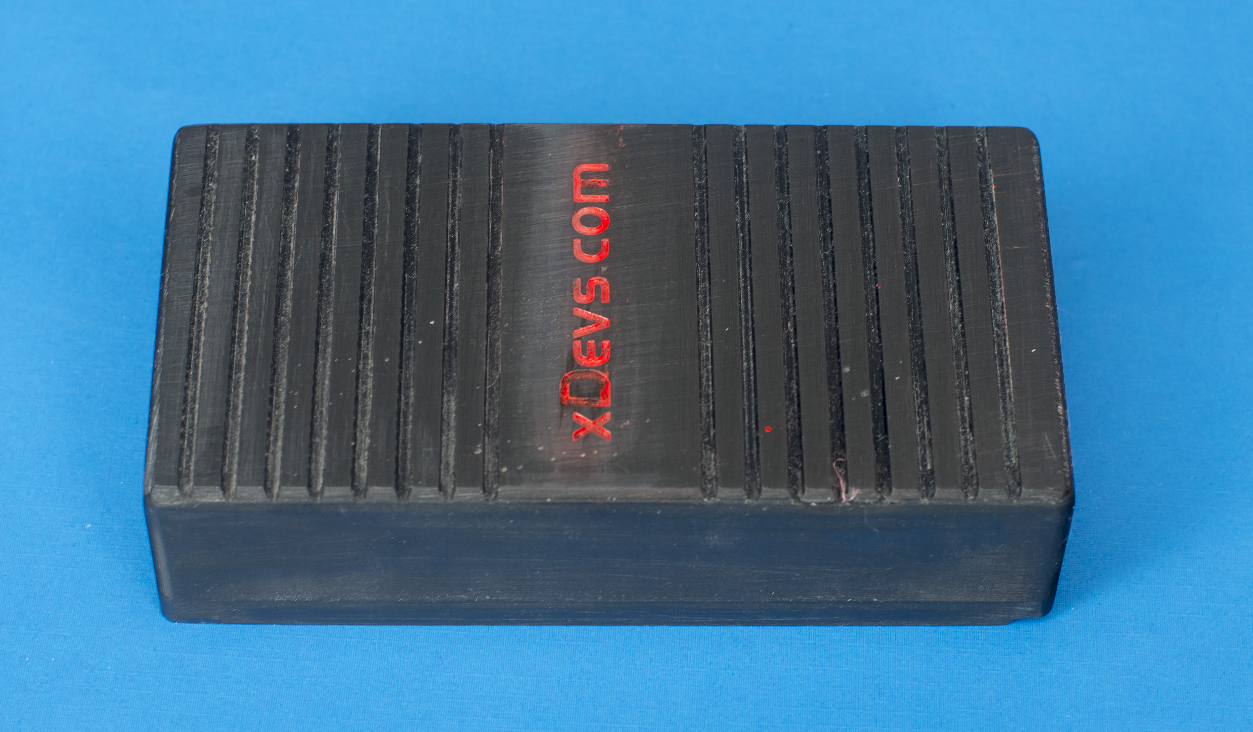
Model dimensions are 70 × 130 × 32 mm. It was printed on Mars 3 Ultra SLA printer with black resin. Total cost of the part was about $5 USD and took just few hours from idea to realization.
STL-format CAD file for 3D printing
After some quick cleaning in 99% IPA and curing with UV lamp model turned out pretty good. I sanded the rough surfaces a bit for better flatness and added some paint into embossed logo letters :)
Cover wall thickness is 5 mm. One could also add some metal foil connected to shield potential for some additional protection, but in my initial experiments that did not improve measurement results so far.
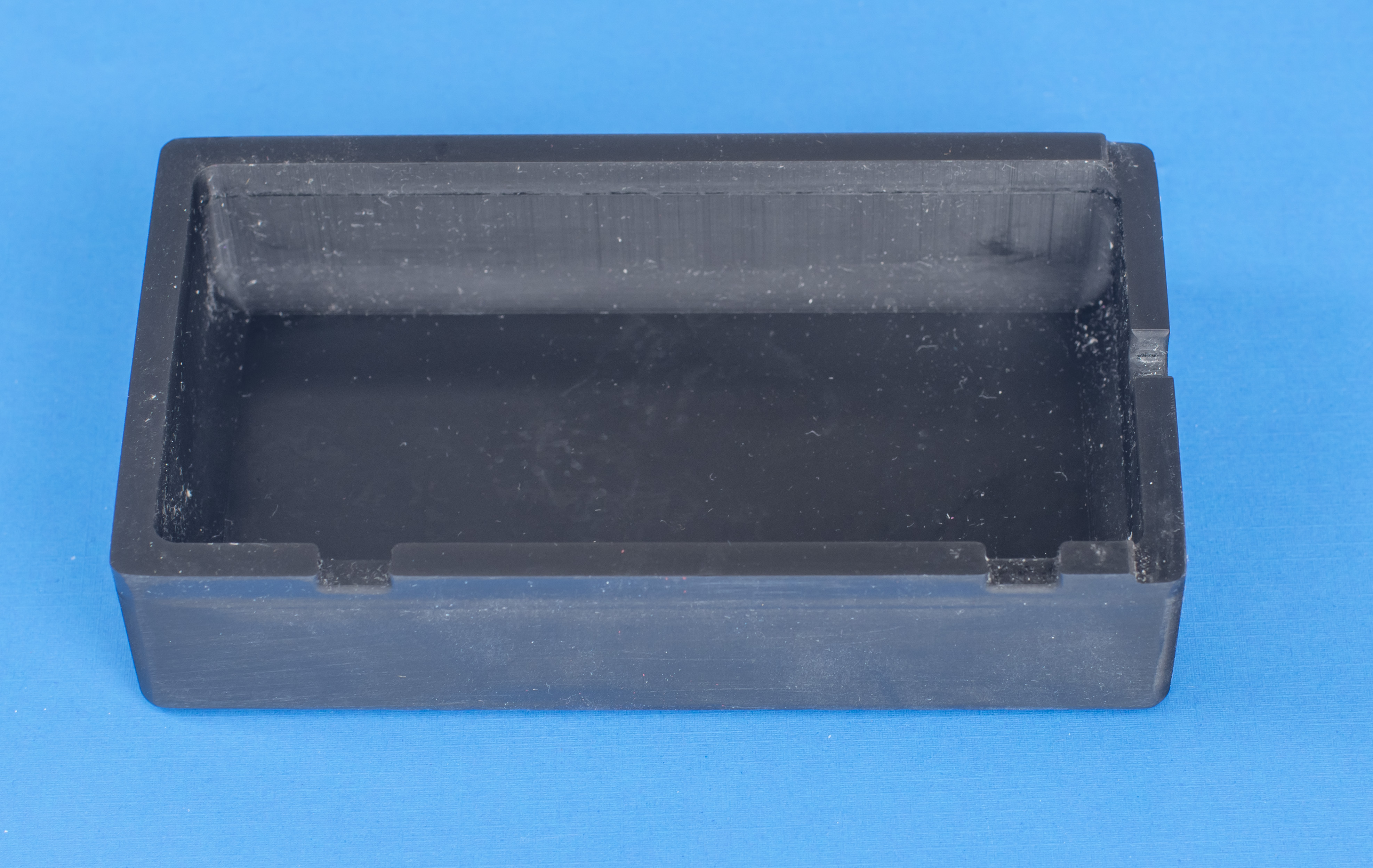
Cover has the cutout for two chassis bolts at the back of MI 6000 bridge and small opening for the cable escape to the external instruments.
And installed on the bridge, with cables running out to HP 3458A voltage detector and Fluke 5720A voltage source.
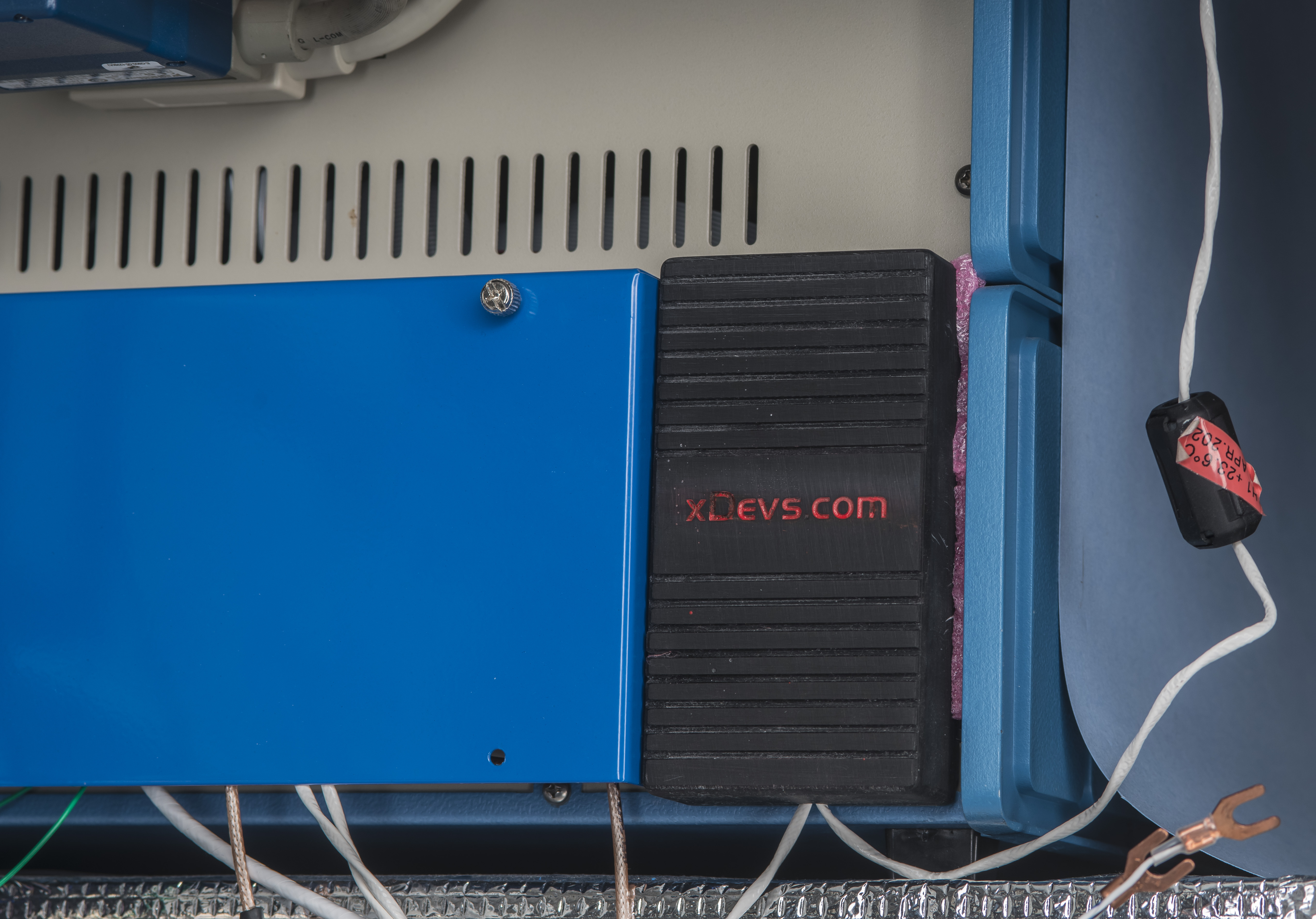
Cover is installed in place with a bit of ESD-safe foam jammed between bridge edge wall and cover. That provides plenty of friction force to keep cover well secured at the back with no significant gap from the chassis. Alternative option would be to add few small pieces of double-tape around cover perimeter and stick it on the bridge.
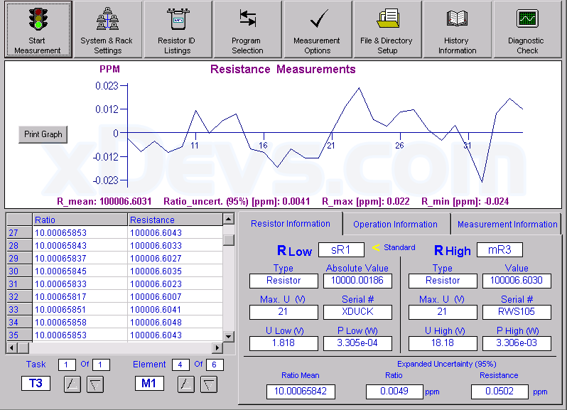
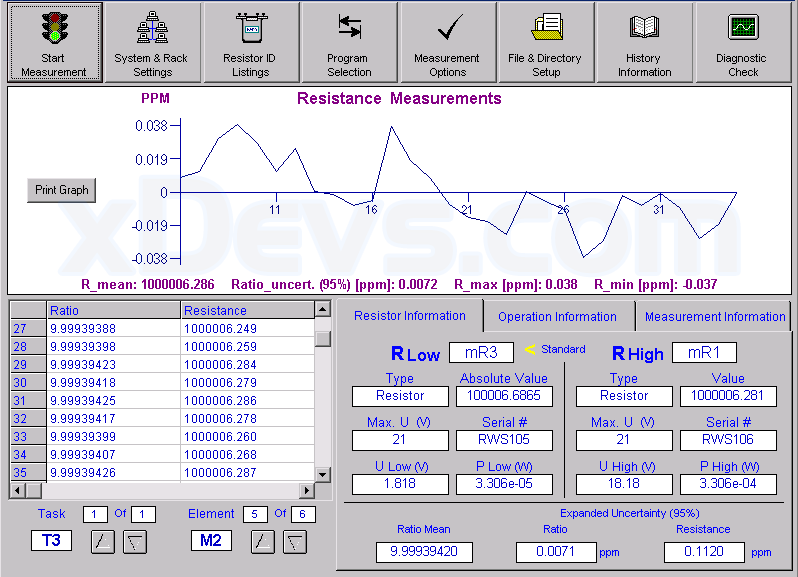
Practical result of the measurement during comparison between 10 kΩ ESI SR104 reference standard and 100 kΩ and 1 MΩ resistance standards at +23.0 °C. Transfer to 100 kΩ produced ratio mean 10.00065842 with ratio uncertainty 4.9 nΩ/Ω and relative resistance ratio 0.05 µΩ/Ω. Second test to 1 MΩ standard resulted with ratio mean 9.99939420, ratio uncertainty 7.1 nΩ/Ω and relative resistance ratio 0.112 µΩ/Ω. By using known resistance 10000.0017 Ω of the reference standard the output of higher resistance elements can be calculated with simple multiplication from ratio results. Stability and noise performance of system like MI 6000 is very impressive and impossible to match by any kind of DMM.
Hopefully this short post provide a clear demonstration on easy and cheap option way to make one off parts to help metrology applications.
Stay tuned and let us know your feedback on this post! Discussion about this and related stuff is also welcome in comment section or at our own IRC chat server: xdevs.com (port six-zero-ten-zero, channel: #xDevs.com) or via e-mail.
Projects like this are born from passion and a desire to share how things work. Education is the foundation of a healthy society - especially important in today's volatile world. xDevs began as a personal project notepad in Kherson, Ukraine back in 2008 and has grown with support of passionate readers just like you. There are no (and never will be) any ads, sponsors or shareholders behind xDevs.com, just a commitment to inspire and help learning. If you are in a position to help others like us, please consider supporting xDevs.com’s home-country Ukraine in its defense of freedom to speak, freedom to live in peace and freedom to choose their way. You can use official site to support Ukraine – United24 or Help99. Every cent counts.
Modified: Jan. 23, 2024, 4:34 a.m.