First week of February is another time for golden resistors. Yet another resistor network from Vishay Precision Group in 8-pin TO-99 hermetic packaging. It is build using set of BMF elements, more commonly known by their famous VHP resistors. But unlike VHP resistors these networks are made to custom order only, with customer specified values and specification requirements.
Vishay Precision Group 1413 Datasheet
VPG Presentation about resistor networks
This resistor network belong to 1413 series of the ceramic hermetical network packages, with 8 pins. This package can fit up to 9 V5×5 resistor chips or up to 3 V15×5 chips, with total maximum power rating 0.4 W.
All of these chips built with chips glued to the metal case and wirebonded to isolated pins. There are many more package variants also available from VPG for custom designs with other series as well, both with larger and smaller cans.
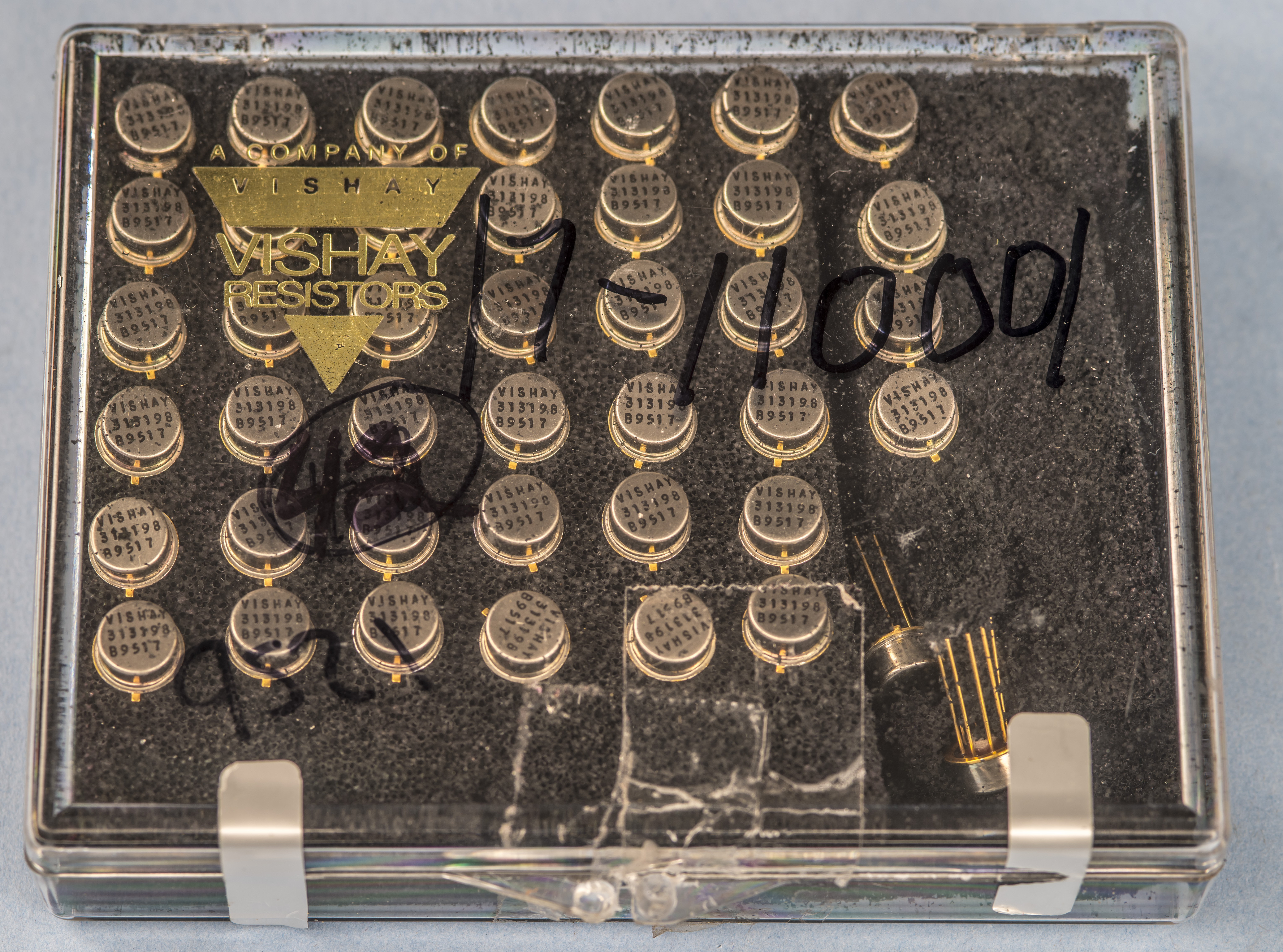
Resistors were aquired from secondary market as NOS kit. Black conductive foam is also falling apart leaving lot of mess.
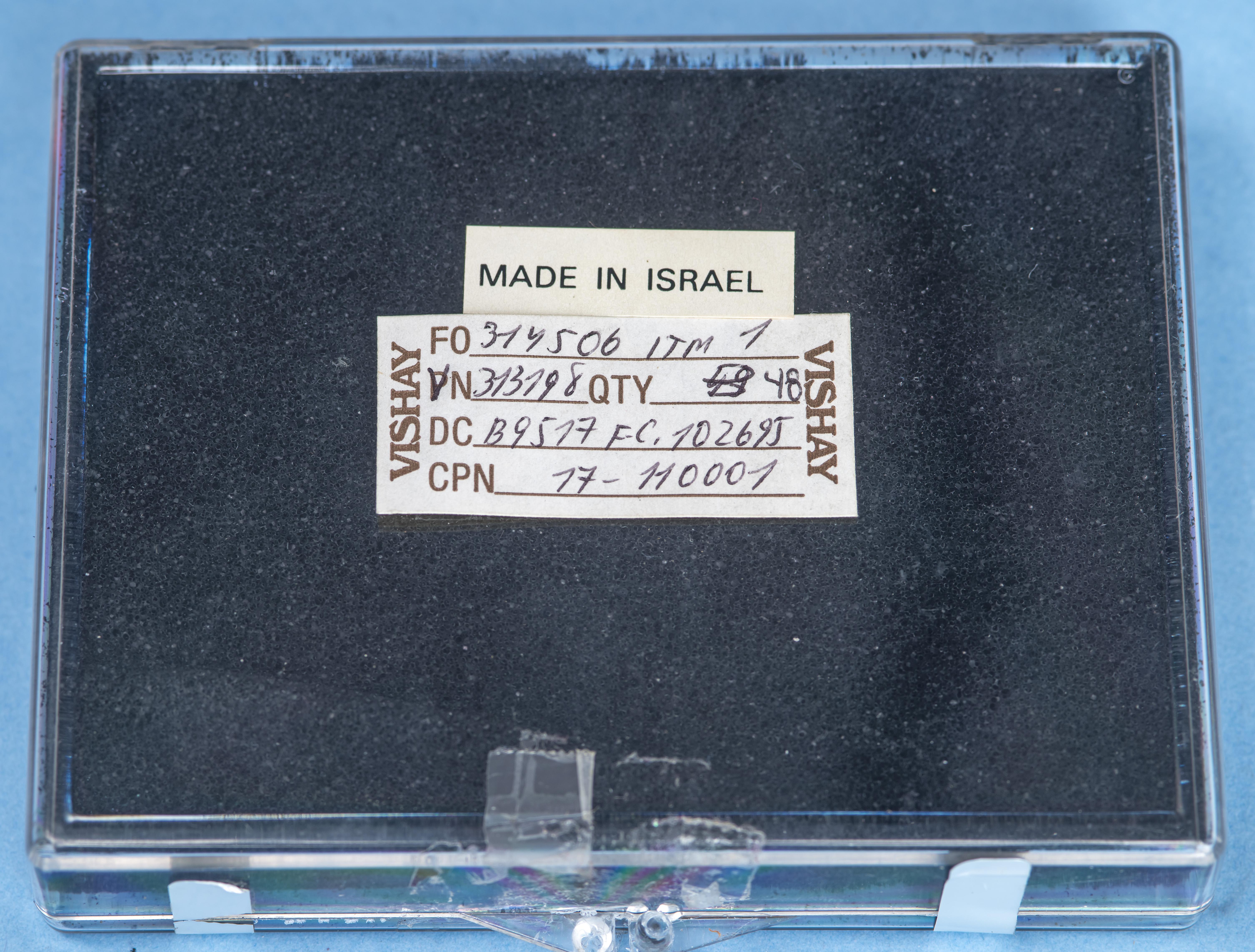
Label shows Vishay custom part-number and qty 49 or 48 pcs, and bunch of other codes for internal reasons unknown to us. But we got only 42 pcs for now here.
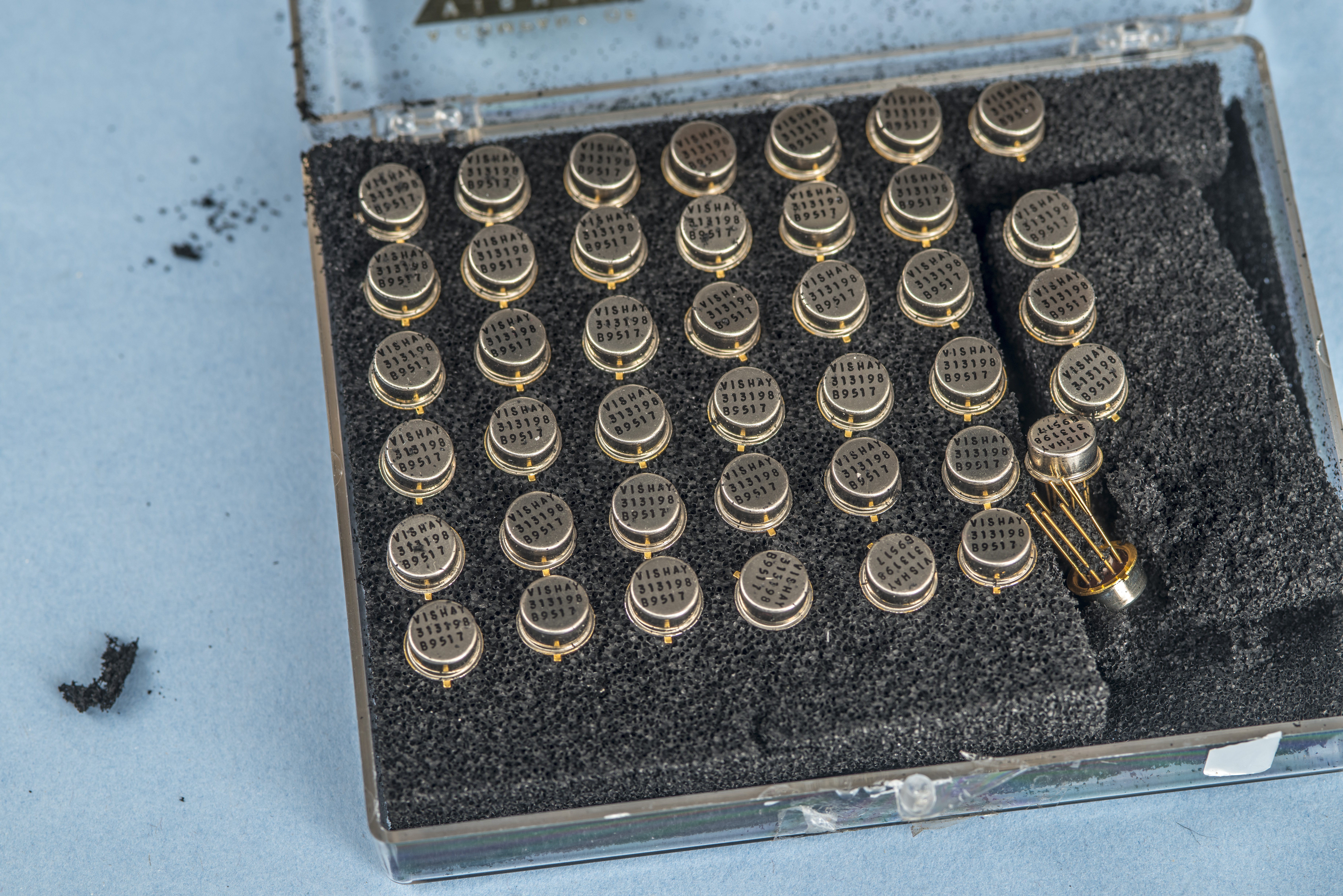
Opening box reveals pretty golden cans that look well aged. On the top we are greeted by inked VISHAY logo and part-number, as well as manufacturing date code 17 week 1995. All chips have same marking, so should be identical in internal configuration internally.
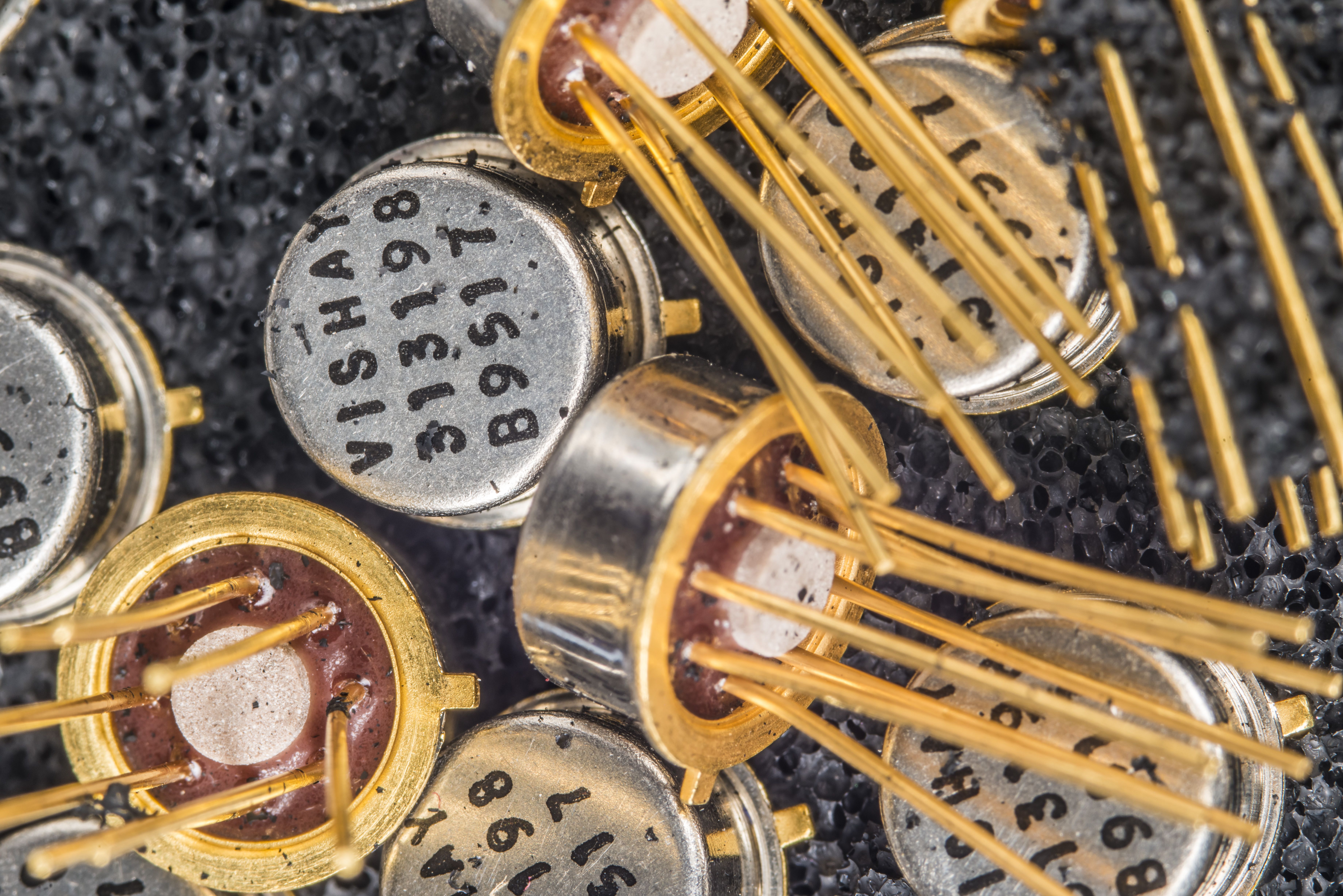
Tear down of hermetic package like this is very easy. Just a little bit of metal cutting and can is open, with all connections and gold wirebonds intact. I’ve sacrificed one network to get a better look at internal construction. Top metal can made out of Nickel and bottom base with pins is gold-plated Kovar alloy to ensure good uniform seal with glass insulator around pins. Once resistor elements attached to the base and wire bonded factory put a top cap on and welds the seal hermetically. There is no oil inside of these resistor networks.
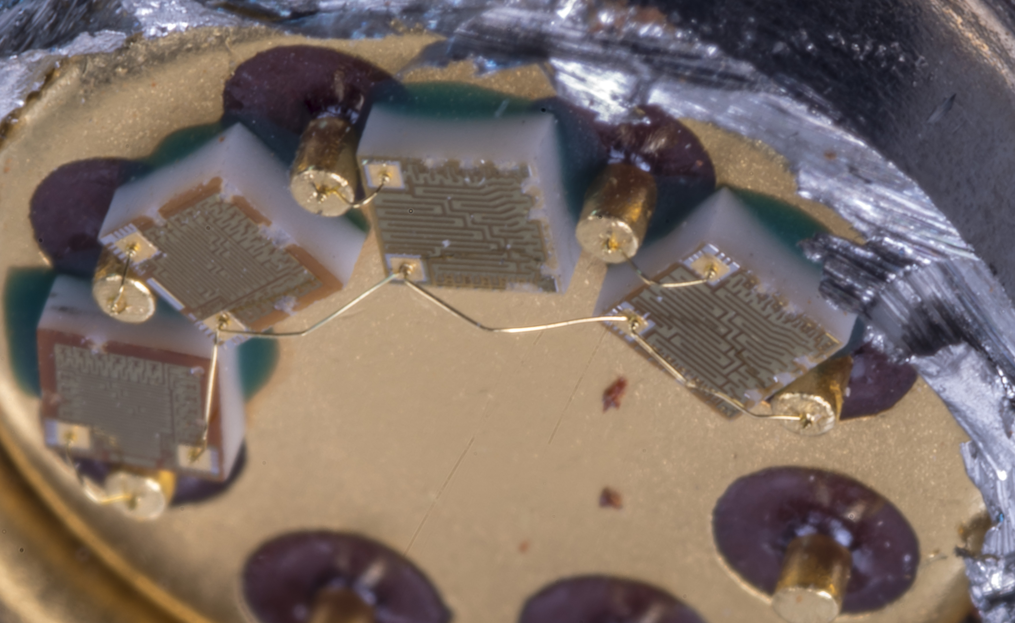
Configuration is pretty simple with pin 1 used as common connection point for all four chips and pins 2,3,4,5 for remaining connection to each resistor chip.
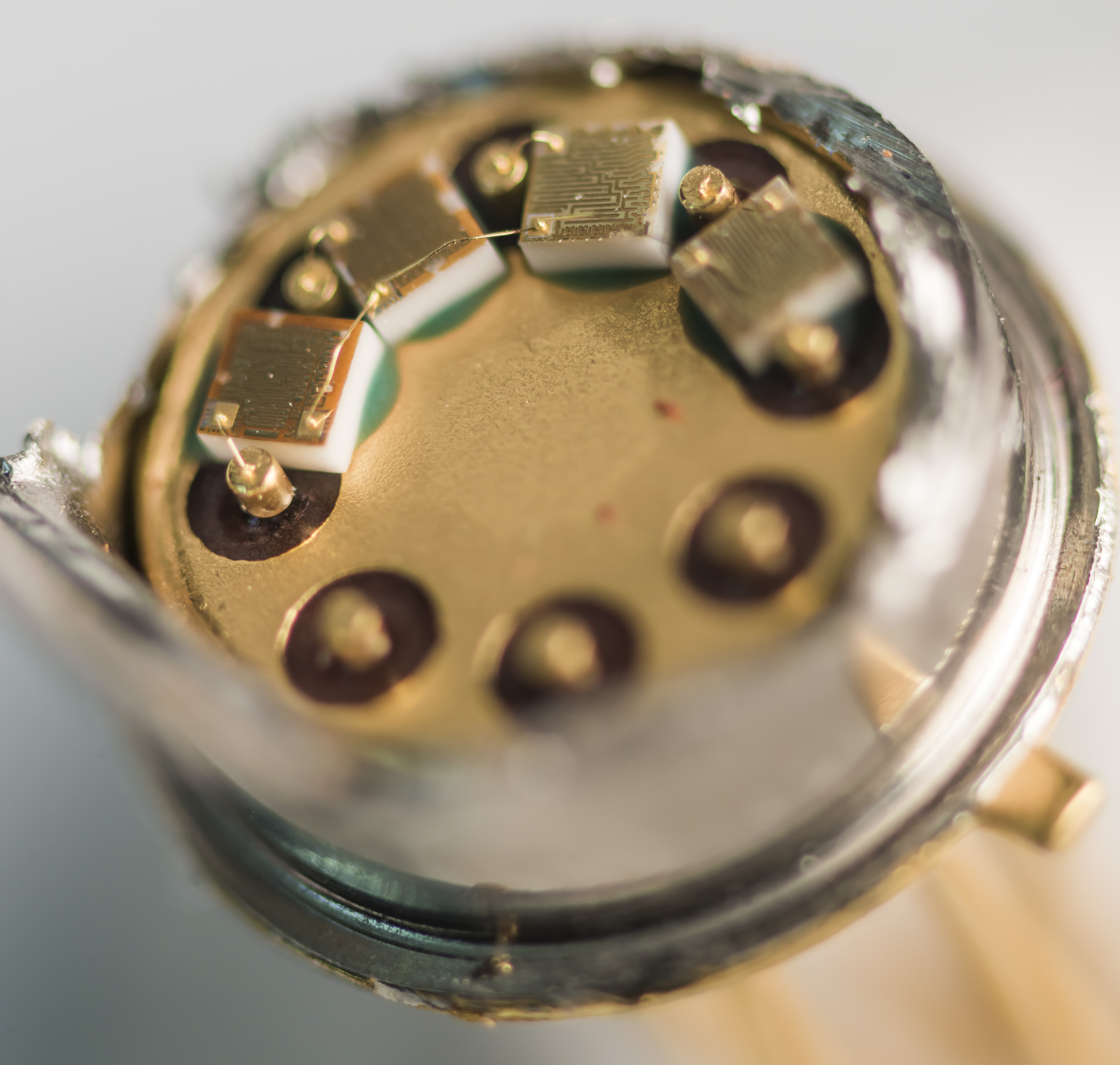
Chips have quite thick ceramic base with some green epoxy to fix them on the can.
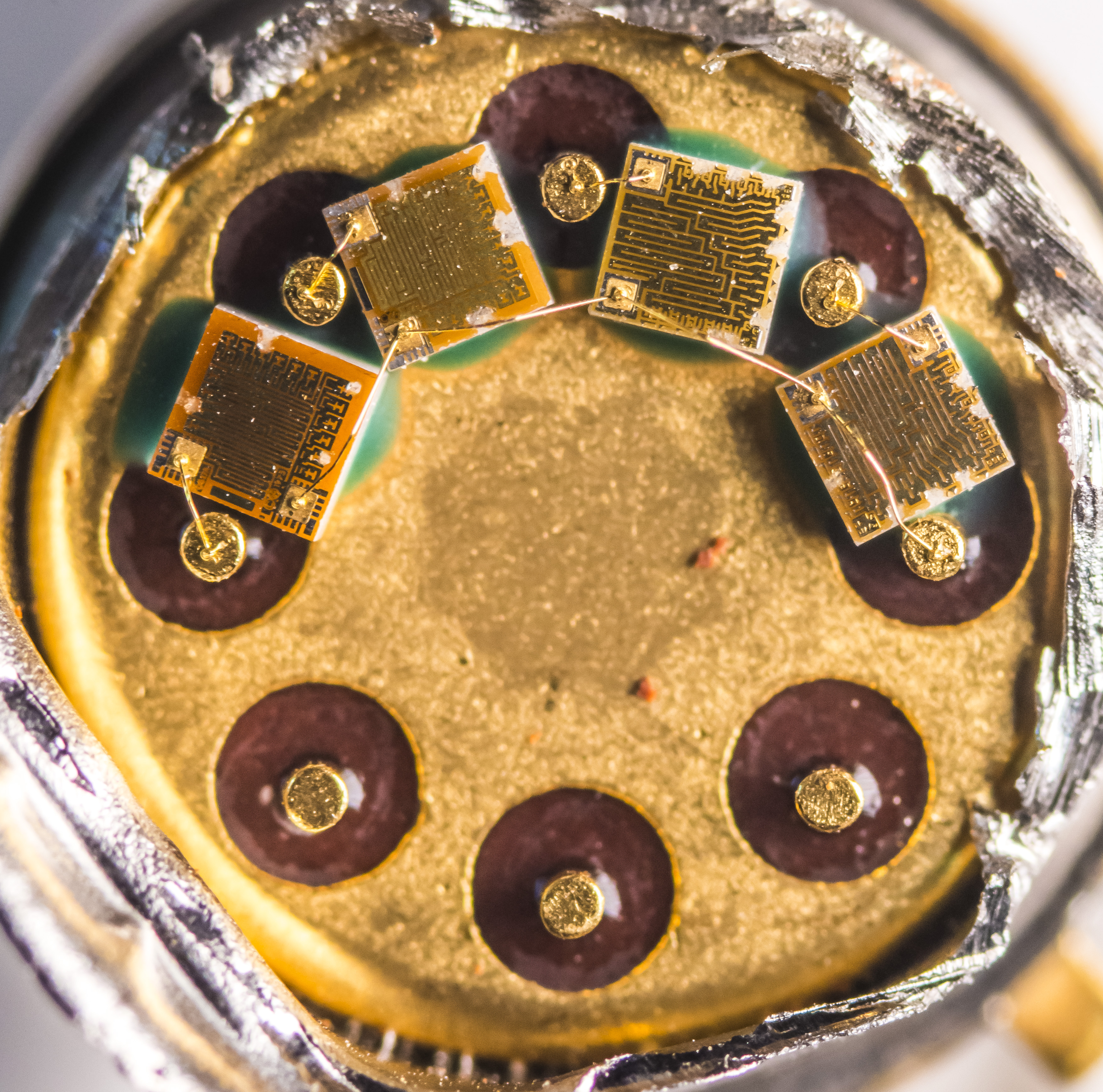
This network is using four V5×5 resistor chips. Each chip is bonded to terminal contact pad by thin gold wire and glued to the conductive carrier surface with green epoxy. Metal can is isolated from any of the 8 available terminals. We can study datasheet for these resistive chip elements for more details.
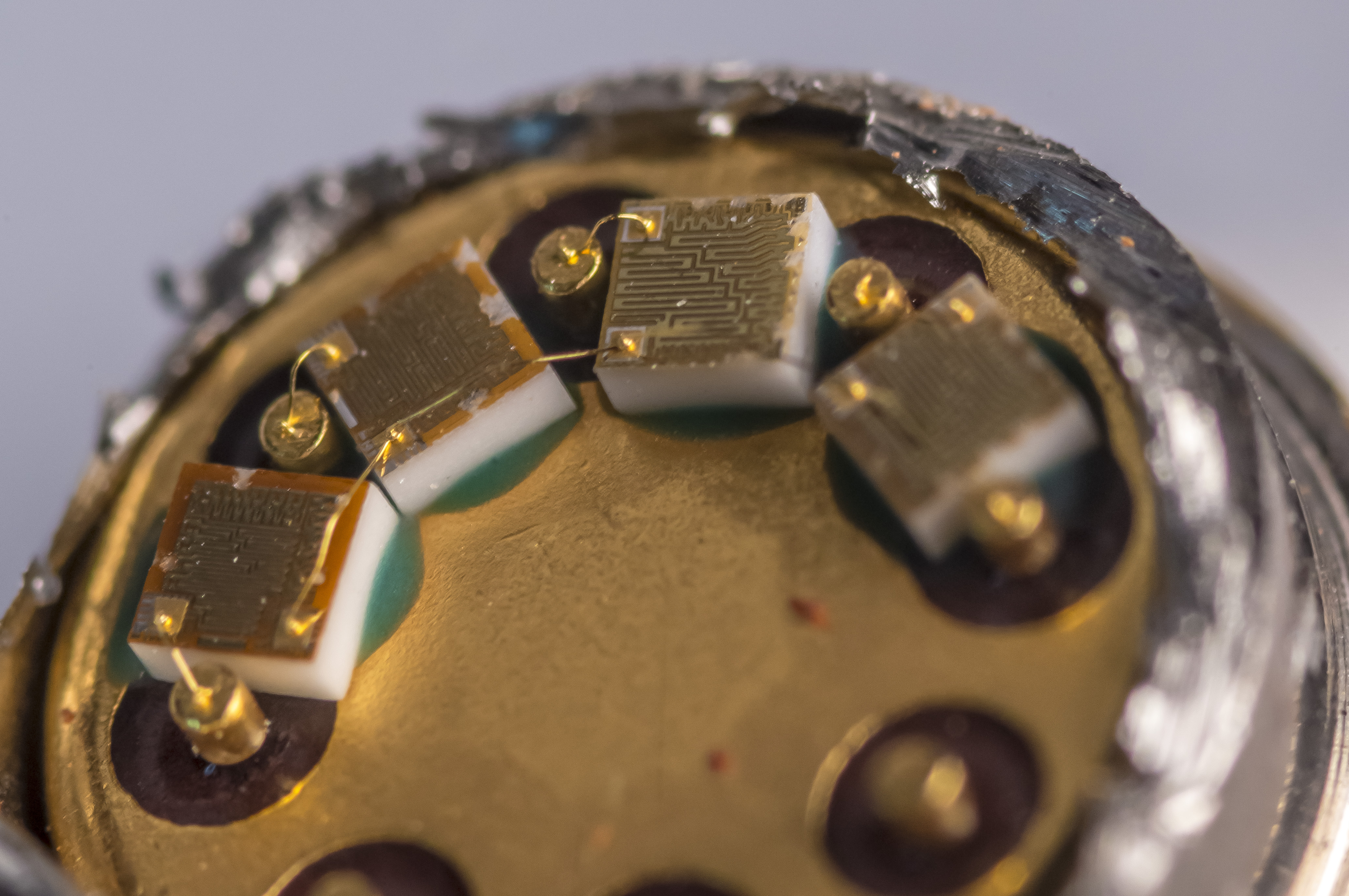
It is also very easy to see the marks from laser trimming procedure used to adjust final value of the resistor chip to the specification.
Vishay Precision Group V5×5P element datasheet
These chips are essentially network of foil resistors with possibility to short sections to obtain necessary ohmic value between two gold plated pad terminations. Trims are cut mechanically or with laser, increasing resistance of the chip. By having large number of trim points resistance value of each chip can be set in “digital” manner during fabrication.
Initial measurements of one of these 1413 networks with Keithley 2002 DMM revealed final values and circuit connections shown below:
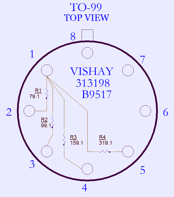
This setup allows many interesting ideas. Like building some trim-networks for LTZ/ADR1000 references or combining multiple networks together to make some funky programmable resistance output device. It would be more flexible with chips isolated connections, but even current configuration can be quite powerful to generate some useful resistance values in range from 31.1 Ω (all resistors parallel) to 478.2 Ω (largest resistors in series).
| Example configuration | Output value, calculated |
|---|---|
| 1 – 2+3+4+5 | 31.1 Ω |
| 1 – 2+3+4 | 34.46 Ω |
| 1 – 2+3 | 43.99 Ω |
| 1 – 3+4+5 | 51.26 Ω |
| 1 – 2+4 | 52.83 Ω |
| 1 – 3+4 | 61.06 Ω |
| 1 – 2+5 | 63.39 Ω |
| 1 – 2 | 79.1 Ω |
| 1 – 3 | 99.1 Ω |
| 1 – 4+5 | 106.17 Ω |
| 2+3 – 4+5 | 150.16 Ω |
| 1 – 4 | 159.1 Ω |
| 2 – 3 | 178.2 Ω |
| 2+3 – 4 | 203.09 Ω |
| 2 – 4 | 238.2 Ω |
| 3 – 4 | 258.2 Ω |
| 1 – 5 | 319.1 Ω |
| 2+3 – 5 | 363.09 Ω |
| 2 – 5 | 398.2 Ω |
| 3 – 5 | 418.2 Ω |
| 4 – 5 | 478.2 Ω |
And they also look very pretty next to something like ADR1000 ;-). Hopefully this short post provide little insight about possibilities and custom resistor network configurations for demanding applications not constrained by the cost.
Stay tuned and let us know your feedback on this post! Discussion about this and related stuff is also welcome in comment section or at our own IRC chat server: xdevs.com (port six-zero-ten-zero, channel: #xDevs.com) or via e-mail.
Projects like this are born from passion and a desire to share how things work. Education is the foundation of a healthy society - especially important in today's volatile world. xDevs began as a personal project notepad in Kherson, Ukraine back in 2008 and has grown with support of passionate readers just like you. There are no (and never will be) any ads, sponsors or shareholders behind xDevs.com, just a commitment to inspire and help learning. If you are in a position to help others like us, please consider supporting xDevs.com’s home-country Ukraine in its defense of freedom to speak, freedom to live in peace and freedom to choose their way. You can use official site to support Ukraine – United24 or Help99. Every cent counts.
Modified: Feb. 3, 2024, 6:36 a.m.