Ballantine thermal converters are designed to provide highly accurate transfers between known DC voltages and unknown AC signals. Best devices of this type able to reach uncertainty below 10 ppm on wide frequency ranges. In this article we will look at old but still capable Model 1394N set, consisting of six Ballantine 1394A converters, each one for specific voltage range. They are about $600 USD a piece.
Today these converters are obsolete and Ballantine offers improved version 1394B which are smaller and offer best uncertainty 20 ppm and available in multiple impedance versions.
1394N-K10 Set features and specifications:
- Frequency range: DC, 10 Hz to 100 MHz, except 0.25V TVC, which is 5 Hz to 30 MHz
- Best spec uncertainty of correction factor: 25 ppm for 20 Hz – 20 kHz band
- Input impedance 200 Ω
- Input capacitance ~5 pF
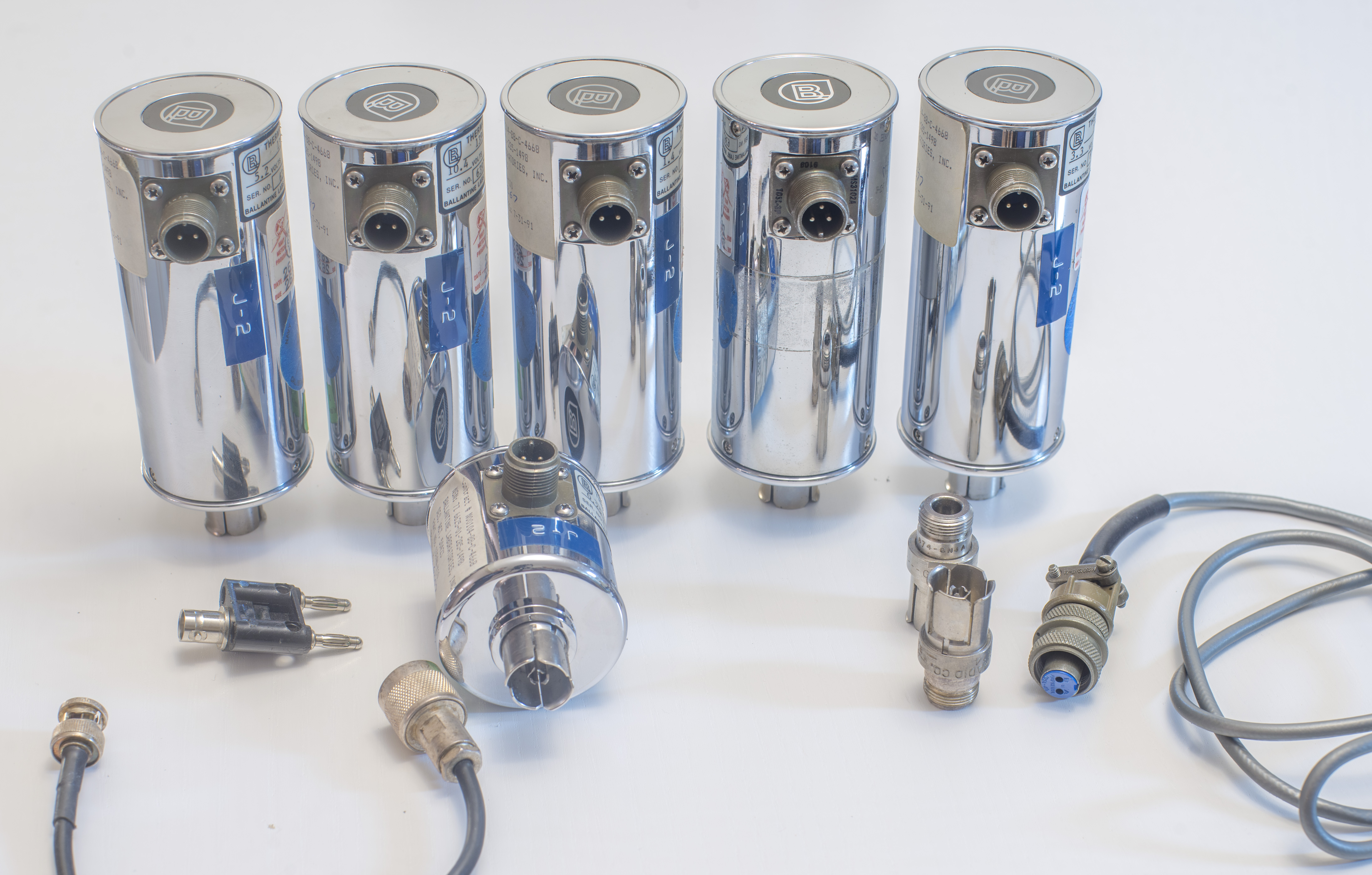
- Input connector type : GR874PB coaxial, output special 2-pin or 3-pin male MS3102A-10SL
- Output voltage full scale : 7 mVDC ±12%
- DC reversal : ±0.04 % or ±0.005 % for special option -10
- Nominal heater current : 5 mARMS
Ballantine 1394A datasheet page
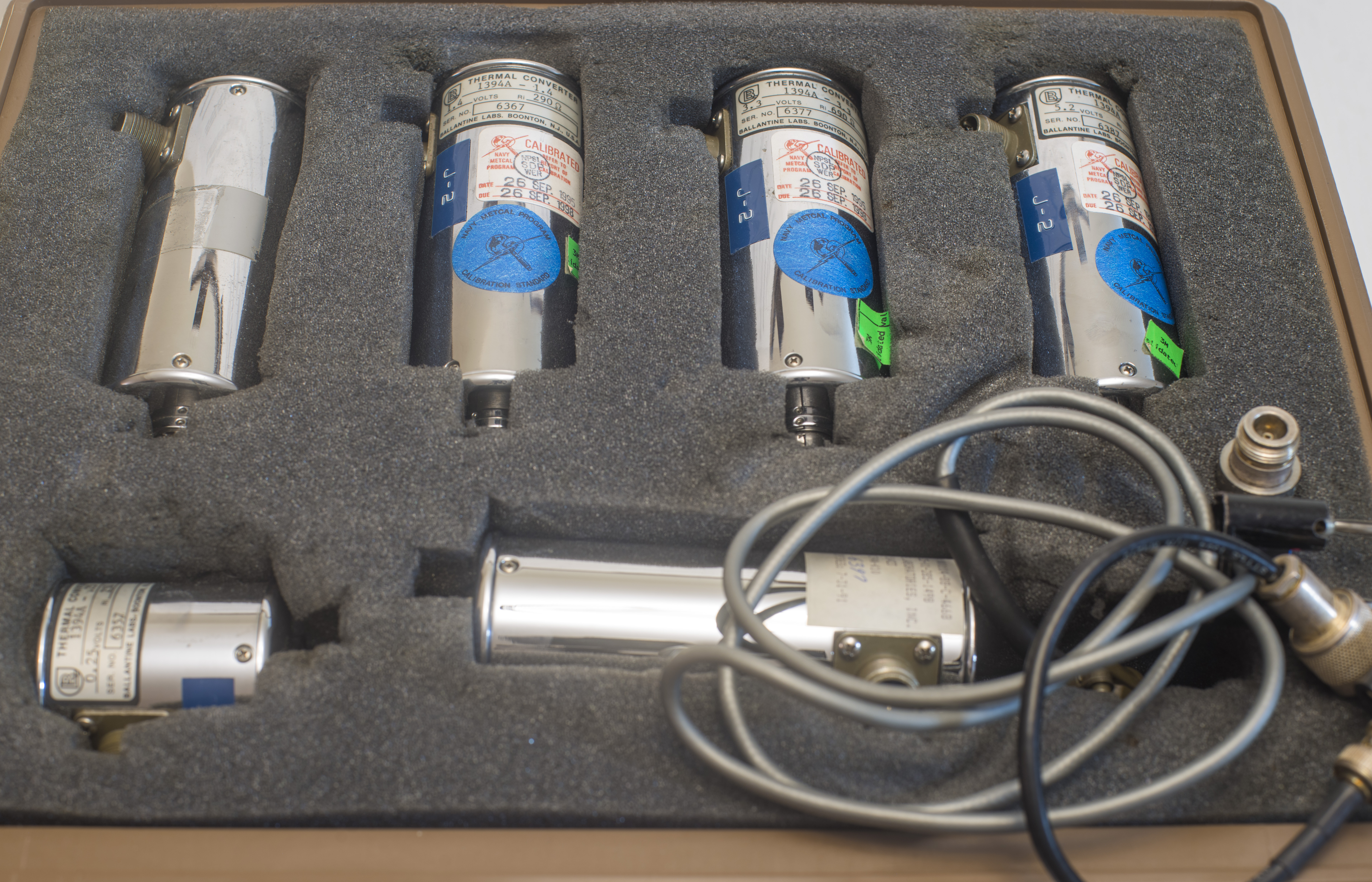
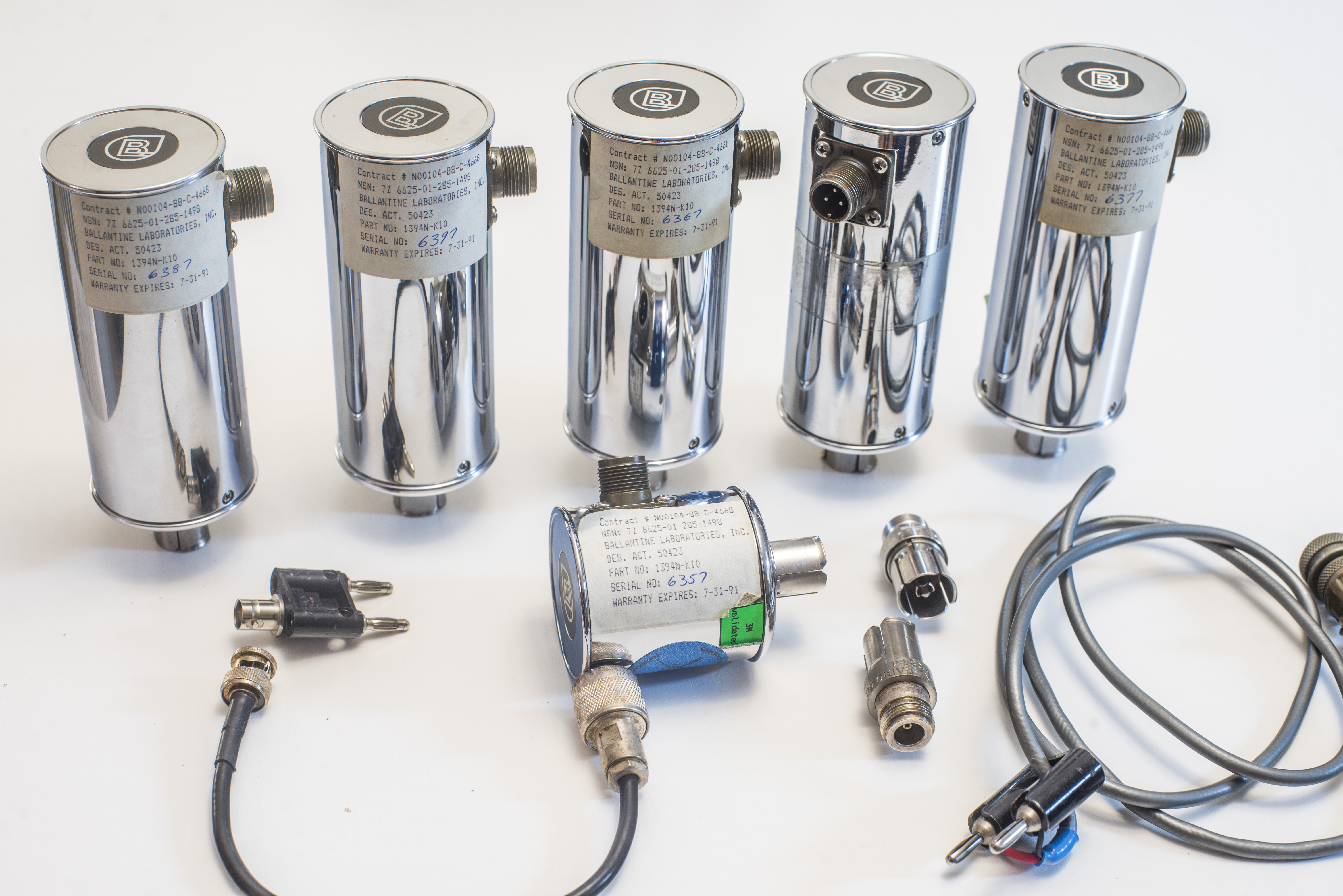
Kit supplied with 6 elements, two silver-plated Type N female to GenRad GR874 unisex adapters, short N to BNC cable and low-thermal MS3102A-10SL-2P cable.
Thermal convertors are easily damaged by even brief and moderate over-voltage! Do not leave TVC connected to instrument when not in test, and check automated procedures without TVC to make sure of correct voltage amplitudes and settings.
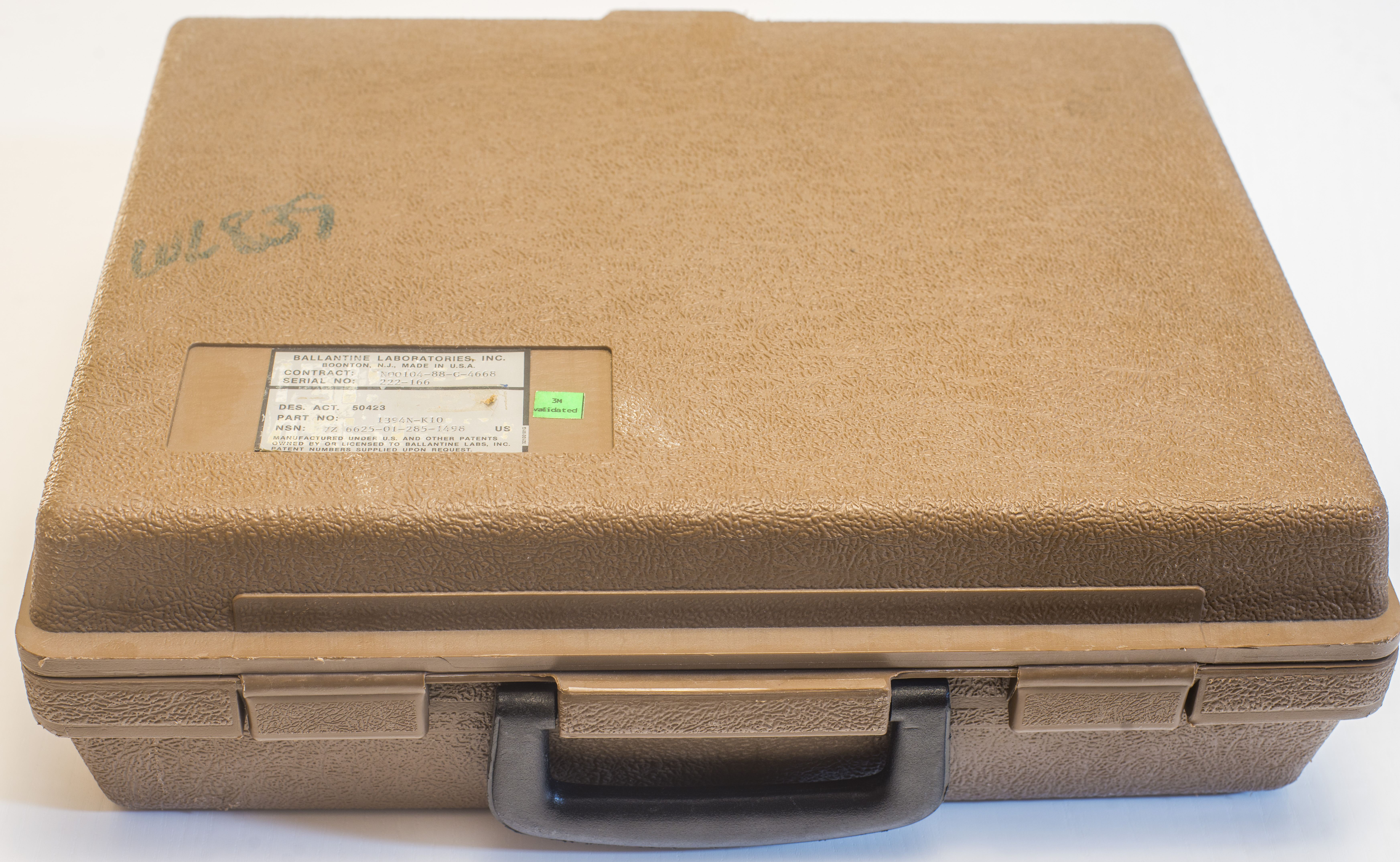
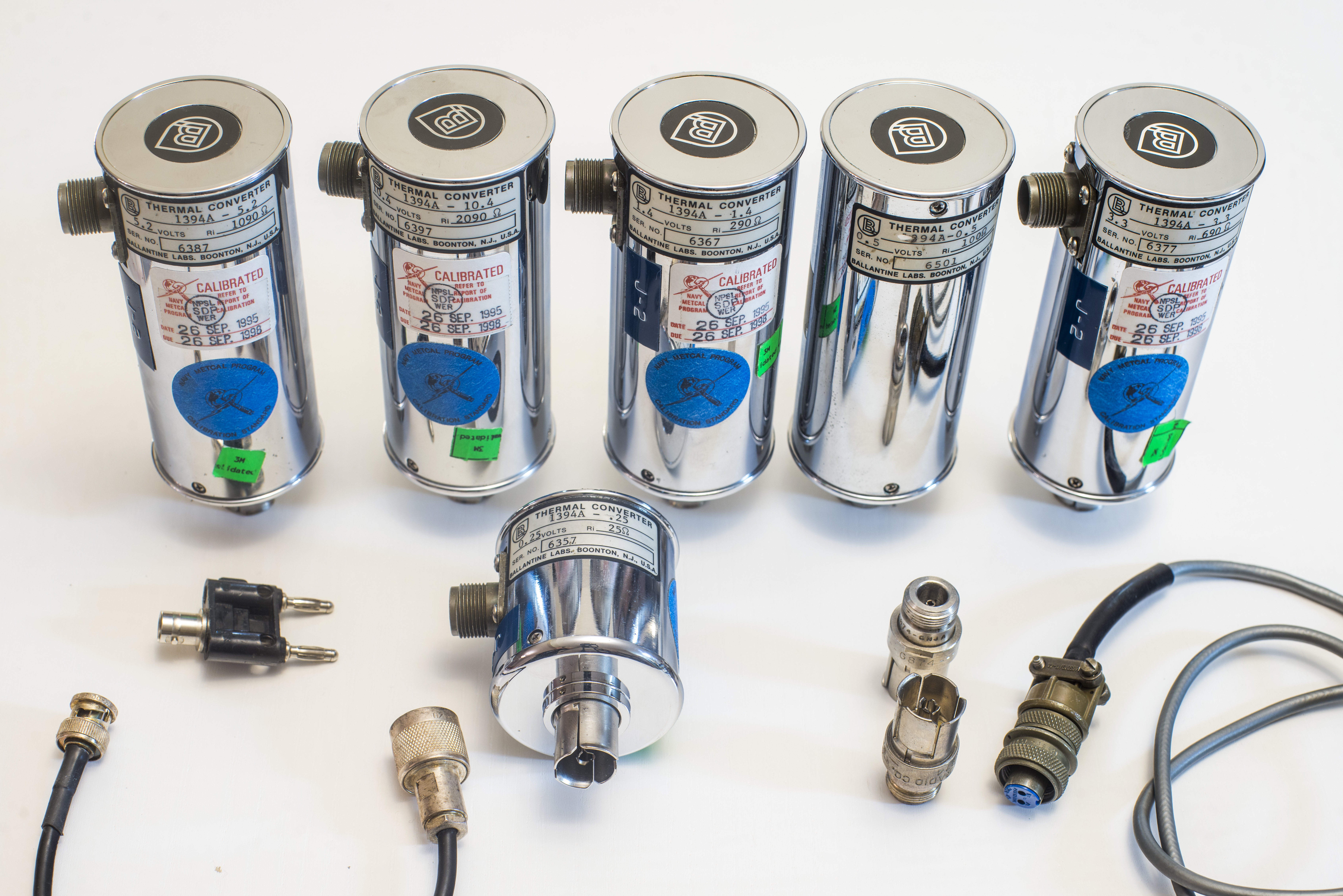
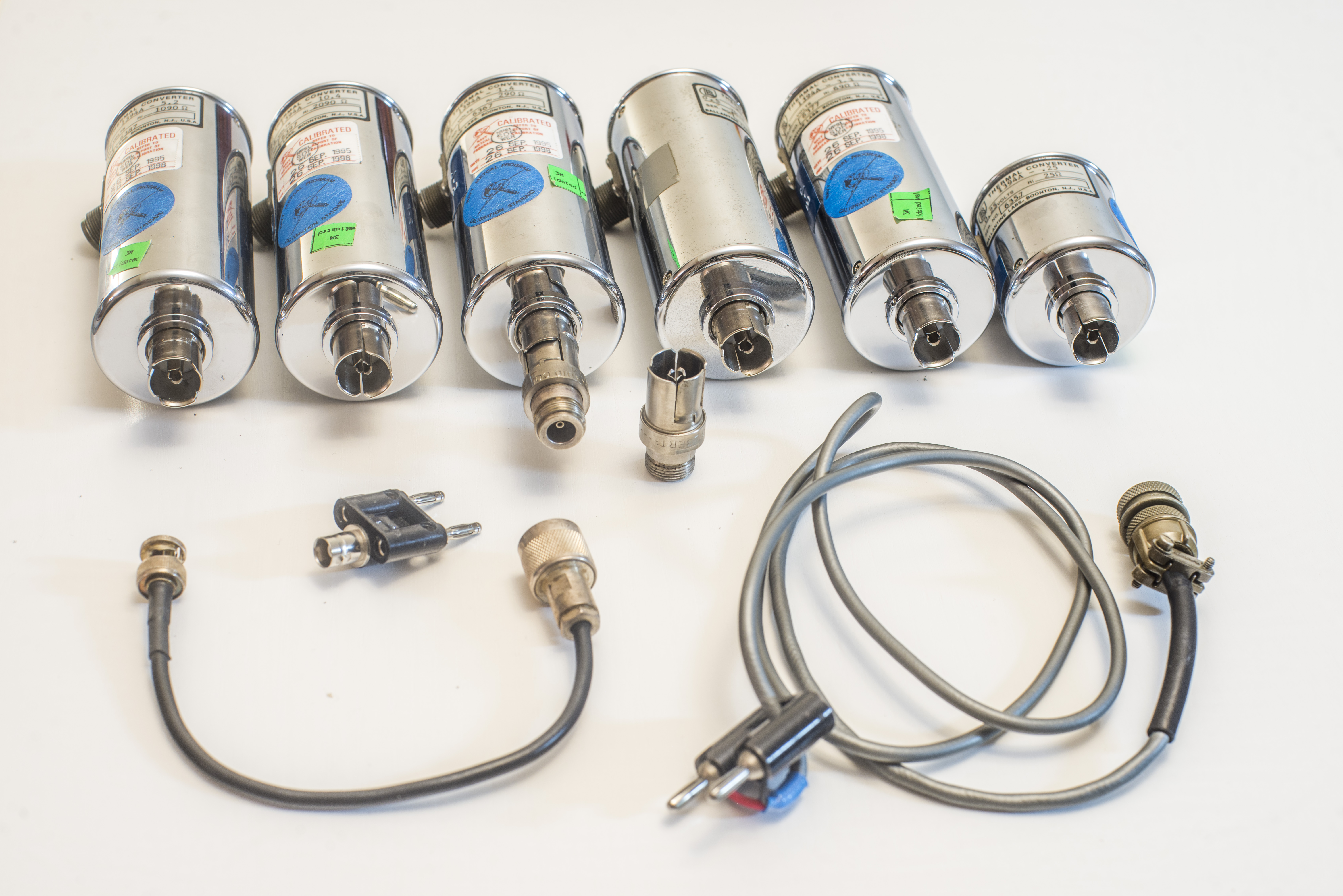
Set is shipped in plastic hard-case for additional protection of sensitive devices. Actual elements in our kit are:
| Element | Max input voltage | Input resistance | Calibration Uncertainty, % | Last calibration | |||||||
|---|---|---|---|---|---|---|---|---|---|---|---|
| Model | V | Ω | 20Hz-20 kHz | 50 kHz | 100 kHz | 1 MHz | 10 MHz | 20 MHz | 30 MHz | 50 MHz | +23°C by NPSL |
| 1394A-10.4 | 10.4 | 2090 Ω | 0.000 | 0.001 | 0.002 | 0.030 | 0.020 | 0.040 | 0.200 | 0.300 | 7V, 27 SEP 1995 |
| 1394A-5.2 | 5.2 | 1090 Ω | 0.000 | 0.001 | 0.002 | 0.020 | -0.050 | -0.080 | -0.100 | -1.200 | 5.2V, 27 SEP 1995 |
| 1394A-3.3 | 3.3 | 690 Ω | 0.000 | 0.000 | 0.012 | 0.030 | -0.040 | -0.090 | -0.200 | -0.600 | 3V, 27 SEP 1995 |
| 1394A-1.4 | 1.4 | 290 Ω | 0.001 | 0.002 | 0.004 | 0.050 | -0.060 | -0.100 | -0.100 | -0.500 | 1V, 27 SEP 1995 |
| 1394A-0.5 | 0.5 | 100 Ω | No report | No report | |||||||
| 1394A-0.25 | 0.25 | 25 Ω | No report | No report | |||||||
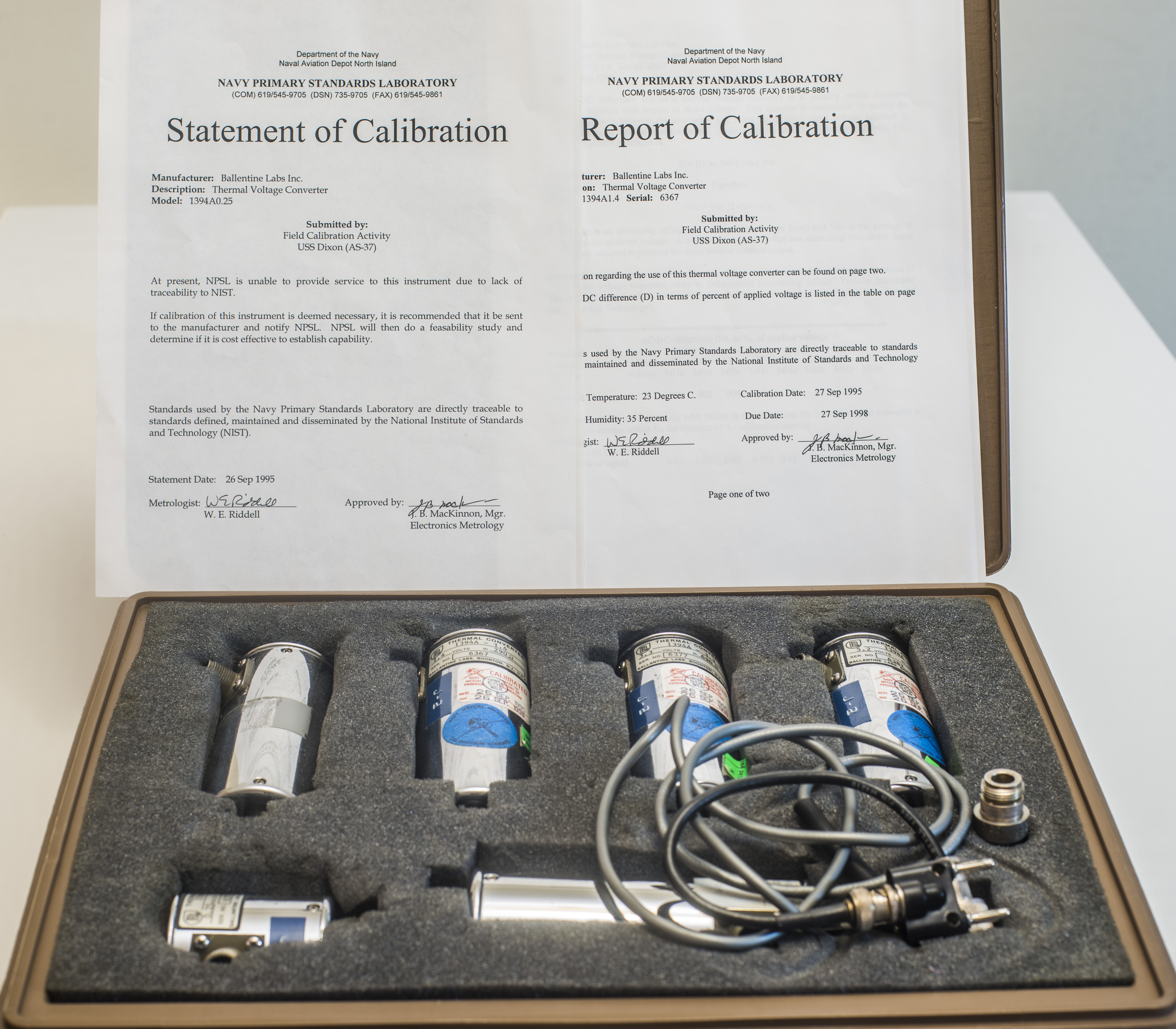
There is digitized copy of calibration documents supplied with our set:
Ballantine 1394N set calibration documents
Interesting that 0.25V element and 3-pin connectized element are not calibrated by Navy lab :).
Low voltage 0.5V and 0.25V type elements did not have calibration report, just a statement that Navy lab was not able to provide traceable calibration service.
Since even calibrated TVCs were tested good 25 years ago we would need to retest all elements anyway, so no big deal.
Another fun fact, 0.5V element has 3 pin connector and not the 2-pin like all the other ones. So I will have to build two different cables to use the elements. Not big deal, as I’m sure Ballantine 1605B calibration output have also 3-pin type output connector and I bought a connector for that cable.
Also GR874 to N adapters would need some cleaning to remove tarnish on the surfaces.
Larger elements are rather heavy with steel case, so they must be supported if used back to back w/o cables to test AC source or perform calibration of AC voltmeter function at DUT.
Performance benchmarks before traceable calibration
Test system consist of next equipment:
- High stability programmable source, Fluke 5720A calibrator, for both AC and DC volts
- DUT standard – in this case Ballantine 1394A TVC element
- Reference AC standard – Fluke 792A AC/DC transfer system
- Two digital nanovoltmeters (Keithley 2182A and Keysight 34420A) to monitor the output of AC TVC.
- Terasic DE1-SoC FPGA board running linux with LAN-GPIB bridge Keysight E5810A
The measuring sequence for signals adopted in these tests is AC, +DC, -DC, AC again. The readings from digitizers/nanovoltmeters are used to compute measurement results and characteristics and the AC-DC difference of the test devices. The complete comparison procedure, including all data and statistical analysis was automated and performed without any interruption from user.
AC-DC Difference
AC source stability and noise
DC source stability and noise
DC reversal and parasitic thermal EMF measurement
Response time for DC full-scale signal
Response time for AC full-scale signal (60 Hz)
Projects like this are born from passion and a desire to share how things work. Education is the foundation of a healthy society - especially important in today's volatile world. xDevs began as a personal project notepad in Kherson, Ukraine back in 2008 and has grown with support of passionate readers just like you. There are no (and never will be) any ads, sponsors or shareholders behind xDevs.com, just a commitment to inspire and help learning. If you are in a position to help others like us, please consider supporting xDevs.com’s home-country Ukraine in its defense of freedom to speak, freedom to live in peace and freedom to choose their way. You can use official site to support Ukraine – United24 or Help99. Every cent counts.
Modified: Aug. 19, 2020, 5:41 a.m.