DC loads are useful and important class of test equipment for testing and validation of power supply performance. Good quality power is a key for reliable operation of any electronics, and DC loads allow to test power supplies with any output condition and power loading, as well as perform dynamic transient tests and protection circuits operation. Chroma ATE, founded in 1984, is one of leading vendors in this market, providing industry standard solutions for high-power AC/DC loads and sources.
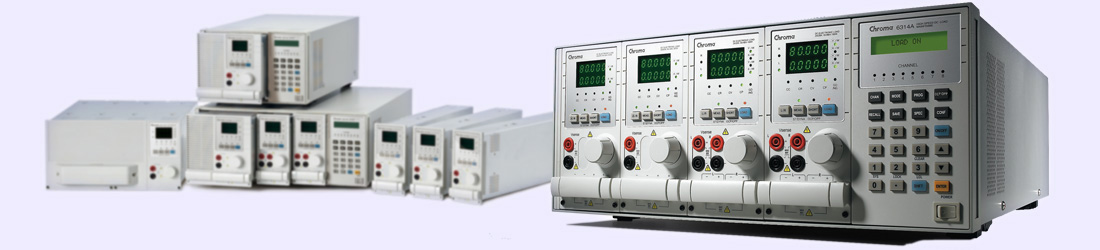
Courtesy: Chroma USA
Programmable DC Electronic Load 6310 Series Operation & Programming Manual
This module have next feature set:
- Constant current (CC), constant resistance (CR) and constant voltage (CV) operation modes.
- Programmable slew rate, load levels, load periods and conduct voltage (Von).
- Programmable dynamic loading with speed up to 20KHz.
- Minimum input resistance allows load to sink high current even with low input voltage (1 V).
- Selective voltage and current ranges.
- Remote sensing capability.
- 100 sets of memories to save/recall user-definable setups.
- 10 sets of programs to link files for automatic test.
- 15-bit A/D converter with precision measurement.
- Short circuit simulation.
- Automatic GO/NG inspection to confirm UUT within spec.
- Independent GO/NG signals for each channel
- The typical temperature coefficient is 100 ppm.
Particular module 63103A have single channel with maximum current 60A, power up to 300W and voltage from 1V to 80V. Resolution for current setting is 15mA in high-current mode, or 1.5mA in low current mode, with 0.1% accuracy. Current slew rate is programmable from 10mA to 2.5A/µs
Module size is 81 × 172 × 495mm (WxHxD) with 4.2kg of weight.
Internal construction
Primary voltage reference is Linear LT1236AIS8-10, according to Linear top marking decode table, located near TPA402 VREFA test point in top right corner on digital PCB. This is 5ppm/°C trimmed to 0.05% low noise precision reference chip.
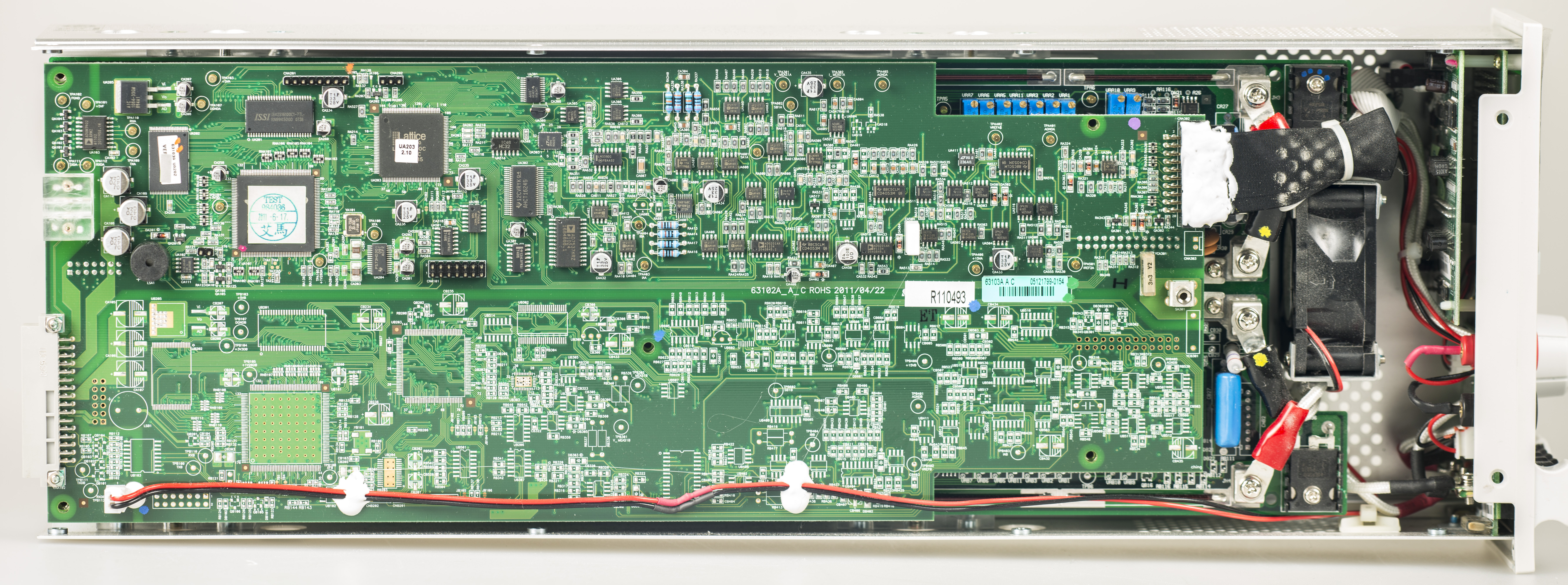
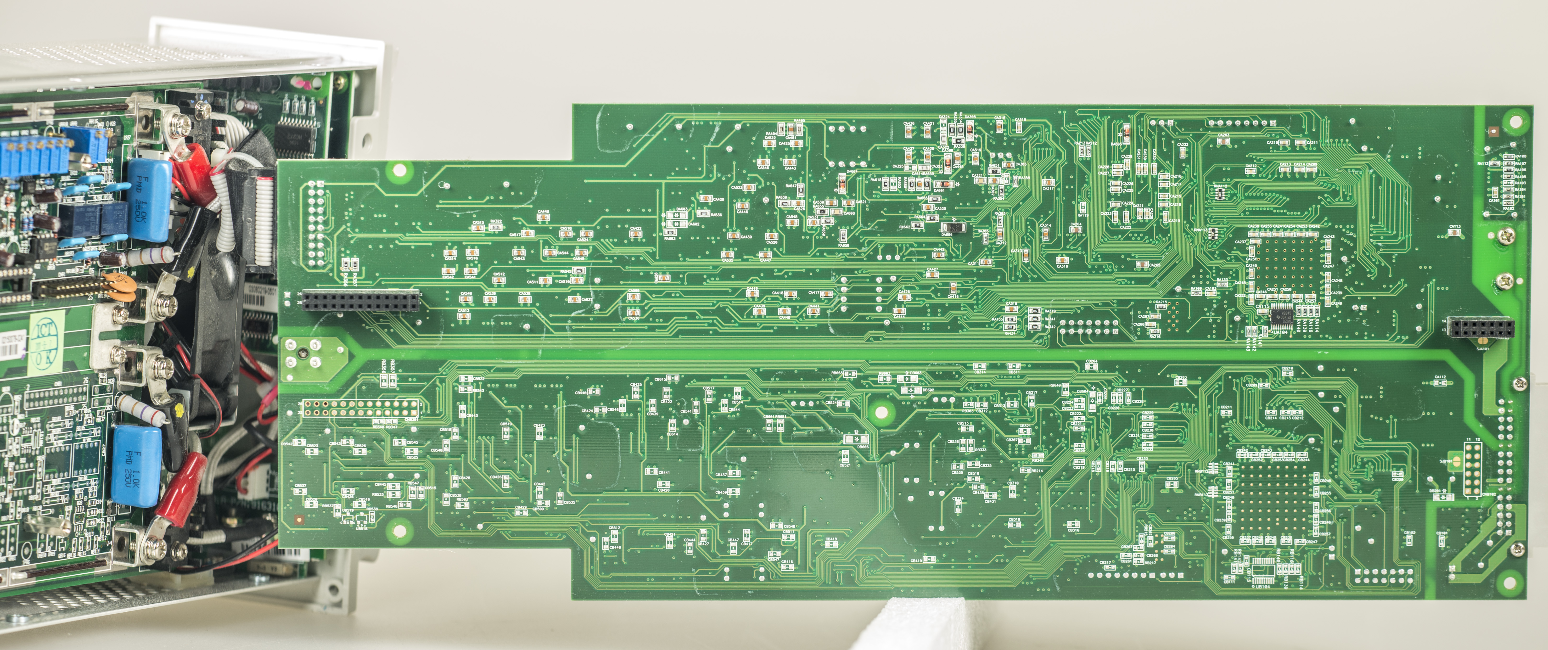
Module build like a sandwitch of boards, with digital control PCB on top. There are processor, some ISSI SRAM, NOR Flash chip and mainframe port on left side of board. Board is universal, supporting two channels, but since 63103A is single channel module, all bottom channel components are not populated. There is Lattice glue logic FPGA chip to do all bridging between processor and analog parts.
To control current and voltage Chroma used Analog devices AD7537KRZ, dual 12-bit DAC with current output, controlled via SPI interface. It’s relative accuracy is ½ LSB, gain error 3 LSB and output settling time 1.5uS. Output noise is quite low, 25 nV/sqrt Hz typical
Measurement part is processed by Linear LTC2444 24-bit sigma-delta 8-channel ADC. Per it’s datasheet linearity is 15 ppm/VREF max, and output rate is up to 8 kHz.
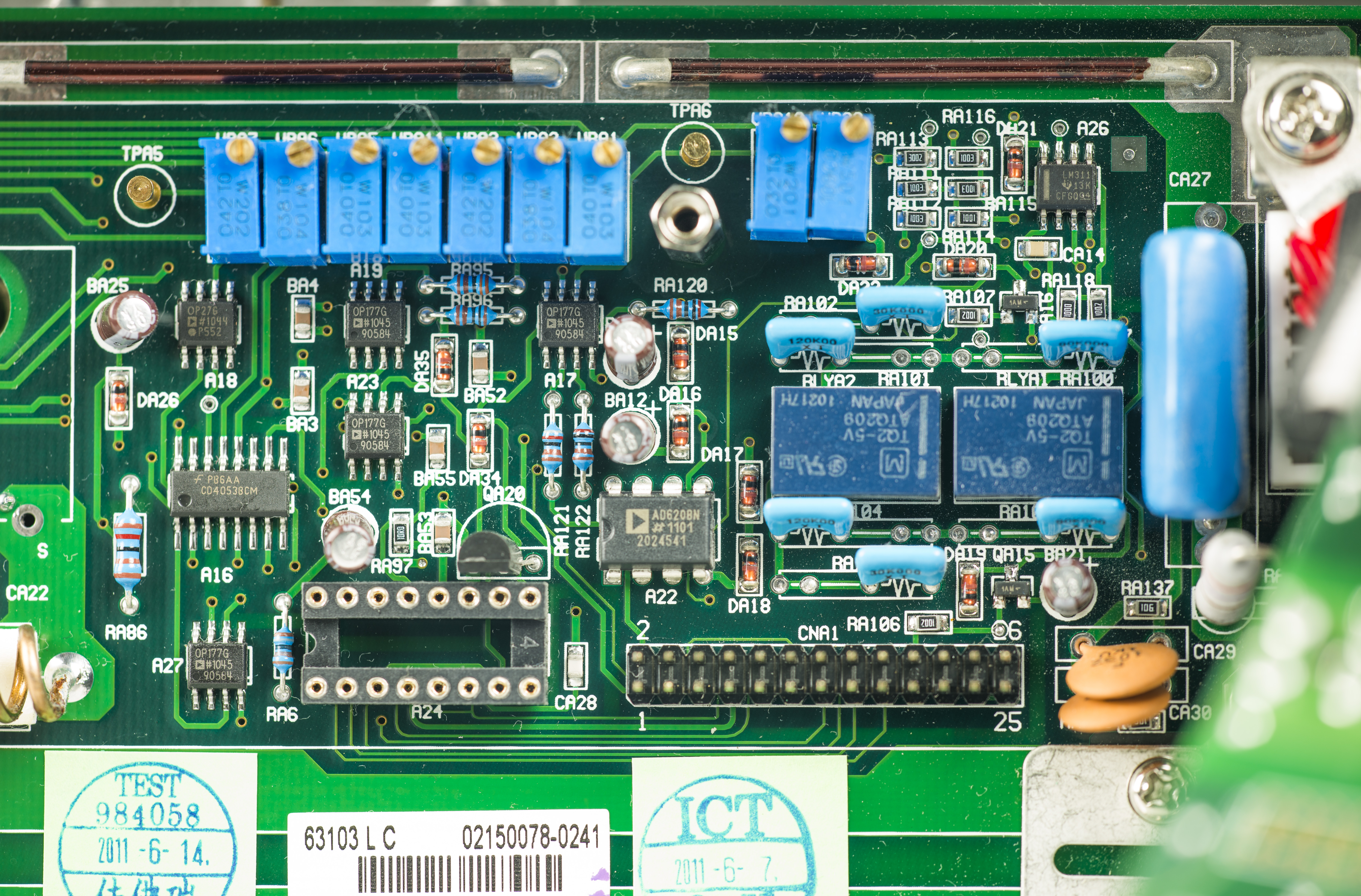
There is a great amount of Analog devices OP2177 opamps on boards, doing all signal processing before it reach power cells.
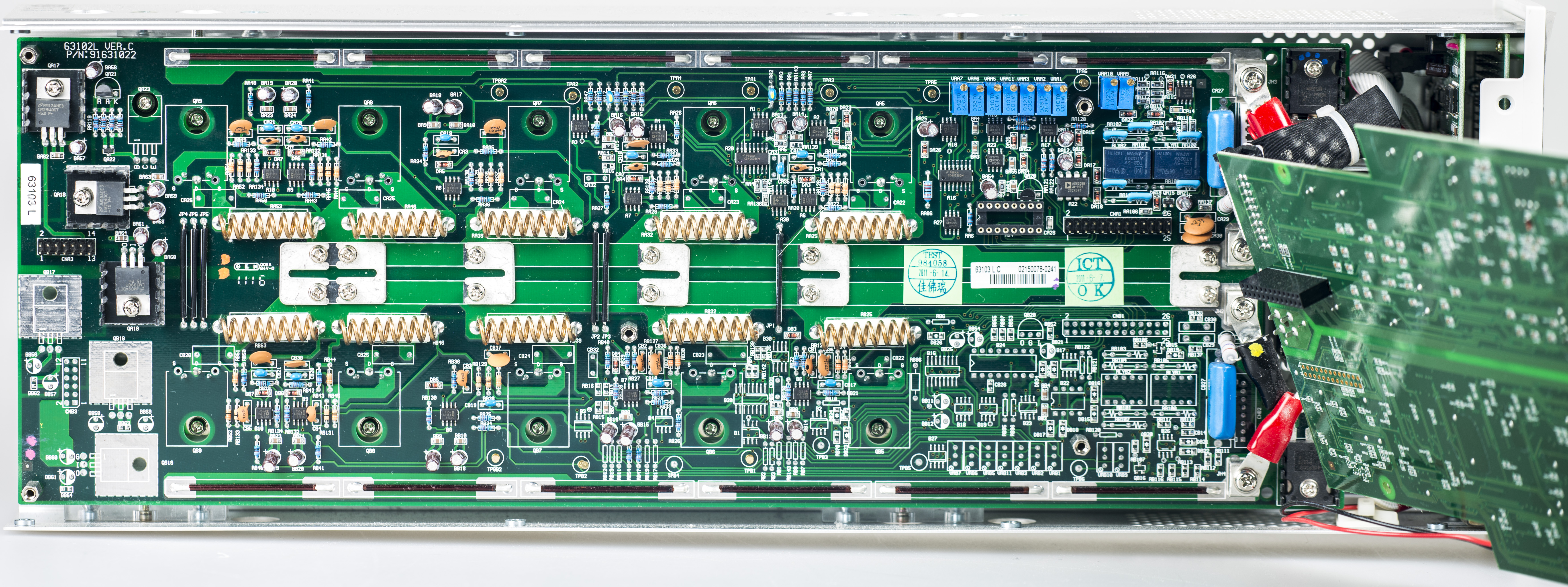
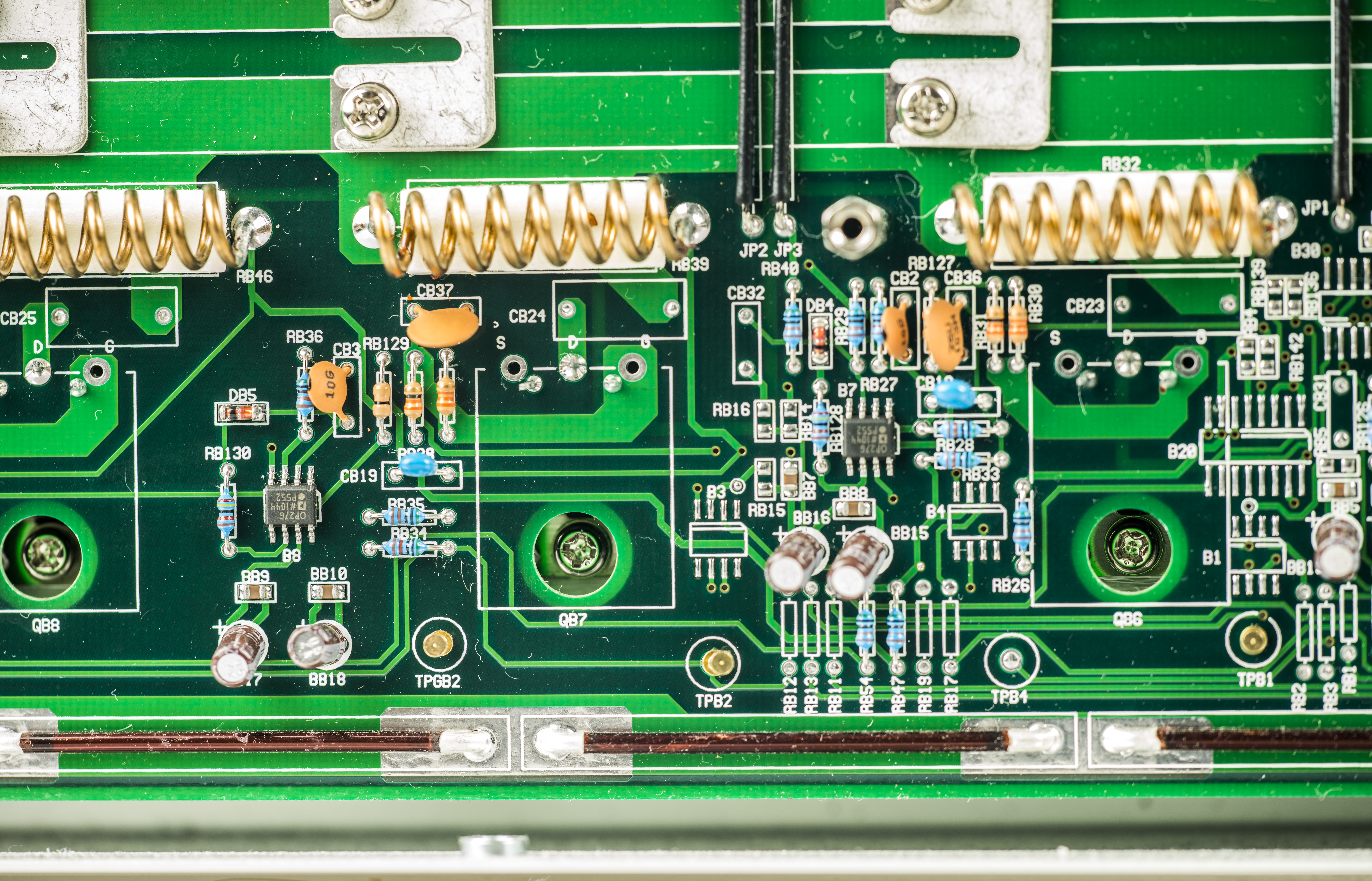
On high-power side, there are 10 identical current sinks, each using TO-247 package MOSFET, wirewound high-power shunts, controlled by Analog devices OP27 low-noise amplifiers.
Ten blue trimmers on top right side of analog power board are likely used to adjust each channel offsets for calibration and balancing. Fan on front side is directing airflow thru solid heatsink
under power board to dissipate heat and direct it outside of chassis.
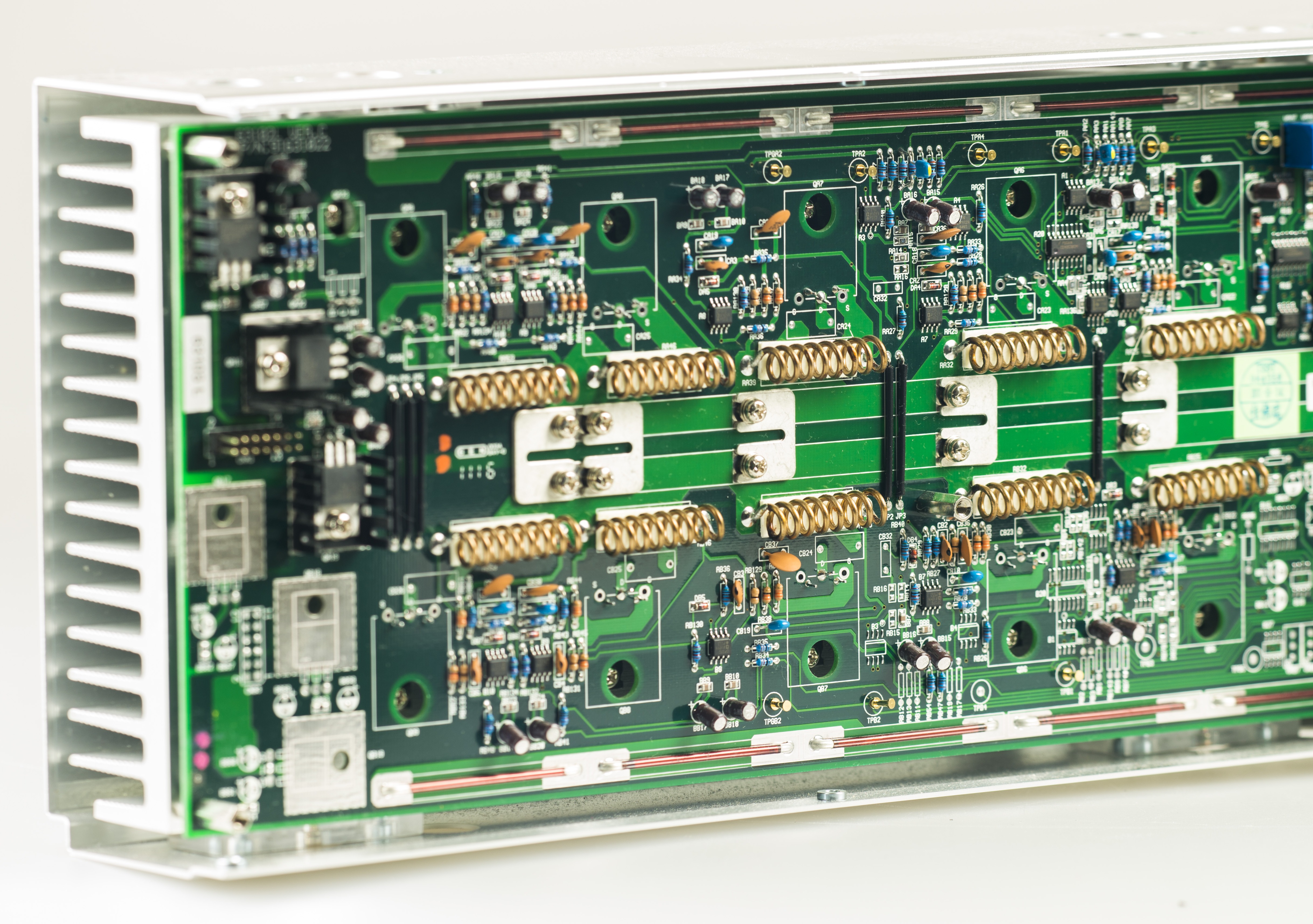
There are thick busbars to reduce resistance and inductance on high current path to and from power MOSFETs.

Since module is still functional and used, I’ll not go with full disassembly this time.
Back of top digital board:
Close-up for interface port between boards, trimmers and other analog parts.
One of power channel cells and MOSFET control circuitry.
Projects like this are born from passion and a desire to share how things work. Education is the foundation of a healthy society - especially important in today's volatile world. xDevs began as a personal project notepad in Kherson, Ukraine back in 2008 and has grown with support of passionate readers just like you. There are no (and never will be) any ads, sponsors or shareholders behind xDevs.com, just a commitment to inspire and help learning. If you are in a position to help others like us, please consider supporting xDevs.com’s home-country Ukraine in its defense of freedom to speak, freedom to live in peace and freedom to choose their way. You can use official site to support Ukraine – United24 or Help99. Every cent counts.
Modified: Aug. 2, 2015, 4:22 p.m.